

Page 1

- ...
:.,
.
. .
·~.·i~~·;..
·-
..
. '
_.,.--·
;
..
....
:.
··
..
•\
. .
.r
i
1
.
:.
~'
·-·-
...
·,_··
4.
...
15
_,.
,.•
.•
1979.
Page 2

- 1
OPTIPHOT, LABOPHOT
BOOY
8,
F,
ER,
UW-TUBE
STAGE
WITH
VERTICAL
f
HANDLE
' (
Page 3

CONTENTS
CARE
TOOLS
MECHANISM
DISASSEMBL
REASSEMBL
FOR
ANO
1.
2.
3.
4.
5.
1.
1.
2.
3.
4.
1.
2.
3.
4.
Tools
Special
Lubricants
Adhesive
Others
Coaxial
Coaxial
Substage
Arm
Base
Coaxial
Substage
Arm
Base
STARTING REPAIR
PREPARATIONS
for
General
Tools
....................................................
.......................................................
. . . . . . . . . . . . . . . . . . . . . . . . . . . . . . . . . . . . . . . . . . . . . . . . . . . . . . . . . 6
to
be
Repaired . . . . . . . . . . . . . . . . . . . . . . . . . . . . . . . . . . . . . . . . . . . . . . .
ANO
PRINCIPLE
Coarse
Y PROCEDURE . . . . . . . . . . . . . . . . . . . . . . . . . . . . . . . . . . . . . . . . . . . . . . . .
Coarse
Unit
Unit
Y PROCEDURE . . . . . . . . . . . . . . . . . . . . . . . . . . . . . . . . . . . . . . . . . . . . . . . . .
Coarse
Unit
Unit
and
and
Unit
. . . . . . . . . . . . . . . . . . . . . . . . . . . . . . . . . . . . . . . . . . . . . . . . . . . . .
. . . . . . . . . . . . . . . . . . . . . . . . . . . . . . . . . . . . . . . . . . . . . . . . . . . . . . . .
. . . . . . . . . . . . . . . . . . . . . . . . . . . . . . . . . . . . . . . . . . . . . . . . . . . . . . . .
and
Unit
. . . . . . . . . . . . . . . . . . . . . . . . . . . . . . . . . . . . . . . . . . . . . . . . . . . . .
........................................................
. . . . . . . . . . . . . . . . . . . . . . . . . . . . . . . . . . . . . . . . . . . . . . . . . . . . . . . .
.............................................
Use
..............................................
...............................................
Fine Focus
Fine Focus
Fine Focus
Unit
. . . . . . . . . . . . . . . . . . . . . . . . . . . . . . . . . . . . . l 9
Unit
. . . . . . . . . . . . . . . . . . . . . . . . . . . . . . . . . . . . .
Unit
. . . . . . . . . . . . . . . . . . . . . . . . . . . . . . . . . . . . .
.
.
.
.
6
18
19
21
21
23
26
29
32
32
34
36
37
ADJUSTMENT
1.
2.
3.
4.
5.
6.
7. Tube Length . . . . . . . . . . . . . . . . . . . . . . . . . . . . . . . . . . . . . . . . . . . . . . . . . . . . . .
8.
...........................................................
Torque of
Smooth Tuming
Smooth Tuming
Parallelism between the Tube Attaching
Centering the Tube Attaching
Centering
Adjustment
Coarse
of
Focus
Knob
. . . . . . . . . . . . . . . . . . . . . . . . . . . . . . . . . . . . . . . . .
of
the Left
of
the Right Fine Focus
Optical System
of
Brightness Contrai Circuit . . . . . . . . . . . . . . . . . . . . . . . . . . . . . . . . .
Fine
Focus
and
Stage
in
the Microscope
Knob
Knob
and
Stage
Attaching
. . . . . . . . . . . . . . . . . . . . . . . . . . . . .
............................
Attaching Surfaces . . . . . . . . . . . . .
Part
. . . . . . . . . . . . . . . . . . . . . . .
Base
. . . . . . . . . . . . . . . . . . . . . . . . . 4 l
38
38
38
39
39
40
4 l
42
Page 4
R-4104.A
CARE
FOR
STARTING REPAIR
CARE
•
e For replacement and others
e
• Take every caution
•
e
• Before replacing the
• For cleaning the
FOR
STARTING REPAI R
When
carrying the microscope, hold
with
the
directly
Wltlle
the
thinner, etc.
Be
careful not to
Make
sure
referring
using
to
a gauze.
lamp
fingers.
is
lighted, never bring
near
to
in
leave
of the power source
the
indication found
lens
the
fuse
surfaces, füst
its
arm
of
the lamp bulb,
any
inflammable substances
lamp housing.
handling against shock.
dust,
t1nger
marks, etc.
voltage
in
the transformer,
to
be
on
the transformer.
remove
dust,
with
one
hand.
do
not touch
on
the
used
(for example: UNE
pull
out
the
using
a sott
tenses,
plug
:rnd
1ts
base
with the other.
it.
aiter putting out the lamp,
such
as
alcohol, gasoline,
lamp
bulb, etc.
IOOV,
LAMP
of
the
power source cord.
haJr
brush, or
wipe
6V,
it
off lightly,
20W),
• Only
e For cleaning the parts painted or
e
• Apply only specified
for
removing
gauze, soaked with a bit of absolute alcohol (ethanol
alcohol, ether, thinner, etc.
Do
not
use
of
the instrument.
finger
marks or grease,
made
other tools other than the specified, except
oils
to
the parts, r"ferring
of
use
plastic,
a soft,
avoid
to
the
clean
cotton cloth, specified
or
methanol).
the
use
of such organic solvents
for
an
unavoidable
lubricant table, to keep
case.
up
lens
the
tissue
or
as
efficiency
-1-
Page 5

R-4104.A
TOOLS ANO PREPARATIONS
TOOLS ANO PREPARATIONS
1.
Toais
for
General Use
Name
- screwdriver
6
4 + screwdriver
set
set
Pair of tweezers (stainless)
Blower
Injector (2cc)
or
Plastic
wooden hammer
Handlap
Hexagonal wrench
Flat type thread dnver
For
screwing.
For
screwing.
For cleaning lenses, etc.
For injecting oil.
1
For
applying impact.
Cointainer
For
set
screws
For
HS
bolts
1. T ools for General Use 2. Special T ools
Use
for
alcohol
(3mm, 4mm).
(3mm,
4mm,
Smm,
6mm)
2. Special
i Substage condenser
i positioning tool
1 Tube receptacle/substage
1 centering tool
(
Toais
Name
Parallelism measuring
base
Centered condenser 125144 (Fig. 4)
4X
Objective "
Eyepiece
CFW
IOX
Rightangle/Centering tool
Base
axis collimator
"
Number
125141
125142 (Fig.
1
(Fig.!)
2)
125143 (Fig. 3)
125145 (Fig. 5)
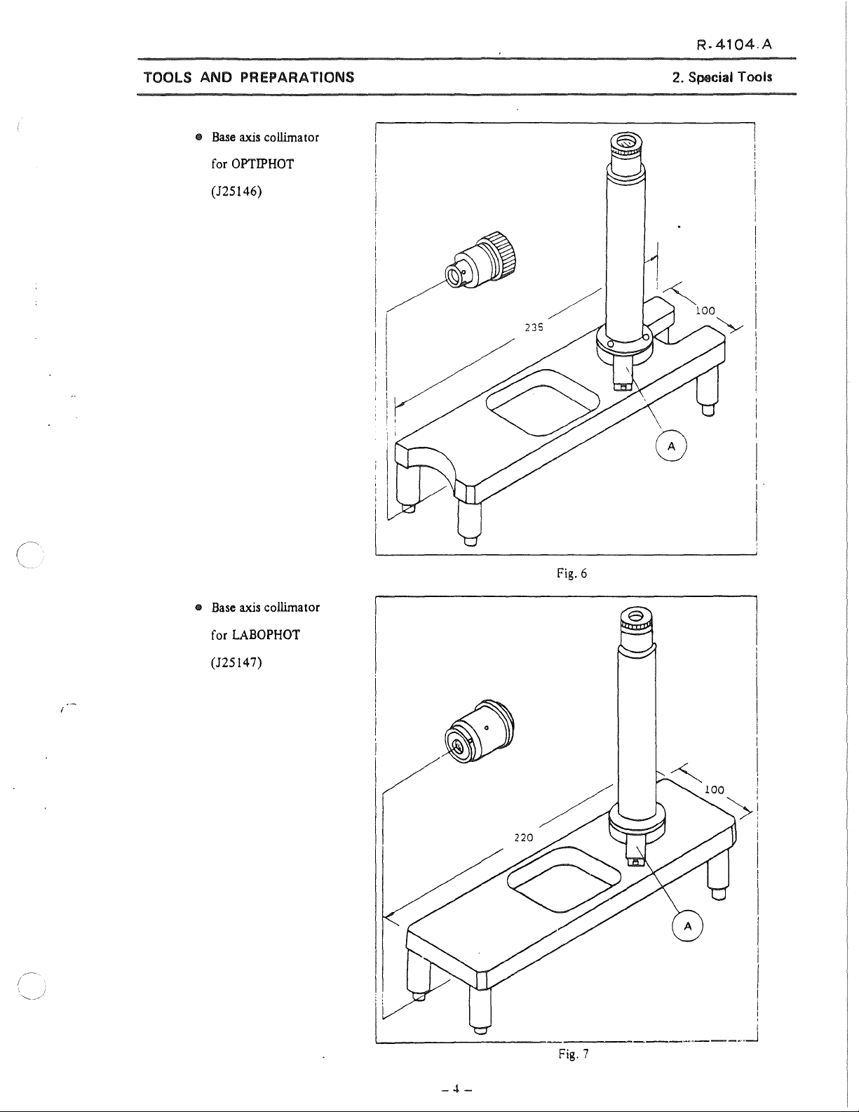
125146 (Fig. 6)
125147 (Fig. 7) For
For
For
For
For positional adjustment of
For adjusting
nosepiece
For OPTIPHOT
Use
positioning substage
and
centering tube receptacle
rightangle
of
nosepiece
"
" "
rightang!e of substage to
LABOPHOT
condenser
and
substage
to
substage
base
and
ann
1
1
1
1
1
i
1
i
1
1
i
1
1
'
!
'
Standard vertical eyepiece
tube ( with Kellner eyepiece)
Diopter adjusting telescope
Checker pattem reticle
Tension
ga1Jge 1 Kg,
500g For measuring torque
Centered objectives
IOX,
40X
Tubelength adjusting tool
Collimator
plane
parallel
19008
128004
IOX
128018
40XJ28019
125148 (Fig. 8) For measunng tubelength
For
measuring tubelength and parfocality
For adjusting optical
axis
of
eyepiece tube
For checking travei accuracy of
and
parfocality
stage
1
1
1
1
1
1
Page 6

R-4104.A
TOOLS
ANO PREPARATIONS
• Substage/condenser positioning
too! (125141)
e Tube receptacle/substage
centering too! (125142)
55 -
Fig.
1.
?:
.___,/
33
~
A.
~'
~~
~
2. Special Tools
8;
--_./
1
o
-e.
"'
Fig.
2
e Parailelism measuring base
(125143)
-
: 1
10
Fig.
• Now-eccentric condenser
r
(125144)
-
ss
-P89
e
3
~
---!
1
1
@}])
Fig.
4
•
Substage
tool (125145)
rightangle/centering
-72
i 1
1
___;
-3-
Ftg.
5
Page 7
R-4104.A
TOOLS ANO PREPARATIONS
e
Base
ax.is
collimator
for
OPTIPHOT
(125146)
i
;
l 1
I '
1 1
' 1
1
'
'1
1
! '
2. Special Tools
e
Base
for
(125147)
ax.is
collimator
LABOPHOT
Fig.
1
6
-4-
Fig.
_,,
____
.,_J
1
7
Page 8

R.4104.A
TOOLS ANO PREPARATIONS
€1
Tubelength adjusting too!
(125148)
Eyepiece
2. Special Toais
20X
Fig. 8
o
l
o
"'
-5-
Page 9

R.
4104.A
TOOLS ANO PREPARATIONS
3. Lubricant and Adhesive
(Coaxial coarse-fine focus unit)
OPTIPHOT
Lubricant (G7920)
/
Â
~@
Lubricant (G7920
Adhesive
(#616
X.
XP
1251~
'-'
124•
3. Lubricant and Adhesive
Adhesive
(1616)
Lubricant (G
Adhesive
(#2002)
79
20)
(
I
/
,foi
'----'
Adhesive
\
/
,
(#2002)
Lubricant
(G7920)
,/'/
/
,r--'/
' '
1191__,t ' /
--.
..
JI
;'
21\;:--<'
/
j
~106)..-/
""~~
Adhesive
iAdhegve
1101
(rtJ50)
/
/
(#410
~'
12s1A
'--..__.;
127) ,
~
B/M)
.§
Lubricant
(G
201)
Fig. 9
-6-
8
Page 10
R-4104.A
TOOLS ANO PREPARATIONS
Lubricant (G7920)
I'
1
!
/
(~11
128
\
Lubricant (G7920)
Adhesive
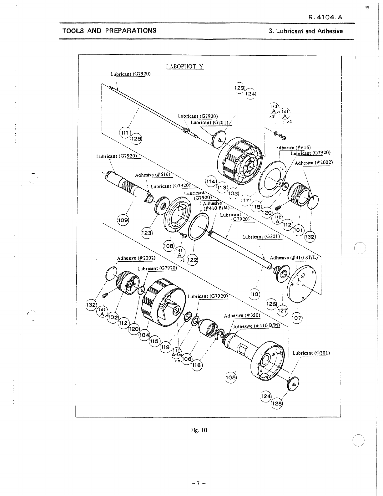
LABOPHOT
(#616)
Y
129l~
'---' 1241
3.
Lubricant
and
Adhesive
Adhesive
(#2002)
Lubricant (G7920)
I
Lubricant (G201)
Fig. 10
-7-
Page 11
TOOLS ANO PREPARATIONS
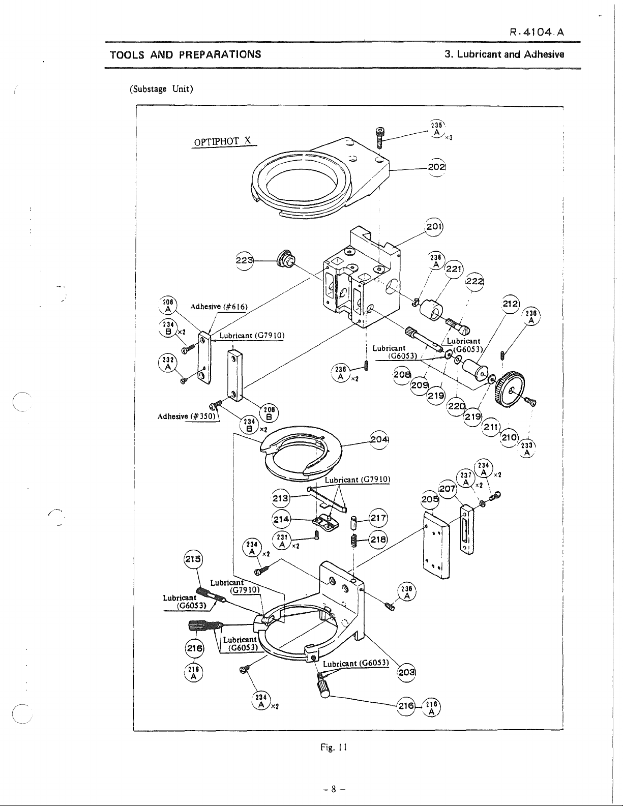
(Substage Unit)
R-4104.A
3.
Lubricant and Adhesive
e
208
A
OPTIPHOT
X
1----202)
,......__,
'--..__,-'
201
'@\
;M~221
Í @
/ I
'',--/'
Q
7
' , Lubricant (G60S 3)
ce,
---&~
Fig.
l l
-8-
')I
Page 12
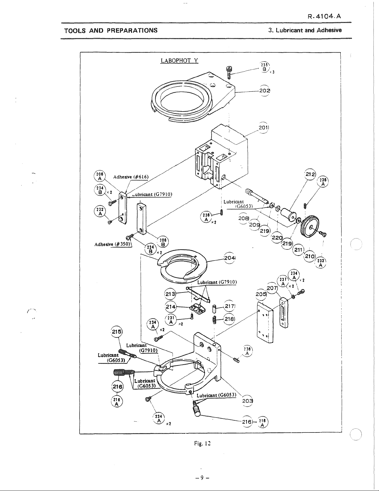
R-4104.A
TOOLS ANO PREPAAATIONS
LABOPHOT
Y
~
r
ç;
/ 2021
1:
;
Lubricant'
1
~
\ A 1 208)
'-!Yx2
________.
'
IG6053)
-~
'-----'
235\
~
___
201)
----!
'2o~
~219)
'-//~
3. Lubricant
-ª.,;"3
/
/
.
1
-~
and
Adhesive
~
'212)
/C~
1;
/
1
(~
(1i4l
~
~x2
\
,{m
-~x2
~Q):
ç~):
,
__
),,@\
-~
(~
!231\~<2
.---- 2Q
205)
'---../
~\-Ã'
1
\~X2
\
1
\
_j
-
~m
~;,;f-íli\
.__,/
:_A)
Fig.
-9-
12
Page 13
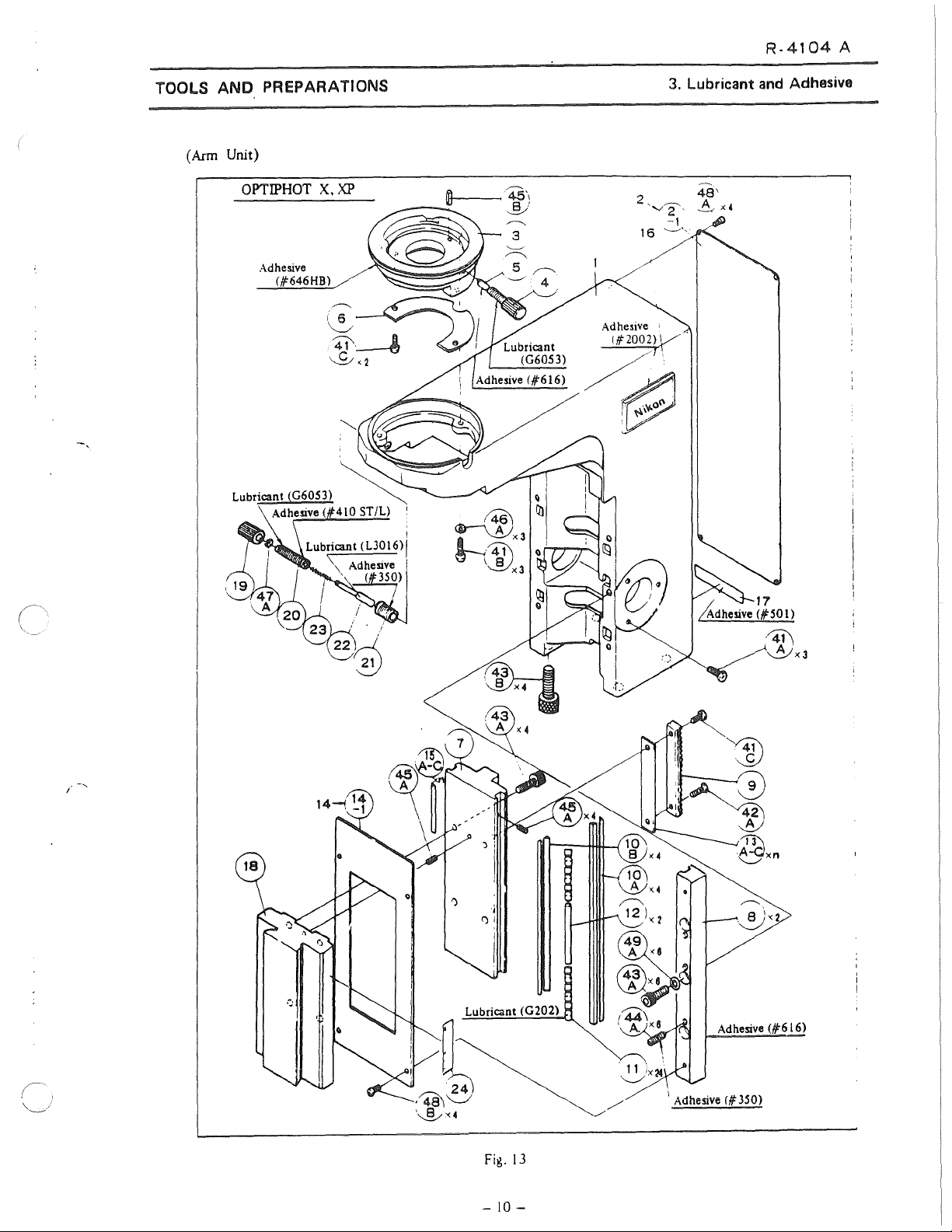
R-4104
A
TOOLS
(Arm Unit)
ANO
PREPARATIONS
OPTIPHOT
X.
XP
1----45\
----
~)
3. Lubricant and Adhesive
48'
A
X4
'~
!X4
:43
ti
A
.
11
'-.___/
ix24
1
Adhesive
Adhesive
f#'
350)
(#616)
Fig.
-
13
10-
Page 14
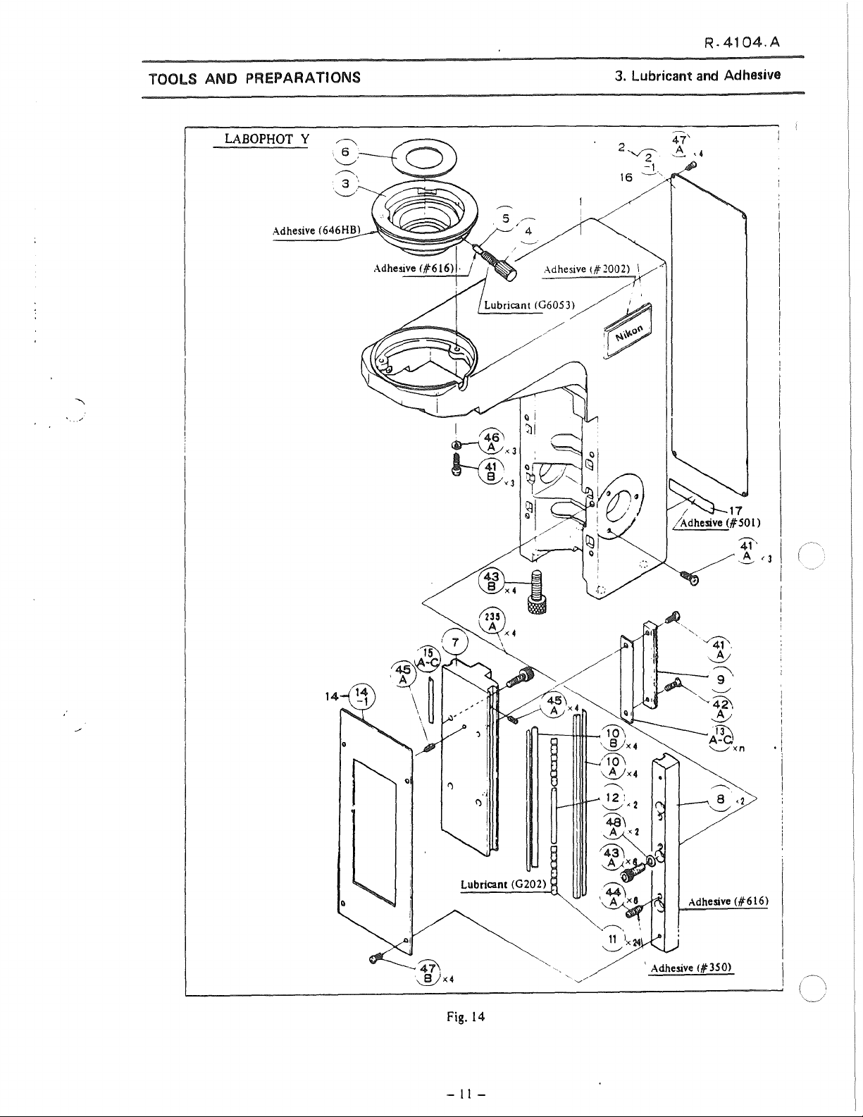
R-4104.A
TOOLS ANO PREPAAATIONS
LABOPHOT
Y
Adhesive (646HB)
3. Lubricant and Adhesive
Lubricant (G202)
Fig.
14
-
11
-
Adhesive
' Adhesive <1350)
(#616)
Page 15

R-4104.A
TOOLS ANO PREPARATIONS
(Nosepiece)
OPTIPHOT
Adhesive
Adhesive
X
(#'350)
(#'616)
~,,.........___~<2
Lubricant
'fl
Adhesive1304l
.
(#'350)
'Jf:
-~
~~)
~
(G202)
~~)
1 .
!
Adhes1ve (# 350)
3. Lubricant and Adhesive
,..--.._
312:
__,,
Adhesive í,\'"2002)
'-__,/
(~
\__)
Fig.
15
r-----3011
~
'-J
-
12
-
Page 16
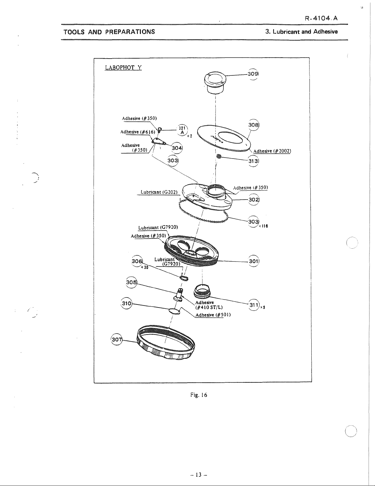
R-4104.A
TOOLS ANO PREPARATIONS
LABOPHOT
Y
Adhesive (# 350)
Adhesive
Adhesive
(#616)\lopL-__,
(#350)
Lubricant (G202)
~
r
.J21\
A J
~"2
0--309\
''ô
1
1
......,.=~~
:._____Q)
.(
1
~
~
~
308
Adhesive (#"2002)
~
Adheslve <#350)
~
302)
~·
3. Lubricant and Adhesive
Ooo
/ '
~~·303)
1
~
'_____./X
li
8
/
11------
j
Adhesive
Fig. 16
(#501)
~
301)
'----"''
-
13
-
Page 17
R-4104.A
TOOLS
ANO
PREPARATIONS
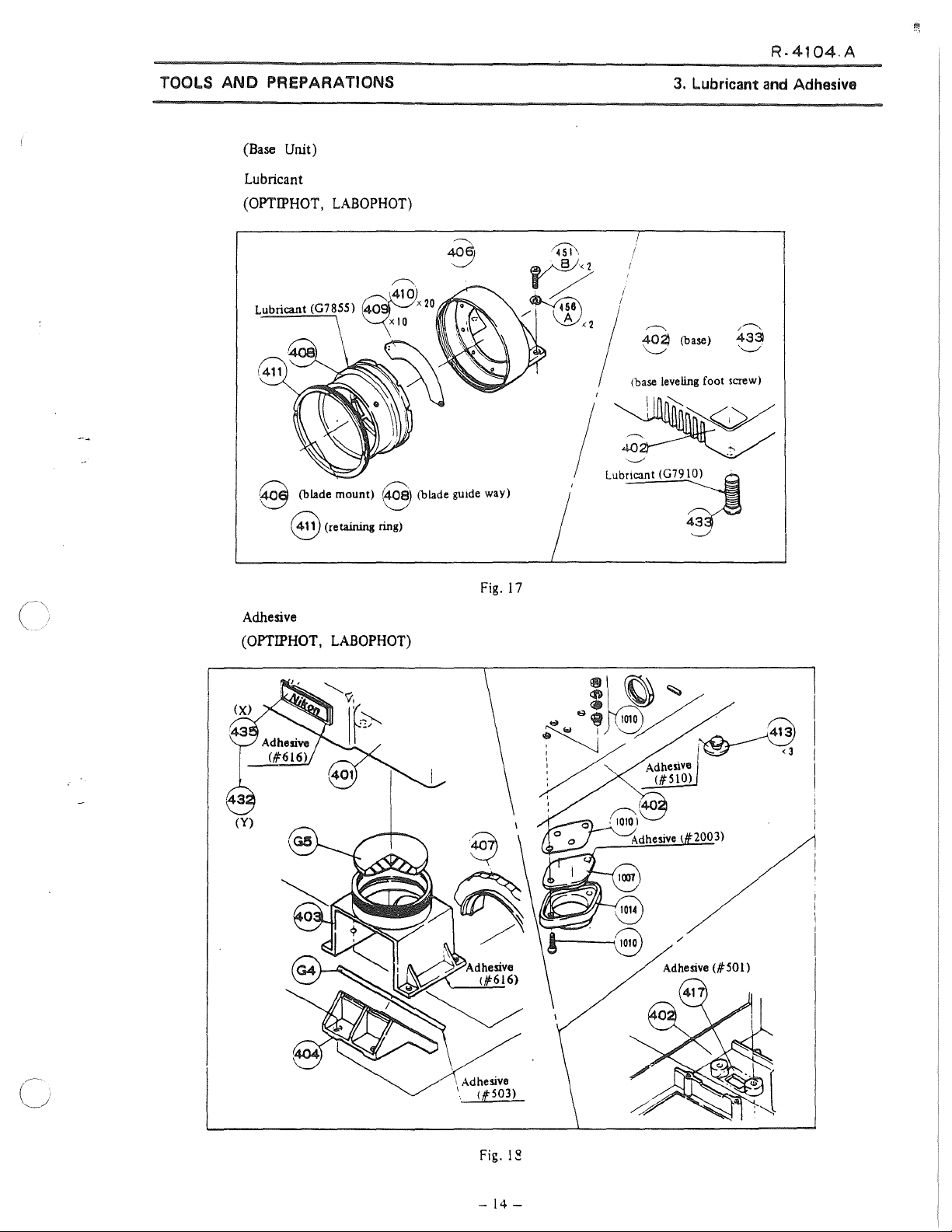
(Base Unit)
Lubricant
(OPTIPHOT,
S (biade
8 (retai.ning ring)
LABOPHOT)
mount)
8 (biade gu1de way)
/
"--"'
Lub~
3.
Lubricant
r---..
~
(base)
1base
leveling foot screw)
~
~
and
Adhesive
Adhesive
(OPTIPHOT,
LABOPHOT)
Fig.
17
2003)
/
1 Adhe:iive
1
(f503)
Fig. 1
-
14-
~
Page 18
R-4104
A
TOOLS ANO PREPARATIONS
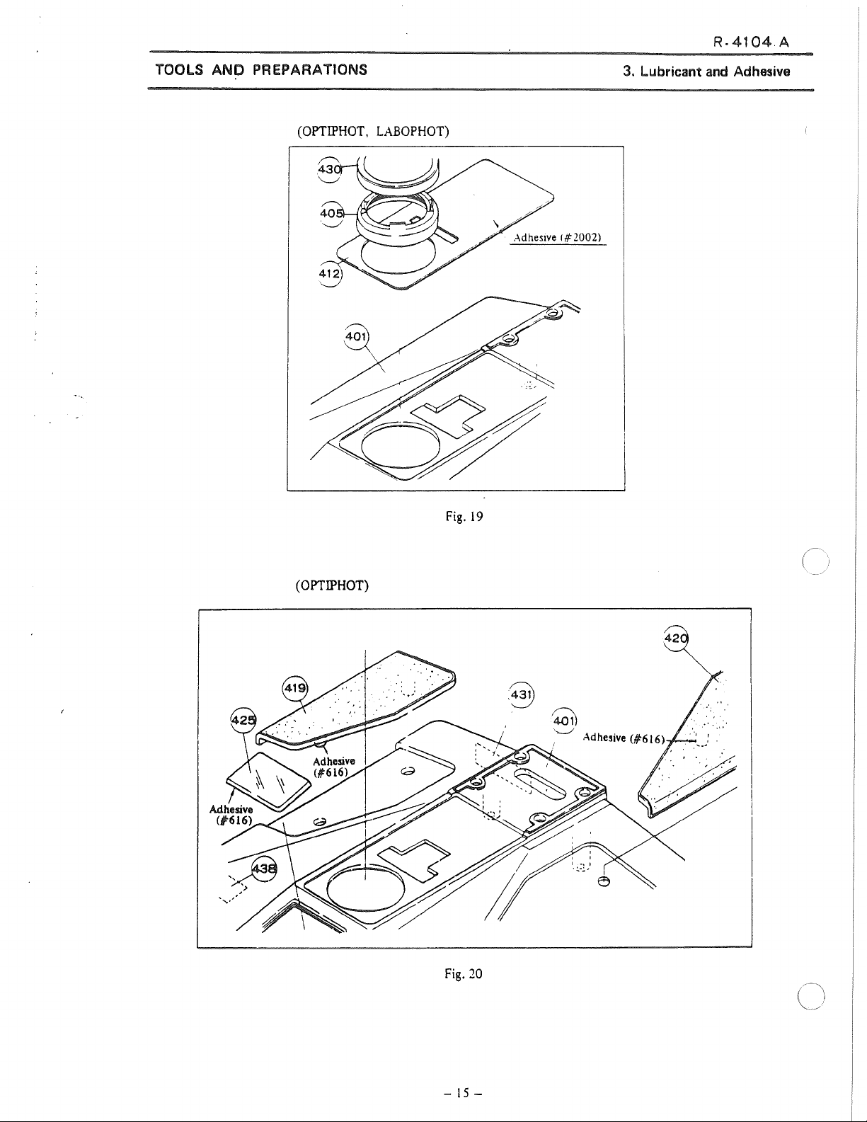
(OPTIPHOT,
LABOPHOT)
3.
Lubricant
and
Adhesive
(OPTIPHOT)
Fig.
19
'~
'..___./
Adhesive (#"616)
'
42
Fig.
-
15
20
-
Page 19

R-41
.A
TOOLS ANO PREPARATIONS
(OPTIPHOT)
i.--
~~
UJ
~)
Adhesive 1
(#2003)
'
1
1
1
"4s1\
~\
\.__./
Fig.
3. Lubricant and Adhesive
21
e~\
(LABOPHOT)
1
I
Adhesive (/F2003)/ 1
Fig.
22
t=:~
~~
i
1 \
-16-
Page 20

TOOLS ANO PREPARATIONS
(Lamp Housing)
3.
Lubricant
and
Adhesive
Lubricant (G605 3)
OPTIPHOT
X
jfsPl
~x2
'50
Fig. 23
50
'--..-/
-
17
-
Page 21
TOOLS
ANO
PREPARATIONS
R-4104.A
4.
Others to be Repaired
4. Others
111
Absolute alcohol
• Lens tissue
to
be Repaired
-
18-
Page 22

R.4104.A
MECHANISM ANO PRINCIPLE
MECHANISM ANO PRINCIPLE
1.
Coaxial Coarse and Fine Focus Unit
1. Coaxial Coarse and Fine Focus
Unit
1)
Transmission of turning
e Tuming force
shaft (
(@)
of
to
@.@.
e ln this transmission with
stage
the
offered by spring
e Thus,
almost
virtue
the stage.
and substage,
even
though
no
slack will
of
the rotation
the
move
®·
(e[!]))
some
force
of
fine
focus
the rack
@,@,
such
which
to
backlash
be
seen
force
Fig.
24
fine
focus
knob
knob (
C@D
(®)
vertically through
@,
a reduction ratio
exerts
force
the
sliding surfaces of @
is
provided
in
the
rising
and lowering directions of
of the
gears
work.ing
or
@>
@),@).
as
from
to
rotate @ ,
for
each
in
one
is
transmitted
the
gear
@
to
is
overcome
and
@ .
gear
to
enable smooth gearing,
direction under
to
system
@ ,
by the friction
the
the
pinion
(@
the
stage,
the
wetght of
, @ ,
weight of
by
-
19
-
Page 23
MECHANISM
ANO
PRINCIPLE
R-4104.A
1.
Coaxial Coarse and Fine Focus Unit
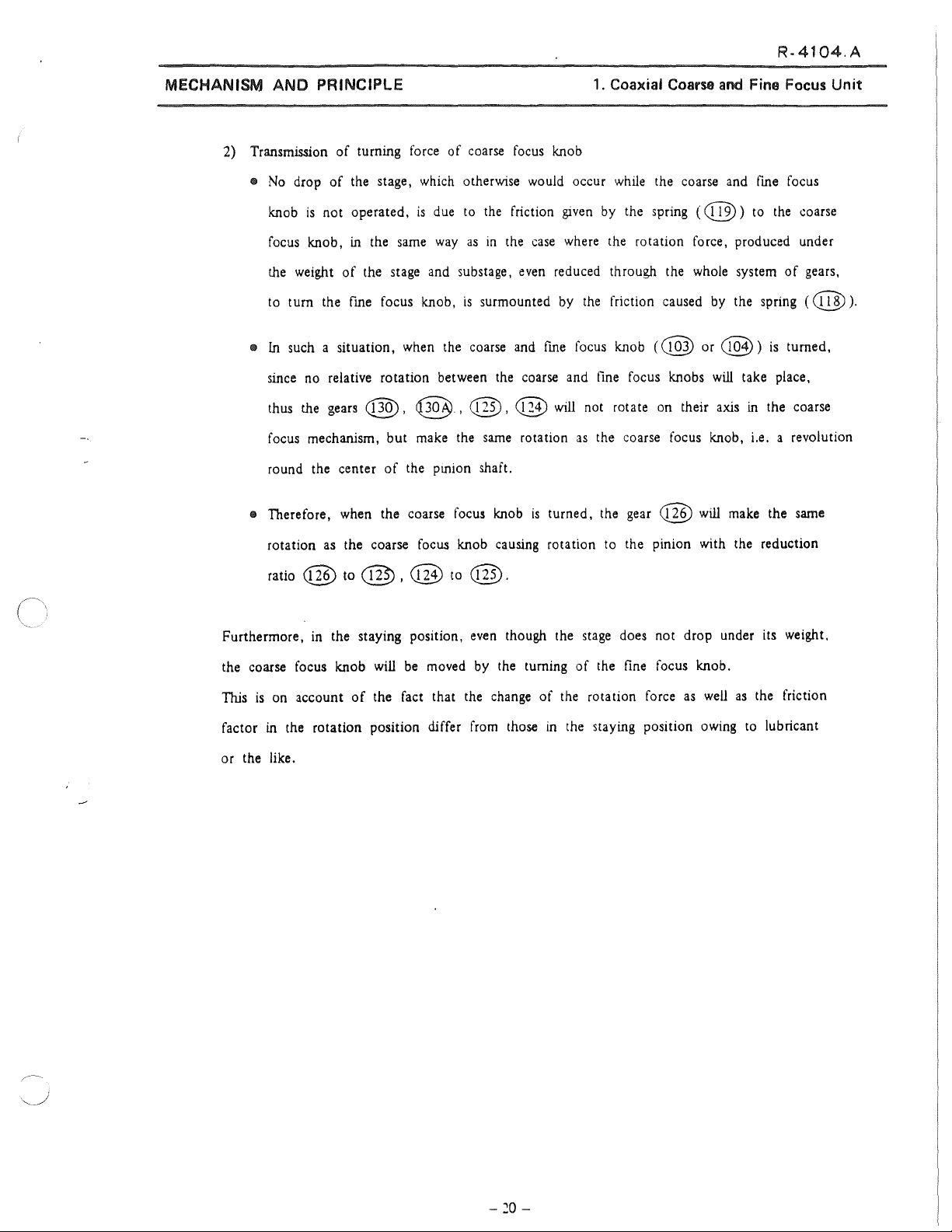
2) Transmission of turning
e
No
drop
of
the stage,
knob
is
not operated,
focus
knob, in the
the
weight
to tum the
• ln such a situation, when
since
thus
focus mechanism, but
round the center
• Therefore,
rotation
ratio @ to
of
the stage and substage,
fine
focus knob,
no
relative rotation between
the
gears
@.
of
when
the coarse
as
the coarse focus knob causing rotation to the pinion with the reduction
@,
force
of
coarse
which
otherwise
is
due
to
sarne
way
as
is
surmounted
the
coarse
@.
make
the pinion shaft.
@ to
@,
the
focus
@.
sarne
the
in
the
knob
focus
would
friction
the
case
even
and
fine
coarse and
@
rotation
is
knob
occur
while
the coarse
giVen
by
the spring
where
the rotation force, produced under
reduced through the
by
the
friction caused
focus knob
fine
will
not rotate
as
the coarse focus knob, i.e. a revolution
turned, the
(@
focus knobs
on
gear
@
(@)
whole
their
will
and
fine
to
the
system
by
the spring ( (@).
or
C@3)
will
axis
make
of
)
is
take place,
in the coarse
the
focus
coarse
gears,
turned,
sarne
Furthermore,
the coarse focus knob
This
is
factor
or the like.
in
the staying position,
on
account
in the rotation position differ
of
even
will
be
moved
the fact that the
from
though the
by
the tuming of
change
those
stage
does not drop under
the
fine
focus knob.
of the rotation force
in
the staying position
as
well
owing
its
as
the friction
to
lubricant
weight.
-
20
-
Page 24
DISASSEMBLY PROCEDURE
DISASSEMBLY PROCEDURE
1.
Coaxial
Coarse
R.4104.A
and
Fine Focus Unit
1. Coaxial
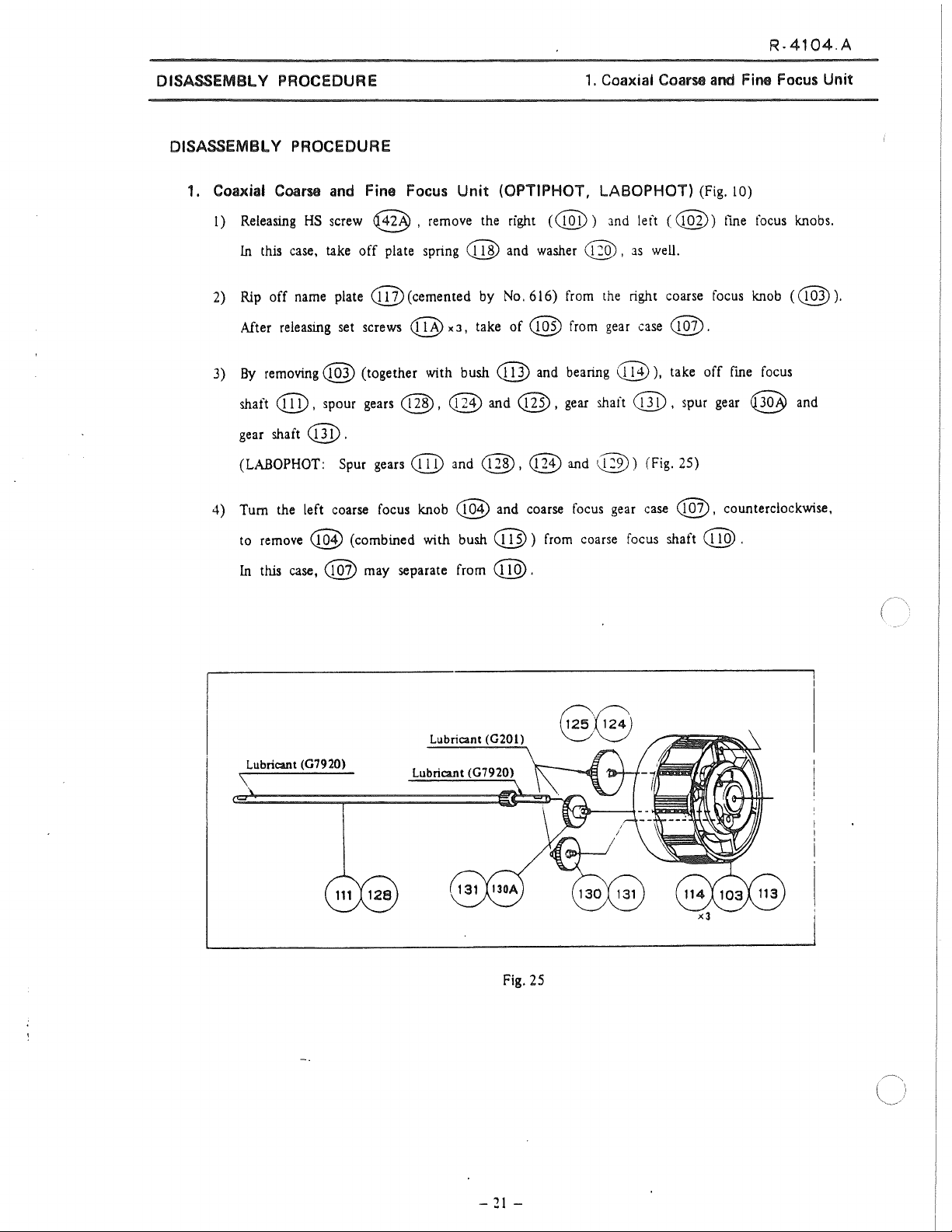
1)
Releasing
ln this case, take
2) Rip
After releasing set screws <@ x
3)
By
shaft
gear shaft
(LABOPHOT: Spur gears e@ and
4)
Tum
to remove @ (combined with
ln this case, @ may separate from e@.
Coam
off
removing@
e@
and
Fine Focus
HS
screw @ , remove the right
off
plate spring e@ and washer @ ,
name plate
(@(cemented
(together with bush @ and bearing
, spour gears @ , @ and @ , gear shaft @ , spur gear @ and
@ .
the left coarse focus knob
Unit
(OPTIPHOT, LABOPHOT) (Fig. 10)
(e@))
by
No.616)
J,
take
of
@ from gear case
and left
as
well.
from the right coarse focus knob
@),
@,
(@1)
bush@)
@ and
and coarse focus gear case
from coarse focus shaft
@)
(Fig. 25)
C@))
@.
take
off
@,
@.
fine focus knobs.
((@).
fine focus
counterc!ockwise,
Lubricant (07920)
Lubricant
(0201)
Fig. 25
-21-
Page 25

R-4104.A
DISASSEMBL Y PROCEDURE
5)
Draw
out
coarse
focus
6)
Remove
coarse
focus
shaft e@ . (Gears @ and @
bearing @
Adhesive <#350)
\ Adhesive
\
\
as
Adhesive (#
\
(#410
well
) Lubricant
616
B/M)
as
gears
e@
1. Coaxial Coami and Fine Focus Unit
will
come
in
sight.)
and
@.
(G7920)
(Fig.
26).
7)
Releasing
8)
Releasing
9) lmmersing the subassembly consisting of
alcohol, separate
Furthermore, take off thrust
@ can
(@
Note: Pinion
and
HS
bolts
PM
screw
be
taken out.
@
case
@x4,
@
coarse
are
cemented
<@ can
separate the
and
CM
focus
bearing @ .
loose
be
screw @ ,
stoppet' @ ,
wHh
e:ich
left attached on the
Fig.
arm
unit
remove
@, @,
and
oth.;r
uy
26
from
the
base.
rack
0 .
@,
[-íu.
main
@
and
@ into
then pinion @ and spur
ói ó) (Fig. 2ó).
body.
gear
-
21-
Page 26

R-4104.A
DISASSEMBL Y PROCEDURE
2. Subrtage Unit (OPTIPHOT, LABOPHOT) (Fig. 11. 12)
l)
To
remove the substage
(LABOPHOT:
First.
as
a unit, release clamp screw @ .
remove
rear
e o
ver
0 and substage body @
(j)).
2) After releasing
@.(Fig.
3) Pinion
4) After unscrewing
ª
(combined with
subassembly.
Condenser centering mount @ and dovetail @ having been attached
two
set
screws
28).
and
pinion shait @ can
bush
@)
PM
screw
(Fig.
28).
@ on
has
been removed. (Fig. 28).
'®
the
be
taken off, after condenser focus knob @
on the @ , remove the condenser carrier
bottom
of
@,
from
remove
2.
Subrtage Unit
rotler
race
pinion bearing
in
the correct
(mal e)
position,
arises. (Fig. 28).
using
the
tool,
it
is
not recommended
to
detach them,
so
far
as
no
problem
-
23-
Page 27
R-4104
A
DISASSEMBLY PROCEDURE
/~
204)
2. Substage Unit
2
38
A
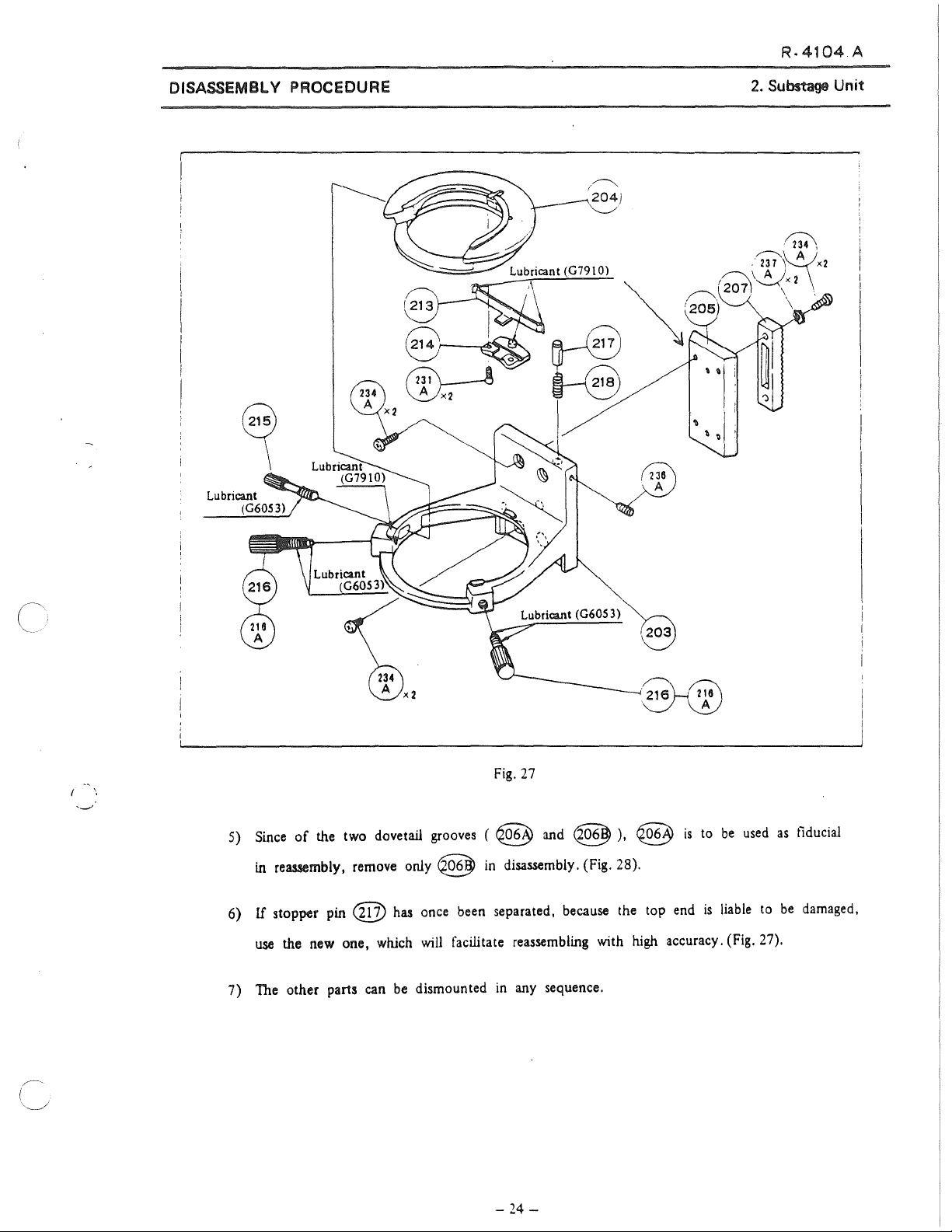
5)
Since
of
the two dovetail grooves ( @ and @
in
reassembly, remove only @
6)
If
stopper pin @
use
the new one, whlch
7) The other parts can
Lubricant (G6053)
Fig.
27
in
disassembly. (Fig. 28).
has
once been separated, because the top
will
facilitate reassembling with
be
dismounted
in
any sequence.
,203
~/~
·~
),
@
high
is
to
be
used
end
is
liable
to
accuracy. (Fig. 27).
as
be
fiducial
damaged,
-
24
-
Page 28

DISASSEMBLY PROCEDURE
Adhesive
(#"616)
i
---------
r
1----~202i
~
2 3 5 \
'~<3
~
' \
'---../
R-4104
2.
Substage Unit
A
~
\.Vx2
Fig.
1
28
-
25
-
Page 29

DISASSEMBL Y PROCEDURE
3.
Arm
Unit (OPTIPHOT, LABOPHOT)
!)
2)
3)
Releasing
Releasing
dovetail
Releasing
HS
set
HS
set
Q§j))
HS
screws
screws
screws
(Fig.
29).
@x4
@§3>
x4 (LABOPHOT:
@x4,
(LABOPHOT:
take
oif
dovetail @
@x4),
~
x4),
take
(LABOPHOT:
take off cover plate
oif
R-4104.A
3.
rear
coverQ.
Screw @ and
@.(Fig.
Arm
29).
Unit
Lubricant (G202)
Fig.
29
- 26 -
Adhesive
(#'616
Page 30

R-4104.A
DISASSEMBL Y PROCEDURE
4) After removing bottom plate @
CD
from
base
body @ . (Fig. 29).
5) Releasing screws @ and @ (LABOPHOT: @B
together with
6) Forcibly draw out roller
7) Releasing
(This@
In
this case,
reassembling,
re
tainer @
<
The
washers
screws
being cemented
<@ x
the
lefthand
remove
will
separa te.
disassembly described below should
from
@ - @ toward
race
(male) toward
J,
only
remove
to
(viewed
the
roller
main
body
from
righthand one.
CD
the user)
the base,
the
the
race
(female)
by
e@,
At
be
3.
and
base.
base.
releasing
and
(Fig.
(Fig.
@
29).
31).
'@
),
draw
x4,
take off ann
out
rack
@.
strike
it
with
a wooden hammer).
race
being
to
serve
as
fiducial in
this time, cylindrical roller @ and
attempted only
by
an
expert >
Arm
®
Unit
8) Nosepiece subassembly (only
Follow the sequence
i)
Remove
knob
ii)
Take off clamp screw
receptacle
main
ili)
Remove
to dismount clamp
nosepiece clamp
@.
body
E-ring
@
(D.
as
from
@
follows
pin
@ and spring @ .
iv)
Nosepiece clamp screw
@ and screw receptacle
@, though cemented
No.
by
unscrewed,
410 St/L, can
using
be
an
for
OPTIPHOT)
(Fig. 32 and 33):
Lubricant (G605
Adhesive
3)
(#410 ST/L)
ordinary tool.
Fig. 30
-
27
-
Page 31

DISASSEMBL Y PROCEDURE
9)
Release screws
off
the receptac!e 0 from main body. (Fig.
Cf!]>
x
J,
and by striking tube
Adhesive
(#646HB
receptade
31
).
6
R-4104.A
3.
Arm Unit
0 with a wooden hammer, take
Fig.
31
1
1
146\
~x3
h'40.
~1x3
-
28
-
Page 32

R-4104.A
DISASSEMBL Y PROCEDURE
4.
Base
Unit
(OPTIPHOT, LABOPHOT)
1)
Remove
2)
Releasing
take off
3) Releasing
4)
Remove
5)
Remove
@will
lens cap @ .
HS
screws
@ and @ (only @
PM
screws @ x
field
diaphragrn controlling
retaining
separate.
ring
@x4,
remove
for
base
@ and bottom plate
LABOPHOT).
< Field diaphragm (Fig. 36 and 37) >
2,
remove biade mount @ from bottom plate
ring
@.
@ , and then biade guide
way
4. Base Unit
@.
Beforehand,
@.
@ , biades @ and dowel
6) Take out lens
bottom plate
7) Remove retaining
@ and @
@(LABOPHOT:
@>
),
).
ring@
and spacer
@)
(LABOPHOT:
ring
@ (LABOPHOT:
G810
V.
Fig. 32
from filter receptacle
-@).
'<20 y
.<10
and then @ and @ (LABOPHOT:
@)
will
·~
/
e@
(LABOPHOT: From
separate.
-
29
-
Page 33

DISASSEMBL Y PROCEDURE
Fig. 33
R-4104.A
Base
4.
Unit
8) Take
9)
By
< Removing variable resistor
off
brightness contrai
removing the nut, variable resistor e® (LABOPHOT:
dial
e@
e§
and bush
(LABOPHOT:
@.
@)
@)
(Fig. 34) >
can
be
separated.
-30-
Fig.
34
Page 34

R-4104
A
DISASSEMBL Y PROCEDURE
< Removing mirrar @ and mirrar holder @ >
l
O)
After removing brightness indicator holder ( only for OPTIPHOT), take
@.(Fig.
35).
off
retaining ring
4. Base Unit
Fig.
_./
11)
Other
Note:
Washers
main
parts can
(@
body,
be
disassembled
-
@>
should be returned
xn,
in
any sequence.
used for adjusting slack, when attaching the base to the
to
their original positions.
-31-
35
Page 35

R-4104.A
REASSEMBL Y PROCEDURE
REASSEMBLY PROCEDURE
1.
Coaxial
1)
2)
3)
Coarse
Beforehand,
Applying
Apply
G7920
consisting
receptacle
and
clean@,
No.
616
of@
e@
to
to
@ at
and @ into pinion
to
@.
@.
4)
Clean
the thread of pinion
After drying, apply
Fine Focus Knob Unit
e@)
,
the
No.
@,
thread
the
position indicated
[n
this case,
case
350, and
of
pinion
@,
screw
@ -
shaft@,
case
make
using
in
coarse
1.
Coaxial
@,
in
@.
sure
gasoline.
focus
Coarse
@.
@
screw
it
into spur
Fig.
16,
and
Furthermore, attach pinion thrust
of smooth rotation of @
beanng
@.(Fig.
and
Fine Focus Knob Unit
usmg
tridane.
gear@.
insert
the
subassembly
and
36).
(
) Lubricant
--------'""--'-~~
5)
Insert the above subassembly into the arm. (Fig. 37).
616
Fig.
(G7920)
1
~
36
6) Inserting
screw @
arm
~ote:
e@ might
case, replace it.
by
rack
(V from undemeath
and
CM
screw
means
of
screws
be
scratched or deformed
@>.(Fig.
~
xJ.
the
arm, attach
38). After attaching,
(Fig. 37).
by
the
use
-
32
-
it
to the
of
a wrench,
bali
fi.x
race
pinion
when
by
means
case
@ to
detached,
in
of
PM
the
this
Page 36

REASSEMBL Y PROCEDURE
e~~~
'123f109 f 105 i 106)
. '--.__/
"-._/'
\.___./
1 •
; I \
1.
Coaxial
Coarse
and
Fine Focus Knob
R-4104.A
Unit
7) Attach
(this should
e@
8) lnsert the subassembly consisting of
shaft) and @ and @ (gears),
Fig.
9) Thereafter, following
fine
and @ should
Cover
washer
gears
are
10).
focus
plate @
@.
e@
and @
be
cleaned, beforehand)
to
be
oiled
as
4)-l ),
shaft @ ,
be
oiled
is
to
shown
gears
as
be
to
pinion
in
reverse
@ and
shown
cemented
Fig.
37
case
@ ,
to
e@
Fig.
36, after cleaned
e@])
(coarse
as
shown
the disassembly procedure. (After cleaned and dried,
@,
in
Fig.
24.
by
No.
by
in
@,
616.
means
focus
Fig.
and
37
e@
Apply
coarse
of
screws
and
case)
(apply
and @
G7920
focus
@x3.
dried.)
and
@ (coarse
oil
to
to
knob bearing @
e@
focus
@
as
shown
and
gears
@
plate spring e@ and
and
in
-
33
-
Page 37

REASSEMBLY PROCEDURE
2.
Substage Unit
R.4104.A
2.
Substage Unit
For reassembly,
1)
The
positions
only
2)
Rotation torque of
when
turning the pinion bearing @ .
(Measuring procedure:
After adjustment, fix the knob with
3)
If
in
have
reason,
position to
4) Check
reverse
the
specified lubricant
the knob
Disassembly
been
removed
it
will
use
for
smooth movement of the sliding parts
the
disassembly procedure, taking the cautions
to
be
oiled
the
condenser focus knob @
is
turned with pinion @ held by
Fig.
Process
(D
simultaneousty
be
necessary
the
specified positioning too!.
or
cemented should
:md
adhesive.
38)
set
(P.
24) both
for
for
finding the fiducial
screw
the
an
unavoidable
be
cleaned
is
the
@ .
dovetails
of
the
to
as
and
dried, beforehand.
be
adjusted
hand.
\1ake
below:
to
450g - 500g,
the adjustment
Tension gauge
Use
by
dovetails, without slack, unevenness or the like.
5)
Proceed to fitting of the rack
i)
Insert
set
screws
@x2
ii)
Attach the knob
üi) Attach
iv)
After releasing @ x 2 and inserting the dovetail, tum pinion bearing @ ,
lhe gearing of rack @
(utilizíng lhe eccentricity
v)
Make
slack, unevenness or the like.
rack@
sure of
to
to dovetail
no
clearance between @ and @ and smooth operation without
as
into the
@ with
is
achieved,
of
@
below:
@x
(male)@
main
body of substage.
2,
transitorily.
with
and
fix
).
@x2.
it
in
this position with @ x 2
Fig.
38
so
that
- 34 -
Page 38

REASSEMBLY PROCEOURE
R-4104
2.
Substage Unit
A
6) To attach the condenser mount follow the procedure
i) Attach spring retainer
ii) Insert plate spring @ between @ and
the arrow
ili)
Apply G79 I O
centering mount
in
Fig.
to
e@
to
condenser receptacle
Q8)
39.
the sliding surface
of
condenser
@ , and condenser receptacle
@.
iv)
Insert @ into
v)
Screw condenser clamp screw @ into @ through the opening
vi)
See
that
no
left condenser centering screws
operates smoo thly.
@.
seizure occurs between @ and @ ,
@
to
bring @
as
below (Fig. 27):
@)
with
.
Bend
the
when
to
the
screws
@ .
spnng
as
shown
Fig.
of@
manipulating right and
center, and @
2.
by
39
.
-
35
-
Page 39

REASSEMBL V PROCEDURE
3.
Arm Unit (OPTIPHOT, LABOPHOT)
R-4104
3.
Arm Unit
A
For reassembly,
l)
Clean
the
specified lubricant and adhesive.
2)
If
in
dismounted
the right and left races
3) Proceed to adjustment
i)
Fix
surfaces
ii)
Attach
attaching surfaces
using lubricant G202. (Fig. 40).
Apply lubricant G202
ili)
of
reverse
and dry the parts to
Disassembly Procedure 7
for
@x4
of
the disassembly procedure, taking the cautions
an
unavoidable reason,
to
@,
@x4
<@ , @ and cylindrical rollers @ .
be
oiled
(P.
22)
have
not been dismounted).
of
the
roiler
the
guide
rails
@ attaching
using
lubricant G202. (Fig. 40).
to both the guide
of
roller
race
to
the sliding surfaces
or
cemented
the
use
races
rail
(male)
as
lefthand
the right one
as
race@
below:
@
G),
as
below:
shown
in
Fig.
29, 30, and then apply
on
the fiducial
as
fiducial (Assuming that both
G202
Fig.
40
side
has
G202
8
been
'
'-·
Place cylindrical rollers @ and retainer @ onto the surfaces of e@ .
iv)
time, insert @ one after another
Assemble
v)
As
vi)
in
Set it with <@
vii)
cementing agent No.
~
(j) and
shown
this position with <@
at
six
@,
in
Fig. 21, pushing
x6,
350 into
points.
transitorily.
and
xJ.
inject
in
tum. (Fig. 29).
@,
adjust the torque of (j)
to
IOOg
Fig.
At
- l 20g. Fix
(Iorque mearuring)
fiducial
ooe
41
this
it
- 36 -
Page 40

R-4104
A
REASSEMBLY
4.
Base
Unit
For reassembly,
cemented (Fig.
or adhesive should
PROCEDURE
reverse
32
- 35)
be
applied.
the disassembly procedure, remembering that the parts
are
to
be
cleaned and dried, beforehand,
and
the specified lubricant
to
be
4.
oiled
Base
or
Unit
- 37 -
Page 41

ADJUSTMENT
ADJUSTMENT
1.
Torque
1)
Referring to Reassembly Procedure
washer e@ and adjusting washer e@
as
After screwing coarse focus knob @ and bush
of
Coarse Focus Knob
shown
in
Fig.
42, into coarse focus shaft
(P.
32), insert
in
sequence,
(@.
2. Smooth
wave
1.
Torque
of
R-4104.A
of
Coane Focus
the
Left
Fine Focus Knob
iº.
01121
Knob
(
__
@ into
400g -
2)
When
focus knob
Applying adhesive
to let the adhesive enter
2.
Smooth Turning of
1)
Referring to Reassembly Procedure
and insert the washer into
into
@
,
that the thrust slack
@,
SOOg,
a correct torque
e@
),
and set it with @ in such a position
make
adjustment of the torque
by
means of washers @ , @ .
is
obtained, disassemble coarse
(®
and bush e@.
No.
410
to
the thread, tlx @ and @
the
internal surface of @ .
the
Laft Fine Focus Knob
(P.
fine
focus shaft e@. Then, insert left
(beforehand, place set screw
of
the knob
is
not felt by
32), attach G7920 onto both sides
~
into
to
in
position.
Fig.
42
Be
of
washer
fme
focus knob @
careful not
@,
touching with the
li
2)
Make
sure
C@1)
and @ , and their smooth tuming.
fmger.
of
seizurc between coarse focus knobs
- 38 -
Fig.
43
Page 42
AD.JUSTMENT
3.
Smooth
!)
Referring
4.
Parallelism between the Tube Attaching and Stage Attaching Surfaces
3.
Turning of the Right Fine Focus Knob
to
Reassernbly
Procedure
(P.
32), insert right
Smooth
fine
R-4104.A
Turning of the Right Fine Focus Knob
focus
knob
C@D
into
fine
focus shaft
right
torque of
2)
Make
@
and
fine
sure
and
coarse
e@
(beforehand,
focus
knobs inwards,
30g - 40g
of
no
thrust slack felt
right
coarse
focus
knobs.
place
set screw @ into
fix
thern
in
such positions
is
obtained. (Measuring procedure:
by
touching with t
focus
knob
@.
Also, check
C@D
).
by
rneans
Fig.
38).
he
finger
and
for
smooth tuming of the
Pushing
of @ , that a
no
seizure
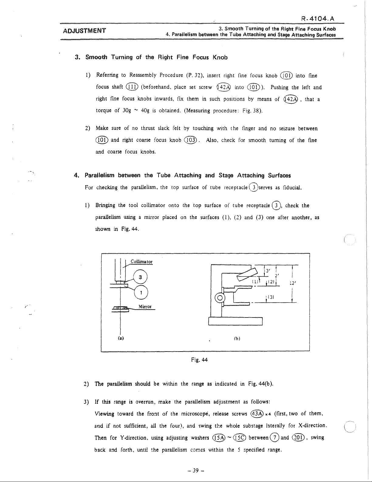
4. Parallelism between the Tube Attaching and Stage Attaching Surfaces
For checking the parallelism, the
1)
Bringing
parallelism
shown
in
the
using
Fig.
too!
44.
collimator onto
a mirror placed
top
surface of tube receptacle (})serves
the
top surface of tube receptacle 0. check the
on
the surfaces
(!
),
(2)
and
as
fiducial.
(3) one after another,
the
between
left
and
fine
as
12'
/
(a)
2) The parallelism should
3)
lf
this
range
Viewing toward
and if not sufficient,
Then
for
Y-direction.
back
and
forth, until the parallelism
~irror
is
overrun,
the
be
fro=it
ali
using
Fig.
44
within the
make
of
the microsccpé, release screws
the
four),
adjusting
range
as
indicated
the
parallelism adjcistment
and
~wing
the whole substage
was.hers
c::imes
@ - @ between (j)
vtithin
(b)
in
Fig.
as
foUows:
<@K4
the
5 >pecified range.
44(b).
l1teraHy
(flrst,
and
two
of
for
X-direction.
@ ,
them,
swing
- 39 -
Page 43

R-4104A
ADJUSTMENT
5. Centering
To
perform the centering,
5-1.
Using
1)
Place
Fig.
the part @ onto the stage attaching mrface
of the substage. (Fig.
2)
Push
above.
proves correct centering.
3)
If
upper screws
so
5. Centering
the
Tube
Attaching and Stage Attaching Parts
use
the three
the tube receptacle substage centering tool 125142.
the part ®
2 (P. 3) on the tube receptacle 0·
the part
If
the former enters
not, make adjustment,
that the
of
the tool,
45)
@)
against the part @ from
the
using
of
~
•4
behind the arm,
part@
enters the part
as
latter,
the
to
shown
two
@.
ois,
it
in
Set
the
as
Tube
foilows:
Attaching and Stage Attaching Parts
Thereafter, make parallelism adjustment,
using
the lower two screws.
(
(
4) Smooth insertion
range
as
shown
5-2.
Using
substage rightangle/centering too! 125145 and 125143,
between the objective attaching and stage attaching surfaces.
1) Set tool 125145 onto the objective attach·
ing
surface to
the stage attaching surface.
Raise
2)
3)
the substage to
of
125145
and
Y directions).
If
it
is
found over l/IOOmm, make the
sarne adjustment
(P.
39), until it comes within the specified
of
in
be
checked.
is
smaller than
as
the part @ into the part @ ensures the parailelism within the
Fig. 44(b ).
Place
125143 on
see
that the clearance
1/1
OOmm
(in X
mentioned above
in
4.3)
to
Fig.
45
check the parallelism
range.
-40-
Fig.
46
Page 44

ADJUSTMENT
5-3.
Using positioning tool 125141,
As
1)
of
to
check the position
shown
in
Fig. 1 (P. 3), bring the
the tool onto the condenser attaching
part@,
5. Cantllring
6. Cantering
of
the
Tube
Attmching and Stago Attaching
of
OptiCllll
substage and condenser mount
System in
the
R-4104.A
Paru
Microscope Base
surface, and the
attaching surface.
2) Raise the condenser attaching surface to
make sure that the part
part
@.
3)
If
it
does not, make adjustment by
means
of
6. Cantering
6-l.
Using tools 125146 (for OPTIPHOT)
1) Take
125146. (Fig. 48).
2)
Set the above cited collimators on the specified
positions on the
of
off
the lamp housing, and set the too!
part@
@ enters the
@
x4.
Optical System
base.
onto the stage
in
the Microscope Base
Fig. 47
,.·
Elimina te any slack, if takes place, by means of
washers.
3) Bringing the part
without the lens, make sure
positions
collima
4)
If
@
5)
P1ace
Viewing the position
to the center by means
of
tor. (Fig. 49 ).
the positions are
x:i,
provided for attaching mirror mount
the part
@CFig.
the filament
not
@onto
of
6) onto the position
of
the correct
(G))
and mirrar
found coincided, make adjustment by means
the positfon with the lens.
the field diaphragm through the eyepiece, bring the diaphragm
of
screws @ x 2 provided for attaching biade mount
125146
(@),
viewing through the eyepiece
@.(Fig.
32).
Fig.
of
48
screws
of
@.
~.
;
-41
-
Page 45

R.
4104.A
"
ADJUSTMENT
6)
If
or
ln
7)
Check
the
6. Centering
the
field
díaphragm does not come to the center, incorrect positioning
filament
this
field
is
conceivable.
case, correct their positions, and proceed to 3)
the minimum
diaphragm.
(less
than lmm4') and maximum (more than 35.9mm4') díameters of
J 25146
~)'~
~
'-;/
of
Optical System in
and
6)
again.
~
4221
.___/
125146
the
Microscope Base
of
the mirrar
11
@,
(P.
_1j
Fig.
@,
and set
41
).
49
the
tool 125147. (Fig. 49).
(
6-2.
Using
tools 125147 (for LABOPHOT)
!)
Take
off
@.
@,
2)
Refer
to
2)
- 7)
of
6-1.
0
\ '
~/
Fig.
-42
125147
50
-
Page 46

.A
ADJUSTMENT
7. Tube Length
1)
Attach the part @ of tool 125148 (Fig. 8) (P.
®
2)
Attach the trinocular eyepiece tube to the part
Using
3)
In
lf
until the
to
the nosepiece, and the part @ to the
the
20X
eyepiece,
this case, the colors should
not, rotate cover
sarne
colors
see
the interference colors
be
the
ring
e@])
(beforehand, dissolve
are
attained. Cement @ agam,
sarne
as
5)
to
the
tube attaching part, the part
stage
a ttaching surface, respectively.
@.
in
the
grating of
those
viewed
No.
through the vertical tube.
350
by
alcohol)
using
No.350.
7. Tube Length
the
part
of
the tube,
@.
-43
-
Page 47

.4
04.A
ADJUSTMENT
8.
Adjustment
!)
Tum
2) Fully tum (
of
Brightness Control Circuit (Fig.
off
the power switch 5
~
) the shait of variable resistor
(
~
1
).
8.
Adjustment
51,
52)
VR
in
3
of Brightness Control Circuit
the
DC
ammeter M
(
1
@),
counterclockwise.
3) Fully tum (
~
) the shait of variable resistor
VR
(e@
1
)
in
the printed circuit
counterclockwise.
4)
Change
5)
Set the power voltage to
'
..
6) Connect the thermostat·type voltmeter (
the terminal
over the power change-over switch Sl (
of
the lamp.
AC 1 OOV
± 1
%,
over
5
Hz.
l
.5
~
class)
)
to
AC 1 OOV.
for
measuring the
lamp
voltage
to
7)
Plug
the power source cord into the socket.
lamp
After connecting the halogen
of l 2V,
SOW
with the lamp socket.
(
8) Tum on the power switch S
Do
not tum the power switch
ON
(at a maxirnum voltage
ln
this position the brightest illumination will
9) Slowly
tum
thP.
shaft of
and then the illumination
Stop this tuming at the position where the lamp filament looks dim.
Do
not
tum
the shaft beyond this limit, because the lamp
10) Tum the
variable
dial
resistor
of
power switch S
(
VR
@ ) becomes lower, until the thermostat-type voltmeter
2
indicates 9.0V.
(
~
1
dial
of
variable resistor
variabie
oi
the
1
).
beyond the position where the swttch
VR
(
~
).
)
in
the printed circuit, clockwise,
will
glow
in
which the voltage
res1stor
lamp
(
~)
will
1
be
obtained .
...--...
VR
(
~
1
be
slowly darkened.
in
the direction
is
just turned
suddenly.
of
11) Tum the shaft
so
that the
DC
of
variable resistor
ammeter M
(@
1
(
VR
~)
3
) indicates 9
-44
-
for sensitivity adjustment, clockwise,
.OV.
Page 48

AOJUSTMENT
12)
Tum the
M
1
In
13)
If
dia!
of power switch S
@ ) minimum.
(
this case, the voltage
the
DC
ammeter M
of
variable resistor
C@)
1
(@)
1
indicates a
8. Adjustment
to
make
the indication
VR
( @ )
2
value
not higher than 1.8, tum
will
of
Brightness Contrai Circuit
of
DC
ammeter
be
maximum.
the
shaft of
variable resistor
a higher
value
value
within the
14) Fully tum the
the lamp and
over 11.5.
VR
(@
)
in
the printed circuit, counterclockwise,
than 2.5, slowly tum
range
1.8
- 2.5V.
dia!
of
power switch S
swing
of
the needle in
and
if
the
shaft clockwise, until the meter indicates a
1
the
(e)
DC
to
make
ammeter M
sure that the brightness
(
@ ) changes smoothly
1
it
indicates
of
- 45 -
Page 49

UIMB
111MB2(
(
125
250V-
·,
l>
E
e
~
s:
m
z
V-
4A)
2Al
~
.&:.
°'
1
,... L
J\
1
\
l
{
1 ;,<
o
'"O
-1
='3
:e
o
-1
1004
)
CIO
l>
Q.
e
~
3
<111
::J
....
o
-
CD
:=!
.
<C
::T
....
:::s
<111
~
n
o
e:.~
IOOl
111MB
(
~
)
_"'
( ª:f)
(-{(~')(<
~~t(llrown)
(
1002)
1
-.
Whuc
\
1.
(
·n
'-
N ,
F 1 Brown
Grccn
J)
11~--y+.
"Jl
ciQº
Vo
( 1018)
(i~)
(IA)
MB2(0
l5~J
...
)(~)
('"') / -
IOOG
/ 8
111MB (
Jll
MB2!2" / 2<0VJ
I / / - \
s
1
fl
D
I\
1
'
C A
. s
Whnc
IOOV
l20V
2
or
220V
tlllack)
\
\
or
\_
_____
240V
(Wlutc)
llluc
4V
70mA
(
1012
\ _
r Y'\: D
(Whllc)
Ul20
(
---
100/i20V)
~oo0 _ ~OKl
)
~---------
~
e;.:)-
0o·0
\
Rcd 1 IGrccnl l 1
1
A M, -
(~
_.;;,
nluc
•"
/·--
'~)
(•~20)
P11n1cJ l.JíLUll l>u.uú \ ---
--
----
(·~~)
(·~9)--
(
·~·)
F)
---
\
l:Uuc
liluc
(um\
.
8)
(•~_-)
(~~
(
wm)
( 1014)
lµ
l_
. -
----~--
(1100)
- -
-\------
(1~6)
~
(
'ºt1)
-
I
íay
--i
~
1~
o
.$:>.
- .
Q
..
o
....
=·
l
l>
Page 50

ADJUSTMENT
112MB ( 100V) LABOPHOT Y
~
A1
'-..__/
'~
'
1013
1
','---/
QI
\'-...__,,/
.~
~(
r~,
~}
1002
)
\
\.~
'-..__/
F1
BrownlS1 Brown
Cf/!
D
l20V i
White
lOOV
~
I,~
T1
9V
\ i
,~
/
'------
'
C A
ov
Black
Black
~
112M81 C120Yl
3.3A
Red
Red
8.
Adjustment
'~
1005
,1
'----._/
D1
- t
of Brightness
'~
·~·
~)
Red
/
~
Contrai
®
; Brown
®
Circuit
~
,..~
_,
CV
8~6
\..
112MB2
\ 1
\ \ 1
\ 1
\ J 1 White J
W1\ i '
(220 /
24-0Y
IOIMI
White
2
,
L_
>
~1
\ 1
\ \
__
----
Black
!'·
0)
C!)
8
®
t
3.3A
Red
i
1
®/
(
--
--
_____
_/
1015
8
Brown
/ C A
L_
______________
Black
- 47 -
---·
,~/
\JU;
,
1
1
__
_/
Brown
®
Fig.
52
Page 51

R-4108.A
TOOLS ANO PREPARATIONS
TOOLS ANO PREPARATIONS
1. Tools for General
Use
Item
4 + screwdriver
- screwdriver set
6
set
Tweezers (Stainless steel)
Blower
Handlap
Hexagonal spanner
+ Screwdriver with
wood handle
Plastic hammer
1. Toais for General
Used
Screwing
1
Oeaning
Containing absolute alcohol.
Hexagonal socket head bolts (
Set screws
3 and 2.6mm screws ( conical
potnt)
Giving sharp knock
in
general
"
(3, 4mm)
for
3,
4,
5,
pomt and
Use
6mm),
oval
2. Exclusive Toais
2. Exclusive Tools
Item Tool No.
l
Smm
grating micrometer
Microscopes stand with
IOX
40X
objectives
Kellner eyepiece
Tension
Box screwdriver
Torque adjusting too!
• Torque adjusting tool
gage
Used
for
128004 Checking perpendicularity, straightness
of
movement
Adjustment
in
general
128006
Measuring torque
121060
121061
Hexagonal nuts
Round nuts (
(4mm)@
15) \ 16)
(Fig. 1)
Fig.
1
Page 52

R-4108.A
TOOLS ANO PREPARATIONS
3. Lubricant
1
4. Adhesive
Item
G6053
G7910
G7866
Item
#'410
N/L
Stage
base
Pinion
bearing
pinion
@.
@ .
Wave
Spiral spring @
Stage
upper plate
@,
Pinion
Y pinion @ and Y axle (screw).
plate(
~
Wave
washer
cover@
for
üsed
2)
and clamp
and
was.her
@
Used
Q,
stopper @
screw
@inion
17
and
and
Delrin
for
and pinion bearing @,
3. Lubricant 4. Adhesive 5. Others
( 42).
@.
Y
Delrin
washer
was.her
and
@ .
screw
5. Others
• Absolute alcohol (ethanol or methanol)
•
Lens
tissue
Page 53

DISASSEMBLING PROCEDURE
DISASSEMBLING PAOCEOURE
1)
2)
3)
Detach the
Releasing
Removing
the
slide
holder assembly
the
screws
the
screws
spiral spring @
@x
@separate
from
the holder
2
remove
from
the
stage
the
holder metal @
the
slide
glass
metal
@. (Fig. 2)
releasing
the
flxmg
screws
from
the
retainer @ together with
39
holder
x
2.
(E).
the
washer
R-4108.A
@
and
4)
5)
6)
7)
8)
9)
10)
11)
Releasing
Removing
Remove
Remove
Remove
Remove
Remove
Remove
Fig.
2
the screws @
the
screws@><2
the nut @
the X knob @.
the
wave
washer @. the
the round nuts
the
wave
washer@
the Y pinion @ and Y knob @ assembly.
..
2.
of
the
X (right
@@
remove
of
the
of
and
the
the
pinion
and
Delrin
the
Delrin
rack@
cover(V
left)
washer@
Y (to
and
washer
knob
fro) knob
(Fig. 4).
separate
@.
and
the tlat washer
@.
the
@.
handle assembly
@.
from
the
stage.
-4-
Page 54

R-4108.A
DISASSEMBLING
12) Remove the beirin washer @ .
13) Remove the X
PROCEDURE
pinion@@
together with the Delrin
washer@
. (Fig. 3)
14)
Releasing the
(Fig.
4)
15) Releasing the screws
At
the sarne time the X block
also separated.
16) Remove the X
17) Separa te the guide block either @ or
plate
0 the
screws@x2,
@x4
rack@
rollers@,
separate the vernier scale
separate the X guide
(D.
the
from the X
the
retainers(Z)
block(D.
Fig. 3
seat@
block@
rollers@
@.
the
retainers(V
from the stage upper pia te
and the guide rails @ becomes free. (Fig. 5)
from the stage base
from the Y guide blocks @ ,
and the guide rails
G).
Then the stage base
plate(3).
@@
@.
are
-5-
Page 55

DISASSEMBLING PROCEDURE
Fig.
R-4108.A
4
Lubricant (G60S 3)
Fig.
-6-
5
Page 56

DISASSEMBLING PROCEDURE
R-4108.A
Fig.
-7-
6
Page 57

REASSEMBLING PROCEDURE
REASSEMBLING PROCEDURE
R-4108.A
< Reassembling
1)
Put
@ inserting its inner
2) Insert the outer
3) Keeping the spiral spring, the inner end
the
Slide Holder >
the axle supporter @ on the slide holder metal @ .
and
into the
and
of the spiral spring @ through the
C A)
pin
hole of the metal @.
Fig.
7
in
the
pin
hoie, tum the washer @
Place
pin
hole of the
the spiral
(
8)
spring
washer
in
@
on
@.
the
arrow direction
the
metal
(A) and to
Then, place the slide
into the pin hole
4)
Fix
the above slide
be
positioned
as
shown
glass
retainer @
of
the retainer @
glass
retainer assembly
by
(B)
over
and
in
Fig.
7.
the washer @ inserting the spiral spring outer end
fasten the screw
Fig.
8
on
the holder @. The latter
@.
(Fig. 8)
is
to
be
attached
to
the stage.
-8-
Page 58

REASSEMLBING PROCEDURE
R-4108.A
< Reassembling the Handle > (Fig.
J) 1nsert the X pinion with the axle
pinion bearing
Placing the washer @
Lubrica.~
2)
Fit the assembly
washer@.
3) Put the Delrin washer @ x
in following order: @ -+ @
4)
Screw on the
bearing. The turning torque
5) Put the tlat washer
the following order: @ -+ @ - @.
6) Screw on the X
7) Put the
@ .
in
@CD]) with the
of
the Y pinion @ and the Y knob @ to the bearing @ inserting the
round
nut
@ and the lock nut @ to the bearing @ to hold the Y knob
@,
knob
@ to the axle (@.
washer@
and screw on the
between.
oi!
1,
the
of
the Y knob
the wave washer @ and the Delrin washer @
9)
(§>@
G7910 and @ wtth the oil G7920.
wave
...,.
@ .
into the assembly
washer @ and the tlat washer @ x 1 on the bearing @
is
to
be
adjusted by means
nut
@ to the axle
of
the pinion
@.
of
these nuts.
cover(V
on
the axle
and the
on
e@
the
in
The tuming
torque
of
the X·knob
is
to
be
adjusted by means
of
the
nut
@.
r;~·.
Fig. 9
-9-
Page 59

REASSEMBLING PROCEDURE
R-4108.A
< Reassembling
1)
Place the stage upper
whichever that has been left fixed on (j) makes the basis
Place the rails @
on the groove
2)
P1ace
rollers and retainer
oil.
Place the guide block @
guide block
3)
Make
plate(D
If
any slack
that has been just reassembled by the procedure 2).
me
X
the stage
and Y Movement
pia
te
Q upside down tilting on a table. The guide block @ ( or @ )
x2
-+
the
rollers@x4
of
the guide block @ .
baseplate@
@
on (D facing its rail groove to the
x2
-@x4
e@)
-(})x
on
CD
> (Fig.
@ to the upper plate Q by screwing the screws @ x
sure that no slack
on the base plate
is
found, release slightly the
in
the X direction
{]).
screws@
s.
6)
.
of
the reassembling.
.....
the
retainer(Dx
1 on the other rail groove
facing its rail groove to the rail groove
is
found at the both end of the moving range
xJ
1 lubricating with lubricant G202
rail
groove
of
@ . Put the rails,
ofG)
applying G202
J.
to adjust the guide block @ (or
of(D.
Fix the
of
the upper
@)
4)
P1ace
the whole stage assembly tilting on the work table
upperside.
@x2
Put
5) Apply
one rail groove
Put@x
6) Put @
Then,
7) Fix the vemier scale @ and its
8) Fix the handle assembly to the guide block @ or @ and adjust the meshing
the X rack
-•{V•4
G202
oi!
ofÜ
4 -(V. 1 on the other rail groove
x2
on 8 rail groove applying G202 oil and place the latter to
fix@to@,@
@ releasing the screws
-(2),.
to
the both rail grooves
faces to the groove
1 on the above groove applying G202 oi!.
screwing the
seat@
@x
ofG)
on which put @
of(D.
of@.
screws@x4.
to the stage
2 slightly.
soas
the X rail groove
base(D
x4,
then place 0 on
face
by the
screws@
of(D
the groove
is
on the
G)so
ofO.
x2.
of
the pinion and
as
1
J
-10-
Page 60

REASSEMBLING PROCEDURE
9)
Pl.ace
10)
the Y rack @
ing
the
screws
@x
Attach
the slide holder assembly to the stage.
on
the stage base (D and adjust the meshrng with the handle assembly releas-
2 .
R-4108.A
-
ll
-
Page 61

REPAIR ANO AOJUSTMENT
1. Failure of the Slide Glass Retainer 2. Slack
3. Wobbling
of
the
Slide Glass Retainer and
of
the
Slide Glass Carrier
the
Slide Glass Carrier
R-4108.A
'··
REPAIR
1.
ANO
Failure
Cause: (1)
AOJUSTMENT
of
the
Slide Glass Retainer
The
yielded
(2) Looseness of the
or
disengaged
small
t1at
sp1ral
head
spring @.
screw@.
< Repair and Adjustment >
(!)
Exchange
Procedure j
,,
i)
Disassemble the retamer assembly following the procedure
ü)
If
it
ili)
Check the function of repaired retainer.
the
the spring
correctly
yielded spiral spring @
is
yielded replace
foilowing
the reassembling proced.ure (P.
it
with a spare, and if
or
hook the disengaged spring
2),
the
spring
7).
to
the
pin
hole.
3)
(P.
5).
is
disengaged, reposition
(2)
If
the small ílat
function.
2.
Slack
of
the
Slide
Cause: Looseness
< Repair
3. Wobbling
Wobbling in X direction: Refer
Wobbling
and
Fasten
of
in
Y direction:
Adjustment >
firm
the
the
Slide Glass Retainer and
Gim
of
screws
head
screw
@
Carrier
the
screws
@
@ .
Make
to
the
following chapter 4.
Refer
to the following chapter
is
loosened fasten
sure
that
the
no
slack
Slide
5.
is
Gim
it
firm
found.
Carrier.
and check the retainer
·~)
-
12
-
Page 62

R-4108.A
REPAIR ANO AOJUSTMENT
4.
Wobbling in X (right
Cause:
(!)
Slack, sticking, squeezing in the X
a) Inferior meshing
b) Dent on the X guide rails @ , @ , the
and
(j).
e) Dust, soil, scratch on teeth
(2) Looseness
< .Repair
Procedure
and
(!)-a)
Adjustment >
If
the rack @ and pinion @ rneshing
and
pirúon.
4. Wobbling in X {right
left) Movement
gu1de
rail assembly.
of
the rack @ and the pinion
of
the rack @
of
the screws @ or inferior adjustment
is
and
left) Movement
@.
rollers@
or
inferior adjust the position
or deformed retainers
the pinion
of
@.
the X guide
block@.
of
the rack
i) Detach the slide holder assembly from the stage.
ü) Releasing the
bloclcs @ , @ .
Then,
rails
@ , @ will be rnade free simultaneously.
üi) The rack
iv) The pinion @ position
v)
Follow
vi) Check
screws@x4
the X movement
block(D,
@ position
the
reassembling procedure.
the
rack
and
pinion rneshing and the wobbling in the X rnovement.
separate the X guide
the
rollers@,
is
to be adjusted slightly releasing the screws
is
to
be adjusted slightly releasing the
block@from
the
retainers(Z)
the Y guide
and the guide
@x
screws@
2 .
•
2.
-
13
-
Page 63

R-4108.A
REPAIR
ANO
ADJUSTMENT
(1
)-b)
Procadure
i)
ii)
ili) Follow the reassembling procedure.
iv)
(i)-c)
If
a~y
dent
is
found on the
(})
is
deformed, replace them with spares.
Foilow the procedure i),
Replace
Check wobbling
Dust
brush
lf they
dented or deformed parts with spares.
in
the X movement.
or
soil
on teeth
or
cleaned by gasoline.
are
ínjured, replace them with spares.
of
the rack @
guide
ii)
of
4.
rails
@ , @ ,
(1)-a).
and
Wobbling in X (right
the
rollers@
pinion
e@
are
to
be
and
left) Movement
or if the retainer
removed
by
a
Procedure
í)
ii)
iii)
iv)
v)
vi)
vii)
viii)
Follow the procedure
Remove
Remove
the rack @ releasing the
the handle assembly releasing
i)
of
( 1
)-a).
®·
Follow
the
procedure
Follow the disassembling procedure
Remove
spares.
Follow the reassembling procedure.
Check wobbling in the X movement.
dust and
soil
ii)
by
of
the
a brush
above
or
screws
the
( 1
6)-13)
clean
@ x
screws
)-a).
by
2.
c@x
(P.
4).
gasoline. Replace injured parts with
2
of
the pinion cover
-
14-
Page 64

REPAIR ANO ADJUSTMENT
4.
Wobbling in X (right
5.
Wobbling in Y (to and fro)
R-4108.A
and
left)
Movement
Mov11m11nt
5.
Wobbling
(2) Loosened screws @
readjusted.
Procedure /
Slightly releasing the screws
X movement.
in
Y (to
and
Cause: (
l)
Slack, sticking, squeezing
a)
Inferior meshing
b)
Dent
G).
e) Dust,
are
to
be
tightened
@x
2 adjust the G position and check wobbling
fro) Movement
in
the Y guide
of
the rack @ and the pinion @ .
on the Y guide rails @ , the
soil
or scratch on teeth
of
the rack @ or the pinion @.
firm
and inferior position of
rai!
assembly.
rollers@or
deformed retainers
(D
is
to
be
in
the
< Rapar
(1
Procedure
(2) Looseness
@
(or@).
and
Adjustment >
)-a)
If
the
rack@
i)
The rack @ position
ü)
Check wobbling
of
the screws
e§
and pinion @ rneshing
is
to
in
the Y rnovement.
or inferior adjustment
is
inferior adjust their position.
be
adjusted slightly releasing the screws @ •
of
the Y guide block
2.
-
15
-
Page 65

REPAIR ANO· ADJUSTMENT
(1
)-b)
If
any
dent
is
found on the guide rail @ , the
5.
Wobbling in Y (to
roUers@
or
if
the
R-4108.A
and
fro) Movement
retainer(2)
is
deformed replace them
Procadure
i) Detach the slide holder assembly from the stage releasing the screws @ x
ii)
Remove the
iü) Remove the handle assembly releasing the screws @ x 2
iv) Releasing the screws
blocks
retainers
v)
Releasing the
another
plate
vi)
If
any
(2)
is
vii) Follow the reassembling procedure.
rack@
@ , @ . Then, the X movement block
@ , @
screws@xJ,
one fixed on
(D,
the
rollers@
dent
is
found on the Y guide rails @ , the
found
defonned
wi
th spares.
releasing the screws
@)
x 4 separa te the X guide block
will
be made free.
remove either @ or
G)
to make the basis for the reassembling. Then, the base
and the
replace them with spares.
retainers(Z)
@x2.
(D,
become free.
rollers@
of
the pinion
(D
from the Y guide
the
roUers{0
3B
from(i)
or
if
the retainer
2.
cover(V.
and the
leaving
viii)
Check wobbling in the Y movement.
-
16
-
Page 66

REPAIR ANO ADJUSTMENT
6.
Failure
of
the X (right
and
6.
Failure
left) Handle Function
of
the X (right
R-4108.A
and
left) Handle Function
(Improper torque to tum the X knob
Cause:
< Repair
Procedure
(!)
Loosenessofthenut@.
(2)
The
weared
the weared
and
Adjustment >
(
1)
The loosened nut @
Then, check the X knob torque (or fitting
(2)
The
weared
or deformed
(For the
De!rin
or
Delrin
wave
Delrin
deformed
washers
washer
washer
@ side)
due
washers
wave
is
to
@
@
@,
to
inferior fttting of the bush @ )
@
on
washer
be
fastened.
are
and
wave
the knob @
@
and
of
the bush
to
be
replaced with spares.
the
tlat washer
washer @
side
the tlat washer
@).
@.
and
flat washer @ on the handle
and
the
The
pinion
@.
sarne
side
for
@,
the
weared
i)
ii)
ili) Check the torque
Procedure
i)
ü) Exchange the weared
ili)
Follow the disassembling procedure of the stage 4) - 8)
Exchange the
(P.
8).
(For the Delrin
Followthedisassemblingprocedure4)-
handle (P. 8).
Check the torque
weared
wasi1er@
to
tum the X knob @.
washer
@
washer
@ and follow the reassembling procedure
to
tum the X knob @ .
and
follow the reassembling procedure of the handle
on
the pinion @ side)
IJ)
(P.4).
(P. 4 ).
of
the
-
17
-
Page 67

REPAIR ANO ADJUSTMENT
7. Failure
of
the Y (to and fro) Handle
8.
Slack
of
the
Handle
R-4108.A
Function
Ammbly
7. Failure
(Improper torque
Cause:
of
the Y (to and fro) Handle
to
tum
(1)
Looseness
(2)
The
weared
< Repair and Adjustment >
(!)
The
loosened nuts @. @
Then, check the Y knob @ torque (or tltting of
(2)
The
weared
spares.
Procedure (For
i)
Foilow the disassembling procedure
ü) Exchange the weared
Function
the
Y knob
of the nuts @ , @.
Delrin
Delrin
the
washer @
washer
Delrin
due
to
@ , @
washer
Delrin
inferior fitting of the bush
are
@,
washer @
or
@ , or the
to
be
fastened firm.
or
the
wave
4)
wave
the
wave
washer
washer @)
- l
O)
(P. 4
or
the
wave
@).
washer
bush@
@
).
washer
@.
).
are
@.
to
be
replaced with
ili) Foilow the reassembling procedure
iv)
Procedure (For the
i)
ü) Exchange the weared
iii)
iv)
8.
SIKk
of
the
Cause: Looseness
< Repair and
(P.
8).
Check the torque
Follow the disassembling procedure of the stage
Foilow the reassembling procedure
Check the torque
to
tum the Y knob @ (or fitting of the bush @).
Delrin
washer @)
Delrin
washer @ .
(P.
8).
to
tum the Y knob
@Cor
Handle Assembly
of
the fixing screws @ x 2
Adjustment
>
4)-
t1tting
12) (P. 4).
of
the
bush
@).
Fasten
firm
the
screws@
x
2.
-
18
-
Page 68

.
--
..
-·
•.-
...
:~
-'.·
R-4106.A
-·
.
._
...
,.
.
.t.'Y.
~-·•
..
~'
....
•
\.
'"Y_
..
,.
.
i.:_.:
.
-
.J
,.
-/.:Ç~'.~f
·"'
"'-:
'\···~
..
,
....
-. . .
...
-. ,
-<
.... -
"·
..;
·~::
-
,n.-
··:
,~f;~;
1.
l
. r
..
.
·~
-
_,.
·.-,
Í-.·
...
...
:·
."'•
,·}·
-~--
~
. - ,
..
.,
19'79.
3.
15
Page 69

1 .
CONTENTS
CARE FOR STARTING REPAIR
TOOLS ANO PREPARATIONS
1.
Toais
for
General
2.
Special Toais · · ..... · ..... · · .... · ·
3.
Lubricants ..... · ..... · ..... · · ·
4.
Adhesive
5.
Others
MECHANISM ANO PRINCIPLE
1.
B-tube .............................. · ........ ··· ....... ········ ······· ........ · ....................................... ···
2.
F-tube ..................................................................................................................
3.
UW-tube
4.
ER-tube · ····· · ....... · ·
DISASSEMBLY PAOCEOURE
1.
B-tube ········ ................ ·
2.
F-tube ..................................................................................................................
3.
UW·tube
4.
ER-tube ......... · ....... · ... · .... ·
REASSEMBLY PROCEOURE
1.
B-tube
2.
F-tube ............................................................ ··· ········· ... · ......................................
......................... ............ .................... ... ............ .................... ............. ... ... 4
to
be
· · ...... · ... · ·
........ · ............ ·
................ ··· ......
Use.............................................................................................. 2
Repaired
..
· ... · · · · · · · · · · · · · · · · · ·
.. · ..
..............................................................................................
........................................................................................
............................................................................................
.. · ..
· · ·
··
· · · · ... · ·
..
· ·
..
· · · · · · · · · · · · · · · · · · · · · ·
.. · ..
· · · ·
..
· · .... ·
·· · ..
···· .... · · · · ·
..
··
..
· ·
..
· · · · · ... ·
..
· · ... · ...
..........................................................................................
··
· · · · · · · · ·
· ·
..
· · · · · · · · · ·
.. · ..
· · · · · · · · · ·
.............................................................................................
··
· · · · · ·
..
· ··· · .....
··
· ....... · ·
..
· · · · · · · · · ... · ··· · ... · · · · · ... · ·
··
· · · · · · · · ·
··
..
· · · ·
..
· · · ·
···
· ····
.. ··
··· ···
··
· · ..... · · ·
··
...... · ·
··
· ·
..
· · · ·
..
··
··
... ·
··
· · · · · · · · .... ·
..
· · · ·
..
· · · ·
..
· · · · · · · · · · · ·
··
· · · · ·
..
..
· · · · ... · .... ···
· · · ·
··
· · · · · · · · · :
···· · · .... · ·
· · · · · · ....... · ·
..
· ... · · · · · ... · ... .
..
· · ·
..
· · ..... · ... · · ... ·...... ...
..
· · ...
··
... · .......... · · ...... · ... · · · S
..
· ·
..
· · ... · ... ···
..
· · ....... · ... · .... · ·......... ... . . ... ...
..
· ·
..
··
... · .... ·
.. · ..
..
··
· ... ··· ·
..
··
· ·
..
···· · ........ · ···· .... ··· · ······· ·
..
..
· ··· ·
..
· · ... · .......... · · ·
· ...
·· · ..
· ............. ·
· .... · ............... ···
· · ........ · · ······
. .
..
. . . . . . . . . . . . 2
..
. . .......
..
· ·..
··
.
..
. 3
.. · 22
..
..
· · · ·
2
17
17
18
19
21
22
22
23
23
24
24
28
3.
UW-tube
4.
ER-tube ................................................................................................................
REFERENCE
REPAIR
AOJUSTMENT ............ · ..........
ANO
........
··
... · ....... ···· · ·
TABLE
AOJUSTMENT
FOR
REPAIA ANO AOJUSTMENT
·.
· · ·
..
· ·
··
· · ··· · ·
..
· · · · · · · · · · · ·
.............................................................................................
··
..
· ...... · ·
..
· · ... · · ... · · · ..... · · · · ·
·.
· · ·
..
· · .... · ... · ···
.......................................................
·· · ..
· · ·
..
· · · · · ·
..
· ··· · ... ·
..
··· ... · · · ....
·.
· ...... · ·
..
· · ...... · ... · ···· · · · · ... 40
..
·..
30
33
34
35
Page 70

Page 71

R-4106.A
CARE FOR.
STARTING
REPAIR
CARE FOR STARTING REPAIR
•
Keep
as
far
as
For
•
use
possible
dusting the
a soft cloth,
tenses,
gauze
the
lens
surfaces
use
a soft hair brush
ar specified
ethanol).
•
For
cleaning the parts painted ar of plastic, avoid the
C11
For
the parts to which a specific
the
oil
specified in the lubricant table.
•
Handle
at ali times the parts carefully
C11
Use
an
appropriate amount of bonding agent to
•
For
the
times required
1
Time
No.
No.
2001
921
24 hours at normal
temperature setting.
10-20
normal temperature
1
for
setting
sec. at
for
setting
lens
oil
has
for
and
separation of
Proceed
free
from
dust,
or
gauze.
tissue soaked
been applied,
fear
of
causi.ng
avoid
Caution
to
assembly, after
t1nger
mark, etc.
Only
for
removmg
w11h
a tntle uf Jbsulute Jkohol
use
of organic solvents such
for
maintaining the efficiency
at
any
damage
overflow.
various
bonding Jgents,
'
'
1
1
1
Difficult.
1
lightly ar scrape
1
Difficult. Strike
!
lightly
'
finger
by
marks,
shock.
refor
or
grease
or
the
1111érl1Jt!.,.
as
alcohol, ether, thmner.
and
accuracy,
to
the
followmg
Separation
Strike
it
wi1h
hammer
it
off.
it
with hammer
scrape
it
off.
like,
use
t;ihle.
1
1
No.350
No.
i
1
1
No.616
i
i
'
No.
2002
503
24
hours at normal
temperature Apply
Does
not set
perfectly. l O - l 5
Use d for
and
leave
locking screw.
it
to threaded part,
screw in, thereafter
it.
After applying,
mi.n.
and
leave
then
24 hours at normal After setting, proceed
temperature assembly.
24-48
hours at
after setting,
it
Even
nromal tcmperature. clasticity.
Check setting
by
touching with finger.
it
for
st1ck.
to
shows
Apply
1
separation.
Possible.
toluene.
1
Difficult. Strike
i
hammer or scrape
'
i
Difficult.
!
1
S..:rape
1
1
a drop of alcohol for
Apply
a drop ot
tt
lightly with
it
off.
it
off.
_j
'
1
1
-1-
Page 72

R-4106.A
TOOLS
TOOLS
1.
2.
1
ANO
PREPARATIONS
ANO
PREPARATIONS
T ools for General
Item
4 + screwdriver
6 - screwdriver
Tweezers (Stainless steel)
Blower
Plastic hammer
1
Handlap
:
Fla
t type thread
Special T ools
Item
Use
se
t
set
driver
Tool
Used
Screwing
For
'
1
Containing absolute alcohol
1
1
1
in
general
"
cleaning lenses, etc.
number
1. Toais for General
for
B
o o
1
o o o
!
1
1
o
1
o
o
o o
o o o
Used
for
Use
2.
F
uw
.
o
o o
o o o
o o o
o o
B F
Special Toais
ER
1 1
1
o
1
o
o
o
ER
uw
Tube
1
:
'
i
1
1
!
1
1
'
1
1
length adjuster 125148
Diopter telescope 19008
:-.lon-eccen
Kellner
Test
One
tric l O X Objective
eyepiece
plate (Check pattem)
set
of
microscope with
stand
CFW
IOX
CFUW
IOX
Photo focus adjusting tool
Standard straight tube
(without Kellner)
DiaJ
gauge
1
ScaJe
unit
Collimator 30° parallel
128018
128006
128004
125133
For
adjusting mechanical
tube length.
For
measuring parfocality
and tube length.
For
adjusting optical axis
"
"
Plan
lOX,
40X,
and
Plan
Apo
lOX.
Ultra
wide
viewfield
For
focus adjustment of
photo·tube.
1
For adjusting parfocality
and
tube length.
"
"
lOOX
o
o
1
o
i
'
1
o
1
1
1
o
1
o
1
1
o o
1
i
!
o
o
o
o o
o o
o o o
o
1010
'º
10!0
' 1
1
o
lo
1
Oi
1
o
i
!
o
1
1
'
'
o o
1
:
o o
o o
o
o o
o
1
'
o
1
l
o
1
1
o
1
!
1
1
o
1
1
1
1
1
o
1
;
1
i
1
1
i
o
1
o
1
Tension
SpeciaJ
(for common viewfield)
j
SpeciaJ
(for ultra-wide field)
1
gauge
(500g, 1
straight·tube
straight·tube
Kg)
Used
depression
-2-
as
straight·tube
prism
"
unit.
for
o
o
o o
1
1
Page 73

R-4106.A
TOOLS
ANO·
PREPARATIONS
3.
Lubricants
3-1.
B-tube (Fig. 1 - 3)
Depression prisrn unit
Binocular body
3-2.
F·tube (Fig. 2 - 4 and 6)
!
Depression prisrn unit
i
1
1
i
1
Binocular body Sarne
1
1
i
1
Item
G7920
Item
G6053
L-4010
G7910
G7920
as
i
l
1
1
1
3-l.
~one
Q.2..D
(central axle) and l
prism
bases), e@ (washer)
and@.
G)
(Photo·tube)
G)
(main
~
Q_s)
rod).
ffi
B·tube.
(washer).
(Retaining ring) and
(Roller bearing roUer) and
(Positioning and locking
(Prisrn
and @
body)(D
base) and @ (Central pin
3. Lubricants
L'sed
for
O~
l
O:?
(right and left
anct@,@,
Used for
(Oamp
(Optical·path change·over chamber)
knob).
CID>
@ (washer).
(Jj
(Stainless steel
toai
and @ (Plate spring),
of
rotati'on axle).
!
·~)
3-3.
UW·tube (Fig. 7 -
Depression prism unit
Binocular
3-4.
Depression prism unit
Binocular body Sarne
1
body
ER-tube (Fig. 2, 3)
IO)
Item
G6053
G7910
G7920
G7920
[tem
as
G)
(Photo·tube)
(Dovetail groove) and 52 (Prism holder) and
(Sliding pia te).
5
(Central axle)
53 (Left prisrn
5
@,@@
washer)
!OI (Outer tube) and
107
rnale),
@
( Lead screw, female) and
ClW
box),
(washer)@
(Outer
@ (Lead screw, female) and
mal e). .
Nane
B-tube.
3-l.
Used for
and
G)
(Photo-tube clamp screw
and
@ (Right prism box)
@@
(Celluloid
~
tube)
· Used for
(Celluloid washer)
washer)@
(Torque adjusting screw) . 1
(Lens chamber),
and 152 (Lens chamber),
108
(Lead screw,
158
(Lead screw,
).
(wave
-3-
Page 74

R-4106.A
TOOLS ANO PREPARATIONS
4.
Adhesive
4-1.
B-tube (Fig. l -
Depression prism unit
Binocular body
~.
"
3)
Item
No.
2001
No.350
No.
2001
No.350
No.921
Used
for
@
(30°
depression prism) and
G)
@ @ (Convex, concave tenses) and
chamber).
G)
and
G)
(Retaining ring)
G (Rhomboidal prism) and
@@
left),
box, right),
piece sleeve, right)
(@V
and @x2
(Central
piece sleeve, left)
c@anct@.
axle
(Rectangular prism)
ª (Plane·parailel glass)
(Screws),.@and
cap),
c@and
and
@ (Eyepiece
CW
~><2,
(mount),
G)
(Prism box,
and@])
ande@
sleeve
4.
(uns
(Prism
(Eye·
CIQV
ClQV
(Eye·
cover),
Adhesive
4-2.
F-tube (Fig. 2 -
Depression prism unit
Binocular body
6)
No.
2002
Item
No.
2001
No.350
No.921
No.
501
No.616
Sarne
as
C@2)
(Central
distance
scale
axle
plate),
cap) and
@xJ
@@.
Used
G)
(Lens chamber) and @
and @.
G) (Optical-path change-over chamber) and
@ (Retaining
ring),G)
and
@ (Plate spring) and @ (Spring retainer)
3 (DovetaiJ bayonet) and @ (washer),
and @ (washer),
@x4
V (Binocular body attaching plate).
3 and 2 (Central
9 (Prism base) and
11
4-1. B-tube
(Photo·cube clamp screw) and
pin
of
ciQJ)
111
(interpupillary
(Light stop plates) and
for
@,(V
(Prism base)
c::g§),.2,
G)
(Name plate) and
rotation
"2
ax1e
),
(Roller guide ),
12
(Bush).
-4-
Page 75

R-4106
A
TOOLS ANO PREPARATIONS
4-3.
UW-tube
Depression
Binocular body
(Fig. 7 - 10)
prism
unit
No.
No.350
No.
No.
No.616
No.
Item
2001
501
503
2001
4.
Adhesive 5.
lJsed
for
Othen
to
be Repaired
@ (30° depression prism) and @ (Prism holder
groove
dovetail
9 (30° depression
(Screws},@
@x
2 (Lens chamber)
@ (Lens chamber)
tenses)
3 (Lens outer tube)
6 (Photo·tube clamp screw) and (j) (Bush),
1 (Optical-path change·over rod) and @ (Optical·
path change knob
@
.03!1omboidal
@
(@
right).
).
prism
chamber) and
(Bottom plate) and
2 (Screws).
and
8 (
Llght
and
t[Y
@ (Concave, convex
ar.d ~ (Lens inner tube),
).
prism) and @ (Prism box, left),
(Rectangular pnsm) and @ (Prism box,
<:§
stop
@x
x2
pia
te)
2
~x2
Photo-tube
4-4.
ER-tube (Fig. 2 and 3)
Depression
Binocular body
prism
unit
No.350
No.921
No.
2002
No.350
No. 503
Item
No.
2001
Sarne
as
4-1.
5
and@
53
and
sleeve, left)
@ (Eyepiece
@ (Plane-parallel
G (Rhomboidal prisrn) and 658 (Screw),
G @ (Rectangular prism) and
56
and @ (Light stop ring), @ and @
(Interpupillary distance
c@x2
female),
screw,
female
G37
(Photo
chamber).
G)
(mount)
B-tube.
x2
(Screws),
53
and
@ (Central axle cap), @ (Eyepiece
and
@ (Eyepiece
sleeve,
right) and
glass)
sleeve
57
and @.
cover).
.
(@,
scale
pia
te).
(Lens chamber) and
@ (Lens chamber)
).
mask
plate) and
Used
@ (Roof prism)
and
CWx2
ande@
159
for
(Photo mask
830
x2,
(Lead screw,
(Lead
1
1
1
5 . Others to
o Absolute alcohol (ethanol and methanol)
•
Lens
tissue
be
repaired
or
clean cloth
-5-
Page 76

R-4106.A
TOOLS
ANO PREPARATIONS
B-tube (Depression prism)
Adhesive (No. 2001)
Adhesive (No. 350)
Application
Fig.
1
of
Lubricant and
-6-
Adhesive
Page 77

TOOLS ANO PREPARATIONS
B·tube (Binocular body)
Adhes1ve (No. 200
R-4106.A
5.
Others
-~
143\
~
, A
/144\~'1
A ,
~<1
:i~
~~
'
l)
~',
'
'
!
' !No. 3501
Adhesive
to
be
Repaired
\
Adhe51ve
U.!'lº·
n1>
Q
®~
\
Application
Fig.
of
Lubricant
-7-
2
and
Adhesive
Page 78

TOOLS ANO PREPARATIONS
B·tube (Binocular body)
R-4106.A
Lubricant (G7920)
Adhcsive (No.
Adhesive
(No.
2002)
_,
2001)
Apptication
Fig.
3
of
Lubricant and Adhesive
-8-
Page 79

TOOLS ANO PREPARATIONS
F-tube (Depression prism)
R-4106.A
___
,,..,....._
. .\dhesive
(No.
616)
Lubricant
IG6053)
o\~
\ \
\ \
\
'\
\ \
·~0
5
(f)~
fig. i
Application of Lubricant
-9-
and
Adhesive
Adhesivc
(No.
921)
Page 80

TOOLS ANO PREPARATIONS
F-tube (Depression prism)
R-4106.A
.~
1
Adhcsive
<No.
350)
Lubricant
(L4010)
Fig.
5
Application of Lubricant
-10-
and
Adhesive
Page 81

R-4106.A
TOOLS
A~D
N~~P~R~E~P:A~R~A~T-IO_N_s
F-tube
(Depressao
'.J
~""'"'º
\
'
2001) Adhesivc
<No.
____
· n prism)
---
616)
.-\dhcs1ve 1 No. •
~
5o1)
~
'25i~,
/53
·,A/.52\
~
'4
N\.~,56\
1
;xL~(s2'1
;
x2
1
,
8
~ll-8
,<4
(
8-
Adhcs1vc <
JQOI)
0
N
· •
Fig. 6
Adhesive L bricant
an
Application
of
u
d
-
ll
-
Page 82

TOOLS ANO PREPARATIONS
UW·tube (Photo tube)
5
R-4106.A
"
8
Adhesive (No. 501)
Adhesivoe
(No. 350)
Application
Fig. 7
of
Lubricant
-12
and
Adhesive
-
Page 83

TOOLS ANO PREPARATIONS
R-4106.A
UW-tube (Oepression
prism)
Adhes1vc
Adhcs1vc 1 No.
(No. 503)
503)
A:~
~~
~Adhcsive
.a
(No. 2001)
Fig. 8
Application of Lubricant
-
13
-
and
Adhes.ive
Page 84

R-4106.A
TOOLS
ANO
PREPARATIONS
UW-tube
(Binocular body)
Adhesive
(No. 200 l)
8
\
\
e
1
Fig.
9
Application of Lubricant and Adhesive
-14-
Page 85

TOOLS
ANO.
p
UW·tube
REPARATIONS
(B
emocular body)
~~--------
·
R-4106
A
o 8
1 '
,...-------. ; 60
1
59
.~\
(~:<\
/ Lubr1cant
tG7920)
~)
~
~·
' '-._.,/
(\
~KJ
Adhesive \No. 350)
e
\
350
Adhe11ve
(No.
)
Application
of
Fig.
Lub
10
. ncant
and
Adh
.
estve
' \
\ 1
' rê?
\_.\\E./.
(ss ! '
\__/
-
15
-
Page 86

TOOLS ANO PREPARATIONS
R-4106.A
ER-tube (Oepression
prism)
Adhcsivc (No. 2001)
Application
Fig.
11
of
l.ubricant and Adhesive
-
16
-
Page 87

R-4106.A
MECHANISM
MECHANISM
1.
B-tube
• Depression
• Spring type eyepiece
o Special beam splitter offers brighter images.
•
~.
111
• Tightness
ANO
PRINCIPLE
ANO
PRINCIPLE
angle
of
binocular body: 30°
Tube magnification:
Owing
to Siedentopf type adopted, even though the interpupillary distance
51
- 7 5 mm), for which prism cover
constan t
Diopter adjustment
of
screw
-8
-
@.
ali the times.
+5
dptr.
of
interpupillary distance adjustment can
IX
(with built-in relay lenses)
sleeve
will
cause no slack
@is
is
performed not with the adjusting collar, but with the eyepiece with a
of
the eyepiece.
vertically turned and moved, the tube length remains
be
changed
is
changed (ranging
by
the rotation of torque adjusting
1.
8-tube
range
1111
As
shown
in
Fig.
12
images are produced
@.
The right and left side prisms
Benm
~plic
rrism
<@
at
ÜL and
and
Fig.
@)
OL
12
OR
by
the parallel
are revolved round the axis
\
\
OR
ray
beams between @.
AA'.
-
17
-
Page 88

R-4106.A
MECHANISM
2.
F·tube
• Depression
• Tube magnification: 1 X
• Spring type eyepiece
• Special beam splitter offers brighter
•
Owing
range
length remains constant
• Diopter adjustment
range
• Two-step optical-path change-over system sending a light mtensity of 100%
100%
For observation,
ANO
PRINCIPLE
angle
of binocular body 30°
sleeve
will
to Siedentopf type adopted,
of
51 -75
of
-8 -+5
for
photography.
mm),
for
which
ali
the times.
is
perforrned not with the adjustment collar, but with the eyepiece with a
dptr.
the
1 X
relay
lenses
cause
prism
no
slack
of
the
eyepiece.
images.
even
though the interpupillary distance
cover @
are
brought into the optical·path,
is
vertically tumed
is
changed (within a
and
moved,
for
observation or
and
for
photography,
the
tube
2.
F·tube
the
when
prism
optical·path.
binocular body
@
are
swung
is
tumed 60° to the left,
out, thus
Op
ali
the optical elements
Oenm
split prism
Relay lcnscs
relay
lenses
@ and @
for
photo-tube being taken out
and
depression
of
the
• lmages are produced at
OL
and
OR
Fig.
by
the parallel
-18-
13
ray
bearns between
@,
@
and
@,
@.
(
Page 89

R-4106.A
MECHANISM ANO PRINCIPLE
3.
UW-tube
e Depression
11
Tube magnification: l X
e Special beam splitter
11
Owing to Siedentopf type adopted, even though the interpupillary distance
range
of
angle
54
- 75mm),
of
binocular body: 30°
will
cause
for
which prism cover @
remains constant ali the times.
• Diopter adjustment
-8 -+5
•
Two
86%/14%
Focusing
dptr.
step optical·path change-over system. sending a light intens1ty of
for
in
photography
image positions
is
performed not
photography /observation
is
ÜL
and
ÜR
no
slack
of
the eyepiece.
is
vertically turned and moved, the tube length
by
an
adjusting collar but
Wlth
the 1 X relay lenses tnserted.
by
possible with the binocular body, beca
and that
in
Photo·tube
is
exactly maintained.
is
changed (within a
the eyepiece with a
100%
for
use
the parfocality between the
range
observation or
3.
UW·tube
of
~
\ OP
Fig.
14
ÜL
/\""
X lntcrpup11lary
distunce
-
19
-
Page 90

R-4106.A
MECHANISM
o Inclination 5.2° of
parailel light
• Optical
of
@
elongation
•
As
shown
@,@)
•
Image
that the
•
Image
@,
UW-tube
•
ANO
PRINCIPLE
prisms
rays
after @ and
axis
of
@,
@
and
@,are
of
the
in
Fig.
and
position
image
is
positions
so
that they
permits observation of a
assumed
axis
of @
14,
the
@,
@),
Qp
of Photo-tube
located
ÜL
and
are
parfocal with
ÜR
@
and
@.
in
Photo·tube, though
to
be
@.
images
at
OL
aswellas
is
adjusted
on
the
focal
in
the binocular body
t.!te
wide
@
from
to
avoid
that, if not
and
ÜR
@),@)
by
point of
image
viewfield of
the
optical axis,
goast
images
cause
such
halving
are
produced
and
@,
changing
@, @.
are
adjusted
Qp
of Photo·tube.
26.Srnm
which
caused
by
haJving,
would
by
the
on
be
parallel
@.
its tube length
by
rneans
in
dia.,
using
3. UW·tube
is
made
possible
retlection
account of the inclination
considered, i.e. the
ray
beams between
using
a colllmator,
of eyepiece
IOX
objective.
on
by
the
prisms.
sleeve
the
so
cover
-
20
-
Page 91

R-4106.A
MECHANISM
4.
ER·tube (Erect image binocular-tuba)
TIUs
ER-tube provided with a roof-type depression
• Depression angle: 30°
Tube magnification: 1 X
•
• Special
• Owing
51
- 75
constant
e Optical system in the binocular body following the beam
as
for B-tube.
•
As
shown
ANO
PRINCIPLE
beam
splitter offers brighter images.
to
Siedentopf
mm,
ali the times.
in Fig. 5, the light rays between
type
adopted, even though the interpupillary distance
for which prism cover
@is
pnsm,
vertically
§,
4.
ER-tube (Erect
produces erect images.
tumed
and
splitter
@ and
§.
image
binooular-tube)
is
changed between
moved, the tube length keeps
prism
is
constructed the sarne
1
§ are made parallel.
Bcum
.~plil
prism
OL
-~)
Fig.
-
21
15
-
Page 92

DISASSEMBL Y PROCEDURE
DISASSEMBL Y PROCEOURE
1.
B·tube
1.
B·tube
R-4106.A
2.
F·tube
Release
binocular body
1)
2)
screws
Binocular body
For disassembly, refer
•
To
•
The
or
e
To
Depression prism unit
For disassembly, refer to
e
To
No.
glass
@x3,
from
dissolve
other adhesives, not dissolvable with alcohol,
wooden hammer.
separate
dissolve
2001
being not dissolvable,
and scrape off the adhesive.
used
for
the
depression
to
Fig. 2 and
adhesive
No.
adhesive
No.
If
not removable, break the
2002, apply a drop
Fig.
No.
attaching
prism
350, apply alcohol.
1,
350, apply alcohol.
main
body
unit.
3, taking the cautions
of
toluene.
taking the cautions
use
a plastic
(D
and
central
as
below:
is
to
be
removed
glass
and
se
rape
as
below:
or
wooden hammer. lf
axle
C@D.
and
by
striking with a plastic
off
the
adhesive.
not
removable, break the
separate
the
2. F-tube
Release
1)
Binocular body
For disassembly,
Depression prism unit
2)
To disassemble the prism unit, refer to
•
e For dissolving
e
screws @
To
dissolve
No.
2001,
hammer to strike
Take
off
fiducial.
x3,
foilow
adhesive
No.
921,
No.
only the upper
and
separate the binocular body
the
sarne
procedure
No.
350, apply alcohol.
501
and 616 being not dissolvable with alcohol.
it out.
If
not removable, break the
2002, apply a drop
one
of roiler guides
Fig.
as
4, S and
of
toluene.
for
@,
from
B-tube.
6,
taking the cautions
the lower
the depression
glass
and scrape off
one
prism
as
below:
use
a plastic or wooden
the
being
to
be
unit.
adhesive.
remained
as
-
22
-
Page 93

DISASSEMBL Y PROCEDURE
3.
UW·tube
3.
UW·tube
R-4106.A
4.
ER·tube
Release screw
1)
Photo·tube
For disassembly, refer
•
2)
To
3)
To
•
4.
ER·tube
Release screws @ x J and separa te the binocular body
1)
Binocular body
~
xJ,
and separate the binocular body from the depression pnsm unit.
to
Fig.
7,
taking the cautions
When
taking off Photo·tube sleeve
©to
regain the original position.
disassemble the binocular body, refer to
disassemble the depression prism unit, refer
Do
not remove s1multaneously both the dovetail grooves (!I) from bottom plate
because either
is
to
be
used
e±)
out of interna! tube
as
fiducial, when reassembling.
as
below:
Fig. 9 and 1 O.
to
Fig.
8, taking the cautions
from
G),
mark off a line on the sleeve
as
below:
the depression prism unit.
@,
For disassembly, follow the sarne procedure
2)
Depression prism unit
For
disassembly, refer to
Fig.
11
.
as
for
B·tube.
-
23
-
Page 94

R-4106.A
·""-·,
REASSEMBL Y PROCEDURE
REASSEMBLY
Before reassembly, clear
1.
B-tube
1-1.
1) Insert the lens chamber
2) Assemble prism @ on the
PROCEDURE
off
dírt from the lenses, prisms and metal parts.
Depression prism unit (Refer to Fig.
and screw in retaining ring
optical
axis (P. 40).
n.x
it with plastic
prism in such a position
that the end surface
cides with the
of
the prism
screw@
bottom
@.
G)
(with @ and @ ins1de, to be positioned
G)
Applying adhesive No. 350, attach
mount
transitorily. Set the
as
shown in Fig. 16,
of
the prism holder coin·
edge
of
the 30° surface
(Fig. 16)
1)
(D and
G)
to
' Coincide the edgcs.
as
~~
G)
aft;;';djusting
1.
B·tube
thicker),
the
3) Attach
G)
to main body
~x3
4) Insert lemes ª and @
of
the lenses are to be
1-2.
Binocular
1)
Insert
2) Insert righthand prism
thrwt
Note: Do
3)
Insert rotation limit screw
Check
4)
Insert
body
(Refer to Fig. 2 and 3)
washer@
surfaces).
not
apply so much oil
the
full range
washer@
into the central axle
of
into the central axle
G)
with screws
into
main body
~J..
thicker).
~
box
c:@D
into the central
as
to
enter
~
x 1 into the groove on e@ from the outside
operation
from limit
Fig.
16
(D
and screw
(@J).
(Apply oil G7920 to
a.xle
the prism box. Over-full oil should be wiped off.
to
limit.
(@D.
(Apply oil G7920
e@
in
retaining
(Apply oil G7920)
to
ringG)
both
the surfaces).
both
the surfaces).
(the positions
to
the fit and
of@.
-
24-
Page 95

REASSEMBL Y PROCEDURE
8
1
i i
@8
R-4106.A
1.
B·tube
Fig.
17
5) Fit left hand prisrn box
thrust surfaces
Note:
Do
not apply
6) Insert rotation lirnit
Check the full
7) Insert washers
(Apply oil
8) Screwing in rotation·tightness adjusting knob
e@ into
2
~.
To measure the torque,
gauge
in the d.irection of the arrow
).
range
CW.
G7920
c@D,
(@
so
much
oil
as
screw
~
of operation
wave-formed
to
@)
make the torque
to
the
to enter
into
from
washer
1.5
use
a tension
in
central
the
the
limit
Kg
-
Fig.
18.
axle
C@D
prism box. Over-full oil should
groove
to
lirnit.
(Apply oil G7920
on
CíQ!)
from
the
outside of
e@ and washer @ into
to
the
be
wiped
cIQD
fit
and
off.
(@.
Fig.
18
)
-
25
-
Page 96

REASSEMBLY
9)
Stick prism @
PROCEDURE
to
righteye sleeve
~
using No. 200
l.
Apply this adhesive
R-4106.A
1.
in
a ring ali
B·tube
around the
10) Attach
Thereafter, screw
No.
11) Attach lefteye sleeve @ to prism base
transitorily. Thereafter, screw
Stick plates
12)
incidence and exit surfaces
~
No.
in a ring
surfaces
After about
them to the prisms. Apply
black paint to the groove and
top
edge
of
@.
<1Q§)
to prism base
in
cover
ring@
350)
c@x2
to light
of
, @ with adhesive
2002. Apply the adhesive
anta
the attachlng
of
the stop plates.
30 minutes, attach
and inserting @ into
@with
in
washer
into
<@ into
@,
~
c:I:QP.
(After posicional adjustment, stick it with
CIQD
with washer @ and screws
@.
(After adjustment, stick it with No. 350)
rotate
and screws @
Fig.
it
several times.
19
x2
transitorily.
@x
Attaching
Coincide
the
2
part
edges.
attaching parts as shown in Fig. 19.
13) Stick light stop
mentioned in 12).
14) Attach prisms
e@
and fix them with
plastic
screw
( After
positional adjustmen
stick
them
(Fig.
20)
plate@
ª·
@ to
@ transitorily.
using
No.
2001.)
onto the light incidence surface
t,
..-----....,..--{- "-- --
of
prism @
in
the
...,
'\~'
------~
Fig. 20
j
sarne
way
as
-
26-
Page 97

REASSEMBLY PROCEDURE
R-4106.A
1.
B·tube
15) Attach prism
(After positional adjustment. stick it using No.
16) After adjusting the optical axis, a ttach the cover parts
using adhesive No.
@§
onto
lefthand prism box
350;@
to<@
@,
2001.) (Fig. 21)
\.
103
Coincide
w1th
thu
Fig.
21
and
@to
the
edgcs.
and
fü.
it with plastic screw, transitorily.
prism
comer
as
below:
CIQV
and
CUJ)
e@
using screws
~
to
x4.
@,
17) Finally, after adjusting the optical axis
to the depression prism
unH with screw c@x
of
the depression prism, attach the binocular body
J.
-
27
-
Page 98

REASSEMBL. Y PROCEDURE
2. F·tube
2-1.
Depression
l)
Attach
to
prism
prism
lens
charnber
holder@.
unit (Refer to
G)
(with @
using
Fig. 5 and
washer @
6)
and
@ inside,
and
screw
to
be
@ x
positioned
2.
R-4106.A
2.
F·tube
Up
as
j_
~Tthicker)
Down
2) lnsert
3)
4)
tenses
@ and @
(positioned
into prism holder
them with retaining
Place
and
fiducial roiler
attached to binocular body
attaching
@x2
G7920 to @ and
Place
race
@
roilers
as
fb.±.
cylindrical rollers @
parallel
pin
race
plateeij)
(Fig. 23). Apply
the lower
side
(V onto cylindrical rollers
of
the
above
race
@,
thicker)
o~T
~
and
ring
@.
56C
on the
@)
through
oil
~
of
roller
cited fiducial
and @ x 4
nx
x4
Fig.
22
and @ onto the upper sur·
face
of
roller
race
@.
@x2.
5) Apply adhesive
contact
points), and attach
@ withscrews
transitorily.
6)
Make
positional adjustment
(V on the upper surface
e@,
~
so
Fix
Operating torque
No.
surface @ (at three
~x2
that@
it with screw
operates smoothly witltout
of@
through
616 to the
9
to
of
of
~
is
to
~
any
slack
x
2.
be
SOg
- 60g, measured with a tension
~--
57'
~~
A
Fig.
in
respect to roller
23
gauge.
race
@i.2
of
-28-
Page 99

REASSEMBL Y PROCEDURE
R-4106.A
2.
F·tube
7) Fix depression
with plastic
adjustment, stick
8) Attach spring @ with
@x2
@,
using
9) Assemble celluloid
optical-path, change-over chamber
( containing
fix them with celluloid
retaining
Drop
in
Attach subassembly V
10)
(Fit the notch
Insert attaching
11)
prism
screw
@.tr:msitorily.
it
usmg
(Stick
it
to
adhesive
washer
G))
into
ring
@, transuorily.
click @ into
to
the opening
pin
@ into the
~
61
to
the roller
~o.
2001)
screws
the
enure surface of
No.
921).
@
main
body
washer
2.
and
@
(
Apply
(V
of
(AJter
(Fig.
@
and
and
(D
CD.
and
oil
to
main
main
body
groove
race
24)
1
i
'--Coincide this edges.
and
Fig.
24
G7920 to the contact surface of click @.
body
CD
with screws
CD
at
the part
on the bottom surface
to
which(!j)
of@.
QlW
x4,
Attach 0
transitorily.
is
attached.)
to@
with screws
12) Rotating (!),
13) Screw
I 4) After adjusting the optical
it
set
2-2.
to
Binocular body
Reassemble the body
Finally, after making adjustment of
the depression
@xJ.
in
Photo-tube
in
position with
P.rism
make
unit with
(Apply
adjustment
sleeve
screws@
in
the
oil
G7920 to the pin)
of
the operation
G)
onto
the
top of
axis
of
depression prism @ , put Photo-tube Q over (D and
in
@.
relation
to
G)
by
means of @.
xJ.
sarne
way
as
for
B-tube.
the
optical axis of the depression prism, attach the binocular body
screws
@x
J.
-
29
-
Page 100

R-4106.A
REASSEMBL
3. UW-tube
3-1.
1)
2) Attach
Y PROCEDURE
Depression
Applying a trifle of
adhesive
to
the threaded part
ofmount
screw it into bottom
plate
prism
unit (Refer
No.
616
@,
@ (Fig. 25).
sliding
plate
@ and dovetail
groove
one that
been
@ (the
has
not
disassembled)
to
Fig.
3. UW·tube
3)
to
@,
transitorily.
3) Perform the
tioning of @
respective
as
below:
lnsert the
tail
of
one (has not been disassembled) of
and
move
the arrow,
case,
4)
Apply oil G7920 to the
for dovetail fitting. Check
sliding, and for slow dropping
itself, when holding @ with
posi-
in
to
@
male
dove·
prism holder @ into the fiducial
@ parallel
as
shown
keep thê slack within about O.Olmm.
in
in
Fig.
sliding
the
direction of
26.
ln
surface
for
smooth
of @
the
@,
this
by
hand.
Fig.
25
"~
'CI
'..::::'./, 8 1 17 1
,~.
5) Apply adhesive
No.
350 into
@xa.
-
30-
Fig.
26
 Loading...