

Niko PSS 25 Assembly Manual
Personal Safety System
NIKO PSS 25
Horizontal Security System with
track arrangement 25.000
Assembly and Operation Instructions
PSS 25 03/04
A
TÜV Tested in Austria
EN 795/Class D
Test. cert. No. TÜV-A- MHF/FÖT-1/04/FT04-026
Page - 1 - PSS 25 - 0304

Contents
1 General Instructions
Manufacturer
Department
1.1. Regulations
2 Safety Instructions
2.1. Regulations of use
3 Product Description
3.1. Parts
3.2. Standards
3.3. Construction
4 System Components
4.1. Use of parts
4.2. Track attachments
4.3. Moving apparatus
4.4. Coupling & Stopper
4.5. Track
4.6. Assembly regulation
5 Safety Instructions
6 Servicing
6.1. Checklist
Page - 2 - PSS 25 - 0304

1 General Instructions
Manufacturer
Greece
Helm Hellas S.A
PO Box 209
20100 Korinthos
Tel: 0030-27410-85803
Fax: 0030-27410-25368
e-mail: helmhellas@hotmail.com
U.K.
NIKO Limited
Kineton Road Industrial Estate
CV47 OFB Southam
Tel: 0044-19268-1311
Fax: 0044-19268 – 15599
e-mail: Sales@niko-ltd.co.uk
Austria
NIKO Vertriebs gmbh
Hainsfeldstraße 3
A-2564 Weissenbach
Tel: 0043-2674-81005
Fax: 0043-2674-81006
e-mail: nikobeschlag@aon.at
1.1 Regulations
The personal safety system NIKO PSS 25 is only to be used for the safety of attached
persons.
The system does not replace personal safety harnesses (PSA)
Rolling Apparatus Type 25.T10P are only to be used for materials. Maximum load
100kg.
Page - 3 - PSS 25 - 0304

2 Safety Instructions
2.1 Regulations of Use
1 person permitted to each reel.
Each safety reel must only be used in combination with a personal safety harness.
Dampers are to be used.
a) Safety harnesses according to EN 355 are to be used during use.
b) The compulsory fall and catch distances must be paid attention to.
The manufacturers regulations must be observed for use.
c) Distance to collision:
Is the least space necessary to ensure that a secured person, in the case of a
fall, falls onto no obstacles. The fall height must always be reduced to a
minimum. The calculation of the fall height depends on the system used:
Means of connection, dampers, distortion and safety belt.
Minimum distance from the impact point (incl. body height) + 1m to floor
or obstacle.
!!!Pay attention to wall ledges, mouldings or other construction obstacles!!!
Page - 4 - PSS 25 - 0304

3 Product Description
3.1 Parts
Horizontal running track system with detachable coupling for wall or ceiling fastening
as well as fastening to a steel girder above.
Internally running reels each with 4 ball bearing reels and a safety bolt which prevents
the reel falling due to axle or bearing break.
The running track system can be assembled lineally or follow a given track, allowed
through several curves. By dividing the track in several directions - track switches
are assembled which can lead into one or more different tracks. The running reels are
available in two levels of performance.
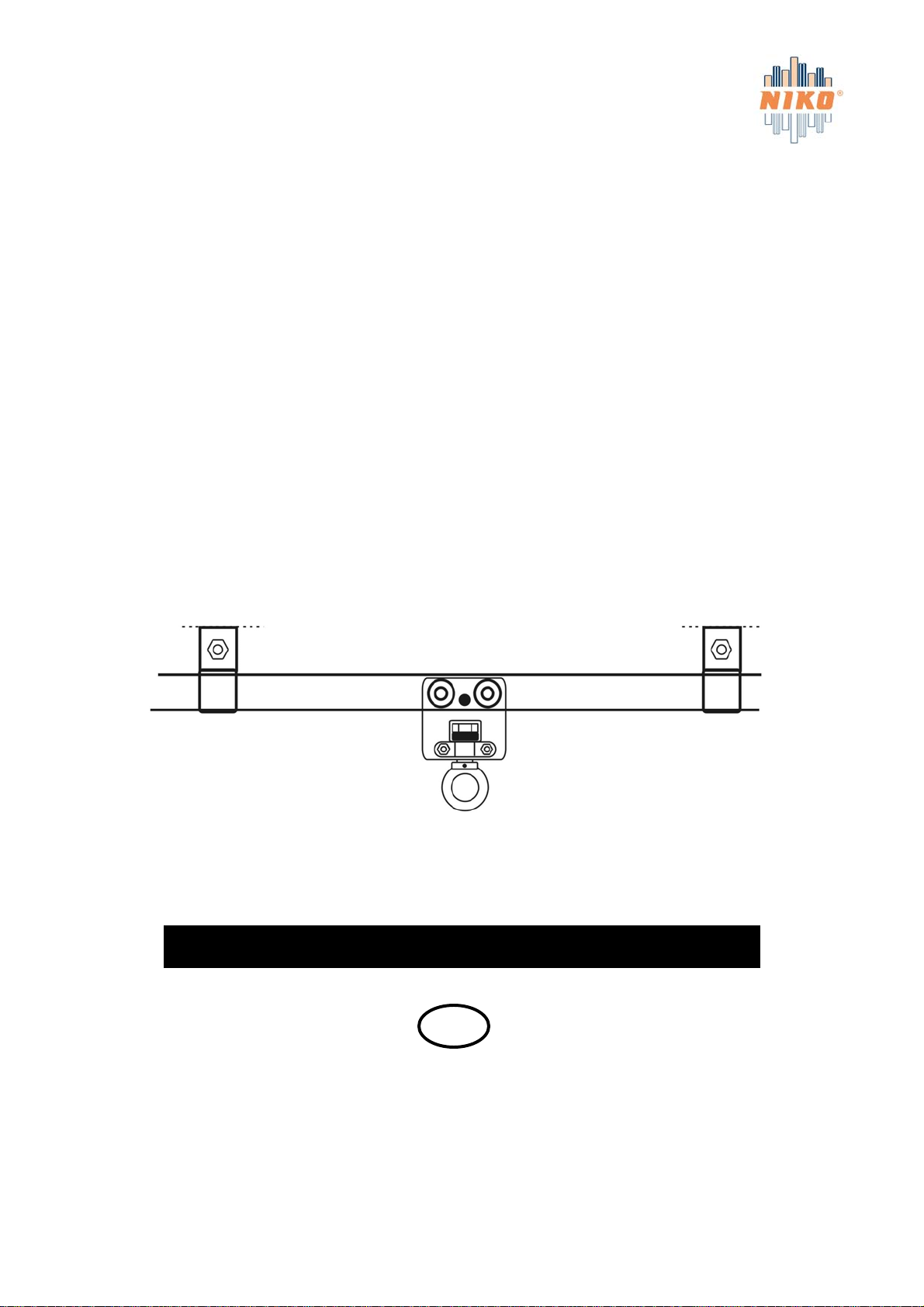
Reel Type T40 with vertical swivel vice 360° and ring nuts DIN 582.
Reel Type T20 with ball bearing oscillation and pivoted axle through an angle of max.
15°. Track stoppers of Type 25.X01 are screwed on the open end of the track.
Switch systems are delivered either with manual or automatically changing sliders.
The operation can be carried out manually or by chain pull.
3.2 Standards
The parts comply with EN 795 class D.
3.3 Construction
The track system is constructed for vertical assembly. Linear tracks or one following
a course.
Fastening: The tracks are attached to steel girders or masonry with coupling or with
angle support. The fastening distances are depicted at 4.1. It is permitted to exceed
this distance by max. 10% (through construction necessity)
Warning: Each fastening point must be capable of holding a load of 35kn.
At assembly the foundations must be checked and the holding strength of the
fastening points must be verified through protocol. At assembly onto steel
constructions- screws of DIN 933 M16 (8.8) must be used.
The free standing tracks are allowed to hang max. 300mm over the last fastening
coupling. If these distances are exceeded then additional fastening couplings are to be
built.
Page - 5 - PSS 25 - 0304
 Loading...