

NIKO L1481T-9 Datasheet
L1481T-9
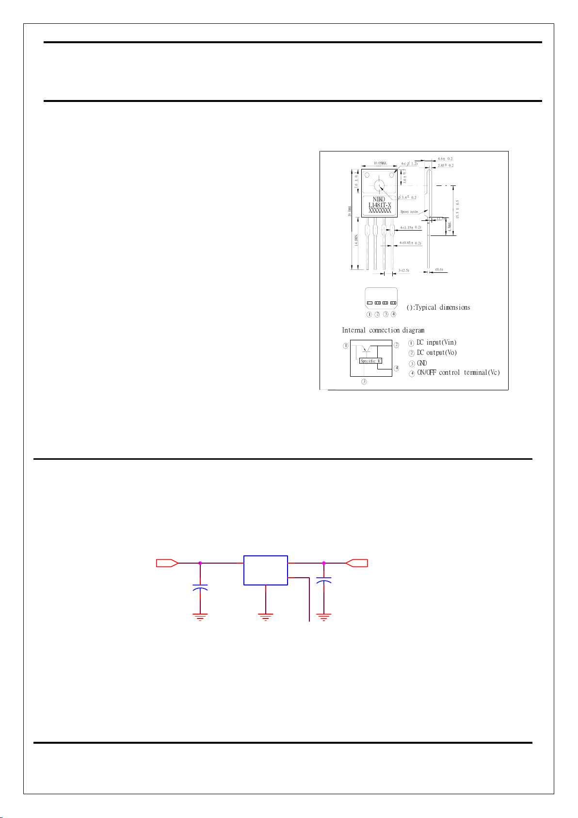
TO-220
1
Low Power-Loss
Voltage Regulators
NIKO-SEM
JUL-15-2002
FEATURES
zLow power-loss(Dropout voltage:Max.0.5
V@ IO=1A)
z Line-up for 5V and 9V output type
z Compact resin package(TO-220 package)
z High-precision output voltage type
(Output voltage precision: ±3.0%)
z Built-in ON/OFF control function
z Built-in overcurrent protection, overheat
protection, ASO protection circuit
z Lead forming type is also available.
APPLICATIONS
z Power supplies for varies electronic
equipment such as AV, OA equipment
():Typical dimensions
ON/OFF control terminal(Vc)
DC input(Vin)
DC output(Vo)
3-(2.5)
Specific IC
Internal connection diagram
3
1
1
1
4
2
GND
4
3
2
234
XXXXXXX
X
L1481T-
X
1
4
.
1
M
I
N
.
2
9
.
1
M
A
X
.
±
7
.
6
0
.
2
0.23.
4
NIK
O
4-(0.65
4-(1.15
Epoxy resin
0.2
)
±
0.2
)
±
4-(
±
0
.
2
3
.
6
10.05MAX.
1.2
)
±
(0.6)
4
.
5
M
A
X
.
(1.5)
1
5
.
5
±
0
.
5
±
0.22.85
0.24.
6
±
TYPICAL APPLICATION
L1481
U1
4
3
21
C1
100uF/25V
C2
330uF/16V
Vout
High or Open: Output O
N
Vin
ON/OFF signal
Low: Output OFF
- Basic Adjustable Regulator Circuit -
L1481T-9
TO-220
2
Low Power-Loss
Voltage Regulators
NIKO-SEM
JUL-15-2002
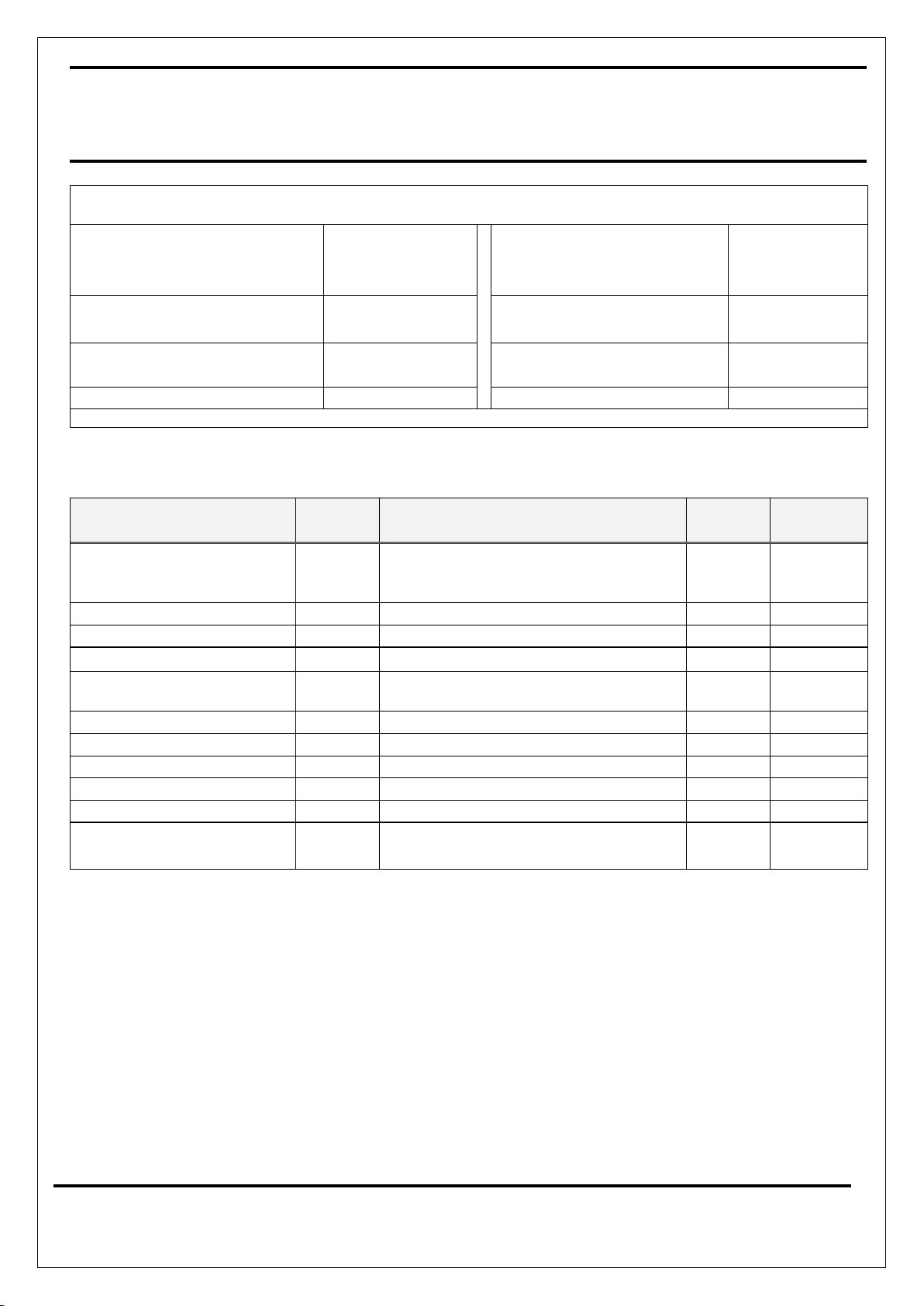
ABSOLUTE MAXIMUM RATINGS
z Input Supply Voltage, V
IN
(1)
z On/Off Control Terminal
Voltage, V
CTRL
(1)
20V
20V
z Operating Ambient
Temperature Range
-20 to 80 °C
z Power Dissipation
1.4W(No Heat Sink)
15W(Infinite heat sink)
z Storage Temperature
Range
-40 to 150 °C
z Junction Temperature
(2)
150°C
z Lead Temperature
(Soldering, 10 Seconds)
260 °C
zOutput Current 1A
(1) All are open except GND and applicable terminals
(2) Overheat protection may operate at 125<=Tj<=150°C.
ELECTRICAL CHARACTERISTICS (
Unless otherwise specified, TA = 25 °C.)
Parameter Symbol Test Conditions Typical Limits
Output Voltage Vo
(3), I
OUT
= 0.5A
9
8.73V
Min
9.27V
Max
Dropout Voltage VD
(5)
0.5V
Line Regulation REG
(LINE)
(4), I
OUT
= 5mA 0.5% 2.5%
Load Regulation REG
(LOAD)
(3)
, 5mA ≤ I
OUT
≤ 1A
0.1% 2.0%
Temperature coefficient of
output voltage
TCVO Tj=0 to 125°C, Io=5mA
±0.02%/°C
ON-state voltage for control
V
C(ON)
(3)
2.0V min
ON-state voltage for control
I
C(ON)
V
CTRL
=2.7V,(3) 20uA Max
OFF-state voltage for control
V
C(OFF)
(3)
0.8V Max
OFF-state voltage for control
I
C(OFF)
V
CTRL
=0.4V,(3)
-0.4mA Max
Quiescent Current IQ Io=0A,(3)
10mA Max
Ripple Rejection Ratio
RA
Refer to Fig.2 Test Circuit of Ripple
Rejection
55dB 45dB (Min)
(3) L1481T-9:Vin=11V
(4) L1481T-9:Vin=10~16V
(5) Input voltage shall be the value when output voltage is 95% in comparison with the initial value.
(6) In case of opening control terminal, output voltage turns on.
 Loading...