

Niko 550-00001, Home Control Installation Manual

Installation Manual
Niko Home Control

Niko Home Control: Table of contents
1
Niko Home Control: Table of contents
Warnings regarding installation............................................................................................................................2
Guarantee provisions ..........................................................................................................................................3
CE .....................................................................................................................................................................4
Key of symbols...................................................................................................................................................5
1. Installation preparations .....................................................................................................................................6
2. Controller ..........................................................................................................................................................8
3. Power supply ..................................................................................................................................................13
4. Rail coupler .....................................................................................................................................................19
5. Wall-mounted printed circuit boards and push buttons .......................................................................................21
6. Push buttons with display .................................................................................................................................31
7. Switching modules ..........................................................................................................................................48
8. Universal dimming module ...............................................................................................................................53
9. Electricity measuring modules ..........................................................................................................................59
10. Pulse counter ..................................................................................................................................................71
11. IP interface .....................................................................................................................................................75
12. Gateway .........................................................................................................................................................78
13. Touchscreen ....................................................................................................................................................81
14. Indoor motion detector .....................................................................................................................................92
15. Outdoor motion detector ..................................................................................................................................96
16. Ventilation module .........................................................................................................................................103
17. Heating or cooling module ..............................................................................................................................107
18. Motor module ................................................................................................................................................113
19. Analogue sensor module ................................................................................................................................117
20. Digital potential-free sensor module ................................................................................................................120
21. Analogue control module 0-10 V ....................................................................................................................123
22. Analogue control module 1-10 V ....................................................................................................................126
23. Push-button interface ....................................................................................................................................129
24. Nikobus interface ..........................................................................................................................................131
25. RF interface Easywave ...................................................................................................................................135

2
Warnings regarding installation
Warnings regarding installation
• The installation should be carried out by a registered installer and in compliance with the statutory regulations.
• This user manual should be presented to the user. It should be included in the electrical installation file, and it
should be passed on to any new owners. Additional copies are available on the Niko website or via the Niko support
service.
• During installation, the following should be taken into account (non-exhaustive list):
• the statutory laws, standards and regulations.
• the technology currently available at the time of installation.
• this user manual, which only states general regulations and should therefore be read within the scope of each
specific installation.
• the rules of proper workmanship.
• In case of doubt or for the specific exchange procedure in case of a possible defect, contact the Niko support
service (Belgium: +32 3 778 90 80 – United Kingdom: +44 1525 877 707) or your wholesaler/installer. Contact
details and more information can be found at
www.niko.eu under the “Help and advice” section.

Guarantee provisions
3
Guarantee provisions
• The period of guarantee is four years from the date of delivery. The delivery date is the invoice date of purchase of
the product by the consumer. If there is no invoice, the date of production applies.
• The consumer is obliged to inform Niko in writing about the non-conformity, within two months after stating the
defect.
• In case of a non-conformity, the consumer only has the right to a product repair or replacement free of charge,
which shall be decided by Niko.
• Niko shall not be held liable for a defect or damage resulting from incorrect installation, improper or careless use,
incorrect operation, transformation of the product, maintenance that does not adhere to the maintenance
instructions or an external cause, such as damage due to moisture or overvoltage.
• The compulsory regulations of the national legislation concerning the sale of consumer goods and the protection of
the consumer in the countries where Niko sells, directly or via sister companies, subsidiaries, chain stores,
distributors, agents or permanent sales representatives, take priority over the above-mentioned rules and
regulations.
• Certain Niko Home Control products and software are subject to licence terms and copyright provisions of third
parties, which you are deemed to accept and which can be found at
www.niko.eu.

4
CE
CE
This product complies with all of the relevant European guidelines and regulations. If applicable, you can find the EC
declaration of conformity regarding this product at
www.niko.eu.

Key of symbols
5
Key of symbols
L line
N neutral
t
a
rated ambient temperature; maximum temperature at which the product may be operated continuously
under normal conditions of use
μ microgap switch; switches of microgap construction have a distance between contacts in the open position
less than 1.2 mm
ˢ
without contact gap (semiconductor switch)
cos ˳ power factor
6
1. Installation preparations
1. Installation preparations
Follow the guidelines below when installing Niko Home Control.
Bus cable guidelines
• Use a bus cable with at least two wires. Choose two wires (two colours) and use these throughout the entire
installation. The bus cabling used for connecting the control elements is non-polarised.
• The copper diameter of each wire should be between 0.5 to 1 mm.
The cross-sectional area of the copper wire selected will determine the maximum permitted cable length between
the master power supply and the furthest control element in the installation.
• The bus cable to the control points has a free topology, which means that bus cables can be laid out in a star or in
a bus topology, or in a combination of both. The rule of thumb is that at least two bus cable wires must be used
between the electrical cabinet and the control points per power supply module. Do not loop cables.
• The total length of the bus cable used in a single installation should not exceed 1000 m.
Control point guidelines
• Push buttons with or without status LED:
• to be installed at 90 to 110 cm above floor level.
• to be mounted onto a single or multiple wall-mounted printed circuit board (one flush-mounting box will suffice
for a multiple wall-mounted printed circuit board).
• to be connected to a two-wire bus cable.
• Push buttons with display (eco-display, thermostat, mood setting display):
• to be installed at 120 to 150 cm above floor level.
• to be mounted onto a standard single flush-mounting box.
• to be connected to a two-wire bus cable.
A maximum of 20 push buttons with display, including a maximum of 12 thermostats, can be used per installation.
• Indoor motion detectors:
• to be installed at 90 to 110 cm above floor level.
• to be mounted onto a standard single flush-mounting box.
• to be connected to a two-wire bus cable.
Copper diameter Cross-sectional area of the copper Maximum permitted cable
length to the master
0,5 mm 0,20 mm² (e.g. UTP, FTP, STP, at least AWG24) 100 m
0,6 mm 0,25 mm² (e.g. TPVF) 150 m
0,8 mm 0,50 mm² (e.g. SVV, JYSTY) 250 m

1. Installation preparations
7
• Touchscreens:
• to be installed at eye level.
• to be mounted onto a standard single flush-mounting box.
• to be connected to an IP cable (twisted pair) and to a 26 Vdc power supply cable.
A total of ten touchscreens, smartphone or PC applications can be used per installation. See
IP interface
on page 75.
Electrical cabinet set-up regulations
• The standard Niko Home Control installation includes one power supply module and one controller. Other modules
are available separately.
• The internal layout of the electrical cabinet uses a left to right assembly system. First install the power supply
module, followed by the controller. Then mount any other Niko Home Control modules onto the DIN rail and interlink
them using a sliding contact.
• A maximum of 12 Niko Home Control modules can be interconnected per DIN rail.
• A rail coupler, or a second power supply if needed, should be used first on every new DIN rail. Connect all four
connection terminals (+, –, B1, B2) to the corresponding connection terminals of the rail coupler or the power
supply on the previous and next rails.
• A maximum of three power supply modules can be used per installation. To determine the number of power supply
modules required for your installation, follow the calculation instructions under
Power supply on page 13.
• A maximum of 20 DIN rails can be used per installation.
• One installation may include several electrical cabinets. Connect the electrical cabinets in the same way as the rail
couplers or power supply modules inside the cabinet, i.e. using four wires. If the cable length between the
electrical cabinets exceeds 20 m, you use a new power supply for the second cabinet.
• A second controller may be used to operate as a back-up and to take over should the first controller become faulty.
• Make sure that low-voltage signal cables, such as the bus cable, the IP cable and any cables connected to SELV
components are kept separate from 230V cables to avoid crosstalk and signal disruptions.
Programming guidelines
• Program the installation via computer.
The software is compatible with PC and Mac.
• The installation can be temporarily programmed manually during the testing phase. Manual programming options
are limited and will be overwritten as soon as you program the installation via computer.
8
2. Controller
2. Controller
Description
The controller operates the Niko Home Control installation based on the pre-programmed settings stored in the system.
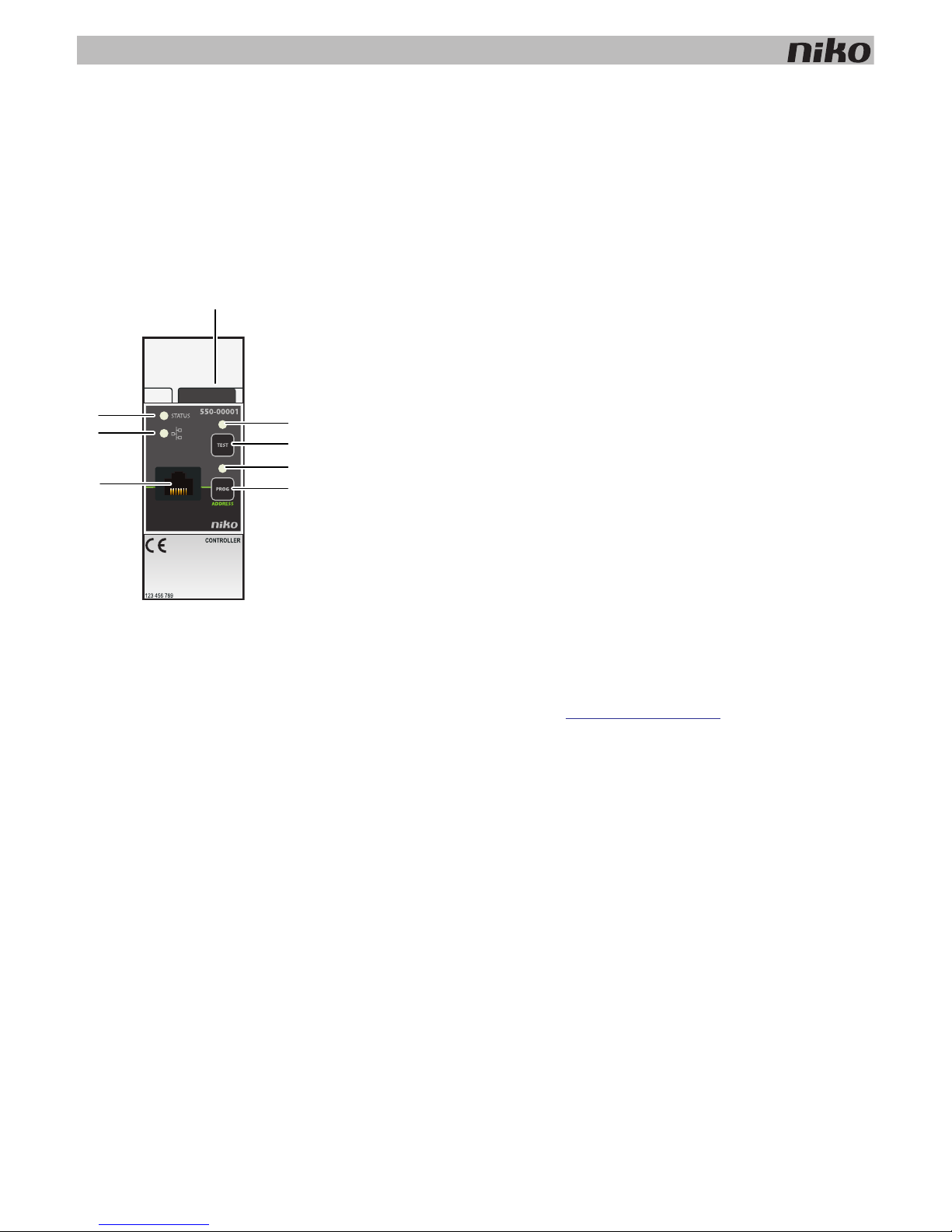
Overview
550-00001
A. Sliding contact The sliding contact is used for connecting the next
module, which means that the bus and the power supply
module are then also interconnected.
B. TEST LED The TEST LED lights up when the controller is in TEST
mode.
C. TEST button Press this button to activate TEST mode on the controller.
D. PROG LED The PROG LED lights up when the controller is in manual
PROGRAM mode.
E. PROG button Press this button to activate or deactivate manual
PROGRAM mode on the controller.
F. RJ45 port Connect your computer to this port to program the
installation.
G. ETHERNET LED The ETHERNET LED lights up during Ethernet
communication via the TCP/IP protocol.
H. STATUS LED The STATUS LED lights up in TEST mode when the
module is connected correctly and is functioning properly.
If an error occurs, the LED will blink to indicate an error
code. See
Error codes on page 11.
A
G
H
C
F
B
D
E
2. Controller
9
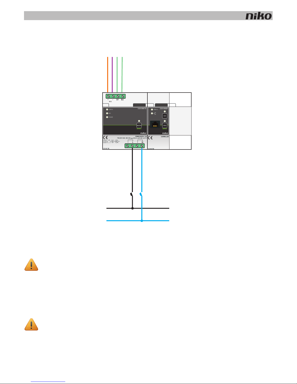
Installation
Connection diagram
Mounting instructions
One controller is required per installation. A second controller may be used to operate as a back-up.
Follow the steps below to mount the controller:
1 Press the controller onto the DIN rail until it clicks into place. Preferably position the controller right next to the
power supply module.
2 Mount the other modules onto the rail, from left to right.
When there is no room left on the rail or the maximum number of 12 modules per rail has been reached, you
simply continue on the rail above.
3 Connect the controller to the module before it. Slide the sliding contact of this module to the right until it clicks into
the controller. This will ensure that the bus and the power supply are connected.
• Ensure that the installation is disconnected from the power mains
• Mount the controller in a visible location and ensure that the RJ45 port is easily accessible.
A power supply or a rail coupler must be used at the left beginning of every DIN rail.
230V~
L
N
16A
10
2. Controller
Testing the installation
Only the POWER LED of the power supply module and the ETHERNET LED of the IP module will be lit when the Niko Home
Control installation is functioning properly. The remaining LEDs are not lit, to help save energy. If an error occurs, simply
switch the installation to TEST mode to check the status of the modules.
First press the TEST button on the controller to switch the installation to TEST mode. The STATUS LEDS indicate the status
of each module and each output.
Exit TEST mode by pressing the TEST button once more. Alternatively, the installation will automatically exit TEST mode if
no buttons are pressed during a two-minute interval.
Programming the installation manually
A number of basic functions can be temporarily programmed manually. This allows you to test the lighting options or
operate the roll-down shutters during the construction of your dwelling.
Follow the steps below to manually program the installation:
1 Connect the installation to the mains power supply.
2 Press the TEST button and verify that the STATUS LED of each module lights up.
3 Press the PROG button.
The PROG LED lights up and the controller is in manual PROGRAM mode.
4 Press the action button to which you will assign the output of your choice.
5 Press the button of the contact on the module that you wish to connect. For example, press button one or button
two on the dimming module.
6 Press the PROG button.
The PROG LED is no longer lit and the controller exits manual PROGRAM mode.
Repeat steps 3 to 6 for each function you wish to program.
This only applies to Niko Home Control action buttons. A potential-free push button connected via the push-button
interface cannot be programmed manually.
• The manually programmed outputs will be overwritten once you start programming the installation via
computer.
• As soon as the installation has been programmed via computer, you can no longer program the installation
manually.
• If you manually operate outputs via the buttons on the modules, the controller may modify your input at any
time.

2. Controller
11
Programming the installation
Program the installation after it has been completed. If the installation is expanded and additional modules are added, you
will need to reprogram the installation.
Follow the steps below to program the installation:
1 Connect the installation to the mains power supply.
2 Press the TEST button and verify that the STATUS LED of each module lights up.
3 Connect the computer to the controller via the RJ45 port.
4 Start up the programming software and select your installation project.
5 Select “Realisation” from the menu bar and follow the on-screen instructions until all the steps of the programming
process are completed.
6 Disconnect the computer from the controller.
All programmed outputs are stored in the controller. Create a back-up on your computer and provide the resident
with a copy.
Error codes
When the module is functioning properly, the STATUS LED will light up in TEST mode only. If one or several errors occur,
the LED will blink to indicate the error code of the error with the highest priority. The table below provides an overview of
all error codes.
LED ACTION ERROR POSSIBLE CAUSES
STATUS LED Blinks – one pulse per two
seconds.
Software error Wrong software version.*
*Download the latest software version
from the Niko website to upgrade the
module.
TEST LED No error codes applicable. Not applicable
PROG LED No error codes applicable.
ETHERNET LED No error codes applicable.

12
2. Controller
Technical data
• dimensions: DIN 2U
• sliding contact
• RJ45 port for communication via TCP/IP
• button for manual programming
• built-in memory chip
• CE marking
• ambient temperature: 0 - 45°C
• product in accordance with over-voltage category III and pollution degree II
3. Power supply
13
3. Power supply
Description
The power supply module provides an input voltage of 26 Vdc to the bus, the modules and the controls of the installation.
Several power supply modules can be connected in parallel in one single installation.
Overview
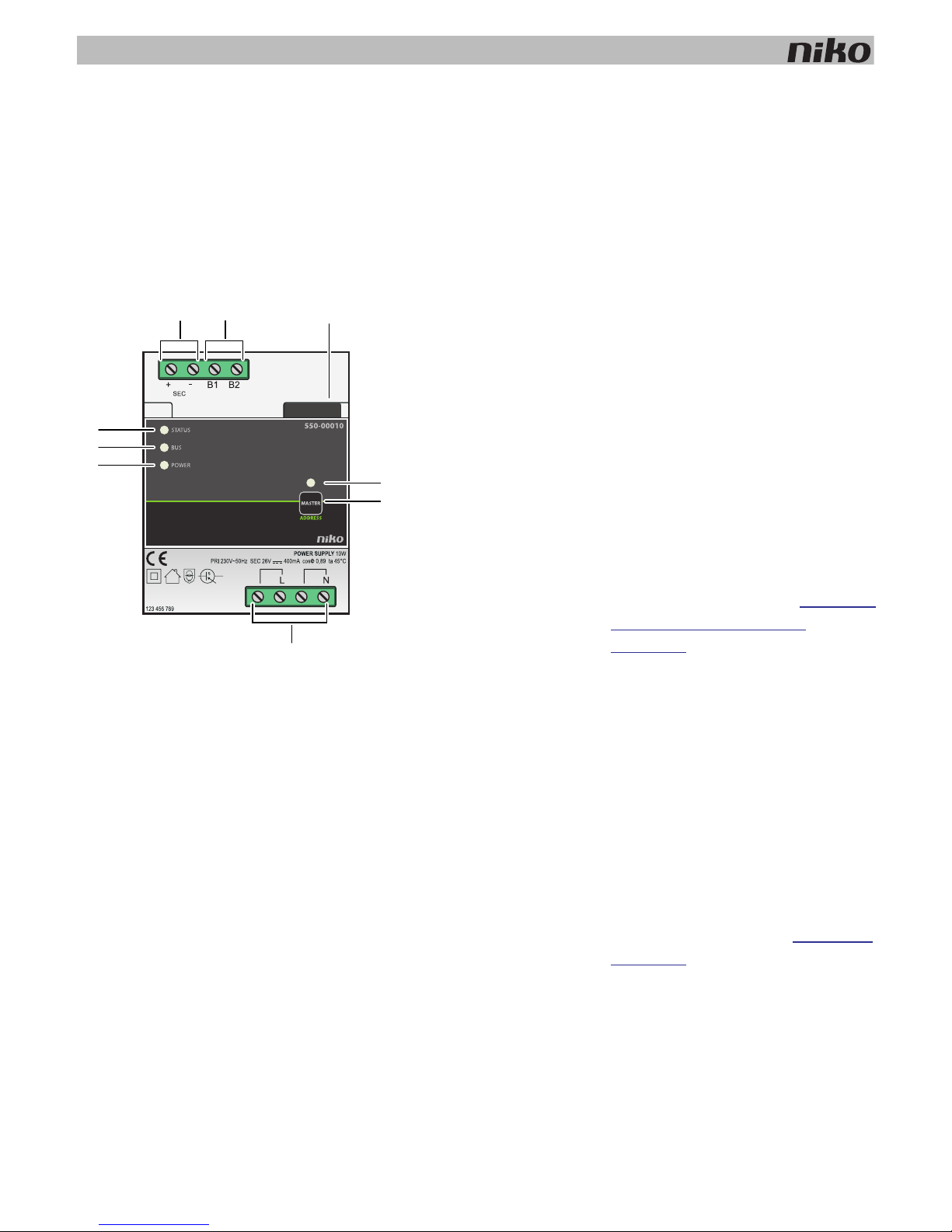
550-00010
A. +/- screw terminals The power supply provides secondary
extra low voltage via these terminals.
B. B1/B2 screw terminals This is where the bus is connected.
C. Sliding contact The sliding contact is used for
connecting the next module, which
means that the bus and the power
supply module are then also
interconnected.
D. MASTER LED The MASTER LED lights up in TEST
mode on the master power supply.
E. MASTER address button If the installation includes more than one
power supply module, you can manually
select a master module. See
Selecting a
master power supply module
on page 17.
F. L/N screw terminals This is where the 230 V mains voltage is
connected.
G. POWER LED The POWER LED lights up when the
power supply is connected to the mains
voltage.
H. BUS LED The BUS LED lights up when the bus is
communicating information.
I. STATUS LED The STATUS LED lights up in TEST
mode when the module is connected
correctly and is functioning properly. If
an error occurs, the LED will blink to
indicate an error code. See
Error codes
on page 18.
A
B C
E
F
G
H
I
D
14
3. Power supply
Sizing
Rule of thumb
The following rule of thumb can be applied to calculate the number of power supplies required: a maximum of 24 modules
inside the electrical cabinet and a maximum of 70 controls (of which 20 with status LED) per power supply. Depending on
the size and layout of your installation, you will need to install one, two or three power supplies.
This rule of thumb leaves a considerable margin for error.
Exact calculation
Each control and module consumes a specific amount of energy. This consumption is expressed in points. One power
supply is needed for every 800 points. Add the points of all the controls and modules of your installation and divide this
sum by 800 to determine the number of power supplies required. A maximum of three power supplies can be used per
installation.
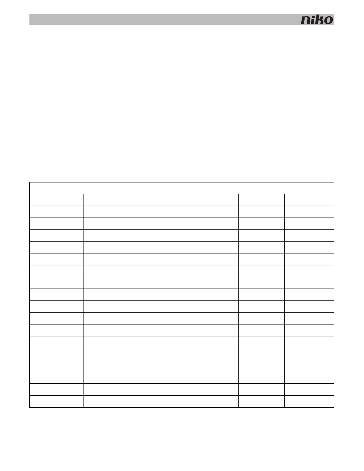
Calculate the exact number of power supplies required based on the table below.
Modules
Ref. Name Points Width
550-00001 Controller 60 2U
550-00508 IP interface 70 2U
550-00106 Switching module (6x) 5 4U
550-00103 Switching module (3x) 5 2U
550-00130 Motor module 5 4U
550-00340 Universal dimming module (2 x 400 W) 5 4U
550-00140 Ventilation module 5 2U
550-00150 Heating or cooling module 5 4U
550-00801 Electricity measuring module (1 channel) 20 2U
550-00803 Electricity measuring module (3 channels) 20 4U
550-00230 Analogue sensor module 10 2U
550-00210 Digital potential-free sensor module 10 2U
550-00240 Analogue control module 0-10 V 20 2U
550-00241 Analogue control module 1-10 V 20 4U
550-00250 Pulse counter 10 2U
550-00505 Nikobus interface 10 2U
550-00610 RF interface Easywave 20 2U
3. Power supply
15
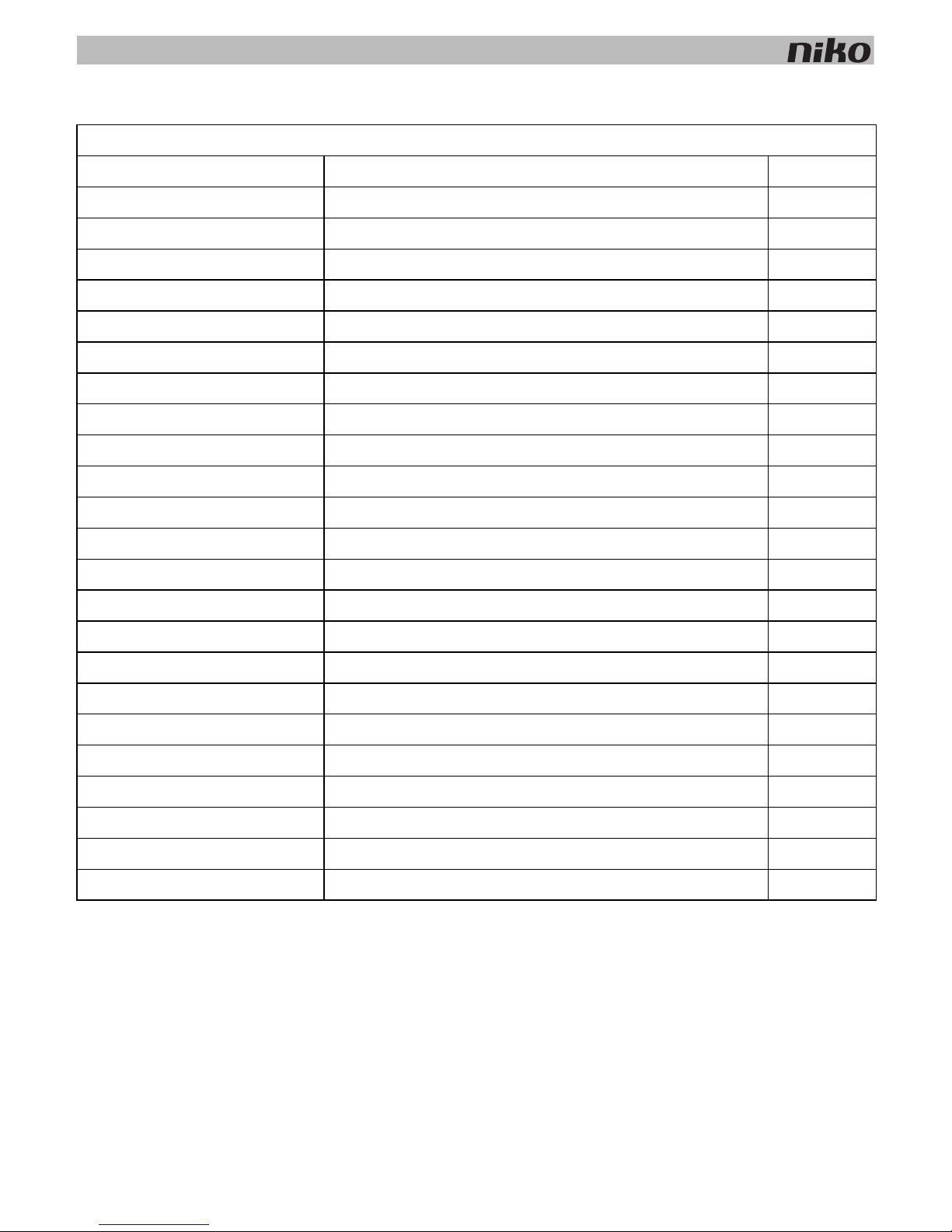
Controls
Ref. Name Points
550-2021x + 1xx-55511 Indoor motion detector 10
550-20200 Outdoor motion detector 10
1xx-51001 Single push button 3
1xx-52001 Single push button with LED 4
1xx-51002 Double push button 3
1xx-52002 Double push button with LED 5
1xx-51004 4-fold push button 3
1xx-52004 4-fold push button with LED 5
1xx-51006 6-fold push button 3
1xx-52006 6-fold push button with LED 5
550-20000 Push button interface 3
1xx-51033 Single motor control 3
1xx-52033 Single motor control with LED 5
1xx-51036 Double motor control 3
1xx-52036 Double motor control with LED 5
1xx-51043 Single dimming control 3
1xx-52043 Single dimming control with LED 5
1xx-51046 Double dimming control 3
1xx-52046 Double dimming control with LED 5
1xx-52054 Ventilation control with LED 5
550-1305x Thermostat 14
550-1304x Mood setting control 14
550-1308x Eco-display 14
16
3. Power supply
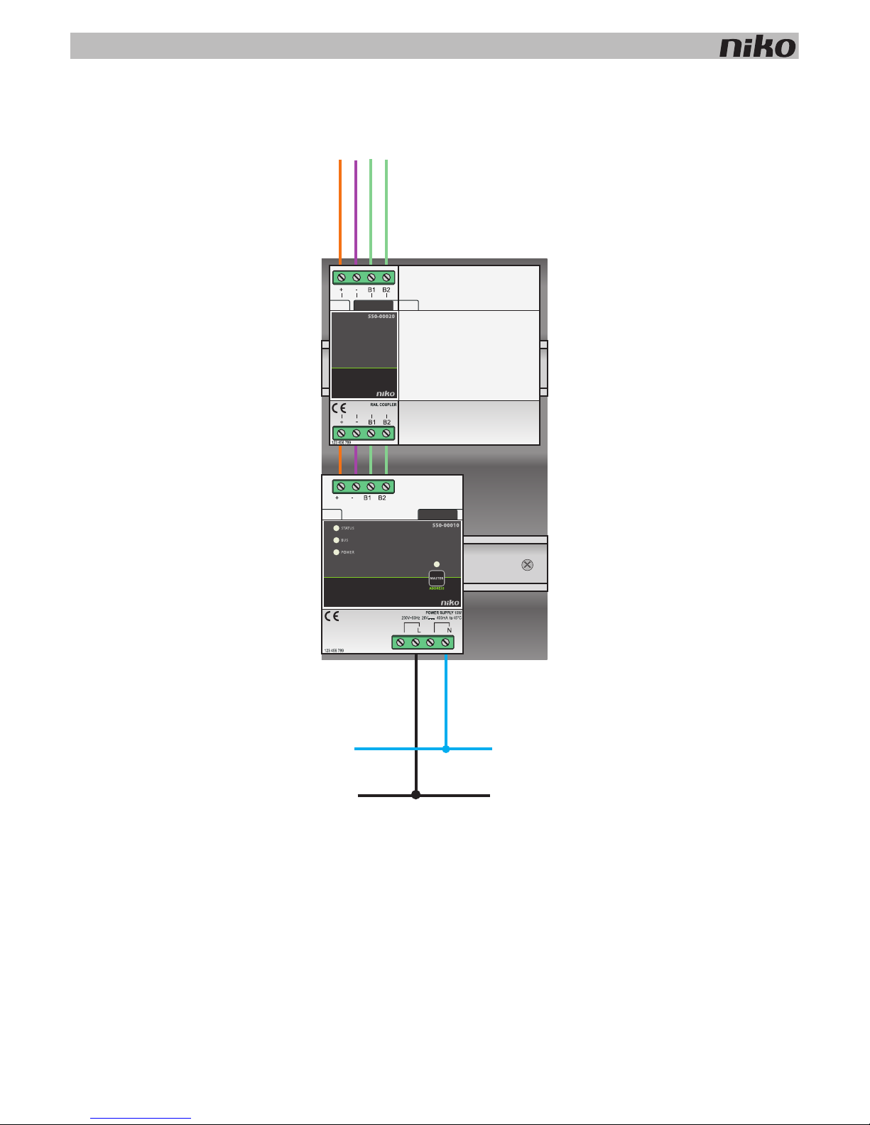
Installation
Connection diagram
N
L
230V~
3. Power supply
17
Each power supply has a capacity of 10 W. Determine the exact number of power supplies required prior to commencing
the installation process. See
Sizing on page 14.
Follow the steps below to connect and mount a power supply module:
1 Mount the power supply module onto a DIN rail in the bottom left of the electrical cabinet.
2 Mount the other modules onto the rail, from left to right. Start with the controller.
When there is no room left on the rail or the maximum number of 12 modules per rail has been reached, you
simply continue on the rail above.
3 Connect all four connection terminals (+, –, B1, B2) to the corresponding connection terminals of the rail coupler
or the power supply on the previous and next rails.
4 Each module is fitted with a sliding contact. Slide the sliding contact to the right until it clicks into the next module.
This will ensure that the bus and the power supply are connected.
5 Connect the L phase wire and the N neutral conductor to the L and N screw terminals respectively.
Selecting a master power supply module
When several power supply modules are used in a single electrical installation, you can manually select one of these
modules to act as the master power supply. The remaining power supply modules will then act as slaves. One of the
power supply modules will automatically be selected as the master if no manual selection is made.
The power supply supplies voltage to the bus, the modules and the controls. The slaves supply voltage to the modules but
not to the bus. The maximum permitted cable length between the master power supply and the control points must be
observed. See
Installation preparations on page 6. Should the master power supply module become defective, then one of
the slaves will automatically be selected as the new master. This may cause certain functions to become inoperable.
Follow the steps below to manually select a master power supply module:
1 Connect the installation to the mains power supply.
2 Locate the MASTER address button on the module that you wish to select as the master power supply module and
press and hold for two seconds.
• Observe the guidelines with regard to the layout of the electrical cabinet while mounting and connecting the
power supply. See
Installation preparations on page 6.
• Ensure that the installation is disconnected from the mains while mounting and connecting the power
supply.
A power supply or a rail coupler must be used at the left beginning of every DIN rail.
Several power supply modules may have been used across more than one electrical cabinet. Select the module
with the most central location as the master power supply module.
These settings will be stored and will remain unaffected when the installation is disconnected from the mains.
18
3. Power supply
Error codes
When the module is functioning properly, the STATUS LED will light up in TEST mode only. If one or several errors occur,
the LED will blink to indicate the error code of the error with the highest priority. The table below provides an overview of
all error codes.
Technical data
• available power: 10 W
• input voltage: 230 Vac ± 10%
• output: 26 Vdc, 400 mA (SELV; safety extra-low voltage) - 10 W
• dimensions: DIN 4U
• sliding contact
• 4 connection terminals
• CE marking
• ambient temperature: 0 - 45°C
• short circuit, over-voltage, faulty connection and overheating protection
Press the TEST button on the controller to activate TEST mode.
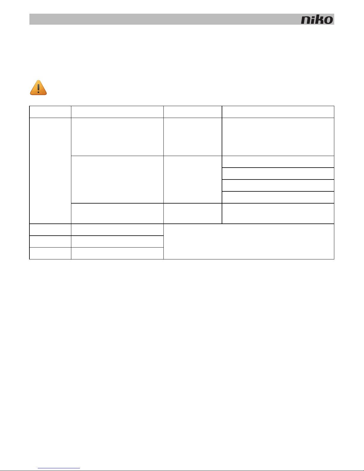
LED ACTION ERROR POSSIBLE CAUSES
STATUS LED Blinks – one pulse per two
seconds.
Software error Wrong software version.*
*Download the latest software version
from the Niko website to upgrade the
module.
Blinks – two pulses per two
seconds.
Overload or short
circuit
The bus is connected incorrectly.
The bus voltage is too low.
Bus overload. Check all points.
One of the bus members is defect.
Blinks – three pulses per two
seconds.
Overheating The temperature inside the electrical
cabinet is too high.
MASTER LED No error codes applicable. Not applicable
BUS LED No error codes applicable.
POWER LED No error codes applicable.
4. Rail coupler
19
4. Rail coupler
Description
The rail coupler interconnects the power supply voltage and the bus of the rail below to the modules via the sliding
contact.
Overview
Installation
Follow the steps below to install the rail coupler:
1 Click the rail coupler onto the left beginning of the DIN rail.
2 Connect all four connection terminals (+, –, B1, B2) to the corresponding connection terminals of the rail coupler
or the power supply on the previous and next rails.
3 Each module is fitted with a sliding contact. Slide the sliding contact to the right until it clicks into the next module.
This will ensure that the bus and the power supply are connected.
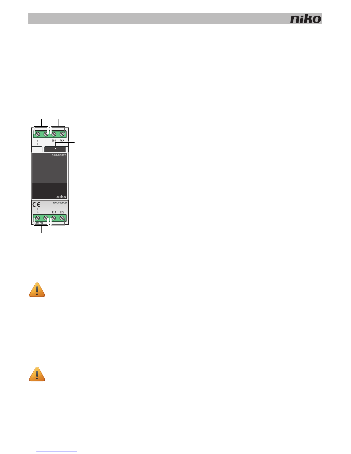
550-00020
A. +/- screw terminals
B. B1/B2 screw terminals
C. Sliding contact
A power supply or a rail coupler must be used at the left beginning of every DIN rail.
• Bus cables can be used between terminals B1/B2 of any rail coupler and a control point.
• A rail coupler can be interconnected to another rail coupler located in a different electrical cabinet. The
cable length between both rail couplers should not exceed 20 m. If the distance between the electrical
cabinets exceeds 20 m, you use a new power supply for the second cabinet.
A
B
A
B
B
C

20
4. Rail coupler
Technical data
• dimensions: DIN 2U
• sliding contact
• 2 x 4 connection terminals
• connection terminals for 3 x 1,5 mm² or 2 x 2,5 mm² or 1 x 4 mm²
• CE marking
• ambient temperature: 0 - 45°C

5. Wall-mounted printed circuit boards and push buttons
21
5. Wall-mounted printed circuit boards and push buttons
5.1. Wall-mounted printed circuit boards
Description
A wall-mounted printed circuit board includes all the electrical and mechanical components required to connect one or
several push buttons to the Niko Home Control installation. Niko offers horizontal, vertical, single or multiple printed circuit
boards. Choose the type of printed circuit board depending on the number of action buttons required and on a horizontal
or vertical assembly. The printed circuit board can be easily replaced by a larger one at a later stage if the need arises to
expand the installation.
Reference codes
550-14020: double wall-mounted printed circuit board (centre distance 71 mm, horizontal)
550-14021: double wall-mounted printed circuit board (centre distance 60 mm, vertical)
550-14027: double wall-mounted printed circuit board (centre distance 71 mm, vertical)
550-14030: 3-fold wall-mounted printed circuit board (centre distance 71 mm, horizontal)
550-14031: 3-fold wall-mounted printed circuit board (centre distance 60 mm, vertical)
550-14037: 3-fold wall-mounted printed circuit board (centre distance 71 mm, vertical)
550-14040: 4-fold wall-mounted printed circuit board (centre distance 71 mm, horizontal)
550-14090: connection unit for multiple wall-mounted printed circuit board
550-14110: single wall-mounted printed circuit board with connector
550-14115: single wall-mounted printed circuit board with bridge
450-00067: set of claws for wall-mounted printed circuit board
450-00068: set of claws for connection unit
22
5. Wall-mounted printed circuit boards and push buttons
Installation
Connecting single wall-mounted printed circuit boards
The double plug-in connector is used for connecting the bus cable to the wall-mounted printed circuit board and for
establishing a connection to the next control element. It has two contacts with two openings each.
To connect single wall-mounted printed circuit boards, you connect the bus using two wires from the bus cable. Connect
each wire separately to one of the contacts. Each contact is marked by the letter B.
The wall-mounted printed circuit board is now connected. Use the other opening of the contact to establish a connection
to the next control element if required.
Connecting multiple wall-mounted printed circuit boards
You need one connection unit for each multiple wall-mounted printed circuit board you wish to connect. Connection units
are available separately. The connection unit includes a double plug-in connector, which allows you to connect the bus
cable and establish a connection to the next control element. The connector has two contacts with two openings each.
To connect multiple wall-mounted printed circuit boards:
1 Connect two wires of the bus cable to the contacts of the connection unit.
The connection unit is now connected. Use the other opening of the contact to establish a connection to the next
control element if required.
2 Remove the transparent tape from the wall-mounted printed circuit board where the connection unit will be
mounted. This connection unit is mounted closest to the flush-mounting box.
3 Press the connection unit onto the wall-mounted printed circuit board until it clicks into place. Secure the
connection unit using two screws.
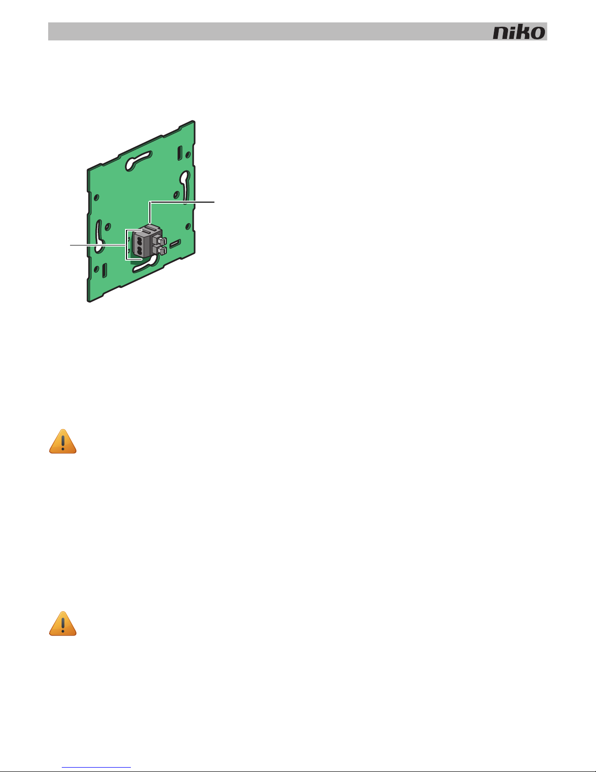
550-14110
A. Double plug-in connector
B. Two contacts with two openings each
• Strip the wires of the bus cable 9 - 10 mm.
• A maximum of two wires with a diameter of 0.5 - 1 mm each can be connected per contact.
• Strip the wires of the bus cable 9 - 10 mm.
• A maximum of two wires with a diameter of 0.5 - 1 mm each can be connected per contact.
B
A
5. Wall-mounted printed circuit boards and push buttons
23
Assembly
To mount the wall-mounted printed circuit board, press the unit onto a single flush-mounting box until it clicks into place.
Secure using screws.
Use a set of claws if no screw holes are provided in the flush-mounting box. Sets of claws for single and multiple
wall-mounted printed circuit boards are available separately.
Secure the sides of larger wall-mounted printed circuit boards onto the wall using the screw holes provided in the
wall-mounted printed circuit board.
Use a single wall-mounted printed circuit board with metal bridge on very uneven walls or in combination with other Niko
flush-mounting units with bridge The bridges can be clicked together.
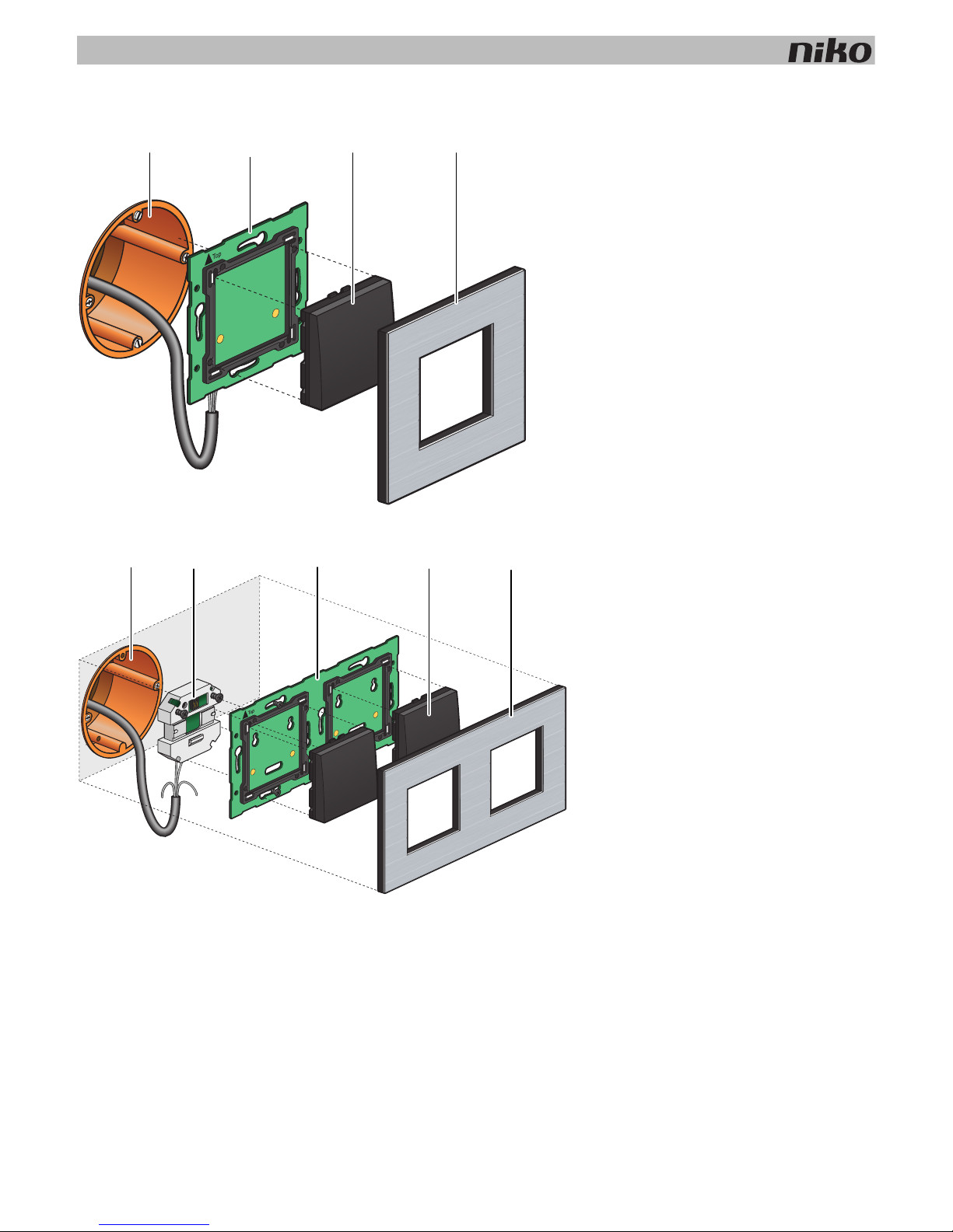
Installation diagram for single wall-mounted printed circuit boards
A. Single flush-mounting box
(not a Niko product)
B. Single wall-mounted printed circuit board
C. Push button
D. Flush surround plate
Installation diagram for multiple wall-mounted printed circuit boards
A. Single flush-mounting box
(not a Niko product)
B. Connection unit
C. Multiple wall-mounted printed circuit
board
D. Push button
E. Flush surround plate
A
B
C D
A
B C
D
E
24
5. Wall-mounted printed circuit boards and push buttons
Technical data
• wall-mounted printed circuit board material: epoxy
• material thickness: 1 mm
• one double connector
• connection unit dimensions: 51 x 43 x 22 mm (HxWxD)
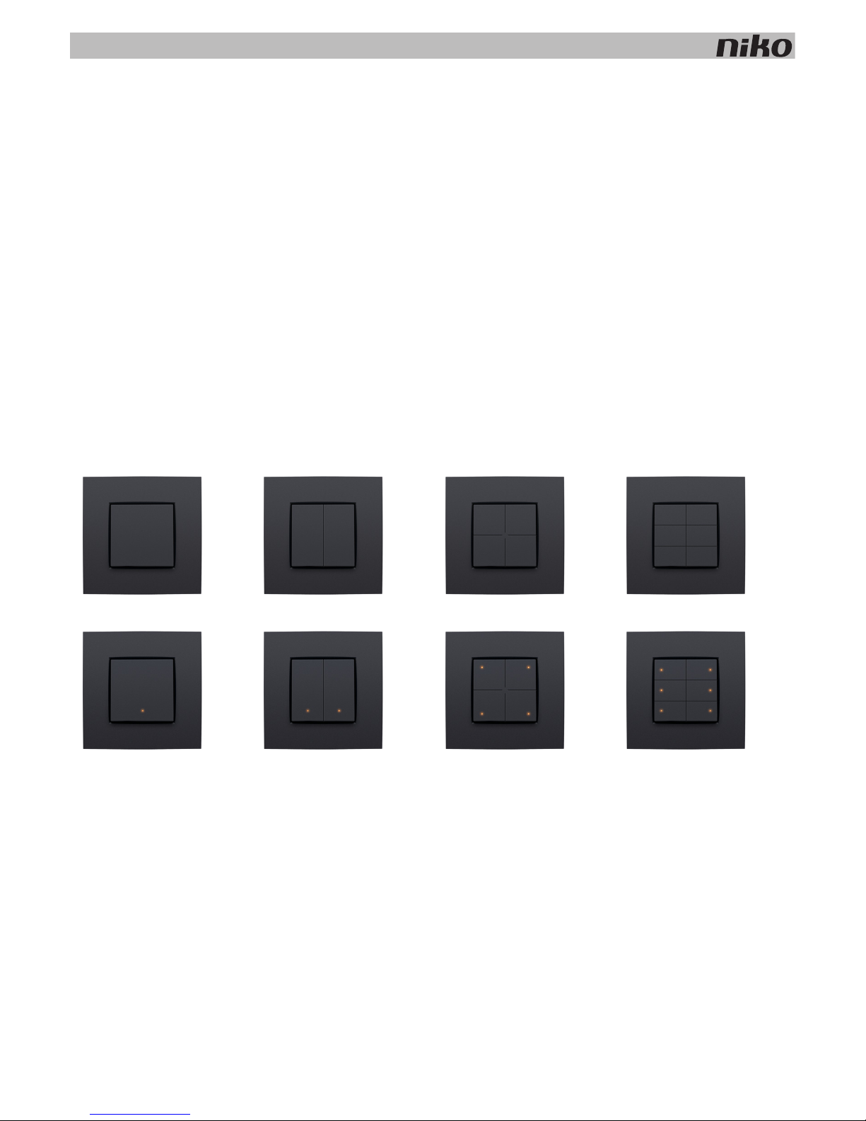
5.2. Generic push buttons
Description
Single, double, 4-fold and 6-fold push buttons are available with or without status LED. These push buttons include one or
more action buttons that allow the resident to operate the Niko Home Control functions.
Overview
Operation
Each action button can either control a light point or a light circuit, dim a dimmable light point or activate a mood setting.
A mood setting is a combination of pre-programmed output settings.
Action buttons with status LED will indicate the status of their respective output. Using the programming software, you can
program the LEDs to light up when the output is either activated or deactivated .
1xx-51001 1xx-51002 1xx-51004 1xx-51006
1xx-52001 1xx-52002 1xx-52004 1xx-52006
5. Wall-mounted printed circuit boards and push buttons
25
Installation
The control element consists of a push button and one or more action buttons. Complete the installation using the flush
surround plate of your choice from our series Niko Pure, Niko Intense or Niko Original.
To mount the push button, press the unit onto a Niko Home Control wall-mounted printed circuit board until it clicks into
place. The push button is now secure. The functions of the action buttons can be assigned while programming the
installation by linking each function to the unique address of each action button during the addressing phase. This
information is then stored in the controller.
Technical data
• resting potential: 26 Vdc (SELV, safety extra-low voltage)
• ambient temperature: 0 - 50°C
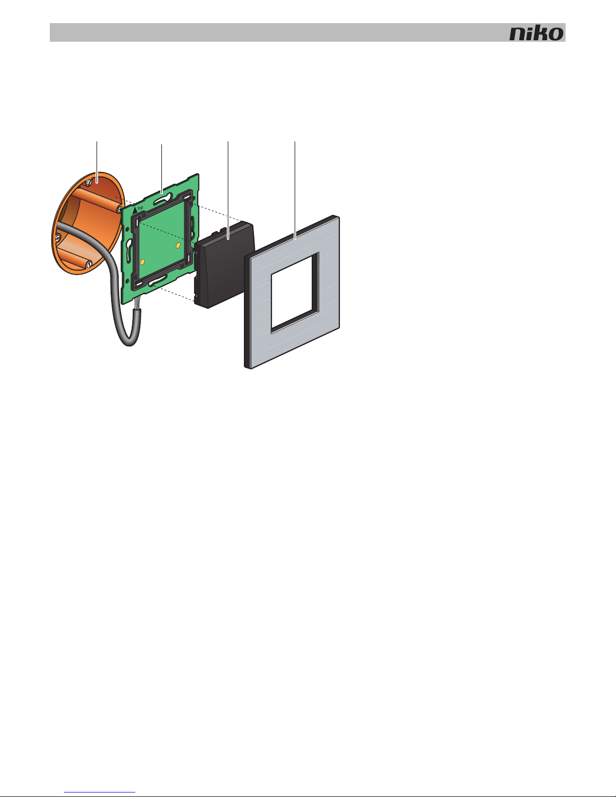
Installation diagram for single wall-mounted printed circuit boards
A. Single flush-mounting box
(not a Niko product)
B. Single wall-mounted printed circuit board
C. Push button
D. Flush surround plate
A
B
C D
26
5. Wall-mounted printed circuit boards and push buttons
5.3. Specific push buttons
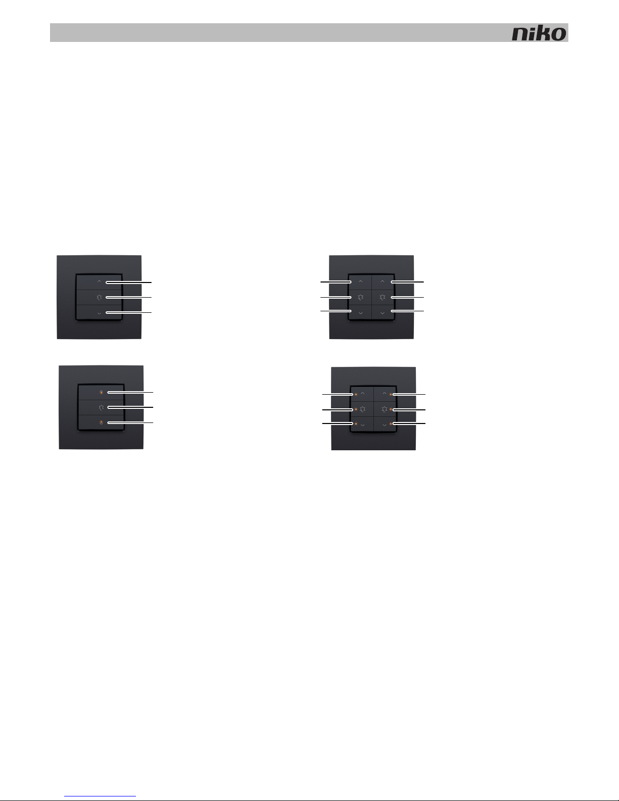
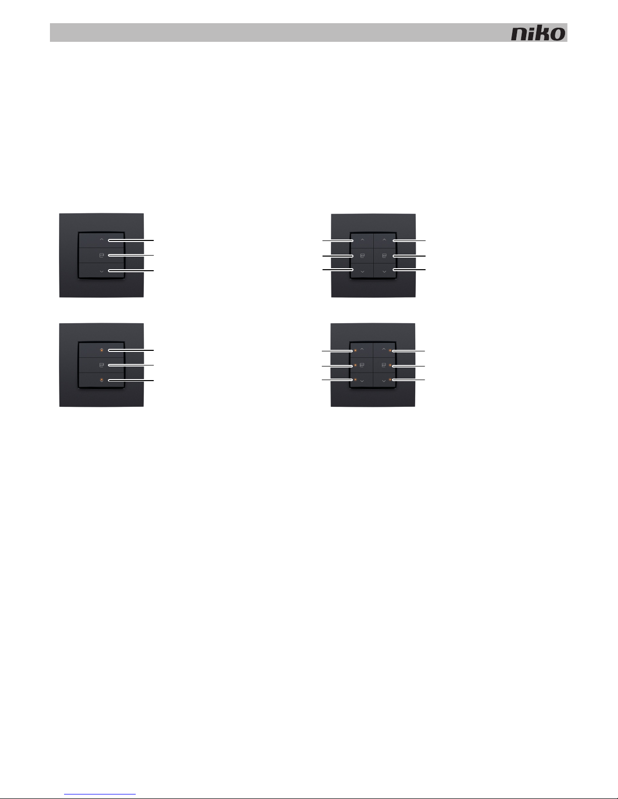
5.3.1. Push buttons for dimming
Description
Push buttons for dimming are available in a single-row (three action buttons) or double-row (six action buttons)
configuration, with or without status LED. They allow the resident to operate one or two light points respectively, or groups
of light points, via the Niko Home Control installation.
Overview
Operation
The specific action buttons on each push button are arranged in groups of three. Each group consists of the following
buttons: “A”, “B” and “C”.
Action buttons with status LED will indicate the status of their respective output. Using the programming software, you can
program the LEDs to light up when the output is either activated or deactivated.
1xx-51043
1xx-51046
1xx-52043 1xx-52046
A
B
C
AA
BB
CC
A
B
C
AA
BB
CC
5. Wall-mounted printed circuit boards and push buttons
27
The table below provides an overview of all action button functions.
‘Before’ status Action ‘After’ status
Light off Briefly press "A" (< 0.4 s) “Memory off” means the light intensity level will reach
100%.
“Memory on” means the light intensity level will return to
the previous setting,
which is the last used light intensity level prior to the
dimmer being switched off.
The “Memory off” or “Memory on” option can be selected
during the programming phase of the installation.
Light off Briefly press "B" (< 0.4 s) Preference setting (standard 50%)
Light off Briefly press "C" (< 0.4 s) The light is switched on. The light intensity level remains at
the lowest setting.
Light off Press and hold "A" (≥ 0.4 s) The light intensity level will increase until the button is
released or until the maximum level is reached.
Light off Press and hold "B" (≥ 0.4 s
and < 3 s)
Preference setting (standard 50%)
Light off Press and hold "B" (> 3 s) The current light intensity level is now saved as the new
preference setting.
Light off Press and hold "C" (≥ 0.4 s) The light is switched on. The light intensity level remains at
the lowest setting.
Light on Briefly press "A" (< 0.4 s) The light intensity level will reach 100%.
Light on Briefly press "B" (< 0.4 s) Preference setting (standard 50%)
Light on Briefly press "C" (< 0.4 s) The light is switched off.
Light on Press and hold "A" (≥ 0.4 s) The light intensity level will increase until the button is
released or until the maximum level is reached.
Light on Press and hold "B" (< 3 s) Preference setting (standard 50%)
Light on Press and hold "B" (> 3 s) The current light intensity level is now saved as the new
preference setting.
Light on Press and hold "C" (≥ 0.4 s) The light intensity level will decrease until the button is
released or until the minimum level is reached.
28
5. Wall-mounted printed circuit boards and push buttons
Installation
See Installation on page 25.
Technical data
• resting potential: 26 Vdc (SELV, safety extra-low voltage)
• ambient temperature: 0 - 50°C
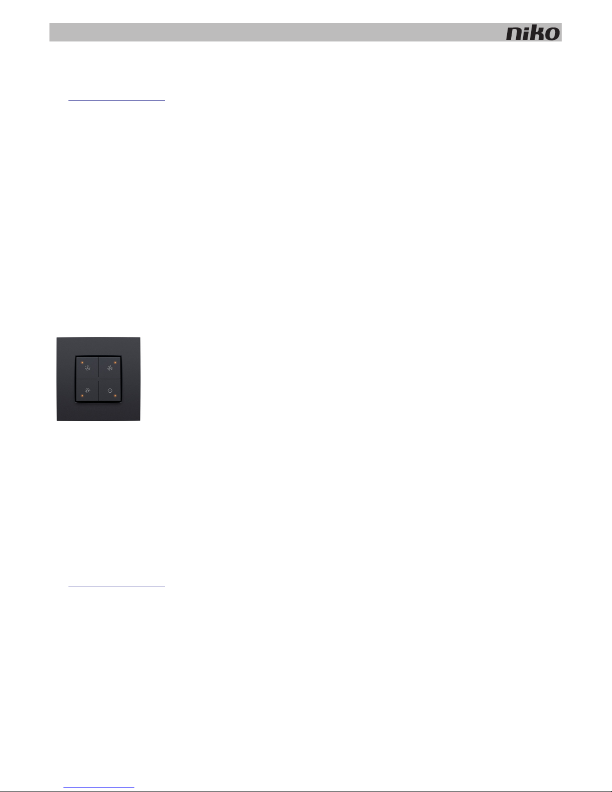
5.3.2. Push button for ventilation
Description
The push button for ventilation allows the resident to operate the central ventilation system (type C or D) via the Niko Home
Control installation.
Overview
Operation
The push button includes four action buttons: one for each setting of the central ventilation system (low, medium, high)
and one that activates the boost function. When the boost function is activated, the ventilation system will operate at the
highest setting during a preset amount of time before returning to the previous setting.
Installation
See Installation on page 25.
Technical data
• resting potential: 26 Vdc (SELV, safety extra-low voltage)
• ambient temperature: 0 - 50°C
1xx-52054
5. Wall-mounted printed circuit boards and push buttons
29
5.3.3. Push buttons for motor control
Description
Push buttons for motor control are available in a single-row (three action buttons) or double-row (six action buttons)
configuration They allow the resident to operate the motors of one or two groups of roll-down shutters, sun blinds or
venetian blinds integrated in the Niko Home Control installation.
Overview
Operation
The specific action buttons on each push button are arranged in groups of three. Each group consists of the following
buttons: "A", "B" and "C".
Action buttons with status LED will indicate the status of their respective output. Using the programming software, you can
program the LEDs to light up when the output is either activated or deactivated .
1xx-51033
1xx-51036
1xx-52033 1xx-52036
A
B
C
AA
BB
CC
A
B
C
AA
BB
CC
 Loading...