

NIHON PC60QL03N Datasheet
SBD MODULE 60A/30V PC60QL03N
PC60QL03N
PC60QL03N PC60QL03N
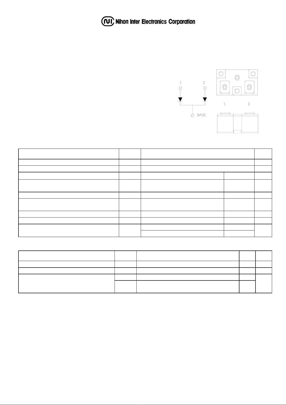
OUTLINE DRAWING
FEATURES
* Dual-Cathode Common to Base Plate
* Extremely Low Forward Voltage Drop
* Low Power Loss, High Efficiency
* High Surge Capability
* UL Recognized, File No. E187184
TYPICAL APPLICATIONS
* High Frequency Rectification
Maximum Ratings Approx Net Weight:65g
Voltage
Voltage Rating
Voltage Voltage
Repetitive Peak Reverse Voltage V
Repetitive Peak Surge Reverse Voltage
Electrical Rating
Electrical Rating
Electrical RatingElectrical Rating
Average Rectified Output Current IO
RMS Forward Current I
Surge Forward Current I
Operating JunctionTemperature Range
Storage Temperature Range
Mounting torque Ftor
Rating
RatingRating
Symbol
30 V
RRM
V
RRSM
Per Arm 94 A
F(RMS)
FSM
Tjw -40 to +125
Tstg -40 to +125
35 (Pulse Width ≤ 1 µsec, Duty ≤1/50)
50Hz Half Sine Wave
per Arm, Tc=92°C
50 Hz Half Sine Wave,1cycle
Non-repetitive, per Arm
Case mounting(recommended) 1.45
Terminal Screw(recommended) 1.45
PC60QL03N
Condition
Condition Rating
ConditionCondition
Electrical • Thermal Characteristics
Unit
V
Rating
RatingRating
60 A
800 A
°C
°C
N•m
Characteristics
Peak Forward Voltage
Peak Reverse Current
Thermal Resistance
We recommend the use of the electrical conductive grease.
In case of parallel use, consider in balance of the current of each arms.
Symbol Test Conditions Max. Unit
V
FM
I
RM
Rth(j-c) Junction to Case, per Arm 0.74
Rth(c-f)
= 60A, Tj=25°C, per Arm
I
FM
= V
V
RM
Base Plate to Heat Sink with Thermal
Compound
RRM,
Tj= 25°C, per Arm
0.50 V
80 mA
0.12
°C/W
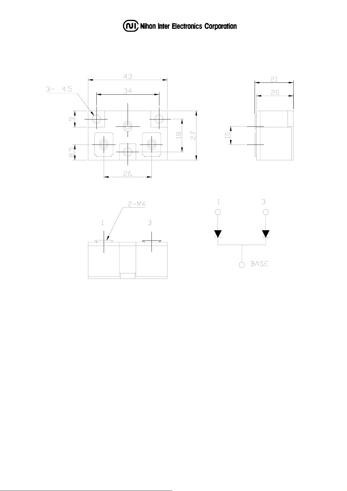
PC60QL03N OUTLINE DRAWING (Dimensions in mm)
φ
 Loading...