

Page 1
EQUIPMENT FOR MEASUREMENT&CONTROL AND DRYERS
B. Nikolica-Serjoze 12, 18000 Nis, Serbia; Phone/Fax:+38118 211-212, 217-468; [email protected]; www.nigos.rs
Automatic control unit MC-2000 (version 5.4.6) 1
USER'S MANUAL
for automatic control unit MC-2000
1. MC-2000 MAIN CHARACTERISTICS
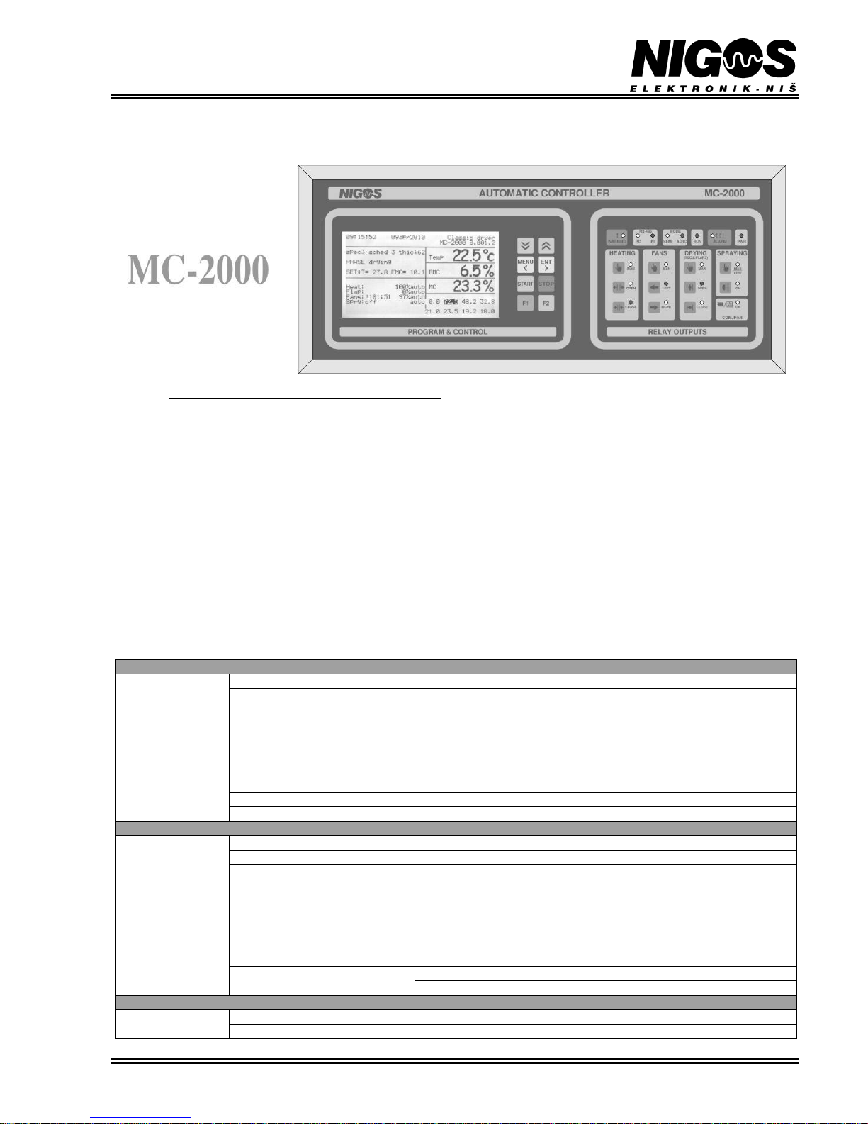
Automatic control unit MC-2000 is a device intended for drying process control in conventional (steam) and dehumidifying dryers. Controller
provides optimum conditions in the dryer through air temperature and humidity control.
Controller MC-2000 is delivered pre-connected in the power electric panel (KRO). User connects equipment in the kiln to appropriate clamps
in the power electric panel. MC-2000 receives information about air temperature and equilibrium moisture content (EMC) from 2 measuring
points and wood moisture content (MC) from 8 points from the measurement module MKM-08 via communication line. MKM-08 receives
these data from 2 measurement boxes DS-04t, transforms them and then transfers the data to MC-2000 controller. Controller controls the
drying process based on these data. It can operate in automatic or semi-automatic mode, depending on settings made by user. When in
automatic control mode, MC-2000 follows the chosen drying regime and achieves optimal drying conditions in the kiln automatically. In
semiautomatic control mode, user can set desired setpoints for air temperature and humidity, based on the personal experience, and the unit
only maintains those values inside the kiln at the desired point. The unit can be connected to a PC, which enables control of drying process
from distance (from the office or suitable operating room). Additional capability of the MC-2000 controller is manual control of the drying
process. User can use buttons, placed in the right part of MC-2000 labeled with “RELAY OUTPUTS”, for manual control of relay outputs.
When manual control is active the controller only displays the measured values. In all other cases, the MC-2000 controls relay outputs
automatically. All output adjustments are built-in, so the user has no influence on their operation during drying process. Most irregular
situations that may occur are registered and resolved within the controller's program options. User intervention is required in certain situations
that cannot be resolved by controller, or in case of unknown conditions.
MC-2000 TECHNICAL SPECIFICATION
Main characteristics
Power supply
230Vac; 50Hz; 300mA
Number of digital inputs
4
Number of analogue inputs
1 (Pt1000; T: - 25 160 0C)
Number of outputs
9
Communication lines
2
Displays
LCD with 16 rows x 40 characters
Operating conditions
T: 0 50 0C; RH: 5 90%
Storage
T: - 40 85 0C; RH: 5 90%
Dimensions (W x H x D)
(470 x 200 x 110) mm
Weight
3200g
Outputs
Relay outputs
Number of outputs
9
Characteristics
Common contact; 8A / 250 Vac, , uninterrupted load 3A max
Purpose and number of outputs
2 outputs for temperature control (heating valves))
2 outputs for fans operation and direction control
2 outputs for humidity control (servo-controlled flaps)
1 output for spraying
1 output for compressor
1 output for alarm
Optocapler outputs
Number of outputs
3
Purpose and number of outputs
2 isolated digital outputs for frequency inverter starting
1 analogue output for frequency inverter control
Communication
Digital
Communication standard
RS-485
Protocol
S - NIGOS
Page 2
EQUIPMENT FOR MEASUREMENT&CONTROL AND DRYERS
B. Nikolica-Serjoze 12, 18000 Nis, Serbia; Phone/Fax:+38118 211-212, 217-468; [email protected]; www.nigos.rs
2 Automatic control unit MC-2000 (version 5.4.6)
MKM-08 TECHNICAL SPECIFICATION
Inputs
Temperature input
Number of inputs
2
Range
-20 110 0C; 10mV / 0C
EMC input
Number of inputs
2
Range
2.0 30 % EMC
MC inputs
Number of inputs
8
Range
5 160 %
2. INSTALLATION
2.1. CONNECTING DIAGRAM
MC-2000 is a controller primarily intended for drying control in the kiln that is part of system with large number of dryers. It is very common
for these systems that control and surveillance equipment for all dryers is placed in one room. Actual dryer, which is controlled by a certain
controller placed in the operating room, can be significantly distanced from there (up to 300 m). There are 2 types of signals that are
transmitted between the controller and the equipment in the dryer. Control signals can be transmitted at that distance with no significant loss,
but data signals obtained from temperature, EMC and MC probes, can be corrupted during transport. That is why the control signals can be
transmitted from the appropriate clamps in power electric switch board directly to the kiln’s executive equipment, while data signals must be
converted at first in the form that is suitable for transmission at long distance. Converting of data signals is performed in the communication
box MKM-08 that is placed near to drying chamber (usually on the chamber' wall). Software control of system configuration is fully
supported. Optimal configuration of the system is achieved with the proper choice of the number of attached temperature probes, and probes
for Equilibrium Moisture Content (EMC) and wood moisture content (MC).
Heating (valves)
Drying (dampers)
Spraying
Recuperator/Compressor
Inverter
Flow fans air direction
MKM-08
KRO
F/UTP CAT.5E 4pairs
Alarm/Circulation pump
Analogue inputs
PC
3~
MKM-08
Digital inputs
WAR NIN G SE MIINTPC RUN PWRAU TO
MOD ERS -485
!
ALA RM
MC-2000AUTO MATIC CO NTROLLER
!! !
HEATING FANS DRYING SPRAYING
COM./FAN
MAN
OPEN
CLOSE RIG HT
LEFT
MAN MAN
(REC U./ FLAPS)
OPEN
CLOSE ON
ON
MAN
TEST
RELAY OUT PUTSPROGRAM & CONTROL
DS-04t
DS-04t
LI6YC6Y 12x0.34mm
2
Dryer
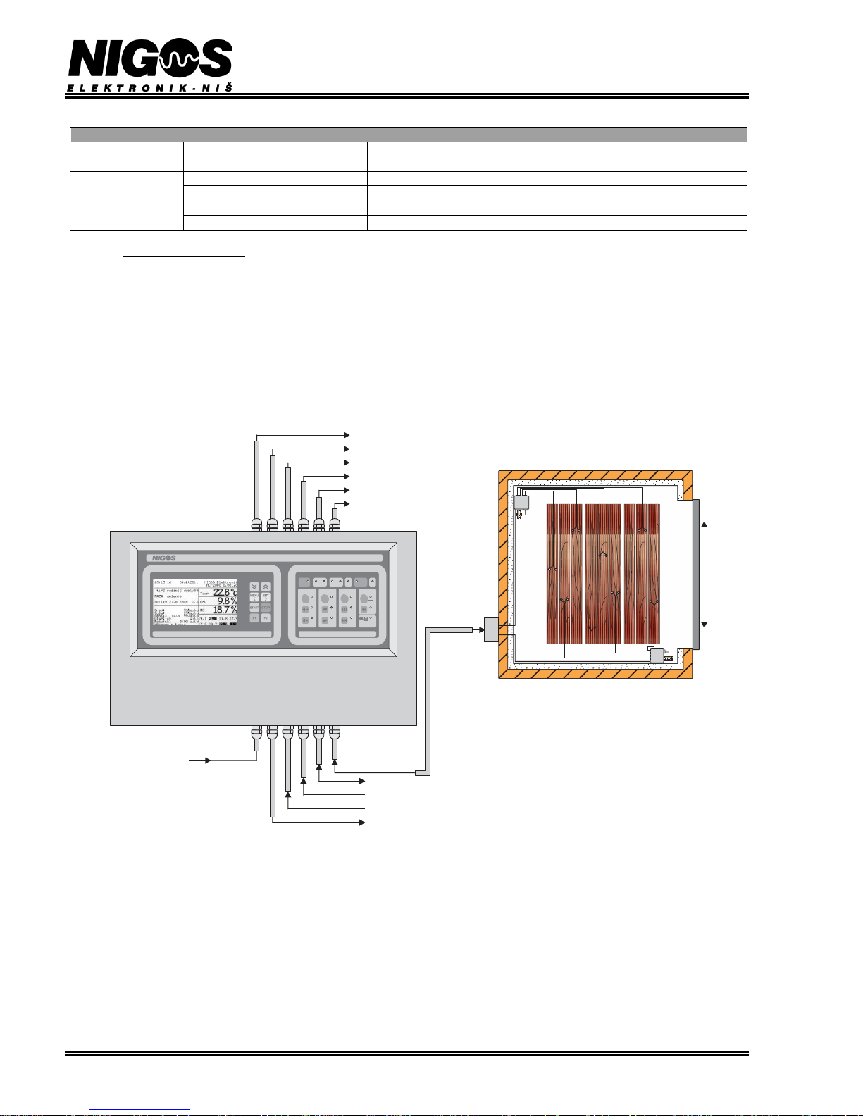
Picture 2.1. Schematic representation of MC-2000 connection in the system with
2 temperature and EMC measurement points and 8 MC measuring points
MC-2000 controller has 9 relay outputs:
- 2 of them are reserved for temperature control (opening and closing heating valve) with selectable PI or ON/OFF type of control,
- 2 for changing air flow direction (flow fans control),
- 2 for humidity control (opening and closing flaps) with selectable PI or ON/OFF type of control,
- 1 for compressor or fan in the flap,
- 1 for spraying system control, and
- 1 for alarm.
All relays outputs are connected to appropriate clamps in power electric switch board (KRO) with certain protection elements (fuse, contactor,
relay) installed between. User must just connect cables which come from equipment in the chamber to adequate clamps in the KRO.
MKM-08 box is connected to MC-2000 via communication cable. It is also possible to connect inverter (frequency controller) for fans speed
control. Inverters are connected to clamps in KRO. Each fan can be attached to separate inverter.
MC-2000 controller can be connected to a personal computer (PC). Communication standard RS-485 is used for all data transfers.
Page 3
EQUIPMENT FOR MEASUREMENT&CONTROL AND DRYERS
B. Nikolica-Serjoze 12, 18000 Nis, Serbia; Phone/Fax:+38118 211-212, 217-468; [email protected]; www.nigos.rs
Automatic control unit MC-2000 (version 5.4.6) 3
2.2. MC-2000 CONNECTION
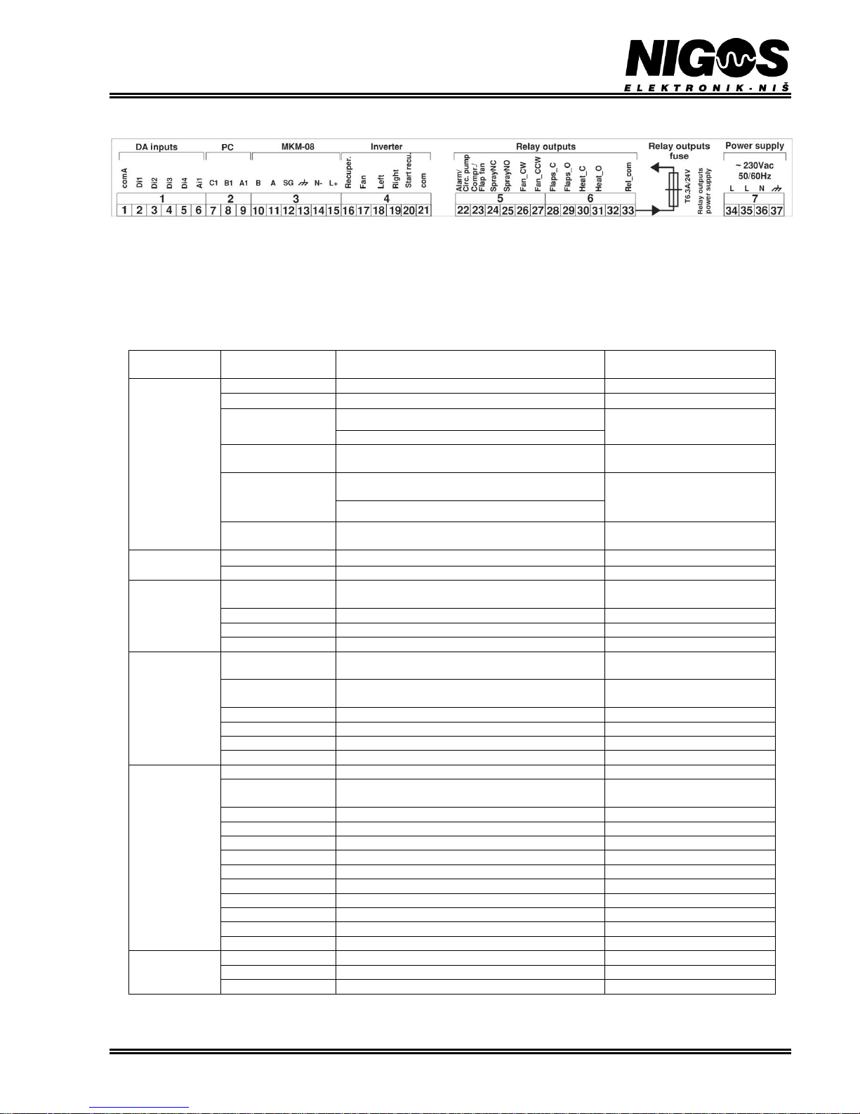
Picture 2.2. MC-2000 clamps layout
Controller MC-2000 is not intended for "stand alone" operation like model MC-600 or MC-502R, but is instead delivered as an integrated part
of switch board. It comes already wired to clamps in the switch board. All cables are connected via 3-pol and 6-pol clamps labeled with
numbers 1 to 9 and connected to appropriate clamps of MC-2000.
User must connect equipment in the chamber to appropriate clamps in power electric switch board according to given layout and schemes
provided with switch board.
Table 2.1. MC-2000 clamp connection layout
CLAMP
LABEL
NUMBER/
CLAMP LABEL
CONNECTED TO CLAMP
FUNCTION
Digital /
Analogue (DA)
inputs
1/ comA
Flow fans, heat pumps 1-3 and temperature probe
Common contact
2/Di1
Voltage-free contact on switch for flow fan
Circulation fan operation control
3/Di2
External pause (conv.)
External pause /
Heat pumps operation control
Fan on compressor
4/Di3
Voltage-free contact on circulation pump
Circulation pump operation
control
5/Di4
Voltage-free contact on switch for fan in flap or
recuperator (conv.)
Fan in flap operation control /
Recuperator operation control
Heat pump pressostat (cond.)
6/Ai1
Temperature probe Pt1000
Input for temperature of
incoming water, evaporator, etc.
PC
7/C1
Communication ground
Ground
8,9/RS-485 (B1, A1)
RS-485 (B, A) on PC computer (RS adapter)
Pc computer communication
MKM-08
10, 11,12 / RS-485
(B, A, SG)
RS-485 (B, A, SG) on MKM-08 box
Communication with MKM-08
box
13/ GND
GND on MKM-08 box
MKM-08 box ground
14/ N-
N- on MKM-08 box
MKM-08 box null
15 / L+
L+ on MKM-08 box
MKM-08 box power
Inverter
16/Recuperator
Inverter for recuperator
DC voltage proportional to
speed
17/Fan
Inverter for flow fan
DC voltage proportional to
speed
18/Left
Inverter for flow fan
Left direction
19/Right
Inverter for flow fan
Right direction
20/Start recu.
Inverter for recuperator
Recuperator start
21/com
Inverter
Inverter ground
Relay outputs
22/Alarm/Circ.pump
Alarm signal or circulation pump start
Alarm / Circulation pump
23/Compr. /
Flap’s fan
Switch for compressor or flap’s fan inverter
Compressor or fan in flap ON
24/Spray_NC
Not connected
NC for spraying
25/Spray_NO
Spraying valve
Spraying valve open
26/Fan_CW
Switch for right direction of fans (in switch board)
Right direction of fans
27/Fan_CCW
Switch for left direction of fans (in switch board)
Left direction of fans
28/Flaps_C
Servo drive on flap
Servo flap closing
29/Flaps_O
Servo drive on flap
Servo flap opening
30/Heat_C
Heating valve
Heating valve closing
31/Heat_O
Heating valve
Heating valve opening
32
Not connected
Not connected
33/Rel_com
Control voltage from power switch board
Control voltage
Power supply
230V *
34,35/L
Power cable line
MC-2000 power supply
36/N
Power cable null
MC-2000 null
37/GND
Power cable ground
MC-2000 ground
* Digital inputs can be used for signaling the state of the various pieces of equipment. This shows the initial schedule, or it can be changed
depending on the type of dryer and installed equipment.
Page 4
EQUIPMENT FOR MEASUREMENT&CONTROL AND DRYERS
B. Nikolica-Serjoze 12, 18000 Nis, Serbia; Phone/Fax:+38118 211-212, 217-468; [email protected]; www.nigos.rs
4 Automatic control unit MC-2000 (version 5.4.6)
2.3. MC-2000, MKM-08 AND DS-04t INTERCONNECTION
MKM-08 is a communication box that converts obtained measured values from EMC, MC and temperature probes and transfers converted
data to MC-2000 controller. Conversion of the measured signals from the probes into a more suitable form, performed inside the MKM-08
box, is necessary for long-distance data transfer. Connection between MC-2000 and MKM-08 is carried out via communication cable SF/UTP
CAT.5E 4 pairs or LIYCY 3x0.5mm2, with the maximum distance between them of 300m. Special communication protocol for digital
communications between these units has been developed by NIGOS developing team, according to standard RS-485.
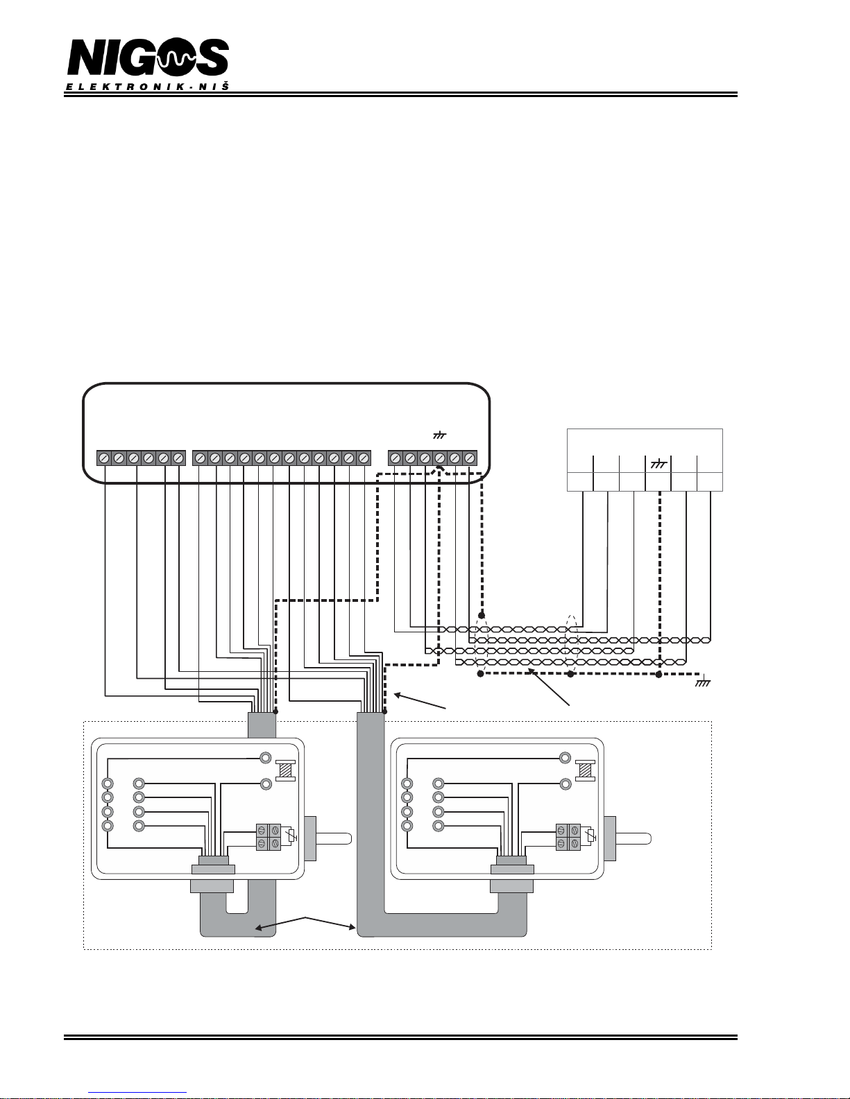
Cables used for connecting system components (MC-2000, MKM-08 and DS-04t) must have appropriate length and diameter. They are
connected according to the schematic on the figure 2.4. It shows clamps layout in each box. The clamps are available after removing
protection cover. Cable colors are standard for the cables that are used and delivered by NIGOS-elektronik, and that rule should be obeyed
whenever it is possible. In cable remain 4 unused wires – green, pink, violet and orange.
NOTES:
1. Measurement and communication cables from picture below should go separately from energy cables with minimal distance
between them of 30 cm. In cases where these cables must cross energy cables, it is ONLY permitted to cross them at 90°
(perpendicularly).
2. MKM-08 box must be grounded! When prefabricated panel chamber is used, ground MKM-08 box in near vicinity (*). When brick
chamber is used, ground MKM-08 box at power electric board end (**). Communication (SF/UTP or LIYCY 3x0.5mm2) cable must
be shielded and this shield must be connected to ground at one end only.
For standard MC-2000 configuration with 8 wood MC probes, settings should be as shown on the picture below. Important note is that here is
shown connection to controller’s clamps and not to switch board clamps, but corresponding clamps must be used in both situations.
SG
A
B
N-
L+
121110 13 14 15
M K M -08
300m max
30m max
(**)
LI6YC6Y
12x0.34mm
2
Vd7
Vd8
Vd5
Vd6
COM
MKM-08v2
Vd3
Vd4
Vd2
COM
GND
GND
COM
COM
Vd1
T1
T2
V2
V1
SG
A
B
L+
*
N-
Pt1000 Pt1000
DS-04t(1) DS-04t(2)
S2 S6
S1 S5
S3 S7
S4 S8
CD CD
BROWN BROWN
WHITE WHITE
GRAY GRAY
BLUE BLUE
BLACK BLACK
RED RED
YELLOW YELLOW
EMC EMC
Pt1000 Pt1000
REDRED
MKM clamps
on MC-2000
DRYING CHAMBER
BROWN (S2)
WHITE (S5)
WHITE (S1)
GRAY (S4)
GRAY (S8)
YELLOW (S7)
YELLOW (S3)
BROWN (S6)
RED (CD)
RED (CD)
BLACK (T1)
BLACK (T2)
TRANSPARENT (GND)
TRANSPARENT (GND)
BLUE (V2)
GREEN/GREEN-WHITE (N-)
GREEN/GREEN-WHITE (N-)
SHIELD (GND)
YELLOW-GREEN (GND)
SHIELD(GND)
BLUE-WHITE (B)
BLUE-WHITE (B)
BLUE (A)
BLUE (A)
BROWN/BROWN-WHITE (L+)
BROWN/BROWN-WHITE (L+)
ORANGE/ORANGE-WHITE(SG)
ORANGE/ORANGE-WHITE(SG)
BLUE (V1)
Wood MC
TRANSPARENT TRANSPARENT
Wood MC
YELLOW-GREEN (GND)
Picture 2.4. Schematic of DS-04t to MKM-08 connection, and MKM-08 to MC-2000 communication cable connection
As shown on the picture 2.1, DS-04t boxes are installed inside the drying chamber. They are connected to MKM-08 via LI6YC6Y 12x0.34
mm2. MKM-08 box is mounted on the outer wall of the kiln regarding that the distance (and the cable length) to both DS-04t boxes is as short
as possible. Connecting boxes that way provides that all disturbances that affect data transmission of the temperature, EMC and MC data
signals are reduced. Maximal length of the used connection cables is 30 m.
Page 5
EQUIPMENT FOR MEASUREMENT&CONTROL AND DRYERS
B. Nikolica-Serjoze 12, 18000 Nis, Serbia; Phone/Fax:+38118 211-212, 217-468; [email protected]; www.nigos.rs
Automatic control unit MC-2000 (version 5.4.6) 5
2.4. CONNECTION OF TEMPERATURE, EMC AND 8-POINTS MC MEASUREMENT SET
In the standard configuration, measuring set for temperature, EMC and 8points wood MC is included with MC-2000 controller. This measuring set
consists of one MKM-08 box, two boxes DS-04t, probes, sensors and
appropriate cables.
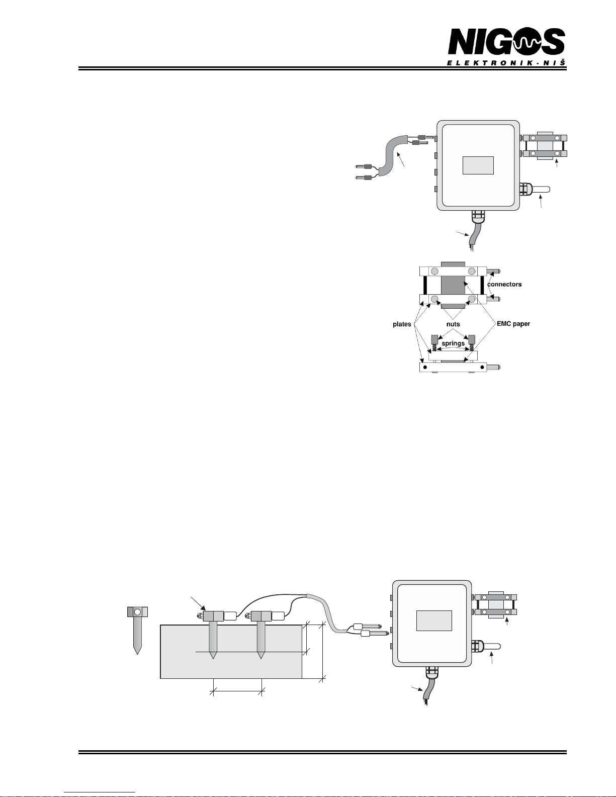
DS-04t box is made to provide connection of temperature probe,
equilibrium moisture content (EMC) probe and four wood moisture (MC)
probes to communication box MKM-08. DS-04t boxes are placed inside
the drying chamber, MKM-08 is placed outside.
Temperature measurement: Temperature probe (sensor) Pt1000 is used
for temperature measurement. This probe is mounted inside the DS-04t
box in NIGOS factory, and is connected to printed circuit board UGL-01
which is also mounted inside the DS-04t box. See picture 2.4 for
LI6YC6Y 12x0.34mm2 cable connection.
Equilibrium Moisture Content (EMC) measurement: Two hole-plugs,
marked EMC, are placed on the top of the DS-04t box. They are for
connecting EMC paper holder and DS-04t box, as shown on picture 2.5.
EMC paper is rectangular shaped and made of special hydroscopic
material. Since one EMC paper-element is used for ONE drying cycle
only, it should be discarded after it, and new one should be fitted when a
new drying cycle starts. Certain amount of this paper (sufficient for
exploitation in period of 1 to 2 years) is delivered to user upon delivery of
other equipment. Additional amounts of the paper are provided when
needed or during regular service. Unused EMC paper should be stored on
a dry and dark place.
EMC paper fitting sequence: Unscrew nuts on the paper holder, so the
springs remain free. Place new EMC paper between aluminum plates.
Screw nuts back to achieve good coherence between EMC paper and
aluminum plates.
NOTE: EMC paper is used for ONLY ONE drying cycle. That means,
after each drying cycle is finished, the old EMC paper should be discarded
and replaced with new one according to given instructions
Sensor
Pt1000
MC probe
attachment
cable
EMC paper
holder
LI6YC6Y
12x0.34mm
2
FEP/SILICON
2x0.75mm
2
DS-04t
EMC
MC1
MC2
MC4
MC3
Temp
Picture 2.5. Connection of the measurement elements to
DS-04t and EMC paper holder
Measurement of wood moisture content (MC) in 8 points: 8-points MC measurement set consists of 4 connection cables and a set of wood
moisture probes. These probes are multiple-time-use INOX nails.
Drying process is primarily based on average wood MC that is obtained from 8 different measuring spots. Therefore, proper fitting of the
probes in the wood and their symmetrical disposition inside the chamber is most important.
STAINLESS STEEL NAIL PROBES SET-UP (probes for multiple use):
These are stainless steel (INOX) - multiple use probes. After each drying cycle they must be carefully taken out of timber and saved for later
use. They are replaced with new ones only in case of mechanical damage. Each MC probe has one pair of stainless steel nails. Recommended
lengths of nails are: 30 mm used for lumber up to 40 mm thick (thin lumber); 45 mm used for lumber above 40 mm thickness (thick
lumber). One pair of probes is used for each MC measurement point. Probes are hammered in the lumber perpendicularly to board at distance
of 30 to 35 mm (optimally 32 mm). A pair of holes Ø3.2 (3 ÷ 3.5) mm should be drilled in the lumber before hammering the probes. Depth
should be 15 mm shorter than the probes' length. Probes should be than hammered into the holes whit paying attention that the depth of
penetration must not be smaller than 1/3 of board depth (1/2 of board depth is best). In case when thin and soft lumber is used, user does not
need to drill holes, but he can hammer the probes directly into the lumber. Probe cable is connected on the other side to the patch board (DS04t) placed on the wall, inside the drying chamber.
17 ÷ 25 mm
30 mm ÷ 35
50 mm
Wood MC probe
attachment cable
Wood MC probe
FEP/SILICON 2x0.75mm
2
UGL
Sensor
Pt1000
EMC sample
holder
Li6YC6Y
12x0. mm34
2
EMC
MC1
MC2
MC4
MC3
Temp
DS-04t
Picture 2.6. Proper placement of INOX wood MC probes in 50mm board and connection to DS-04t box
Page 6
EQUIPMENT FOR MEASUREMENT&CONTROL AND DRYERS
B. Nikolica-Serjoze 12, 18000 Nis, Serbia; Phone/Fax:+38118 211-212, 217-468; [email protected]; www.nigos.rs
6 Automatic control unit MC-2000 (version 5.4.6)
3. OPERATION
3.1. MC-2000 FRONT PANEL LAYOUT
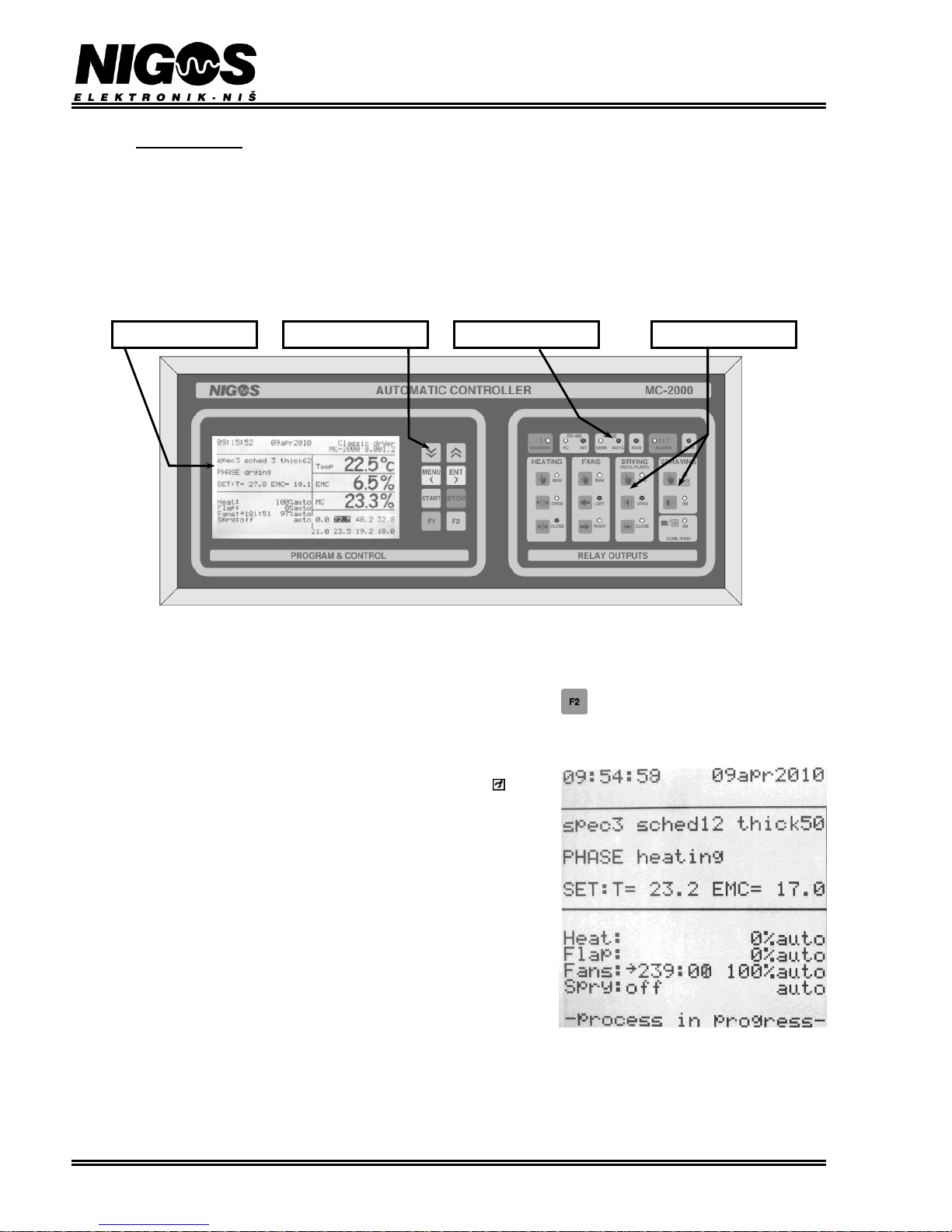
MC-2000 front panel includes:
In section PROGRAM & CONTROL:
- One 16-rows x 40-characters LCD display (5 different languages supported)
- 8 control buttons (DOWN, UP, MENU, ENT, START, STOP, F1 and F2)
In section RELAY OUTPUTS
- 11 buttons for manual control of the outputs
- 17 LED diodes as indication of various states of controller and relay outputs
Front panel layout is shown on the next picture, while functions of displays, buttons and diodes are given in following text.
3.1.1. LCD display functions
LCD display has 16 rows with 40 characters in each row. During normal operation of the controller, this display shows all relevant messages
regarding operation process for controller-user interaction. Sequential pressing of the button cycles few most often used menu options.
- First row shows time and date which is periodically replaced with selected type of dryer, manufacturer name and programmer signature.
- Second row shows software version. Symbol which describes access level is displayed
bellow date. If there is no symbol - controller is locked. If there is a symbol shown,
then access to advance settings is enabled. Look chapter 3.8 for more information and
details.
- Fourth row displays selected parameters for wood type, drying regime and wood
thickness.
- Sixth row describes current phase of drying process
- Eighth row displays set points for temperature (T) and equilibrium moisture content
(EMC).
- Eleventh to fifteenth row display control equipment state in form label / state / mode.
Mode can be auto or man depending if automatic or manual operating mode is
selected
Opening percentage is displayed for heating and flaps (dampers) output
State for fans can be: stopped (stop), paused (x), working left (<) or working
right (>). Aside from this, remaining operation or pause time and fan speed (if inverter is
installed) is displayed. If user has set the fan speed manually, then fan mode is displayed
as semi.
For spraying and compressor output state displays phase of active function and remaining / elapsed operating time. In case ECON
mode is selected for compressor, label E will be displayed. Display for compressor can be replaced with display for fan in flap (if installed
instead of compressor).
- Last row displays standard messages (operation progress) and warnings and alarm situation if one occur.
LCD display
LED diodes
Control buttons
Output control buttons
Page 7
EQUIPMENT FOR MEASUREMENT&CONTROL AND DRYERS
B. Nikolica-Serjoze 12, 18000 Nis, Serbia; Phone/Fax:+38118 211-212, 217-468; [email protected]; www.nigos.rs
Automatic control unit MC-2000 (version 5.4.6) 7
3.1.2. Temperature, EMC and wood MC display
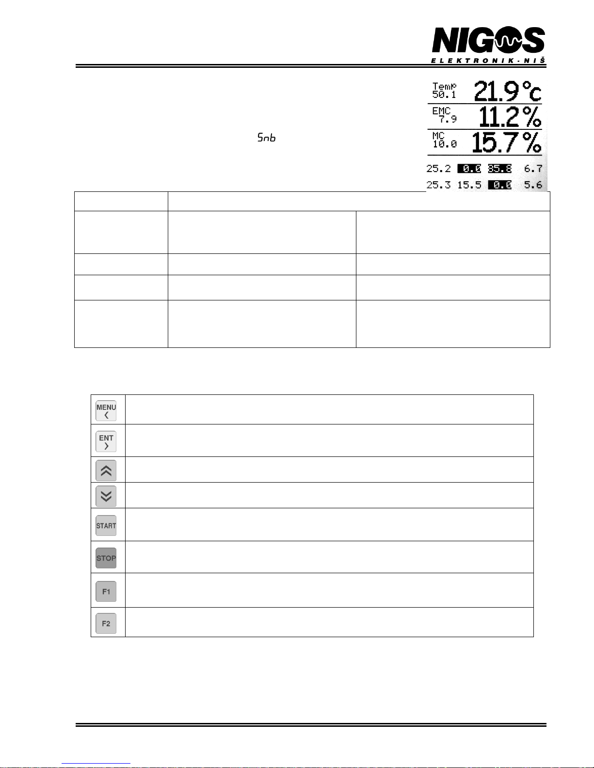
Right section of LCD display always show currently measured temperature (Temp), equilibrium
moisture content (EMC) and average wood moisture content (MC) in the drying chamber. Below is a
section where actual MC value from each wood MC probes is displayed.
In case displays for temperature and EMC show label it indicates that appropriate probes are not
connected, or improper values are measured. In that case alarm is activated.
Table 3.1. Temperature, EMC and wood MC display
LCD DISPLAY
LABEL
DISPLAYS
Temperature (Temp)
Display is in range -20°C to 120°C:
- From -20.0 to 99.9°C display has one decimal point
- From 100 to 120°C display show integer values
Shows average value of measured air temperature
obtained from active temperature probes ( 1 or 2)
Equilibrium moisture
content (EMC)
Display is in range 0.0% to 30.0% with one decimal
point
Shows average value of measured equilibrium moisture
content obtained from active EMC probes (1 or 2)
Wood moisture content
(MC)
Display is in range 0.0% to 100% with one decimal
point for values under 100%
Shows average value from all active probes (up to 8)
Measurement point
Display is in range 0.0% to 100% with one decimal
point for values under 100%
Shows wood moisture obtained from each MC probe.
Active probes are normally shown (black numbers on
light background), while passive probes are shown
inversely (black background with light numbers).
Probe which is turned off is shown with dashes.
3.1.3. Buttons function
Pressing some of the 8 buttons placed on the controller's front panel activates: parameter adjustments, starting or stopping of the system, etc.
- Used for ENTER/EXIT into menus and CANCEL unwanted changes.
- CONFIRMATION of menu option selection and parameter change acceptance.
- INCREASES the value of currently selected parameter or LIST menu options upwards.
- DECREASE the value of currently selected parameter or LIST menu options downwards.
- System START-UP, i.e. starts drying process.
- Short press on the button cause system SHUT-DOWN, i.e. stops drying process.
- Long press on the button cause system PAUSE, i.e. pause drying process
- In standard display mode - resets all alarms if there are any.
- During event history display - switches from basic to extended view mode and vice versa.
- In regime display mode copies the antecede value
- Cycles most important menu options (displays required temperature and EMC values if the process is started in
automatic mode / menu Probes MC / menu Control / return to basic display mode).
Page 8
EQUIPMENT FOR MEASUREMENT&CONTROL AND DRYERS
B. Nikolica-Serjoze 12, 18000 Nis, Serbia; Phone/Fax:+38118 211-212, 217-468; [email protected]; www.nigos.rs
8 Automatic control unit MC-2000 (version 5.4.6)
3.2. "RELAY OUTPUTS" FRONT PANEL SECTION
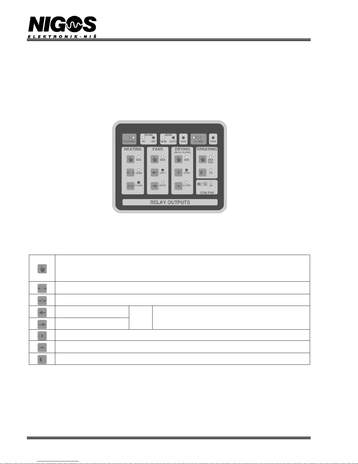
Group of buttons and diodes in "RELAY OUTPUTS" section of the controller are used for manual control of kilns equipment, as well as
indication of their state.
This section include:
- 11 buttons for manual control
- 20 LED diodes for indication of output's states.
Front panel layout is shown on the next picture, while buttons and LED functions are explained separately, afterwards.
3.2.1. Buttons function
Pressing some of the buttons on RK-08A front panel will activate appropriate function (indicated by appropriate LED diode flashing). Pressing
again will cancel the function. Buttons' functions are given in next table:
- Manual mode activation for outputs: heating (HEAT), flow fans (FANS) and flaps (dampers) (FLAPS)
- This button has double function for spraying output (SPRAY). First pressing activates manual spraying control (diode is
constantly lit). With second pressing controller enters testing mode for sprayers (diode flashes) - spraying output is
periodically activated and paused until the button is pressed again and spraying output is turned off.
- Heating valve opening.
- Heating valve closing.
- Left direction of flow fans
}
There is a pause before each direction change, which is indicated by
flashing of diode FANS > MAN
- Right direction of flow fans
- Drying flaps (dampers) opening
- Drying flaps (dampers) closing
- Activation of spraying valve
Page 9
EQUIPMENT FOR MEASUREMENT&CONTROL AND DRYERS
B. Nikolica-Serjoze 12, 18000 Nis, Serbia; Phone/Fax:+38118 211-212, 217-468; [email protected]; www.nigos.rs
Automatic control unit MC-2000 (version 5.4.6) 9
3.2.2. Signaling LED diodes
There are 8 LEDs which indicate controller’s states during operation.
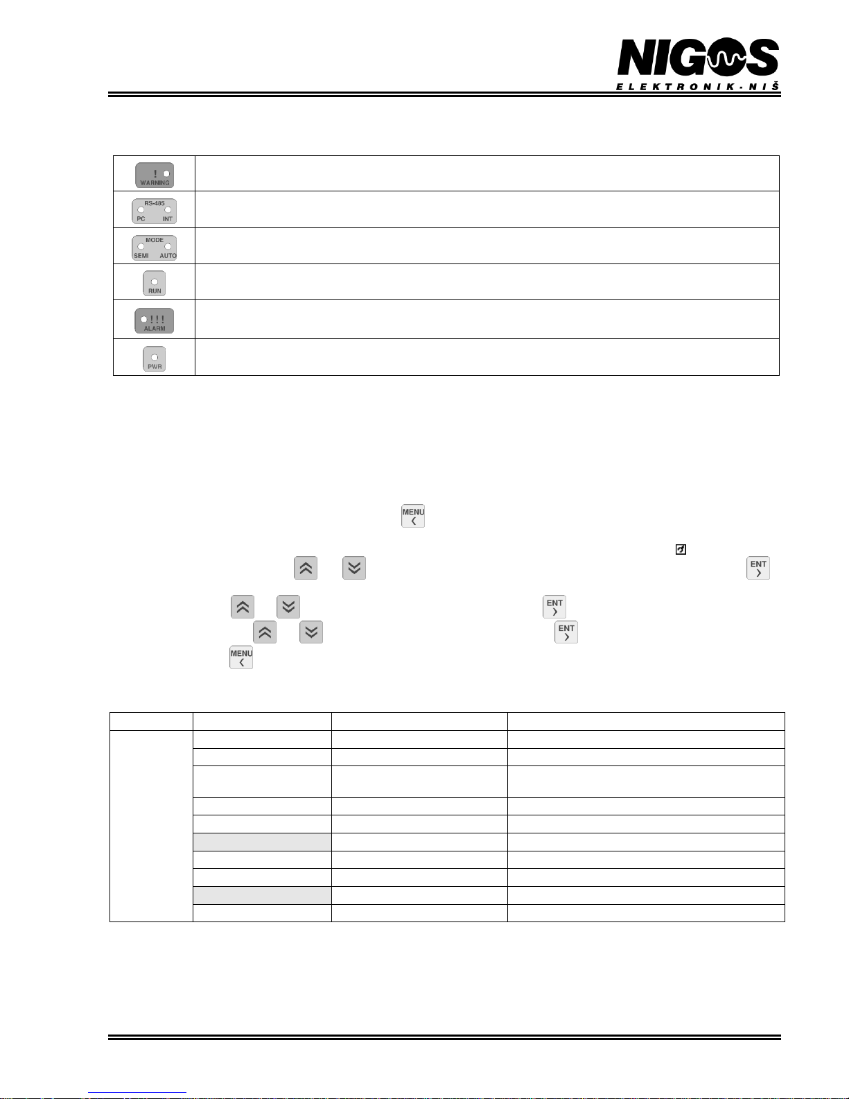
- flashing of diode WARNING (!) indicates the presence of some warning situations
- diodes RS-485 (PC or INT) indicate communication activity (with PC or communication unit MKM-08)
- diode AUTO indicates automatic operation mode of the controller
- diode SEMIAUTO indicates semi-automatic operation mode of the controller
- flashing of diode RUN indicates beginning of the drying process (measuring phase)
- later, it lights constantly until drying process is finished or system is stopped
- diode ALARM (!!!) indicates the presence of some alarm situation which pauses drying process
- diode PWR indicate that power supply is connected to controller
LED diode placed next to each button indicate activity on corresponding output. When lit, output is active. When turned off, output is inactive.
Only exception from this behavior have:
- diode next to button for manual control of spraying output which flashes when spraying system testing mode is active.
- diode for manual change of fan’s direction which flashes during pause between direction change and
- diode for compressor / fan in dumper output which flashes while waiting for operation confirmation or pause.
3.3. PARAMETER SETTINGS
In order to change any parameter, user must press the button to enter main menu. Each menu has multiple options which are accessible
and visible on the LCD display depending on the selected access level. Based on the label which is shown below current date, it is easy to
conclude whether the controller is locked (nothing is displayed) or advanced level access is enabled (there is symbol shown here). Menu
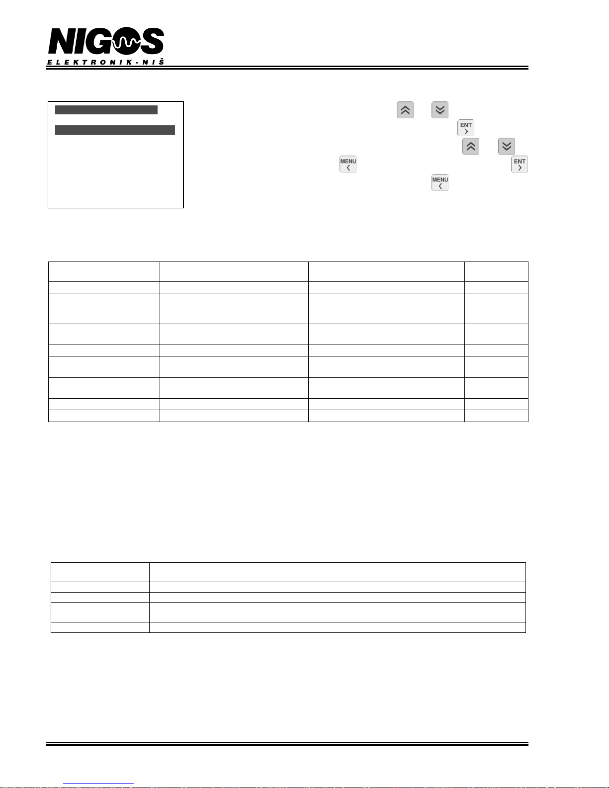
options can be scrolled using buttons and . Currently selected option (or parameter) is shown inversed. Press the button in
order to select an option. This enters the sub-menu which contain list of available parameters. When in this list, it is possible to scroll the
parameters using buttons and , and select the parameter for changing by pressing . When certain parameter is selected, its value
can be changed using buttons and . If certain value is changed pressing the button will confirm the acceptance of the change.
In same situation button has a function to cancel the any changes made and return to prior sub-menu. If same button is pressed again,
controller will return to standard display. In case no button is pressed in 4 minutes, controller will also cancel the change and return to standard
display.
Free access
Code protected access
M E N U
Drying param
Drying param
Drying parameter setting
Probes
Probes
Probes state setting
Control
Control
Displays measured temperature and EMC from all
probes as well as temperature on control inputs
History
History
Displays archived data
Statistics
Statistics
Displays statistical data
REGIMES
Regimes overview and setting
SETUP
SETUP
Controller setup
Kiln type
Kiln type
Kiln type setting
Oscillation drying
Oscillation drying mode selection
Access
Access
Access level setting
Page 10
EQUIPMENT FOR MEASUREMENT&CONTROL AND DRYERS
B. Nikolica-Serjoze 12, 18000 Nis, Serbia; Phone/Fax:+38118 211-212, 217-468; [email protected]; www.nigos.rs
10 Automatic control unit MC-2000 (version 5.4.6)
3.3.1. Option: Drying parameters
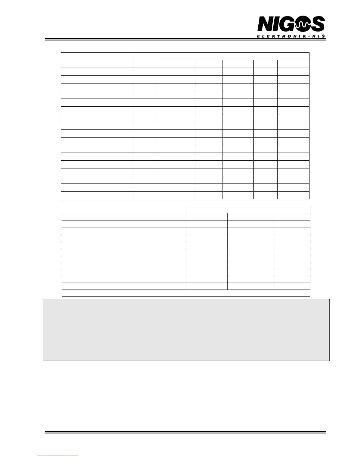
This option is used for drying parameters setting. Buttons and are used for parameter
scrolling (display is now as shown on the picture), pressing the button will select the
parameter, and changing of the parameter value is performed using buttons and . To
cancel performed change, press the button and to confirm the change, press the button .
After all desired changes are made and confirmed, press the button to exit this option and
return to upper sub-menu. These parameters can be changed even during drying process.
It is required to set all parameters from this option when automatic drying mode is used. For semiautomatic mode only correct setting of WOOD TYPE parameter is required.
Following table shows all parameters in this option.
Table 3.2. Parameters of Drying param option
PARAMETER
LABEL
DESCRIPTION
RANGE OF
PARAMETER VALUES
DEFAULT
VALUE
OPERATING MODE
Operating mode
semi, auto
auto
TIMBER GROUP
Type of wood. Measurements will be
made according to this value (see Table
3.3.)
1 , 2 , 3 , 4
3
SCHEDULE
Schedule (regime) according to which
drying will be controlled
From 1 to 20
1
THICKNESS/mm
Lumber thickness
From 20 to 80 mm
50
HEAT TIME/h
Time to maintain certain temperature
during pre-heating phase
From 0 to 100 h
(adjustable in 1 h steps)
0
FINAL MC
Final wood moisture that has to be
achieved at the end of drying
From 5.0 % to 30.0 %
(adjustable in 0.1 % steps)
13.0
EQUALIZATION
Allow equalization phase during drying
no, 1, 1.5, 2, 3
no
CONDITIONING
Conditioning phase permission
yes, no
no
3.3.1.1. Parameter: OPERATING MODE
This parameter defines in which mode the controller will operate. When it is set to automatic mode, the controller will follow the selected
drying schedule (regime). In semiautomatic mode, the user must set desired values for air temperature and humidity, and the controller will
maintain them at the constant level. There are two diodes below LCD that display selected mode all the time. For semiautomatic mode LED
SEMI is lit, while LED AUTO is lit when automatic mode is selected.
3.3.1.2. Parameter: TIMBER GROUP
It is necessary to define the type of the wood that is dried in order to achieve proper wood moisture content (MC) measurement. All wood
species are divided into 4 groups, which are given in the next table.
Table 3.3. Table of wood types and related groups of wood species according to which the MC measurement is made
WOOD
TYPE
WOOD
SPECIES
1
Zebrano, Cork, Rubber Tree
2
Beech, Poplar, Lime, Iroko, Niangon, Ebony, Olive
3
Pine, Ash, Birch, Larch, Locust, Acacia, Mahogany, Oak, Sappeli, Walnut, Maple, Chestnut, various fruit
trees...
4
Dibetou, Kapur, Sipo, Utile
3.3.1.3. Parameter: SCHEDULE
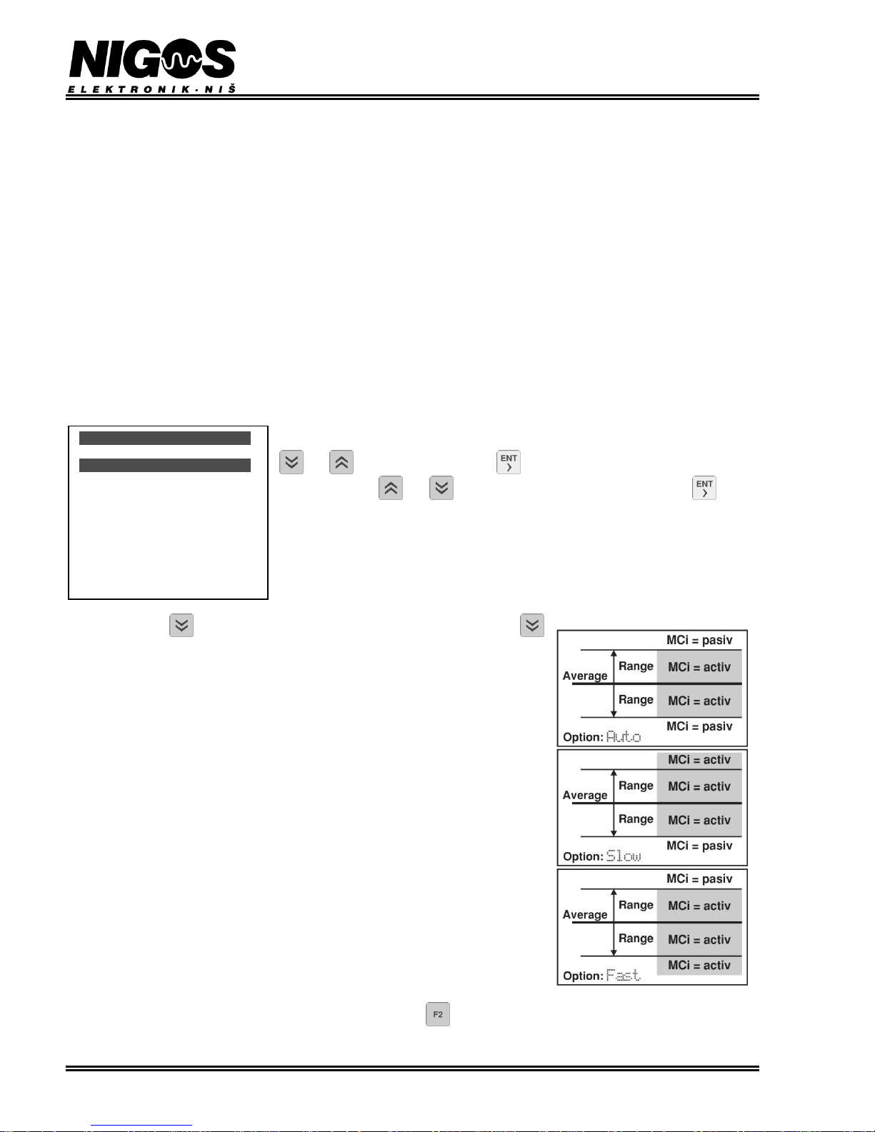
Parameter SCHEDULE is used to select schedule (drying regime) that will be used in drying process control. Schedule can follow automatic
drying based on measured wood MC or time. Each regime defines temperature and EMC curves (relations between chosen parameter - T or
EMC, and time), fan’s speed, temperature gradient for heating, temperature and humidity setpoints for conditioning phase and duration of the
conditioning phase. All schedules are made for lumber thickness of 50 mm. Changing of the regimes is available only at advanced access
level, using options SCHEDULE from main menu.
Upon drying process start-up, controller will automatically adjust drying process to selected schedule and kiln type.
Drying param
OPERATING MODE auto
TIMBER GROUP 3
SCHEDULE 9
THICKNESS/mm 50
HEAT TIME/h 0
FINAL MC 13.0
EQUALIZATION no
CONDITIONING no
Page 11
EQUIPMENT FOR MEASUREMENT&CONTROL AND DRYERS
B. Nikolica-Serjoze 12, 18000 Nis, Serbia; Phone/Fax:+38118 211-212, 217-468; [email protected]; www.nigos.rs
Automatic control unit MC-2000 (version 5.4.6) 11
Table 3.4. Table of drying regimes pre-defined by "NIGOS - elektronik"
DEDICATED REGIMES
CONVENTIONAL DRYER
Slow
Average
Fast
Softwood
41
42
43
Beech, steamed
44
45
46
Oak, sessile
47
48
49
Douglas
11
41
42
Lamella < 10 mm
50
56
57
DEHUMIDIFYING DRYER
Slow
Average
Fast
Softwood
53
54
55
Soft hardwood
52
53
54
Hard hardwood
52
52
53
Lamella < 10 mm
56
57
Lamella by EMC (without wood probes)
58
IMPORTANT WARNING FOR USING PRE-DEFINED SCHEDULES!!
Drying regimes which are inserted in controller’s memory by default (schedule 1 to 12) are based on both significant practice knowledge of
drying wood and laboratory testing made in well-known wooden industries. Since there are many factors that can influence drying process
such as wood origin, quality of wood, wood surface conditions, stock height, stock assemblage, etc... - drying characteristics for certain lumber
can differ from the one used for creating schedule. That is why we recommend strict monitoring of drying process to achieve both maximum
efficiency in drying progress and proper parameter settings for your type of wood.
NIGOS - elektronik do not accept responsibility for any faults on the timber (bent, crack, twist, etc...) or any accidental situation
during drying process caused by either operator's negligence or disregarding process, even when the manufacturer's pre-defined
drying regime is used.
3.3.1.4. Parameter: THICKNESS/mm
This parameter defines average thickness of the lumber, which is to be dried. It is necessary to set this parameter value properly for normal
progress of drying process. Drying schedules and curves are pre-defined for lumber 50 mm thick. Thinner lumber require faster schedule and
vice versa, for thicker lumber drying schedule should be slowed down. Adjusting the parameter value to actual lumber thickness (if possible)
provides that the controller performs all rest relevant schedule settings automatically.
Speeding of drying process for thickness lower then 50 mm is
done by following:
- values for moisture curve are decreased
- temperature ramp ratios are increased.
Slowing of drying process for thickness higher then 50 mm is
done by following:
- values for moisture curve are increased,
- temperature ramp ratios are decreased.
Calculations are made in percentage relative to the thickness in millimeters.
WOOD SPECIES
Group
FACTORY REGIMES
Very slow
Slow
Average
Fast
Very fast
Fir, Spruce
3
17
22
27
28
30
Pine
3
16
21
22
28
30
Larch
3
16
21
22
28
30
Beech, steamed
2
16
17
18
19
24
Beech, natural
2
11
12
13
14
15
Beech, white
2 / 3 4 5
10
Oak, slavonian
3 6 11
12
13
19
Oak, sessile
3 2 3 4 9
14
Ash
3 7 11
12
14
20
Poplar
2
11
17
21
22
28
Linden
2
11
16
17
18
23
Birch
3
11
16
17
18
23
Cherry
3
11
12
17
18
20
Acacia
3
11
12
17
18
19
Walnut
3
11
12
17
18
19
Mahogani
3
11
12
17
22
23
Samba
2
21
22
27
28
34
Page 12
EQUIPMENT FOR MEASUREMENT&CONTROL AND DRYERS
B. Nikolica-Serjoze 12, 18000 Nis, Serbia; Phone/Fax:+38118 211-212, 217-468; [email protected]; www.nigos.rs
12 Automatic control unit MC-2000 (version 5.4.6)
3.3.1.5. Parameter: HEAT TIME/h
Drying of certain wood species (especially certain exotic species and hard woods) require core heating, i.e. it is required to equal wood core
temperature with surface temperature. When drying temperature is achieved (during heating phase), this parameter can be used to set the time
for which the controller will maintain this temperature before allowing drying to start. Parameter value is in hours (0 to 100 h in steps of 1 h).
After each drying cycle is over, this parameter is reset to 0 (off).
3.3.1.6. Parameter: FINAL MC
Defines desired final wood moisture content value at the end of the drying process.
3.3.1.7. Parameter: EQUALIZATION
Determines if equalization will be performed during drying and the range of equalization. It is applied on active probes only. If value no is
selected, automatic controller will not perform equalization. If for example, value 2 is selected, then controller will try to maintain that all
probes are within final wood MC ±2% from it.
NOTE: This function can significantly extend drying time and successful ending depends on the ability of wood dryer to provide desired
conditions!
3.3.1.8. Parameter: CONDITIONING
Parameter CONDITIONING defines whether conditioning phase will be performed after drying phase or not. Relevant parameters that define
this phase closely are given within the selected schedule.
3.3.2. Option: Probes MC
This option shows measured value and state of all MC probes labeled with MC1 MC8. Attached
probes will be listed here with shown state for each probe (active or passive). To list probes, use
and , and select one by pressing , after which it is possible to change the probe's
state using buttons and . To confirm change of the probe state button must be
pressed.
Active state of the probe indicates that information (MC or temperature) received from MKM-08
from this probe will be taken in count. Passive state indicates that this value is discarded in
average value calculation.
When drying is selected, average value is calculated based on the data received only from active
probes and drying process is controlled based on this value. Controller does not allow putting all
the probes in passive state. At least one of them must be active.
It is possible to turn off certain probes from poling and listing when controller is unlocked. In that
case pressing button will set the probe in passive state, and next pressing on the button
turns the probe off.
Parameter Calc mode/MC determines how average wood MC is calculated. It can be calculated
as average (Avg), auto (Auto), slow (Slow) and fast (Fast). Additional calculation of average
wood MC according to which drying process is run as well as setting the state of wood MC
probes in either active or passive state depends on value of parameter Auto cut off/%
according to following principle:
- Avg: Value for wood MC is calculated as average value of probes that are set in active state.
Passive probes are not taken into calculation. User sets probes in active or passive state by
himself (manually).
- Auto: This option will automatically put in passive state all probes that measure too high or
too low values. Principle is following: Controller will collect values from all probes and
calculate average of all probes. This value is increased and decreased by value of parameter
Auto cut off/% to define upper and lower range. All probes (MC1 to MC8) which have
values within this range are set in active state, while all probes that are outside this range are
set into passive state. New average is then calculated based on active probes and it becomes
valid average for running the drying process. Controller puts probes in active or passive
state automatically.
- Slow: This option is used to slow down drying process. When selected – it will automatically
set to passive state all probes that measure too low moisture content. Those are probes that
measure MC bellow lower range defined by parameter Auto cut off/%.
- Fast: This option is used to speed up drying process. When selected – it will automatically
set to passive state all probes that measure too high moisture content. Those are probes that
measure MC above higher range defined by parameter Auto cut off/%.
Option Probes MC can be accessed directly with pressing of the button .
Probes MC
MC 1 29.06 activ
MC 2 20.28 activ
MC 3 18.62 activ
MC 4 27.47 activ
MC 5 8.54 pasiv
MC 6 25.27 no
MC 7 20.91 activ
MC 8 19.23 activ
Calc mode/MC avg
Auto cut off/% 40
Page 13
EQUIPMENT FOR MEASUREMENT&CONTROL AND DRYERS
B. Nikolica-Serjoze 12, 18000 Nis, Serbia; Phone/Fax:+38118 211-212, 217-468; [email protected]; www.nigos.rs
Automatic control unit MC-2000 (version 5.4.6) 13
3.3.3. Option: Control
LED displays always show average value for temperature and EMC. Option Control gives
overview of current measurement values for all temperature and EMC probes and control inputs. Each
probe can be set to passive or active state, with limitation that at least one temperature and at least one
EMC probe must be always active. Same like in the option Probes, it is possible to turn off certain
probes from poling and listing.
If only one temperature/EMC probe is installed, then for the one that is not attached, label "off" is
displayed. In case the probe measure fault value, label "error" is displayed.
Parameters Calc mode/Temp and Calc mode/EMC determine how average temperature and
EMC will be calculated. It can be calculated as minimum (min), maximum (max) or average (avg).
Parameters Diff T1-T2 and Diff EMC1-EMC2 define allowed difference of temperature and
EMC reading between installed probes. If difference is greater than this value, warning will be
displayed.
Below this, control temperatures are displayed. When the control probe is attached and measures temperature in the range -25 to 200 °C,
measured value is displayed. Otherwise, label "----" is displayed. There are 4 control inputs for temperature measurement.
If the controller is unlocked, it is possible to turn off probes from listing. Press the button to set the probe into passive state, and press the
button again to turn off the probe. Probes should be turned off only if they are not installed or malfunctioning.
Option Control can be accessed directly with pressing of the button .
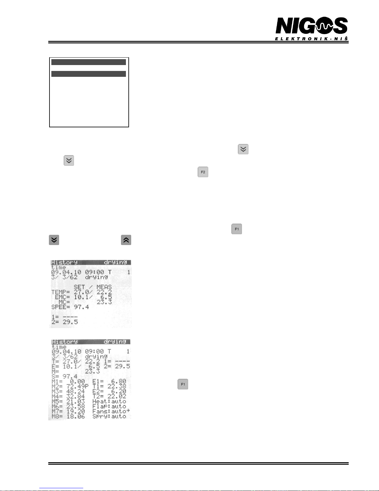
3.3.4. Option: History
Controller will store data essential for drying progress reconstruction in certain time interval. User can set this time to 2, 3, 4 or 6 hours.
Beside saving data in equal time interval, controller also saves critical data upon each start-up and always when certain alarm situation which
cause drying process pause. Controller’s memory can store more than 15.000 records, which is enough for more than 2 years or normal
operation of dryer. When the memory is full, oldest records will be overwritten first, then newer ones.
When this option is opened, only simple (short) overview is available. Push the button to see extended (complete) view of history. Button
lists older data, while button lists newly dated records.
Simple view:
- First row informs the user that history is selected.
- Second row explains type of record: timing or restarting.
- Third row displays time of archiving and drying turnus ordinal (only when user level access is
enabled).
- Forth row shows information regarding selected wood type, chosen regime and wood thickness
(T/R/D). In semiautomatic mode, label "S" is displayed for chosen regime. Phase of the process is
displayed next.
- Set/measured temperature (TEMP), equilibrium moisture content (EMC), average wood MC (MC)
and set speed for fans (SPEE) are displayed below.
- If there are any control temperature inputs connected to system, measured temperatures are
displayed below labeled with 1 to 4 for each input.
Complete history view:
Complete history view shows all data shown when simple history view is selected, plus a lot more.
All wood MC probes are listed here (M1 M8). If any probe is set to passive state, then the label P is
shown behind the measured value. Also, values from each temperature probe (T1 and T2), as well as
EMC probes (E1 and E2) are shown. In addition, mode of operation (auto/semi) is shown for
each control output.
Pressing the button can switch views from simple to complete and vice versa in any time.
3.3.5. Option: Statistics
Several statistical parameters regarding dryer operation are shown here. Upper part of the display shows total operational time of the fans,
sprayers and compressor. Time is shown in minutes. Lower part displays same data, but only for last drying cycle. Last row shows number of
drying cycles (drying cycle ordinal).
Control
EMC 1 11.21 activ
Temp1 46.37 activ
EMC 2 9.03 activ
Temp2 48.62 pasiv
Calc mode/Temp avg
Calc mode/EMC avg
Diff T1-T2 10
Diff EMC1-EMC2 7
Contr.temp ----
Page 14
EQUIPMENT FOR MEASUREMENT&CONTROL AND DRYERS
B. Nikolica-Serjoze 12, 18000 Nis, Serbia; Phone/Fax:+38118 211-212, 217-468; [email protected]; www.nigos.rs
14 Automatic control unit MC-2000 (version 5.4.6)
3.3.6. Option: SETUP
slobodan pristup
pristup sa šifrom
S E T U P
System
parameters of drying system
Spraying
parameters of spraying system
Compressor
Compressor
parameters of compressor
Recuperator
parameters of additional equipment for drying
Fans
Fans
parameters of fan control
Time/Date
setup for current time and date
IO device
setup for comunication
3.3.6.1. Option: SETUP > Compressor
Ova opcija je namenjena kondenzacionim sušarama gde je instaliran kompresor. Opcijom Econ mod
aktivira se ili isključuje eko mod rada kompresora.
3.3.6.2. Option: SETUP > Fans
This option displays status of the fans and gives options for their setup.
Parameter Change direct.? enables change of fans (and consequently air flow) direction. After
this option is activated by setting yes, fans will stop, wait for pause time to pass and then start rotating
in the opposite direction.
When parameter Set spee is set to auto, user can not set fan speed, but instead controller
determine fan speed according to selected drying regime. When set to semi, user can set fan speed
regardless the automatic mode.
For direction change to have an effect, appropriate equipment that support it must be installed.
Same applies for speed regulation which require inverter to be installed.
Parameter Set speed semi/% enables manual setting of fan speed in percentage (0 100%).
Parameter Revr period/min defines reversion time in minutes. Fans will rotate in one direction
and change it (reverse) after this time. Fan pause/min defines length of pause between change.
Parameter Max speed/% defines maximum operating speed of fans in percentage (0 - 100%).
This option becomes visible only after controller is unlocked at user access level.
It is possible to set different time for reversion during spraying. The reason is that more frequent reversion of fans during spraying provide
more uniform humidification of timber. Parameter Spray chng revr will override setting of parameter Revr period/min when
spraying is active. If value of parameter Spray chng revr is set to no, then there is no change of reversion time set by parameter Revr
period/min. But if the value is set to 10 to 60 minutes, it will over-ride the setting defined by Revr period/min and will become valid
time for fan’s reversion period when spraying is active.
Below these parameters, fans status is displayed. Fans can be: stopped (stop), paused (x), rotating counter-clockwise - left («) or clockwise right (»). Next to this state, remaining time for operation or pause is displayed. Number in percentage represent current fan speed in case
frequency inverter is installed. In case fans speed is manually entered, last label in this row displays semi.
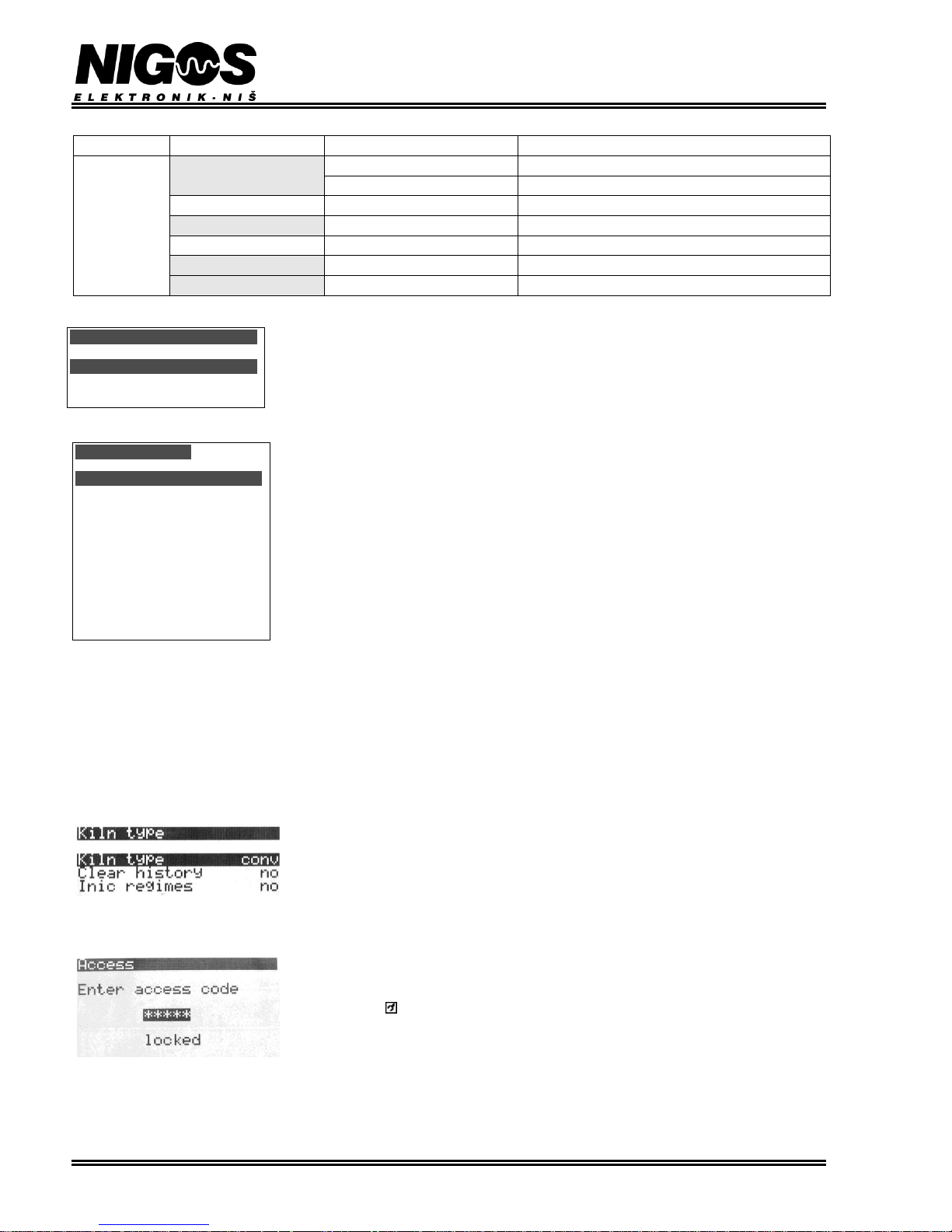
3.3.7. Option: Kiln type
This option defines kiln type and consequently the way controller operate. Possible values for
parameter Kiln type are conventional (CLAS) or dehumidifying (COND).
Parameter Clear history deletes all records in history.
Parameter Inic regimes return all regimes to their factory default settings.
3.3.8. Option: Access
Option Access is used for setting access level to the unit and its options and parameters as well.
Entering correct access code unlocks the unit and makes access to advanced level possible. Symbol
which describes access level is displayed bellow date. If there is no symbol - controller is locked. If
there is a symbol shown, then access to advance settings is enabled.
More details regarding this option are available in Chapter 3.8.1.
Compressor
Econ mod(cond) no
0:00 auto
Fans
Change direct.? no
Set speed auto
Set speed semi/%100.0
Revr period/min 240
Fan pause/min 3
Max speed/% 100
Spray chng revr no
State
»173:45 93%auto
Page 15

EQUIPMENT FOR MEASUREMENT&CONTROL AND DRYERS
B. Nikolica-Serjoze 12, 18000 Nis, Serbia; Phone/Fax:+38118 211-212, 217-468; [email protected]; www.nigos.rs
Automatic control unit MC-2000 (version 5.4.6) 15
3.4. OPERATING MODES
3.4.1. Automatic, semiautomatic and manual mode
3.4.1.1. Automatic mode
To select automatic mode, go to MENU > Drying param option, then choose Operating mode parameter end select auto.
In automatic mode, before starting the drying process, user must set all parameters in MENU > Drying param option. It means automatic
mode, wood type, drying regime, lumber thickness, heat time, final wood moisture content and conditioning options must be set. All these
parameters are very important, because on the basis of those data and chosen regime unit can lead the drying process and determine required
setpoints in every moment. Some of these parameters can be changed during process.
Drying process runs according to chosen drying regime. 20 different regimes can be defined, but only 8 of them are user-programmable. On
advanced access level, user or authorized person can define drying regimes according to expert's claims. After the start of drying process
(performed by pressing the button and confirming start by selecting - yes), user should survey system periodically. It is recommended
that user register any alarm situation timely, and to take action in accordance with emergency procedure (described in Chapter 3.7) if the
situation is urgent.
3.4.1.2. Semiautomatic mode
To choose semiautomatic mode, go to MENU > Drying param option, then choosing OPERATING MODE parameter end select semi.
In semiautomatic mode, user must set only two parameters in option MENU > Drying param. Semiautomatic mode and wood type must be
selected. Remaining parameters in this option are not relevant for controller operation in semiautomatic mode. Immediately after
semiautomatic mode is selected, controller gives the user opportunity to adjust set values for temperature and EMC ( SET:T= ---- EMC=
---- ). User must set these parameters based on the personal experience and wood MC measured by controller. To enable parameter setting,
LCD display must be in text or graphic basic display mode.
Pressing the button cycles through selection of temperature and EMC which is labeled in inverse color of selected parameter. Value
adjustment is performed using buttons and . To confirm parameter change, button must be pressed. After desired values for
temperature and EMC in semiautomatic operation mode are entered, user must press button to exit adjustment option, which is
automatically happening if no button is pressed for 4 minutes.
In semiautomatic mode, user must periodically check actual values for temperature and EMC in the chamber and wood MC and based on these
data, update set values for temperature and EMC. Set value for temperature can be in range 0 0C to 70 0C (up to 100 0C on user request), while
EMC can be set in range 0% EMC to 30% EMC. In semiautomatic mode, there is no heating phase - drying phase starts immediately. User
himself decide when to end drying, and weather he wants conditioning phase (and sets conditioning parameters).
MC-2000 will control heating valves and drying flaps on his own, so alarm situations may occur, and if does, user should register them and if
necessary make interventions according to instructions given in Chapter 3.6.
3.4.1.3. Changing of operating mode (auto to semiauto and vice versa)
Changing of operating mode is available in MENU > Drying param option by choosing OPERATING MODE end selecting desired mode as
parameter. When you change operating mode from automatic to semiautomatic, controller preserves last calculated temperature and EMC
setpoints from automatic mode, so activity of control outputs stays same like before the change. When you activate automatic mode from
semiautomatic, controller turns off all outputs for about 20 seconds (reduced measuring phase) and after that it calculates new setpoint values
and proceed with operation.
3.4.1.4. Manual mode
Manual mode is available through the group of buttons located on RK-08A box (i.e. right side of the MC-2000 controller labeled with
"RELAY OUTPUTS". Disregarding current operating mode, at any time of drying process you can choose manual control of heating, drying
or spraying function by pushing corresponding button for each output separately. Short pressing of the button always change the state of
output (turn on/off). If the output is turned off, and button is pressed and hold down, output will become active (turn on). As soon as the button
is released, output will be deactivated (turned off).
There is no need to set all outputs to manual mode, but only the one that is related to output we want to control manually. During this time,
automatic control unit stays in selected operating mode.
There are two buttons related to output for heating valve (one for opening, one for closing the valve), two for output for flaps (opening and
closing) and also two for fans direction change (left and right).
Spraying system has a little different setting. Button for spraying has double function: first pressing activates spraying system (LED diode
is lit constantly), while second pressing will evoke spraying test (LED diode flashes) during which output will be automatically turned on and
off until button is pressed again and spraying test ended.
All outputs are activated (turned on) after first press of appropriate button (LED diode is lit), and stay active until they are deactivated after
second press of button (LED diode turned is turned off).
Page 16
EQUIPMENT FOR MEASUREMENT&CONTROL AND DRYERS
B. Nikolica-Serjoze 12, 18000 Nis, Serbia; Phone/Fax:+38118 211-212, 217-468; [email protected]; www.nigos.rs
16 Automatic control unit MC-2000 (version 5.4.6)
3.5. DRYING PROCESS START UP
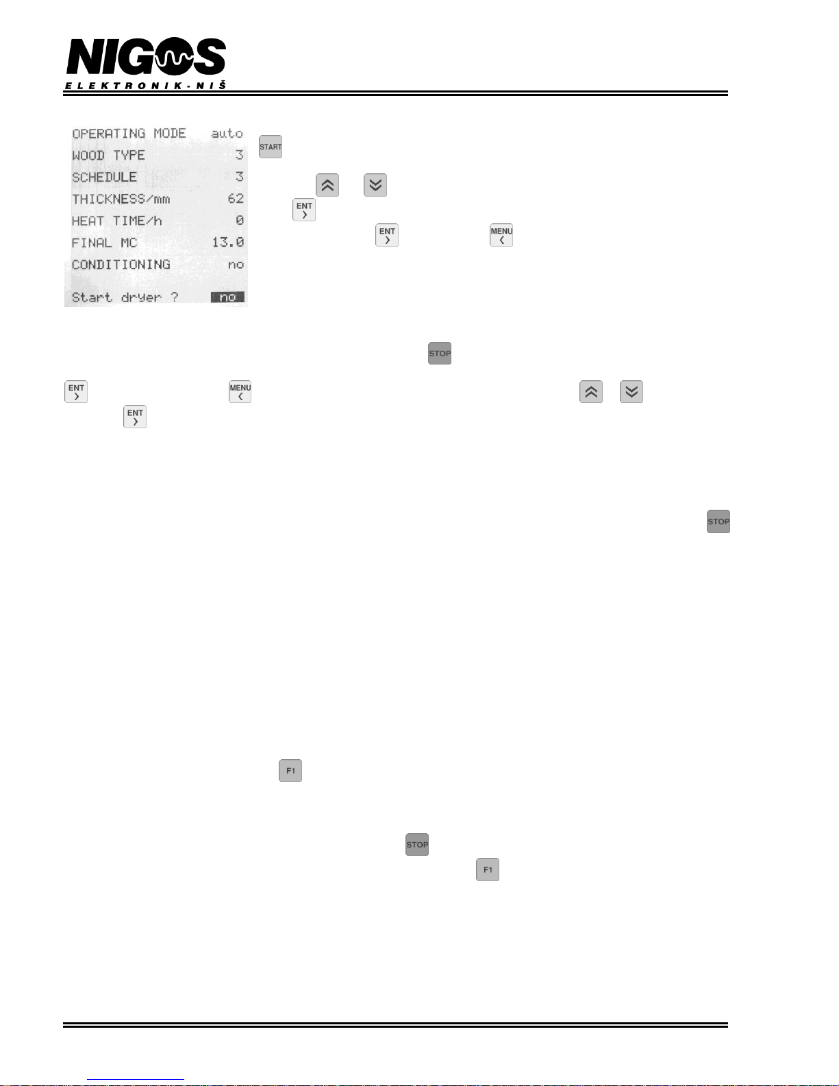
When all required parameters for drying process are set, system can be started by pressing the button
. After this, all parameters are displayed above the question Start dryer ?. Default value
is always no . User can check all relevant parameters once more and if everything is all right, use
the buttons and to change the answer to yes and confirm the change by pressing the
button . After that system is started. If you do not want to start drying, you can either choose
answer no and press the button or press the button no matter which answer is chosen.
3.6. STOPPING DRYING PROCESS
While system is running, you can stop the drying process by pressing the button. After pressing this button, automatic control unit
responds with showing drying parameters and asks: Stop dryer? Default answer is no. You can accept offered answer by pressing either
with selected answer no, or button to continue the process, or choose answer yes using button or and confirm it by
pressing the button to immediate stop drying process. After that, all control outputs turns off and process is stopped.
We emphasize that the system should be stopped that way only if user considers the drying process is finished. If you want to stop
drying process temporary, you can switch off power supply to stop the drying. After restoring power, the unit continues process
automatically from where it was interrupted.
3.7. PAUSING DRYING PROCESS
Sometimes is needed to pause drying process without stopping whole system. Pausing just drying can be done by long pressing button
when drying is already active and when controller displays main menu. Pressing this button, pause drying process and display current phase as
Phase: pause as well as text ! paused ! at bottom of display. After that, all outputs are turned off and drying process is paused.
Valves and flaps will be closed. System leaves paused mode and continues process after process start-up as it is described in Chapter 3.5 in
this manual.
Pausing system is very similar to power cut or stopping, but difference is that starting of invertors and flow fans is available if system
is paused, not stopped. Another, more important difference is that pausing will not increment number of drying cycles, while stopping
will increment it.
3.8. WARNINGS AND ALARM SITUATIONS
During drying process some unwanted situations could occur. The unit is programmed so that it could recognize some irregular situations and
announce them by showing certain messages on LCD. If the unit can identify the problem, it shows a proper message in the last row of LCD.
Simultaneously, LED indicator ! (WARNING) blinks to notify the warning state. These warnings don't stop drying process, but make user pay
attention to the situation and take action. Simultaneously with light indication, controller activates sound alarm output. Sound alarm is active
certain period of time, and then deactivated, while light warnings are shown on display as long as the situation is present, or until the message
is revoked.
The warning can be cancelled by pressing the button.
Alarm situation causes pause of the drying process, because the ensued situation does not allow the process to be continued. Simultaneously
with announcing the situation, LED indicator !!! (ALARM) blinks and alarm output (that can activate either sound or light signalization) turns
on. In that case, user must intervene to revive the system, if possible. In case user can not find out a reason for alarm, user should contact
manufacturer or authorized person that maintain the system. Pressing the button resets alarm output.
Alarm message is present on LCD until the reason of alarm is eliminated. Pressing the button can revoke the alarm message, but it will
be activated again if the reason of alarm persists. In that case, user should apply defined procedure for eliminating alarm situation that is
presented in table 3.6. After the alarm reason is eliminated, the unit passes a new measuring phase and continues the drying process until
desired values are reached.
Whenever an alarm situation is ensued, some data are stored in system archives. This leaves an option for subsequent examination of archive,
which can help discovering the problem.
If more then one either warnings or alarms ensue during process at the same time, they will be displayed on LCD alternately every 2 seconds.
All alarm and warning messages that can appear on LCD during drying process are given in next table. Also, there are some procedures that
the unit performs independently, or either user or authorized person should perform to eliminate the problem.
Page 17
EQUIPMENT FOR MEASUREMENT&CONTROL AND DRYERS
B. Nikolica-Serjoze 12, 18000 Nis, Serbia; Phone/Fax:+38118 211-212, 217-468; [email protected]; www.nigos.rs
Automatic control unit MC-2000 (version 5.4.6) 17
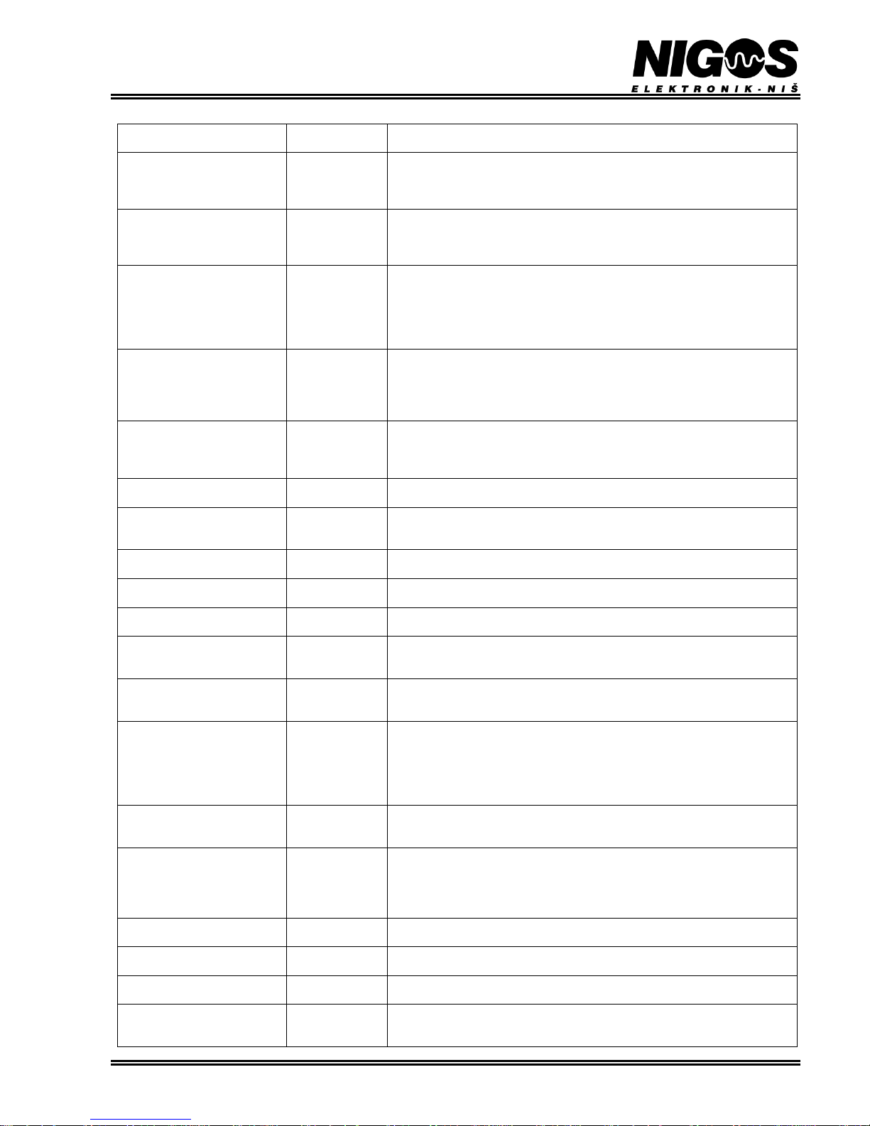
Table 3.6. List of possible warning and alarm messages
MESSAGE
TYPE
MESSAGE DESCRIPTION
AND RECOMMENDED ACTIONS
fan failure?
Warning
There is a problem (or problems) in functioning of one or more fans. Activities of
fans are always checked at start of drying process.
These messages don’t cause the system pausing. Authorized person should check
notified fans.
flaps fan ?
Warning
There is a problem with fans in flaps. Activities of fans are always checked at
start of drying process.
These messages don’t cause the system pausing. Authorized person should check
notified fans.
temp holdback HI
temp holdback LO
Warning
In case that measured value exceeds allowed deviation of setpoint, one of these
warnings on LCD appears. All outputs are operational, but drying process is
stopped until the warning is active. In that case, you should compare temperature
value in the kiln, shown on LCD, with a manually obtained value, if it is possible.
Check the temperature probes and the rest of equipment in the kiln. If needed,
consult authorized person.
-overheat
Alarm
This alarm activates when temperature in the kiln becomes higher than maximal
drying temperature (Max drying temp) for more than 10 C. It causes
system pausing. Only cooling is enabled during that state. When temperature
drops to Max drying temp + 2 C, controller will continue drying.
Check the heating valve. Consult authorized person.
-underheat
Alarm
This alarm activates when temperature in the kiln becomes lower than minimal
drying temperature (Min drying temp) for more than 2 C. It causes system
pausing. Both cooling and drying are disabled.
Check the heating boiler and valve. Consult authorized person.
temp low for spraying
Warning
Temperature has dropped bellow minimum at which spraying is allowed.
Find the reason for temperature drop.
diff temp1-temp2 ?
Warning
If both temperature probes are active, this warning will signal that there is great
difference between them. User must check the temperature probes and find
possible cause for this difference.
temp probe 1 ?
temp probe 2 ?
Warning
One of the temperature probes is measuring improper value. If the other probe is
working properly, the system discards the first one and continue working.
-temp probe ?
Alarm
Warning that both temperature probes failed and measurement is wrong. It causes
system pausing and all equipment is shut down. Service is obligatory!
EMC holdback HI
EMC holdback LO
Warning
These messages appear when measured EMC exceeds allowed limits.
Check EMC probes, flaps and sprinklers.
diff emc1-emc2 ?
Warning
If both EMC probes are active, this warning will signal that there is great
difference between them. User must check the EMC probes and find possible
cause for this difference.
emc probe 1 ?
emc probe 2 ?
Warning
Signalizing that one of the EMC probes is measuring improper value. If the other
probe is working properly, the system discards the first one and continue
working.
-emc probe ?
Alarm - in
drying,
conditioning and
pre-heat phase.
Warning - in
other phases
Warning that both EMC probes failed and measurement is wrong. It causes
system pausing and all equipment is shut down.
Service is obligatory!
wood probe x ?
(x = 1 8)
Warning
Signalizing that one of the wood MC probes (1 of 8) is measuring improper
value. Set this probe to passive state and continue working. At least one probe
must stay active.
-wood probes error
Alarm - in
automatic mode.
Warning - in
semiautomatic
mode
All wood MC probes measure incorrect values.
Check wood MC probes, connection cables and connection boxes.
In semiautomatic mode, this alarm has no influence.
compressor temp
Warning
Temperature in the chamber is bellow minimal temperature required for
compressor operation. Find the reason for low temperature.
compr x malfunction
(x = 1 3)
Warning
Warning that compressor x (from 1 to 3) is malfunctioning.
Call authorized service or NIGOS. Service is obligatory!
-compress error
-compress malfunction
Warning
Compressors won't start or they have turned off during operation.
Call authorized service or NIGOS. Service is obligatory!
-comm error MKM
Alarm
Messages reporting error in communication between controller and MKM box.
Possible causes are equipment malfunction (MKM box) or split communication
cable.
Page 18
EQUIPMENT FOR MEASUREMENT&CONTROL AND DRYERS
B. Nikolica-Serjoze 12, 18000 Nis, Serbia; Phone/Fax:+38118 211-212, 217-468; [email protected]; www.nigos.rs
18 Automatic control unit MC-2000 (version 5.4.6)
-comm error PC
Warning
Messages reporting error in communication between controller and PC computer.
Possible causes are equipment malfunction or split communication cable.
-SMB error
-SPI error
-boot error
-code error
-strings error
-CSM memory error
Warning
System messages. User has no influence and if these messages are reported by the
controller, authorized service or NIGOS must be contacted immediately. Service
is obligatory!
! paused !
Alarm
Drying process has been started, but system is paused due to an alarm
appearance. This message is shown on LCD whenever a warning that causes
system pause is present.
Obligate service
Controller has detected some error and recommends obligatory service.
Authorized service or NIGOS must be contacted immediately.
3.9. ADDITIONAL ADJUSTMENTS
Controller MC-2000 has a number of functions that provide some additional adjustment. Due to possible irregular operation of the controller
these functions are hidden, and regular user cannot access them, but only experience users and authorized personal. Access to this advanced
access level is possible after a correct code is entered in the Access option.
3.9.1. Option: Access
Option Access is used for setting access level to the unit and its options and parameters as well.
Entering correct access code makes unlocking of the unit and progress to advanced level possible. As
an indication that the control unit is unlocked, LCD in home view shows symbol placed bellow
current time and date. While controller is locked, there is no display here.
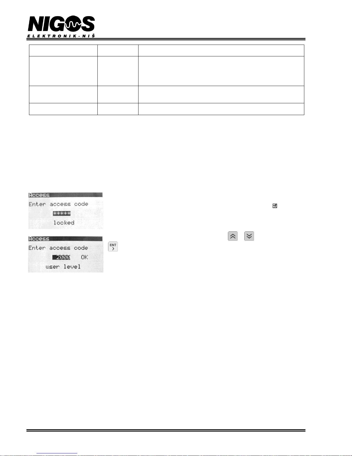
When option Access is activated, LCD shows message: Enter access code, 5 asterisks
(*****) and current access level state (locked / user level). If none of buttons is pressed
within 50 seconds, system gets locked automatically. When user wants access to advanced level to be
granted, correct value for access code must be set using the or buttons, and pressing the
button after that. Default value for access code (set by manufacturer) is 2000 and user can
change it by using parameter Access Code, in the option MENU>SETUP>System. If the entered
code is correct, message user level is displayed on LCD. In any other case the unit remains
locked and home view is shown on LCD.
NOTE: User should use this option with extreme caution, because there are only three chances to enter the correct code. If you
fail three times, controller will get permanently locked and you will not be able to unblock it at all (even entering correct code
can not unblock it!). In that case you should contact either NIGOS or authorized person.
Page 19
EQUIPMENT FOR MEASUREMENT&CONTROL AND DRYERS
B. Nikolica-Serjoze 12, 18000 Nis, Serbia; Phone/Fax:+38118 211-212, 217-468; [email protected]; www.nigos.rs
Automatic control unit MC-2000 (version 5.4.6) 19
3.9.2. Option: REGIMES
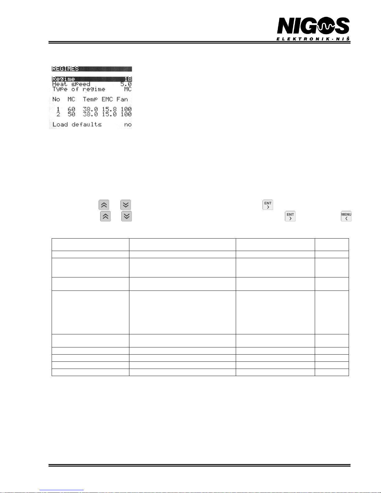
Option REGIMES becomes visible when the controller is unlocked (correct code is entered in option
Access level).
This option defines regimes used in automatic operation mode for appropriate wood specie. Total of
20 regimes can be defined, where first 12 regimes are pre-defined by manufacturer and can not be
changed, while remaining 8 are free for change according to user's needs. Changing of the particular
regime is available only at advanced access level, using options REGIMES.
Each regime defines temperature and EMC curves (relations between chosen parameter - T or EMC,
and time), temperature gradient for heating, minimal drying temperature, temperature and EMC
setpoints for conditioning phase and duration of the conditioning phase. All regimes are made for
lumber thickness of 50 mm. User regimes must be also made for lumber 50mm thick because controller automatically change EMC curve,
temperature gradient for heating and conditioning time. The thinner the boards, the faster the regime will be (EMC curve is steeper), and vice
versa - for thicker boards, regime will be slowed down (EMC curve becomes milder).
Special situation occur when user has no data for lumber 50mm thick, but only for some other thickness he uses all the time. In that case he
can make a regime using that data for that specific wood type and that specific thickness. But, in order to avoid change of the regime data, he
must select thickness of 50 mm for parameter THICKNESS/mm in option Drying param. Regime defined in this manner should be used
ONLY for drying of that specific wood type and thickness.
Option REGIMES displays symbolic name and regime ordinal and temperature gradient during heating phase. Below is a table view of
temperature curves (Temp), EMC curves (EMC) and fan speed (Fan) for specific wood MC (MC). Conditioning parameters are displayed at
the bottom: duration of the conditioning phase (Duration/h), temperature (Temp), EMC (EMC) and fans speed during conditioning phase
(Fans). Use buttons and to list all parameters (showed in inverse). Press the button to change the value of the selected
parameter. Use buttons and to set the parameter value, and confirm the change by pressing button . Pressing the button
will cancel any change made to selected parameter and return to previous menu.
Table 3.7. Parameters of REGIME option
PARAMETER
LABEL
DESCRIPTION
RANGE OF
PARAMETER VALUES
DEFAULT
VALUE
Regime
Regime ordinal
From 1 to 60 (40)
1
Heat speed (²C/h)
Rate at which heating temperature will raise
(heating temperature ramp rate) given in °C
per hour
From 0.1 0C/h to 10.0 0C/h
2.5
Type of regime
Description of type of regime. Can be wood
MC or time based.
MC, TIME
No
Number of column in selected regime. 2
columns are displayed. Ordinals 1 to 12 show
parameters of regime, while last column
(Cond) show conditioning parameters.
NOTE: When conditioning parameters are
shown, first value is duration of conditioning
phase (instead of MC).
From 1 to 12, Cond
1
MC (%) (in 5% steps) *
Specific wood MC for which temperature and
EMC data is used
From 60.0 %MC to 5.0 %MC
60
Temp (²C) *
Temperature for selected wood MC
From 10.0 0C to 80.0 0C
28
EMC (%) *
EMC for selected wood MC
From 2.0 % to 30.0 %
20
Fan (%) *
Fan's speed for selected wood MC
From 0.0 % to 100.0 %
100
Load defaults
Loading of default settings
yes, no
no
* - these parameters are per regime and only in regimes from 1 to 12.
Page 20
EQUIPMENT FOR MEASUREMENT&CONTROL AND DRYERS
B. Nikolica-Serjoze 12, 18000 Nis, Serbia; Phone/Fax:+38118 211-212, 217-468; [email protected]; www.nigos.rs
20 Automatic control unit MC-2000 (version 5.4.6)
3.9.3. Option: SETUP
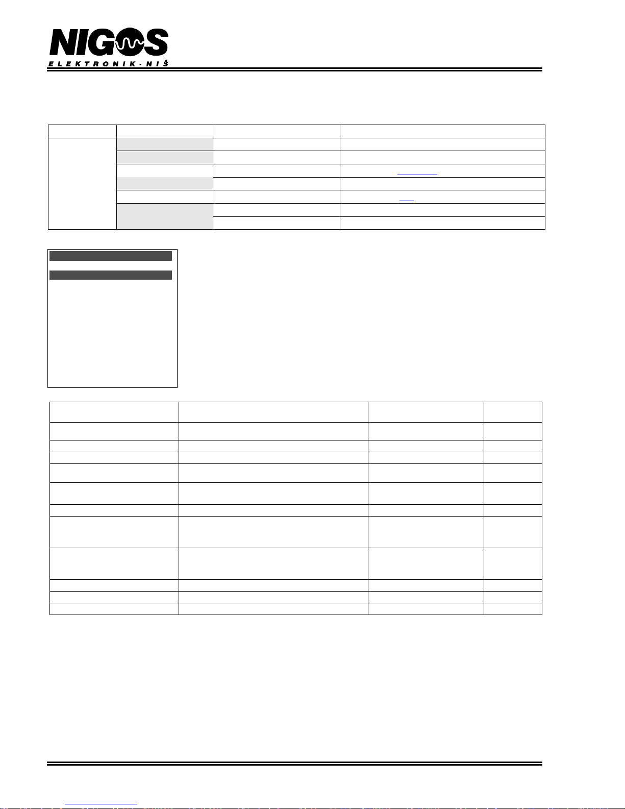
Ovo je stavka za razna podešavanja na automatu. Ovo je podmeni iz kojeg se bira stavka koju treba podesiti. Nakon otključavanja
automata na korisničkom nivou (pristup sa šifrom) su vidljive sledeće stavke:
slobodan pristup
pristup sa šifrom
SETUP
System
parameters of drying system
Out Spraying
parameters of spraying system
Compressor
Compressor
parameters for compressor
Rekuperator
parameters for additional drying equipment
Fans
Fans
parameters for fans
Time/Date
set up current time and date
IO device
set up communications
3.9.3.1. Option: System
Option System provides adjustment of certain system parameters. Each change of these
parameters should be taken with extra caution and change should be documented. This
especially apply to change of access code (parameter User code), because access to any
advanced settings of the controller will become impossible if access code is changed and
then forgotten.
Table 3.8 shows all parameters in this option. Initial values (default values) are different depending on
the chosen dryer type. If "default value" column contains two values, first always apply for
conventional and second for dehumidifying dryer.
Table 3.8. Parameters of System option
PARAMETER
LABEL
DESCRIPTION
RANGE OF
PARAMETER VALUES
DEFAULT
VALUE
Language
Language choice
srpski, english,
russian
srpski
User code
Access code for advanced level
0 to 65535
2000
DryTempRampRate
Temperature ramp rate in drying phase
0.1 0C/h to 10.0 0C/h
10.0
Max temp/² (²C) (*)
Maximal temperature in drying phase
30.0 0C to 80.0 0C
65.0 /
55.0
Temp end/² (²C)
Defines how much temperature should reduce
when drying ends
-50.0 0C to -0.1 0C
-10.0
CoolTempRampRat(²C/h)
Temperature ramp rate in cooling phase
0.1 0C/h to 10.0 0C/h
2.0
Temp holdback/%
Measured/set temperature deviation ratio (in %).
When the value is exceeded, system freezes at its
current point, waiting for process to catch up.
1 % to 50 %
20
EMC holdback/%
Measured/set EMC deviation ratio (in %). When
the value is exceeded, system freezes at its current
point, waiting for process to catch up.
1 % to 50 %
30
Arhive time/h
Data archiving interval
2 h, 3 h, 4 h, 6 h
3
Warning delay/min
Delay for warning report
0 min to 120 min
10
Alarm delay/min
Delay for alarm report
0 min to 60 min
3
(*) - when compressor is present, parameter Max temp/² can be set to maximum 65.0°C.
System
Language englis
User code 2000
DryTempRampRate 10.0
Max Temp/² 65.0
Temp end/² -10.0
CoolTempRampRat 2.0
Temp holdback/% 25
EMC holdback/% 30
Arhive time/h 3
Warning delay/min 10
Alarm delay/min 3
Page 21
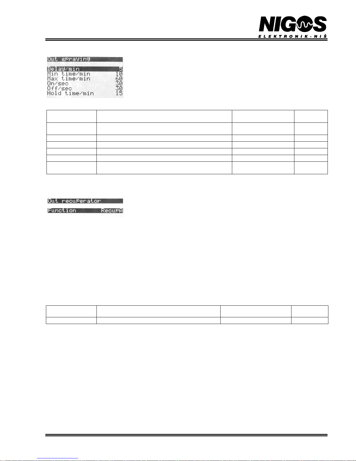
EQUIPMENT FOR MEASUREMENT&CONTROL AND DRYERS
B. Nikolica-Serjoze 12, 18000 Nis, Serbia; Phone/Fax:+38118 211-212, 217-468; [email protected]; www.nigos.rs
Automatic control unit MC-2000 (version 5.4.6) 21
3.9.3.2. Option: Out spraying
This option enables setting of parameters which define operation of spraying output. Table 3.9 shows
all parameters and their values.
Table 3.9. Parameters of Out spraying option
PARAMETER
LABEL
DESCRIPTION
RANGE OF
PARAMETER VALUES
DEFAULT
VALUE
Delay/min
Delays spraying for given time once conditions for spraying are
met
1 min to 240 min
5
Min time/min
Minimal time for spraying
1 min to 240 min
10
Max time/min
Maximal time for spraying in case the conditions are not met
1 min to 240 min
60
On/sec
Spraying on time
1 min to 240 min
30
Off/sec
Spraying off time
1 min to 240 min
30
Hold time/min
Holdback time (pause) after spraying during which it is
impossible to start it again
1 min to 240 min
15
3.9.3.3. Option: Out recuperator
This option control output for fans in recuperators or flaps behavior. These fans are turned on when
drying is required. Same output is used for compressor operation, so when compressor is attached (in
dehumidifying dryers) this option can not be used.
MC-2000 controller can operate both conventional and dehumidifying dryers. One same relay output is used for both types of dryers but it has
different functions depending on the type of dryer and installed equipment.
- In dehumidifying dryers, compressor is connected to this relay output, so user does not have any control over it. If this option is activated
(Function = fan, recupA or recupB) it will turn off compressor function. In such cases compressor will operate in same way as fans in
recuperator or flaps. Operation of this output can be monitored via digital input Di2 which is also sharable with compressor 3. LED diode on
front panel that show operation of compressor also shows operation of fan in recuperator or flaps. Blinking LED indicate pause time, while
constant lit LED signals active output.
- Default value for this parameter is no and it should be changed only if appropriate equipment is installed in conventional kilns. In some
conventional dryers additional (forced) air exchange is required. Then additional fan can be installed in standard or in servo flaps (dampers).
To enable control of these fans select the value fan. Some other conventional dryers can have recuperators installed (devices for heat loss
reduction and drying quality improvement). If recuperators are installed, user must select value recupA or recupB in this option to enable
their proper function.
Table 3.10. Parameters of Out recuperator option
PARAMETER
LABEL
DESCRIPTION
RANGE OF
PARAMETER VALUES
DEFAULT
VALUE
Function
Selection of the recuperator output function
no, fan, recupA, recupB
recupA
Operation description:
- When function recupA is selected then flaps are disabled. *select this option if kiln has only recuperators
- When function recupB is selected then flaps are opened in case that humidity is too high and additional ventilation is required. * select
this option if kiln has both recuperator and flaps
- When function fan is selected then fan in flaps is turned on (or recuperator if present). * select this option if kiln has fans in flaps
- When function no is selected then this output is disabled and drying is performed only via servo driven flaps or compressor. This option
can be used to test operation of flaps. * select this option if kiln does not have recuperators
In all cases it it possible to use flaps for additional cooling during cooling phase. It is commonly used to speed up cooling because
sometime chamber with recuperators can not cool down fast enough (due to high energy efficiency of recuperators).
Page 22
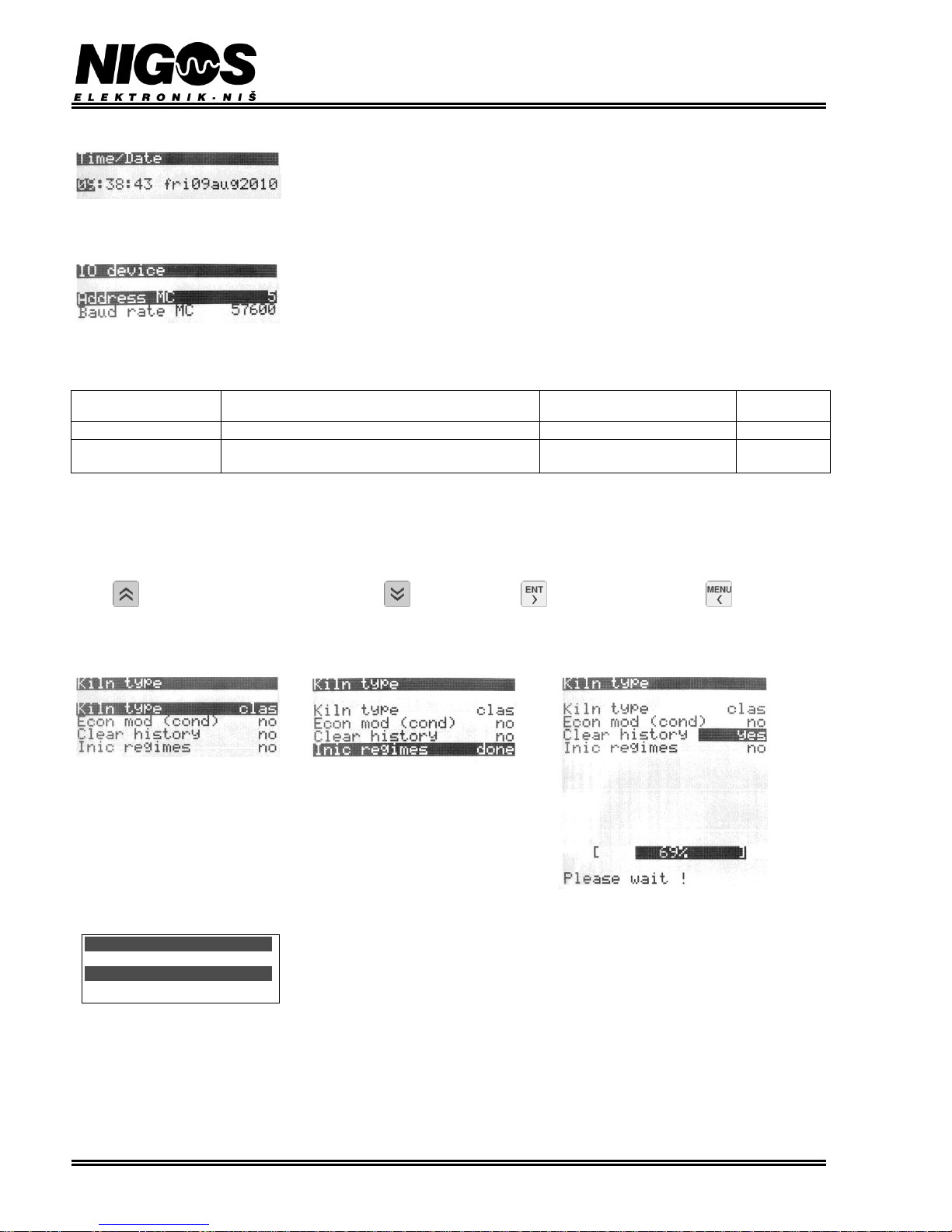
EQUIPMENT FOR MEASUREMENT&CONTROL AND DRYERS
B. Nikolica-Serjoze 12, 18000 Nis, Serbia; Phone/Fax:+38118 211-212, 217-468; [email protected]; www.nigos.rs
22 Automatic control unit MC-2000 (version 5.4.6)
3.9.3.4. Option: Time/date
Option Time/Date enables user to set real time clock. This clock has no automatic adjustment for
daylight saving changes. When needed, it must be manually adjusted to correct time.
3.9.3.5. Option: IO device
All parameters for communication with input and output devices are set from this option. Address is
unique device address in communication, baud rate is communication speed.
- Label MC corresponds to MC-2000 controller setting and it's communication with PC
Table 3.11 shows all parameters and their possible values.
Table 3.11. Parameters of IO device option
PARAMETER
LABEL
DESCRIPTION
RANGE OF
PARAMETER VALUES
DEFAULT
VALUE
Address MC
Unique device address in communication
1 to 95
1
Baud rate MC
Communication speed
4800, 9600, 14400, 19200,
28800, 57600, 115200
57600
3.9.4. Option: Kiln type
This option provides selection of kiln type (and controller operation mode), compressor operation, history record erasing and parameter
initialization.
Parameter Kiln type can be conventional (CONV) or dehumidifying (condensation) (COND). Other parameters have yes/no value.
Button sets currently selected value to "yes", button to "no". Use button to confirm action, and button to cancel the
action.
Any performed action is verified with message "done". "Clear history" action erases complete history record and can not be reversed.
History clearing can take a while, so indicator bar is showed during this process to inform the user of current progress.
3.9.5. Option: Oscillation drying
Oscillation drying is experimental way of drying which is developed by professor Goran Milic from
Forestry Faculty in Belgrade designed to speed up drying time and improve quality of dried timber.
User can adjust temperature and EMC deviation within selected regime.
Note: NIGOS-elektronik supports exploration of new drying technologies, but at this moment we lack information to support
successful use of this method. It is let to customer to use this option at his own decision. We recommend extra care when this option is
used! NIGOS-elektronik do not suggest use of this option while it is still in development phase! NIGOS-elektronik do not take any
responsibility for any damage or unwanted faults (bents, cracks, warps, etc.) which may occur on timber due to use of oscillation
drying.
Oscillation drying
Function no
Page 23
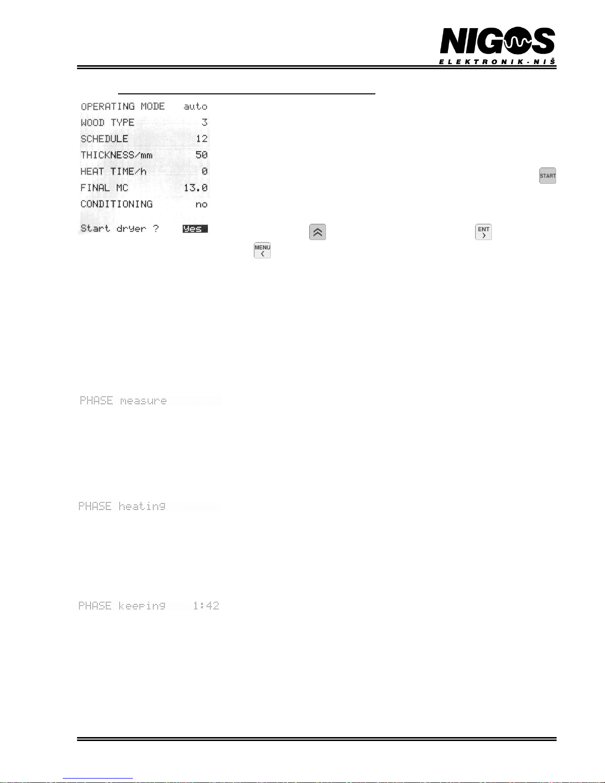
EQUIPMENT FOR MEASUREMENT&CONTROL AND DRYERS
B. Nikolica-Serjoze 12, 18000 Nis, Serbia; Phone/Fax:+38118 211-212, 217-468; [email protected]; www.nigos.rs
Automatic control unit MC-2000 (version 5.4.6) 23
4. OPERATING PRINCIPLES (DRYING PRINCIPLE)
At the start of each process it is required to set parameters relevant to that process. For conventional
drying user must set: MENU>Access>Access code (2000); MENU>Kiln type>conv.
For dehumidifying drying (when compressor is used), dehumidifying kiln must be selected:
MENU>Access>Access code (2000); MENU>Kiln type>cond). It is recommended to
select conventional drying when heat treatment (sterilization) is used. Once these settings are made,
they are saved in controller's memory until changed (even after power loss).
After these settings, Drying param option must be set. Each parameter can be changed during
drying process. After all parameters are set, process is started with a pressing on the button .
Selected parameters are then displayed and confirmation is required.
In case something must be changed, it can be done through MENU>Drying param. All
parameters are memorized for next drying cycle, except parameter HEAT TIME/h which is reset
after each drying cycle and should be set again if needed.
To start drying, use button to change the value to yes and then button to confirm selected
action. After this, selected process is started. Button cancels started action. When some process is active, LED indicator RUN will lit.
NOTES:
- If average wood MC is lower than FINAL MC, drying process will end immediately.
- If there is some alarm warning it makes no sense to start drying until it is resolved.
- When power failure occur, controller will memorize all data and continue drying upon power reconnection.
4.1. Drying
Drying is performed in several phases depending on the user selection. Possible phases are: measurement, heating, core heat, drying,
conditioning, cooling and end.
4.1.1. PHASE: measurement
Every process starts with this phase. Controller waits for some time for measurement stabilization. After measurement phase, controller will
automatically advance to appropriate phase depending on the received data. During this phase
LCD will display following message and LED indicator RUN will blink.
4.1.2. PHASE: heating
After completion of measuring phase, if the temperature inside kiln is lower than start temperature from drying regime heating phase starts.
Temperature increases by temperature ramp rate for heating phase for the chosen regime. Wood thickness also influence this parameter.
Temperature deviation does not pause this process.
EMC is set to value equal to first EMC value in selected regime increased by 2% and calculated according to selected wood thickness. EMC
can be manually set in this phase. Fan speed is set to first value in the regime. This value can also be set manually. Manually set values are
kept even after power loss.
This phase allows active heating, fans, drying, spraying and compressor outputs.
LCD shows phase label:
When set temperature reach first temperature in the regime, core heating phase will start if HEAT TIME/h is different than 0. If this
parameter equals 0, controller will advance to drying phase.
4.1.3. PHASE: core heating
During this phase, controller will keep (maintain) reached temperature and EMC after heating phase for the time set by user in parameter:
Drying param> HEAT TIME/h.
EMC and fan speed are also maintained, but can also be altered manually. All outputs can be activated.
LCD displays label keeping and remaining time:
If power loss occur during this phase, controller advance strait to this phase after measurement phase and continues in it for remaining time.
Page 24
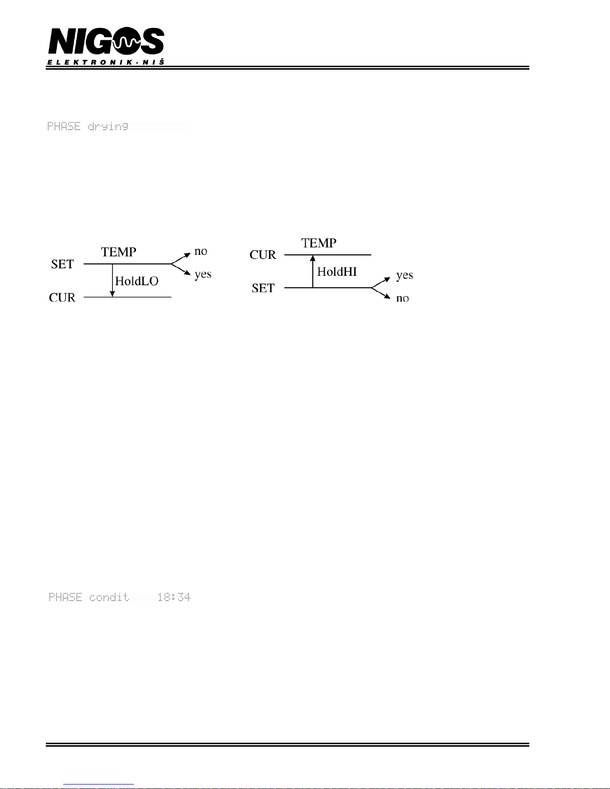
EQUIPMENT FOR MEASUREMENT&CONTROL AND DRYERS
B. Nikolica-Serjoze 12, 18000 Nis, Serbia; Phone/Fax:+38118 211-212, 217-468; [email protected]; www.nigos.rs
24 Automatic control unit MC-2000 (version 5.4.6)
4.1.4. PHASE: drying
In this phase controller starts to follow selected drying regime. This phase lasts until average wood MC drop to the value set in parameter
Drying param> FINAL MC.
LCD displays following:
Set values will change according to time increase ratio (gradient) defined in SETUP>System>DryTempRampRate. Thickness influence
the value of this parameter (thickness to heat ramp rate). When new values are required, according to average wood MC and chosen regime,
controller will determine required temperature, EMC and fan speed.
NOTE: For dehumidifying dryer: If the temperature in the chamber is higher than 38°C, and EMC is higher than SET EMC by 1%, controller
will not allow further increase of the temperature.
When HI temperature deviation warnings occur (SET Temp is lower than current) controller will stop temperature decreasing. When LO
temperature deviation warnings occur (LO Temp is higher than current) controller will stop temperature increasing.
Parameter for wood thickness influence speed of drying, so by altering the parameter Drying param>THICKNESS/mm it is possible to
speed up, or slow down drying. Reducing the thickness evoke lowering of EMC and thus speeding up of drying process. Vice versa, increasing
the thickness evoke raising of EMC and thus slowing down of drying process.
Fan speed is always related to average wood MC. When manual fan speed setting is enabled Fans>Enable set spee = yes, than user
data will be used. Fan speed can be set manually at any stage of the drying process.
Maximum value for fan speed is 100%, EMC can be up to 30.0%, and temperature is limited by parameter SETUP>System>Max temp/°.
User regime can be made with even higher temperature, but this parameter will cut the temperature curve to maximum value given by this
parameter.
When average wood MC drops to a value given by user in parameter Drying param>FINAL MC, controller will consider drying phase
complete. If conditioning phase is enabled (parameter Drying param>CONDITIONING = yes), controller will advance to conditioning
phase, and if conditioning is disabled - to cooling phase.
4.1.5. PHASE: equalization
This phase is intended for the equalization of the moisture between the wood of all the probes for measuring the moisture content of wood. If
any of the probes to measure low humidity - which means that the tree is dry to limit moisture - automat moves to phase equalization to invest
in other probes dropped on that gramičnu value. After equalization, the process returns to the drying phase.
Phase equalization is possible only if the final moisture is set to less than 10% MC.
During the drying process it is possible this phase turned on or off at any time. We recommend using this phase in cases where it is required
the best possible quality of dried material.
This function can significantly extend drying time and successful ending depends on the ability of wood dryer to provide desired
conditions!
4.1.6. PHASE: conditioning
This phase, as the last phase of drying process, provides equalization of wood moisture content
inside the wood and on the wood surface. Flaps (dampers) will close. Controller will allow
activity of heating, fans and spraying outputs, and block activity of cooling and compressor outputs. Duration of the conditioning phase is
defined by time parameter in selected regime, but it is recalculated depending on selected thickness. If the lumber thickness is less than 50mm,
conditioning phase lasts a bit shorter than it is specified by regime, and vice versa, if the thickness is greater than 50mm, the phase lasts a bit
longer. Remaining time is displayed on LCD.
Set temperature and EMC are given in regime and can not be changed. Fan speed is also given in regime, but can be manually altered.
After power loss and reconnection, this phase will continue for remaining time in the moment of power loss. Next phase is cooling phase.
Page 25

EQUIPMENT FOR MEASUREMENT&CONTROL AND DRYERS
B. Nikolica-Serjoze 12, 18000 Nis, Serbia; Phone/Fax:+38118 211-212, 217-468; [email protected]; www.nigos.rs
Automatic control unit MC-2000 (version 5.4.6) 25
4.1.7. PHASE: cooling
During cooling phase, only fans output can be activated. Valves and flaps are shut. Set
temperature is equal to last given temperature decreased for value of parameter
SETUP>System>Temp END/°. EMC and fan speed will remain at same value as in last phase before cooling. LCD displays elapsed time.
After power loss and reconnection, this phase will continue until set temperature is reached. Once the temperature drops to required value,
drying has ended.
4.1.8. PHASE: end
Fans are stopped, and valves and flaps shut. Controller shuts down all outputs. Message -end is displayed at the bottom of the LCD.
4.1.9. PHASE: pause
Pausing drying process.
4.2. SETPOINT DEVIATION
Whenever some process is active, controller will compare deviation (difference) between measured and set points. Allowed deviations are
given in percent values. If actual value is higher than set value for given deviation percentage, HI deviation will be reported. Vice versa, if the
actual value is lower than set value for given deviation percentage, LO deviation will be reported.
HI Temperature deviation warning will stop increase of temperature in automatic mode. LO temperature deviation will cause flaps to shut. In
semi-automatic mode, these warnings are only informational. EMC deviation is only informational.
4.3. POWER FAILURE DURING DRYING PROCESS
If power is lost and then restored, while the drying process is running in automatic mode, MC-2000 performs measuring of wood moisture
content, calculates average MC and then determines temperature and EMC setpoints. After that, the unit determines proper point for resuming
the process, and continues it. In semiautomatic mode, after restoring power, all parameters, including setpoints for temperature and EMC will
be restored to their power-down values and process will be continued from where it was interrupted when power was lost.
Page 26
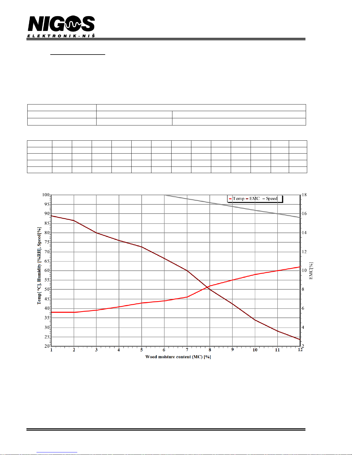
EQUIPMENT FOR MEASUREMENT&CONTROL AND DRYERS
B. Nikolica-Serjoze 12, 18000 Nis, Serbia; Phone/Fax:+38118 211-212, 217-468; [email protected]; www.nigos.rs
26 Automatic control unit MC-2000 (version 5.4.6)
5. DRYING REGIME
As mentioned in chapter 1, automatic control unit MC-2000 has 60 drying regimes, all are factory pre-defined but user can change any of them
according to his own needs. Here is given an example of how drying regime should be defined. On the next page, there is a blank table which
user can copy and make regimes on his own.
NOTE: Minimal drying temperature MUST BE LOWER than the first temperature value in the selected regime. Other ways, the drying will
not start. It is recommended that it is set to be 5 10 C lower than the first temperature value in the regime (in this example minimal drying
temperature is set to 33 °C, and the first value for temperature in the regime is 39 °C).
Regime number:
18
Heating temperature ramp rate:
5.0
°C / h
Regime type:
MC
Segment
1 2 3 4 5 6 7 8 9
10
11
12
Kond
MC
60
50
40
35
30
27
24
20
16
12 9 6
25 T 38.0
38.0
39.0
41.0
43.0
44.0
46.0
52.0
55.0
58.0
60.0
62.0
57.0
EMC
15.8
15.0
14.0
13.2
12.5
11.3
10.0
8.0
6.5
4.8
3.6
2.7
9.0
FAN
100.0
100.0
100.0
100.0
100.0
100.0
98.0
96.0
94.0
92.0
90.0
88.0
100.0
Page 27
EQUIPMENT FOR MEASUREMENT&CONTROL AND DRYERS
B. Nikolica-Serjoze 12, 18000 Nis, Serbia; Phone/Fax:+38118 211-212, 217-468; [email protected]; www.nigos.rs
Automatic control unit MC-2000 (version 5.4.6) 27
5.1. USER’S DRYING REGIME
Regime number:
Heating temperature ramp rate:
°C / h
Regime type:
Segment
1 2 3 4 5 6 7 8 9
10
11
12
Kond
MC
T
EMC
FAN
Page 28
EQUIPMENT FOR MEASUREMENT&CONTROL AND DRYERS
B. Nikolica-Serjoze 12, 18000 Nis, Serbia; Phone/Fax:+38118 211-212, 217-468; [email protected]; www.nigos.rs
28 Automatic control unit MC-2000 (version 5.4.6)
5.2. TABLE OF PREDEFINED DRYING REGIMES
DRYING
CONDITIONING
No
TEMP
EMC
Type
Heat
ramp
(°C/h)
Temp
EMC
Temp
EMC
Temp
EMC
Time
(h)
Temp
(°C)
EMC
(%)
60% MC
30% MC
9% MC
CONVENTIONAL DRYING SCHEDULES
1
01
01
MC
2.5
28,0
21,0
30,0
16,8
48,0
5,0
40
46.0
9.0 2 01
02
MC
3.0
28,0
20,0
30,0
15,5
48,0
4,5
35
46.0
9.0 3 01
03
MC
3.5
28,0
19,0
30,0
14,5
48,0
4,5
30
46.0
9.0 4 01
04
MC
4.0
28,0
17,5
30,0
13,5
48,0
4,0
30
46.0
9.0 5 01
05
MC
5.0
28,0
17,0
30,0
12,5
48,0
3,8
25
46.0
9.0 6 02
02
MC
3.0
32,0
20,0
34,0
15,5
55,0
4,5
35
52.0
9.0 7 02
03
MC
3.5
32,0
19,0
34,0
14,5
55,0
4,5
30
52.0
9.0
8
02
04
MC
4.0
32,0
17,5
34,0
13,5
55,0
4,0
30
52.0
9.0
9
02
05
MC
5.0
32,0
17,0
34,0
12,5
55,0
3,8
25
52.0
9.0
10
02
06
MC
7.0
32,0
15,0
34,0
11,2
55,0
3,8
25
52.0
9.0
11
03
03
MC
3.5
35,0
19,0
38,0
14,5
58,0
4,5
30
55.0
9.0
12
03
04
MC
4.0
35,0
17,5
38,0
13,5
58,0
4,0
30
55.0
9.0
13
03
05
MC
5.0
35,0
17,0
38,0
12,5
58,0
3,8
25
55.0
9.0
14
03
06
MC
7.0
35,0
15,0
38,0
11,2
58,0
3,8
25
55.0
9.0
15
03
07
MC
8.0
35,0
14,0
38,0
10,0
58,0
3,5
20
55.0
9.0
16
04
03
MC
3.5
38,0
19,0
40,0
14,5
60,0
4,5
30
57.0
9.0
17
04
04
MC
4.0
38,0
17,5
40,0
13,5
60,0
4,0
30
57.0
9.0
18
04
05
MC
5.0
38,0
17,0
40,0
12,5
60,0
3,8
25
57.0
9.0
19
04
06
MC
7.0
38,0
15,0
40,0
11,2
60,0
3,8
25
57.0
9.0
20
04
07
MC
8.0
38,0
14,0
40,0
10,0
60,0
3,5
20
57.0
9.0
21
05
04
MC
4.0
42,0
17,5
44,0
13,5
62,0
4,0
30
60.0
9.0
22
05
05
MC
5.0
42,0
17,0
44,0
12,5
62,0
3,8
25
60.0
9.0
23
05
06
MC
7.0
42,0
15,0
44,0
11,2
62,0
3,8
25
60.0
9.0
24
05
07
MC
8.0
42,0
14,0
44,0
10,0
62,0
3,5
20
60.0
9.0
25
05
08
MC
9.0
42,0
13,0
44,0
9,2
62,0
3,4
15
60.0
9.0
26
06
04
MC
4.0
46,0
17,5
48,0
13,5
64,0
4,0
30
62.0
9.0
27
06
05
MC
5.0
46,0
17,0
48,0
12,5
64,0
3,8
25
62.0
9.0
28
06
06
MC
7.0
46,0
15,0
48,0
11,2
64,0
3,8
25
62.0
9.0
29
06
07
MC
8.0
46,0
14,0
48,0
10,0
64,0
3,5
20
62.0
9.0
30
06
08
MC
9.0
46,0
13,0
48,0
9,2
64,0
3,4
15
62.0
9.0
31
07
05
MC
5.0
50,0
17,0
52,0
12,5
69,0
3,8
25
65.0
9.0
32
07
06
MC
7.0
50,0
15,0
52,0
11,2
69,0
3,8
25
65.0
9.0
33
07
07
MC
8.0
50,0
14,0
52,0
10,0
69,0
3,5
20
65.0
9.0
34
07
08
MC
9.0
50,0
13,0
52,0
9,2
69,0
3,4
15
65.0
9.0
35
07
09
MC
10.0
50,0
12,0
52,0
8,5
69,0
3,0
10
65.0
9.0
36
08
05
MC
5.0
55,0
17,0
55,0
12,5
72,0
3,8
25
68.0
9.0
37
08
07
MC
8.0
55,0
14,0
55,0
10,0
72,0
3,5
20
68.0
9.0
38
08
09
MC
10.0
55,0
12,0
55,0
8,5
72,0
3,0
10
68.0
9.0
39
13
07
MC
8.0
55,0
14,0
60,0
10,0
80,0
3,5
20
75.0
9.0
40
14
08
MC
9.0
65,0
13,0
70,0
9,2
85,0
3,4
15
80.0
9.0
Note: In heating phase EMC is 2% higher than starting EMC in drying phase.
Page 29
EQUIPMENT FOR MEASUREMENT&CONTROL AND DRYERS
B. Nikolica-Serjoze 12, 18000 Nis, Serbia; Phone/Fax:+38118 211-212, 217-468; [email protected]; www.nigos.rs
Automatic control unit MC-2000 (version 5.4.6) 29
DEDACATED REGIMES
Note: In heating phase EMC is 2% higher than starting EMC in drying phase.
Drying
Conditioning
No.
TEMP
EMC
Type
Heat
ramp
(°C/h)
Temp
EMC
Temp
EMC
Temp
EMC
Time
(h)
Temp
(°C)
EMC
(%)
60% MC
30% MC
9% MC
CONVENTIONAL
SCHEDULES
softwood
41
03
12
MC
7.0
35,0
18,0
38,0
14,0
58,0
4,0
30
55,0
9,0
42
05
05
MC
5.0
42,0
17,0
44,0
12,5
62,0
3,8
25
60,0
9,0
43
06
11
MC
7.0
46,0
16,0
48,0
11,0
64,0
3,5
20
62,0
9,0
beech
44
12
12
MC
7.0
38,0
18,0
38,0
14,0
57,0
4,0
30
55,0
9,0
45
12
04
MC
4.0
38,0
17,5
38,0
13,5
57,0
4,0
30
55,0
9,0
46
04
05
MC
5.0
38,0
17,0
40,0
12,5
60,0
3,8
25
57,0
9,0
oak
47
09
02
MC
3.0
28,0
20,0
30,0
15,5
58,0
4,5
35
55,0
9,0
48
09
03
MC
3.5
28,0
19,0
30,0
14,5
58,0
4,5
30
55,0
9,0
49
09
10
MC
7.0
28,0
17,5
30,0
13,0
58,0
4,0
35
55,0
9,0
lamella
<10mm
50
10
12
MC
7.0
25,0
18,0
32,0
14,0
46,0
4,0
30
44,0
9,0
DEHUMIDIFYING
SCHEDULES
plank
very
slow
51
15
02
MC
3.0
36,0
20,0
40,0
15,5
56,0
4,5
35
50,0
9,0
slow
52
15
03
MC
3.5
36,0
19,0
40,0
14,5
56,0
4,5
30
50,0
9,0
average
53
15
04
MC
4.0
36,0
17,5
40,0
13,5
56,0
4,0
30
50,0
9,0
fast
54
15
05
MC
5.0
36,0
17,0
40,0
12,5
56,0
3,8
25
50,0
9,0
very
fast
55
15
06
MC
7.0
36,0
15,0
40,0
11,2
56,0
3,8
25
50,0
9,0
lamella
<10mm
56
11
02
MC
3.0
35,0
20,0
36,0
15,5
46,0
4,5
35
44,0
9,0
57
11
03
MC
3.5
35,0
19,0
36,0
14,5
46,0
4,5
30
44,0
9,0
58
11
13
EMC
TIMED
SCHEDULES
59
10
10
Time
(h)
60
10
12
Time
(min)
Page 30

EQUIPMENT FOR MEASUREMENT&CONTROL AND DRYERS
B. Nikolica-Serjoze 12, 18000 Nis, Serbia; Phone/Fax:+38118 211-212, 217-468; [email protected]; www.nigos.rs
30 Automatic control unit MC-2000 (version 5.4.6)
TABLE OF CONTENTS:
1. MC-2000 MAIN CHARACTERISTICS .............................................................................................................................................................................. 1
2. INSTALLATION .................................................................................................................................................................................................................. 2
2.1. CONNECTING DIAGRAM ......................................................................................................................................................................................... 2
2.2. MC -2000 CONNECTION ............................................................................................................................................................................................ 3
2.3. MC -2000, MKM-08 AND DS-04t INTERCONNECTION .......................................................................................................................................... 4
2.4. CONNECTION OF TEMPERATURE, EMC AND 8-POINTS MC MEASUREMENT SET ..................................................................................... 5
3. OPERATION ......................................................................................................................................................................................................................... 6
3.1. MC -2000 FRONT PANEL LAYOUT .......................................................................................................................................................................... 6
3.1.1. LCD display functions ........................................................................................................................................................................................ 6
3.1.2. Temperature, EMC and wood MC display ......................................................................................................................................................... 7
3.1.3. Buttons function ................................................................................................................................................................................................. 7
3.2. "RELAY OUTPUTS" FRONT PANEL SECTION ...................................................................................................................................................... 8
3.2.1. Buttons function ................................................................................................................................................................................................. 8
3.2.2. Signaling LED diodes ......................................................................................................................................................................................... 9
3.3. PARAMETER SETTINGS ........................................................................................................................................................................................... 9
3.3.1. Option: Drying parameters .............................................................................................................................................................................. 10
3.3.1.1. Parameter: OPERATING MODE ............................................................................................................................................................ 10
3.3.1.2. Parameter: TIMBER GROUP .................................................................................................................................................................. 10
3.3.1.3. Parameter: SCHEDULE .......................................................................................................................................................................... 10
3.3.1.4. Parameter: THICKNESS/mm .................................................................................................................................................................. 11
3.3.1.5. Parameter: HEAT TIME/h ....................................................................................................................................................................... 12
3.3.1.6. Parameter: FINAL MC ............................................................................................................................................................................ 12
3.3.1.7. Parameter: EQUALIZATION.................................................................................................................................................................. 12
3.3.1.8. Parameter: CONDITIONING .................................................................................................................................................................. 12
3.3.2. Option: Probes MC ................................................................................................ ................................................................ ......................... 12
3.3.3. Option: Control ............................................................................................................................................................................................... 13
3.3.4. Option: History ............................................................................................................................................................................................... 13
3.3.5. Option: Statistics............................................................................................................................................................................................. 13
3.3.6. Option: SETUP ............................................................................................................................................................................................... 14
3.3.6.1. Option: SETUP > Compressor ................................................................................................................................................................. 14
3.3.6.2. Option: SETUP > Fans ................................................................................................ ................................................................ ............ 14
3.3.7. Option: Kiln type ............................................................................................................................................................................................ 14
3.3.8. Option: Access ................................................................................................................................................................................................ 14
3.4. OPERATING MODES ............................................................................................................................................................................................... 15
3.4.1. Automatic, semiautomatic and manual mode ................................................................................................................................................... 15
3.4.1.1. Automatic mode ........................................................................................................................................................................................ 15
3.4.1.2. Semiautomatic mode ................................................................................................................................................................................. 15
3.4.1.3. Changing of operating mode (auto to semiauto and vice versa) ................................................................................................................. 15
3.4.1.4. Manual mode ............................................................................................................................................................................................. 15
3.5. DRYING PROCESS START UP ............................................................................................................................................................................... 16
3.6. STOPPING DRYING PROCESS ............................................................................................................................................................................... 16
3.7. PAUSING DRYING PROCESS ................................................................................................................................................................................. 16
3.8. WARNINGS AND ALARM SITUATIONS .............................................................................................................................................................. 16
3.9. ADDITIONAL ADJUSTMENTS ............................................................................................................................................................................... 18
3.9.1. Option: Access ................................................................................................................................................................................................ 18
3.9.2. Option: REGIMES.......................................................................................................................................................................................... 19
3.9.3. Option: SETUP ............................................................................................................................................................................................... 20
3.9.3.1. Option: System ........................................................................................................................................................................................ 20
3.9.3.2. Option: Out spraying ............................................................................................................................................................................... 21
3.9.3.3. Option: Out recuperator ........................................................................................................................................................................... 21
3.9.3.4. Option: Time/date .................................................................................................................................................................................... 22
3.9.3.5. Option: IO device .................................................................................................................................................................................... 22
3.9.4. Option: Kiln type ............................................................................................................................................................................................ 22
3.9.5. Option: Oscillation drying .............................................................................................................................................................................. 22
4. OPERATING PRINCIPLES (DRYING PRINCIPLE) .................................................................................................................................................... 23
4.1. Drying ......................................................................................................................................................................................................................... 23
4.1.1. PHASE: measurement ...................................................................................................................................................................................... 23
4.1.2. PHASE: heating ................................................................................................................................................................................................ 23
4.1.3. PHASE: core heating ........................................................................................................................................................................................ 23
4.1.4. PHASE: drying ................................................................................................................................................................ ................................. 24
4.1.5. PHASE: equalization ................................ ................................................................ ................................................................ ........................ 24
4.1.6. PHASE: conditioning ....................................................................................................................................................................................... 24
4.1.7. PHASE: cooling ............................................................................................................................................................................................... 25
4.1.8. PHASE: end ..................................................................................................................................................................................................... 25
4.1.9. PHASE: pause .................................................................................................................................................................................................. 25
4.2. SETPOINT DEVIATION ........................................................................................................................................................................................... 25
4.3. POWER FAILURE DURING DRYING PROCESS .................................................................................................................................................. 25
5. DRYING REGIME ............................................................................................................................................................................................................. 26
5.1. USER’S DRYING REGIME ...................................................................................................................................................................................... 27
5.2. TABLE OF PREDEFINED DRYING REGIMES ...................................................................................................................................................... 28
 Loading...