

Page 1
PRO Series 8CH
Elite Series 8CH
Page 2

Contents
2
Chapter 1: FCC Radiation Norm ............................................................ 6
Chapter 2: Package Contents ................................................................ 7
Chapter 3: System Requirements .......................................................... 8
Chapter 4: Safety Instructions ................................................................ 9
Chapter 5: Troubleshooting .................................................................. 11
Chapter 6: DVR Components ............................................................... 13
6.1 Back Panel of DVR ................................................................ 13
6.2 Front Panel of DVR ................................................................ 14
6.3 Mouse .................................................................................... 15
6.4 Remote ................................................................................... 16
Chapter 7: DVR Installation .................................................................. 17
7.1 Connecting the Power Supply ................................................ 17
7.2 Connecting the DVR to a TV or Monitor ................................. 18
Chapter 8: Camera Installation ............................................................. 19
8.1 Connecting Cameras to the DVR ........................................... 19
8.2 Mounting the Cameras ........................................................... 20
Chapter 9: DVR Start-up ...................................................................... 21
9.1 System Initialization ................................................................ 21
9.2 On-Screen Display ................................................................. 22
Chapter 10: Startup Wizard .................................................................. 23
Chapter 11: Login Screen ..................................................................... 24
Chapter 12: Main Menu ........................................................................ 25
Chapter 13: Menu Icons ....................................................................... 26
Chapter 14: Basic Menu ....................................................................... 27
14.1 System Menu ....................................................................... 28
14.2 Date/Time Menu ................................................................... 29
Page 3

Contents
3
14.2.1 Date/Time Menu ....................................................... 29
14.2.2 DST Menu ................................................................. 30
14.3 Display Menu ....................................................................... 31
14.3.1 Display Menu ............................................................ 31
14.3.1.1 Mask Screen .................................................. 32
14.3.1.2 Color Screen .................................................. 33
14.3.1.3 Time/Name Screen ........................................ 34
14.3.2 Auto Seq Menu ......................................................... 35
14.4 Record Menu ........................................................................ 36
14.4.1 Basic Menu ............................................................... 36
14.4.2 Bit Rate Menu ........................................................... 37
14.4.3 Resolution ................................................................. 38
14.4.4 Schedule Menu ......................................................... 39
14.5 User Menu ............................................................................ 40
14.5.1 User Management Menu .......................................... 41
Chapter 15: Advanced Menu ................................................................ 43
15.1 Alarm Menu .......................................................................... 44
15.1.1 Motion Menu ............................................................. 44
15.1.1.1 Area Screen ................................................... 45
15.1.1.2 Schedule Screen ........................................... 46
15.1.1.3 Trigger Screen ............................................... 47
15.1.2 Video Loss Menu ...................................................... 48
15.1.3 Others Menu ............................................................. 49
15.1.4 Others Menu Continued ............................................ 50
15.2 Network Menu ...................................................................... 51
15.2.1 LAN Menu ................................................................. 51
15.2.2 PPPoE Menu ............................................................ 52
Page 4

Contents
4
15.2.3 Port Menu ................................................................. 53
15.2.4 Sub-Stream Menu ..................................................... 54
15.3 COMM Menu ........................................................................ 55
15.3.1 DDNS Menu .............................................................. 55
15.3.2 E-Mail Menu .............................................................. 56
15.3.3 UPnP Menu ............................................................... 57
15.4 PTZ Menu ............................................................................ 58
Chapter 16: Record Search Menu ........................................................ 59
Chapter 17: Converting Files to AVI ..................................................... 63
Chapter 18: Disk Management Menu ................................................... 64
Chapter 19: Information Menu .............................................................. 66
19.1 Device Menu ........................................................................ 67
19.2 Network Menu ...................................................................... 68
Chapter 20: Maintenance Menu ........................................................... 72
Chapter 21: Remote Access ................................................................. 76
Chapter 22: Port Forwarding ................................................................ 85
19.2.1 LAN Menu ................................................................. 68
19.2.2 PPPoE Menu ............................................................ 69
19.3 Online Menu ......................................................................... 70
19.4 Record Menu ........................................................................ 71
20.1 Basic Menu .......................................................................... 73
20.1.1 Firmware Upgrade .................................................... 74
20.2 Settings Menu ...................................................................... 75
21.1 Connection of DVR and Router/Modem ............................... 77
21.2 Windows Network Configuration .......................................... 78
21.3 Apple (Mac) Network Configuration ..................................... 81
22.1 C
hecking the Ports after Port Forwarding ............................ 85
Page 5

Contents
5
Chapter 23: DDNS Registration ........................................................... 86
23.1 Registering a Free Domain Name ........................................ 86
23.2 Adding your New Domain Name to your DVR ...................... 88
Chapter 24: Internet Viewing ................................................................ 89
24.1 Setting ActiveX Controls ....................................................... 89
24.2 DVR Login ............................................................................ 90
24.3 Using Nightowl View ............................................................ 91
24.4 Using Control Management Software (CMS-Nightowl View) 98
Chapter 25: Night Owl Pro Mobile Application .................................... 112
Chapter 26: Specifications of DVR ................................
Chapter 27: Information Log ............................................................... 120
Chapter 28: Warranty ......................................................................... 121
Interactive How-To videos are available for the
chapters indicated with this icon.
You can also visit Night Owl’s website at
http://www.nightowlsp.com/Videos
..................... 119
Page 6

6
Chapter 1: FCC Radiation Norm
FCC
This equipment has been tested and found to comply with limits for Class B
digital devices pursuant to Part 15 of Federal Communications Commission
(FCC) rules.
FCC Compliance Statement
These limits are designed to provide reasonable protection against
frequency interference in residential installation. This equipment generates,
uses, and can radiate radio frequency energy, and if not installed or used in
accordance with the instructions, may cause harmful interference to radio
communication. However, there is no guarantee that interference will not
occur in television reception, which can be determined by turning the
equipment off and on. The user is encouraged to try and correct the
interference by one or more of the following measures:
! Reorient or relocate the receiving antenna
! Increase the separation between the equipment and the receiver
! Connect the equipment into an outlet on a circuit different from that to
which the receiver is connected.
CAUTION!
The Federal Communications Commission warns the user that changes or
modifications to the unit not expressly approved by the party responsible for
compliance could void the user’s authority to operate the equipment.
Page 7
Contents
7
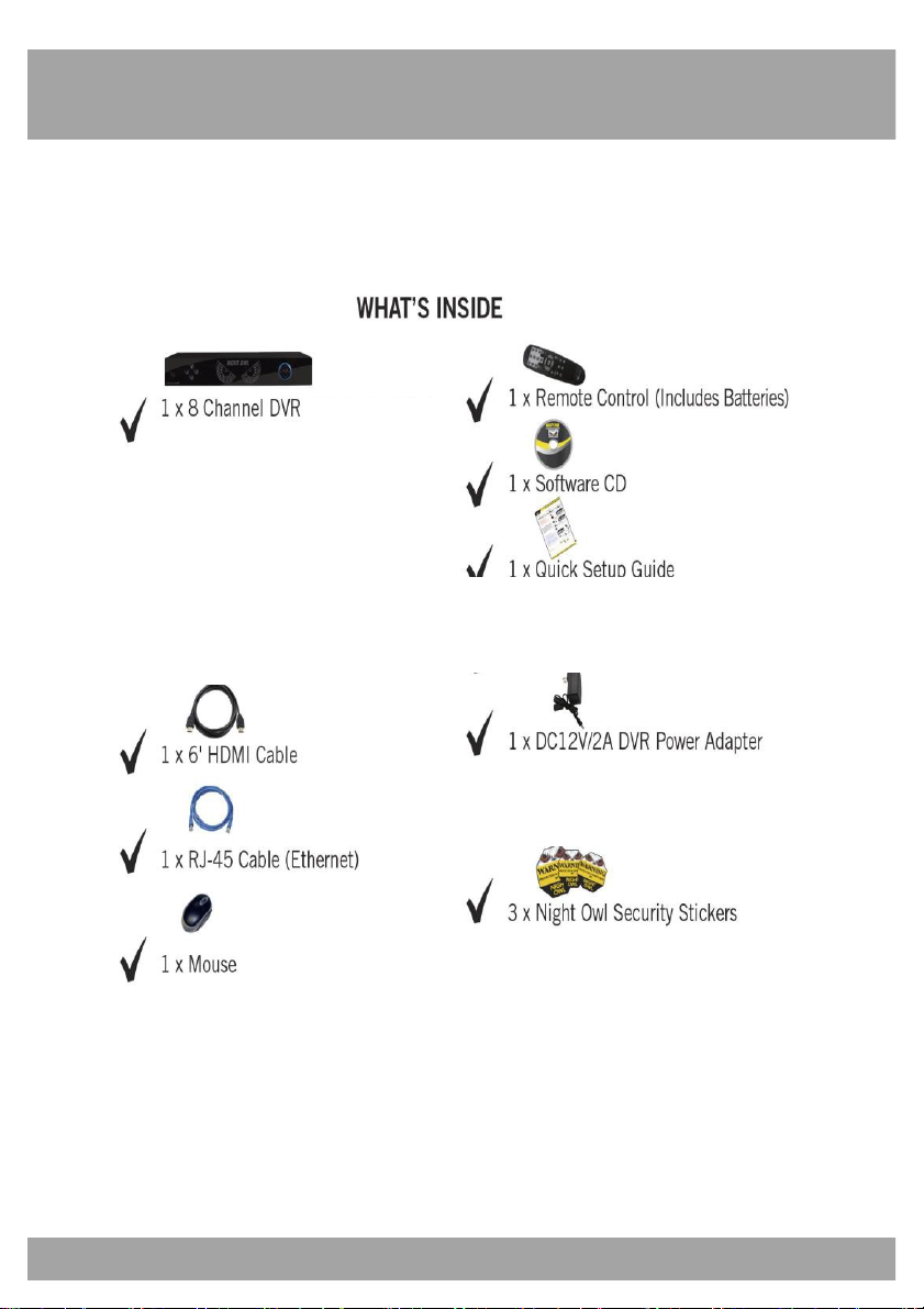
Chapter 2: Package Contents
Your DVR Security Kit includes the following items.
Page 8

8
Chapter 3: System Requirements
Please be sure the computer that you will use with the DVR Security Kit
complies with the following specifications:
• Windows® XP,VISTA, 7, or 8
• Mac® OS 10.6 and above
• Internet Explorer 7, 8, 9 or 10 web browser
• Includes CD-ROM drive
Page 9

Contents
9
Chapter 4: DVR Safety Instructions
• Use the provided power adapter.
Do not use this product with a power source that applies more than the
specified voltage.
• Never insert metal into the DVR case or its openings.
Inserting metal into the DVR case may cause electric shock.
• Do not operate in wet or dusty area.
Avoid placing the DVR in areas such as a damp basement or dusty
attic.
• Do not expose the DVR to rain or use near water.
If the DVR accidentally gets wet, unplug it and contact technical
support immediately.
• Keep product surfaces clean and dry.
To clean the outside case of the DVR, use a lightly dampened cloth.
Do not use cleaning solutions or solvents.
• Do not install near any heat sources.
Do not install the DVR near any heat sources such as stoves, heat
registers, radiators, or electronics (including amplifiers) that produce
heat.
• Unplug the DVR when moving it.
Make sure that the DVR is unplugged before you move it. When
moving this device, be sure to handle it with care.
• Make sure there is good air circulation around the DVR.
This DVR uses an internal hard drive, which generates heat during
operation, for video storage. Do not block vents on the DVR, as these
vents reduce the generated heat while the system is running. Place this
product in a well-ventilated area.
Page 10

10
Chapter 4: DVR Safety Instructions
• Do not attempt to remove the top cover.
If you observe any abnormal operation, unplug the DVR immediately
and contact technical support. Do not attempt to open the DVR to
diagnose the cause of the problem. (WARNING: You may be subjected
to severe electrical shock if you remove the cover of the DVR.)
• Handle the DVR carefully.
If you drop the DVR on any hard surface, it may damage the device. If
the DVR doesn’t work properly due to physical damage, contact an
authorized dealer for repair.
• Recommended: Use with an uninterruptable power supply (UPS).
Connecting your DVR and cameras to a UPS allows continuous
operation even during power outages. The run-time duration will
depend on the rating of the UPS used.
Page 11
11
Chapter 5: Troubleshooting
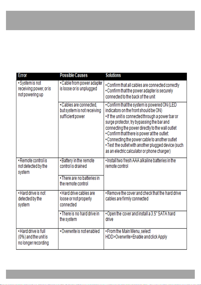
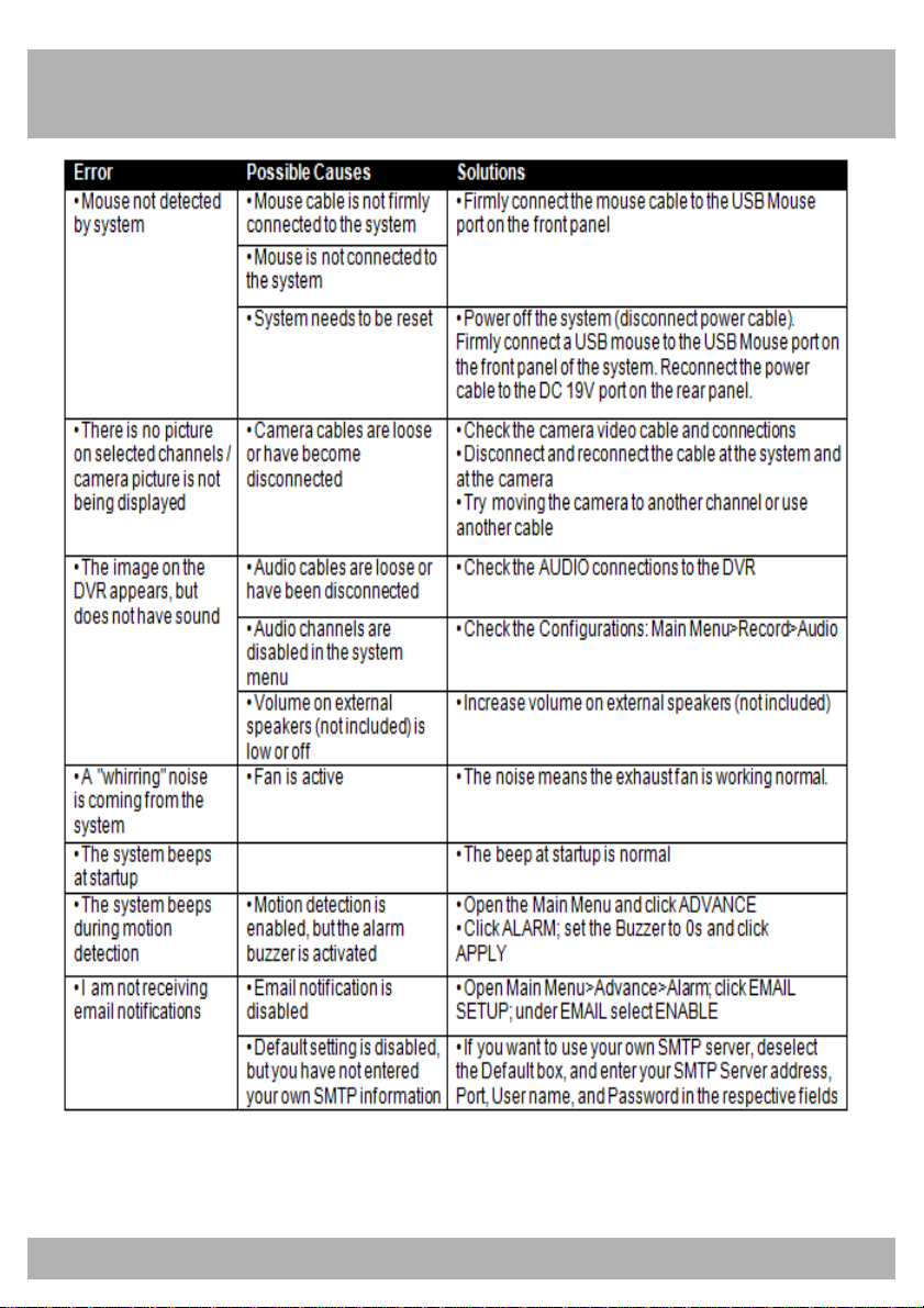
If a problem occurs, you may be able to easily correct it yourself. The
following table describes the most common problems and their solutions.
Please refer to the table before calling Night Owl Technical Support.
Page 12
Chapter 5: Troubleshooting
12
Page 13
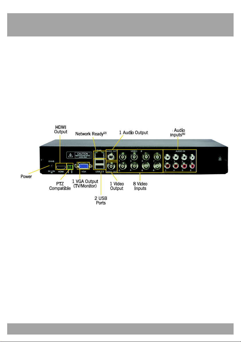
13
Chapter 6: DVR Components
6.1 Back Panel of DVR
Page 14
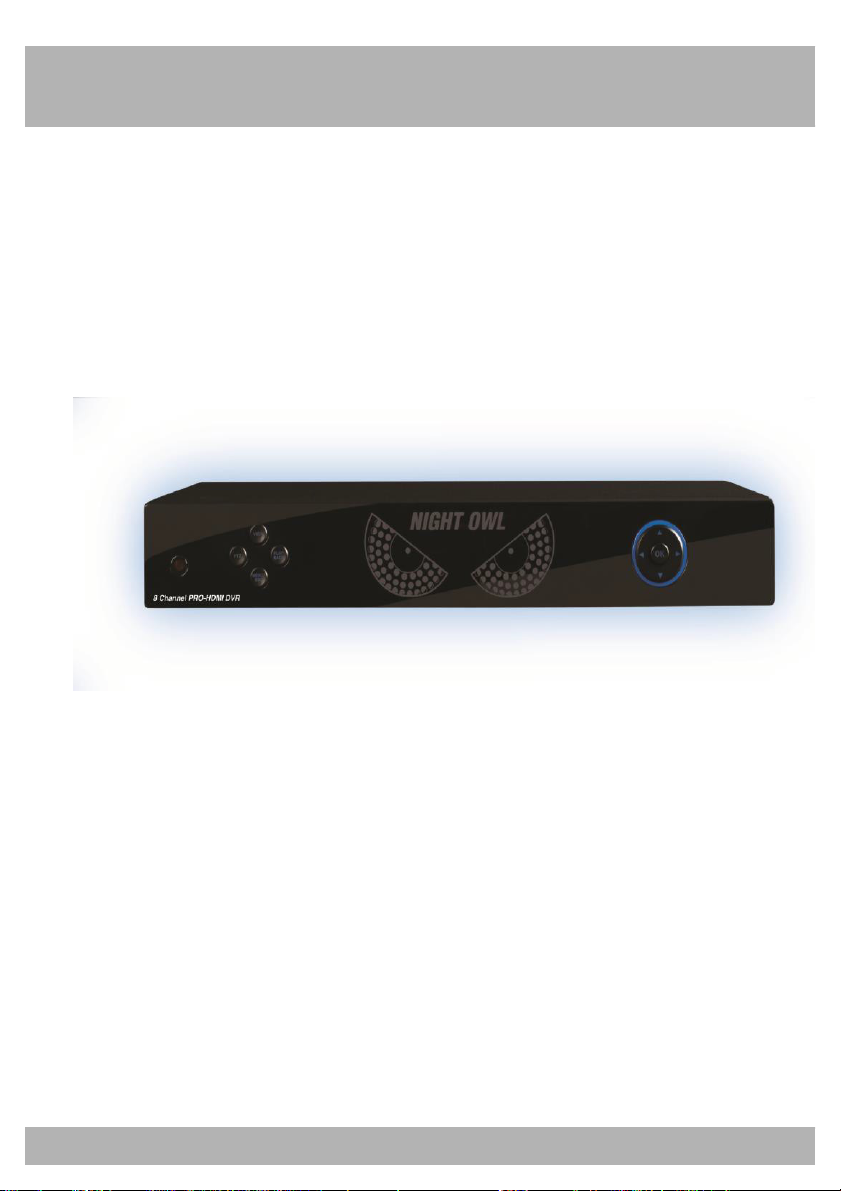
Chapter 6: DVR Components
6.2 Front Panel of DVR
14
Page 15
15
Chapter 6: DVR Components
6.3 Mouse
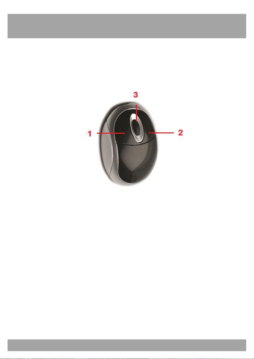
You can use a mouse instead of the remote control to navigate through
your DVR’s menus. Connect the included mouse to the USB port on the
back of the DVR.
Use the mouse buttons to perform the following:
1. Left Button: Click to select a menu option. During live viewing in
split-screen view, double-click on a channel to see the selected
channel in full-screen view; double-click the channel again to return
to split-screen view.
2. Right Button: Click to display a list of menus.
3. Scroll Wheel: Scroll up and down through menus.
Page 16
Chapter 6: DVR Components
16
MUTE
6.4 Remote Control
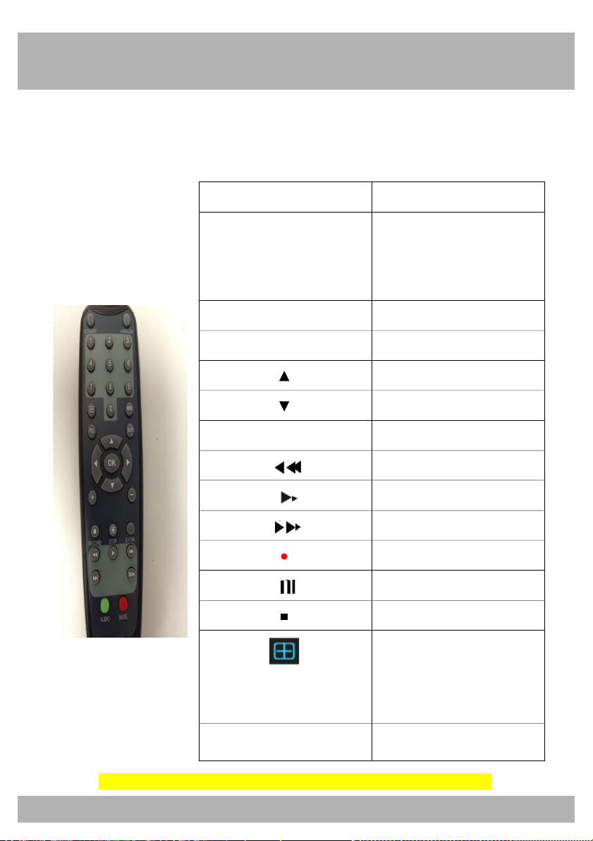
Use the remote control to navigate through the DVR’s menus.
Button Function
Select channels / Input
1-0
numbers in currently
selected field
ALL Display all channels
MENU Enter / Exit Menu
Up
Down
SEL Select
Rewind
Play
Fast Forward
Record
Pause / Playback
Stop
Allows you to view
PTZ
cameras in Quad view.
Controls PTZ camera.
Please keep in mind a PTZ camera is not included in your security kit.
Enable or disable Sound
Page 17
Chapter 6: DVR Components
17
Chapter 7: DVR Installation
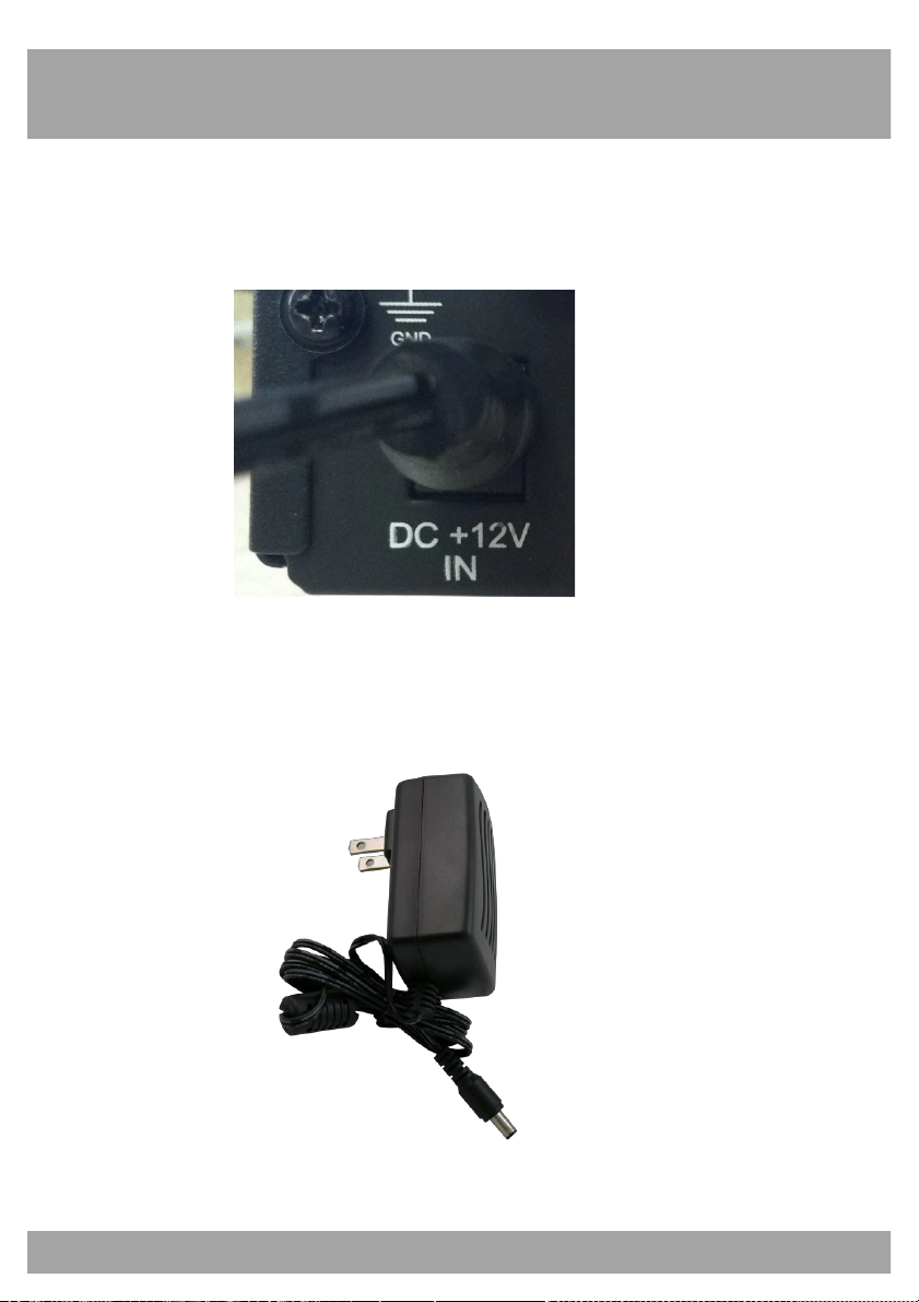
7.1 Connecting the Power Supply
1. Plug the included power adapter cable into the back of the DVR.
2. Plug the other end of the power adapter cable into an available wall
outlet (or, if you are using an uninterruptable power supply, plug the
adapter cable into one of its output sockets).
Page 18
18
Chapter 7: DVR Installation
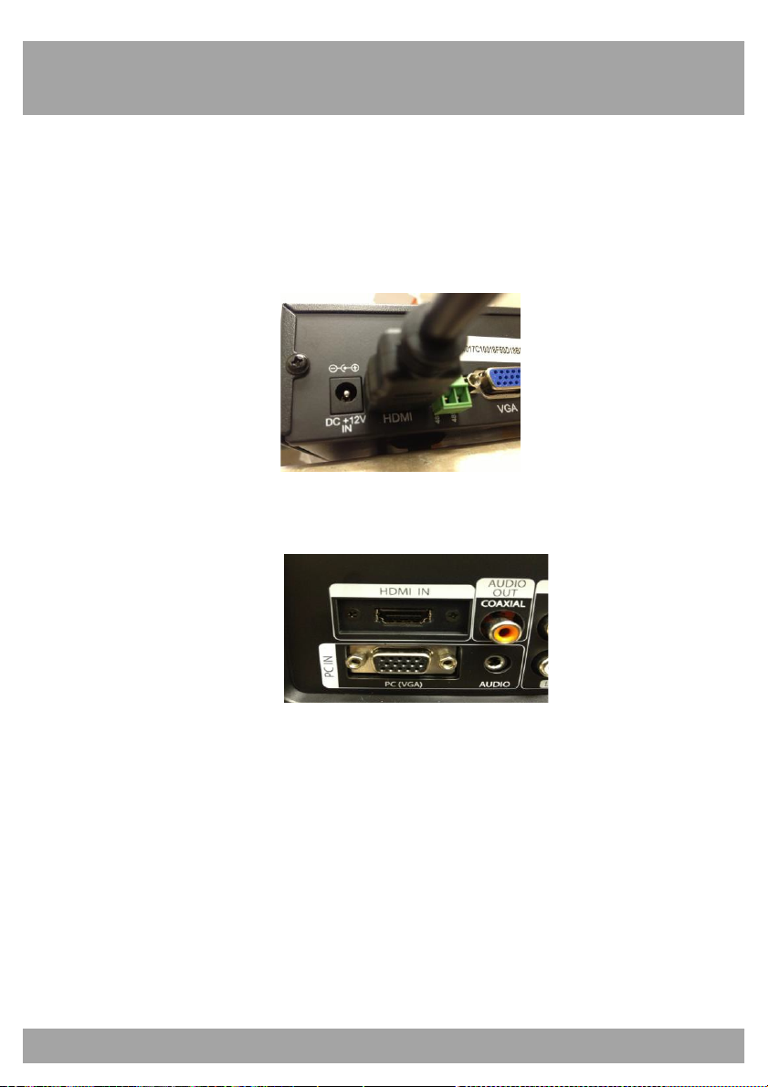
7.2 Connecting the DVR to a TV or Monitor
Using the supplied HDMI connector:
1. Connect the HDMI connector to the back of the DVR’s HDMI port.
2. Connect the other end of the cable to an available HDMI input on
your TV or monitor.
3. Select the appropriate video input channel on your TV or monitor
to view the DVR.
Note: If your TV does not have an HDMI port, you will need to purchase a
VGA or a BNC-to-RCA video cable. For a VGA connection, attach one end
of the VGA cable into your DVR’s VGA port and the other end into your
TV’s VGA port. For a BNC-to-RCA connection, attach the cable’s yellow
RCA video connector to a yellow Video Input port on your TV, and the
cable’s BNC video connector to the Video Out (V-OUT) port on the back of
the DVR.
Page 19
Chapter 6: DVR Components
19
Chapter 8: Camera Installation
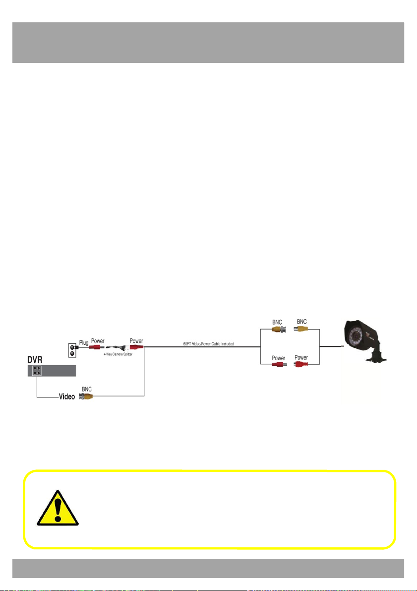
8.1 Connecting Cameras to the DVR
1. Your DVR system comes with one 60-ft. coaxial cable per camera.
Connect each cable to a camera using the BNC connectors (yellow
connector) and the DC connectors (red connector).
2. Plug the other end of the cables into the Video Input ports on the
back panel of the DVR.
3. Connect the provided four-way power splitter cable into the DC
connectors of the cables.
4. Plug the power splitter into the camera power supply.
5. Plug the camera power supply into an available wall outlet or
uninterruptable power supply.
Make sure all cameras are working (prior to mounting them) by
connecting them as described in the section above. Once all
cameras are confirmed to be fully operational, you can run the
cables and mount the cameras at their final locations.
Page 20

20
Chapter 8: Camera Installation
8.2 Mounting the Cameras
1. Choose a location: Decide where you would like to mount the
camera.
2. Indicate screw positions: Mark three holes on the surface where
you plan to mount the camera, using the holes in the camera base
as a guide.
3. Anchor screws: Using a drill bit slightly smaller than the included
screw anchors, drill into the mounting surface using the guide
marks you placed in the previous step. Insert the screw anchors.
4. Mount the camera: Hold the camera in place and tighten each
screw securely into the anchors.
5. Make sure the camera is secure: Once the camera's mount is
screwed in place, make sure that the camera is securely mounted
by placing gentle pressure on the mount.
6. Adjust the camera position: Adjust the camera housing to point
the camera lens in the direction you would like to record.
Don’t feel like installing the system yourself?
Let InstallerNet do the work for you.
Contact us at 1-800-806-5513 or visit us at
www.nightowlsp.com
Page 21
21
Chapter 9: DVR Start-up
9.1 System Initialization
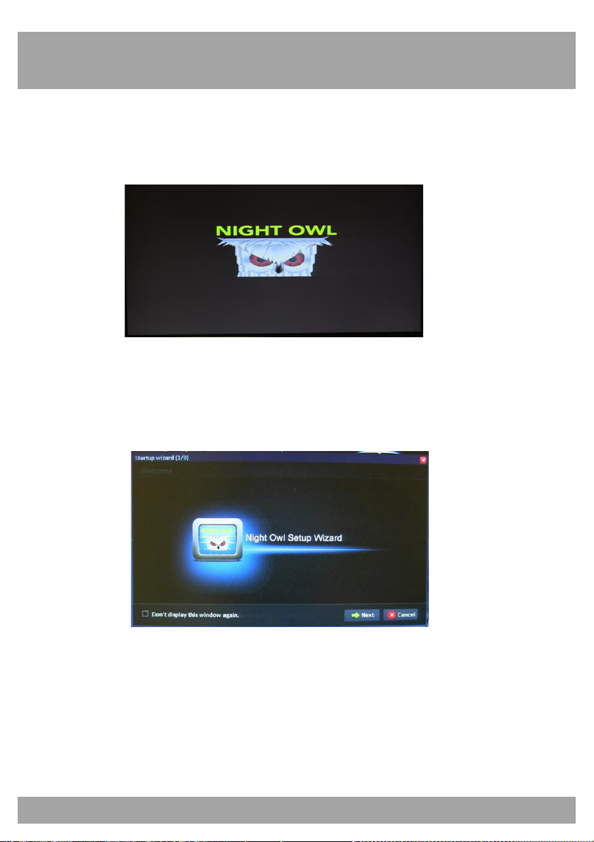
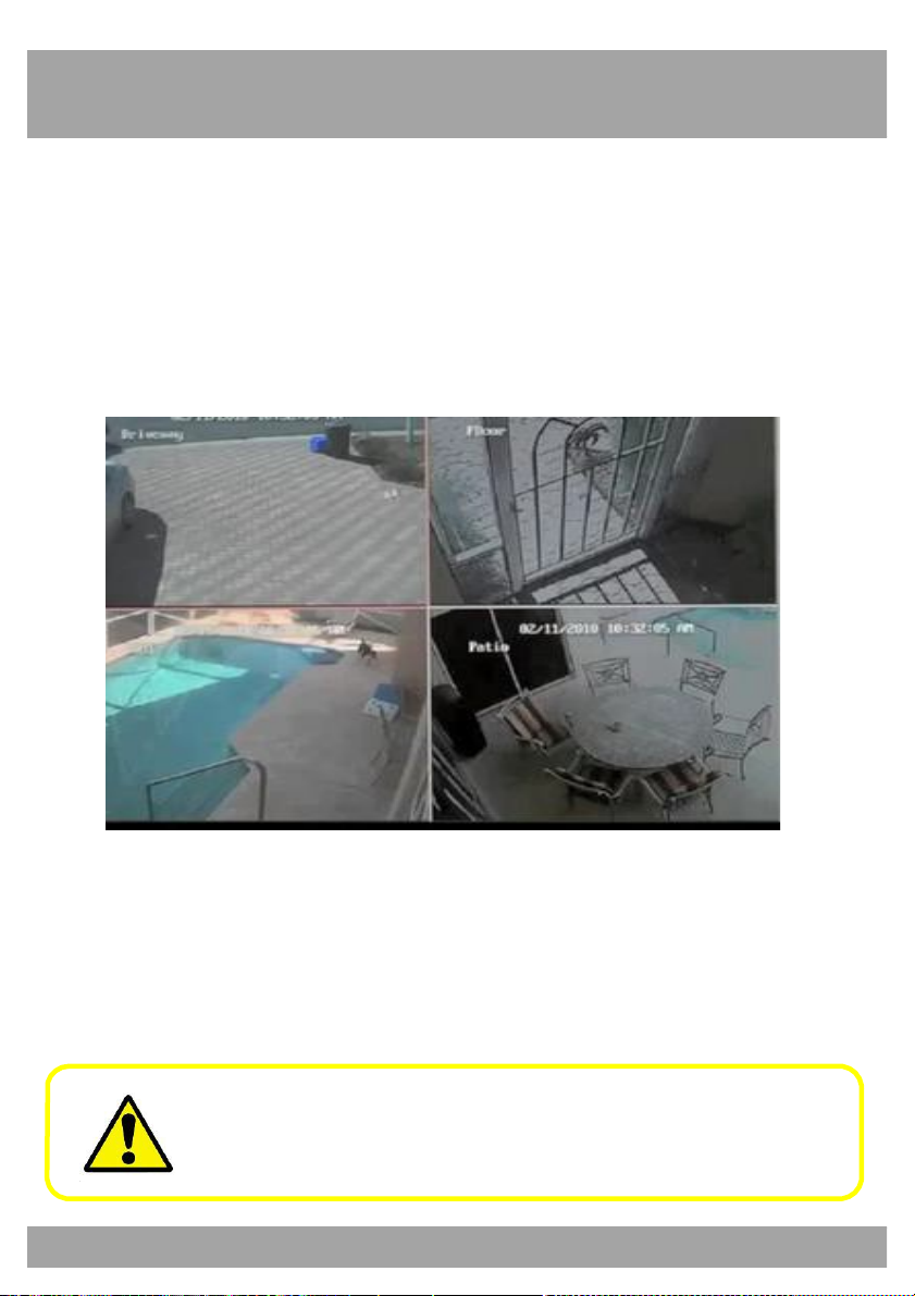
After you plug in the power adapter, the DVR will automatically start up and
display the Night Owl logo on your TV while initializing.
After initialization, your screen will display the Startup Wizard.
Page 22
22
Chapter 9: DVR Start-up
9.2 On-Screen Display
The on-screen display will show the following information:
• Date & Time: Displays the date and time on the system.
• Channel Title/Number: Displays the channel name, which you can
set in the Camera Menu.
By default, passwords are disabled on the system. However, for
security purposes, it is highly recommended that you enable a
system password (this is discussed in detail later).
Page 23
23
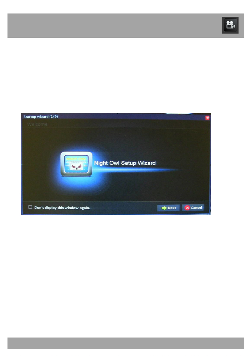
Chapter 10: Startup Wizard
Use the Startup Wizard to enter the security system’s basic settings,
network settings, record settings, and HDD settings.
The Startup Wizard will open when the DVR is powered on.
Refer to the Startup Guide for step-by-step instructions on using the
Startup Wizard.
Page 24
24
Chapter 11: Login Screen
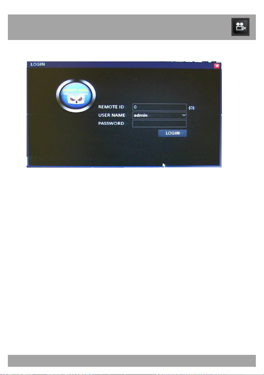
Before you can access any menus, you must log in.
• Remote ID: This number should match the number in parentheses
to the right of the field.
• User Name: Enter the user name you created in the Startup
Wizard or the User Menu. If you have not created a user name,
leave this setting as “admin.”
• Password: Enter the password that you created in the Startup
Wizard or the User Menu. If you have not created a password, this
field should remain empty.
• Login Button: Select this button when you have entered your user
name and password (if any).
Page 25
25
Chapter 12: Main Menu
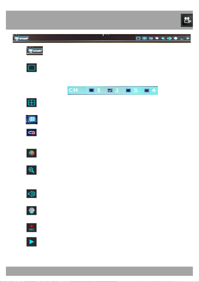
Opens the menu interface.
Allows you to check one channel at a time to enlarge the selected
channel to a full-screen view.
Allows you to enter into Quad-screen view.
Allows you to enter into Octad-screen view.
Allows you to start/stop an auto sequence. This will display the
cameras as a slide show.
Opens the color settings menu to adjust the colors of the camera.
Allows you to zoom in to a specific area of the camera view that
you have selected.
Opens the volume menu.
Opens the PTZ functions menu.
Allows you to start/stop continuous recording.
Opens the Playback menu.
Page 26
26
Chapter 13: Menu Icons
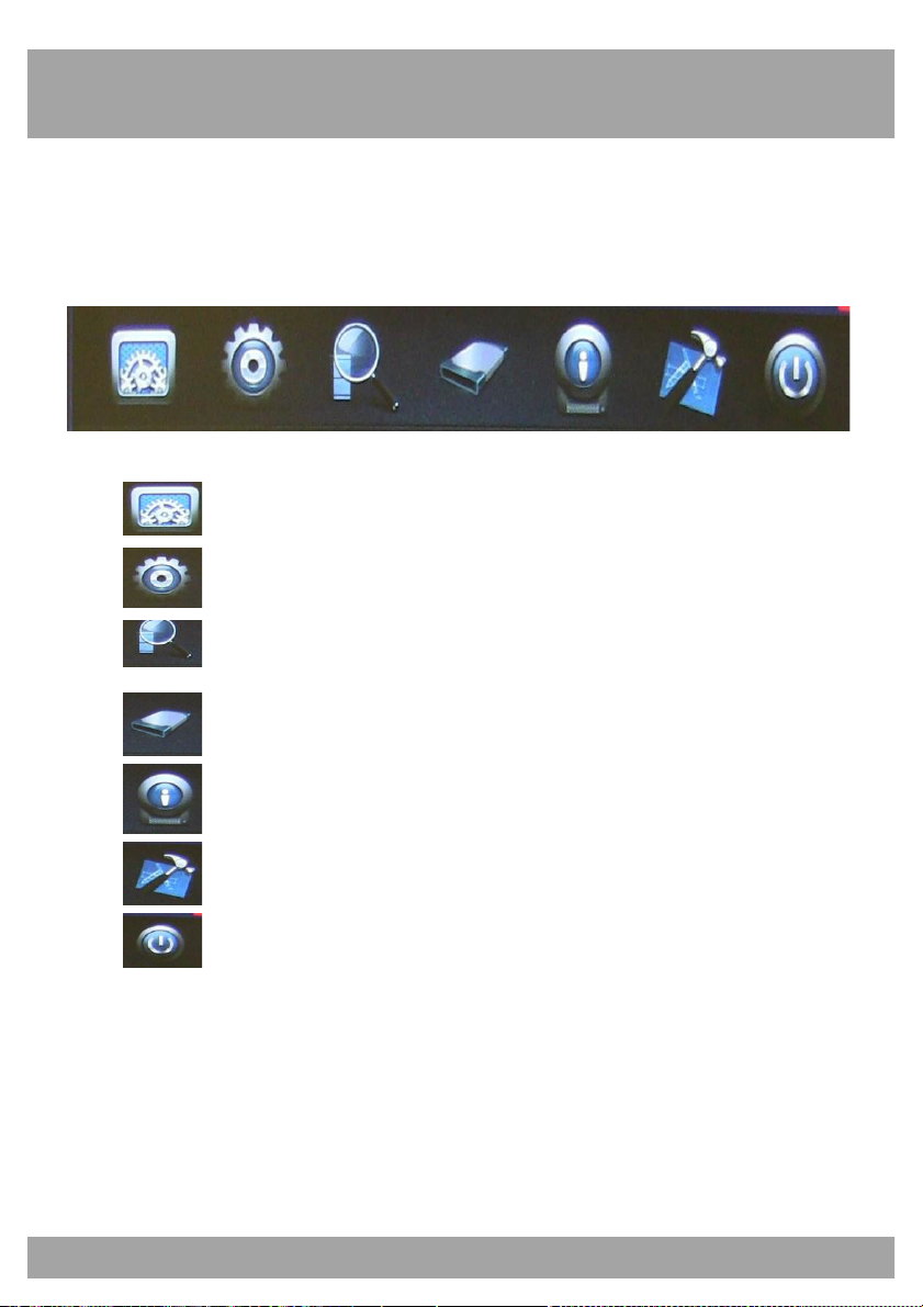
When you open the Main Menu you will see a line of icons at the top of the
screen. Each icon represents a different menu. The menu names are listed
below.
Basic Menu
Advanced Menu
Record Search Menu
Disk Management
Information Menu
Maintenance Menu
Exit
Page 27
27
Chapter 14: Basic Menu
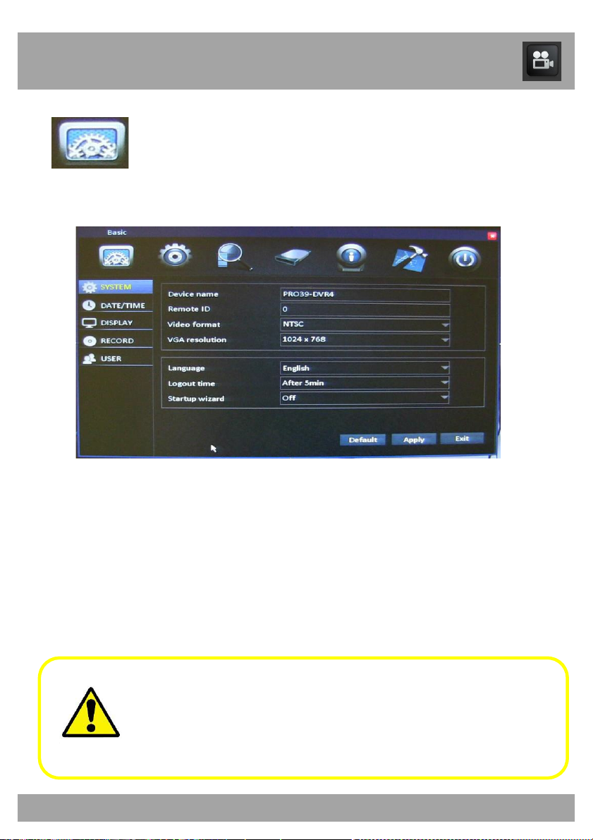
Basic Menu
Use the Basic Menu to access the System, Date/Time, Display, Record,
and User menus.
Be sure to Apply all changes you make in the menus. If you do
not apply the changes, they will not be saved.
You can also select the Default button on any page to restore the
DVR’s default settings.
Page 28
28
Chapter 14: Basic Menu
14.1 System Menu
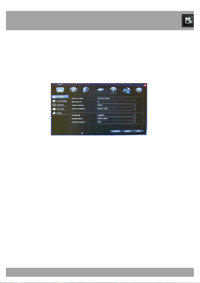
The System Menu allows you to change the language, output resolution,
logout time, and turn the Startup Wizard on/off. It is recommended that you
leave the Device Name and Remote ID fields at their default values. To
access the System Menu, select the Basic button, and then select System
from the list on the left side of the screen.
• Device Name: Displays the DVR you are using.
• Remote ID: Indicates the number of the DVR if there are multiple
DVRs at one location.
• Video Format: Leave this setting at NTSC unless you are using a
PAL-format TV.
• VGA Resolution: Select the resolution of the video output from the
VGA port. The larger the number, the better the resolution will be.
(However, a higher resolution will use more hard disk space when
recorded video is stored.) Refer to your TV/monitor manual to see
which resolution works best.
• Language: Set the language to English, French, or Spanish.
• Logout Time: This will allow the DVR to logout the user that is
signed into the DVR after a certain amount of time.
• Startup Wizard: Allows you to turn the Startup Wizard on/off when
the DVR is rebooted/turned on.
Page 29
29
Chapter 14: Basic Menu
14.2 Date/Time Menu
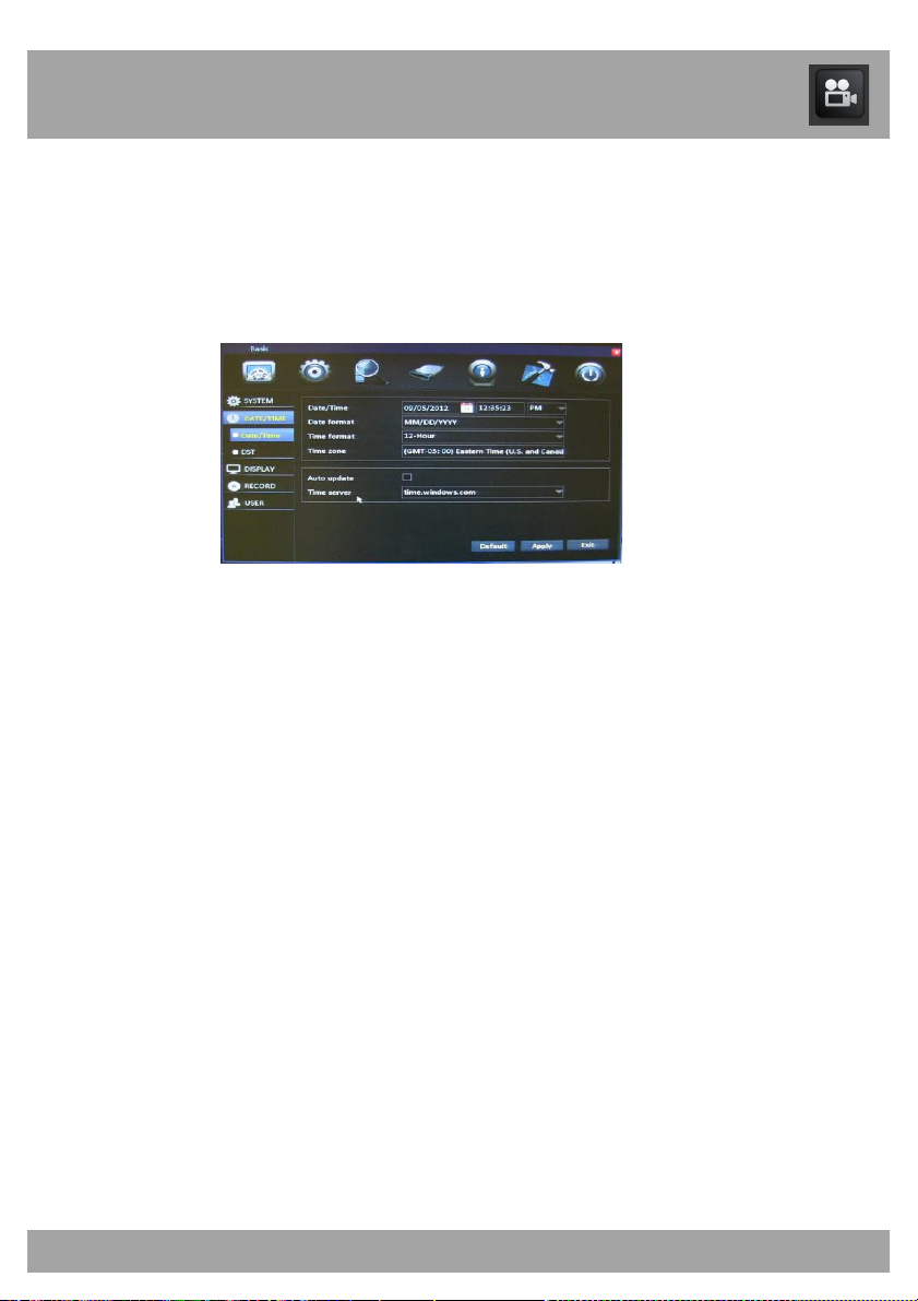
You should set the date and time when first setting up your system. You can
also configure Daylight Saving Time (DST) settings.
To access the Date/Time Menu, select the Basic button, and then select
Date/Time from the list on the left side of the screen.
• Date/Time: Input the current date using the date format that has
been selected, and input the current time using the time format that
has been selected. If you have selected the 12-hour format, you will
have to differentiate between AM and PM.
• Date Format: Use the drop-down menu to choose the way that you
would like the date displayed.
• Time Format: Use the drop-down menu to choose the way that
you would like the time display.
• Time Zone: Use the drop-down menu to choose the time zone in
which you are located. Keep in mind that if you have already
manually changed the date/time.
• Auto Update: Select this box if you would like the DVR to
automatically update the date/time. Keep in mind that this feature
will only work if the network settings have been configured properly.
• Time Server: You will generally not need to change this setting.
This is the web address that updates the date and time.
Page 30
Chapter 14: Basic Menu
30
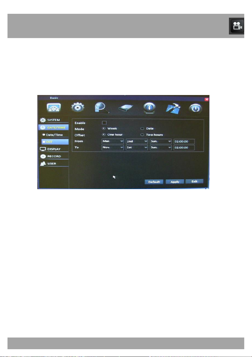
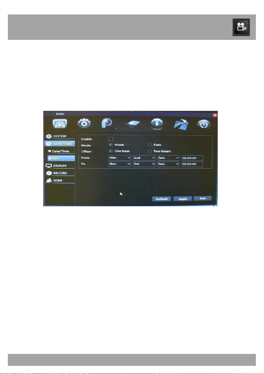
14.2.2 DST Menu
Use the DST Menu to configure Daylight Saving Time settings.
To access the DST Menu, select the Basic button, select Date/Time from
the list on the left side of the screen, and then select DST.
• Enable: Select this box if you would like to enable the Daylight
Saving Time settings.
• Mode: Depending on the Daylight Saving Time settings, you can
choose between the exact date and the week.
• Offset: Depending on the Daylight Saving Time settings, you can
choose between one hour and two hours. Generally this should be
set to one hour.
• From: The date/time that Daylight Saving Time begins.
• To: The date/time that Daylight Saving Time ends.
Page 31
Chapter 14: Basic Menu
31
14.3.1 Display Menu
Use the Display Menu to configure channel name, channel masking, color,
and time/name settings.
To access the Display Menu, select the Basic button and then select
Display from the list on the left side of the screen.
• CH: Indicates the channel that you will be configuring.
• Name: Give each channel a descriptive name if you wish (for
example, Warehouse).
• Mask: Opens a window that allows you to block out certain areas of
the channel screen.
• Color: Opens a window that allows you to adjust the colors in the
channel that is being recorded.
• Time/Name: Opens a window that allows you to show/remove the
date/time and the channel name displayed on the screen.
Page 32
Chapter 14: Basic Menu
32
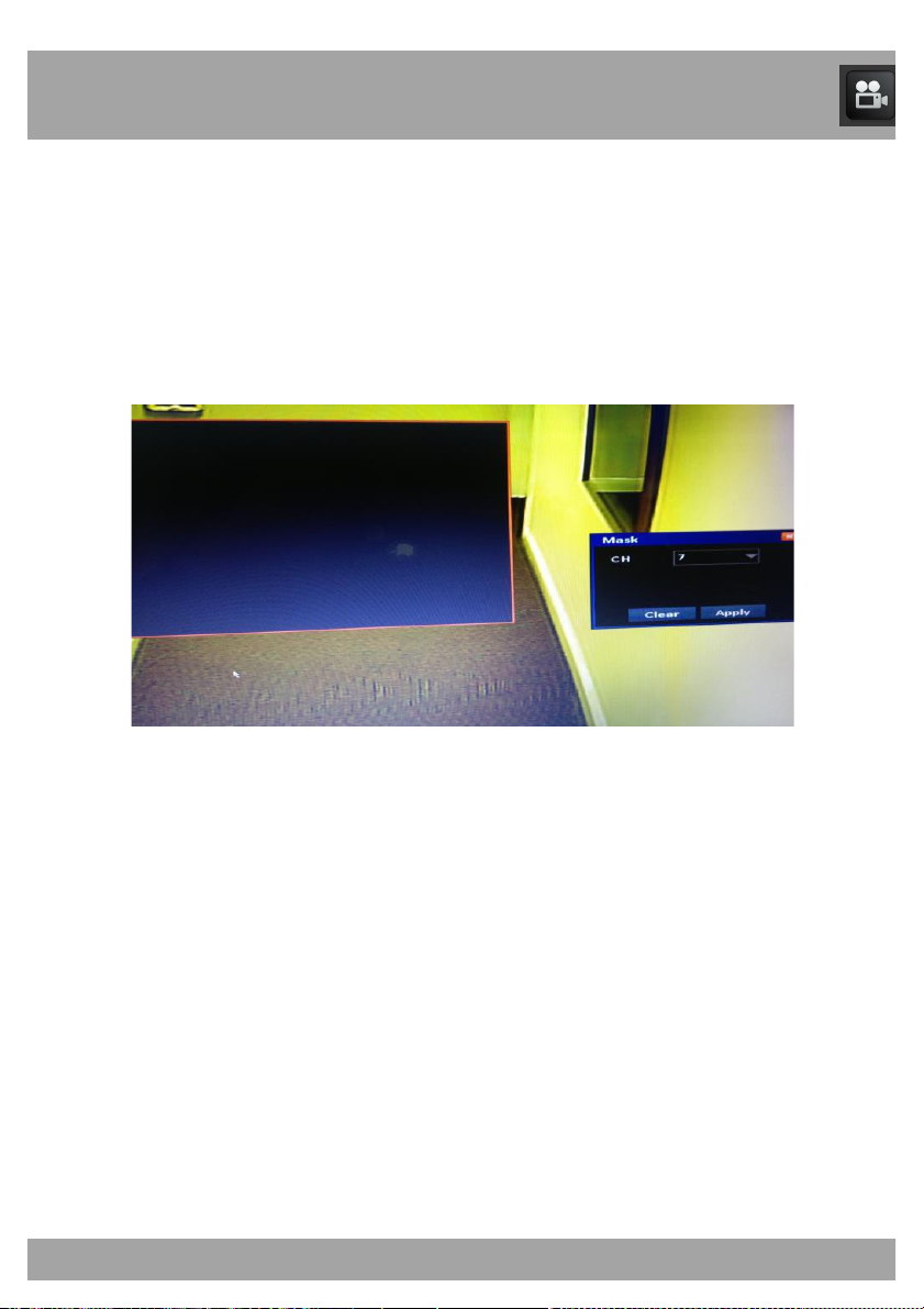
14.3.1.1 Mask Screen
Use the Mask Screen to block out certain areas of a channel screen.
To access the Mask Screen, select the Basic button, and then select
Display from the list on the left side of the screen. Select the Settings
button in the Mask column.
• CH: Indicates the channel that you will be configuring.
• Once you have selected the channel, left-click the mouse on the
screen.
• Drag the mouse over the area of the screen you would like to block
out.
• If you want to block out a different area or no area at all, select the
Clear button.
• Once you have selected an area to block out, select the Apply
button. This allows you to return to the menu screen.
Page 33
Chapter 14: Basic Menu
33
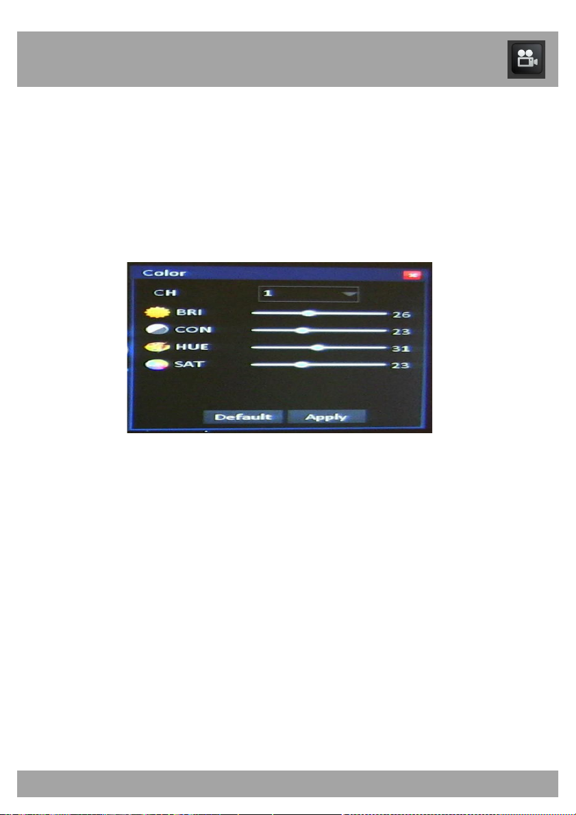
14.3.1.2 Color Screen
Use the Color Screen to adjust the colors of a channel that is being
recorded.
To access the Color Screen, select the Basic button and then select
Display from the list on the left side of the screen. Select the Settings
button in the Color column.
• CH: Indicates the channel that you will be configuring.
• Hue: Adjusts the color of the image by changing levels of the colors
red, green, blue, and yellow. You can adjust the color levels from 0
to 63.
• Brightness: Determines how bright or dark the image is. You can
adjust the brightness from 0 to 63.
• Contrast: Adjusts the contrast of the colors. You can adjust the
contrast from 0 to 63.
• Saturation: Adjusts the dominance of the hue colors. You can
Adjust this from 0 to 63.
• If you want to return to the original settings, select Default.
• Once you have made the appropriate changes, select the Apply
button. This allows you to return to the menu screen.
Page 34
Chapter 14: Basic Menu
34
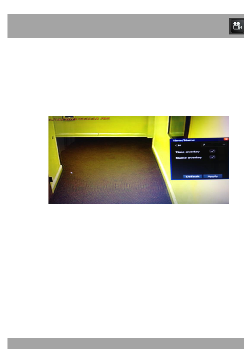
14.3.1.3 Time/Name Screen
The Time/Name Screen is used to show/remove the date/time and a
channel name displayed on the screen.
To access the Time/Name Screen, select the Basic button and then select
Display from the list on the left side of the screen. Select the Settings
button in the Time/Name column.
• CH: Indicates the channel that you will be configuring.
• Time Overlay: If you want the time to be displayed in this channel,
check this box. If you do not want the time to be displayed, uncheck
this box.
• Name Overlay: If you want the channel’s name to be displayed,
check this box. If you do not want the channel’s name to be
displayed, uncheck this box.
• If you want to return to the original settings, select the Default
button.
• Once you have made the appropriate changes, select the Apply
button. This allows you to return to the menu screen.
Page 35
Chapter 14: Basic Menu
35
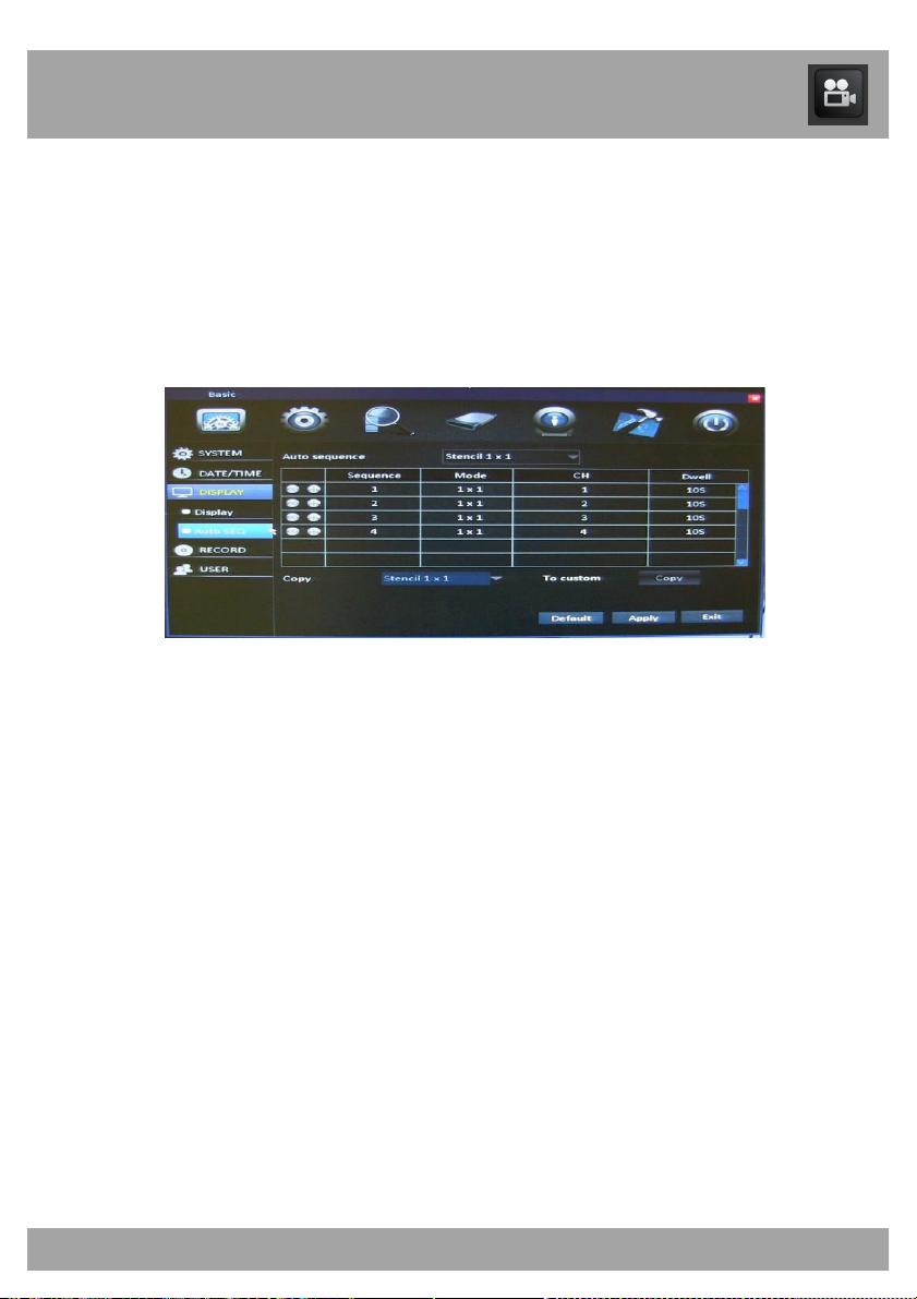
14.3.2 Auto SEQ Menu
Use the Auto SEQ Menu to adjust the channels and time that will be
displayed when you start the auto sequence.
To access the Auto SEQ Menu, select the Basic button, select Display
from the list on the left side of the screen, and then select Auto SEQ.
• Auto Sequence: Allows you to choose between Stencil 1x1,
Stencil 2x2, and Custom. Stencil 1x1 and Stencil 2x2 show each
channel in numeric order, one by one. Custom allows you to
change the sequence in which the channels are displayed.
• Sequence: Indicates the order in which the channels will be
shown.
• Mode: Indicates the view of the sequence (e.g., Stencil 1x1).
• CH: Indicates the channel that will be viewed for that sequence
number.
• Dwell: Indicates how long the channel will be displayed before it
switches to the next sequence.
• Copy: This option will only be available if you have chosen Custom
under Auto Sequence. Allows you to copy Stencil 1x1 to all.
• To Custom: Select this button to copy Stencil 1x1 to all channels.
Page 36
Chapter 14: Basic Menu
36
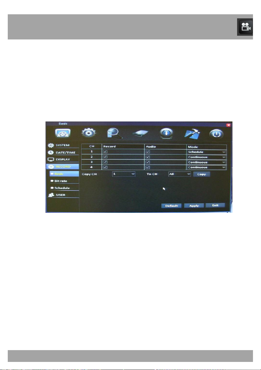
14.4.1 Record Menu
Use the Record Menu to enable recording, set audio preferences, and
specify how you would like to record on each channel.
To access the Record Menu’s basic functions, select the Basic button,
select Record from the list on the left side of the screen, and then select
Basic.
• CH: Indicates the channel that you will be configuring.
• Record: Check this box to enable recording on the channel.
• Audio: Check this box to enable audio recording on the channel.
• Mode: Select either Schedule or Continuous. Schedule allows
you to record motion, record continuously, or have no recording
during a specific time period. Continuous records constantly.
• Copy CH: Allows you to configure the settings on one channel and
copy them to another channel.
• To CH: Allows you choose the channel that you would like to copy
the configured settings to.
Page 37
Chapter 14: Basic Menu
37
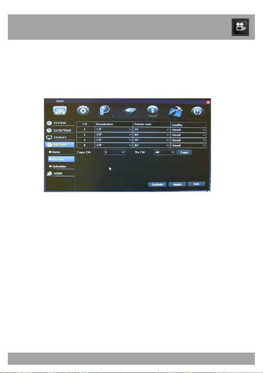
14.4.2 Bit Rate Menu
The Bit Rate Menu allows you to set the quality of the recorded video.
To access the Bit Rate Menu, select the Basic button, select Record from
the list on the left side of the screen, and then select Bit Rate.
• CH: Indicates the channel that you will be configuring.
• Resolution: Choose 960H (960x480) (Highest), D1 (704x480)
(High), WCIF (480x240) (Medium), or CIF (352x240) (Lowest)
resolution.
• Frame Rate: Allows you to allocate the frames per second (FPS)
per channel. This will determine the smoothness of the video during
playback; 30 FPS is real-time video.
• Quality: Set recording quality to Good, Better, Best or Normal.
• Copy CH: Allows you configure the settings on one channel and
copy them to another channel.
• To CH: Allows you choose the channel that you would like to copy
the configured settings to.
Page 38
Chapter 14: Basic Menu
38
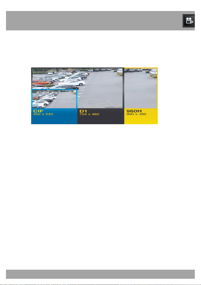
14.4.3 Resolution
Choose between 960H (960x480), WHD1 (960x240), D1 (704x480), HD1
(704x240), WCIF (480x240) or CIF (352x240) resolutions to record videos
To help maximize the DVR’s hard drive space, use the lowest resolution.
960H Resolution (960x480 pixels):
• The highest resolution.
• This is the best option if you would like to see details.
• Uses the most space on the hard drive.
WHD1 Resolution (960x240 pixels):
• High resolution.
D1 Resolution (704x480 pixels):
• Gives you the ability to blow up an image without it being pixilated.
HD1 Resolution (704x240 pixels):
• Medium resolution.
WCIF Resolution (480x240 pixels):
• Low resolution.
CIF Resolution (352x240 pixels):
• The lowest resolution.
• The image will become pixilated if it is blown up to see details.
• Uses the least space on the hard drive.
Page 39
Chapter 14: Basic Menu
39
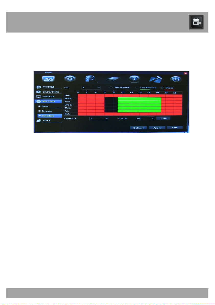
14.4.4 Schedule Menu
The Schedule Menu allows you to schedule recordings.
To access the Schedule Menu, select the Basic button, select Record from
the list on the left side of the screen, and then select Schedule.
• CH: Indicates the channel that you will be configuring. Select All to
set one recording schedule for all channels, or select individual
channels to set different recording schedules.
• Days and Times: Allows you to choose times to record and how
you would like to record. The days of the week are arranged in rows.
The hours of the day are arranged in columns and are set to military
(24-hour) time.
• Recording Types:
o Alarm Recording is indicated in Red
o Continuous Recording is indicated in Green
o No Recording is indicated in Black
• Check the box next to the recording type you want, and left-click
each box to indicate the type of recording for that hour. The box will
change to the color of the recording type you selected.
• Copy CH: Allows you to configure the settings on one channel and
copy them to another channel.
Page 40
Chapter 14: Basic Menu
40
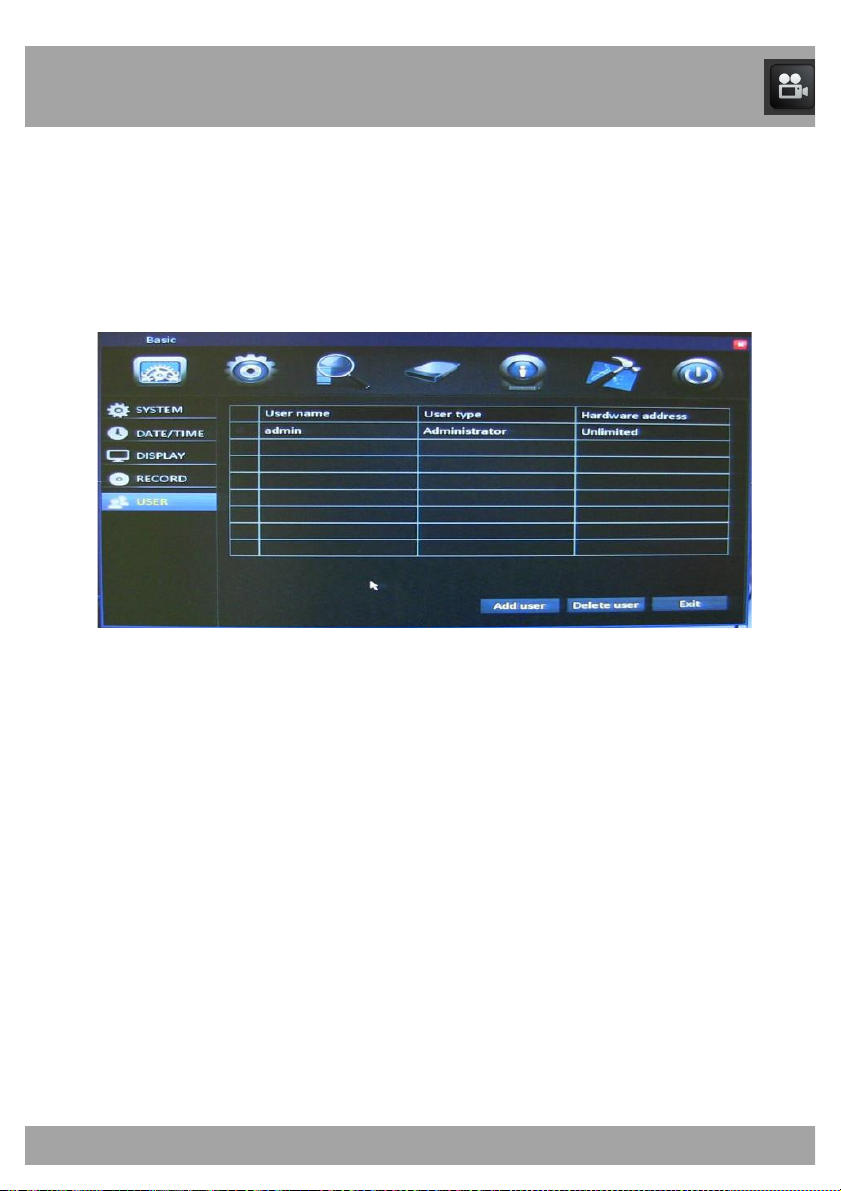
14.5 User Menu
The User Menu allows you to add users and permissions for those users.
To access the User Menu, select the Basic button, select Record from the
list on the left side of the screen, and then select User.
• User Name: Displays the names that you assign to users. To make
changes to a user, double-click on the user’s name.
• User Type: Displays the Administrator (only one administrator is
allowed) and Normal users (up to 5 normal users).
• Hardware Access: This will say Unlimited if the user can access
the DVR from any computer, or it will display the MAC address of
the computer that the user has been assigned to.
• Add User: Opens a new window to add a user.
• Delete User: Check the box located next to the User Name, then
select the Delete User button to delete that user.
Page 41
Chapter 14: Basic Menu
41
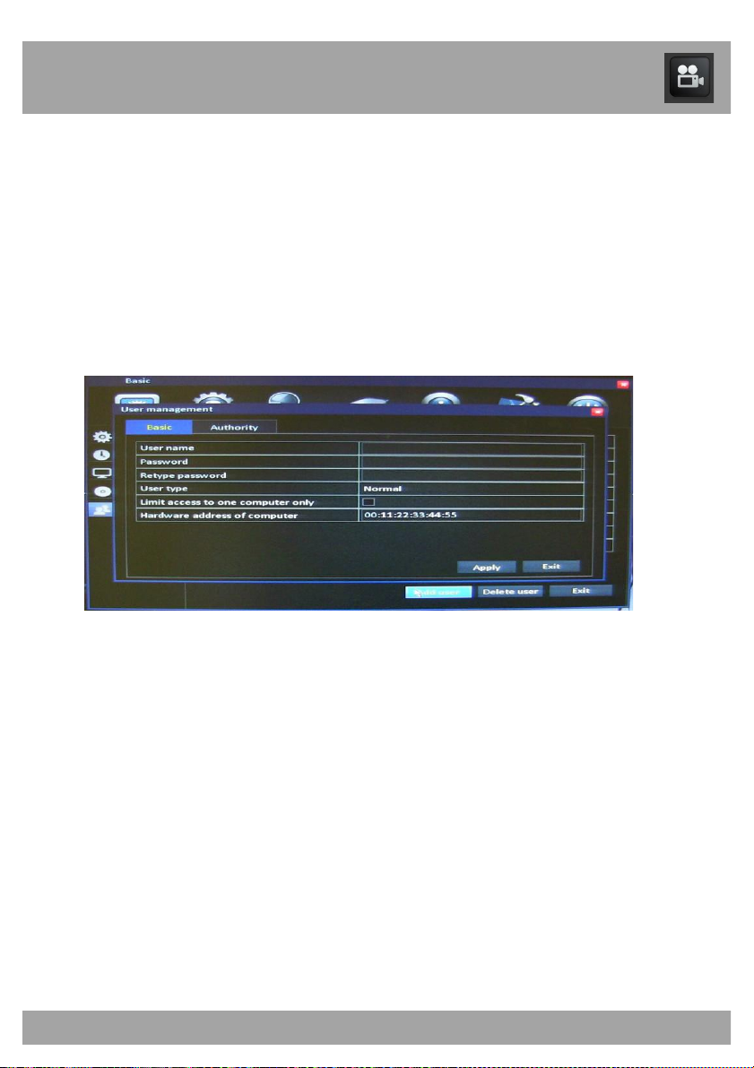
14.5.1 User Management Menu
Basic Tab
The User Management Menu allows you to add users and assign
permissions to those users.
To access the User Management Menu’s Basic Tab, select the Basic
button, select Record from the list on the left side of the screen, select
User, and then select Add User or double-click an existing user.
• User Name: Type the name you would like to assign to the user.
• Password: Enter a password that you will use to log in to the DVR.
Passwords are case-sensitive.
• Retype Password: Enter the same password as above.
• User Type: This will say Administrator (there can be only one
administrator) or Normal.
• Limit Access to One Computer Only: Check this box to limit who
can access the system.
• Hardware Address of Computer: Displays the hardware address
of the computer that the access was limited to.
Page 42
Chapter 14: Basic Menu
42
14.5.1 User Management Menu
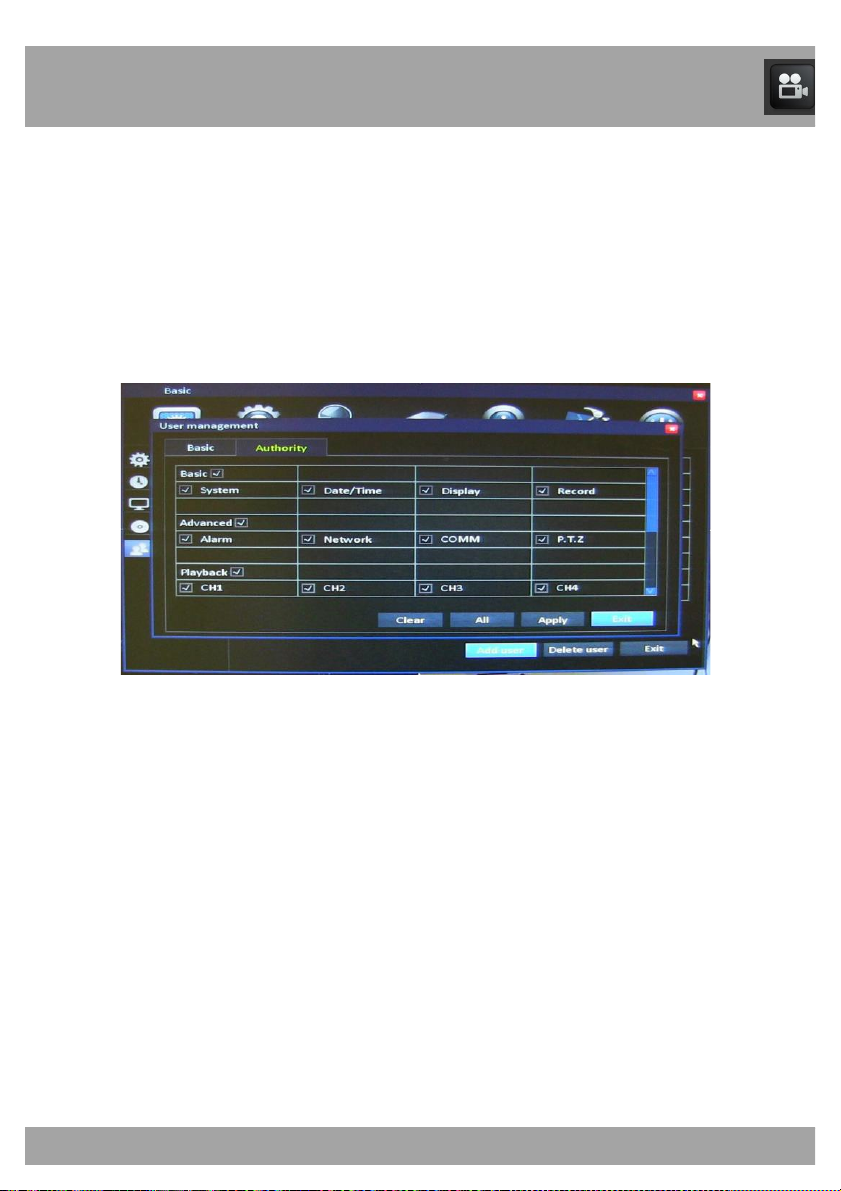
Authority Tab
To access the User Management Menu’s Authority Tab, select the Basic
button, select Record from the list on the left side of the screen, select
User, and then select Add User or double-click an existing user. You will
need to select the Authority Tab to limit access to certain menus for the
user.
• Each menu in the DVR will be listed with a check mark next the
menu name.
• Uncheck each box that you do not want the user to access.
• Select Apply and Exit.
Page 43
43
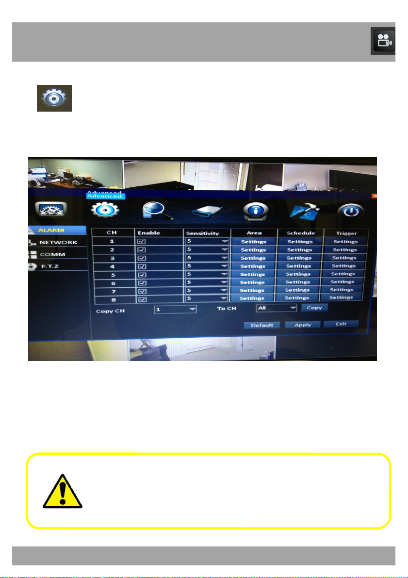
Chapter 15: Advanced Menu
Advanced Menu
Use this menu to access the Alarm, Network, Comm, and PTZ menus.
Be sure to Apply all changes made to the menus. If you do not
apply the changes, they will not be saved.
You can select the Default button on any page to restore the
DVR’s original settings.
Page 44
44
Chapter 15: Advanced Menu
15.1 Alarm Menu
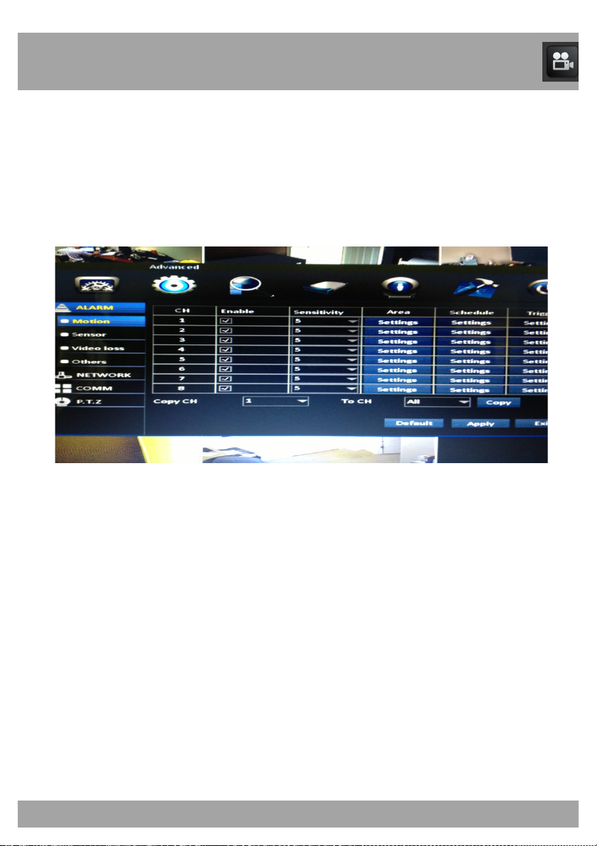
15.1.1 Motion Menu
The Motion Menu allows you to configure the motion settings on your DVR.
To access the Motion Menu, select the Advanced button, select Alarm
from the list on the left side of the screen, and then select Motion.
• CH: Indicates the channel that you will be configuring.
• Enable: Allows you to activate motion detection. It is recommended
that you keep this checked.
• Sensitivity: Indicates the level of sensitivity of the camera. The
lower the sensitivity, the more motion will be needed to start
recording.
• Area: Select Settings to open a new window to block out areas
that may have constant movement such as trees or roads.
• Schedule: Select Settings to open a new window that will show
when the DVR is set to record alarms.
• Trigger: Select Settings to open a new window that will allow you
to generate different responses by the DVR when motion has been
detected.
Page 45
45
Chapter 15: Advanced Menu
15.1.1.1 Area Screen
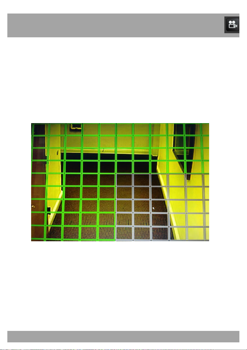
The Area Screen allows you to see areas that will and will not detect
motion.
To access the Area Screen, select the Advanced button, select Alarm from
the list on the left side of the screen, and then select Motion. Select
Settings in the Area column for the channel you are customizing.
• The green boxes show all active areas that will detect motion.
• The grey boxes show all inactive areas that will not detect motion.
Page 46
46
Chapter 15: Advanced Menu
15.1.1.2 Schedule Screen
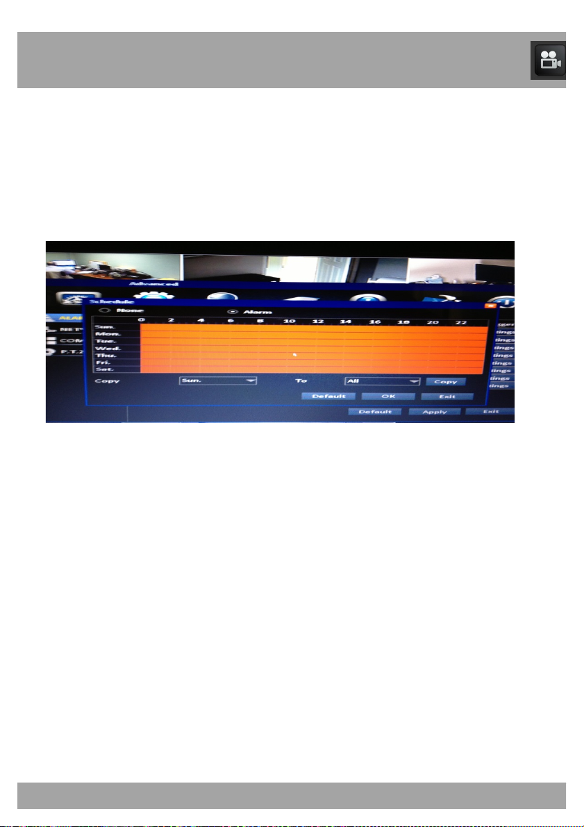
The Schedule Screen allows you to choose when to record.
To access the Motion Menu’s Schedule Screen, select the Advanced
button, select Alarm from the list on the left side of the screen, and then
Motion. Select Settings in the Schedule column for the channel you are
customizing.
• Days and Times: Allows you to choose times to record and how
you would like to record. The days of the week are arranged in rows.
The hours of the day are arranged in columns and are set to military
(24-hour) time.
• Recording types:
o Alarm Recording is indicated in Red
o Non-Alarm Recording is indicated in Black
• Select the recording, and then left-click each box to indicate the
type of recording for that hour. The box will change to the color of
the selected recording type.
• Copy: Allows you to configure the settings for one channel and
copy them to another channel.
• To: Allows you to choose the channel that you would like to
copy.
Page 47
47
Chapter 15: Advanced Menu
15.1.1.3 Trigger Screen
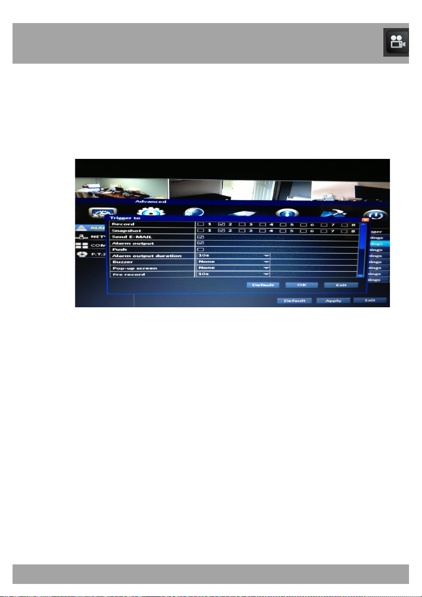
The Trigger Screen allows you see what has triggered an alarm.
To access the Trigger Screen, select the Advanced button, select Alarm
from the list on the left side of the screen, and then select Motion. Select
Settings in the Trigger column for the channel you are configuring.
• Record: Instructs the DVR to start recording when motion.
• Snapshot: Saves a picture of what has triggered the alarm.
• Send Email: Sends a snapshot to an email address that has been
configured.
• Alarm output: This has no function.
• Alarm output duration: This has no function.
• Buzzer: Causes the DVR to beep if alarms have been detected.
• Pop-up Screen: Enlarges the channel to the full screen of the
channel that has detected the alarm.
• Pre-Record: Select the duration that the DVR will record before an
alarm is triggered.
• Post-Record: Select the duration that the DVR will record.
• PTZ: If you have a PTZ (Pan-Tilt-Zoom) camera connected, select
whether you would like the camera to move to a preset point.
Page 48
48
Chapter 15: Advanced Menu
15.1.2 Video Loss Menu
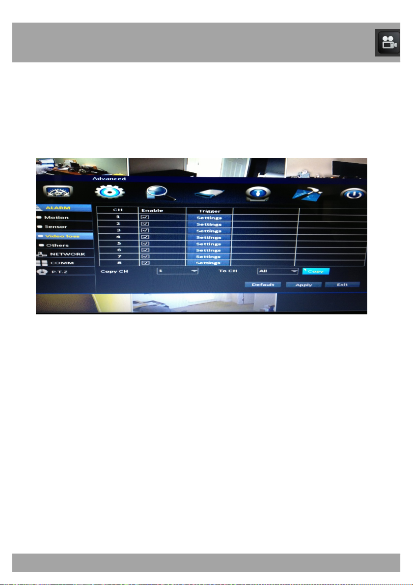
The Video Loss Menu allows you to configure the video loss settings on
your DVR.
To access the Video Loss Menu, select the Advanced button, select Alarm
from the list on the left side of the screen, and then select Video Loss.
• CH: Indicates the channel that you will be configuring.
• Enable: Allows you to activate the video loss alarm.
• Trigger: Select Settings to open a new window that will allow you
to generate different responses by the DVR when alarms have
been detected. (Refer to Chapter 15.1.1.3.)
• Copy CH: Allows you to configure the settings for one channel
and copy them to another channel.
• To CH: Allows you to choose the channel that you would like to
copy the configured settings to.
Page 49
49
Chapter 15: Advanced Menu
15.1.3 Others Menu
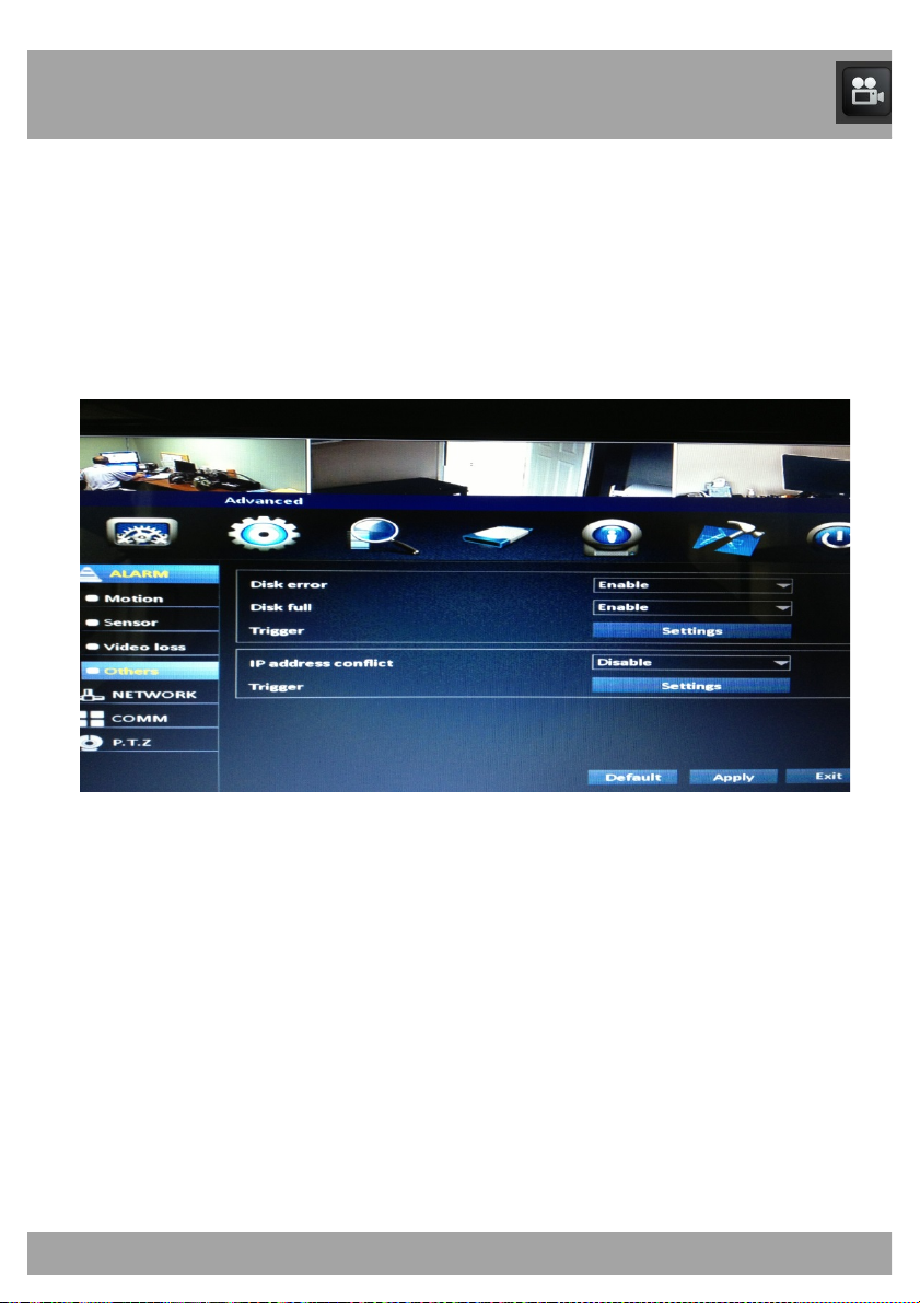
The Others Menu allows you to configure the settings on your DVR for
different alarm features.
To access the Others Menu, select the Advanced button, select Alarm
from the list on the left side of the screen, and then select Others.
• Disk Error: If you enable this option, you will be alerted if the hard
drive fails.
• Disk Full: If you enable this option, you will be alerted if the hard
drive becomes full.
• Trigger: Select Settings to open a new window that will allow you
to generate different responses by the DVR when alarms have
been detected. (Refer to Chapter 15.1.1.3.)
Page 50

50
Chapter 15: Advanced Menu
• IP Address Conflict: If you enable this option, you will be alerted if
the IP address of the DVR matches another device on the same
network.
Page 51
Chapter 15: Advanced Menu
15.2 Network Menu
51
15.2.1 LAN Menu
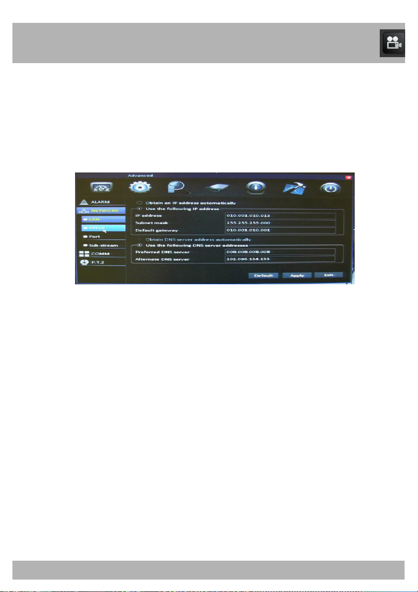
The LAN Menu allows you to configure the IP address for your DVR. Make
sure that the DVR is plugged directly into your internet router.
To access the LAN Menu, select the Advanced button, select Network
from the list on the left side of the screen, and then select LAN.
• The IP address/DNS server information can automatically be
obtained by the DVR if it is connected to a router/mode
connected to the internet. Select Obtain an IP address
automatically and Obtain DNS server address automatically.
• You can manually enter the IP address/DNS server information into
the DVR by selecting Use the following IP address and Use the
following DNS address and entering the correct information.
• IP Address: This is the identification of the DVR when it is
connected to a network.
• Subnet Mas
found in the network. It should always be set to 255.255.255.000.
• Default Gateway: This is the connection between two networks.
This should be the router’s IP Address.
• Preferred DNS Server: The primary DNS (Domain Name System).
• Alternate DNS Server: The secondary DNS server.
k: Describes the range of IP addresses that can be
m that is
Page 52
Chapter 15: Advanced Menu
52
15.2.2 PPPoE Menu
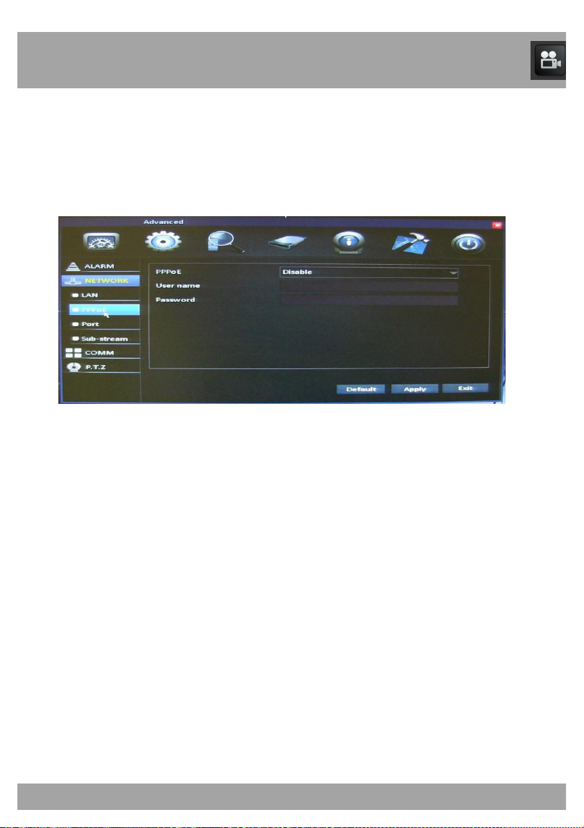
The PPPoE Menu allows you to configure the DVR using broadband dial-
up network access.
To access the PPPoE Menu, select the Advanced button, select Network
from the list on the left side of the screen, and then select PPPoE.
• You will need to use this option if you are using broadband dial-up
network access. You will have to enter a user name and password
that are provided by your Internet service provider.
• PPPoE: Enable this option if you are using broadband dial-up
network access.
• User Name: Provided by your Internet service provider.
• Password: Provided by your Internet service provider.
Page 53
Chapter 15: Advanced Menu
53
15.2.3 Port Menu
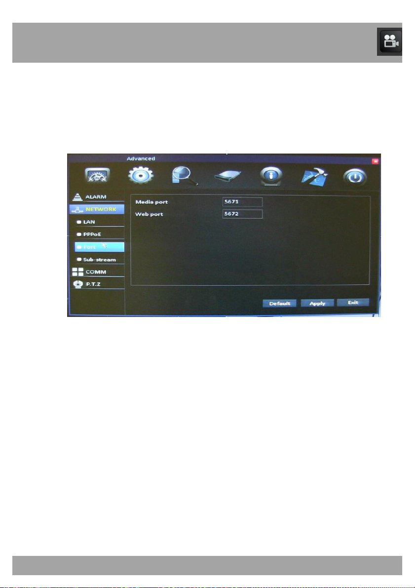
The Port Menu allows you to view your DVR through the Internet, software,
and mobile phones.
To access the Port Menu, select the Advanced button, select Network from
the list on the left side of the screen, and then select Port.
• Media Port: This needs to be set to 9000. It will allow you to
access to the DVR through the Control Management Software
(Nightowl View )
• Web Port: This needs to be set to 2051. This will allow access to
the DVR through the Internet.
Page 54
Chapter 15: Advanced Menu
54
15.2.4 Sub-Stream Menu
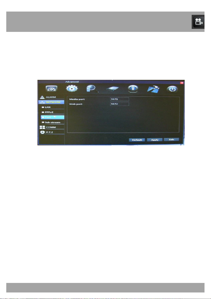
The Sub-Stream Menu allows you to configure the network settings.
To access the Sub-Stream Menu, select the Advanced button, select
Network from the list on the left side of the screen, then select
Sub-Stream.
• CH: Indicates the channel that you will be configuring.
• Resolution: Choose WCIF, WQCIF, CIF or QCIF resolution.
• Frame Rate: Allows you to allocate the FPS per channel. This will
determine the smoothness of the video during playback, 30 FPS is
real-time video.
• Quality: Set the recording to Good, Better, Best or Normal.
• Copy CH: Allows you to configure the settings on one channel and
copy them to another channel.
• To CH: Allows you to choose the channel that you would like to
copy the configured settings to.
Page 55
Chapter 15: Advanced Menu
55
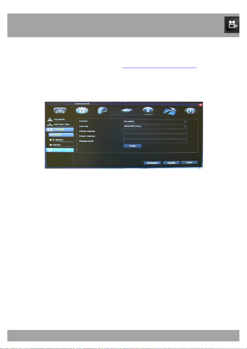
15.3.1 DDNS Menu
The DDNS Menu allows you to configure DDNS setup after you have
registered for a free domain name at http://www.nightowldvr.com.
To access the DDNS Menu, select the Advanced button, select COMM,
and then select DDNS from the list on the left side of the screen.
• DDNS: This should be set to Enable if you are using a DDNS
service.
• Server: This should be set to NightOwl when using Night Owl’s
free domain name service.
• Host Name: This should be set to the domain name that you
created during DDNS registration.
• Username: The UserID that you created during DDNS registration.
• Password: The password that you created during DDNS
registration.
• Test: Tests the settings to ensure that they work correctly.
Page 56
Chapter 15: Advanced Menu
56
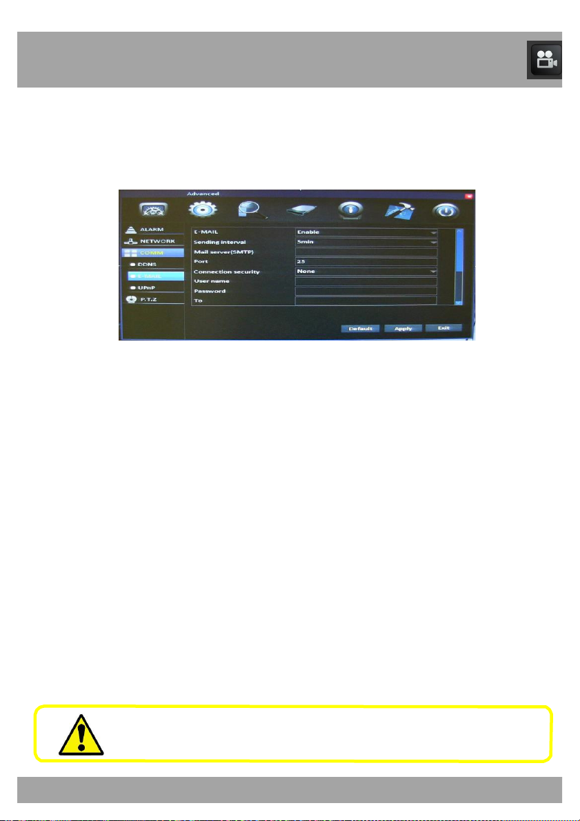
15.3.2 E-Mail Menu
The E-Mail Menu allows you to configure email alert settings.
To access the E-Mail Menu, select the Advanced button, select COMM,
and then select E-Mail from the list on the left side of the screen.
• E-mail: Allows you to enable/disable email alerts. If you have the
DVR set to Motion, you will receive an email alert with an attached
image of the object that triggered the alarm.
• Sending Interval: The period in between each email alert.
• Mail Server (SMTP): The SMTP Address that is determined by the
settings of your email provider.
• Port: Determined by the settings of your email provider.
• Connection Security: Determined by the settings of your email
provider.
• User Name: Your email address that sends the emails.
• Password: Your password for the email provided in the User
Name field.
• To: The email address that receives email alerts.
• CC: Additional email addresses that receive email alerts.
Please refer to your email provider for the settings for your email
account.
Page 57
Chapter 15: Advanced Menu
57
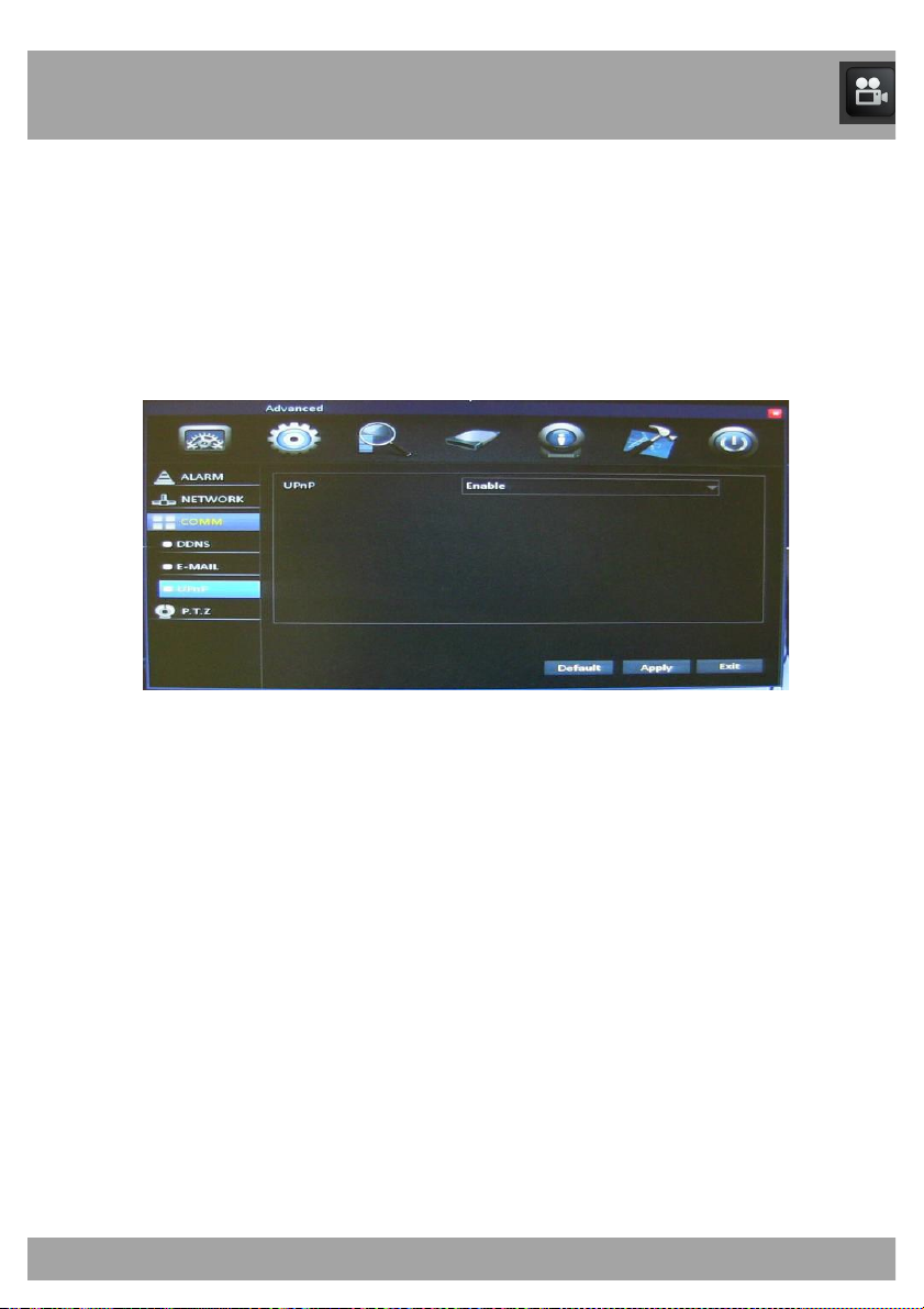
15.3.3 UPnP Menu
The UPnP Menu allows you to enable the UPnP (Universal Plug and Play)
setting of the DVR.
To access the UPnP Menu, select the Advanced button, select COMM, and
then select UPnP from the list on the left side of the screen.
• UPnP: Choose Enable to allow the DVR to use UPnP. This
enables your router and DVR to discover each other’s presence on
the network and establish a functional relationship for data sharing
and communication.
Page 58
Chapter 15: Advanced Menu
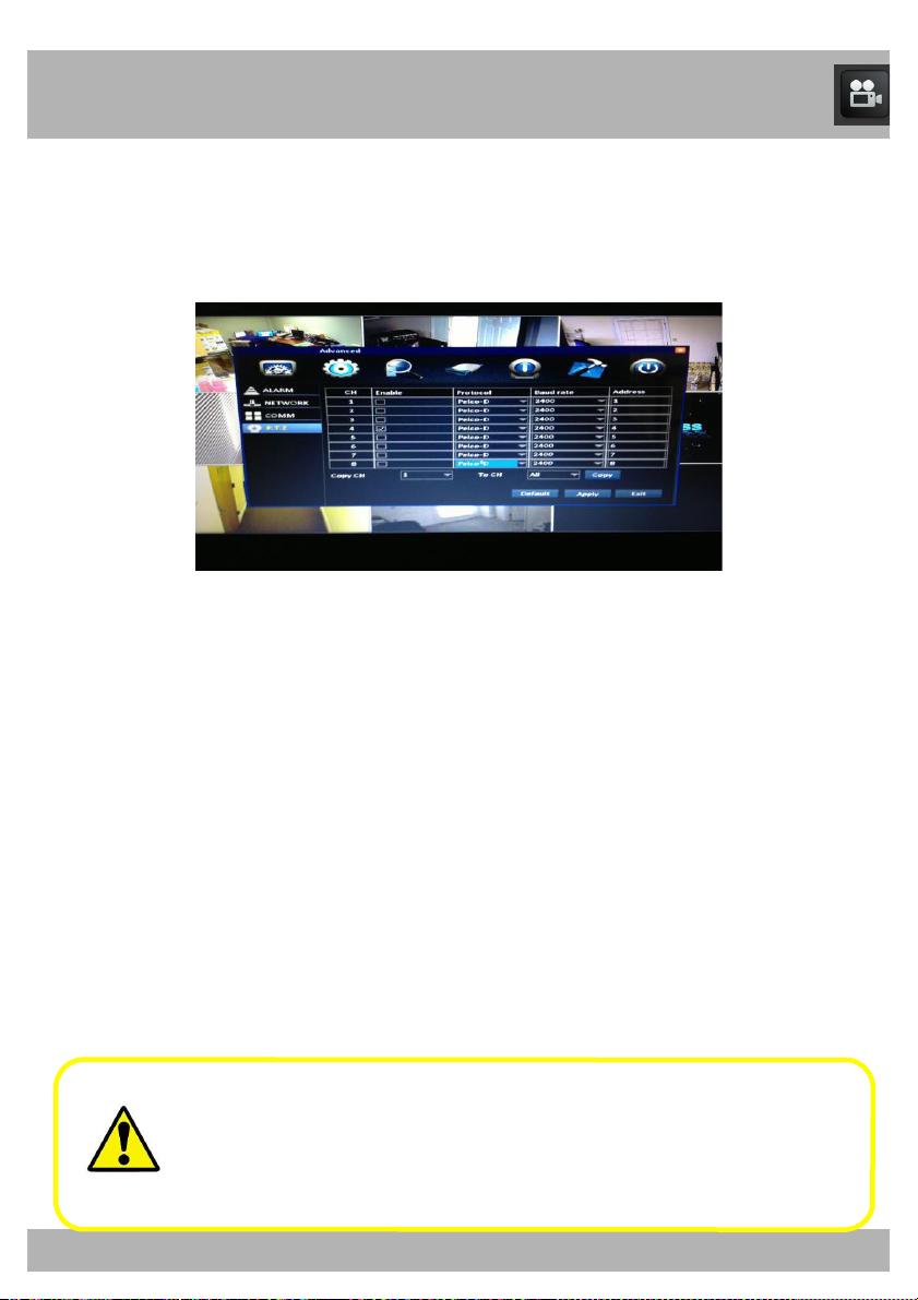
15.4 PTZ Menu
58
The PTZ Menu allows you to configure settings on your DVR to control a
PTZ (Pan Tilt Zoom) camera. (PTZ camera not included.)
To access the PTZ Menu, select the Advanced button and then select
P.T.Z. from the list on the left side of the screen.
Refer to your PTZ camera’s documentation for proper settings.
• CH: Indicates the channel that you will be configuring.
• Enable: Allows you to enable/disable
the controls, ensure that there is a check mark in the box.
• Protocol: Select PELCO-D or PELCO-P for the selected channel.
• Baud Rate: Select 1200, 2400, 4800, or 9600.
• Address: Enter an address from 001 to 255.
• Copy CH: Allows you to configure the settings for one channel and
copy them to another channel.
• To CH: Allows you to choose the channel to be copied.
Refer to your PTZ camer
PTZ camera is not included. Please keep in mind the Protocol
and Baud Rate settings are configured specific to your camera.
Night Owl cameras must be set to Pelco-D and 9600.
the PTZ controls. To enable
a’s instruction manual for further details.
Page 59
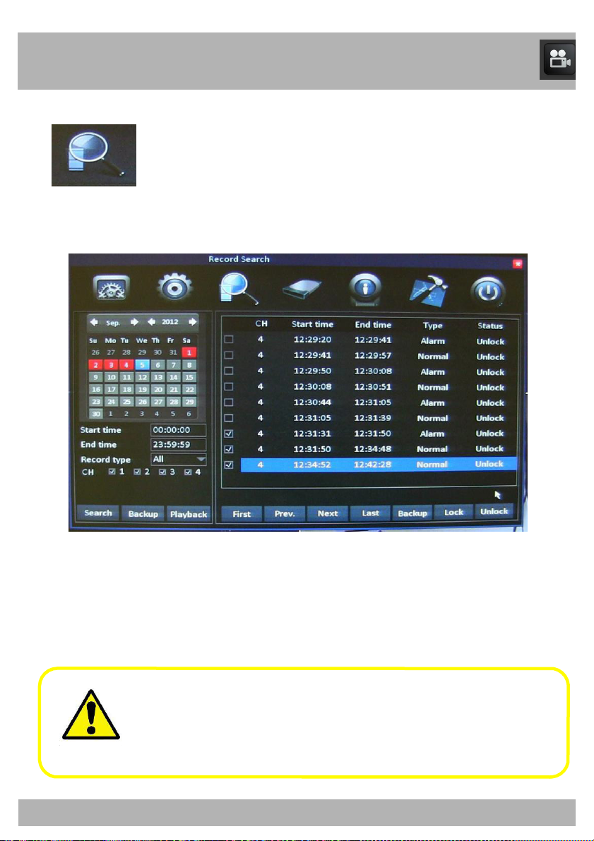
Chapter 16: Record Search Menu
Record Search Menu
59
Use this menu to find, play back, and back up recorded video.
Be sure to Apply all changes made to the menus. If you do not
apply the changes, they will not be saved.
You can also select the Default button on any page to restore the
DVR’s original settings.
Page 60
Chapter 16: Record Search Menu
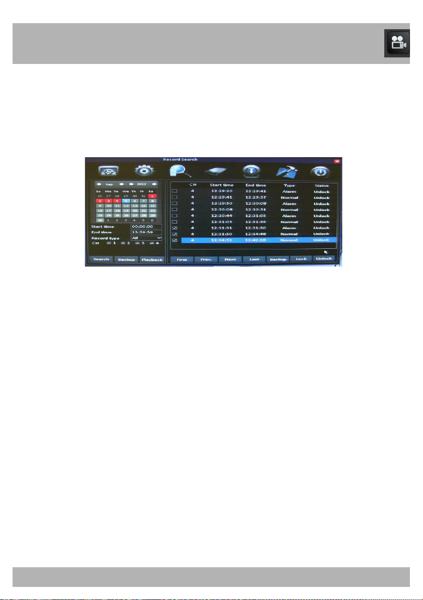
The Calendar lets you select the dates of recorded video you wish to play
60
back.
To access the Record Search Menu, select the Record Search button. The
Calendar appears on the left.
Calendar
• Left / Right Arrows: Switch between months and years.
• Start Time: Select the time of day that you would like to begin the
search.
• End Time: Select the time of day that you would like to end the
search.
• Record Type: Select the
• CH: Place a check mark in the box(es) beside the channel(s) that
you would like to play back.
• Search: Select this option when all information has been entered.
• Backup: Copies all currently selected files (indicated by the
checkbox in the list to the right) to a USB drive inserted into the
USB port on the back of the DVR.
• Playback: Allows you to view the playback scre
is highlighted in blue.
type of recording you will be searching.
en for the day that
Page 61
Chapter 16: Record Search Menu
61
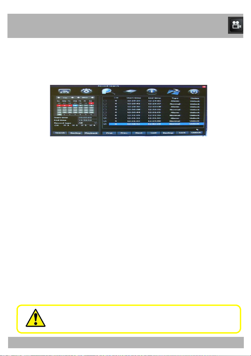
The File List shows a list of recordings.
To access the Record Search Menu, select the Record Search button. The
File List is on the right.
File List
• CH: Indicates the channel that was recorded.
• Start Time: Indicates the time that the recording began.
• End Time: Indicate the time that the recording ended.
• Type: Indicates the type of recording (Alarm or Normal).
• Status: Indicates whether the file has been
• First: Takes you to the first page of the list.
• Prev: Takes you to the previous page of the list.
• Next: Takes you to the next page of the list.
• Last: Takes you to the last page of the list.
• Backup: Copies all currently selected files (indicated by the
checkbox to the right of the file in the list) to a USB drive inserted
into the USB port on the back of the DVR.
• Lock: Locks the un
• Unlock: Unlocks the locked files.
Once files are backed up onto a USB drive, you will need to
convert the files to .avi format
locked files.
locked or unlocked.
Page 62
Chapter 16: Record Search Menu
62
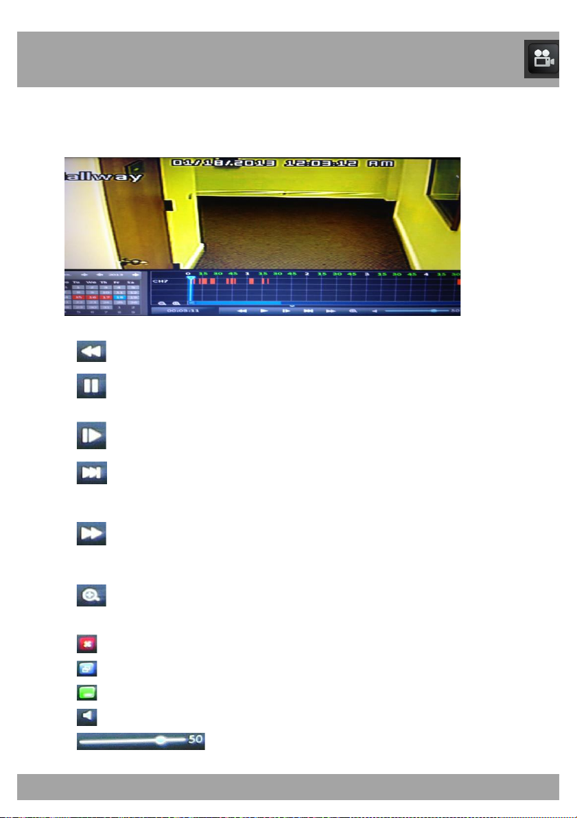
When you play back a recorded file, a number of controls are available.
Use the Calendar, File List, and Playback button to playback recorded files.
The playback screen has the following buttons:
Rewinds the recorded video.
Pauses/plays the recorded video.
Pauses the recorded video.
Plays back the recorded video in slow motion. Select repeatedly
to access different playback speeds.
Fast-forwards the recorded video. Select repeatedly to access
different playback speeds.
Zooms in on a particular area. (Click the area where you want to
zoom in.)
Exits the playback screen.
Minimizes the top half of the menu but leaves the controls.
Minimize the menu, including the controls.
Mutes/unmutes the sound.
Indicates the playback volume.
Page 63
Chapter 16: Record Search Menu
63
Chapter 17: Converting Files to AVI
Converting the .246 files to AVI format allows you to play back the recorded
files on most multimedia players.
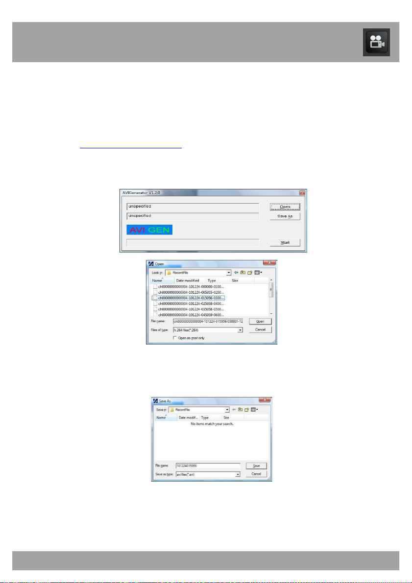
AVI conversion involves selecting a file and then converting.
• Download and install the AVI Generator from
www.NightOwlSP.com.
• Launch the program and select Open to browse to the .264
recording you would like to convert, and then select Open again.
• Select Save As to specify the location where you would like to
save the .avi file when the conversion is complete. You can
rename the converted file in the File Name field.
• Click Start to begin conversion from .264 to .avi.
Page 64
64
Chapter 18: Disk Management Menu
Disk Management Menu
The Disk Management menu allows you to view and manage recordings on
your DVR’s hard disk drive (HD).
Be sure to Apply all changes made to the menus. If you do not
apply the changes, they will not be saved.
You can also select the Default button on any page to restore the
DVR’s original settings.
Page 65
Chapter 16: Record Search Menu
65
Chapter 18: Disk Management Menu
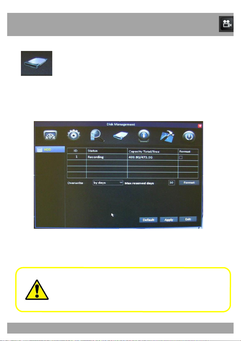
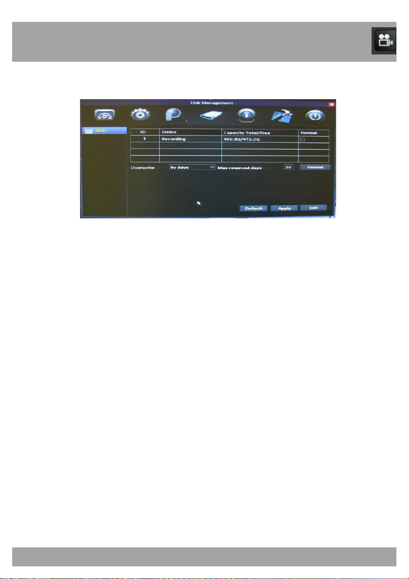
To access the Disk Management menu, select the Disk Management
button.
• Status: Indicates whether the HD is working (recording) or not
working (no disk).
• Capacity Total/Free: Shows the total HD space available and how
much free space is on the HD. The maximum HD capacity is 2
terabytes.
• Format: Check this box to enable the HD to be formatted.
• Format Button: Select this button to format the HD. Formatting the
HD will erase all data and allow the DVR to read and write files to
and from the HD.
• Overwrite: Choose one of three options: By days, By capacity, or
Never). This will write over the oldest files first.
• Max Reserved Days: This will only be shown if you choose the By
days option in the overwrite feature.
Page 66
Chapter 19: Information Menu
66
Information Menu
Use this menu to access the Device, Network, Online, and Record
Information menus.
Be sure to Apply all changes made to the menus. If you do not
apply the changes, they will not be saved.
You can also select the Default button on any page to restore the
DVR’s original settings.
Page 67
Chapter 19: Information Menu
67
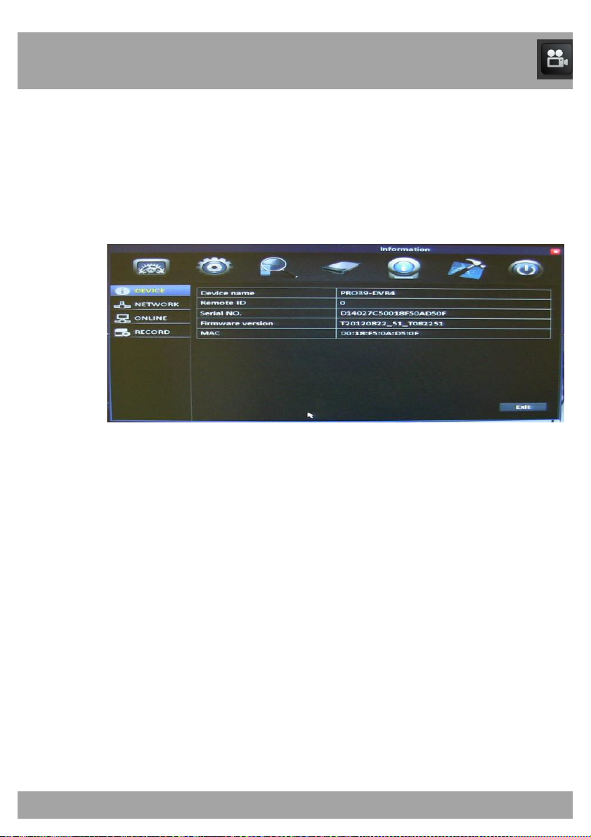
19.1 Device Menu
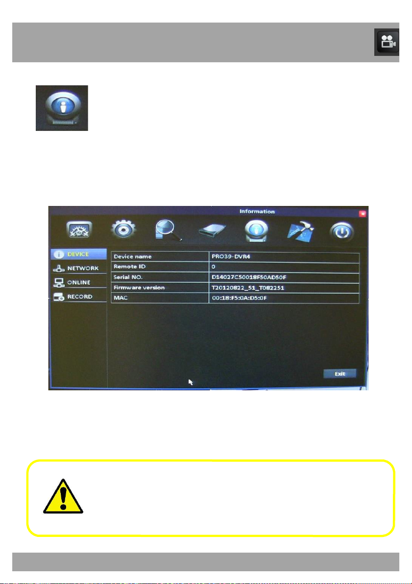
The Device Menu allows you to view the MAC Address, serial number and
the firmware version of your DVR.
To access the Device Menu, select the Information button and then select
Device.
• Device Name: The DVR’s name.
• Remote ID: The ID of the DVR if there are multiple DVRs in one
location.
• Serial No.: The serial number of the DVR.
• Firmware Version: The DVR’s firmware version. You will need to
refer to this information from time to time to determine whether the
DVR’s firmware needs to be updated.
• MAC: The unique identifier assigned to the DVR.
Page 68
Chapter 19: Information Menu
68
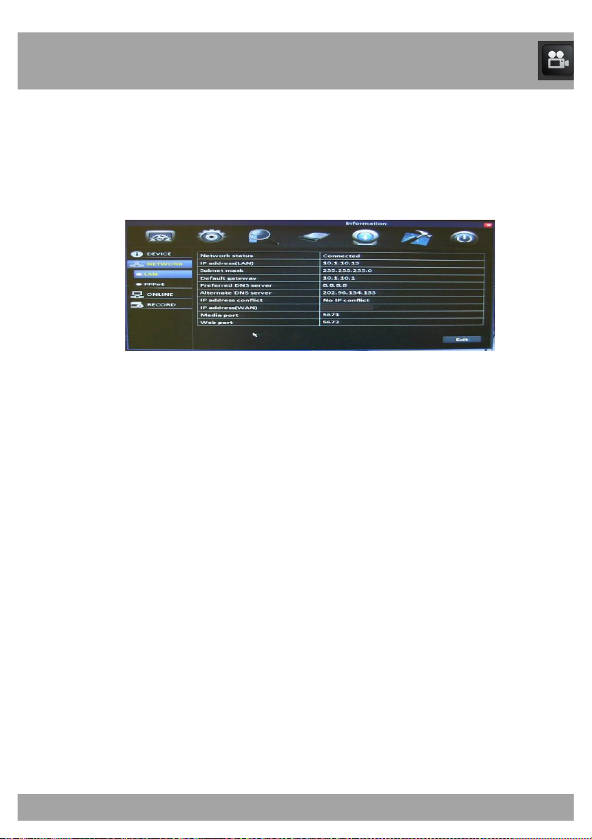
19.2.1 LAN Menu
The LAN Menu allows you to information about your Local Area Network
(LAN).
To access the LAN Menu, select the Information button, select Network,
and then select LAN.
• Network Status: Indicates whether the DVR is properly connected
to the internet.
• IP Address(LAN): The identification of the DVR when it is
connected to a network.
• Subnet Mask: This should always be set to 255.255.255.000. It
describes the range of IP addresses that can be found in the
network.
• Default Gateway: The connection between two networks. This
should be the router’s IP address.
• Preferred DNS Server: Primary Domain Name System. This will
vary from city to city.
• Alternate DNS Server: Secondary Domain Name System.
• IP Address Conflict: An IP address conflict will happen if two
devices on the same network have the same IP address.
• IP Address (WAN): The external IP address of the DVR.
• Media Port: Shows the port that you configured.
• Web Port: Shows the port that you configured.
Page 69
Chapter 19: Information Menu
69
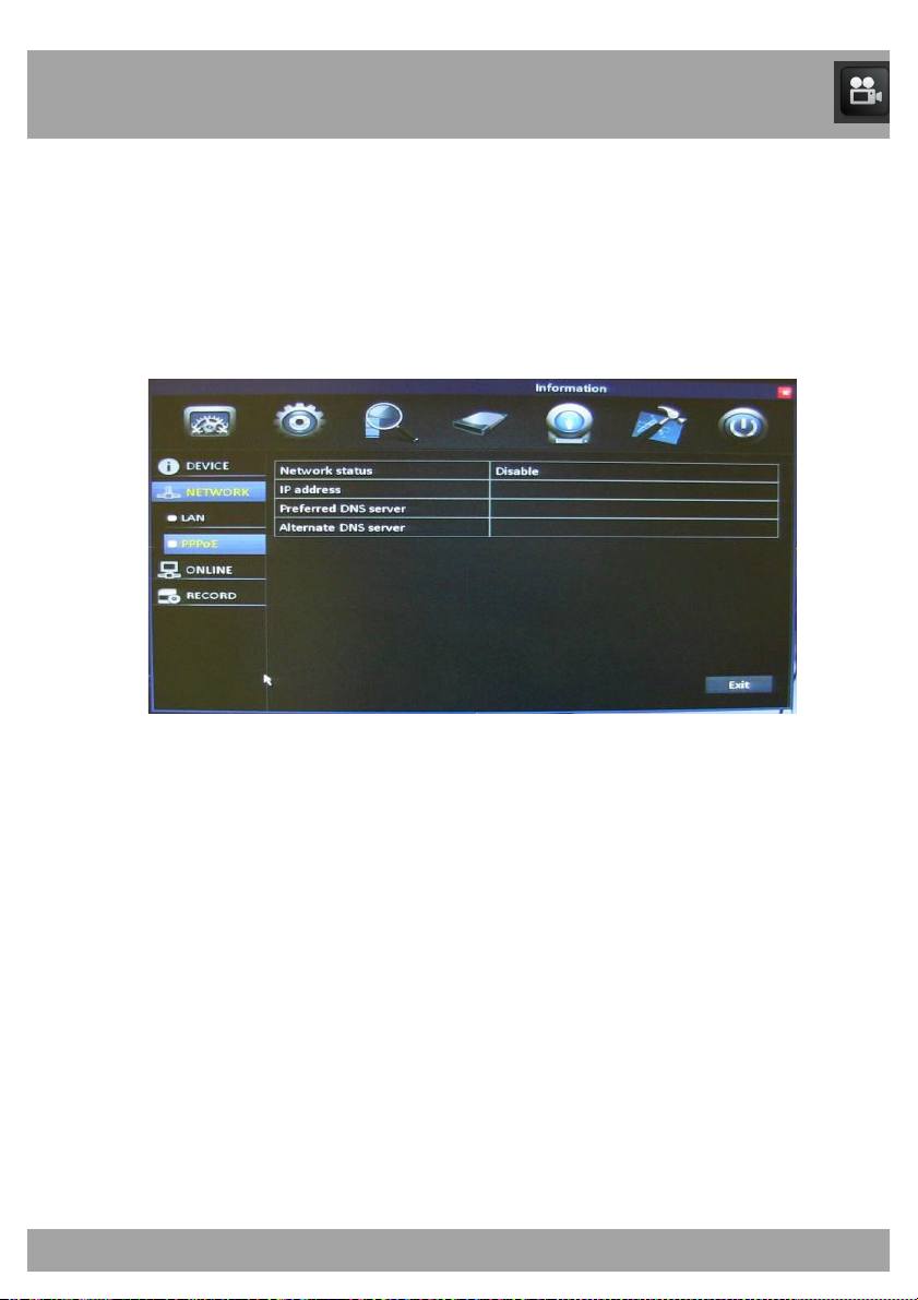
19.2.2 PPPoE Menu
The PPPoE (Point-to-Point Protocol over Ethernet) Menu allows you to
view information about your network.
To access the PPPoE Menu, select the Information button, select Network,
and then select PPPoE.
• Network Status: Shows whether the DVR is properly connected to
the internet.
• IP Address: The identification of the DVR when it is connected to a
network.
• Preferred DNS Server: Primary Domain Name System. This will
vary from city to city.
• Alternate DNS Server: Secondary Domain Name System.
Page 70
Chapter 19: Information Menu
70
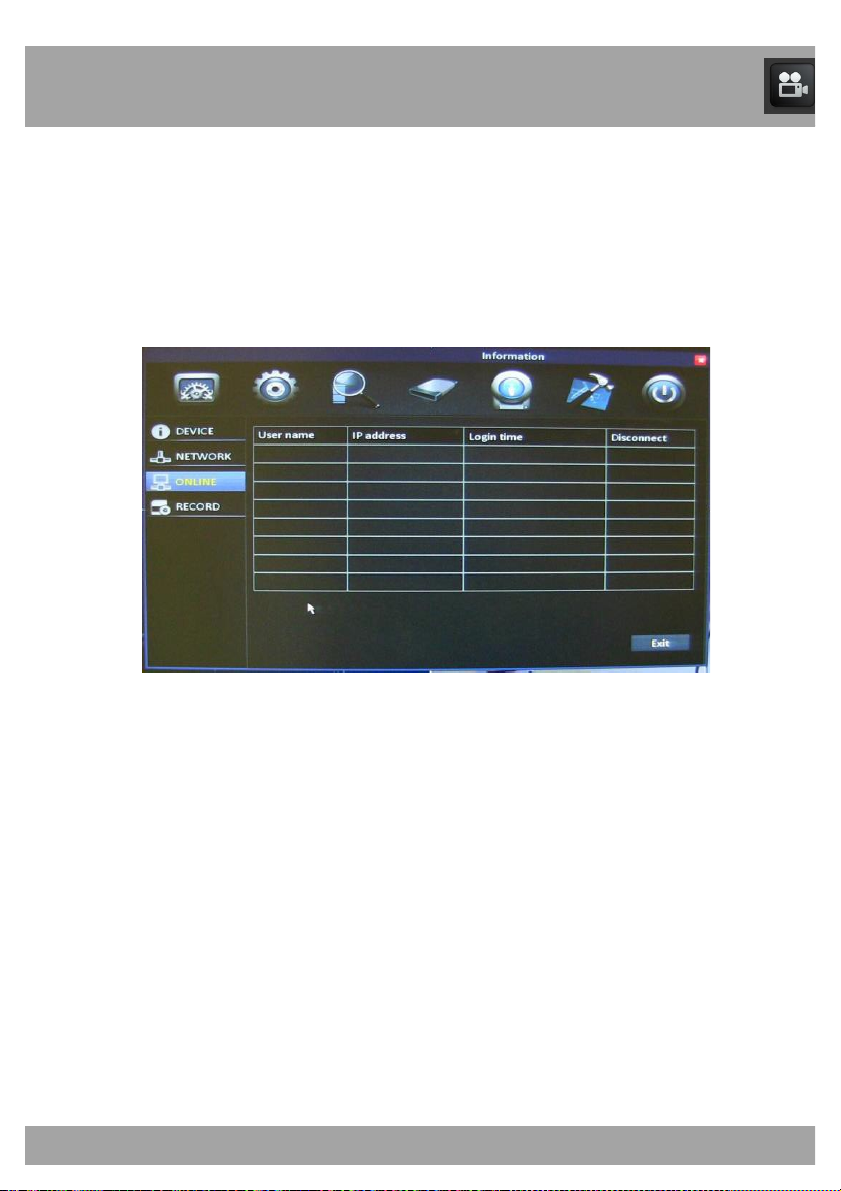
19.3 Online Menu
The Online Menu allows you to view the computers that are currently
connected to the DVR.
To access the Online Menu, select the Information button and then select
Online.
• User Name: The name of the computer that is accessing the DVR.
• IP Address: The identification of the device that is accessing the
DVR.
• Login Time: The time that the user logged in to the DVR.
• Disconnect: Allows you to disconnect the computer that is logged
in to the DVR.
Page 71
Chapter 19: Information Menu
71
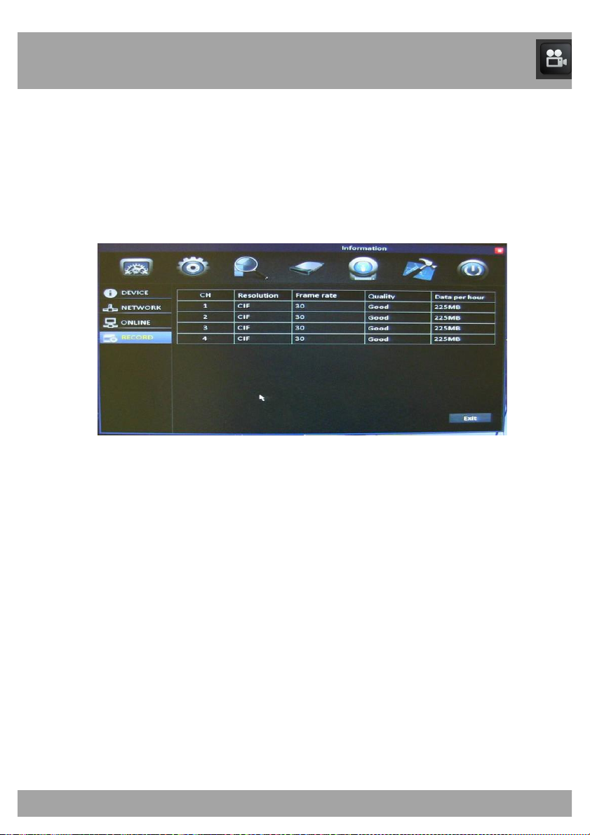
19.4 Record Menu
The Record Menu allows you to view the configured recording resolution of
the DVR.
To access the Record Menu, select the Information button and then select
Record.
• CH: Indicates the channel.
• Resolution: Shows the recording resolution of each channel.
• Frame Rate: Shows the frames per second of the channels when
recording.
• Quality: Shows the recording quality of each channel.
• Data per hour: Shows the amount of data per hour that will be
stored on the hard drive when recording at the settings that are
configured.
Page 72
Chapter 20: Maintenance Menu
72
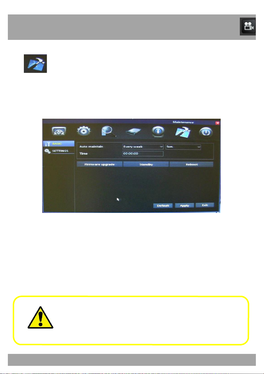
Maintenance Menu
Use this menu to access the Basic Maintenance Settings and Settings
menus.
Be sure to Apply all changes made to the menus. If you do not
apply the changes, they will not be saved.
You can also select the Default button on any page to restore the
DVR’s original settings.
Page 73
Chapter 20: Maintenance Menu
73
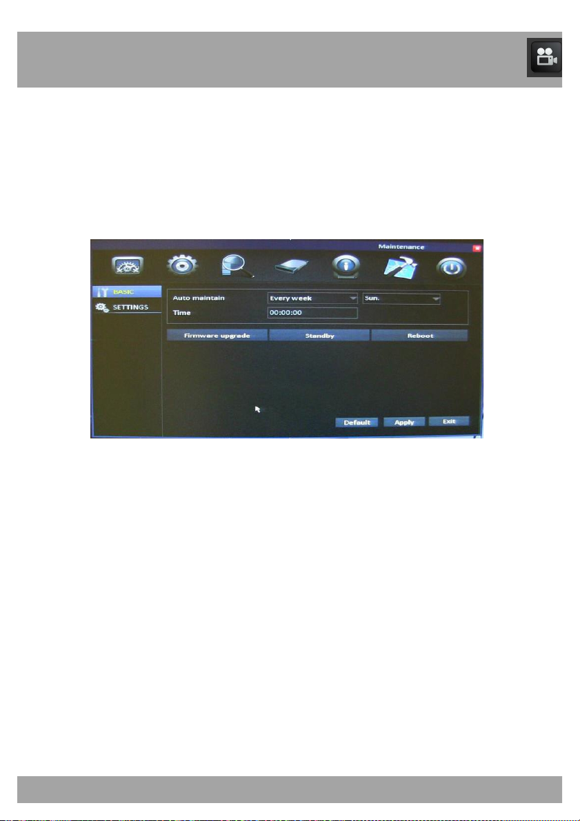
20.1 Basic Menu
The Basic Menu allows you to perform firmware upgrades and maintain the
DVR’s performance.
To access the Basic Menu, select the Maintenance button and then select
Basic.
• Auto Maintain: Allows you to choose when you would like your
system to automatically reboot. The DVR will reboot automatically
on a specified schedule to help prevent system and hard drive
failure and to preserve the life your DVR.
• Time: Allows you to choose a time when you would like the DVR to
reboot. Keep in mind that the DVR is set to military (24-hour) time.
• Firmware Upgrade: Performs a firmware upgrade from a USB
flash drive.
• Standby: Puts the DVR into standby mode.
• Reboot: Restarts the DVR.
Page 74

Chapter 20: Maintenance Menu
74
20.1.1 Firmware Upgrade
Your system will periodically need a firmware upgrade to ensure optimal
performance. Visit www.NightOwlSP.com to see if upgrades are available
for your system.
To upgrade firmware:
1. Download and save the latest firmware upgrade for your system
from www.NightOwlSP.com to your desktop.
2. Once you have saved the firmware to your computer, insert an
empty USB flash drive into the computer.
3. Locate the file you just saved to your desktop and open the folder.
4. This folder will contain a folder titled dvrupgrade and a Word
document with instructions.
5. Drag the folder labeled dvrupgrade to the empty USB flash drive.
6. Safely remove the USB flash drive from your computer.
7. Connect the USB flash drive to the USB port on the back of your
DVR.
8. Select the Maintenance button and then select Basic.
9. Select Firmware Upgrade. The DVR will automatically scan the
USB flash drive and begin upgrading the firmware. Do not remove
the USB flash drive while the upgrade is taking place.
10. A window will pop up, telling you not to power off the DVR. The
DVR will automatically install the upgrade and restart.
Page 75
Chapter 20: Maintenance Menu
75
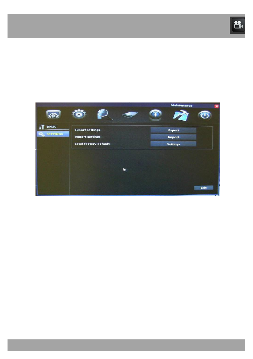
20.2 Settings Menu
The Settings Menu allows you to import or export the DVR’s settings.
To access the Settings Menu, select the Maintenance button and then
select Settings.
• Export Settings: Allows you to copy all of the settings on the DVR
to a flash drive.
• Import Settings: Allow you download all of the settings from a
flash drive to the DVR.
• Load Factory Default: Allows you to set the default settings for the
entire DVR.
Page 76
76
Chapter 21: Remote Access
This chapter will show you how to connect your DVR to the internet. You
will learn how to properly connect your DVR to your router/modem and set
up port configurations, internet configurations, Mobile configurations, and
DDNS registration.
You will need to have the following in
order to be able to successfully connect
the DVR to the internet.
• High-speed internet connection (at least 512K of bandwidth,
download and upload speeds)
• Router or modem with two open Ethernet ports
• Computer with Internet Explorer 7, 8, 9, or 10
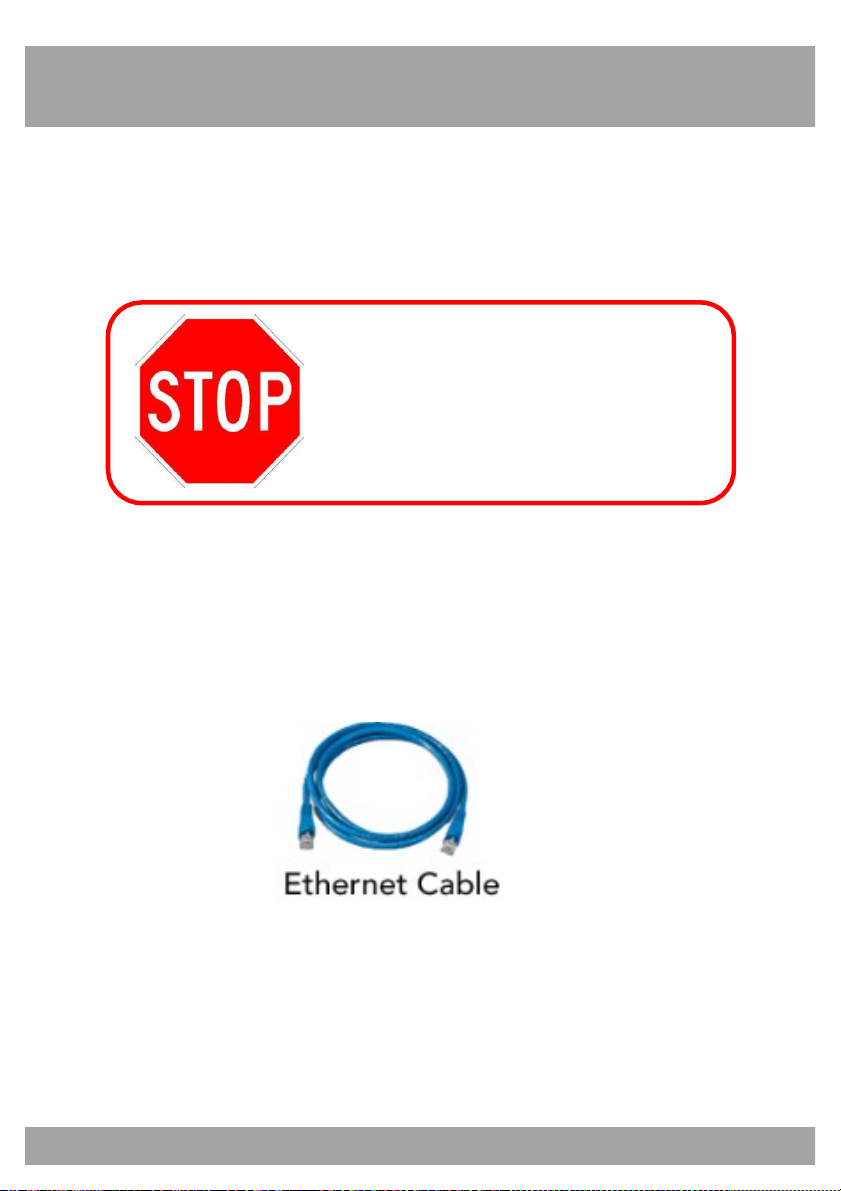
• Ethernet cable (included with the system; see image below)
• Second Ethernet cable to connect your computer to the
router/modem
Page 77
77
Chapter 21: Remote Access
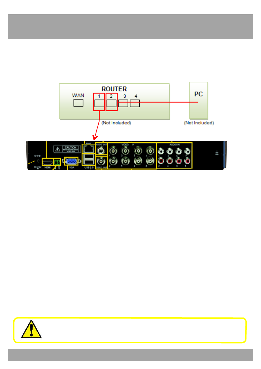
21.1 Connecting the DVR and Router/Modem
Use this section to learn how to connect the DVR to your router/modem.
DVR
1. Make sure that your DVR is connected to a power outlet.
2. Connect the DVR directly to the router through an open Ethernet
port with the included Ethernet cable.
3. Connect a computer directly to the same router through another
open port with an Ethernet cable.
Do not connect the DVR to a wireless router.
Page 78
78
Chapter 21: Remote Access
21.2 Windows Network Configuration
In this section you will determine basic information about your network
Make sure that the DVR is properly connected to the router/modem and
that you have a Windows computer connected to the same router.
Follow these steps to determine the basic information about your network:
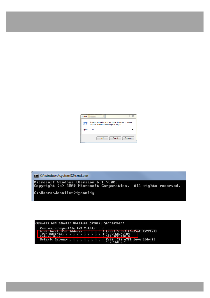
1. Press the Windows key and the R key at the same time on your
computer’s keyboard. Type cmd and press the Enter key.
2. In the command prompt window, type ipconfig and press Enter.
Find the section called “Ethernet adapter Local Area Connection” or
“Wireless LAN Adapter Wireless Network Connection.”
3. Find the IPv4 Address (it may be named “IP Address” in some
versions of Windows). Write down this number.
Page 79
79
Chapter 21: Remote Access
4. Change the last three digits to 150. You will need this new number
in a later step. (Example: Say you wrote down the IP Address
192.168.0.104. When the last digits are changed, the IP address
will be 192.168.0.150.)
5. Write down this number. You will use this number as the IP address
of your DVR in the next section.
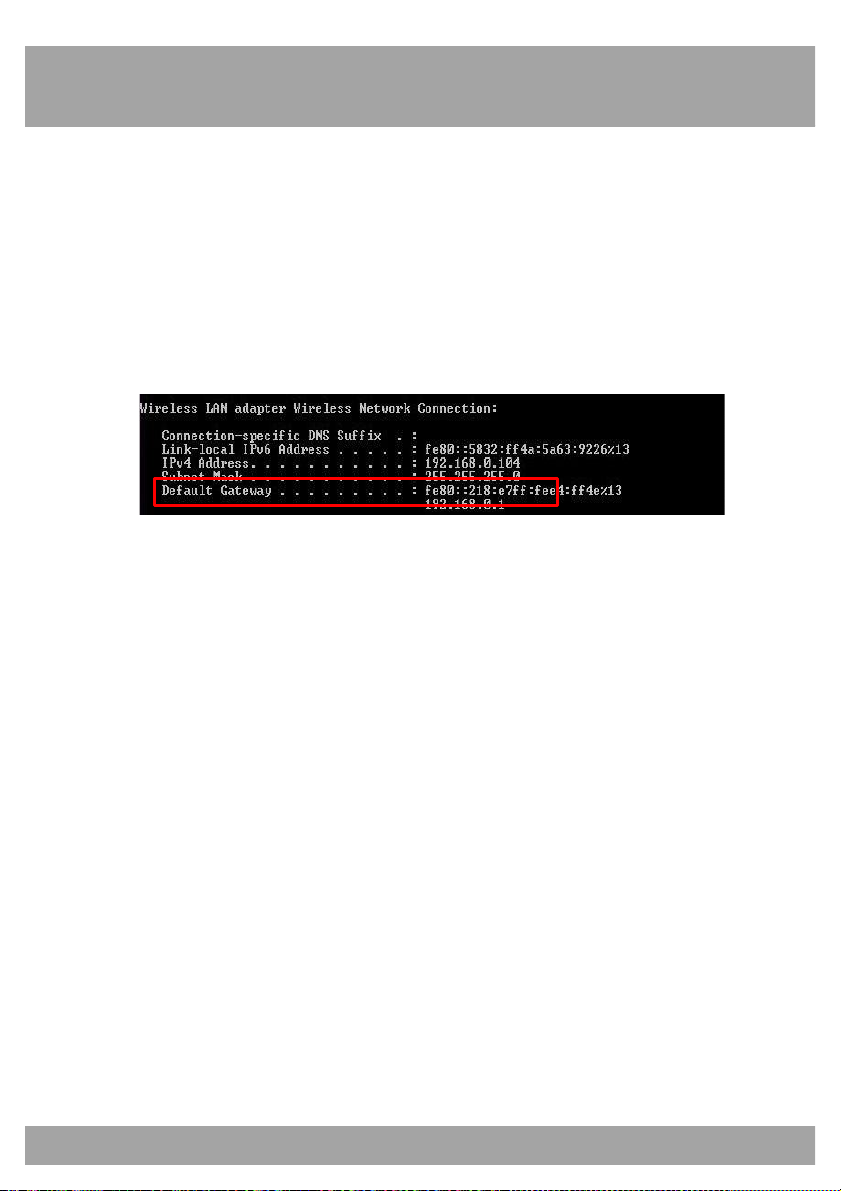
6. Find the Default Gateway.
7. Write down the Default Gateway number. This is the IP address of
your router. You will need to enter this in the DVR’s network
settings in the next section.
Page 80
Chapter 21: Remote Access
80
Changing the Network Settings on the DVR
For the following steps, use the information that you just wrote down.
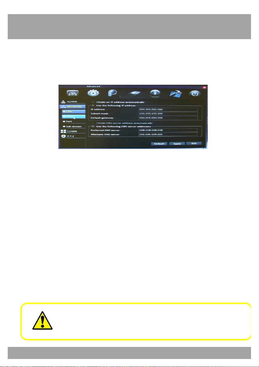
To access the LAN Menu, select the Advanced button, select
Network from the list on the left side of the screen, and then LAN.
• You can manually enter the IP address/DNS server information into
the DVR by selecting Use the following IP address.
• IP Address: Change this to the IP Address that you wrote down in
the previous section. You will have to enter a zero in front of any
numbers that do not have three digits. (Using the example from the
last section, the address would be 192.168.000.150 after the
necessary zeros are added.)
• Subnet Mask: This should be set to 255.255.255.000.
• Default Gateway: Change this to the router’s IP Address (Default
Gateway) that you wrote down in the previous section. You will
have to enter a zero in front of any numbers that do not have three
digits.
• DNS1: This will be filled in automatically.
• DNS2: This will be filled in automatically.
Write this information on the Information Log at the end of the
manual. Be sure to select Apply and restart the DVR to save all
changes.
Page 81

Chapter 21: Remote Access
81
21.3 Apple (Mac) Network Configuration
Follow the steps in this section to configure remote access for an Apple
Macintosh computer.
Make sure that the DVR is properly connected to the router/modem and
that you have a Macintosh computer connected to the same router/modem.
Follow these steps to determine basic information about your network:
1. Select the Airport icon on your computer screen.
2. Select the Open Network Preferences option.
3. Select Ethernet (wired).
4. Select the Advanced button in the lower right corner.
5. Select the TCP/IP tab at the top to display your computer's network
information.
6. Make note of your IPv4 Address.
7. Change the last digits to 150. (Example: Say you wrote down the IP
Address 192.168.0.104. When the last digits are changed, the IP
address will be 192.168.0.150.)
8. Write down this number. You will use this number as the IP address
of your DVR in the next section.
8. Make note of the IP address listed for Router. This is the IP address
of your router. You will need to enter this in the DVR’s Network
settings.
Page 82
Chapter 21: Remote Access
82
Use the information that you just wrote down for the next steps.
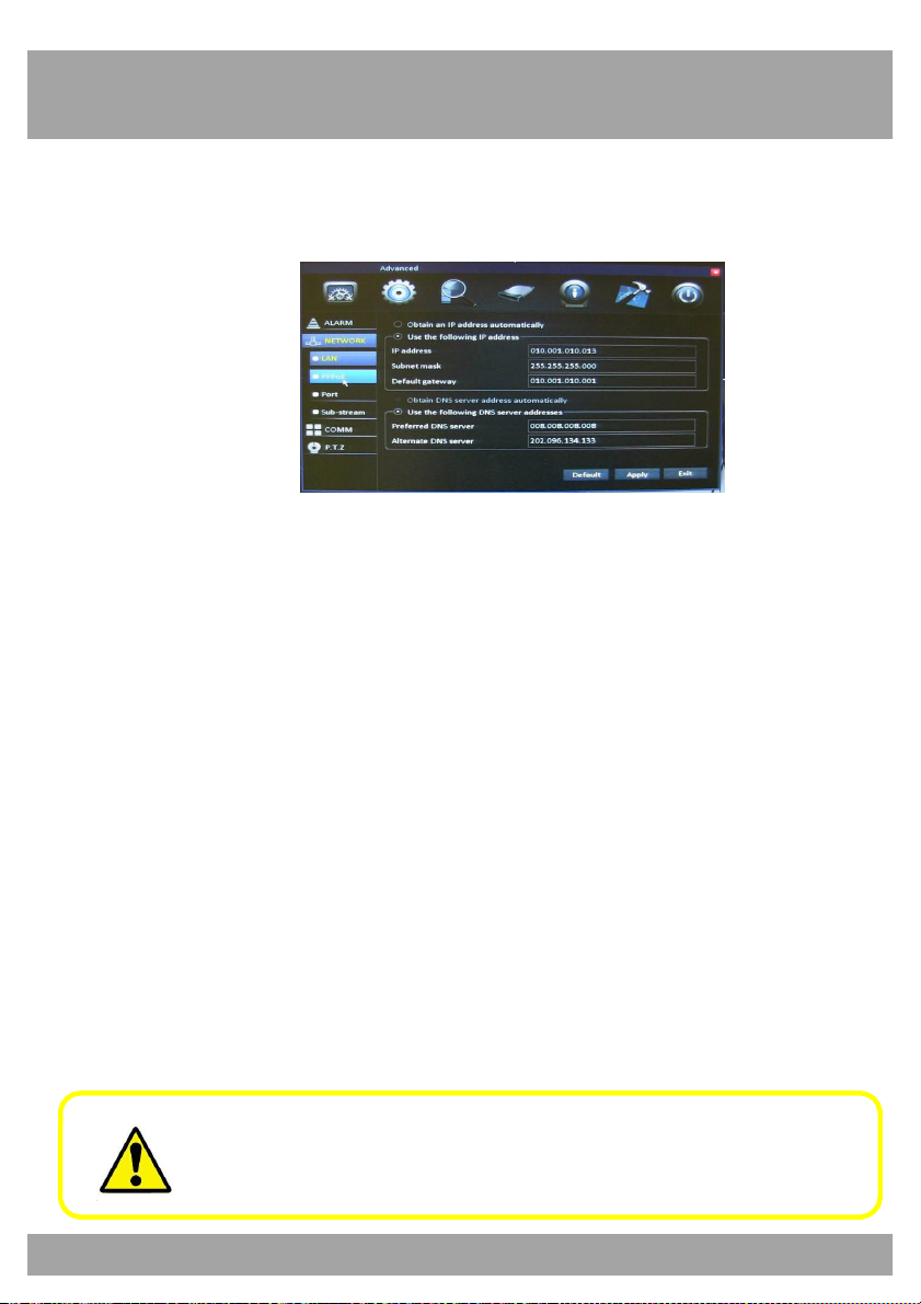
To access the LAN Menu select Advanced button, select Network from the
list on the left side of the screen, and then select the LAN tab.
• You can manually enter the IP address/DNS server information into
the DVR by selecting Use the following IP address.
• IP Address: Change this to the IP Address that you wrote down in
the previous section. You will have to enter a zero in front of any
numbers that do not have three digits. (Using the example from the
last section, the address would be 192.168.000.150 after the
necessary zeros are added.)
• Subnet Mask: This should be set to 255.255.255.000.
• Default Gateway: Change this to the router’s IP Address (Default
Gateway) that you wrote down in the previous section. You will
have to enter a zero in front of any numbers that do not have three
digits.
• DNS1: This will be filled in automatically.
• DNS2: This will be filled in automatically.
Write this information on the Information Log at the end of the
manual. Be sure to select Apply and restart the DVR to save all
changes.
Page 83
Chapter 21: Remote Access
83
After you have configured the Network Settings, you will need to forward
the necessary ports to be able to view the DVR over the Internet from
anywhere in the world.
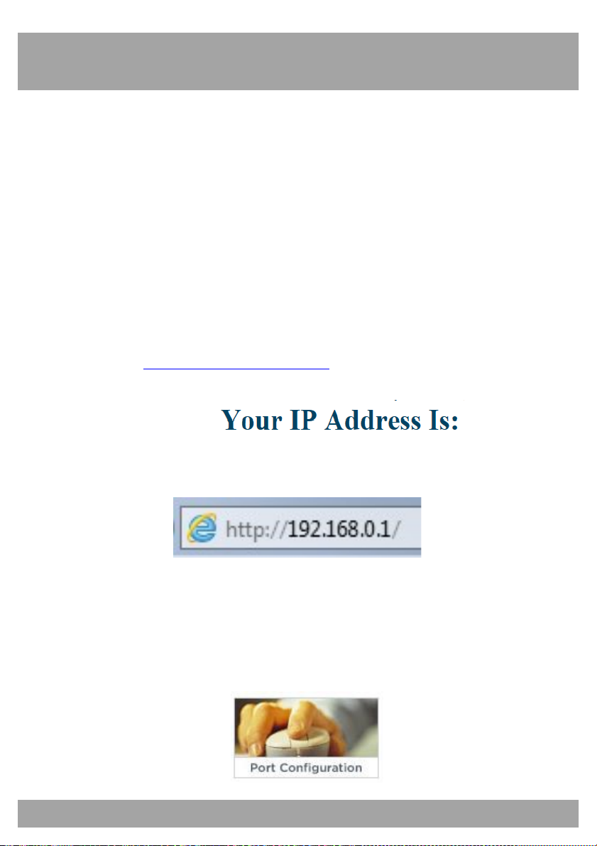
Refer to your router’s documentation to see how port forwarding works for
that device. This process may be called the Port Forwarding, Port Mapping,
or Virtual Server.
Below are some general considerations to keep in mind to make sure that
the appropriate ports are forwarded:
1. Go to http://www.whatismyip.com. Your IP address will appear at
the top of the page. This is your public IP address.
2. Open the Internet Explorer browser, enter http://youripaddress and
then press Enter.
3. Log in into your router using your user name and password.
(Contact your Internet Service Provider if you are unsure about the
login information.)
4. Once you have logged in to your router, go to the section indicated
to forward your ports.
Page 84
84
Chapter 22: Port Forwarding
Chapter 21: Remote Access
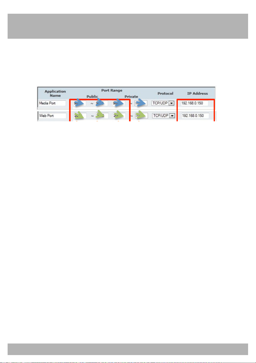
5. You will need to enter a new port forwarding entry for each port that
your DVR uses: Media Port (9000), Web Port (2051). Repeat the
steps below for each entry.
6. When entering the port numbers and IP address into your router’s
port forwarding section, you will need to do away with the leading
zeros (e.g., 09000 becomes 9000, 192.168.000.150 becomes
192.168.0.150, and so on).
7. In the port forwarding section o
asked to enter the following information in order to forward a port
(keep in mind that the wording may be different, depending on the
model of your router):
a. Application Name: This can be anything you choose.
b. Public Port: This should be set to one of the three ports
you need to forward: Media Port (9000), Web Port (2051),
or Server Port (2050).
c. Private Port: This should be set to the same number you
entered for the Public Port.
d. Port Type/Protocol: If your router has an option for both,
use TCP and UDP. If your router allows either TCP or UDP
port types, use TCP.
e. Host IP Address: This should be set to the IP address you
configured for your DVR earlier.
f your router, you will typically be
Page 85
Chapter 22: Port Forwarding
85
22.1 Checking the Ports After Port Forwarding
Once you have forwarded the necessary ports on your router, you should
check to make sure they have been correctly forwarded.
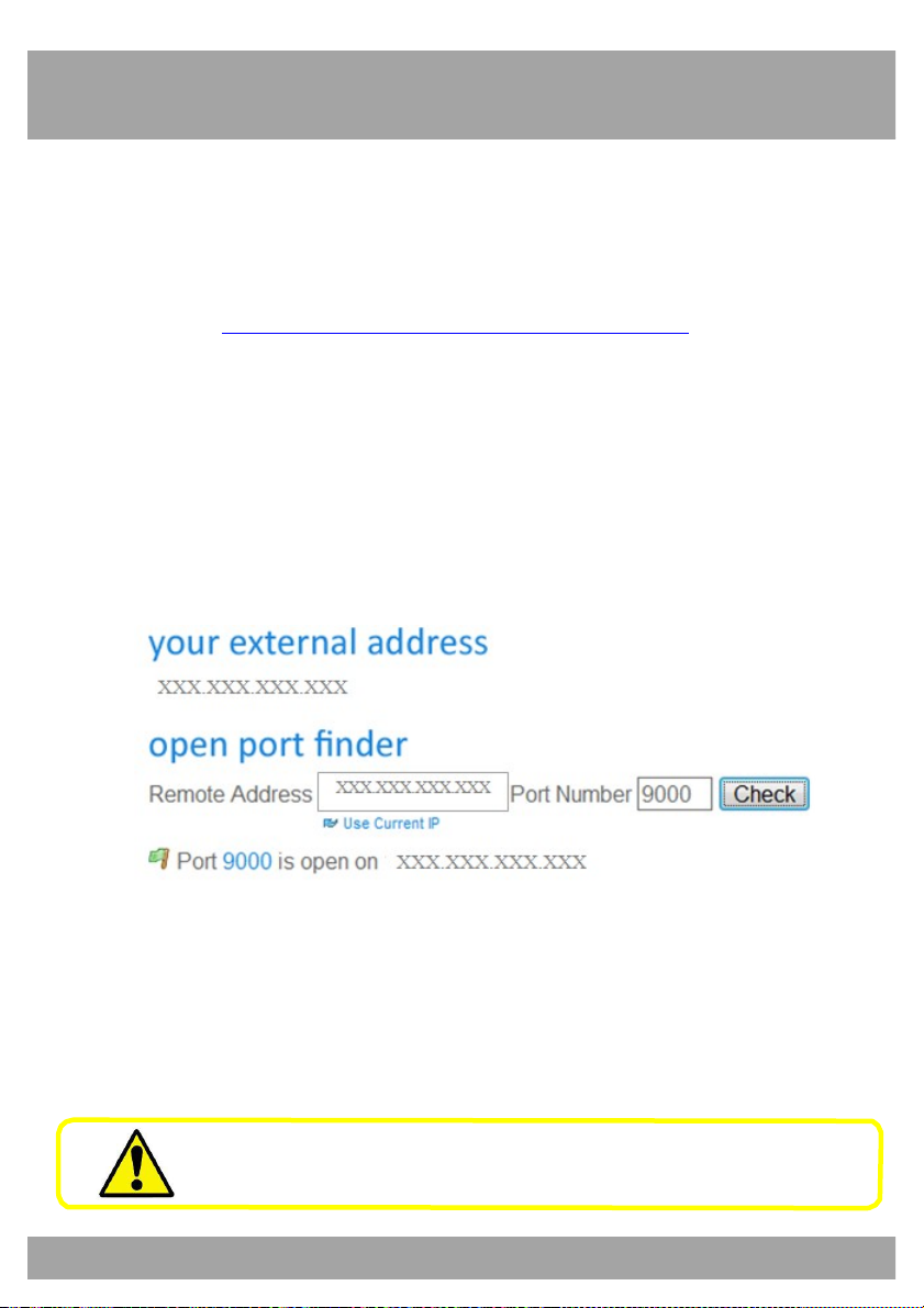
1. Go to http://www.yougetsignal.com/tools/open-ports/.
2. Type in port 9000 and select the Check button to see if the port
tests as open or closed.
3. Type in port 2051 and select the Check button to see if the port
tests as open or closed.
4. All ports should be open, as shown in the example below.
5. If any port tests as closed, that port is not forwarded correctly.
Write “your external address” in the Information Log at the end of
the manual.
Page 86
Chapter 23: DDNS Registration
86
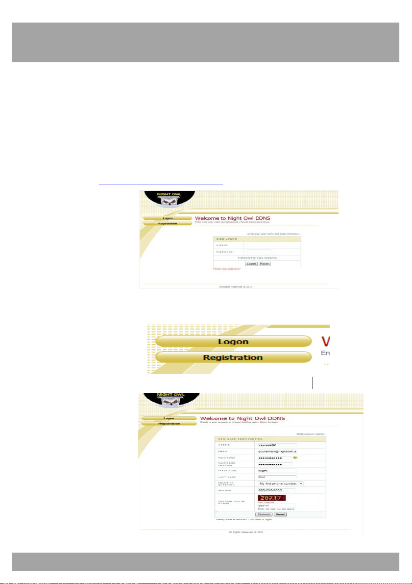
23.1 Registering a Free Domain Name (DDNS)
This option allows you to set up a free website address that will point back
to the DVR regardless of whether the IP Address changes. If you do not
have a static IP Address, you should use this option.
Follow the steps below to register a free domain name (DDNS)
1. Go to http://www.nightowldvr.com.
2. Select the Registration button located at the top left corner of the
page.
3. Complete the New User Registration form.
Page 87
87
Chapter 23: DDNS Registration
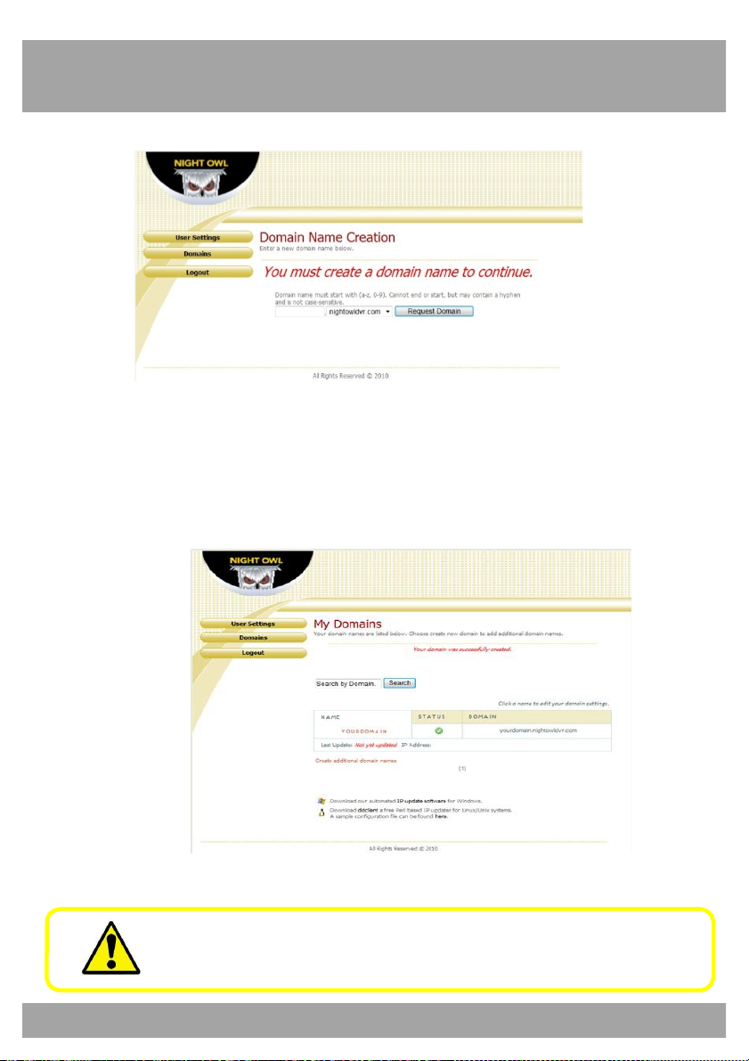
4. Create a domain name.
5. If the domain name that you have chosen is available, you will see
a window that tells you that your domain was successfully created.
(If the domain name is taken, try again until you find an available
name.)
Write this information in the Information Log at the end of the
manual.
Page 88
88
Chapter 23: DDNS Registration
23.2 Adding your New Domain Name to your DVR
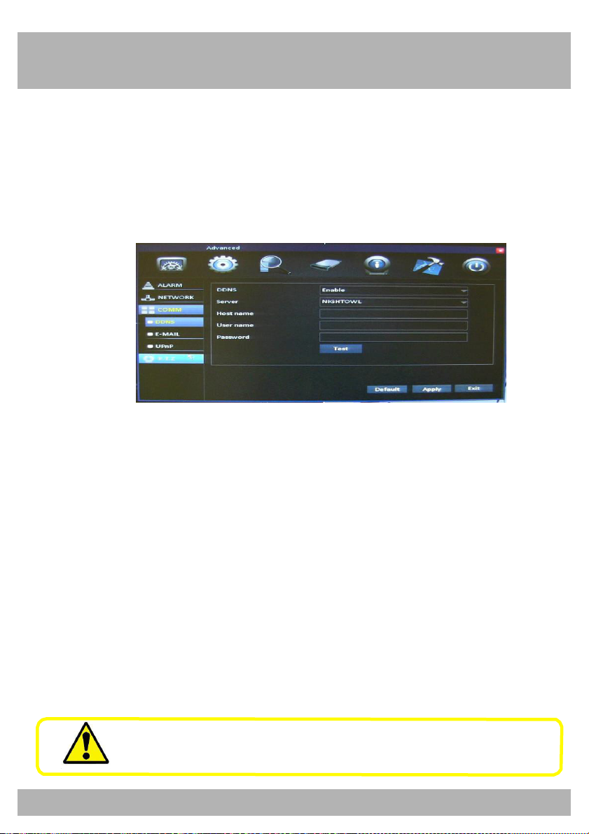
Use the DDNS Menu to configure DDNS setup after you have registered
for a free domain name.
To access the DDNS Menu, select the Advanced button, select COMM,
and then select DDNS from the list on the left side of the screen.
• DDNS: This should be set to Enable.
• Server: This should be set to NightOwl.
• Host Name: This should be set to the domain name that you
crea
ted during DDNS registration. An example is shown above.
• Username: Your user name is the UserID that you created during
DDNS registration. An example is shown above.
• Password: Your password is the password that you created during
DDNS registration.
• Test: Tests the settings to make sure they work correctly.
Be sure to Apply all the changes before selecting Test, or the
test will not work.
Page 89
89
Chapter 24: Internet Viewing
Use the Nightowl View or Control Management Software to access your
DVR remotely over the Internet or within your local area network. Make
sure that you have completed the steps in Chapters 21 and 22 of this
manual before trying to access the DVR using this software.
24.1 Setting ActiveX Controls
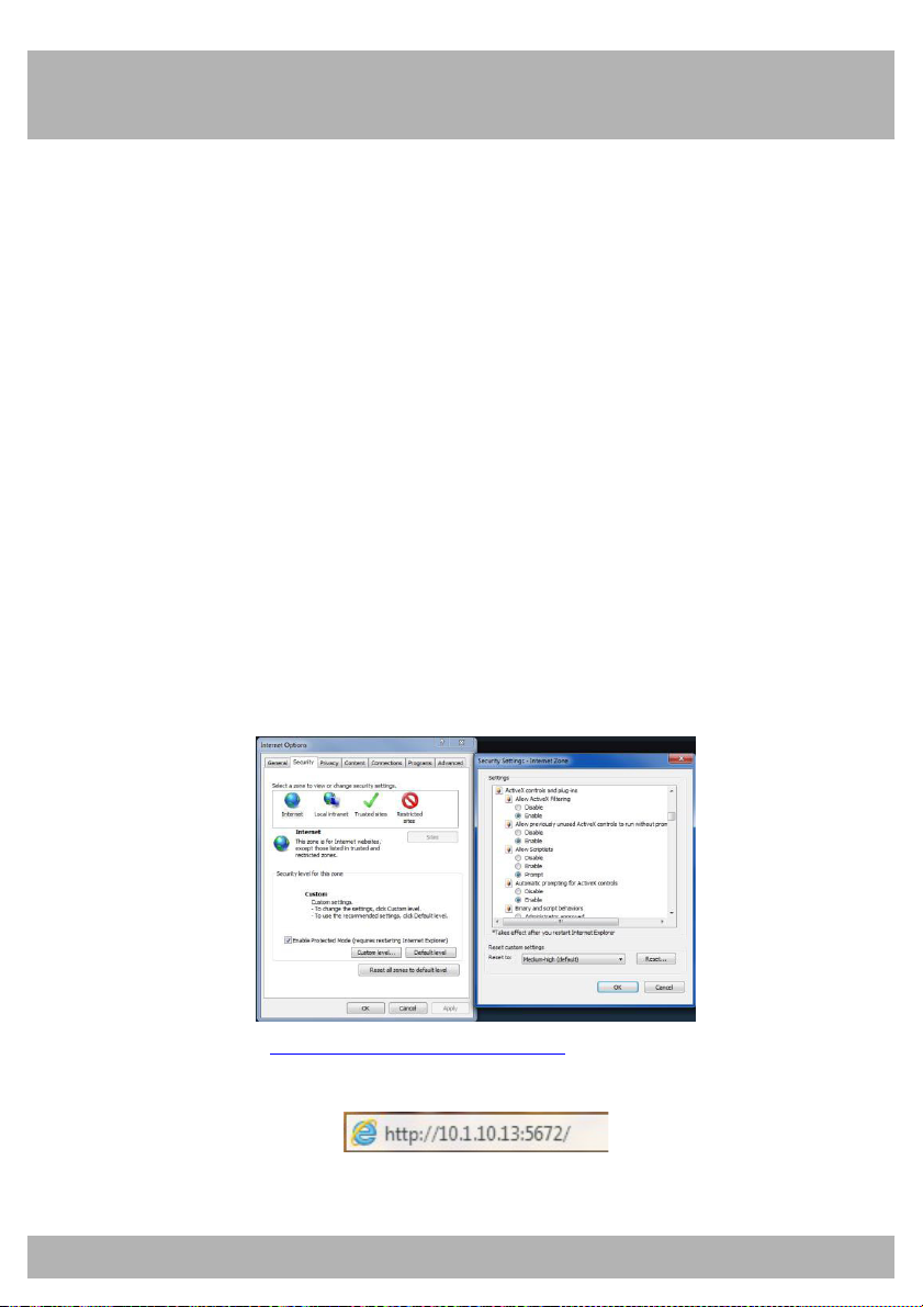
Before you can access the DVR using an Internet browser, you will need to
configure the ActiveX Controls. Follow the below
(Windows only).
1. Open the Internet Explorer browser.
2. Go to Tools (the gear icon) and select Internet Options.
3. Click the Security tab.
4. Select the Custom Level button.
5. Scroll down until you see ActiveX controls and plug-ins.
6. Set every setting to either Enable or Prompt.
7. Now enter http://youripaddress:webport to access your DVR
steps for configuration
through the Internet browser.
Page 90
Chapter 24: Internet Viewing
90
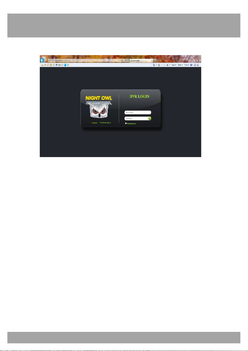
24.2 DVR Login
• User Name: Type in the user name that you created in the
Password Menu of the DVR.
• Password: Enter the password that was assigned to the User.
• Language: If you would like the information to be displayed in
another language, you can change it to English, French, or
Spanish.
• Remember Me: Check this box for the User Name to be saved on
the computer.
Page 91
Chapter 24: Internet Viewing
91
24.3 Using Nightowl View
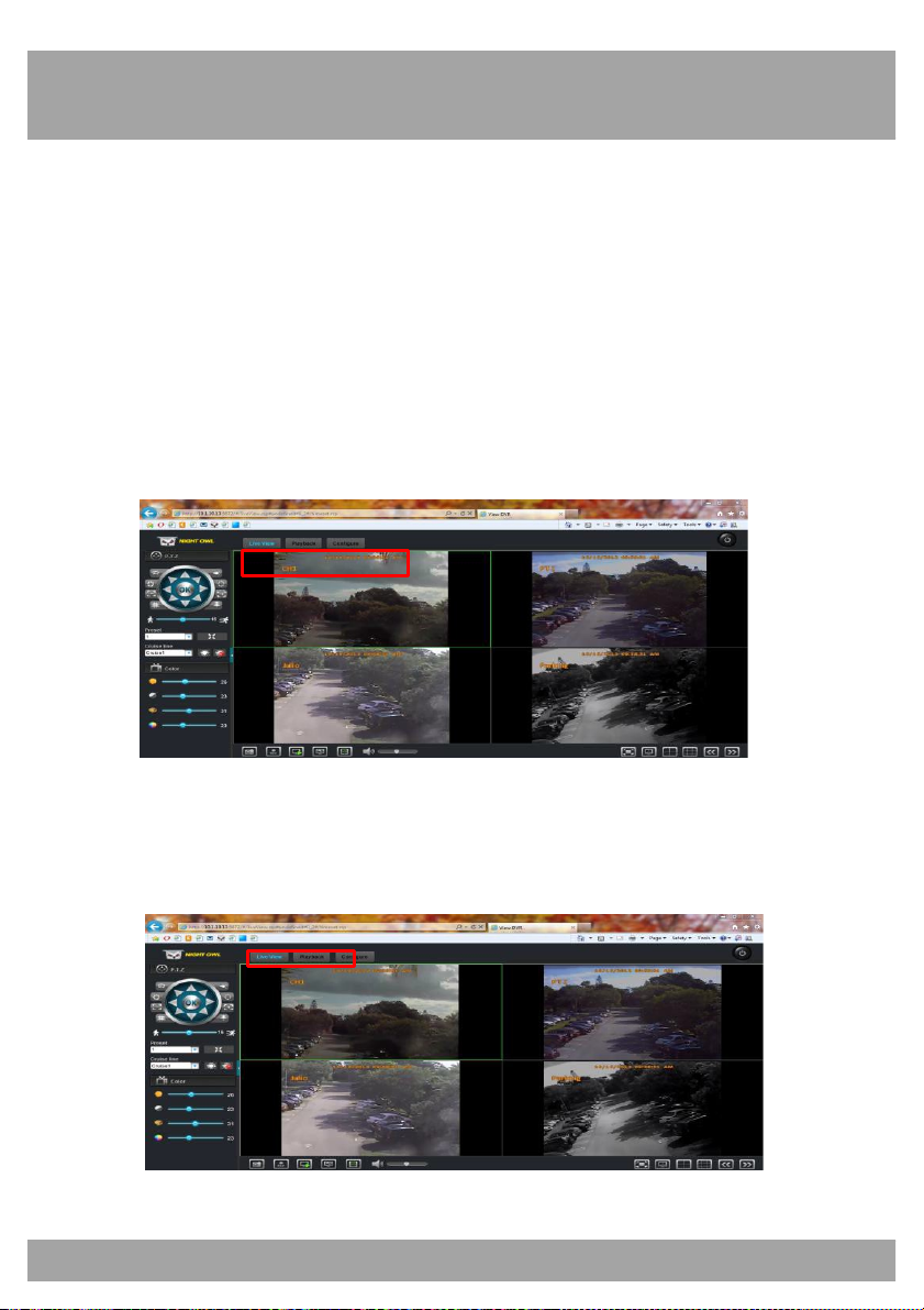
You can use Internet Explorer to access one or more DVRs. It allows you to
view live and recorded video over the internet.
Channel Information
The channel names, date, and time will be indicated on every channel in
real time.
Menu Bar
The Menu Bar gives you access to the Live Viewing, Playback, and
Configure settings.
Page 92
Chapter 24: Internet Viewing
92
!
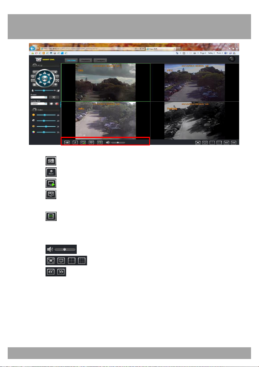
Play Control
• Takes a snapshot of the video.
• Starts/stops recording on all channels.
• Stops/plays the live video feed.
• Enables Main-Stream on all channels. This requires a fast
network for transmission.
• Enables Sub-Stream on all channels. This requires a normal
network for transmission and is the default for all channels. This
setting may display poor image quality.
• Adjusts the volume of any audio-enabled channels.
• Shows the different viewing options.
• Switches the viewing pages.
Page 93
Chapter 24: Internet Viewing
93
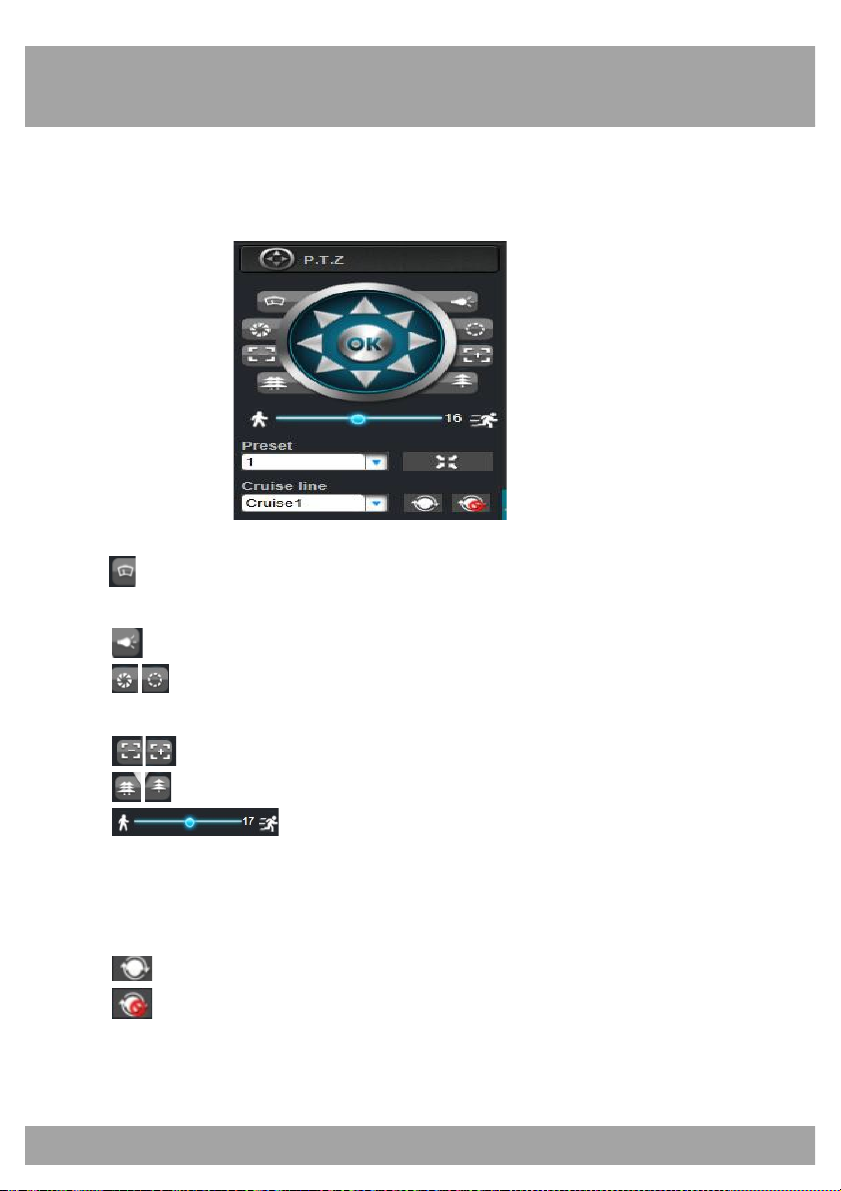
PTZ Control
These control settings can only be used for cameras that have Pan, Tilt,
and Zoom features. (A PTZ camera is not included.)
Arrows: Move the camera manually in the direction of the arrow.
Allows you to clean the camera lens if your camera has a wiper
function.
Allows you to fill in the light if your camera has this function.
Allows you to adjust the type of lens to get the best picture in
different lighting conditions.
Allows you to zoom the camera in and out.
Allows you to focus the camera.
Changes the speed of the camera when rotating.
Preset: Allows you to set PTZ preset positions.
Cruise Line: Allows you to set four points for the camera to move to;
the camera will follow these points during Cruise.
Starts PTZ cruise.
Stops PTZ cruise.
Page 94
Chapter 24: Internet Viewing
94
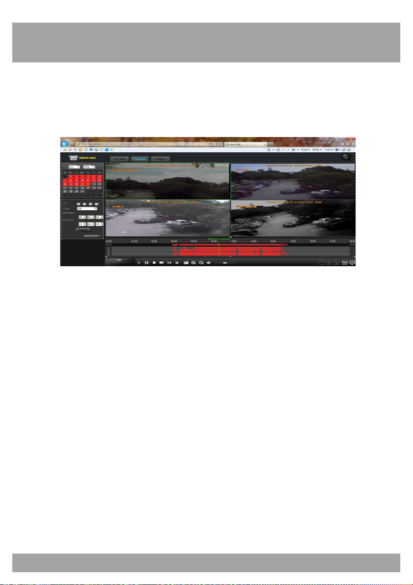
Playback
This screen lets you search, play back, and back up recorded videos.
To access this menu, select the Playback button from the Menu Bar.
• Calendar: Shows days with recordings in bold numbers. Select a
date to view a file list.
• Refresh: Refreshes the file list when a day is selected.
• Ch: Allows you to sort the file list by a particular channel.
• Type: Allows you to sort the file list by a particular type of recording
such as alarm (motion detection) and normal (continuous).
• Start Time: Allows you to begin the search at a certain time.
• End Time: Allows you to end the search at a certain time.
• Search: Searches the file list for the indicated channel and
recording type.
• Record List: Opens a submenu that lists all recordings for the
selected day. You can back up files from this function.
Page 95
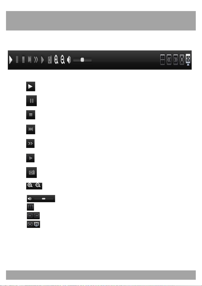
Chapter 24: Internet Viewing
95
Playback (continued)
Use the bottom control panel for various video controls.
Plays the video.
Pauses the video.
Stops the video.
Slows down the video.
Speeds up the video.
Shows each frame during playback.
Captures an image.
Allows you to configure the timeline to show hours.
Adjusts the volume on channels with audio.
Displays the screen as a quad view.
Allows you to switch between pages of videos.
Allows you to stretch the view of the channels across the entire
screen.
Page 96
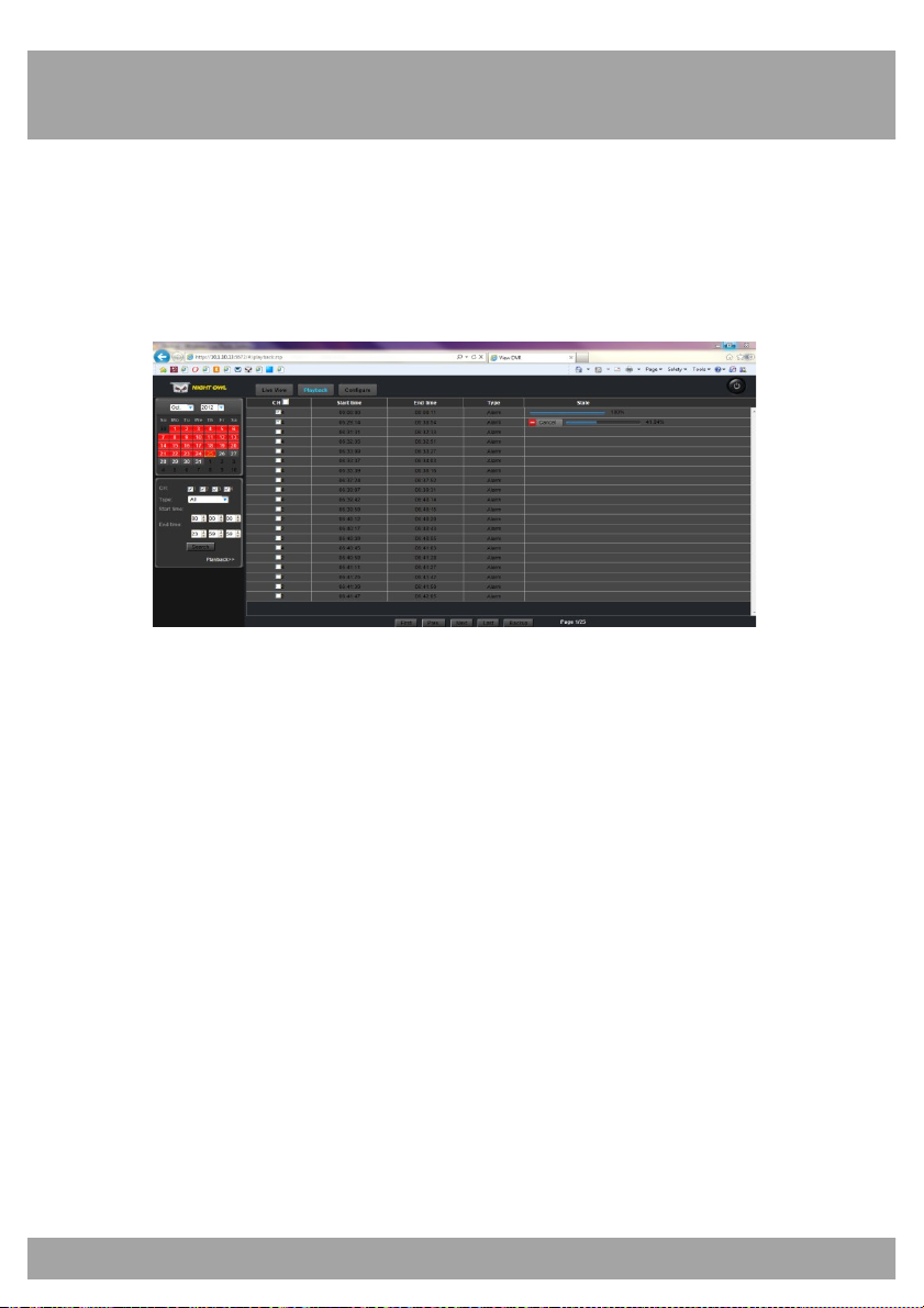
Chapter 24: Internet Viewing
96
Backup
This screen allows you to back up files to your computer.
To access this screen, select the Playback tab from the Menu Bar and
then select the Record List button on the left side of the screen.
• CH: Shows the channel that recorded the file.
• Start Time: Shows the time the recording started.
• End Time: Shows the time the recording ended.
• Type: Allows you to sort the file list by a particular type of recording
such as alarm (motion detection) or normal (continuous).
• State: Shows a status bar when backing up any file.
• First: Takes you to the first page of the list.
• Prev: Takes you to the previous page of the list.
• Next: Takes you to the next page of the list.
• Last: Takes you to the last page of the list.
• Backup: Copies all currently selected files (indicated by the
checkbox to the right of the file in the list) to your computer. Be sure
to go into the local settings and set the location that the files will be
saved to.
Page 97
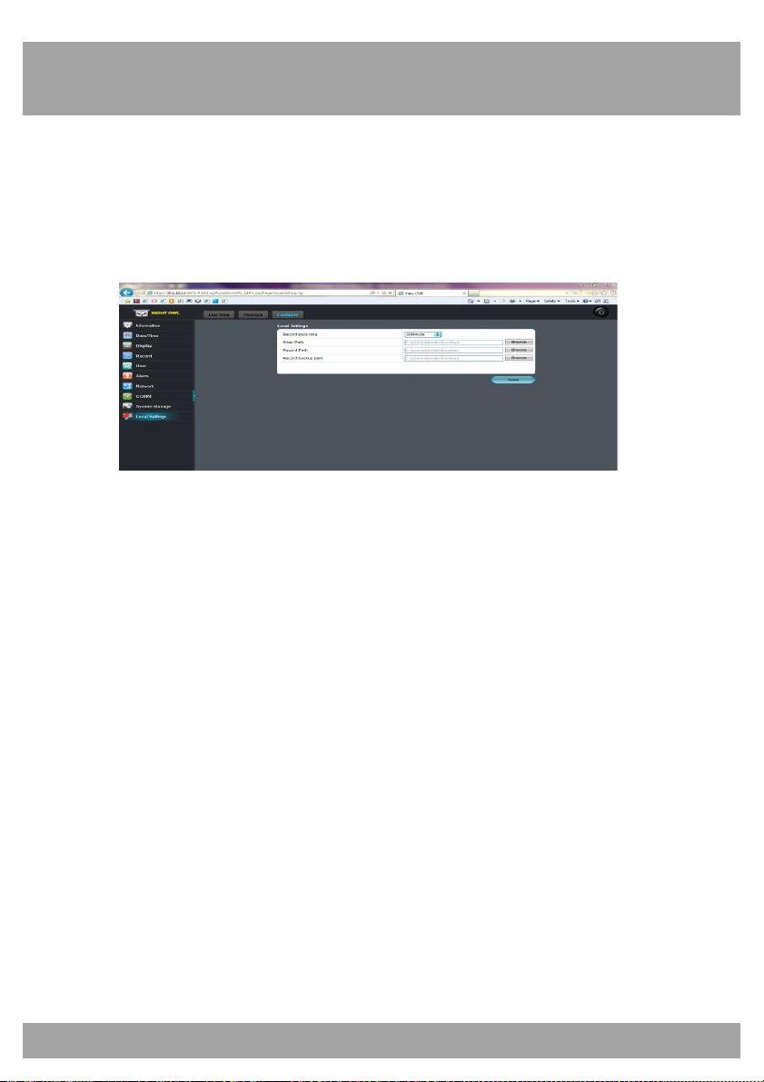
Chapter 24: Internet Viewing
97
Remote Setting
This screen allows you to access all of the DVR setting menus.
To access the Remote Setting screen, select the Remote Setting button
from the Menu Bar.
• Information: Refer to Chapter 19 of this guide for details.
• Date/Time: Refer to Chapter 14.2 for details on configuration.
• Display: Refer to Chapter 14.3 for details on configuration.
• Record: Refer to Chapter 14.4 for details on configuration.
• User: Refer to Chapter 14.5 for details on configuration.
• Alarm: Refer to Chapter 15.1 for details on configuration.
• Network: Refer to Chapter 15.2 for details on configuration.
• COMM: Refer to Chapter 15.3 for details on configuration.
• System Manage: Refer to Chapter 18 for details on configuration.
• Local Settings: Allows you set the location the files will saved to.
Page 98
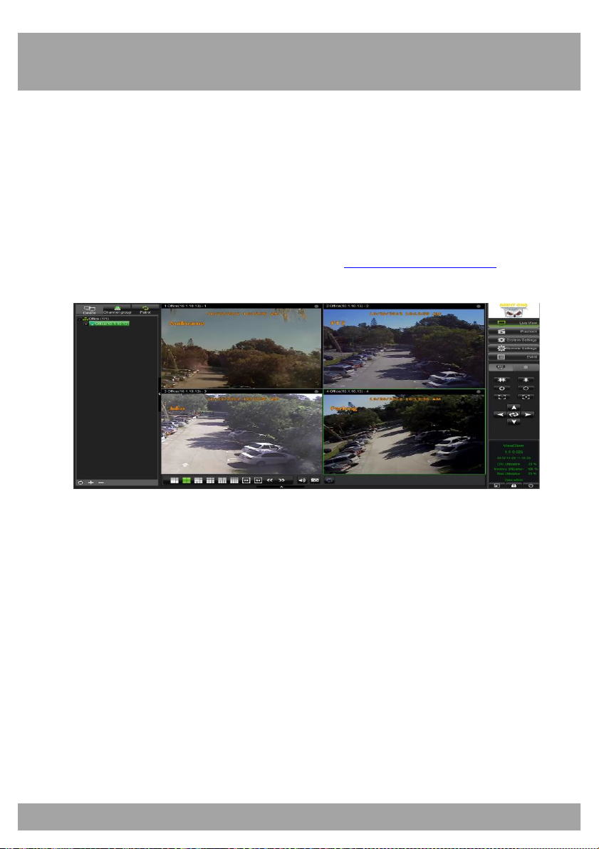
Chapter 24: Internet Viewing
98
24.4 Using Control Management Software (CMS – Nightowl View)
You can use the CMS software to access one or more DVRs remotely over
the Internet or within your local area network. Make sure that you have
completed the Remote Access chapter of this manual before trying to
access the DVR using this software.
The CMS software can be downloaded from www.NightOwlSP.com or from
the installation CD that was included with your DVR system.
Key Features of the CMS:
• Compatible with Windows XP, Vista, 7 & 8; Mac OS 10.6 and
above
• Three users can access the software on one computer
• Connect over 100 devices with 16 channels
• View up to 64 channels on one screen
• Configure DVR settings remotely
• PTZ controls
Page 99
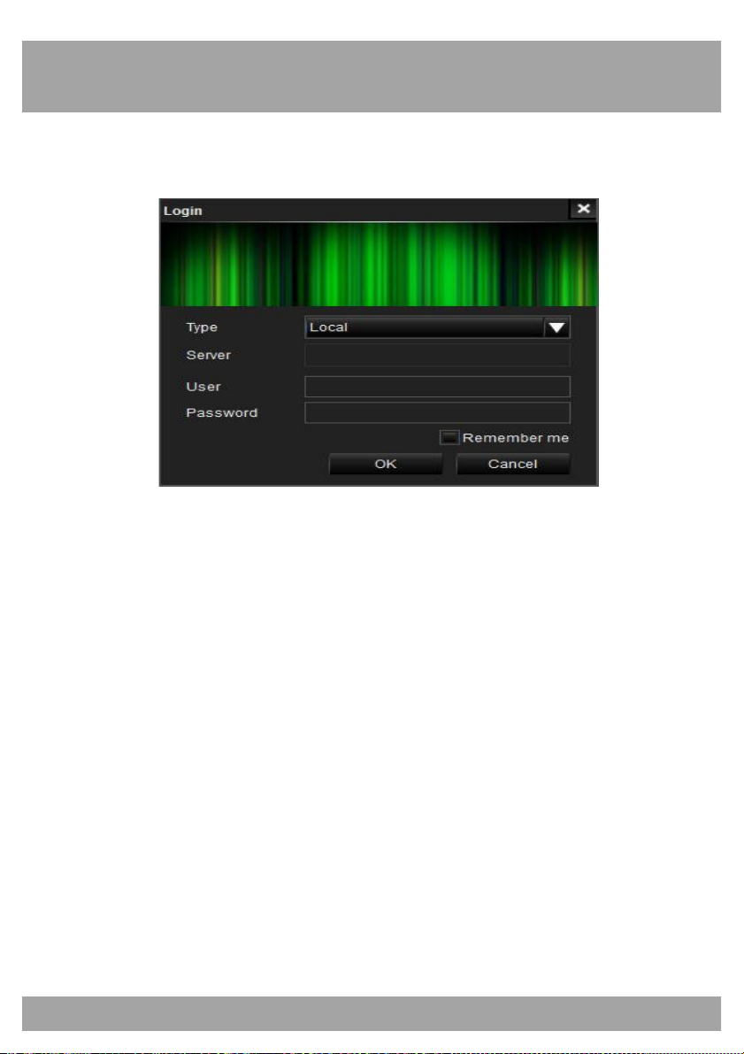
Chapter 24: Internet Viewing
99
Starting the CMS
You will have to register as an administrator when starting the CMS.
• Type: Choose between Local and Server. Local allows you to
configure DVRs. Server allows you to enter a server address. For
example, the Night Owl DDNS Server.
• Server: This will be left blank if you chose Local. If you chose
Server you will need to enter the name of the server, such as Night
Owl Server.
• User: The initial user will be admin if you chose Local. If you chose
Server, enter your UserID from the server that you set up.
• Password: The initial password should be left blank if you chose
Local. If you chose Server, enter your UserID Password from the
server that you set up.
Page 100
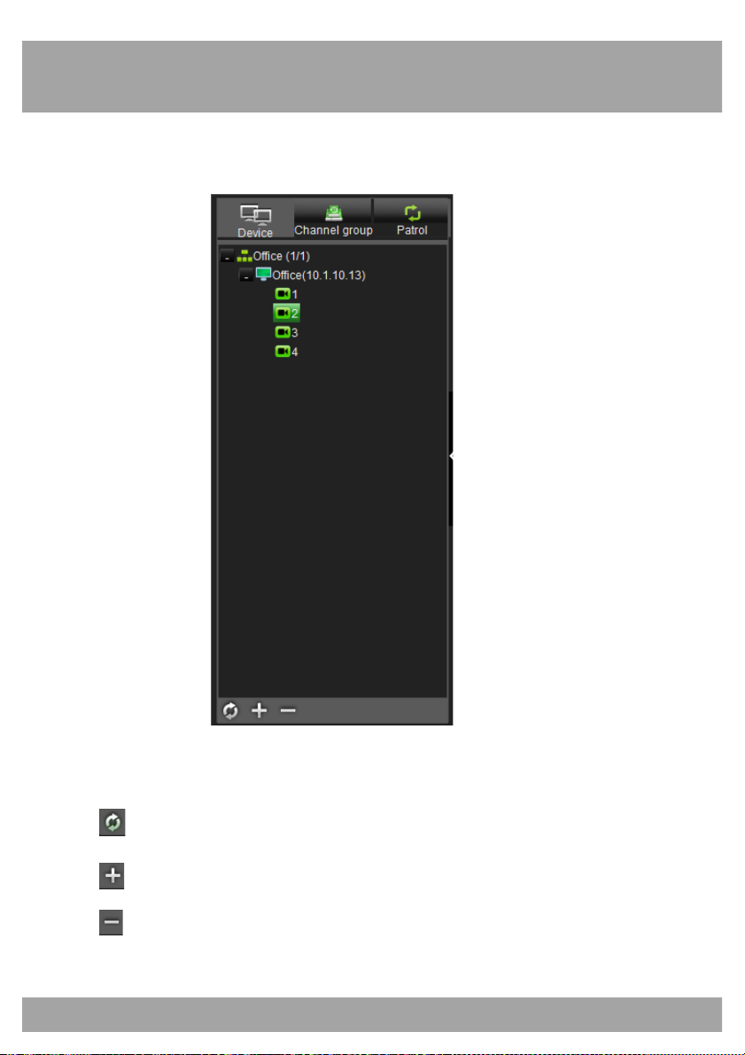
Chapter 24: Internet Viewing
100
Device List
This menu shows all DVRs that have been added to the CMS.
Device List: Lists all DVRs that have been added to the CMS.
Allows you to refresh devices.
Allows you to add groups.
Allows you to delete devices.
 Loading...