

Night Owl X100-DVR16-2TB User Manual
QUICK SETUP GUIDE
X SERIES SECURITY KITS
BEFORE YOU GET STARTED YOU WILL NEED
Included: Not included:
DVR with power adapter TV or monitor with HDMI, VGA or RCA input
Cameras with 60 ft. BNC cables, power splitters, and power adapter BNC-to-RCA cable (if TV or monitor does not have VGA input)
HDMI cable Computer with Windows® Vista, Windows® XP, Windows® 7, or Windows® 8
Ethernet (RJ45) cable Router/modem with at least 2 empty ports
USB mouse
D-Connector for audio (only included on certain models)
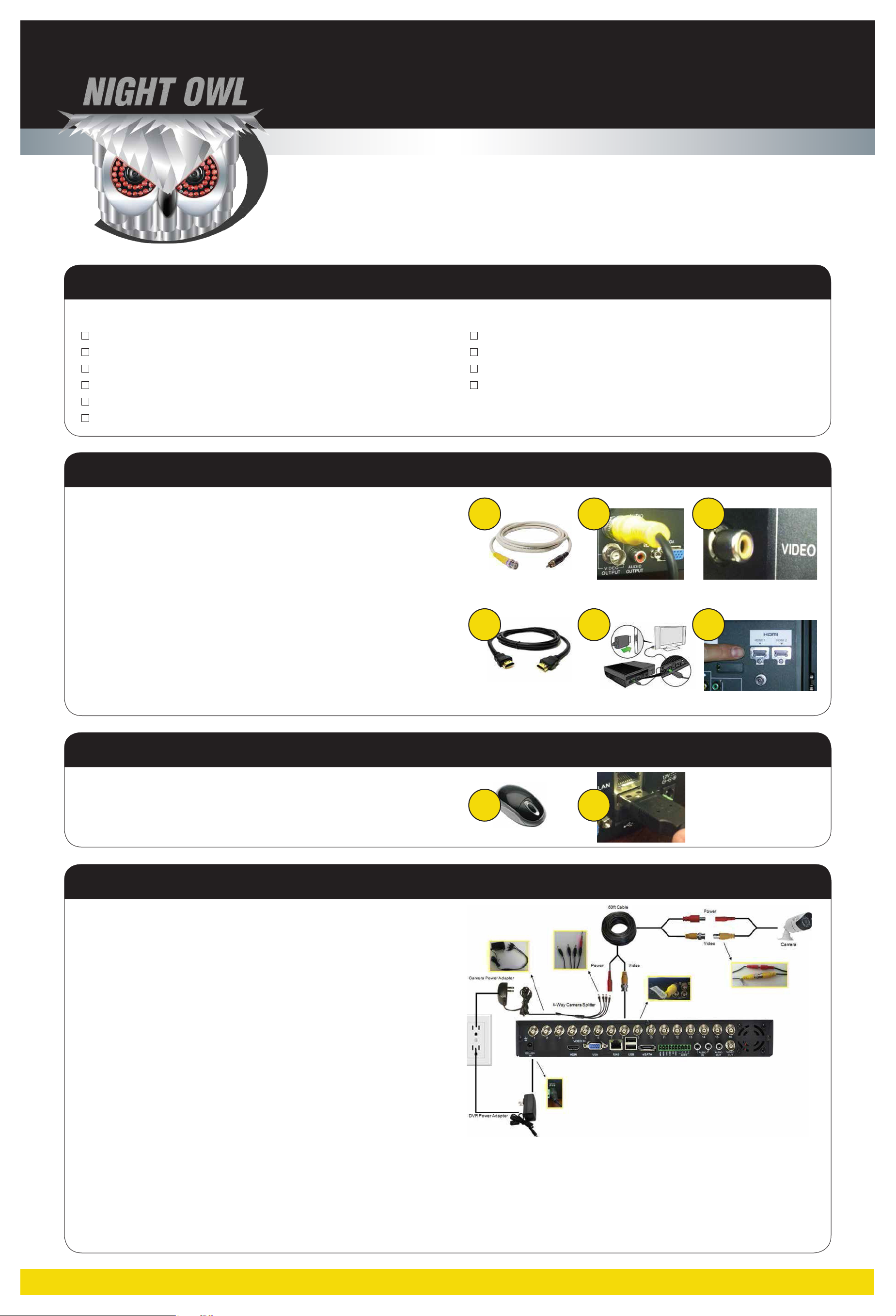
STEP 1: Connecting the DVR to a TV or monitor
If your TV or monitor has RCA inputs (and no VGA input), follow these steps:
A. Locate the BNC-to-RCA video output cable (not included).
B. Connect the BNC end of the cable to a yellow Video Output port on the DVR.
C. Connect the RCA end of the cable to the yellow Video In port on your TV or monitor.
D. Turn your TV or monitor on and select the correct input (e.g., LINE or VIDEO).
If your TV or monitor has an HDMI input, follow these steps:
A. Locate the HDMI video cable (included).
B. Connect one end of the HDMI cable to the HDMI port on the DVR.
C. Connect the other end of the cable to the HDMI input on your TV or monitor.
D. Turn your TV or monitor on and select the correct input (e.g., LINE or VIDEO).
STEP 2: Connecting the USB mouse to the DVR
A B C
A
B C
A. Locate the USB mouse.
B. Connect the USB cable of the mouse to the USB port on the DVR.
STEP 3: Connecting the cameras to the DVR
A. Locate a 60 ft. BNC cable, power splitter, power adapter, DVR, and camera.
B. Locate the end of the 60 ft. BNC cable labeled “TO CAMERA.” Connect the
yellow BNC adapter on the 60 ft. BNC cable to the yellow BNC adapter on
the camera. Connect the red RCA power adapter on the cable to the red
RCA power adapter on the camera.
C. Locate the end of the 60 ft. BNC cable labeled “TO DVR.” Connect the
yellow BNC adapter on the 60 ft. BNC cable to a yellow Video In channel
input on the back of the DVR. The channel inputs are labeled by number.
D. Connect the red RCA power adapter on the 60 ft. BNC cable to the male
side of the power splitter.
A B
E. Repeat steps A-D for all cameras.
F. If utilizing audio enabled cameras, you will need to connect the white RCA
connector from the camera to the DVR. NOTE: audio enabled cameras are
only available on certain models.
G. Connect the power adapter to the female side of the power splitter.
H. Connect the DVR power adapter into the 12V port on the back of the DVR.
I. Plug the camera and DVR power adapters into a wall socket, power strip, or surge protector.
NOTE: Connect the cameras and cables to the DVR before mounting to ensure that they work properly.
QUICK SETUP GUIDE
X SERIES SECURITY KITS
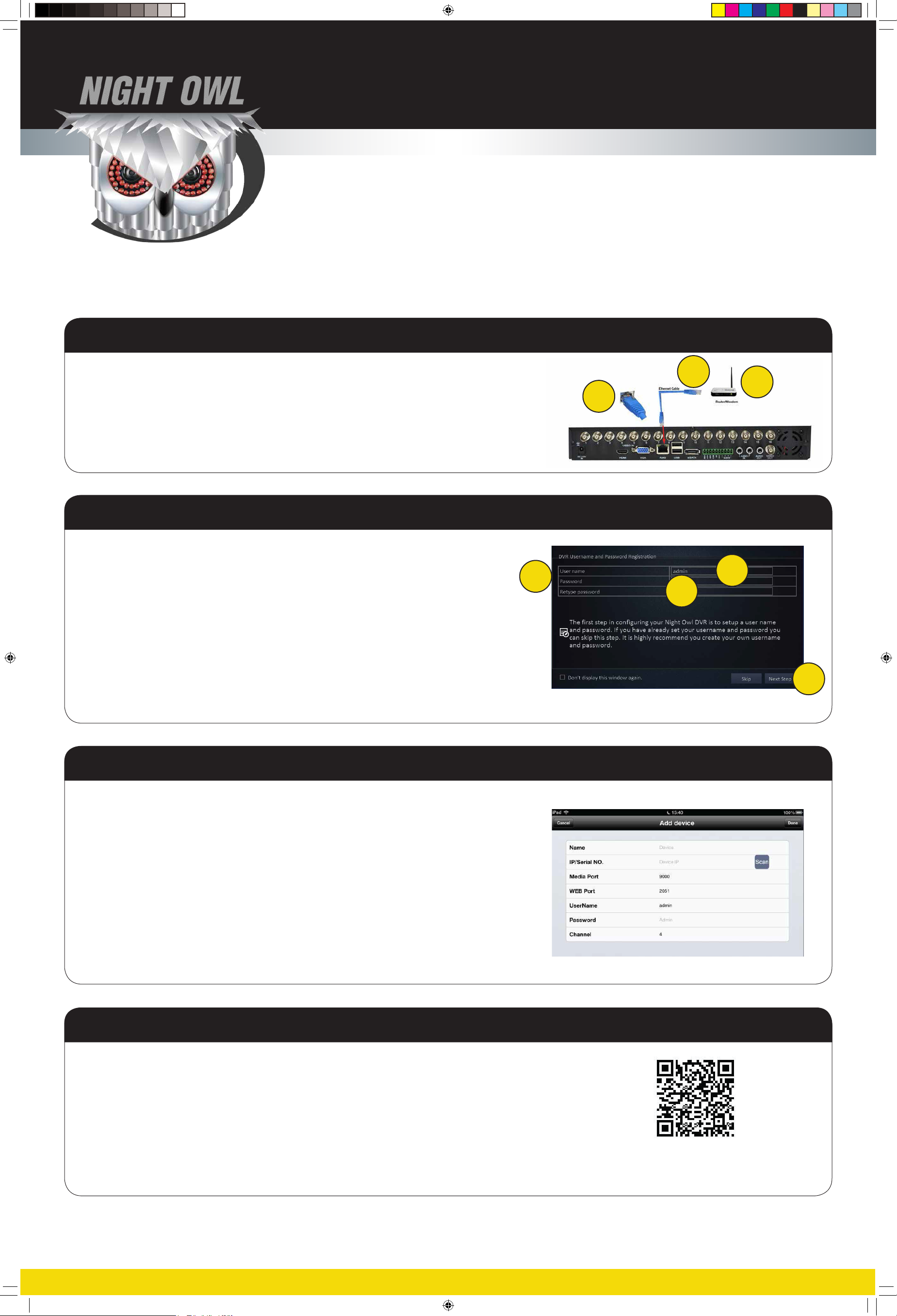
STEP 4: Connecting the DVR to a router or modem
A. Locate the blue Ethernet (RJ45) cable.
B. Connect one end of the Ethernet cable to the DVR’s LAN (RJ45) port.
C. Connect the other end of the Ethernet cable to an open port on the router/modem.
To confi gure remote viewing, please refer to the Remote Viewing chapter of the DVR manual.
STEP 5: Entering a User name and Password
A When you first power up your DVR you will be prompted for a User name
and Password.
B. Click in the User name text field to bring up the onscreen keyboard.
Enter a User name and then click outside of the keyboard to save.
C. Enter a Password in the appropriate field. Confirm your password by typing
it again in the Retype password field.
A
B
C
A
B
C
D. Click Next Step to proceed.
Be sure to write down all user names and passwords and keep them in a secure place.
STEP 6: Automatic network and system setup
1. On the next screen, click Automatic to begin setup. If you are a returning user or
want to customize your settings click Manual and follow the onscreen instructions.
2. Verify that you are connected to the internet by clicking Test. Once you are connected,
click Next Step.
3. Next you will be prompted to set up mobile access. If you do not need the feature
click Live Feed; otherwise, click Next Step to begin set up and follow the onscreen
instructions.
4. Download the Night Owl Pro app to your mobile device then click Next Step on your
TV/monitor.
D
5. In the Night Owl Pro app, click the + button. Proceed to Next Step onscreen to begin
mobile access with Owl Scan™.
STEP 7: Using Owl Scan™ for mobile access
1. Scan the QR code onscreen with your mobile device.
2. A confirmation screen will appear that will match your app screen. Click Next Step to choose your device.
3. Select the device from the listing on the app. Click Next Step and you are done!
Refer to your User Manual on the CD to learn how to confi gure
all of the features of your Night Owl Security Kit.
Please visit our website at www.NightOwlSP.com for all manuals, software, and fi rmware updates.
There are also free How-To videos with step-by-step instructions for confi guring the settings on your DVR.
This QR code is for reference ONLY. Your security system
will generate a unique QR code onscreen for you to scan
with the Night Owl Pro app. Do NOT scan this printed QR code.
QSG Pro Series_English.indd 2 1/10/14 4:38 PM
 Loading...