

Night Owl LTE-168500 User Manual
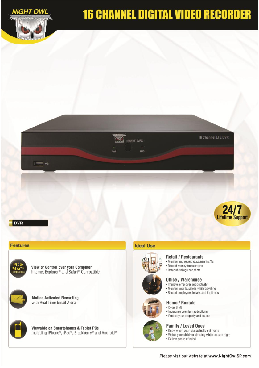


Table of Contents
Chapter 1 FCC Radiation Norm .............................................................. 5
Chapter 2 Package Contents .................................................................. 6
Chapter 3 System Requirements ............................................................ 7
Chapter 4 Safety Instructions .................................................................. 8
Chapter 5 Troubleshooting .................................................................... 10
Chapter 6 Layout of DVR Components ................................................. 12
6.1 Back Panel of DVR ................................................................. 12
6.2 Front Panel of DVR ................................................................. 13
6.3 Mouse ...................................................................................... 14
6.4 Remote .................................................................................... 15
Chapter 7 DVR Installation .................................................................... 16
7.1 Connecting the Power Supply ................................................. 16
7.2 Connecting the DVR to a TV or Monitor ................................. 17
Chapter 8 Camera Installation ............................................................... 18
8.1 Connecting Cameras to the DVR ........................................... 18
8.2 Mounting the Cameras ............................................................ 19
Chapter 9 DVR Start Up ........................................................................ 20
9.1 System Initialization ................................................................ 20
9.2 On-Screen Display .................................................................. 21
Chapter 10 Quick Function Menu.......................................................... 22
Chapter 11 Main Menu .......................................................................... 23
Chapter 12 System Menu ...................................................................... 24
12.1 Time Setting Menu ................................................................ 25
12.1.1 DST Setting Submenu ............................................... 26
12.2 Password Menu .................................................................... 27
12.2.1 User Password Setup Submenu ............................... 28
12.2.2 User Authority Submenu ........................................... 29
2

Table of Contents
12.3 Language Menu .................................................................... 30
12.4 HDD Management Menu ...................................................... 31
12.5 Video Audio Setup Menu ...................................................... 32
12.6 Maintain Menu ....................................................................... 33
12.6.1 Load Defaults Submenu ............................................ 34
12.6.2 Log Submenu ............................................................ 35
12.7 Firmware Update ................................................................... 36
12.8 System Information Menu ..................................................... 37
Chapter 13 Record Functions Menu ..................................................... 38
13.1 Record Menu ......................................................................... 39
13.1.1 Record Schedule Submenu ....................................... 40
13.2 Motion Detect Menu .............................................................. 41
13.2.1 Detection Area ........................................................... 42
13.3 Alarm Setup Menu ................................................................ 43
Chapter 14 Playback Menu ................................................................... 44
14.1 Playback Screen ................................................................... 45
14.2 Detail Files Submenu (Backup Files) .................................... 46
Chapter 15 Converting Files to AVI ....................................................... 47
Chapter 16 Camera Menu ..................................................................... 48
16.1 Camera Settings Menu ......................................................... 49
16.1.1 Privacy Zone Submenu ............................................. 50
16.1.2 Color Setup Submenu ............................................... 51
16.2 PTZ Menu .............................................................................. 52
16.3 PTZ Quick Functions............................................................. 53
Chapter 17 Network Menu .................................................................... 55
17.1 Internet/LAN Menu ................................................................ 56
17.1.1 DDNS Submenu ........................................................ 58
3

Interactive How-To videos are available for the
chapters indicated with this icon.
You can also visit Night Owl’s website at
http://www.nightowlsp.com/Videos
Table of Contents
17.2 Mobile Menu .......................................................................... 59
17.3 Email Menu ........................................................................... 60
Chapter 18 Remote Access .................................................................. 61
18.1 Connection of DVR and Router/Modem ............................... 62
18.2 Windows Network Configuration ........................................... 63
18.3 Apple (Mac) Network Configuration ...................................... 66
Chapter 19 Port Forwarding .................................................................. 68
19.1 Checking the Ports after Port Forwarding............................. 70
Chapter 20 DDNS Registration ............................................................. 71
20.1 Registering a Free Domain Name ........................................ 71
20.2 Adding your New Domain Name to your DVR ...................... 73
Chapter 21 NetViewer Software ............................................................ 74
Chapter 22 Control Management Software (CMS) ............................... 84
Chapter 23 Mobile Application ............................................................ 106
Chapter 24 Specifications of DVR ....................................................... 118
Chapter 25 Information Log ................................................................. 119
Chapter 26 Warranty ........................................................................... 120
4

Chapter 1 FCC Radiation Norm
FCC
This equipment has been tested and found to comply with limits for Class B
digital device pursuant to Part 15 of Federal Communications Commission
(FCC) rules.
FCC Compliance Statement
These limits are designed to provide reasonable protection against
frequency interference in residential installation. This equipment generates,
uses, and can radiate radio frequency energy, and if not installed or used in
accordance with the instructions, may cause harmful interference to radio
communication. However, there is no guarantee that interference will not
occur in television reception, which can be determined by turning the
equipment off and on. The user is encouraged to try and correct the
interference by one or more of the following measures:
Reorient or relocate the receiving antenna
Increase the separation between the equipment and the receiver
Connect the equipment into an outlet on a circuit different from that to
which the receiver is connected to.
CAUTION!
The Federal Communications Commission warns the user that changes or
modifications to the unit not expressly approved by the party responsible for
compliance could void the user’s authority to operate the equipment.
5
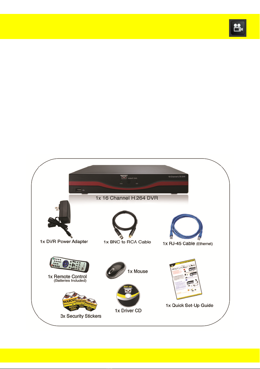
Chapter 2 Package Contents
Your new DVR Security Kit will contain the following items.
16 Channel DVR
Power Adapter 12V 2A
Remote Control
USB Mouse
BNC to RCA Cable
Ethernet (RJ45) Cable
Quick Setup Guide
Software CD
6

Chapter 3 System Requirements
Please be sure the computer that you will use the LTE DVR Security Kit with
complies with the following specifications:
IBM PCs or 100% Compatible
Windows® XP, Vista, 7, and 8
Mac® OS 10.6 and above
Internet Explorer 7, 8, 9 and 10 web brower
Mac capabilities Safari 5.1 & 6.0
CD-ROM Drive
7

Chapter 4 Safety Instructions
Use provided power adapter.
Do not use this product with a power source that applies more than
specified voltage (100-240V AC).
Never insert metal into the DVR case or its openings.
Inserting metal into the DVR case may cause electric shock.
Do not operate in wet or dusty area.
Avoid placing the DVR in areas such as a damp basement or dusty
attic.
Do not expose the DVR to rain or use near water.
If the DVR accidentally gets wet, unplug it and contact technical
support immediately.
Keep product surfaces clean and dry.
To clean the outside case of the DVR, use a lightly dampened cloth.
Do not use any cleaning solutions or solvents.
Do not install near any heat sources.
Do not install the DVR near any heat sources such as Stoves, heat
registers, radiators, other apparatus (including amplifier) that produce
heat.
Unplug the DVR when moving the device.
Be sure that the DVR is unplugged before you try to move the device.
When moving this device, be sure to handle it with care.
Make sure there is good air circulation around the unit.
This DVR system uses an internal hard drive, which generates heat
during operation, for video storage. Do not block vents on the DVR
that reduce the generated heat while the system is running. Place this
product in a well-ventilated area.
8

Chapter 4 Safety Instructions
Do not attempt to remove the top cover.
If any abnormal operation is observed, unplug the DVR immediately
and contact technical support. Do not attempt to open the DVR to
diagnose the cause of the malfunction yourself. (Warning: You may
be subjected to severe electrical shock if you remove the cover of the
DVR.)
Handle the DVR carefully.
If you accidentally drop your DVR on any hard surface, it may cause a
malfunction. If the DVR doesn’t work properly due to physical damage,
contact an authorized dealer for repair.
Recommended to use with an uninterruptable power supply (UPS).
Connecting your DVR and cameras to a UPS allows continuous
operation even during power outages. The run-time duration will
depend on the rating of the UPS used.
9
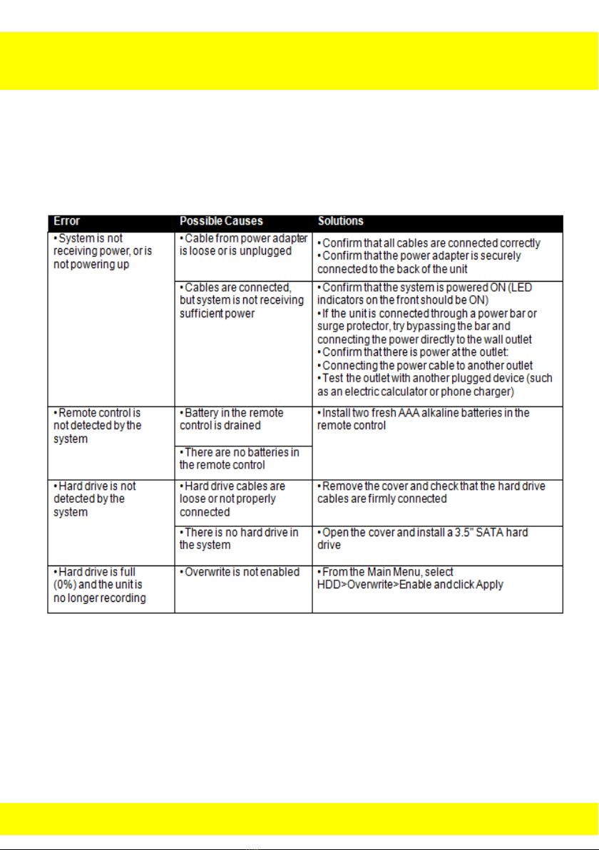
Chapter 5 Troubleshooting
When a malfunction occurs, it may not be serious and can be corrected
easily. The following information describes the most common problems with
their solutions. Please refer to the following before calling Night Owl
Technical Support.
10
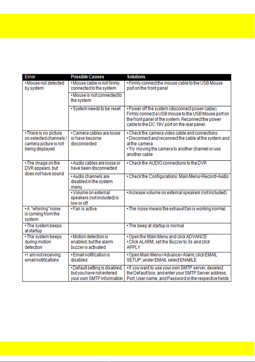
Chapter 5 Troubleshooting
11
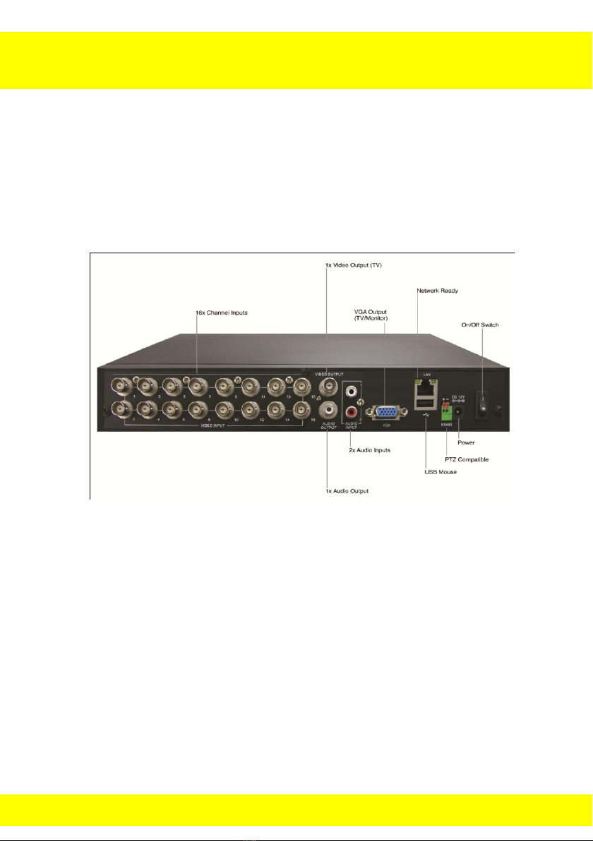
Chapter 6 Layout of DVR Components
6.1 Back Panel of DVR
12
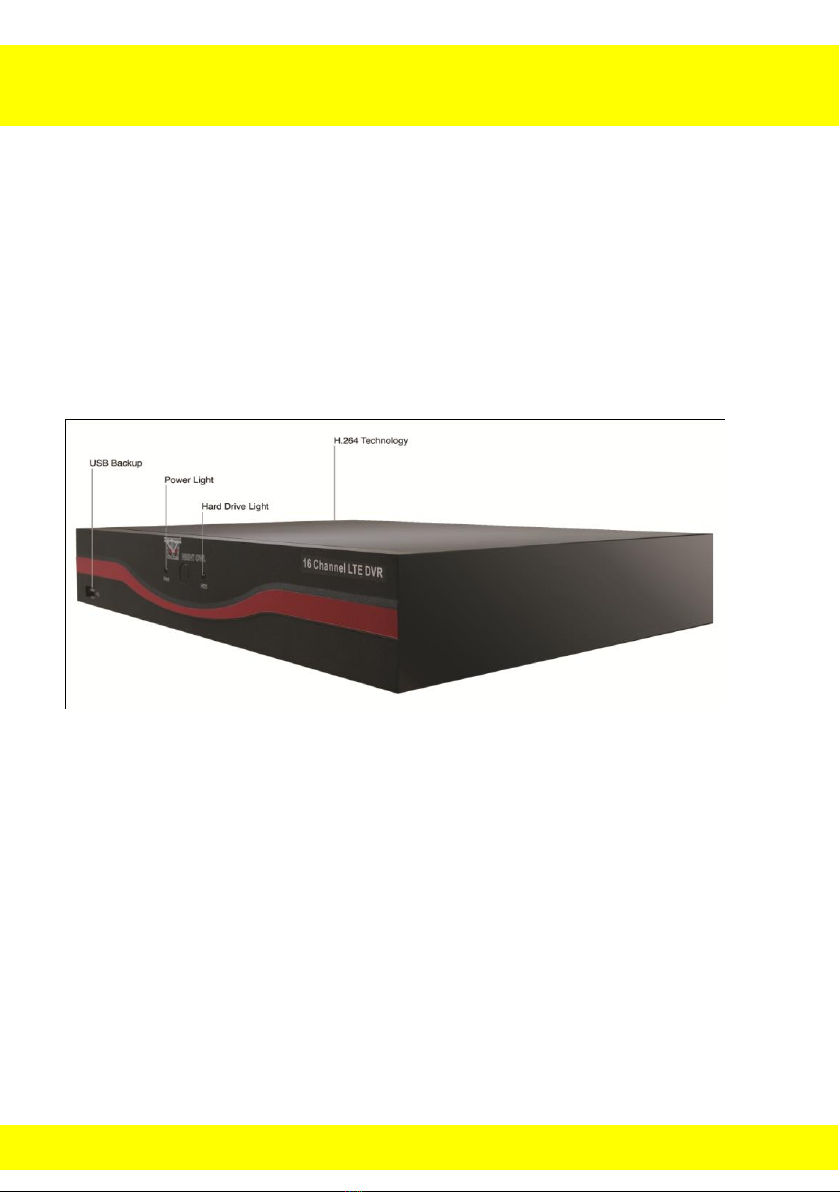
Chapter 6 Layout of DVR Components
6.2 Front Panel of DVR
13
Chapter 6 Layout of DVR Components
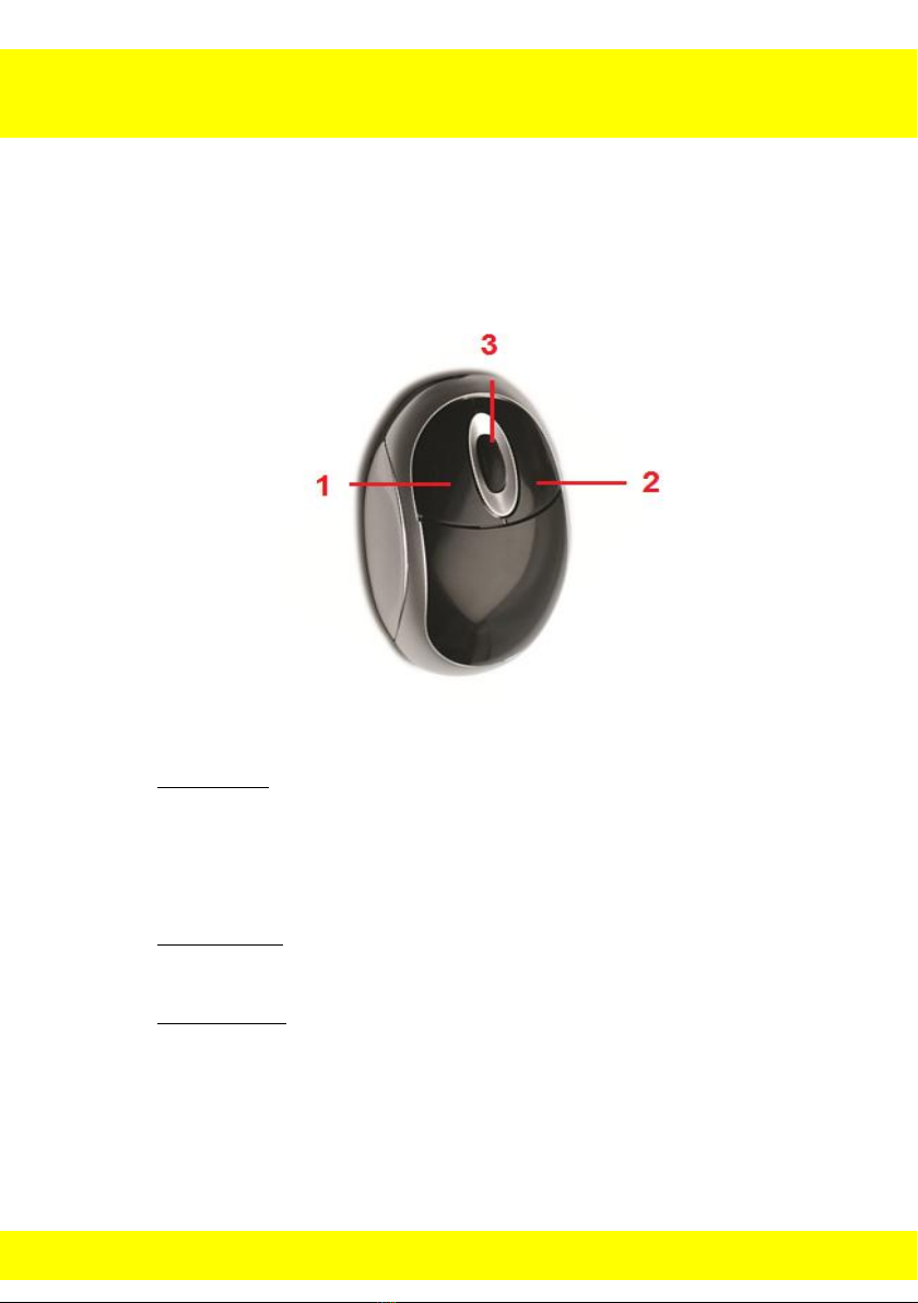
6.3 Mouse
You can use a mouse instead of the remote control to navigate through
your DVR’s menus. Connect the included mouse to the USB port on the
back panel of the DVR.
Use the mouse buttons to perform the following:
1. Left Button: Click to select a menu option. During live viewing in
split-screen, double-click on a channel to view the selected channel
in full-screen; double-click the channel again to return to split-screen
view.
2. Right Button: Click to open the quick function menu, or click to return
to previous option menu.
3. Scroll Wheel: No function.
14

REC
Start Recording Manually
SEARCH
Turns Search Menu
2x2
Change Display into 2x2 mode
3x3
Change Display into 3x3 mode
4x4
Change Display into 4x4 mode
AUTO
Put display in preset display sequence
0-9
Channel Select
DISPLAY
MODE
Press to rotate between different display
modes
▲▼◄►
Press to navigate in option menus
Enter
Press to go into sub menu
MENU/ESC
Enter / Exit Menu
FWD
Forward
REW
Rewind
PLAY
Play
STOP
Stop
PAUSE/FRAME
Press to pause or play frame by frame
SLOW
Play in Slow motion
Z+ Z-
Zoom in and out when in PTZ control
F+ F-
Adjust Focus when in PTZ control
I+ I-
Change the focus point in PTZ control
PTZ
Open PTZ control
LOCK
Put DVR in lock mode
Chapter 6 Layout of DVR Components
6.4 Remote Control
Use the remote control to navigate through the DVR’s menus.
15
Chapter 7 DVR Installation
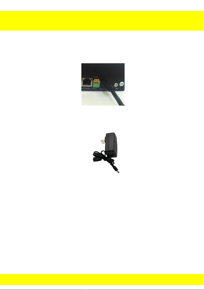
7.1 Connecting the Power Supply
1. Plug the included power supply into the DVR.
2. Plug the other end of the power adapter cable into an available
110/220V wall outlet (or, if you are using an uninterruptable power
supply, plug the adapter cable into one of its output sockets).
16
Chapter 7 DVR Installation
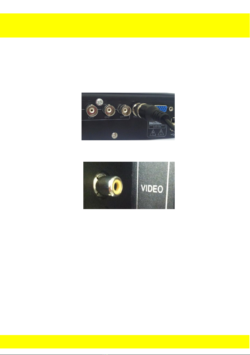
7.2 Connecting the DVR to a TV or Monitor
Using the supplied BNC to RCA connector
1. Connect the BNC to RCA connector to the back of the DVR’s Video
Output port.
2. Connect the other end of the cable to an available RCA video input
on your TV or monitor.
3. Select the appropriate video input channel on your TV or monitor to
view the DVR.
17
Ensure all cameras are working (prior to mounting the cameras)
by connecting them as described in the section above. Once all
cameras are confirmed to be fully operational, you can run the
cables and mount the cameras at their final locations.
Chapter 8 Camera Installation
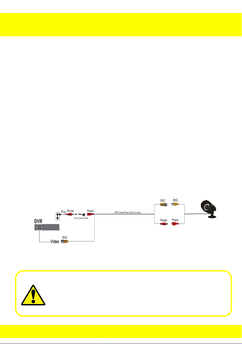
8.1 Connecting Cameras to the DVR
1. Your DVR system comes with one 60 foot coaxial cable per camera.
Connect each cable to a camera using the BNC connectors (yellow
connector) and the DC connectors (red connector).
2. Plug the other end of the cables into the video input ports on the
back panel of the DVR.
3. Connect the provided four-way power splitter cable into the DC
connectors of the cables.
4. Plug the power splitter into the camera power supply.
5. Plug the camera power supply into an available 110/220V wall outlet
or uninterruptable power supply.
18

Chapter 8 Camera Installation
Don’t feel like installing the system yourself?
Let InstallerNet do the work for you.
Contact us at 1-800-806-5513 or visit us at
www.nightowlsp.com/
8.2 Mounting the Cameras
1. Choose a Position: Decide where you would like to mount the
camera.
2. Screw Positions: Mark three holes on the surface where you plan to
mount the camera, using the holes in the camera base as a guide.
3. Anchor Screws: Using a drill bit slightly smaller than the included
screw anchors, drill into the mounting surface using the guide
marks placed in the previous step. Insert the screw anchors.
4. Mount Camera: Hold camera in place and tighten each screw
securely into the anchors.
5. Ensure Camera is Secure: Once screwed into place, make sure
that the camera is securely mounted by placing gentle pressure on
the mount.
6. Adjust: Adjust the camera housing to point the camera lens in the
direction you would like to record.
19
Chapter 9 DVR Start Up
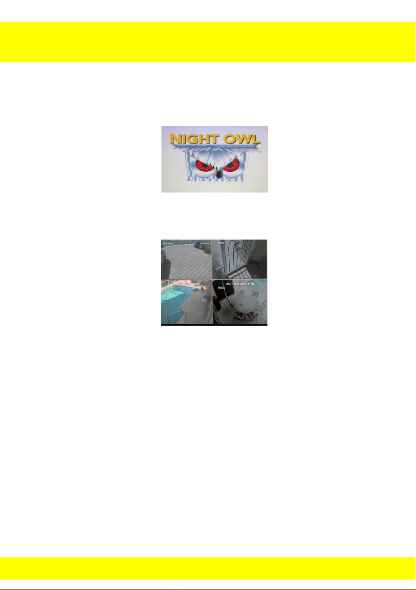
9.1 System Initialization
After connecting the power adapter, the system will automatically start up
and display the Night Owl logo while initializing the system for use.
After initialization, the view of your screen will change to a live camera view,
showing all the cameras that are currently connected to the DVR.
When there are video inputs, the main interface will display live images
from the cameras. Using the mouse:
Double-click (with the left button on the mouse) the live image of
any channel to maximize the image to a full screen.
Double-clicking again to go back to the live split screen, displaying
images from all channels.
Clicking the right button of the mouse will launch the quick function
menu; in this menu, you can use the left button to select menu
options. Clicking outside of the menu box will close the quick
function menu.
When you are inside a menu option, always right click to navigate
back to your live screen view.
20

Chapter 9 DVR Start Up
By default, passwords are disabled on the system. However, for
security purposes, it is highly recommended that you enable a
system password (this is discussed in detail later).
9.2 On-Screen Display
The on-screen display will also show the following information.
Date & Time: Displays the date and time on the system.
Channel Title/Number: Displays the channel name, configurable in
the Camera Menu.
Record Status: Displays the current recording status of the system:
R=Recording
M=Motion Recording
H= Hard Drive issue
21
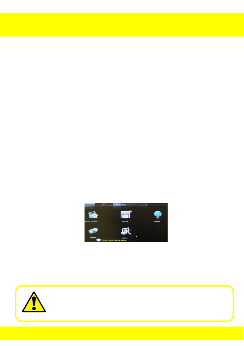
Chapter 10 Quick Function Menu
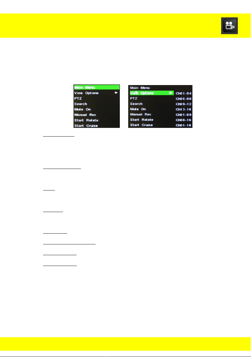
Use the Quick Function menu to access several system options, including
the Main Menu.
To open the quick function menu, right-click anywhere on the screen with
the mouse or press the Menu button on the remote control.
Main Menu: This opens the main system menu. This allows you to
access the System Menu, Record Functions Menu, Playback Menu,
Camera Menu, and Network Menu.
View Options: This allows you to view an individual camera, four
cameras, 9 cameras or all 16 cameras at once.
PTZ: Opens the Pan, Tilt, Zoom (PTZ) control menu. This option is
only for those who have a PTZ Camera.
Search: This opens the Playback Menu to search for previously
recorded videos.
Mute On: This will mute all audio enabled cameras.
(Stop) Manual Rec: This stops/starts continuous recording.
Start Rotate: This begins sequential channel rotation (a slideshow).
Start Cruise: This setting will automatically begin rotating the PTZ
camera to the preset points. This is only for those who have a PTZ
Camera.
22
Chapter 11 Main Menu
By default, passwords are disabled on the system. However, for
security purposes, it is highly recommended that you enable a
system password (this is discussed in detail later).
Use the Main Menu to access the System Menu, Record Functions Menu,
Playback Menu, Camera Menu, and Network Menu. These menus will
allow you to change the configurations of the DVR.
To access the Main Menu using a mouse:
1. Right click anywhere on the screen to open the quick function menu.
2. Left click the Main Menu option.
3. Left click the menu icon in which you would like to configure.
To access the Main Menu using the remote control:
1. Press the Menu button to open the quick function menu.
2. Use the arrow buttons to highlight the Main Menu option.
3. Use the enter button to select the option and enter the Main Menu.
4. Use the arrows to highlight the menu icon in which you would like to
configure.
5. Use the enter button to select the menu icon.
23
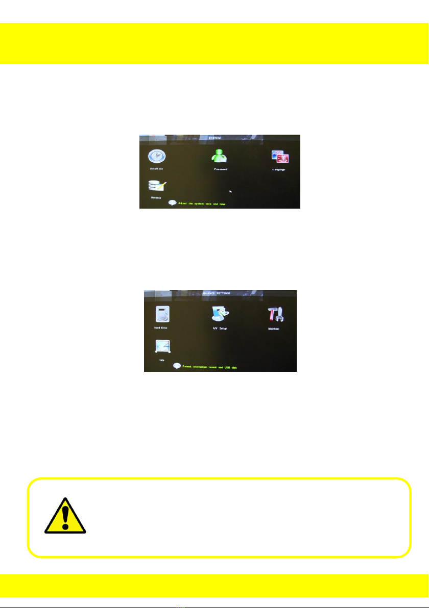
Chapter 12 System Menu
Be sure to “Apply” all changes made to the menus. If you do not
apply the changes, they will not be saved. You can also select the
“Default” button on any page to restore back to DVR default
settings.
System Menu
Use this menu to access the Date/Time, Password, Language and
Advance menus.
Use the Advance menu to access the Hard Drive, A/V Setup, Maintain and
Info Menus.
24
Chapter 12 System Menu
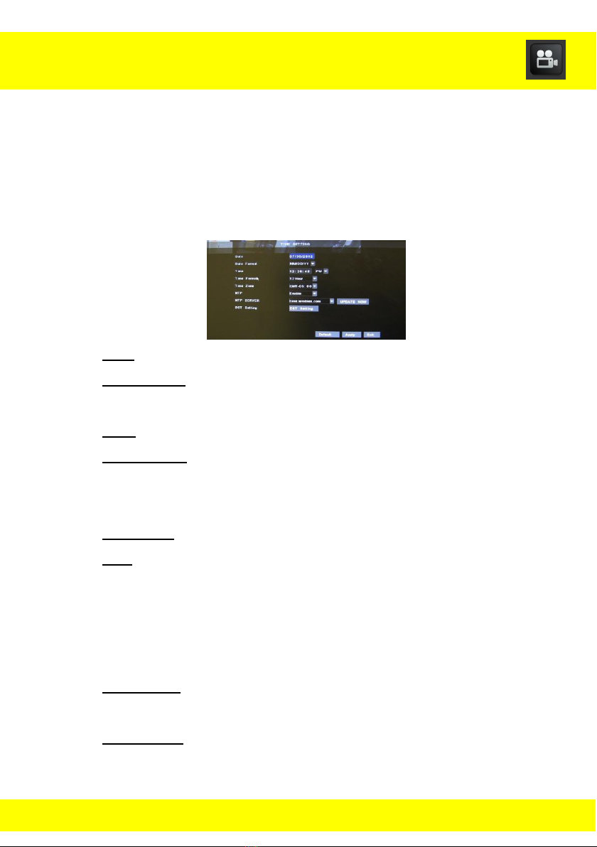
12.1 Time Setting Menu
It is highly recommended to set up the Date and Time when first setting up
your system. You can also configure Daylight Saving Time (DST) settings.
To access the Time Setting menu select System from the Main Menu, and
then select Date/Time from the System menu.
Date: Enter the current date.
Date Format: Select the format you would like the date to be
displayed in MM/DD/YY, YY-MM-DD, or DD/MM/YY.
Time: Enter the current time.
Time Format: Select 12 or 24 hour time format. 24 Hour displays as
military time, keep in mind most of the DVR’s functions are set as
military time.
Time Zone: Select your time zone.
NTP: This stands for Network Time Protocol. NTP is used to
retrieve and update your DVR’s time. It is only recommended to
enable this setting if you are connected to the internet. If you are
connected to the internet the DVR can automatically update the
time and will automatically update for Day Light Saving Time.
NTP Server: Enter the address of an international time server for
the DVR to update its time from.
DST Setting: Select the DST Setting button to enter the DST
Setting Submenu.
25
Chapter 12 System Menu
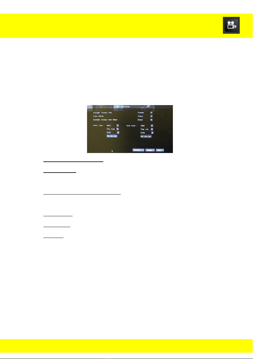
12.1.1 DST Setting Submenu
The DST Setting Submenu is used to configure Daylight Saving Time
settings.
To access the DST Setting Submenu select System from the Main Menu,
and then select Date/Time from the System menu. Select the DST Setting
button in the Date and Time Menu.
Daylight Saving Time: Enable/disable the DVR’s ability to use DST.
Time Offset: Select the number of hours that your time is offset by
DST.
Daylight Saving Time Mode: Select either Week or Date depending
on when DST takes effect.
Start Time: When the DVR should begin applying the DST offset.
End Time: When the DVR should stop applying the DST offset.
Default: Go back to original settings that came installed with the
DVR.
26
Be sure to write down the Admin Password in
the Information Log at the end of the manual
so that you do not get locked out of your DVR.
Chapter 12 System Menu
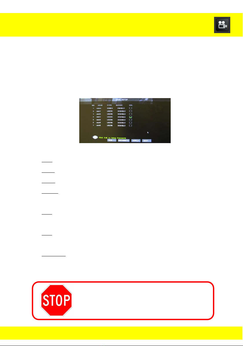
12.2 Password Menu
Use this menu to change the user name, passwords, and permissions of
the admin and the users from the User Setup menu.
To access the User Setup menu select System from the Main Menu, and
then select Password from the System menu.
NO.: This is the number of users that can be enabled.
User: This will indicate the User’s name when configured.
Type: This is the type of each user.
Active: This will indicate if each user name and password is
enabled/disabled.
Sel.: This will allow you check the box next to the user that you
want to edit.
Edit: This will open a submenu that will allow you change the name
and password of a user and enable the users and passwords.
Authority: This will open a submenu that will allow the Admin to
grant the users access to specific menus of the DVR.
27
Chapter 12 System Menu
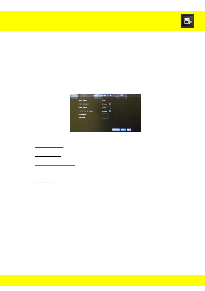
12.2.1 User Password Setup Submenu
Use this submenu to change the user names and passwords and to enable
user names and passwords.
To access the User Password Setup Submenu select System from the
Main Menu, and then select Password from the System menu. Place a
check mark into the box for the user you would like to edit and then select
the Edit button.
User Name: This will indicate what the current user type.
User Enable: This will enable/disable the user.
User Name: This will be where you can change the user name.
Password Enable: This will enable/disable a password for the user.
Password: This will be the password assigned to the user name.
Confirm: This will confirm the password that was assigned in the
Password field.
28
Chapter 12 System Menu
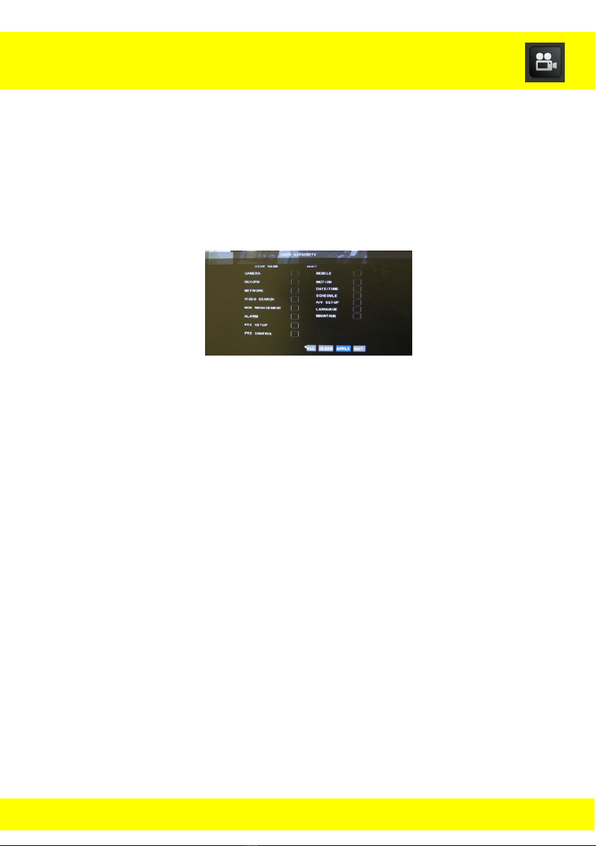
12.2.2 User Authority Submenu
Use this submenu to grant the users access to specific menus of the DVR.
To access the User Authority Submenu select System from the Main Menu,
and then select Password from the System menu. Place a check mark into
the box for the user you would like to grant access to and then select the
Authority button.
Place a check in each box for each menu you would like to grant
access into.
All: This will select all boxes for each menu.
Clear: This will deselect all checked boxes that are currently
checked.
29
 Loading...