

Night owl HDA30 User Manual
QUICK SETUP GUIDE
HDA30 SERIES
www.NightOwlSP.com
What’s in the Box
Package Contents
Disclaimer: The exact components of your system, images and
quantities may vary depending on your model number. While
these may vary, this QSG will address the setup and initial
configuration of your DVR and cameras.
DVR
Camera(s)
Dome Camera(s)
(If applicable)
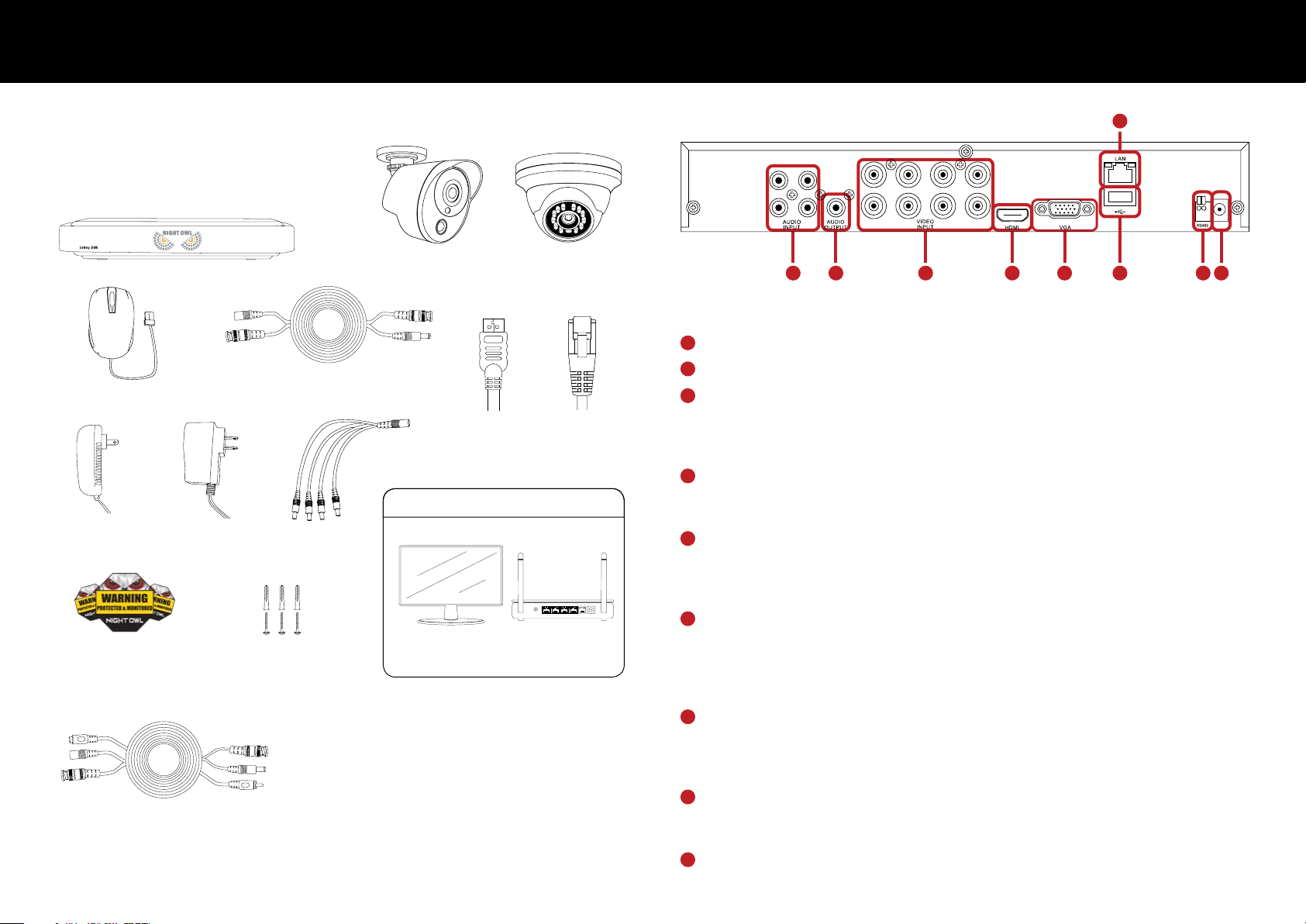
DVR Specifications
C
AB
D E G H I
F
Rear View
Images used are for reference only. Your product may vary slightly. An 8 channel model is displayed above.
A
Video Inputs – video inputs allow for the connection of BNC cameras.
B
60 ft. Video/Power Cables
USB Mouse (x1)
(1 cable per camera)
6 ft. HDMI
(x1)
6 ft. Ethernet
(x1)
Items Not Included
DVR Power
Adapter (x1)
Camera Power
Adapter(s)
Power
Splitter(s)
RESET
LAN1 LAN2 LAN3 LAN4 WAN
Monitor Router
Safety
Stickers
Mounting
Hardware
Your system may include an audio enabled camera. Each
audio enabled camera comes equipped with an audio
enabled BNC Video/Power cable. Simply connect the white
audio end of the BNC cable to an open audio input port on
the rear of the DVR and ensure the audio input port number
and channel port number match. For instance, if you have
60 ft. Video/Power/Audio Cables
(If applicable:1 cable per camera)
an audio enabled cable plugged into video input port 1, it
will also need to be connected to audio input port 1. After
making the audio input connection, be sure to enable the
audio function in the DVR’s menu.
1 2
Audio Output – audio output allows for the connection of an amplified speaker.
C
Audio Inputs – audio inputs allow for the connection of audio enabled cameras
by connecting the white RCA plug to one of the audio inputs. After making
the audio input connection, be sure to enable the audio function in the DVR’s
menu interface.
D
HDMI Output – HDMI output allows for a video connection. If the TV/Monitor has
an HDMI input, connect the HDMI cable from the HDMI output port on the DVR
to the HDMI input port on your TV/Monitor.
E
VGA Output – VGA output allows for a video connection. If the TV/Monitor does
not have an HDMI input but does have a VGA input, connect the VGA cable from
the VGA output port on the DVR to the VGA input port on your TV/Monitor. (VGA
cable is not included)
F
RJ-45 (Ethernet) Port – RJ-45 port will be used to connect the DVR to your router/
modem via the included Ethernet cable. Keep in mind, you can quickly network
your DVR to begin viewing your cameras remotely right from your mobile device by
completing the DVR’s Startup Wizard once you have connected the DVR to your
router and powered on the DVR.
G
USB Ports – USB ports allow for the connection of a USB mouse and/or a USB
flash drive. You will connect the included USB mouse to assist you in navigating
the DVR’s menu interface. You will connect a USB flash drive to download video
files from the DVR and save them to your USB flash drive.
H
RS-485 (PTZ) Port – RS-485 port allows for the connection of a Pan-Tilt-Zoom
(PTZ) camera. Some PTZ cameras utilize Up the Cable (UTC) technology and will
not require the RS-485 port to function.
I
Power Input – power input to connect the included 12V DC power supply.
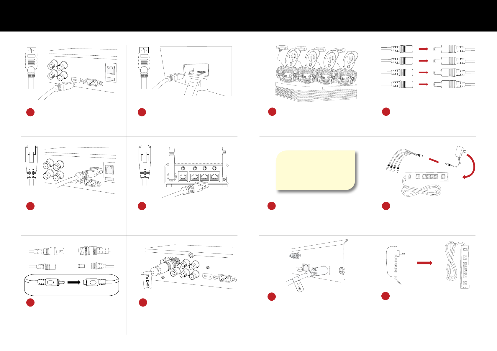
Connecting Your System
HDMI
Plug one end of the included
1
HDMI cable into the HDMI
port on the back of the DVR.
Plug one end of the included
3
Ethernet cable into the LAN
port on the back of the DVR.
TO CAMERAFROM CAMERA
Make sure you twist and lock BNC connectors
HDMI
You may also connect using VGA (not included)
Plug the other end of the HDMI
2
cable into the back of your
TV or monitor.
Router Not
Included
ETHERNETETHERNET
Plug the other end of the Ethernet
4
cable into a port on the back
of your router.
To ensure all cameras are
7
working, please test each one
locally before installing them.
The DVR power adapter is
labeled Power supply for DVR
The Camera power adapter is
labeled Power supply for Camera
Ensure you are using the
9
correct power adapter when
setting up your system.
Power cable
connectors
Connect the female power
8
Power splitter
connectors
leads of the BNC cables to the
male power splitter ends.
Camera Power
Adapter
Power
splitter
Connect the power splitter to the
10
Surge
Protector not
included
camera power adapter and plug
the adapter into a surge protector or
Uninterruptible Power Supply (UPS).
Surge
Protector not
included
Audio enabled cameras will have a white RCA
connector to transmit audio signal (Optional).
Connect the ends of the cable
5
attached to the camera to the
ends of a video/power cable
labeled TO CAMERA ONLY.
3 4
Connect the BNC connector of
6
the video/power cable labeled
TO DVR ONLY to an open video
input on the DVR.
Connect the DVR power adapter
11
to the Power Input on the rear of
the DVR.
Plug the DVR power adapter into a
12
surge protector or Uninterruptible
Power Supply (UPS).
 Loading...