

Night Owl 4BL-DVR-1TB User Manual
Rev. 110607

TABLE OF CONTENTS
FCC RADIATION NORM:.................................................................................................................................................2
PACKAGE CONTENTS:..................................................................................................................................................3
SYSTEM REQUIREMENTS:............................................................................................................................................3
SAFETY INSTRUCTION:.................................................................................................................................................4
CHAPTER 1: DVR FEATURES........................................................................................................................................5
CHAPTER 2: INSTALLING HARD DISK DRIVE.............................................................................................................6
CHAPTER 3: LAYOUT.....................................................................................................................................................8
3.1 FRONT PANEL (PLEASE REFER TO ACTUAL PRODUCT FOR DETAIL)..............................................................................8
3.2 REAR PANEL (PLEASE SEE ACTUAL PRODUCT FOR DETAIL) ........................................................................................9
3.3 REMOTE CONTROL..................................................................................................................................................10
3.4 MOUSE OPERATION ................................................................................................................................................11
CHAPTER 4: DVR/CAMERA INSTALLATION..............................................................................................................12
4.1 CONNECTING THE DVR TO A TV OR MONITOR..........................................................................................................12
4.2 CONNECTING THE POWER SUPPLY...........................................................................................................................12
4.3 CONNECTING THE CAMERAS....................................................................................................................................12
CHAPTER 5: DVR START UP.......................................................................................................................................13
5.1 SYSTEM INITIALIZATION ...........................................................................................................................................13
5.2 MAIN INTERFACE.....................................................................................................................................................13
CHAPTER 6: DVR MENU AND OPTIONS ....................................................................................................................14
6.1 MAIN MENU PREVIEW..............................................................................................................................................15
6.2 MAIN MENU ............................................................................................................................................................16
6.2.1 Recording Functions ..................................................................................................................................16
6.2.1.1 Record Setup......................................................................................................................................................... 16
6.2.1.2 Motion ....................................................................................................................................................................17
6.2.1.3 Alarm......................................................................................................................................................................17
6.2.2 Playback.......................................................................................................................................................18
6.2.3 Network Setup – Intranet (Internal Access)..............................................................................................20
6.2.4 Network Setup – Global Access (Connected Directly to Modem)..........................................................21
6.2.5 Network Setup – Global Access (Connected through a Router or Firewall).........................................23
6.2.6 Port Forwarding...........................................................................................................................................24
6.2.7 Viewing your NightOwl DVR over the Internet (UPNP)............................................................................25
6.2.8 Accessing the DVR through Internet Explorer Browser (IE):.................................................................26
6.2.9 Mobile Setup................................................................................................................................................28
6.2.10 Mobile Phone and Tablet PC Access ......................................................................................................28
6.2.11 E-Mail Setup...............................................................................................................................................38
6.2.12 Camera .......................................................................................................................................................39
6.2.12.1 Camera Setup...................................................................................................................................................... 39

User’s Manual
6.2.12.2 PTZ .......................................................................................................................................................................39
6.2.13 System........................................................................................................................................................40
6.2.13.1 Date/Time.............................................................................................................................................................40
6.2.13.2 Password............................................................................................................................................................. 40
6.2.13.3 Language............................................................................................................................................................. 41
6.2.13.4 Hard Drive............................................................................................................................................................41
6.2.13.5 Video .................................................................................................................................................................... 41
6.2.13.6 System Maintenance........................................................................................................................................... 42
6.2.13.7 Info........................................................................................................................................................................42
6.3 LOCK......................................................................................................................................................................42
6.4 PTZ CONTROL........................................................................................................................................................43
6.4.1 Cruise Setup ................................................................................................................................................43
6.5 PIP MODE........................................................................................................................... ..................................43
6.6 SEARCH............................................................................................................................... ...................................43
6.7 MUTE .....................................................................................................................................................................43
6.8 MANUAL REC..........................................................................................................................................................43
6.9 START ROTATE.......................................................................................................................................................43
6.10 START CRUISE......................................................................................................................................................43
CHAPTER 7: NET-VIEWER PROGRAM.......................................................................................................................44
7.1 LOG-IN TO NET-VIEWER ..........................................................................................................................................44
7.2 MAIN INTERFACE OF NET-VIEWER............................................................................................................................45
7.2.1 Menu column ...............................................................................................................................................45
7.2.1.1 Live.........................................................................................................................................................................45
7.2.1.2 Playback.................................................................................................................................................................45
7.2.1.3. Remote Setting..................................................................................................................................................... 46
7.2.1.4. Local Setting......................................................................................................................................................... 46
7.2.1.5 Log out................................................................................................................................................................... 46
7.2.2 Play Control .................................................................................................................................................47
7.2.3 PTZ Control..................................................................................................................................................47
7.2.4 Remote Backup ...........................................................................................................................................47
7.2.5 Multi Player File format...............................................................................................................................48
1

User’s Manual
FCC RADIATION NORM:
FCC
This equipment has been tested and found to comply with limits for Class B digital device pursuant
to Part 15 of Federal Communications Commission (FCC) rules.
FCC Compliance Statement
These limits are designed to provide reasonable protection against frequency interference in
residential installation. This equipment generates, uses, and can radiate radio frequency energy,
and if not installed or used in accordance with the instructions, may cause harmful interference to
radio communication. However, there is no guarantee that interference will not occur in television
reception, which can be determined by turning the equipment off and on. The user is encouraged to
try and correct the interference by one or more of the following measures:
Reorient or relocate the receiving antenna
Increase the separation between the equipment and the receiver
Connect the equipment into an outlet on a circuit different from that to which the receiver is
connected to.
CAUTION!
The Federal Communications Commission warns the user that changes or modifications to the unit
not expressly approved by the party responsible for compliance could void the user’s authority to
operate the equipment.
2
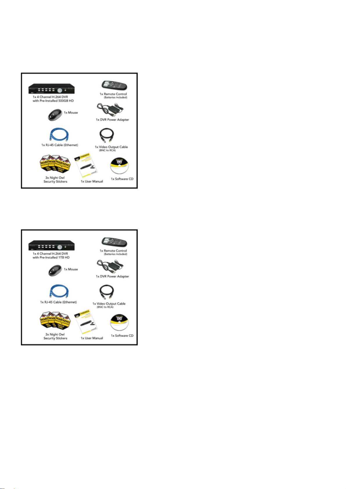
PACKAGE CONTENTS:
Your new Security Camera and DVR Kit will ship with the following items.
4BL-DVR5GB
User’s Manual
4BL-DVR1TB
SYSTEM REQUIREMENTS:
Please be sure the computer that you install the included software with complies with the following
specifications:
- IBM PCs or 100% Compatibles
- Windows® XP, Vista, 7
- Internet Explorer 7 or Newer Web Browser Software
- CD-ROM Drive (for software installation)
3

SAFETY INSTRUCTION:
1. Use proper power source.
Do not use this product with a power source that applies more than specified voltage
(100-240V AC).
2. Never insert any metal into the DVR or any openings.
Putting metal into the DVR case can cause danger of electric shock.
3. Do not operate in wet or dusty area.
Avoid places like a damp basement or dusty hallway.
4. Do not expose this product to rain or use near water.
If this product accidentally gets wet, unplug it and contact technical support immediately.
5. Keep product surfaces clean and dry.
To clean the outside case of the DVR, use a lightly dampened cloth (no solvents). Do not
use any cleaning solutions or cleaner.
User’s Manual
6. Provide proper ventilation.
Use in well ventilated area to avoid overheating of the device.
7. Do not attempt to remove the top cover.
If any abnormal operation is observed, unplug it immediately and contact technical support.
Warning: You may be subjected to severe electrical shock if you remove the cover of the
DVR.
8. Handle DVR box carefully.
If you accidentally drop your DVR on any hard surface, it may cause a malfunction. If the
DVR doesn’t work properly due to physical damage, contact an authorized dealer for repair
or exchange.
9. Recommended to use with UPS (Uninterruptable Power Supply)
Connecting your DVR and cameras to a UPS allows continue operation even during power
outages. The duration of power out usage time depends on types of UPS used.
10. Make sure there is good air circulation around the unit.
This DVR system uses a hard drive for video storage, which generates heat during
operation. Do not block air holes/vents (bottom, upper, sides and back) of the DVR that
reduce the generated heat while the system is running. Install or place this product in a well
ventilated area.
4

CHAPTER 1: DVR FEATURES
Other Features:
• H.264 compression
• Real time recording on 4 channels
• USB Backup to flash drive
• Triplex operation: view, record, playback simultaneously
• Easy control with USB mouse
• Instant viewing using Windows
Blackberry® OS 5, and Android®
• Internet Remote Functions*: View, Search & Playback, Backup and Setup
• Email alerts with JPEG attachment
• Microsoft Windows
®
XP, Vista, and 7 compatible
User’s Manual
®
Mobile™, Symbian® S60 Version 3 & 5, iPhone®,
5
User’s Manual
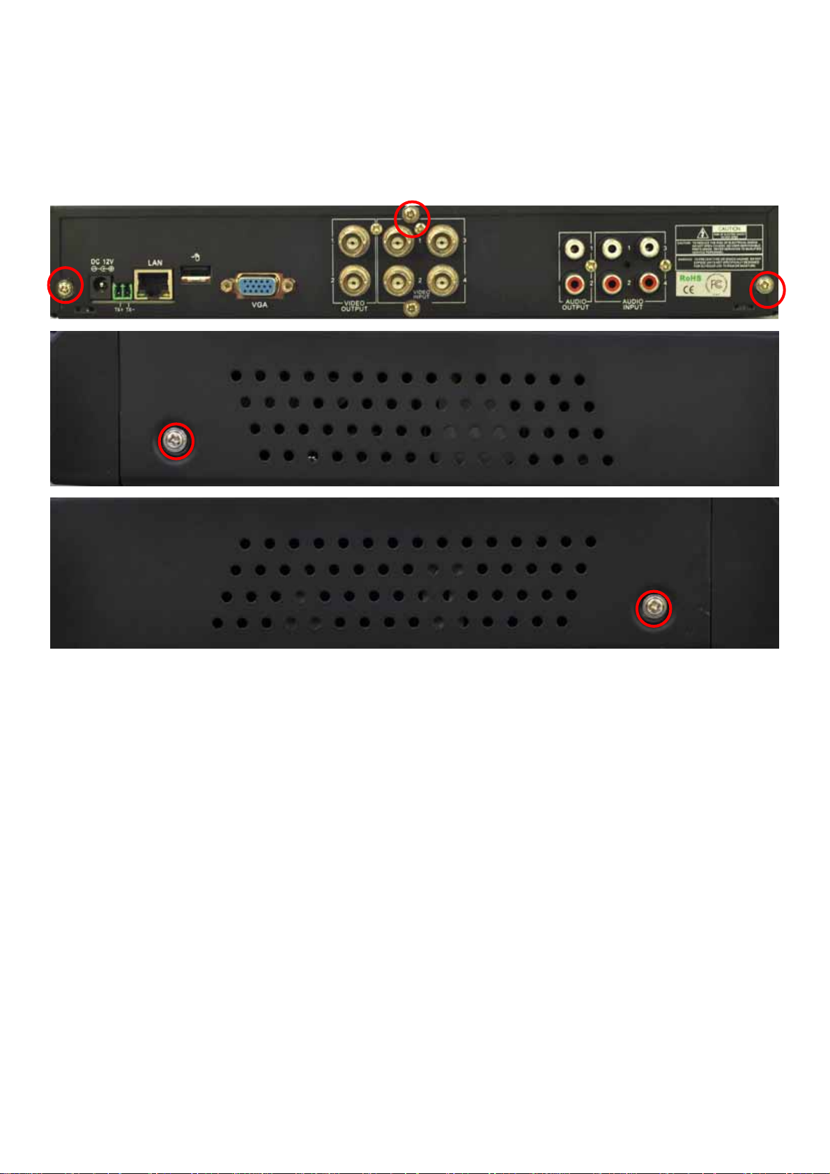
CHAPTER 2: INSTALLING HARD DISK DRIVE
If you have purchased a Digital Video Recorder (DVR) with pre-installed Hard Disk Drive (HDD),
please skip to Chapter 3. Opening DVRs with pre-installed HDD will void the warranty. To install
Hard Disk Drive to the DVR, please follow the instruction below:
1. Remove the 5 case screws located on the back and two sides of the DVR.
6
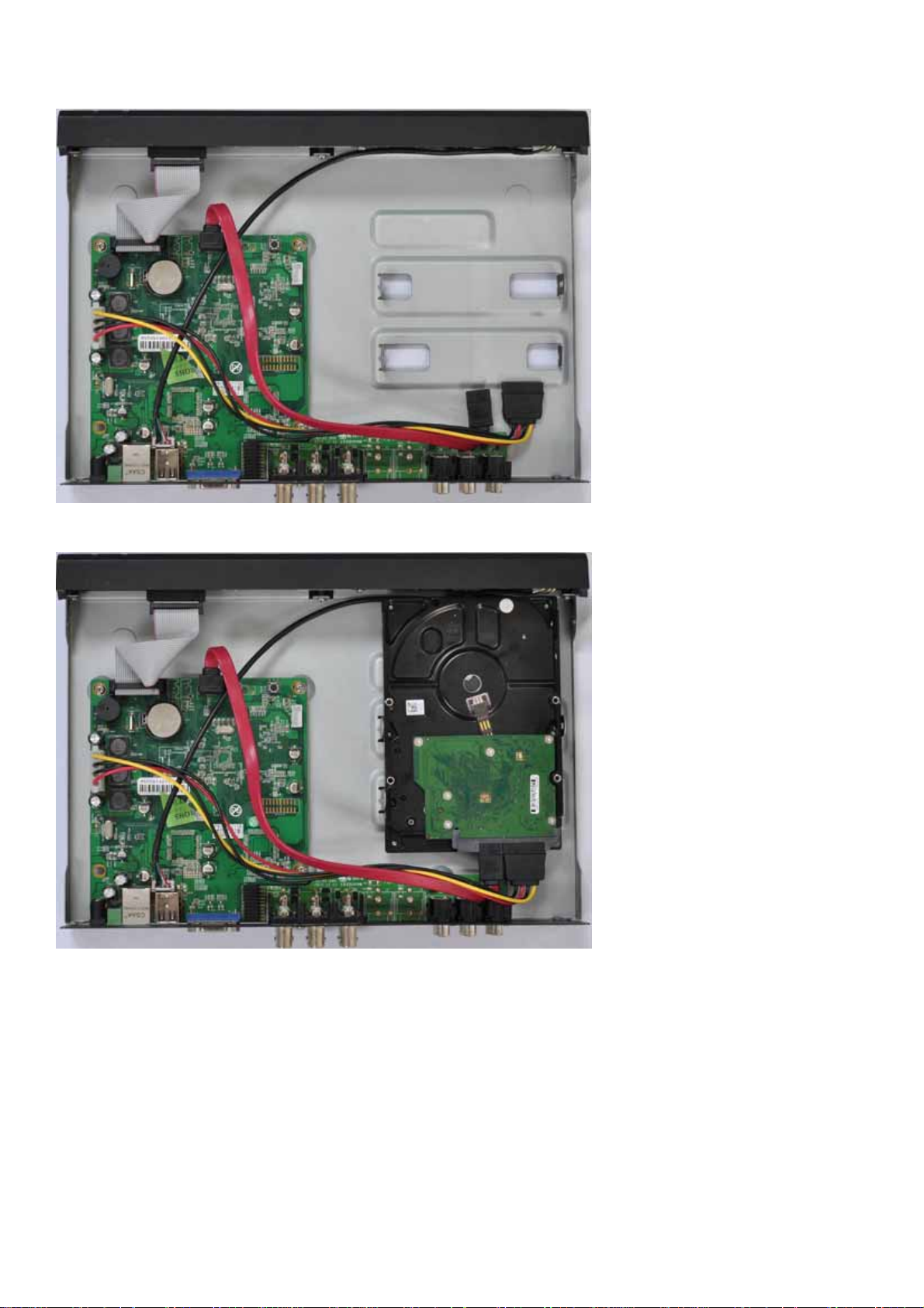
2. Locate the SATA Power and Data cable in your DVR.
User’s Manual
3. Connect the SATA Power and Data cable to the back of your Hard Disk Drive.
4. Mount the Hard Disk to your DVR using the included mounting screws.
5. Place the DVR cover back onto the DVR.
6. Use the 5 case screws removed from step 1 to mount the DVR Case to the DVR.
WARNING: The DVR case must be secured to the DVR using all 5 mounting screws. Operating
the DVR without the cover is extremely dangerous. It may cause severe injury and will void the
warranty.
7. Once your Hard Disk is installed successfully, please go to section 6.2.13.4 (HDD Management)
of this manual to format the Hard Disk. The Hard Disk must be formatted before it can be used.
7
CHAPTER 3: LAYOUT
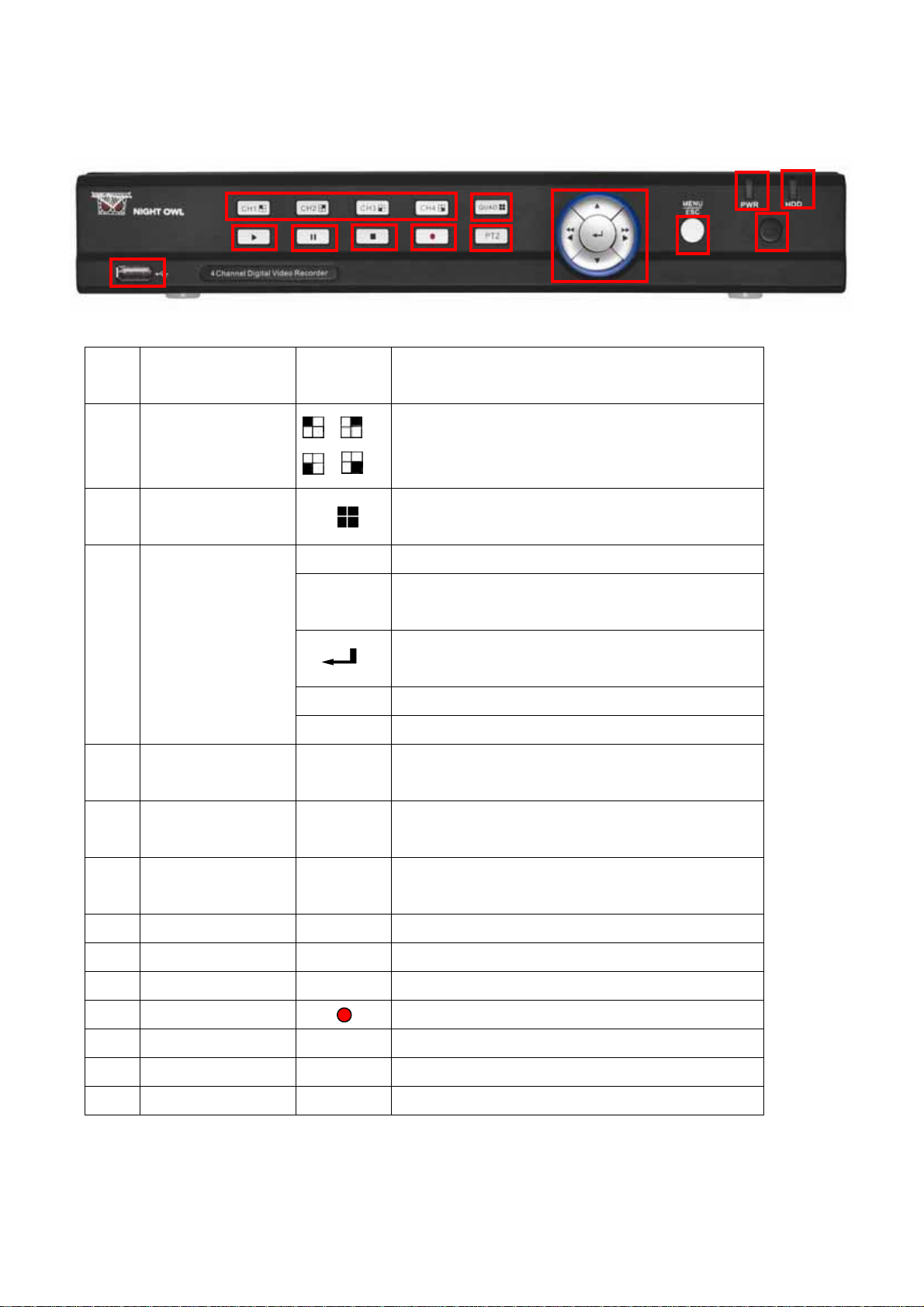
3.1 Front Panel (Please refer to actual product for detail)
User’s Manual
4
1
6
7
8
9
10
2
11
3
12
5
13
Buttons /
Item
Marks Functions
Indicators
1
Channel Select:
CH1 CH2 CH3
Select which single channel to display
CH4
Display all cameras in live display or
2
QUAD
playback mode
Move up
Move Left / Rewind / or hold for 5 seconds
to switch output between VGA and BNC
Navigation
3
Buttons
Select Button, press to enter pop up menu
Move Right / Play Forward
Move Down
If the “Green” indicator is on the system is
4
Power indicator
PWR
properly powered
When the “Red” indicator flashes it means
5
HDD indicator
HDD
the hard drive is being used.
Connect USB device (Flash Drive, Hard
6
USB Data Port
Drive)
7
8
9
10
11
12
13
PLAY
PAUSE
STOP
REC
PTZ
MENU/ESC
IR Receiver
PTZ
Play
Pause / play frame by frame
Stop Playback; stop manual recording
Start Manual recording
Move to PTZ (Pan Tilt Zoom) control mode
Enter into main menu or exit menu
Remote control signal receiver
8
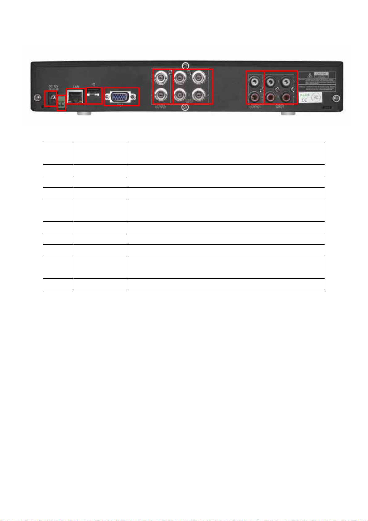
3.2 Rear Panel (Please see actual product for detail)
User’s Manual
1
2
3
4
6
5
7
8
9
Item
Physical
Connection method
ports
1 Power Port Connect power supply - DC12V 3A
2 PTZ Pan Tilt Zoom Output to PTZ enabled camera
3 Ethernet Port Connect intranet, internet (RJ45 interface)
4 USB Mouse
Connect Port to Mouse
Port
5 VGA Connect to monitors with VGA input port
6 Video outputs Connect to monitor inputs ( BNC interface)
7 Video inputs Connect CH1-4 ( BNC interface)
8 Audio Outputs Audio Signal Outputs to amplifier or audio equipments
(RCA interface)
9 Audio input 4 Channel (RCA interface for Channel 1~4)
9

3.3 Remote Control
The remote control is the secondary input device for navigating the system’s interface.
To use the remote control:
1-4 Channel Select 1-4
5-9 Digit Key 5-9
User’s Manual
0
Digit Key 0, or press to switch between VGA
and BNC output
ALL Display all Channels – Quad View
Menu Enter / Exit Menu
▲ UP
▼ Down
SEL Select
Rewind
Play
Forward
● Record
Pause / Play Frame by Frame
■ Stop
Audio No function for this particular model
Mute Enable or disable sound
10

3.4 Mouse Operation
You can use a mouse instead of the front panel buttons or remote control to navigate the
operation of your DVR
The mouse is the primary input device for navigating system menus.
To use a mouse with the system:
1. Connect a USB mouse to the USB MOUSE port on back panel of the system.
NOTE: Only the USB port on the front panel is designed for data backup to a USB flash
drive. Do not connect a USB flash drive to the USB MOUSE port on the rear panel.
2. Use the mouse buttons to perform the following:
a. Left-Button: Click to select a menu option; during live viewing in split-screen,
double-click on a channel to view the selected channel in full-screen; double-click
the channel again to return to split-screen view
User’s Manual
b. Right-Button: Click to open the Sub-Menu, or click to return to previous option
menu.
3. Scroll-Wheel: No function
11

User’s Manual
Chapter 4: DVR/Camera installation
4.1 Connecting the DVR to a TV or Monitor
Using the supplied BNC to RCA connector
1. Connect the BNC to RCA connector to the back of the DVR labeled Video Output (refer to
Chapter 3.2, Rear Panel Picture)
2. Connect the other end of the cable to an open RCA VIDEO input on your TV or Monitor
3. Select the appropriate video input on your TV or Monitor to view the DVR
NOTE: Your DVR must be powered on so you can view on your TV or Monitor.
4.2 Connecting the Power Supply
1. Plug the provided power supply into the back of the DVR labeled “DC12V”
2. Plug the other end of the power Adapter into any 110V outlet within your home or business.
NOTE: Connecting your DVR and Cameras power source into a UPS or battery backup system will
provide you recorded coverage after power failures. Time depends on type of UPS used.
NOTE: Ensure the cable is pushed all the way into the power supply. Otherwise the DVR will not
power on!!
4.3 Connecting the Cameras
NOTE: Prior to mounting the cameras to their desired destination, please ensure all cameras are
working. Perform these steps near the DVR. Once all cameras are up and running, then you can lay
the cables and mount the cameras to their desired location.
1. Each camera comes with 60ft. of cable per camera. Using one cable per camera, plug each
BNC connector of the camera into the 60ft cable.
2. Plug the other end of the cables into the back of the DVR labeled “Video Input”
3. Connect the provided 4-way power splitters to the DC jacks of the cameras, and plug the
power splitter to the camera adapter.
4. Plug the camera adapter into any 110V outlet or UPS.
12

User’s Manual
CHAPTER 5: DVR START UP
5.1 System Initialization
After connecting the power adapter and turning on the power, the system will boot-up and start
initializing.
5.2 Main Interface
After initialization, the main interface will load. When there are
video inputs, the interface will display live images from the
cameras. In the main interface, if you use the mouse to
double-click the live image of any channel, the image will be
maximized to full screen, by double-clicking again, the display
will return to multiple channel mode displaying image from
multiple cameras; clicking the right button of the mouse, will
load the Pop-up Menu; by clicking the left button of the mouse
to select options; when clicking any area outside the menu, you
will close the Pop-up menu.
USING THE ONSCREEN DISPLAY
Use the system’s graphical onscreen display to navigate menus and configure options and
settings.
1. Date & Time: Displays the date and time on the system.
2. Channel Title: Displays the customizable name for the channel.
3. Record Status: Displays the current recording status of the system: R=normal recording;
M=motion recording; H=
4.
Channel number: Displays channel number.
HDD problem
NOTE: By default, passwords are disabled on the system. You do not need to enter a
password when accessing any system menus. However, for security purposes, it is highly
recommended to enable passwords on the system using the Password Menu.
For details, see “Managing Passwords”
13
CHAPTER 6: DVR MENU AND OPTIONS
Mouse Only
When using the mouse, use the Sub-Menu to access several system options, including the
Main Menu.
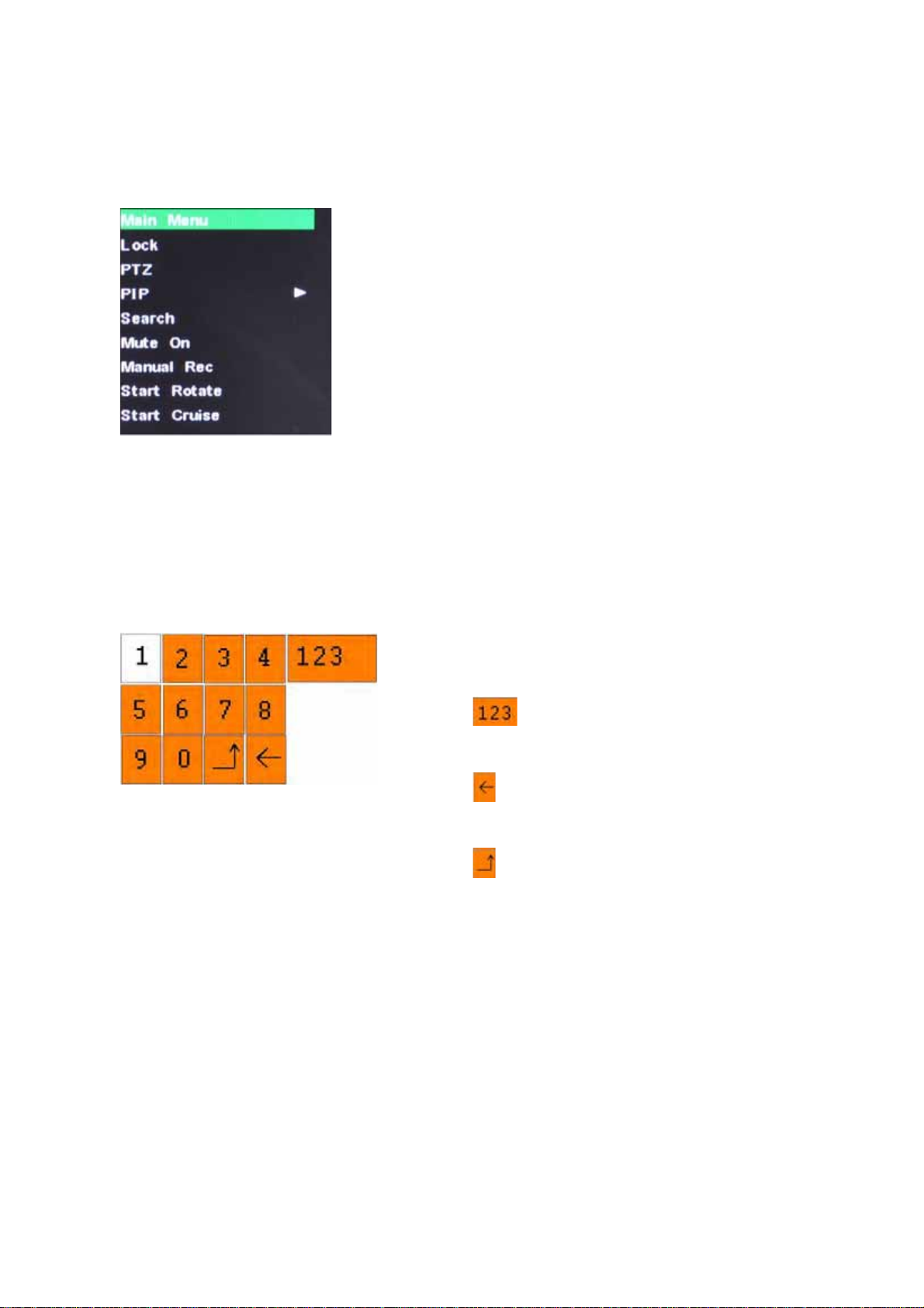
To open the Sub-Menu, Right-click anywhere onscreen to open Sub-Menu.
MAIN MENU: Opens the main system menu
Lock: Password protect access to menu and options
PTZ: Opens the PTZ control menu
PIP: Choose between showing one or two small pictures within
the main display picture.
Search: Open the Search Menu to view recorded video
Mute On: Select to mute audio
Manual Rec: Select to start manual recording.
START ROTATE: Start sequential display
START CRUISE: PTZ cruise settings.
To close the Sub-Menu, click anywhere onscreen.
Using the Virtual Keyboard – Mouse Only
User’s Manual
When using the mouse, you can input certain values using the onscreen virtual keyboard.
You will need to use the Virtual Keyboard when entering your User ID and Password.
To use the Virtual Keyboard:
1. Click on an option or field, such as the User ID and
Password fields.
2. Click 0~9 to enter the desired digit.
3. Click
to switch between numerals, upper and
lowercase letters, and other characters (only for
certain options)
4. Click to Backspace/Delete.
NOTE: The buttons will turn from orange to white
when you select the button with the mouse cursor.
5. Click to enter/confirm and close the Virtual
Keyboard.
14

6.1 Main Menu Preview
User’s Manual
MAIN MENU
Record
Functions
Playback
Network
Camera
Record
Motion
Alarm Setup
Internet / LAN
Mobile
E-mail Setup
Camera Settings
PTZ
Date/Time
System
Password
Language
Advanced
Hard Drive
A/V Setup
Maintain
Info
15
 Loading...