


INSTALLATION AND OPERATION MANUAL
Version 08/04
© Copyright 2004 Incredible Technologies, Inc. All Rights Reserved.

WARNINGS AND NOTICES
NOTICE
This game is intended to be operated for amusement purposes only. It is not to be operated in violation of any federal, state, or local
laws or regulations. As the owner and/or operator of this game you are responsible for its operation in compliance with such laws
and regulations. The factory settings for this game may require adjustment in order to comply with the laws and/or regulations in the
jurisdiction where the game is located. It is the sole responsibility of the operator to determine what laws and/or regulations are
applicable and to make any adjustments to the game before operating it for its intended purpose.
NOTICE
This manual and the information contained within is subject to change without notice.
WARNING
Use of unauthorized parts or making any unauthorized modifications will void the warranty and may result in the game operating in
an unsafe or incorrect manner.
WARRANTY, REPAIR, AND RETURN POLICY
• 90-day warranty on all electronic components. All warranty periods begin on the date of purchase from Incredible
Technologies, Inc.
• There is a minimum $55.00 service charge for all non-warranty repairs or returns.
• For all servicing, return to Incredible Technologies, Inc.
• ANY non-factory repair or attempted repair voids warranty.
RETURN MERCHANDISE AUTHORIZATION
• All returned merchandise must have a Return Merchandise Authorization (RMA) number marked clearly on the outside of the
package.
• You must obtain all RMA numbers from Incredible Technologies. Please have the product's Cabinet Identification Device
number available when calling for an RMA number.
• Merchandise returned without an RMA number will not be accepted.
• Warranty may be void if serial number or security labels are tampered with or removed. Opening the Nighthawk Chassis
system will void your warranty.
• Advance replacement hardware will be shipped to the customer address on file unless specified otherwise.
• Advance replacement hardware will be billed to the customer until Incredible Technologies, Inc. receives the returned
merchandise, at which time a credit will be issued.
• All repairs and/or replacements will ship as soon as possible after receipt or request (subject to availability).
If the original purchaser discovers any physical defect in the media (disk, EPROM, tape) on which the software is distributed or in
the documentation, which in the opinion of Incredible Technologies, Inc. (IT) prevents the product from being used as reasonably
intended, IT will replace the media or documentation at no charge. The purchaser must return the item to be replaced, with proof of
purchase, to IT within 90 days after taking delivery of the software.
IT warrants to the original purchaser that the hardware product is in good working condition for a period of 90 days from taking
delivery of the product. Should this product, in IT's opinion, malfunction within the warranty period because of a defect in design,
materials, or workmanship, IT will repair or replace this product without charge under the terms as follows. Replacement of either
the hardware product or its component parts will be only on an exchange basis. Any replaced parts or components become the
property of IT. This warranty does not apply to those products that have been damaged due to accident, abuse, improper
installation, natural disaster, or unauthorized repairs or modifications.
IT excludes any and all implied warranties, including warranties of merchantability and fitness for a particular purpose, and limits the
purchaser's remedy to returning the software, hardware, or documentation to IT for replacement.
IT makes no warranty or representation, either express or implied, with respect to this software, hardware, or documentation, their
quality, performance, merchantability, or fitness for a particular purpose. This software, hardware, and documentation are licensed
"as is," and the purchaser/licensee assumes the entire risk as to their quality and performance.
In no event will I T be liable for direct, indirect, special, incidental, or consequential damages arising out of the use or inability to use
the software, hardware, or documentation, even if advised of the possibility of such damages. The warranty and remedies set forth
above are exclusive and in lieu of all others, oral or written, express or implied. No person, seller, dealer, agent, or employee is
authorized to make any modification or addition to this limited warranty.
Some states do not allow the exclusion of implied warranties or liability for incidental or consequential damages, so the above
limitation or exclusion may not apply to you. This warranty gives you specific legal rights, and you may also have other rights that
vary from state to state.
- INCREDIBLE TECHNOLOGIES, INC
SILVER STRIKE BOWLING™, ITS®, INCREDIBLE TECHNOLOGIES®, IT®, ITNet®, and IT incredible TECHNOLOGIES® are the properties of
© Copyright 2004 Incredible Technologies, Inc. All Rights Reserved. Unauthorized duplication is a violation of applicable law.
All other marks are the properties of their respective owners. All rights reserved.
Incredible Technologies, Inc. All Rights Reserved.

Congratulations!
Congratulations on purchasing Silver Strike Bowling from Incredible Technologies!
For ease of use this manual has been broken down into four main sections:
Installing Silver Strike Bowling as a Kit - Page 3.
Silver Strike Bowling as a Dedicated game - Page 17.
Operator Menus - Page 21.
Troubleshooting and Reference - Page 39.
A more complete table of contents can be found on the next page.
Silver Strike Bowling Features
Ø Up To 8 Players Can Play Together
? Players have their own unique bowling ball and shirt color!
Ø Choose Male Or Female Bowlers
? Each of the 8 player colors includes a male and female version!
Ø Series Play (3 Games Per Player)
? Now, just like in a bowling league, players can play three games in a row and receive a series score!
Ø Unique Trackball Control Simulates Realistic Delivery and Ball Paths
? Get the feel of a real bowling hook with our amazing trackball control!
Ø 5 Selectable Ball Weights
? Players can choose between a 12, 13, 14, 15, or 16 pound ball just like in a real alley!
Ø "Vegas Bowling" Mode Promotes Competition
? A little friendly competition is inspired with this additional feature that's pure fun!
Ø Real-Time Pin Action & Ball Physics
? Pins fall before your very eyes just as they would in the lanes!
Ø TV Quality Instant Replays
? Want to see that amazing shot again? Now you can with our instant replay feature!
Ø Interactive Player Camera Control for Exciting 3D Effects
? Changing the camera gives you a new 'view' on all the action!
Ø Powerful New Hardware Platform
? Silver Strike Bowling leaps into the future with new hardware that ramps up the fun!
Ø Stunning 3D Graphics and Effects
? Players of all skill levels will enjoy the realistic feel and dynamic 3D graphics.
It’s tenpin bowling brought to an all new level of energy and excitement!
This game is rated SUITABLE FOR ALL AGES.
Silver Strike Bowling™ Version 08/04 Page 1
© Copyright 2004 Incredible Technologies, Inc. All Rights Reserved. Unauthorized duplication is a violation of applicable law.
All other marks are the properties of their respective owners. All rights reserved.

TABLE OF CONTENTS
CONTENTS PAGE CONTENTS PAGE
WARNINGS AND NOTICES (Inside Cover) I
FEATURES 1 Hardware/Software 28
TABLE OF CONTENTS 2 System Info 28
KIT INSTALLATION SECTION 3 USB Info 29
Kit Package Contents 4 Version Info 29
Recommended Tools 6 Check Hard Drive 29
Installation Preparation 6 Check Cooling 30
THE CABINET 7 Silver Strike Settings 30
Cabinet Selection 7 Player Cost Schedule 31
Preparing the Ca binet for Installation 7 Value Reset – Player Cost Schedule 31
Monitor Requirements and Clean-Up 7 Game Audits 32
GAME ELECTRONICS 8 Money Audits 32
I/O Board Installation 8 Value Reset – Collections & Audits 32
I/O Board Diagram 9 Game Purchase Audits 33
Additional Monitor Instructions and Diagram 9 Value Reset – Collections & Audits 33
Nighthawk Chassis Installation 10 Ticket Dispenser Audits 33
Nighthawk Chassis Diagram 10 Value Reset – Collections & Audits 34
Cabinet Identification Device Installation 11 Value Reset - Collections & Audits 34
Ticket Dispenser 11 Game Options 34
CONTROL PANEL 11 Value Reset – Game Options 35
Trackball Preparation 12 Game Event Info 35
Button Preparation 12 Value Reset – Game Event Info 35
Control Panel Overlay Installation 12 Value Reset – Reset Leaderboards 36
Finishing the Control Panel 13 Ticket Dispenser 36
FINISHING THE KIT 14 Dispenser Settings 36
Side Decal Installation 14 Value Reset – Dispenser Settings 37
Marquee Installation 14 Ticket Settings 37
Dip Switch Settings 15 Value Reset – Ticket Settings 38
Coin Door, Test Switch, Volume Control Panel 15 Clear Tickets Owed 38
INITIAL KIT POWER-UP 15 Value Reset – Clear Tickets Owed 38
DEDICATED CABINET SECTION 17 TROUBLESHOOTING AND REFERENCE 39
THE CABINET 18 Appendix A 40
Dedicated Cabinet Contents 18 Video Problems 40
Test/Volume Buttons 18 Sound Problems 41
Monitor 18 Control Problems 41
Security Bar 18 Nighthawk Chassis Problems 42
Ticket Dispenser 18 Error Messages 42
Dip Switch Settings 19 Miscellaneous Problems 42
INITIAL DEDICATED POWER-UP 19 Appendix B 43
OPERATOR MENUS SECTION 21 JAMMA Harness Connection 43
Main Menu 22 Trackball Harness Connection 43
Value Reset – Collection & Audits Reset 22 I/O Board Power Cable Pin Out Diagram 43
General Settings 23 Nighthawk Chassis Diagram 44
Operator Adjustables 23 I/O Board Diagrams (Kit/Dedicated) 44
General Adjustments 23 Detailed Cable Connection Diagram 45
Value Reset – General Adjustments 24 SSB Cabinet Wiring Diagram 46
Money Slot Adjustments 24 Appendix C 47
Value Reset – Money Slot Adjustments 24 GAME ICON DESCRIPTIONS 47
Sound Adjustments 25 Cooling Icon 47
Value Reset – Sound Adjustments 25 Tickets Owed Icon 47
Value Reset – Reset To Factory Settings 25 TRACKBALL/BUTTON TEMPLATES 47
System Tests 26 Control Panel Diagram 47
Video Tests 26 Trackball Mounting Template 49
Color Adjustments 26 Trackball Orientation Diagram 51
Contrast Adjustments 27 Right Buttons Template 53
Sound Tests 27 Left Buttons Template 53
Mechanical Meter 27 Appendix D 55
Silver Strike Bowling™ Version 08/04 Page 2
© Copyright 2004 Incredible Technologies, Inc. All Rights Reserved. Unauthorized duplication is a violation of applicable law.
All other marks are the properties of their respective owners. All rights reserved.
Replacement Part Numbers 55
Contact Information II
IT Sales and Service Information II
IT Vendor Information II
Hardware Tests 28

Silver Strike Bowling
Kit Installation
Silver Strike Bowling™ Version 08/04 Page 3
© Copyright 2004 Incredible Technologies, Inc. All Rights Reserved. Unauthorized duplication is a violation of applicable law.
All other marks are the properties of their respective owners. All rights reserved.

Kit Contents (Including Part Numbers)
Please refer to these IT part numbers when placing orders.
Included in the Silver Strike Bowling Kit (Part # 925000265) should be the following:
A bag of parts is included in your kit and the contents can be found on the next page.
Silver Strike Bowling™ Version 08/04 Page 4
© Copyright 2004 Incredible Technologies, Inc. All Rights Reserved. Unauthorized duplication is a violation of applicable law.
All other marks are the properties of their respective owners. All rights reserved.
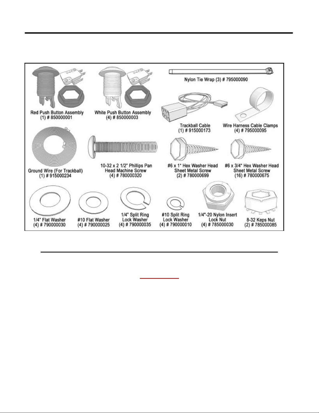
Kit Contents (Including Part Numbers) - Continued
Keep in mind most of these basic parts like screws/washers can be found at any hardware store.
Please refer to these IT part numbers when placing orders.
Your bag of parts (Part # 9002650 30) should include (at least):
NOTE: PLEASE RETAIN ORIGINAL SHIPPING BOX FOR SERVICE AND REPAIR.
NOTE
This kit is designed for use in cabinets with
JAMMA cable and wiring installed.
If you do not have a JAMMA harness already
installed in the cabinet you have selected and are
wiring the cabinet yourself, refer to the JAMMA
Wiring Diagram on page 43 in this manual.
Silver Strike Bowling™ Version 08/04 Page 5
© Copyright 2004 Incredible Technologies, Inc. All Rights Reserved. Unauthorized duplication is a violation of applicable law.
All other marks are the properties of their respective owners. All rights reserved.

Recommended Tools
Have the following tools ready before you begin to install this kit:
q ¼" Nut Driver
q 7/16" Socket or Driver
q 11/32" Socket
q Phillips Head #2 Screw Driver
q 9/32" Drill OR 5/16" and ¾" Drill Bits
q 1 1/8" Hole Saw or Drill Bit
q Small Flat Blade Screwdriver
q Jig/Sabre Saw
q Router
q Push Button Nut Socket or Large Adjustable Pliers
q X-acto® Knife or other Sharp Knife/Razor Blade
q Wire Cut ters
q Scissors
q Tape Measure
q Putty Knife
q Decal Roller/Squeegee
q Liquid Window Cleaner & Cleaning Cloth
q Vacuum Cleaner
q Any tools needed to remove parts from your existing cabinet not listed above.
Many operators notice their earnings increase with touches as simple as a fresh coat of paint and a clean cabinet.
If you will be painting, you'll need these supplies:
q Air Brush or Paint Sprayer,
q Paint Brush, Paint Roller, and Pan
q Paint (and Primer) --We recommend black as a cabinet color choice.
q Sandpaper
Installation Preparation
BEFORE YOU START…
Before you install the Silver Strike Bowling kit into your cabinet there are a few things you should check first:
1. Check to make sure your existing cabinet's monitor, speakers, AC power cord, and lights work.
q Replace or repair where necessary.
2. Check to make sure all the necessary parts are included in your kit.
q If any are missing/damaged please contact IT's Technical Support at 847 -870-7027 x121.
3. Check to make sure cabinet is wired with standard earth grounded A.C. plug compatible with local
building codes and/or safety requirements.
q If not, have a qualified electrician install one (not provided).
4. Have all the necessary tools available to install this kit.
q Refer to the recommended tools list above to make sure you are pr epared before you start.
5. Make sure any parts of the system (lights, monitor, etc.) are not plugged in.
q Working with any part of the system plugged in or powered on can be dangerous.
6. Keep in mind that it's been proven that the higher quality of work put int o a kit installation results in a
higher earning game.
q Make sure you have plenty of space, time, and focus to put into this kit installation.
Silver Strike Bowling™ Version 08/04 Page 6
© Copyright 2004 Incredible Technologies, Inc. All Rights Reserved. Unauthorized duplication is a violation of applicable law.
All other marks are the properties of their respective owners. All rights reserved.

The Cabinet
Cabinet Selection
You can choose either a new cabinet or a used cabinet for your Silver Strike Bowling game. Reusing a cabinet is
by far the most cost-effective way to maximize the return on your initial investment. In either case, all you need to
provide is the cabinet with a monitor, JAMMA harness, coin and bill acceptors, working fluorescent/marquee
lights, and speakers. We provide the rest. The end result is a new game at a very low cost.
When selecting a cabinet, keep in mind that a large control panel allows you to mount the trackball farther from
the monitor. This prevents players' hands from hitting the monitor glass when rolling the trackball forward, and will
earn better than a smaller control panel closer to the monitor.
Preparing the Cabinet for Installation
Follow these steps to prepare your cabinet before installation:
1. Remove the following from the cabinet: Main Logic Board(s) (and hard drive if present), Control
Panel, Monitor Viewing Glass, Marquee, and Power Supply.
2. Thoroughly clean out your cabinet. Remove all of the old buttons, joysticks, etc. DO NOT remove
monitor and speaker wires or the wires that were previously hooked up to the control panel.
3. Remove the old graphics and adhesive from the cabinet including the control panel.
4. For a fresh look and best earnings painting is highly recommended. Spray painting gives a better
finish, but if an air brush or paint sprayer is unavailable a roller is second best. Remember to cover all
exposed surfaces not to be painted. When not installing into an old Golden Tee® dedicated cabinet,
the recommended color choice is black.
5. Make sure to have the sides of the cabinet and the control panel as smooth and flat as possible to
allow for a higher quality finish when applying the control panel background, labels, and side decals.
6. The "new game look" should always apply to the inside of your game as well. A few wire ties and
shrink tubing on your harness, some fastening hardware on your subassemblies, and a sweep with
Monitor Requirements and Clean-Up
Silver Strike Bowling has been designed to operate with SVGA (800 x 600), VGA (640 x 480), medium resolution
(512 x 384) and low resolution (340 x 255) monitor systems. For best results choose a cabinet with a SVGA
compatible monitor.
When operating with a SVGA or VGA monitor, Silver Strike Bowling uses the standard VGA sync timing and
signals. When operating with medium resolution or low resolution monitors, Silver Strike Bowling operates with
composite negative serrated sync.
NOTE: In all cases a horizontal mount raster scan monitor is required.
Silver Strike Bowling has been designed to run at multiple screen resolutions. Operating Silver Strike Bowling at
the highest possible resolution will give your game the best results (and revenue). Many current games use
medium-res. and VGA/SVGA monitors already. If you have a low-res. monitor, it may be possible to switch it to a
higher resolution. Check your monitor's manual for availability.
CAUTION! Monitors are extremely dangerous and can result in severe injury. Make sure you follow and observe
all safety precautions as outlined in your monitor's manual.
ALWAYS disconnect the power to the cabinet before working on or around the monitor.
Now is a great time to clean both sides of the monitor viewing glass and monitor screen to ensure a clear view of
the game. Once you have done so reinstall the monitor viewing glass back in place.
the vacuum cleaner will help ensure that glitches do not occur.
Silver Strike Bowling™ Version 08/04 Page 7
© Copyright 2004 Incredible Technologies, Inc. All Rights Reserved. Unauthorized duplication is a violation of applicable law.
All other marks are the properties of their respective owners. All rights reserved.
Game Electronics
SW201 Video Dipswitch Settings 0 = OFF 1 = ON
I/O Board Installation
NOTE: Before installing any electronics make sure cabinet power switch is in the OFF position and the cabinet
power is unplugged from the wall.
Silver Strike Bowling comes with a specially designed I/O board that works with your cabinet's already installed
JAMMA harness. The I/O board is used as a connection interface between the JAMMA and the Nighthawk
Chassis. Refer to the diagram on page 9.
1. Mount the I/O board into the cabinet using 6 of the 6 x ¾" Hex Washer Head Sheet Metal Screws. The
existing JAMMA harness edge connector will attach to this board.
2. Cable connections:
q JAMMA Connector. Be sure it fits tightly.
q Trackball Cable to the Trackball connector. Other end will connect to the trackball.
q Power cable to the power input connector. Use the end with the 4-pin pigtail. Other end connects to
the Nighthawk Chassis.
q USB cable to the USB port. Other end connects to the Nighthawk Chassis.
q Audio Cables to the I/O board audio inputs. Other ends will connect to the Nighthawk Chassis.
q Video cable (SVGA) in from Nighthawk Chassis. Low or medium resolution monitors only. See
diagram on page 9. VGA or SVGA monitors are connected directly to the Nighthawk Chassis video
output. See diagram page 45.
3. Coin door wiring. Note: There is no power source at the JAMMA connector. Power for coin door lights can
be sourced at the Power Cable pigtail.
q Wire ground and appropriate power to the coin door lights. Depends on type of bulbs in your cabinet.
q Coin input switches and bill acceptor common ground wired from JAMMA ground. See pin out
diagram on page 43.
q Coin input signal wires to coin switches normally open post and bill acceptor signal out. See pin out
diagram on page 43.
4. Coin meter wiring.
q +12 volts or + 5 volts to one lead of the coin meter.
Depending on the device specifications.
q Coin count 1 signal wire from JAMMA to the other lead
of the meter. See pin out diagram on page 43.
5. Dip Switch SW201 set according to the type of monitor you are using.
Power Cable, I/O Board Pin Out
Pin Number Wire Color Function
1 Yellow + 12 Volts DC
2 Black Ground
3 Red + 5 Volts DC
4 Black Ground
Position
4 3 2 1
0 0 0 1 1 640 X 480 31.5 KHz VGA Direct from Chassis, See Diagram on Page 45
0 0 1 0 2 800 X 600 37.8 KHz SVGA Direct from Chassis, See Diagram on Page 45
0 1 0 0 4 340 X 255 15.75 KHz Low Resolution Through I/O board, See Diagram on Page 45
0 1 0 1 5 512 X 384 25 KHz Medium Resolution Through I/O board, See Diagram on Page 45
Video
Mode
Resolution Scan Rate Monitor Video connection
6. Cable Clamp. Mount near the I/O board aligned with the power connector so that you can have the USB
cable pulled towards the board. This keeps the USB cable from
accidentally being jostled out of its slot. Use this clamp to keep
other loose wires neat. Use wire ties where needed.
7. Speaker Wiring. SSB audio default setting is mono. Wire your
speaker(s) to the left or right channel audio outputs on the
JAMMA, Pins 10 and J or 11 and K respectively. If you want to
operate SSB in stereo mode, both the left and Right Channels
need to be connected. If audio out is set to stereo, you must
have a speaker wired to each channel, plus to plus and minus to
minus. If not wired properly you will not hear all of the sounds
which may compromise game earnings.
8. Control panel buttons. See Finishing The Control Panel (page 13)
for control panel layout, and JAMMA pin out chart (page 43).
Silver Strike Bowling™ Version 08/04 Page 8
© Copyright 2004 Incredible Technologies, Inc. All Rights Reserved. Unauthorized duplication is a violation of applicable law.
All other marks are the properties of their respective owners. All rights reserved.
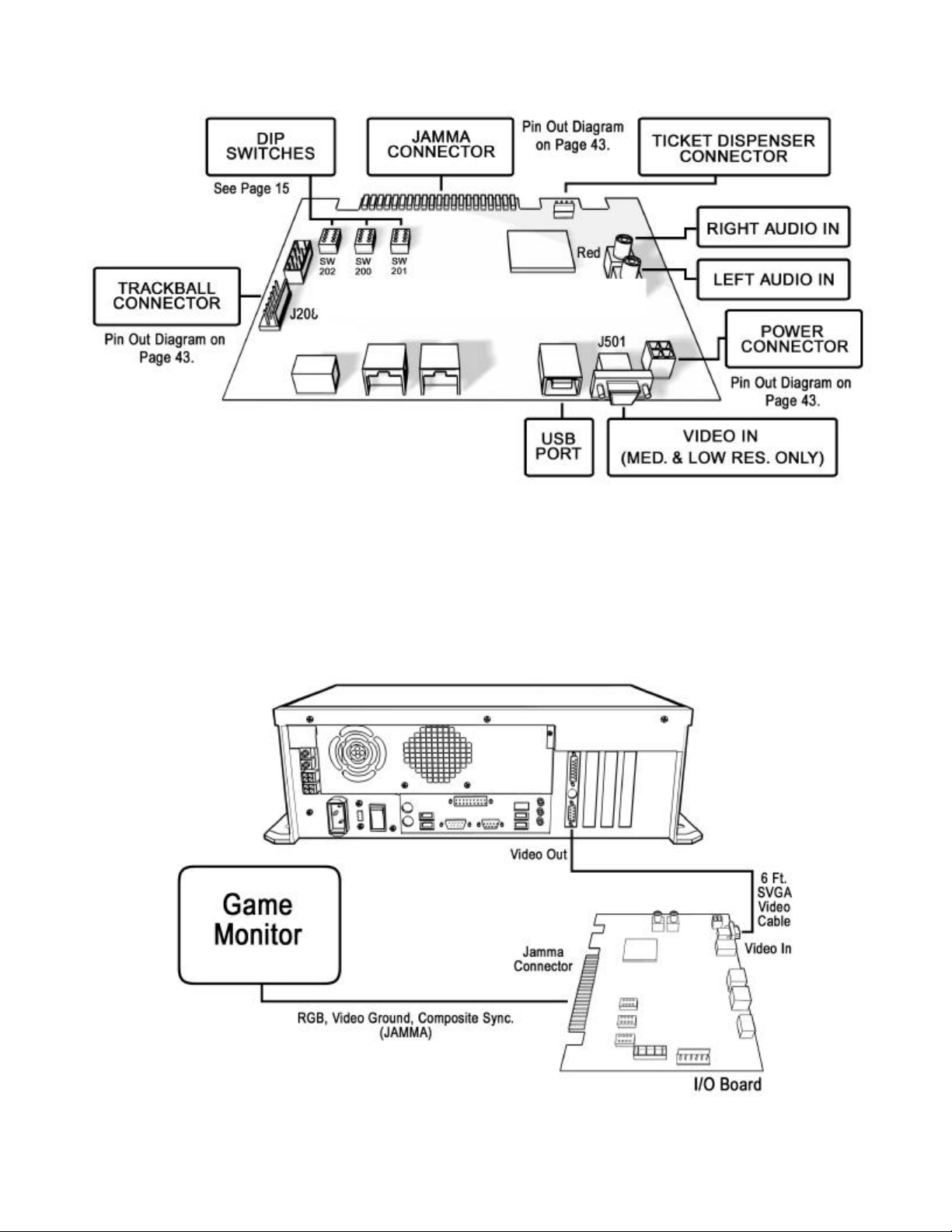
Please refer to the following diagram as well as a detailed diagram on page 45 for correct placements when
connecting cables to the I/O board:
Additional Instructions For Low or Medium Resolution Monitors:
To connect to a low or medium resolution RGB monitor refer to the figure below:
1. Connect one en d of the 6 ft. SVGA video cable to the video out of the Nighthawk Chassis.
2. Connect the other end of the 6 ft. SVGA cable to the I/O board video in J501.
3. Connect the Red, Green, Blue video outputs, the composite sync, and video ground to the appropriate
monitor inputs. To find the correct JAMMA pin outs refer to the diagram on page 43.
Silver Strike Bowling™ Version 08/04 Page 9
© Copyright 2004 Incredible Technologies, Inc. All Rights Reserved. Unauthorized duplication is a violation of applicable law.
All other marks are the properties of their respective owners. All rights reserved.
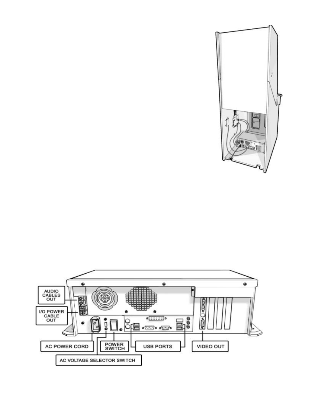
Nighthawk Chassis Installation
The Nighthawk Chassis houses most of the game electronics and hardware
into one box that can be easily installed. Verify that the Nighthawk Chassis
Power Switch is in the "ON" position.
1. Locate the area on the floor where the chassis will be placed. Make
sure there is enough clearance to plug in cables.
q The Nighthawk Chassis measures 19" W x 7" H x 11" D.
2. Relocate and sec ure any wires to make room for the chassis.
3. Place the chassis so it sits flat on the floor and does not pinch wires.
4. Mount the chassis with 6 - #6 x ¾" Hex Washer Head Sheet Metal
Screws.
5. Cable Attachments. I/O power, Audio, USB cables. Refer to page 45.
q I/O board power cable from the I/O board to one of the two power
output connectors on the chassis.
q Audio cables to the audio output jacks of the chassis. Match the
appropriate colors.
q USB cable #1 from the I/O board to any USB port on the chassis.
q USB cable #2 for future updates. Attached to any USB port on the
chassis. Route the other end near the coin door opening for easy
access.
q USB cable #3 Cabinet Identification Device (C.I.D.) connect to any
USB port on the chassis. See C.I.D. Installation Section. (Page 11)
6. VGA Video Cable Attaches to the video out on the chassis to…
q I/O board video in for Low or Medium Resolution monitors.
q VGA or SVGA monitors, Directly to the VGA or SVGA monitor input.
q See Dip Switch settings on page 15 for proper set up.
7. AC powe r cord plugs into the Chassis. Have a qualified electrician do the wiring. Verify A.C. main voltage
selector switch is in the proper position. In North America the setting is 115 volts AC. In some countries
this should be set at 230 VAC.
8. Use cable clamps, with appropriate tension, where necessary to ensure all cables stay in place during
operation.
9. Dress all cables with additional clamps and wire tie wraps where needed.
Refer to the diagrams on this page as well as a detailed diagram on page 45 for cor rect placements of Nighthawk
Chassis, C.I.D., and cables from the Chassis to I/O board to peripherals:
Silver Strike Bowling™ Version 08/04 Page 10
© Copyright 2004 Incredible Technologies, Inc. All Rights Reserved. Unauthorized duplication is a violation of applicable law.
All other marks are the properties of their respective owners. All rights reserved.
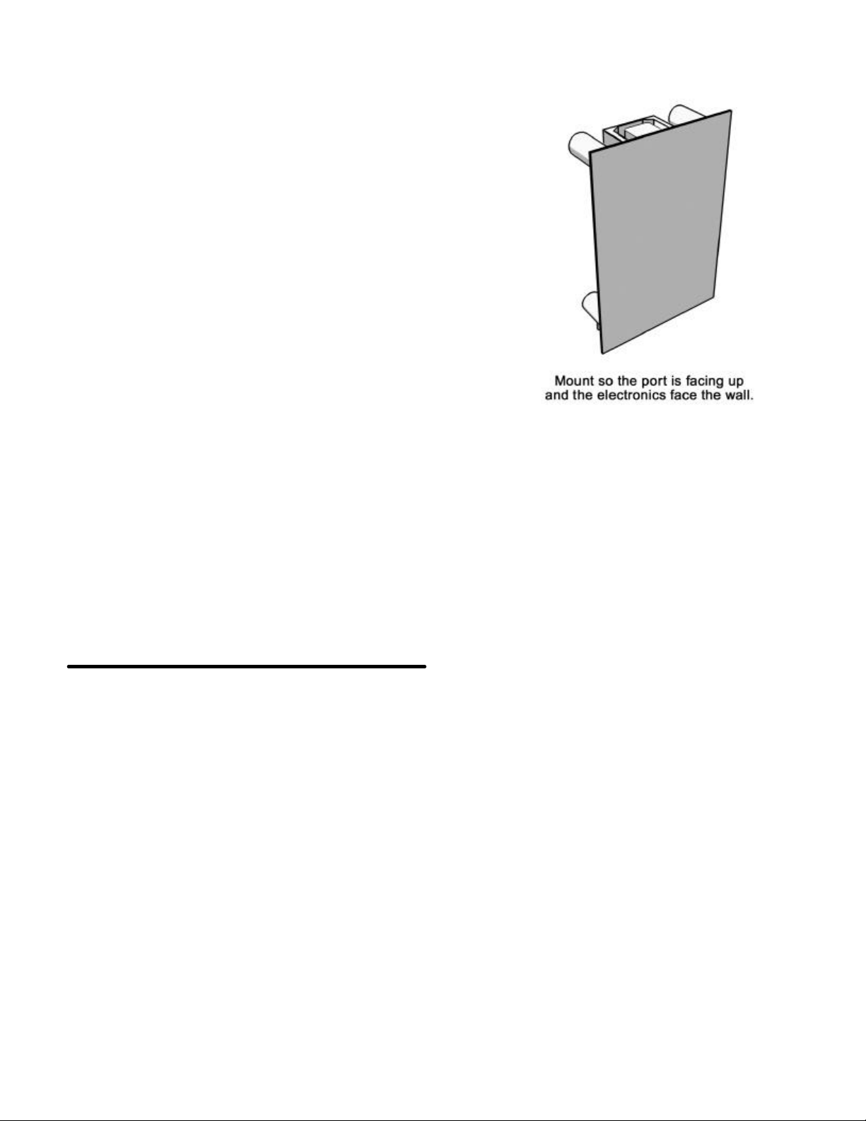
Cabinet Identification Device Installation
The Cabinet Identification Device or C.I.D. is an innovative and
important component. This de vice permanently identifies your
cabinet as Silver Strike Bowling. It should remain even if another
component such as the I/O board or chassis is replaced. The C.I.D.
has a unique number to individualize the cabinet and is referred to
as the Cabinet Identification Number.
1. Attach the C.I.D. to the inside side of the cabinet using the
2 - #6 X 1” Hex Washer Head Sheet Metal Screws. Mount
so the port is facing up and the electronics faces the wall.
2. Attach the USB cable from the Nighthawk Chassis.
Ø Place the included Cabinet Identification Number on the
back of the cabinet for future reference. Refer to this
number to track your equipment and whenver you
are calling in for service.
Ø The Cabinet Identification Number is displayed in the
operator menus in the lower right hand corner. It is
displayed as Game ID. It is also displayed on the last
line of the initial boot -up screen.
Ticket Dispenser
Silver Strike Bowling supports Entropy 2000 Ticket Dispenser Continuous Type (TD963CR) and Deltronic Labs
DL-1275 Cont inuous Type ticket dispensers. If you wish to connect a ticket dispenser to this game, you will have
to make a cable with the proper connectors. These ticket dispensers mates with a Molex connector #03 -09-1041
or #03-09-1042. The I/O board ticket connec tor J201 mates with a Molex connector #22-01-2047 or #22-01-
3047. Simply connect pins 1 through 4 on one end directly to pins 1 through 4 on the other end. Consult with your
ticket dispenser's manual to verify installation procedures. (See the Ticket Dispener section in the Operator
Menus starting on page 36.)
Control Panel
Trackball and Button Preparation
Mounting the trackball and buttons correctly and securely is very important for the profitability and safety of your
new game. This kit is designed for use in cabinets with ¾" thick wood control panels where proper routing of the
control panel is used to create a safe playing experience. If you do not have a ¾" thick wood control panel, please
replace your control panel or choose a cabinet with a ¾" thick wood control panel installed. Keep in mind that if
your current control panel has many old holes in it from previous buttons, joysticks, etc. that it may be easier to
start with a new solid control panel. This will give your game a better look and feel and help it to earn better.
NOTE: If the cabinet already has a trackball plate installed, discard and replace with the new trackball plate. The
metal trackball mounting plate and trackball mounting procedure have been designed to remove all bolts from the
playing surface. Routing the wood control panel is required so the metal mounting plate is flush with the panel
surface. An uneven playing surface or exposed edges will affect game play and could impact your earnings.
TIP: Trackball and button templates can be found at the back of this manual. They include:
q Trackball Template to install the trackball plate and make the appropriate routing (page 49).
q Trackball Orientation Diagram to orient your trackball correctly when installing (page 51).
q Button Set Templates to position and install control panel buttons (page 53).
Silver Strike Bowling™ Version 08/04 Page 11
© Copyright 2004 Incredible Technologies, Inc. All Rights Reserved. Unauthorized duplication is a violation of applicable law.
All other marks are the properties of their respective owners. All rights reserved.

Trackball Preparation
Install the metal trackball plate by following these steps:
1. Cut out the template (see template-page 49) with a pair of scissors along the noted line. Tape this
template to the top of the control panel as far away from the monitor as possible, making sure that the
trackball will clear the cabinet beneath it. NOTE: Installing the trackball as far away from the monitor as
possible will prevent players' hands from hitting the monitor glass when rolling the trackball forward.
2. Using a sharp object, mark the eight points shown on the template on the control panel. Using a pencil,
trace the outside of the template. Remove the template.
3. Drill Holes 1-4 with a 9/32" or 5/16" drill bit.
4. Drill Holes 5-8 with a ¾" drill bit.
5. Route the crosshatched region to a depth of about .075" (about the thickness of a nickel).
6. Using a sabre saw cut out the center portion by cutting between holes 5-8.
7. Once you have cleaned up the routed area, ins tall the trackball plate into the control panel using the ¼"
Flat Washers and ¼-20 Nylon Hex Nuts. Be sure the mounting plate is flush with the top of the control
panel.
NOTE: At this time you are only installing the trackball plate, do not install the trackball yet.
Button Preparation
The following are the steps you should take to prepare your control panel for the installation of the button
assemblies:
1. Cut out the template(s) (see template-page 53).
2. Cut along the dotted line to separate the templates .
3. Using a tape measure, measure the specified distances from the center of the trackball hole in the
trackball plate and make a mark for both the left and right button reference points.
4. Lay each template over the appropriate reference marking point. Mark the centers of the remaining holes
using a sharp object.
5. Drill a 1 1/8" hole at each marked point.
NOTE: Do NOT install the trackball or buttons until the control panel graphics have been applied.
Control Panel Overlay Installation
Silver Strike Bowling comes with an oversized control panel overlay that will accommodate a variety of existing
game cabinets, but works best on Golden Tee Fore®, NFL® Blitz™ and EA Sports™ PGA Tour® Golf cabinets.
Follow these instructions to correctly install the control pa nel overlay on one of these cabinets:
1. Make sure that the newly drilled control panel has a smooth, clean surface. Sand where necessary to
make sure the graphics are installed on an even surface.
2. Clean the control panel to make sure it is free from dust, grease, metal filings, etc. Make sure that all
residues (adhesive, overlay material, etc.) from the previous control panel graphics are removed. This
will ensure a clean, easy, and beautiful application of the control panel graphics.
3. It is very important that the trackball and control panel graphics be mounted perfectly straight.
Find the center of your trackball template and lightly draw vertical and horizontal guidelines on the control
panel, marking out your centering lines.
4. Remove a small section of the protective backing from the overlay. Carefully center the overlay over the
control panel by lining up the die -cut hole with the trackball template. Be sure the graphic is positioned
perfectly straight. Line up your pencil guidelines with the lines incorporated into the art. Once in
position, gently press down on the section with exposed adhesive, affixing the overlay into place. Once
affixed, the overlay cannot be removed.
Silver Strike Bowling™ Version 08/04 Page 12
© Copyright 2004 Incredible Technologies, Inc. All Rights Reserved. Unauthorized duplication is a violation of applicable law.
All other marks are the properties of their respective owners. All rights reserved.
Control Panel Overlay Installation - Continued
5. While holding down the overlay over the attached area, very carefully turn over one side and remove the
exposed backing. Gently lay down the exposed overlay from the center outward, smoothing with your
hands or a roller as you go. Be sure the overlay remains straight and square. Repeat the process
with the other side of the overlay, so the entire surface is affixed to the control panel. Make sure all
bubbles have been pressed out for a clean, flat surface.
TIP: Liquid window cleaner can be sprayed onto the control panel before placing the overlay onto
the control panel. The window cleaner will allow the overlay to be positioned with less risk of
damage to the overlay or adhesive. Once in position, use a decal roller or squeegee to force any
excess cleaner out. Be sure to add additional time for the adhesive to cure.
6. Using an X-acto knife (or other sharp instrument) carefully cut around the edges of your control panel,
trimming any excess material.
7. Find the center of each hole you've drilled out for the buttons and use the knife to poke a hole into the
overlay. Make a vertical and horizontal line (like a plus sign) from the center of the hole to the edges. You
should be able to place your button in later with no edges showing.
CAUTION: If you choose to install a Plexiglas® cover over your control panel (not recommended), to ensure the
safety of your players and the quality of your game make sure that all surfaces, edges and bolts that a player may
come in contact with are smooth, safe and secure.
Finishing The Control Panel
1. Reattach the control panel to your cabinet adjusting any hinges or chains where necessary. Make sure
not to pinch or crimp any wires while re-attaching the control panel.
2. Install the trackball to the trackball plate. The trackball must be oriented correctly in order to function
properly. Refer to the diagram located on page 51 for correct orientation. You will need the following parts
in order to install the trackball correctly to the plate: 4 -10/32 x 2½" Phillips Head Machine Screws, 4 - #10
Flat Washers and 4 - #10 Split Lock Washers NOTE: Do not over-tighten the trackball. It will warp and
cause the trackball to not operate correctly.
IMPORTANT! Be sure to install your trackball securely, and maintain it regularly. Loose, worn, or
incorrectly mounted trackballs can result in decreased earnings and possible injury to players.
3. Secure the trackball ground wire to the trackball plate at the 8-32 stud on one end with an 8-32 KEPS nut
and the other end to the cabinet ground stud (usually located near the AC po wer cord inlet) using an 8-32
KEPS nut.
4. Install the buttons in the holes located on your control panel. Make sure you use the red button assembly
where the hole and decal for the Start button is placed.
5. Attach the micro switches to your newly installed but tons and connect the wires up to the correct pins on
the JAMMA harness.
q NOTE: The post on the switch labeled COM should connect to the ground wire and the post labeled
NO should connect to the signal wire. See the JAMMA pin out chart on page 43.
Silver Strike Bowling™ Version 08/04 Page 13
© Copyright 2004 Incredible Technologies, Inc. All Rights Reserved. Unauthorized duplication is a violation of applicable law.
All other marks are the properties of their respective owners. All rights reserved.

Finishing The Kit
Side Decals and Marquee
Included with your Silver Strike Bowling kit is a set of decals to place on the side of your cabinet and a brand new
marquee. This will help identify your new game as Silver Strike Bowling. By placing and installing these correctly it
can help give players instant recognition, even from a distance.
Side Decal Installation
The following are the instructions on placing your side decals correctly on to the cabinet:
1. Locate the place where the side decals will be viewed bes t on your
cabinet. Refer to the diagram included on the decal sheet and to the
right of these instructions for optimal placement.
NOTE: Make sure to have the sides of the cabinet as smooth and
flat as possible, removing all previous residue from prior decals, to
allow for a higher quality finish.
TIP: Liquid window cleaner can be sprayed onto the sides of the
cabinet before placing the decals. The window cleaner will allow
the decal to be removed and re-installed without damaging the
decal or adhesive. The decal roller or squeegee forces the cleaner
out, leaving just the adhesive.
2. Remove the first of the new cabinet side decals from the backing.
3. Center the first decal on the location selected for your cabinet.
4. Using your hands (or a decal roller/squeegee), press down firmly
starting from the center and smooth the side decal outward. Make sure
all bubbles have been pressed out for a clean, flat surface.
5. Repeat for each of the remaining side decals.
Marquee Installation
The following are the instructions for placing the new marquee in your cabinet:
1. Using the old marquee glass as a template, center the glass on top of your new marquee. Make sure that
all the printed images are visible.
2. Using an X-acto® knife or other sharp blade, score the new marquee de eply by following the edges of the
old glass as a guide.
CAUTION: Do not cut on table or counter top. Use a cutting board or a disposable surface.
3. Carefully break off any excess material you have cut off.
4. Be sure the light behind the marquee works.
5. Clean the glass on both sides to give players a clear view of the new marquee.
6. Install the marquee graphics and glass securely.
Silver Strike Bowling™ Version 08/04 Page 14
© Copyright 2004 Incredible Technologies, Inc. All Rights Reserved. Unauthorized duplication is a violation of applicable law.
All other marks are the properties of their respective owners. All rights reserved.

Dip Switch Settings
SW202 Dip Switch Settings 0 = OFF 1 = ON
Positions
Function
4 3 2 1
0 0 0 0 Default
1 0 0 0 Enter Operator Mode Menus
SW200 Dip Switch Settings 0 = OFF 1 = ON
Position
Function
4 3 2 1
1 1 1 1 Default - Switch Is Not Used
SW201 Video Dipswitch Settings 0 = OFF 1 = ON
Position
4 3 2 1
0 0 0 1 1 640 X 480 31.5 KHz VGA Direct from Chassis, See Diagram on Page 45
0 0 1 0 2 800 X 600 37.8 KHz SVGA Direct from Chassis, See Diagram on Page 45
0 1 0 0 4 340 X 255 15.75 KHz Low Resolution Through I/O board, See Diagram on Page 45
0 1 0 1 5 512 X 384 25 KHz Medium Resolution Through I/O board, See Diagram on Page 45
Video
Mode
Resolution Scan Rate
Monitor Video connection
Coin Doors, Test Switch, and Volume Control Panel
Wire the coin doors as pe r the JAMMA Harness Connection table on page 43. Connect the door lamps to the
appropriate (+12Vdc or +5Vdc) supply. Some games have separate power supply outputs for the lamps. Install a
test switch somewhere convenient inside the coin door area. This switch allows you to enter adjustables, run
diagnostics, and see or clear audits. Make it readily accessible through the coin door. Wire it to the Test wire on
the JAMMA Harness. Silver Strike Bowling has the ability to adjust volume at any time during a game. Install two
push button switches (not included) inside the coin door for easy access. Connect the switches to the JAMMA
harness. Refer to the JAMMA Harness Connection table on page 43.
Initial Power-Up
There are several steps you should take when powering up your Silver Strike Bowling for the first time. This is a
quick checklist for you to follow when doing your first initial power -up:
q Plug in the game and turn it ON; be sure the game powers up correctly into the attract mode.
q Adjust volume levels to desired settings.
q Adjust monitor settings for best picture.
NOTE:
Sound and Video Tests are available through the System Tests Menu. They are beneficial when
making any adjustments. (See System Tests Menu on page 26). Proper monitor and sound adjustment
is very important.
q Try all money slots. Drop quarters or tokens through to check the coin mechs and insert a bill into the
bill acceptor. Make sure the game is adding credits.
NOTE: Silver Strike Bowling supports most bill acceptors. Installing a bill acceptor is highly
recommended and will increase your earnings. Refer to your bill acceptor's manual for installation
specifications. The bill acceptor can be wired to coin door 3 on the JAMMA.
q Test all of the player input controls. You can use the PLAYER CONTROL TESTS in the SYSTEM
TESTS MENU.
q Upon initial power-up the game is set to factory default settings. These settings affect game elements
such as number of credits per coin, difficulty settings, etc. The OPERATOR MENUS section (see page
21) will describe how to alter these settings for your location.
Congratulations!
You have finished installing Silver Strike Bowling!
Silver Strike Bowling™ Version 08/04 Page 15
© Copyright 2004 Incredible Technologies, Inc. All Rights Reserved. Unauthorized duplication is a violation of applicable law.
All other marks are the properties of their respective owners. All rights reserved.

Silver Strike Bowling™ Version 08/04 Page 16
© Copyright 2004 Incredible Technologies, Inc. All Rights Reserved. Unauthorized duplication is a violation of applicable law.
All other marks are the properties of their respective owners. All rights reserved.

Silver Strike Bowling
Dedicated Version
Silver Strike Bowling™ Version 08/04 Page 17
© Copyright 2004 Incredible Technologies, Inc. All Rights Reserved. Unauthorized duplication is a violation of applicable law.
All other marks are the properties of their respective owners. All rights reserved.

Dedicated Cabinets
Dedicated Contents
(1) Silver Strike Bowling Dedicated Cabinet
(1) Silver Strike Bowling Manual
(1) Monitor Manual
(1) 4 Leg Levelers
(1) Security Bar
If any parts to your dedicated cabinet are missing/damaged
please contact IT's Technical Support at 847-870-7027 x121.
The Cabinet
NOTE: Diagrams for the Nighthawk Chassis and the dedicated
I/O Board can be found on page 44.
Volume and Test Switches
Your cabinet comes equipped with a bank of buttons mounted
inside the coin door. The Test button will enter you into the
Operator Mode Menus where audits, adjustables, and system
tests can be accessed. Refer to the Operator Menus section
(page 21) of this manual for more information.
There are also two volume control buttons mounted inside the
coin door. Press the button on the left to decre ase volume, and
press the button on the right to increase volume. You can also
adjust volume in the Operator Menus (see page 25).
Monitor
Your Silver Strike Bowling cabinet comes equipped with a digital monitor set to SVGA. Silver Strike Bowling
dedicated cabinets support high -res. monitors, offering superb graphics and brilliant colors.
Silver Strike Bowling supports low -res, mid-res., VGA and SVGA monitors. Make sure the I/O Board and monitor
are set properly for best game play results.
Security Bar
Silver Strike Bowling comes with a heavy -duty security bar, to
help you protect your cash box. Use a strong padlock (not
included) to lock the security bar in place. The security bar should
be found installed on the front of your cabinet.
Ticket Dispenser
Silver Strike Bowling supports Entropy 2000 Ticket Dispenser Continuous Type (TD963CR) and Deltronic Labs
DL-1275 Continuous Type ticket dispensers. If you wish to connect a ticket dispenser to this game, you will have
to make a cable with the proper connectors. These ticket dispensers mates with a Molex connector #03-09-1041
or #03-09-1042. The I/O board ticket connector J201 mates with a Molex connector #22-01-2047 or #22 -01-
3047. Simply connect pins 1 through 4 on one end directly to pins 1 through 4 on the other end. Consult with your
ticket dispenser's manual to verify installation procedures. (See the Ticket Dispener section in the Operator
Menus starting on page 36.)
Silver Strike Bowling™ Version 08/04 Page 18
© Copyright 2004 Incredible Technologies, Inc. All Rights Reserved. Unauthorized duplication is a violation of applicable law.
All other marks are the properties of their respective owners. All rights reserved.

Dip Switch Settings
SW202 Dip Switch Settings 0 = OFF 1 = ON
Positions
4 3 2 1
0 0 0 0 Default
1 0 0 0 Enter Operator Mode Menus
SW200 Dip Switch Settings 0 = OFF 1 = ON
Position
4 3 2 1
1 1 1 1 Default - Switch Is Not Used
Function
Function
SW201 Video Dipswitch Settings 0 = OFF 1 = ON
Position
4 3 2 1
0 0 0 1 1 640 X 480 31.5 KHz VGA Direct from Chassis, See Diagram on Page 45
0 0 1 0 2 800 X 600 37.8 KHz SVG A Direct from Chassis, See Diagram on Page 45
0 1 0 0 4 340 X 255 15.75 KHz Low Resolution Through I/O board, See Diagram on Page 45
0 1 0 1 5 512 X 384 25 KHz Medium Resolution Through I/O board, See Diagram on Page 45
Video
Mode
Resolution Scan Rate
Monitor Video connection
Initial Power-Up
There are several steps you should take when powering up your Silver Strike Bowling for the first time. This is a
quick checklist for you to follow when doing your first initial power -up:
q Plug in the game and turn it ON; be sure the game powers up correctly into the attract mode.
q Adjust volume levels to desired settings.
q Adjust monitor settings for best picture.
NOTE:
Sound and Video Tests are available through the System Tests Menu. They are beneficial when making
any adjustments. (See System Tests Menu on page 26). Proper monitor and sound adjustment is very
important.
q Try all money slots. Drop quarters or tokens through to check the coin mechs and insert a bill into the
bill acceptor. Make sure the game is adding credits.
q Test all of the player input controls. You can use the PLAYER CONTROL TESTS in the SYSTEM
TESTS MENU.
q Upon initial power-up the game is set to factory default settings. These settings affect game elements
such as number of credits per coin, difficulty settings, etc. The OPERATOR MENUS section (see page
21) will describe how to alter these settings for your location.
Congratulations! Your Silver Strike Bowling is ready for play!
Silver Strike Bowling™ Version 08/04 Page 19
© Copyright 2004 Incredible Technologies, Inc. All Rights Reserved. Unauthorized duplication is a violation of applicable law.
All other marks are the properties of their respective owners. All rights reserved.

Silver Strike Bowling™ Version 08/04 Page 20
© Copyright 2004 Incredible Technologies, Inc. All Rights Reserved. Unauthorized duplication is a violation of applicable law.
All other marks are the properties of their respective owners. All rights reserved.

Silver Strike Bowling
Operator Menus
Silver Strike Bowling™ Version 08/04 Page 21
© Copyright 2004 Incredible Technologies, Inc. All Rights Reserved. Unauthorized duplication is a violation of applicable law.
All other marks are the properties of their respective owners. All rights reserved.

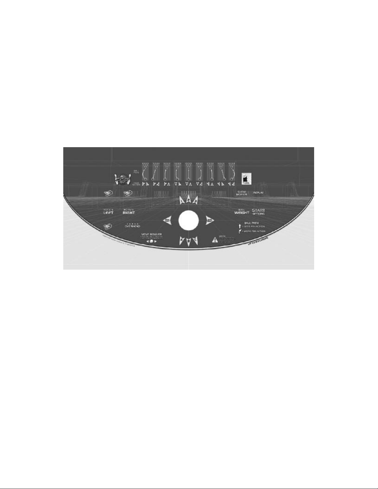
Navigating The Menus
Selecting a Menu
A menu option can be selected at any time by rolling the trackball up or down or by pressing the
Rotate Left or Rotate Right buttons.
Choosing a Menu/Option
A menu option can be chosen at any time by pressing the Start Button.
Changing a Value
A value can be changed at any time by rolling the trackball left or right.
Operator Mode Menus
The following is a listing of all the menus located in Silver Strike Bowling and their options:
Main Menu
Collections
This will reset all audits in the Game Audits menu to zero
except for Lifetime Money Total.
*NOTE: This will take you to Money Audits first.
General Settings
This area allows you to adjust operator adjustables,
perform system tests, and reset your game back to factory
settings.
Silver Strike Settings
This area allows you to adjust settings specific to Silver
Strike Bowling including the player cost schedule, game
features, and game audits.
ITNet® Settings
ITNet® is unavailable for this version of Silver Strike
Bowling.
Exit
This will exit you back into the game’s attract mode.
Value Reset (Collections and Audits Reset)
This will reset all audits in the Game Audits menu to zero
except for Lifetime Money Total.
No
This will not perform the reset and take you back to the
previous menu.
Yes
This will perform the reset and take you back to the
previous menu.
Silver Strike Bowling™ Version 08/04 Page 22
© Copyright 2004 Incredible Technologies, Inc. All Rights Reserved. Unauthorized duplication is a violation of applicable law.
All other marks are the properties of their respective owners. All rights reserved.

General Settings
Operator Adjustables
This area allows you to adjust options like volume, attract
mode sounds, skill level, and money slot settings.
System Tests
This area allows you to perform diagnostics including video
adjustments, input tests, and sound tests.
Back
This will take you back to the Main Menu.
Operator Adjustables
General Adjustments
This area allows you to adjust options like coin message,
skill level, and money modes.
Money Slot Adjustments
This area allows you to adjust the settings of your various
money slots on your cabinet.
Sound Adjustments
This area allows you to adjust the various sound settings
including attract mode sounds, game volume, and stereo
setup.
Reset To Factory Settings
This option allows you to reset all the settings found in the
Operator Adjustables section to factory defaults.
Back
This will take you back to the General Settings menu.
General Adjustments
Coin Message
If set to Insert $ it will ask the player to insert money. If set
to Swipe Card it will ask them to swipe their card to start. If
set to Insert Tokens it will ask the player to insert tokens.
The default is set to Insert $.
Skill Level
This option adjusts from 1 (Easy) to 3 (Hard). The default
is set to 2 - Normal.
Game Mode
This lets you toggle between money/free play. The default
is set to Money Play.
Reset Values
This resets all values to their default value located on this
page.
Back
This will take you back to the Operat or Adjustables menu.
Silver Strike Bowling™ Version 08/04 Page 23
© Copyright 2004 Incredible Technologies, Inc. All Rights Reserved. Unauthorized duplication is a violation of applicable law.
All other marks are the properties of their respective owners. All rights reserved.

Value Reset (General Adjustments)
This will reset Coin Message, Skill Level, & Game Mode to
their default value.
No
This will not perform the reset and take you back to the
previous menu.
Yes
This will perform the reset and take you back to the
previous menu.
Money Slot Adjustments
Money Slot 1
This adjusts how much one pulse equals for Money Slot 1.
The default is set to $0.25.
Money Slot 2
This adjusts how much one pulse equals for Money Slot 2.
The default is set to $0.25.
Money Slot 3
This adjusts how much one pulse equals for Money Slot 3.
The default is set to $0.25.
Reset Values
This resets all values to their default value located on this
page.
Back
This will take you back to the Operator Adjustables menu.
Value Reset (Money Slot Adjustments)
This will reset all Money Slots to their default value.
No
This will not perform the reset and take you back to the
previous menu.
Yes
This will perform the reset and take you back to the
previous menu.
Silver Strike Bowling™ Version 08/04 Page 24
© Copyright 2004 Incredible Technologies, Inc. All Rights Reserved. Unauthorized duplication is a violation of applicable law.
All other marks are the properties of their respective owners. All rights reserved.

Sound Adjustments
In Game Volume
This option lets you adjust the In Game volume from OFF
to 100%. The default is set to 18%.
Attract Volume
This option lets you adjust the Attract Volume from OFF to
100%. The default is set to 18%.
Attract Mode Sounds
This adjusts how often sounds are played in the attract
mode: Never, Rarely (every 10th time), Sometimes (every
5th time), Often (every other time), and Always. The
default is set to On - Sometimes.
Stereo/Mono
This option is where you select stereo or mono setup. The
default is set to Mono.
Reset Values
This resets all values to their default value located on this page.
Back
This will take you back to the Operator Adjustables menu.
Value Reset (Sound Adjustments)
This will reset the In Game Volume, Attract Volume, Attract
Mode Sounds, & Stereo/Mono settings to their default
value.
No
This will not perform the reset and take you back to the
previous menu.
Yes
This will perform the reset and take you back to the
previous menu.
Value Reset (Reset to Factory Settings)
This will reset all the settings found in the Operator
Adjustables section to their factory default value.
No
This will not perform the reset and take you back to the
previous menu.
Yes
This will perform the reset and take you back to the
previous menu.
Silver Strike Bowling™ Version 08/04 Page 25
© Copyright 2004 Incredible Technologies, Inc. All Rights Reserved. Unauthorized duplication is a violation of applicable law.
All other marks are the properties of their respective owners. All rights reserved.

System Tests
Video Tests
This area has tests that will help you to adjust your game’s
color, contrast, and screen size.
Sound Tests
This area has tests that will help you adjust your game’s
audio setup by playing a stored sound, a streaming sound,
and testing the speaker(s).
Player Control Tests
This option allows you to test all inputs including trackball,
buttons, and money slots.
Mechanical Meter Test
This test makes the hard meter adjust by one to make sure
it is functioning properly.
Hardware Tests
This area includes a series of diagnostic screens and tests to help you make sure your game is functioning
correctly.
Back
This will take you back to the General Settings menu.
Video Tests
Color Adjustments
This area will take you to a series of tests to adjust your
monitor’s RGB settings to have each color display properly.
Contrast Adjustments
This area will take you to a series of tests to adjust your
monitor’s brightness/contrast so the game displays
properly.
Screen Size Adjustment
Use this screen to align your monitor so that all the circles
appear as circles and the boundary line appears on the
edge of each side of the screen.
Back
This will take you back to the System Tests menu.
Color Adjustments
Color Grid Adjustment
Adjust your monitor to have each colored box display
properly.
Red Screen
Adjust your monitor to have red display properly.
Green Screen
Adjust your monitor to have green display properly.
Blue Screen
Adjust your monitor to have blue display properly.
Back
This will take you back to the Video Tests menu.
Silver Strike Bowling™ Version 08/04 Page 26
© Copyright 2004 Incredible Technologies, Inc. All Rights Reserved. Unauthorized duplication is a violation of applicable law.
All other marks are the properties of their respective owners. All rights reserved.

Contrast Adjustments
White Screen
Adjust your monitor to have white display properly.
50% White Screen
Adjust your monitor to have 50% white display properly.
25% White Screen
Adjust your monitor to have 25% white display properly.
Black Screen
Adjust your monitor to have black display properly.
Contrast Screen
This option is a test you can use to adjust your monitor’s
contrast and brightness settings to have the boxes
displayed properly. Note: May not work on older or often
used monitors.
If you have a monitor that's old or has been used often you may not be able to adjust the contrast and/or
brightness levels accordingly. In this case adjust the monitor for best performance while getting close to
the recommended settings.
Back
This will take you back to the Video Tests menu.
Sound Tests
Stored Sound
This will play a stored sound so you can make sure your
audio setup is functioning properly.
Streaming Sound
This will play a streaming sound so you can make sure your
audio setup is functioning properly.
Speaker Test
This test will say MONO if you have your game set to Mono
or LEFT and RIGHT if you have it set to stereo so you can
make sure your audio setup is functioning properly.
Back
This will take you back to the System Tests menu.
Mechanical Meter
Click Meter
This test makes the hard meter adjust by one to make sure
it is functioning properly.
Back
This will take you back to the System Tests menu.
Silver Strike Bowling™ Version 08/04 Page 27
© Copyright 2004 Incredible Technologies, Inc. All Rights Reserved. Unauthorized duplication is a violation of applicable law.
All other marks are the properties of their respective owners. All rights reserved.

Hardware Tests
Hardware/Software
This area has options to view your system and USB info.
Check Hard Drive
This test checks the integrity of your hard drive’s data.
Note: This test can take several minutes.
Check Cooling
This test helps you make sure your game is functioning at
the proper temperature and all fans are working.
Check Card Reader
Card functionality is not available for this version of Silver
Strike Bowling.
Back
This will take you back to the System Tests menu.
Hardware/Software
System Info
This is a list of your game’s current basic system info.
USB Info
This is a list of your game’s current USB devices.
Version Info
This is a list of your game’s software version.
Back
This will take you back to the Hardware Tests menu.
System Info
This is a list of your game’s current basic system info.
Back
The Back button takes you back to the previous menu.
Silver Strike Bowling™ Version 08/04 Page 28
© Copyright 2004 Incredible Technologies, Inc. All Rights Reserved. Unauthorized duplication is a violation of applicable law.
All other marks are the properties of their respective owners. All rights reserved.

USB Info
This is a list of your game’s current USB devices.
Back
The Back button takes you back to the previous menu.
Version Info
This is a list of your game’s software version.
Back
The Back button takes you back to the previous menu.
Check Hard Drive
Begin Test
This will initiate the test to check the integrity of your hard
drive’s data. Note: This can take several minutes.
If this test succeeds you will see the message: Status:
Hard Drive Functioning Properly. If this test fails, you will
see the message: Hard Drive Error (#)
- Please call IT Technical Support if you receive a
failure message.
Back
This will take you back to the Hardware Tests menu.
Silver Strike Bowling™ Version 08/04 Page 29
© Copyright 2004 Incredible Technologies, Inc. All Rights Reserved. Unauthorized duplication is a violation of applicable law.
All other marks are the properties of their respective owners. All rights reserved.

Check Cooling
This checks that your game is functioning at the proper
temperature and all fans are working.
Back
The Back button takes you back to the Hardware Tests
menu.
Silver Strike Settings
Player Cost Sc hedule
This option allows you to adjust the amount of money it
costs a player to play various game types.
Game Audits
This area allows you to view your money audits, game
purchase audits, and reset your collections and audits.
Game Options
This area allows you to adjust options specific to Silver
Strike Bowling including Vegas mode.
Game Event Info
This menu contains various player performance totals
including spare and strike percentages to help you adjust
your game to your local players.
Reset Leaderboards
This option will reset your game’s High Game leaderboard and 3 Game Series leaderboard in the attract mode.
Ticket Dispenser
This menu contains various options to set your game's ticket dispenser settings and clear any tickets owed.
Back
This will take you back to the Main Menu.
Silver Strike Bowling™ Version 08/04 Page 30
© Copyright 2004 Incredible Technologies, Inc. All Rights Reserved. Unauthorized duplication is a violation of applicable law.
All other marks are the properties of their respective owners. All rights reserved.

Player Cost Schedule
3 Frames
This option lets you adjust how much it costs a player to
play a three frame game and buy an additional 3 frames
after that. RECOMMENDED: 3 Frames = ½ cost of Single
Play. The default is set to $0.50.
Single Play
This option lets you adjust how much it costs a player to
play a single game. WARNING: Single Play should cost
less than Series Play. The default is set to $1.00.
Series Play
This option lets you adjust how much it costs a player to
play a series, which is three full games in a row.
WARNING: Series Play should cost more than Single
Play. The default is set to $2.50.
Reset Values
This resets all values to their default value located on this page.
Back
This will take you back to the Silver Strike Settings menu.
Value Reset (Player Cost Schedule)
This will reset the cost of 3 Frames, Single Play & Series
Play to their default value.
No
This will not perform the reset and take you back to the
previous menu.
Yes
This will perform the reset and take you back to the
previous menu.
Silver Strike Bowling™ Version 08/04 Page 31
© Copyright 2004 Incredible Technologies, Inc. All Rights Reserved. Unauthorized duplication is a violation of applicable law.
All other marks are the properties of their respective owners. All rights reserved.

Game Audits
Money Audits
This menu contains various audit totals including the
amount of money entered in to the various money slots,
money available, and lifetime money counts.
Game Purchase Audits
This menu contains totals including the number of three
frame games, Single vs Series games, and Classic vs.
Vegas games.
Ticket Dispenser Audits
This menu will allow you to view the total amount of tickets
given out and the payout percentage.
Collection & Audi ts Reset
This will reset all audits in the Game Audits menu to zero
except for Lifetime Money Total.
Back
This will take you back to the Silver Strike Settings menu.
Money Audits
Collection & Audits Reset
This will reset all audits in the Game Audits menu to zero
except for Lifetime Money Total.
Back
This will take you back to the previous menu.
Value Reset (Collections and Audits Reset)
This will reset all audits in the Game Audits menu to zero
except for Lifetime Money Total.
No
This will not perform the reset and take you back to the
previous menu.
Yes
This will perform the reset and take you back to the
previous menu.
Silver Strike Bowling™ Version 08/04 Page 32
© Copyright 2004 Incredible Technologies, Inc. All Rights Reserved. Unauthorized duplication is a violation of applicable law.
All other marks are the properties of their respective owners. All rights reserved.

Game Purchase Audits
Collection & Audits Reset
This will reset all audits in the Game Audits menu to zero
except for Lifetime Money Total.
Back
This will take you back to the Game Audits menu.
Value Reset (Collections and Audits Reset)
This will reset all audits in the Game Audits menu to zero
except for Lifetime Money Total.
No
This will not perf orm the reset and take you back to the
previous menu.
Yes
This will perform the reset and take you back to the
previous menu.
Ticket Dispenser Audits
Collection & Audits Reset
This will reset all audits in the Game Audits menu to zero
except for Lifetime Money Total.
Back
This will take you back to the Game Audits menu.
Silver Strike Bowling™ Version 08/04 Page 33
© Copyright 2004 Incredible Technologies, Inc. All Rights Reserved. Unauthorized duplication is a violation of applicable law.
All other marks are the properties of their respective owners. All rights reserved.

Value Reset (Collections and Audits Reset)
This will reset all audits in the Game Audits menu to zero
except for Lifetime Money Total.
No
This will not perform the res et and take you back to the
previous menu.
Yes
This will perform the reset and take you back to the
previous menu.
Value Reset (Collections and Audits Reset)
--Located off the main Game Audits menu. Same as the above Collections and Audits Reset menus.
Game Options
Vegas Bowling
This option lets you turn the Vegas bowling feature On or
Off. The default is set to On.
Delay Timeout
Based on this time setting, ranging from OFF to 2 minutes,
the player receives a warning to take their turn. The default
is set to 0:25 seconds. Note: The timeout on the first
frame is always 2 minutes.
Ball Timeout
This option lets you choose how many balls, if any, the
game will allow the player to miss before exiting them out of
the game. Note: This only work s if your Delay Timeout is
not set to Off. The default is set to 4 Balls.
Reset Values
This resets all values to their default value located on this page.
Back
This will take you back to the Silver Strike Settings menu.
Silver Strike Bowling™ Version 08/04 Page 34
© Copyright 2004 Incredible Technologies, Inc. All Rights Reserved. Unauthorized duplication is a violation of applicable law.
All other marks are the properties of their respective owners. All rights reserved.

Value Reset (Game Options)
This will reset Vegas Bowling, Delay Timeout, & Ball
Timeout to their default value.
No
This will not perform the reset and take you back to the
previous menu.
Yes
This will perform the reset and take you back to the
previous menu.
Game Event Info
Reset Game Events
This will reset all values shown on this page to zero.
Back
This will take you back to the Silver Strike Settings menu.
Value Reset (Game Event Info)
This will reset Game Event Info values to zero.
No
This will not perform the reset and take you back to the
previous menu.
Yes
This will perform the reset and take you back to the
previous menu.
Silver Strike Bowling™ Version 08/04 Page 35
© Copyright 2004 Incredible Technologies, Inc. All Rights Reserved. Unauthorized duplication is a violation of applicable law.
All other marks are the properties of their respective owners. All rights reserved.

Value Reset (Reset Leaderboards)
This will clear the High Game leaderboard & 3 Game
Series leaderboard.
No
This will not perf orm the reset and take you back to the
previous menu.
Yes
This will perform the reset and take you back to the
previous menu.
Ticket Dispenser
Dispenser Settings
This menu allows you to adjust whether your ticket
dispenser is On/Off, how many tickets are dispensed per
completed game, and the monetary value of a ticket.
Ticket Settings
This menu allows you to adjust how many tickets are
dispensed for various game options including strikes,
spares, and various "hands" in Vegas bowling.
Clear Tickets Owed
This menu will allow you to see how many tickets were not
dispensed and owed to players and let you clear them.
Back
This will take you back to the Silver Strike Settings menu.
Dispenser Settings
Ticket Dispenser
This option allows you to adjust ticket dispenser
functionality to On or Off.
Tickets per Game Completed
This option allows you to adjust how many tickets will be
dispensed to the player for completing one game.
Value of One Ticket
This option allows you to adjust the monetary value of one
ticket.
Test Dispense One Ticket
This option will have the ticket dispenser send one ticket
through for test.
Reset Values
This option will reset all values located on this page to their default values.
Back
This will take you back to the Ticket Dispenser menu.
Silver Strike Bowling™ Version 08/04 Page 36
© Copyright 2004 Incredible Technologies, Inc. All Rights Reserved. Unauthorized duplication is a violation of applicable law.
All other marks are the properties of their respective owners. All rights reserved.

Value Reset (Dispenser Settings)
This will reset all Dispenser Settings to their default values.
No
This will not perform the reset and take you back to the
previous menu.
Yes
This will perform the reset and take you back to the
previous menu.
Ticket Settings
Ticket(s) per _ Strike(s)
This adjusts the number of tickets that are dispensed per
certain number of strikes by rolling the trackball left or right.
Ticket(s) per _ Spare(s)
This adjusts the number of tickets that are dispensed per
certain number of spares by rolling the trackball left or right.
Ticket(s) per Royal Flush
This option lets you adjust how many tickets are dispensed
for a Royal Flush in Vegas Bowling.
Ticket(s) per Straight Flush
This option lets you adjust how many tickets are dispensed
for a Straight Flush in Vegas Bowling.
Ticket(s) per 4 of a Kind
This option lets you adjust how many tickets are dispensed for a 4 of a Kind in Vegas Bowling.
Ticket(s) per Full House
This option lets you adjust how many tickets are dispensed for a Full House in Vegas Bowling.
Ticket(s) per Flush
This option lets you adjust how many tickets are dispensed for a Flush in Vegas Bowling.
Ticket(s) per Straight
This option lets you adjust how many tickets are dispensed for a Straight in Vegas Bowling.
Ticket(s) per 3 of a Kind
This option lets you adjust how many tickets are dispensed for a 3 of a Kind in Vegas Bowling.
Reset Values
This option will reset all values located on this page to their default values.
Back
This will take you back to the Ticket Dispenser menu.
Silver Strike Bowling™ Version 08/04 Page 37
© Copyright 2004 Incredible Technologies, Inc. All Rights Reserved. Unauthorized duplication is a violation of applicable law.
All other marks are the properties of their respective owners. All rights reserved.

Value Reset (Ticket Settings)
This will reset all Ticket Settings to their default values.
No
This will not perform the reset and take you back to the
previous menu.
Yes
This will perform the reset and take you back to the
previous menu.
Clear Tickets Owed
Clear Tickets
This will reset the number of tickets owed to players to
zero.
Back
This will take you back to the Ticket Dispenser menu.
Value Reset (Clear Tickets Owed)
This will clear the tickets owed.
No
This will not perform the reset and take you back to the
previous menu.
Yes
This will perform the reset and take you back to the
previous menu.
Silver Strike Bowling™ Version 08/04 Page 38
© Copyright 2004 Incredible Technologies, Inc. All Rights Reserved. Unauthorized duplication is a violation of applicable law.
All other marks are the properties of their respective owners. All rights reserved.

Silver Strike Bowling
Troubleshooting
And Reference
Silver Strike Bowling™ Version 08/04 Page 39
© Copyright 2004 Incredible Technologies, Inc. All Rights Reserved. Unauthorized duplication is a violation of applicable law.
All other marks are the properties of their respective owners. All rights reserved.

APPENDIX A
Troubleshooting Index
Video Problems
Symptom Probable Cause Solution
No picture
No picture but game sounds are
heard
Scrambled Picture
Entire picture is not seen on the
screen or it does not fill the entire
screen
Missing or washed out colors
I/O Board Dip Switch settings are
wrong.
Incorrect video connection
configuration.
Monitor does not have a proper
A.C. voltage input.
Monitor is defective. Repair or replace.
Defective I/O board. Applies only to
systems utilizing video scaling on
the I/O board. For Low and
Medium Resolution monitors.
Check for Flash Code 1 on lighted
diode D102 of the I/O board.
Nighthawk Chassis is defective Go to Nighthawk Chassis
Incorrect video connection
configuration.
Since you hear game sounds the
system is working.
I/O board Dip Switch settings are
set wrong.
Misadjusted monitor. Analog
monitor mid. and low resolution.
Most digital monitors sync
automatically.
Incorrect video connection
configuration.
Misadjusted monitor. Adjust the monitor width and height.
Bad Video connections Verify continuity from the monitor to
Contrast and brightness on the
monitor needs to be adjusted.
Defective Monitor. Verify by connecting a known good
Adjust Dip Switch settings to match
the resolution of the monitor you are
using. Refer to Dip Switch Settings
on page 15.
Be sure the video connections are
correct according to the type of
monitor you are using. Refer to
cable connection diagram - page 45.
Verify A.C. power to the Nighthawk
Chassis. Verify monitor is working
on a known good system.
Repair or replace.
Plug in the USB connection to the
I/O board to the USB. Video should
appear if scaling is used.
troubleshooting section.
Verify video is connected to the
system correctly. Refer to cable
connection diagram - page 45.
Review no picture troubleshooting
section above.
Adjust Dip Switch settings to match
the resolution of the monitor you are
using. Refer to Dip Switch Settings
on page 15.
Adjust the horizontal and vertical
sync on the monitor. Refer to the
monitor manual.
Be sure the video connections are
correct according to the type of
monitor you are using. Refer to
cable connection diagram - page 45.
Use video screen adjustment in
system tests. Refer to the monitor
manual.
the video out on the I/O board. Red,
Green, Blue video signal. Mid. and
Low resolution monitors only.
Refer to the monitor manual to make
adjustments.
monitor to the system.
Silver Strike Bowling™ Version 08/04 Page 40
© Copyright 2004 Incredible Technologies, Inc. All Rights Reserved. Unauthorized duplication is a violation of applicable law.
All other marks are the properties of their respective owners. All rights reserved.

Sound Problems
Symptom Probable Cause Solution
No Sound
Audio Cable between the I/O board
and the Nighthawk Chassis are not
Verify audio cables are connected.
See diagram on page 45.
connected.
Speakers are not connected
properly.
Verify continuity from the I/O board
speaker output pins to the speakers.
Refer to pin out diagram - page 43.
Volume is set to the lowest level. Adjust the volume to an audible
level.
Attract mode sounds may be set to
all off. You will have sounds when
playing the game.
Choose one of the 5 Attract Mode
sound options in Sound
Adjustments.
Defective Nighthawk Chassis. Be certain all other possibilities are
explored before replacing the
Nighthawk Chassis.
Distorted or scratchy game sounds
Bad speaker. Replace blown speaker.
Loose speaker or grill cover is
causing vibration.
Loose/defective audio cables from
the Nighthawk Chassis to the I/O
Verify all components are installed
properly and securely.
Check the audio cable connections.
Replace cable.
board.
Defective I/O board. Verify on a known working system.
Replace if necessary.
Control Problems
Symptom Probable Cause Solution
Button does not work.
Button always indicates closed in
the player control test. Pressing it
will show it is not depressed.
Button always indicates closed in
player control test even with the
switch disconnected entirely.
Trackball is not functioning in any
direction.
Trackball does not work in a
certain direction.
Trackball works intermittently.
Switches Common post is not
connected to digital ground.
Signal wire is not connected to the
Normally Open post of the switch.
Switch is defective. Replace defective switch.
Signal wire is connected to the
Normally Closed post of the switch.
Defective I/O board. Test on a known good system.
Trackball is not connected to the
I/O board properly.
Defective trackball Interconnect
cable.
Trackball is defective. Replace trackball.
I/O board is defective Replace I/O board. Try it on a
Trackball cable is defective. Verify continuity on the trackball
Trackball is defective. Repair or replace the trackball. Try it
I/O board is defective. Repair or replace the I/O board. Try
Inside of the trackball is dirty. Clean the inside of the trackball.
Rollers are worn. Replace the rollers and bearings.
Trackball is over -tightened. Do not over-tighten the trackball.
Verify continuity to digital/power
supply ground.
Verify continuity from the I/O board
to the Normally Open post of the
switch.
Connect signal wire to the Normally
Open post of the switch.
Replace if necessary.
Verify the trackball is connected to
J208 labeled trackball on the I/O
board.
Verify continuity on the trackball
Interconnect cable.
known good system.
cable. Repair or replace if needed.
on a known working system.
it on a known working system.
Tighten just enough to flatten the
lock washers.
Silver Strike Bowling™ Version 08/04 Page 41
© Copyright 2004 Incredible Technologies, Inc. All Rights Reserved. Unauthorized duplication is a violation of applicable law.
All other marks are the properties of their respective owners. All rights reserved.

Nighthawk Chassis Problems
Symptom Probable Cause Solution
No video and no green lights on
the I/O board. Fans are not heard
on the Nighthawk Chassis.
No A.C. power to the Nighthawk
Chassis.
Power switch on the Nighthawk
Chassis is off.
Verify A.C. voltage is connected to
the Nighthawk Chassis.
Flip the Nightha wk Chassis power
switch to on.
Main cabinet power switch is off. Be certain the main cabinet switch is
set to on.
Defective Nighthawk Chassis. Be certain all other possibilities are
explored before replacing the
Nighthawk Chassis.
No video and no green lights on
the I/O board. Fans are heard on
the Nighthawk Chassis.
DC power cord not connected from
Nighthawk Chassis to I/O board.
Defective I/O board. Try it on a known good system.
Connect the DC power cord from the
Nighthawk Chassis to the I/O board.
Verify by disconnecting all cables
from the I/O board except the DC
power and USB cable to the
Nighthawk Chassis. No green lights,
replace the I/O board.
Error Messages
Symptom Probable Cause Solution
Most on screen error messages
explain themselves .
Multiple Follow the onscreen instructions.
Many times turning the game off for
ten seconds and then turning it back
on will solve the error.
Flash code 6 on I/O board Diode
D102
CID is not connected or is
defective
Check the USB cable connection.
Swap with a known good cable. Call
I.T. Service for further assistance.
Please turn game off, then connect
Cabinet Identification Device (CID)
then turn game back on.
CID is not connected Connect CID to the Nighthawk
Chassis via USB cable.
CID cable is defective Try or swap with a known good USB
cable.
Flash code 1 on I/O board diode
D102
Please turn game off, Then
connect USB I/O board and then
turn game back on.
If LED is not flashing - Call I.T.
Service
This indicates to USB connection
fail from Chassis to I/O board.
USB cable is not connected Connect the USB cable.
USB cable is Defective Try with a known good USB cable.
I/O board has no power
I.T. service will instruct you what to
do.
Connect USB Cable.
Verify power to the I/O board.
connection.
I/O board is defective Swap with a known good I/O board.
Possibly bad. Cal I.T. service.
Miscellaneous Problems
Symptom Probable Cause Solution
Unable to exit Operator Menus.
Dipswitch SW202 position 4 is in
the on position.
Test switch wired from the I/O
board is closed.
No fluorescent light
No 120 volts A.C. power going to
the light fixture.
Defective fluorescent light. Replace fluorescent light.
Defective starter Replace the starter.
Defective ballast. Replace the ballast.
Coin Meter is not working Defective Coin Meter Replace with a known good one.
Not wired properly Connect one lead to +5 or +12 volts
Defective I/O board Replace with a known good board.
Silver Strike Bowling™ Version 08/04 Page 42
© Copyright 2004 Incredible Technologies, Inc. All Rights Reserved. Unauthorized duplication is a violation of applicable law.
All other marks are the properties of their respective owners. All rights reserved.
Set position 4 of SW202 to off.
Press start to exit.
Verify satellite test switch is not
closed.
Verify A.C. voltage to the light
fixture.
depending on device. The other lead
to count 1 on the JAMMA connector.

APPENDIX B
JAMMA, Trackball, and I/O Power Connection
JAMMA Harness Connection
SOLDER SIDE PARTS SIDE
WIRE COLOR FUNCTION FUNCTION WIRE COLOR
Black * A 1 * Black
Black * B 2 * Black
Red * C 3 * Red
Red * D 4 * Red
E 5
Orange * F 6 * Orange
KEY H 7 KEY
Count 2 J 8 Coin Counter Red-Green
K 9
Yellow-Green Left Speaker (-) L 10 Left Speaker (+) Yellow -Red
White-Green Right Speaker (-) M 11 Right Speaker (+) White-Red
Green-Black Video Green N 12 Video Red Red-Black
White Video Sync P 13 Video Blue Blue-Black
R 14 Video GND White-Black
S 15 Test Blue
Green-Blue Coin 2 T 16 Coin1 Red-Blue
U 17 Start 1 Red-White
V 18
W 19
X 20 Player 1 – Ball Weight Purple-White
Y 21 Player 1 – Overhead Violet-White
Z 22 Player 1 – Left Brown-White
A 23 Player 1 – Right Yellow-White
Orange-Yellow Volume Down B 24 Volume Up Orange-White
C 25 Coin 3 (Bill) Gray-White
D 26
Black GND E 27 GND Black
Black GND F 28 GND Black
*NOTE: Power is NOT routed through the JAMMA connector.
Trackball Harness Connection I/O Power Cable Pin Out Diagram
I/O Board Connector Trackball Connector Pin Number Wire Color Function
PIN WIRE #6 - Black PIN WIRE #1 – Black 1 Yellow + 12 Volts DC
PIN WIRE #1 - Red
PIN WIRE #2 - Yellow
PIN WIRE #3 - Green
PIN WIRE #5 - Blue
PIN WIRE #2 – Red 2 Black Ground
PIN WIRE #3 – Yellow
3 Red + 5 Volts DC
PIN WIRE #4 – Green 4 Black Ground
PIN WIRE #5 – Blue
PIN WIRE #4 - Purple PIN WIRE #6 – Purple
Silver Strike Bowling™ Version 08/04 Page 43
© Copyright 2004 Incredible Technologies, Inc. All Rights Reserved. Unauthorized duplication is a violation of applicable law.
All other marks are the properties of their respective owners. All rights reserved.

Nighthawk Chassis and I/O Board Diagrams
Nighthawk Chassis Diagram
Kit I/O Board Diagram
Dedicated I/O Board Diagram
Silver Strike Bowling™ Version 08/04 Page 44
© Copyright 2004 Incredible Technologies, Inc. All Rights Reserved. Unauthorized duplication is a violation of applicable law.
All other marks are the properties of their respective owners. All rights reserved.

Detailed Cable Connection Diagram
Silver Strike Bowling™ Version 08/04 Page 45
© Copyright 2004 Incredible Technologies, Inc. All Rights Reserved. Unauthorized duplication is a violation of applicable law.
All other marks are the properties of their respective owners. All rights reserved.

SSB Cabinet Wiring Diagram
Silver Strike Bowling™ Version 08/04 Page 46
© Copyright 2004 Incredible Technologies, Inc. All Rights Reserved. Unauthorized duplication is a violation of applicable law.
All other marks are the properties of their respective owners. All rights reserved.

APPENDIX C
Game Icon Descriptions
Cooling Icon
The cooling icon (pictured right) will appear in the game's attract mode to warn you
that a fan is not operating at minimum recommended standards. If the fans do not perate at suggested levels it may cause your game to overheat and fail. Call
Incredible Technologies Technical Support at 847-870-7027 x121 for assistance.
NOTE: Opening the Nighthawk Chassis system
will void your warranty!
Tickets Owed Icon
The tickets owed icon (pictured right) will appear in the game's attract mode to warn
you that the ticket dispenser is not dispensing tickets. It then tells you how many
tickets are owed to players.
Trackball and Button Templates
Trackball Template and Orientation Diagram
Included in this appendix are two templates for you to use when preparing your control panel for trackball
installation into the control panel. The first is an installation template you can copy and use right on your control
panel to make the necessary routing and holes required to install the trackball plate. Included on this "actual size"
template are instructions for use of the template. The second is a diagram that shows the proper orientation when
installing the trackball to the trackball plate. The orientation of the trackball is very important for correct wiring and
game play. These templates can be found on page 49 and 51.
Button Template and Orientation
Included in this appendix are two templates you can use to help space and orient the two sets of buttons on your
control panel. This will allow you to properly drill the holes for the buttons into your control panel and keep them
spaced at proper distances from the trackball. These templates can be found on page 53.
For guidance on the layout please refer to the diagram below:
Silver Strike Bowling™ Version 08/04 Page 47
© Copyright 2004 Incredible Technologies, Inc. All Rights Reserved. Unauthorized duplication is a violation of applicable law.
All other marks are the properties of their respective owners. All rights reserved.

Silver Strike Bowling™ Version 08/04 Page 48
© Copyright 2004 Incredible Technologies, Inc. All Rights Reserved. Unauthorized duplication is a violation of applicable law.
All other marks are the properties of their respective owners. All rights reserved.

Silver Strike Bowling™ Version 08/04 Page 49
© Copyright 2004 Incredible Technologies, Inc. All Rights Reserved. Unauthorized duplication is a violation of applicable law.
All other marks are the properties of their respective owners. All rights reserved.

Silver Strike Bowling™ Version 08/04 Page 50
© Copyright 2004 Incredible Technologies, Inc. All Rights Reserved. Unauthorized duplication is a violation of applicable law.
All other marks are the properties of their respective owners. All rights reserved.

Silver Strike Bowling™ Version 08/04 Page 51
© Copyright 2004 Incredible Technologies, Inc. All Rights Reserved. Unauthorized duplication is a violation of applicable law.
All other marks are the properties of their respective owners. All rights reserved.

Silver Strike Bowling™ Version 08/04 Page 52
© Copyright 2004 Incredible Technologies, Inc. All Rights Reserved. Unauthorized duplication is a violation of applicable law.
All other marks are the properties of their respective owners. All rights reserved.

Silver Strike Bowling™ Version 08/04 Page 53
© Copyright 2004 Incredible Technologies, Inc. All Rights Reserved. Unauthorized duplication is a violation of applicable law.
All other marks are the properties of their respective owners. All rights reserved.

Silver Strike Bowling™ Version 08/04 Page 54
© Copyright 2004 Incredible Technologies, Inc. All Rights Reserved. Unauthorized duplication is a violation of applicable law.
All other marks are the properties of their respective owners. All rights reserved.

APPENDIX D
Replacement Part Numbers
Please refer to these IT part numbers when placing orders.
Silver Strike Bowling Dedicated (Part # 925000265D) an d Silver Strike Bowling Kit (Part# 925000265):
Quantity Part Description Part Number Dedicated/Kit
1 Silver Strike Bowling Cabinet 960000265 Dedicated Only
1 Nighthawk Chassis (System Box) 900000265 Both
1 Silver Strike Bowling Marquee 820000265 Both
1 Silver Strike Bowling Set of Side Decals 830000265 Both
1 Silver Strike Bowling Control Panel Background 825100265 Kit Only
1 IT Logo Card 840000000 Dedicated Only
1 Screened Control Panel 845000265 Dedicated Only
1 Adhesive Square (For Control Panel) 840000845 Dedicated Only
1 3" White Trackball Assembly 880000030 Both
1 Trackball Plate for Trackball Assembly 885000030 Both
1 Cabinet Identification Device (C.I.D.) Assembly 900174001 Both
1 Kit I/O Board Assembly 900000017 Kit Only
1 Dedicated I/O Board Assembly 900900017 Dedicated Only
1 I/O Board Power Cable 915000275 Both
1 6 Ft. Audio Cable 915000285 Both
1 6 Ft. Male/Male SVGA Cable 915000315 Kit Only
1 3 Ft. Male/Male SVGA Cable 915000085 Dedicated Only
3 6 Ft. USB Cables 915000310 Both
1 AC Power Cord 915000745 Both
1 Bag of Parts for Assembly 900265030 Kit Only
1 Silver Strike Bowling Manual 815000265 Both
1 Quick Install Guide 840000265 Kit Only
1 Monitor Safety Glass 999000150 Dedicated Only
1 Monitor Bezel 999000027 Dedicated Only
1 Security Bar Kit 795000187 Dedicated Only
1 Blue Side Wing - Left 999000045L Dedicated Only
1 Blue Side Wing - Right 999000045R Dedicated Only
1 Plexiglas® For IT Logo Card C301-512-000 Dedicated Only
1 Speaker Grille C301-025-OPA Dedicated Only
2 Speakers A056-015-000 Dedicated Only
2 Monitor Mounting Bracket C301-100-1PA Dedicated Only
4 Leg Leveler Plate 999000110 Dedicated Only
4 Leg Leveler With Stop Nut 999000120 Dedicated Only
1 Scruff Strip For Cabinet C301-511-000 Dedicated Only
1 Bracket, Shelf Trim With Foam For Cabinet 999000090 Dedicated Only
2 Marquee Retainer 999000040 Dedicated Only
1 Control Panel Cable C304-060-000 Dedicated Only
1 Coin Door Cable C304-061-000 Dedicated Only
1 Speaker Cable C304-062-000 Dedicated Only
1 Speaker Panel Cable (Stereo) C304-063-000 Dedicated Only
For the following parts please call the vendor listed:
Quantity Part Description Part Number Vendor
1 Mars DBA (1/5 w/500 bill stacker) AE2451-D-5E MARS
1 Door Assembly 40-0038-39 HAPP
1 NeoTec Monitor NT-500DXB7P NeoTec
1 NeoTec Chassis Board Assembly B700DX002 NeoTec
1 Wells Monitor WGM2792-UOTS09B Wells
1 Wells Chassis Board Assembly SO7B2792-S09B Wells
1 Fluorescent Fixture (Includes Ballast And Starter) ST115X40 HAPP
1 Bulb F15T8CW HAPP
Silver Strike Bowling™ Version 08/04 Page 55
© Copyright 2004 Incredible Technologies, Inc. All Rights Reserved. Unauthorized duplication is a violation of applicable law.
All other marks are the properties of their respective owners. All rights reserved.

Contact Information
IT Sales and Service
To purchase additional Silver Strike Bowling games or any of IT's other fine products
please visit IT's website at www.itsgames.com and click on PRODUCTS!
General Numbers
Technical Support, Warranty, & Repair: Parts, Customer Service, & Operator Services:
Incredible Technologies, Inc. Incredible Technologies, Inc.
847-870-7027 x 121 847-870-7027 x 118
IT Mailing Address:
Incredible Technologies, Inc.
3333 North Kennicott Avenue
Arlington Heights, IL 60004-0129
IT Fax Number
847-870-0120
IT Vendor Information
Wells-Gardner: Mars Technical Service:
Phone: 800 -336-6630 Phone: 800-345-8172
Fax: 773-252-8299
NeoTec Happ Controls:
Phone: 909 -626-9889 Phone: 800-BUY-HAPP
Fax: 909-626-0990 (800-289 -4277)
In our replacement part numbers section is a list of parts you can get from these vendors
including the vendor's part numbers.
SILVER STRIKE BOWLING™, ITS®, INCREDIBLE TECHNOLOGIES®, IT®, ITNet®, and IT incredible TECHNOLOGIES® are the properties of
© Copyright 2004 Incredible Technologies, Inc. All Rights Reserved. Unauthorized duplication is a violation of applicable law.
All other marks are the properties of their respective owners. All rights reserved.
Incredible Technologies, Inc. All Rights Reserved.

Incredible Technologies, Inc.
3333 N. Kennicott Ave.
Arlington Heights, IL 60004
Phone (847) 870-7027 Fax (847) 870-0120
www.itsgames.com
SILVER STRIKE BOWLING™, ITS®, INCREDIBLE TECHNOLOGIES®, IT®, ITNet®, and IT incredible TECHNOLOGIES® are the properties of
© Copyright 2004 Incredible Technologies, Inc. All Rights Reserved. Unauthorized duplication is a violation of applicable law.
All other marks are the properties of their respective owners. All rights reserved.
Incredible Technologies, Inc. All Rights Reserved.
 Loading...