

Night Guard Home Surveillance System RS-725LCD User Manual
THIS PRODUCT IS DESIGNED FOR PROFESIONAL INSTALLATION ONLY
RS-725LCD
PROFESSIONAL REMOTE CAR STARTER
WITH ALARM SYSTEM
&
2-WAY LCD COMMUNICATION
OPERATION MANUAL
1

TABLE OF CONTENTS:
A BATTERY REPLACEMENT
B THE REMOTE LCD ICONS WITH FUNCTION
C PROGRAMMING OF THE LCD REMOTE TRANSMITTER
1. Screen Lamp ON
2. Power Save Mode
3. Clear The Flash Icon and Melody Sound
4. Stop The Melody Sound.
5. Button Lock
6. Vibration / Melody Mode
7. Enable / Disable Bi Sound While Pressing Button:
8. Low Battery Indication.
9. Set Up Fixed Count Down Timer
10. Out Of The Range Check
D CLOCK & TIMER SETTING
1. Clock Setting.
2. Alert Alarm Timer Setting
3. Count Down Timer Setting
4. Time Set-Up For “Daily Timer Start”
REMOTE TRANSMITTER OPERATION
A. REMOTE TRANSMITTER OPERATION
B LCD DISPLAY TRANSMITTER OPERATION
C LED DISPLAY
D CHIRP INDICATOR
E PARKING LIGHT
F ALARM OPERATION CONDITION
G ACTIVE ARMING – ARM & LOCK
Defective Sensor Reminder
Silent Arming / Disarming
Shock Sensor By-Pass
Hidden Alarm Function
H PASSIVE ARMING
Passive Arming with Passive Door Locking
Passive Arming By-Pass
I ACTIVE DISARMING – UNLOCK & DISARM
Tamper Disarming
Pathway Illumination
Two Steps Door Unlock
Automatic Re-Arm
J DISARMING WITHOUT A TRANSMITTER
Overrides the Alarm without Password Pin Code
Overrides the Alarm With Password Pin Code
K VALET MODE
Enter Valet Mode
Exit Valet Mode
L CAR LOCATOR
M PANIC FUNCTION
N TRIGGER THE SYSTEM
Clear The Trigger Icons and Melody Sound
Stop The Melody Sound Only
LCD REMOTE TRANSMITTER:
5
6
7
7
7
7
7
8
8
8
8
8
9
9
9
10
10
10
11
11
11
11
11
12
12
12
12
12
12
12
12
13
13
13
13
13
13
13
14
14
14
14
14
14
15
15
15
2

Noise Abatement Circuit
O ANTI CAR- JACKING
Active Anti Car Jacking
Passive Anti Car Jacking
Trigger The Anti Car Jacking Mode
Override The System To Turn Off Anti Car Jacking
P SYSTEM’S TRIGGER CHECK
Q SYSTEM’S STATUS CHECK
R DRIVER PAGING (OPTION)
S DOME LIGHT CONVENIENCE DELAY & SUPERVISION
T IGNITION CONTROL THE DOOR LOCK/UNLOCK
U TRUNK RELEASE (CHANNEL 3) OUTPUT
V CHANNEL 4 TIMER CONTROL OUTPUT
W POWER ON MEMORY
X SECOND VEHICLE SECURITY SYSTEM OPERATION
Programming 2nd car transmitter
For Standard Remote Transmitter
For 2-Way LCD Display Transmitter
REMOTE START OPERATION:
A TO REMOTE START THE VEHICLE
Safe Start (Child safety mode)
B TO OPERATE VEHICLE WHILE RUNNING ON REMOTE START
C TEMPORARY STOP FEATURE
D TURBO CHARGE MODE
E TIMER / TEMPERATURE START
3 (2) Hours Timer Start With Temperature-Control Off
3 (2) Hours Timer Start With Temperature-Control
Daily Timer Start
Exit the Timer Start
F TEMPERATURE CHECK
G TO TURN OFF THE REMOTE START
H SHUT-DOWN INPUT FOR REMOTE STARTER
I DISABLING THE REMOTE START SYSTEM
Congratulations on your purchase of the RS725LCD remote start vehicle security
system. We sincerely hope the purchase of the RS725 remote start security system
gives peace of mind to you.
The RS725 LCD is a state-of-the-art two-way communication system. Please take the
time to read over this manual to thoroughly familiarize your self with the many features
and options of the RS725.
Auto Page, Inc. has over 25 years of experience in the vehicle security industry in the
United States and is a wholly owned subsidiary of Iwata Electric Co., of Tokyo, Japan.
Iwata has been an industry leader for over 50 years, establishing a reputation for
ingenuity in its engineering capability and innovative communication products. Auto
Page and Iwata maintain a long tradition of providing the best value to their customers.
15
16
16
16
16
16
16
16
16
17
17
17
17
18
18
18
18
18
19
19
19
19
20
20
20
20
20
21
21
21
21
3
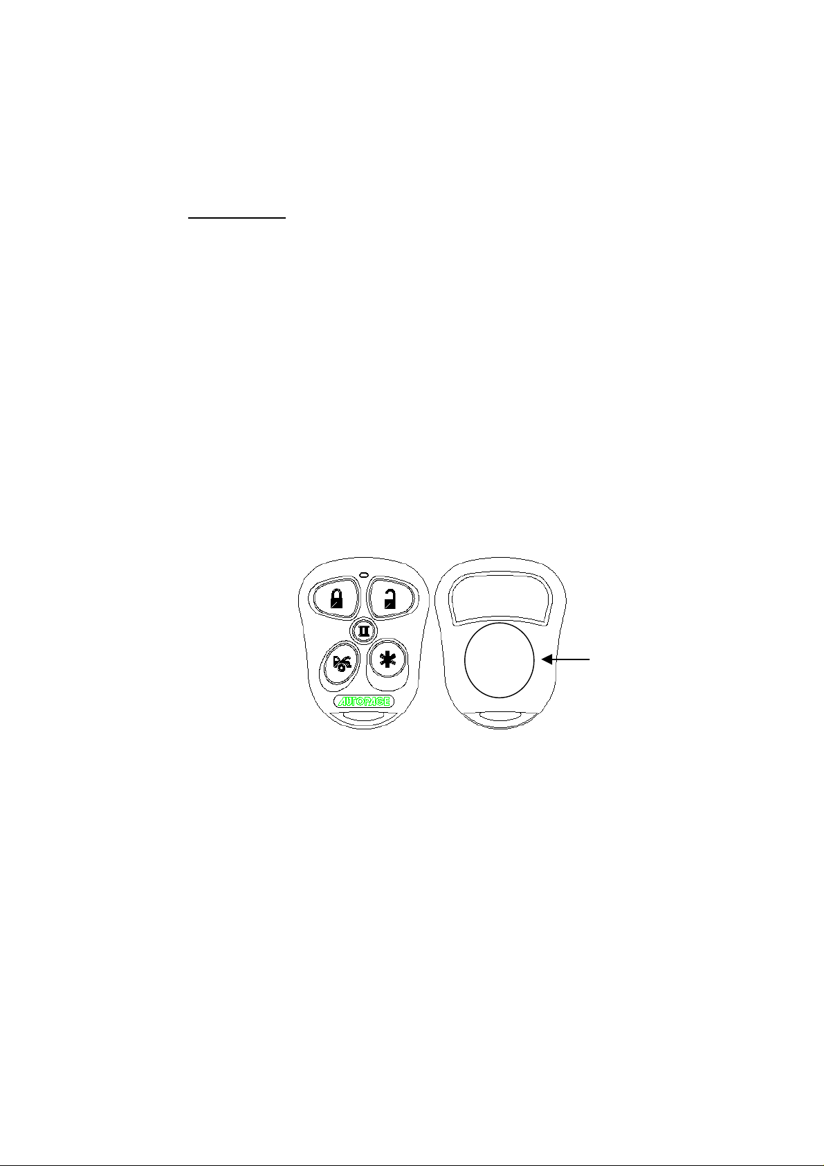
TRANSMITTERS
The RS725 comes with two transmitters. The XT72LCD is a 2-way transmitter and
receiver, also referred to as a transceiver. The XT-33 is a mini-size 1-way transmitter.
Both operate on the AM band with a code-rolling feature that will prevent any illegal use
of a code-grabber attempting to record and steal the codes of your transmitter.
CHANGING THE BATTERY IN YOUR TRANSMITTERS
XT72LCD: This transmitter uses a standard 1.5-volt AAA battery. Information on
changing the battery can be found on page 12 of this manual.
XT-33: This transmitter uses two (2) 3-volt lithium ion batteries (#CR2016) that are
sandwiched together with the (+) side facing upward. To replace the battery, you will
need to use a small flat blade screwdriver. Locate the small notch on the lower right
side of the transmitter case next to the key ring. Using the flat blade screwdriver,
carefully pry the top case from the bottom case. It should snap apart after breaking the
seal. Before removing the batteries note the direction of the positive (+) terminal.
Place the new batteries in exactly the same manner, being careful not to bend or
damage the contact terminal. Snap the cases back together and then test the
transmitter to insure it arms and disarms the alarm.
XT-33
(2) CR2016
3-Volt Batteries
4
WARNINGS:
As with any product that performs automatic functions, there are certain safety
precautions that you must practice and be aware of.
1. Keep the transmitter out of children’s reach.
2. Do not leave anyone in the vehicle while running on remote control.
3. Alert servicing personnel that the vehicle can be started automatically.
4. Do not start the vehicle by remote while it’s in an enclosed area or garage.
5. Always apply the parking brake and lock the vehicle as you exit the vehicle.
6. The vehicle windows must be rolled up.
7. Should the unit malfunction, disconnect the fuse until the problem is corrected.
8. The use and operations of this system is the sole responsibility of the operator.
9. Some areas may have local ordinances that prohibit leaving a vehicle running on
public streets.
10.Do not start the vehicle by remote while the standard transmission vehicle is parked
at a steep place.
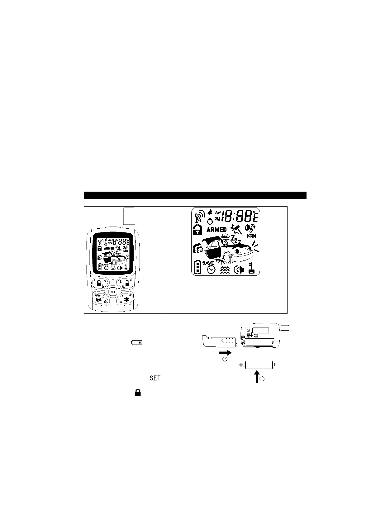
LCD REMOTE CONTROL TRANSMITTER:
Note: If the system is interfered by stronger radio
frequency around, sources of high voltage electric
power or such Obstacles like tall buildings and so
on, the transmission range may get shorter as the
system uses low out put powered frequency.
A. BATTERY REPLACEMENT:
A 1.5V type AAA Alkaline battery powers the
Remote Transmitter. When the power of the
battery weakens a icon shall be
displayed on the LCD screen. When the old
battery is replaced to new one, there will be
beep sounds indicate the power is up and
the clock on the LCD screen returns to
AM12:00 after displaying all the icons.
Correct the time by pressing for 3
seconds before using (See Timer Setting).
Note : Press the button two times when the battery compartment is
empty, then insert the new battery
5
unlocked and the system is
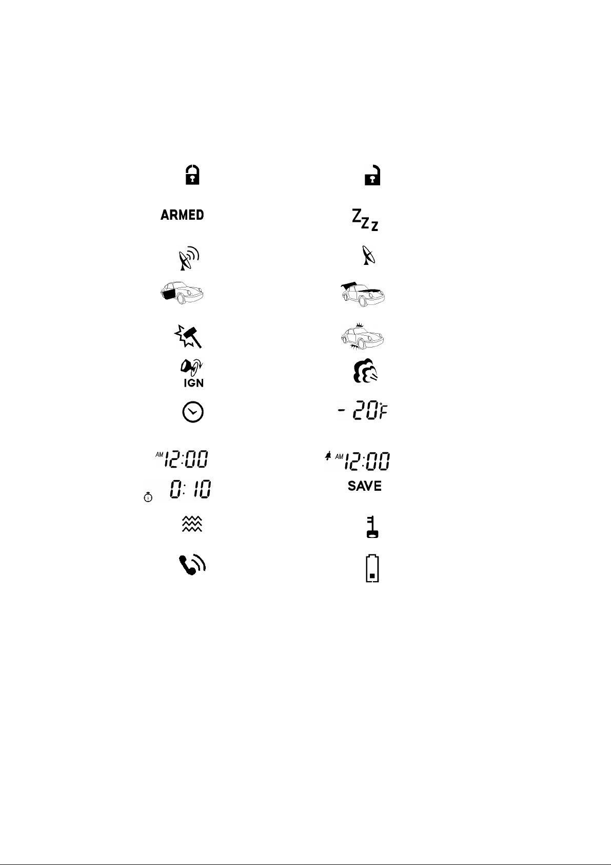
B. THE REMOTE LCD ICONS WITH FUNCTION:
Door Lock
Your vehicle doors are
locked
Armed Mode
Your vehicle is in armed
mode
Remote Transmission
You are transmitting the
signal to control unit
Door Open Warning
Doors are illegally opened
(Zone 3)
Door Unlock
Your vehicle doors are
Disarmed
Valet Mode
All the function shall be
temporarily on hold.
In – Range Indicator
Your are within range of
the remote control
Trunk/Hood Trigger
Trunk or Hood is illegally
opened (Zone 2)
Shock Sensor Trigger
Trigger on Shock Sensor
(Zone 4)
Engine Starting
Your vehicle engine
starting by remote control
Timer Control Start
Start the Engine
automatically at the same
time next day or every
3-hour.
Time Monitor
Count Down Timer
Reminder when time is up
for parking
Vibration Mode
Remote Control vibrates
when the system is
triggered
Driver paging
Someone is paging you in
front of your vehicle
Warn Away trigger
Trigger on Shock Sensor
(Zone 1)
Engine Running
Your vehicle's engine is
running
Temperature Monitor
Indoor temperature of your
vehicle
Alert Alarm
You have set morning call
alarm
Power Save Mode
Save the battery power
Button Lock
Disable the transmission
function temporarily
Low Battery
You have to replace the
battery of remote control.
6
C. PROGRAMMING OF THE LCD REMOTE TRANSMITTER:
Transmitter Button Description Operation
(1 second)
(3 seconds)
(5 seconds)
- -
- (2-second)
- (2-second)
- (2-second)
- (2-second)
LCD screen lamp turns on for
5 seconds.
Timer Programming Mode.
Power Save Mode
Clear the Flash Icon and
Melody Sound on the LCD
Screen Transmitter
Button Lock ( ) enable /
disable
Melody / Vibration ( )
Mode
Program Count Down Timer
( ) (10-Minute / 20M / 30 M
/1Hour /1.5H / 2.0H)
Enable / Disable Bi Sound (Bi)
While Pressing Button
Press and hold for 1 second
1 melody sound to confirm enters.
Press and hold for 3 seconds
2-melody sounds to confirm enter.
Press and hold for 5 seconds
1 melody sound to confirm enters
Press within 3 seconds
Press within 3 seconds and Hold
button for 2 seconds
Press within 3 seconds and Hold
button for 2 seconds
Press within 3 seconds cycling
*leave the buttons starting count
down then flashes
Press within 3 seconds and Hold
button for 2 seconds
1. Screen Lamp ON: Press and hold the button one second, one melody will
sound and the LCD screen lamp will turn on for 5 seconds.
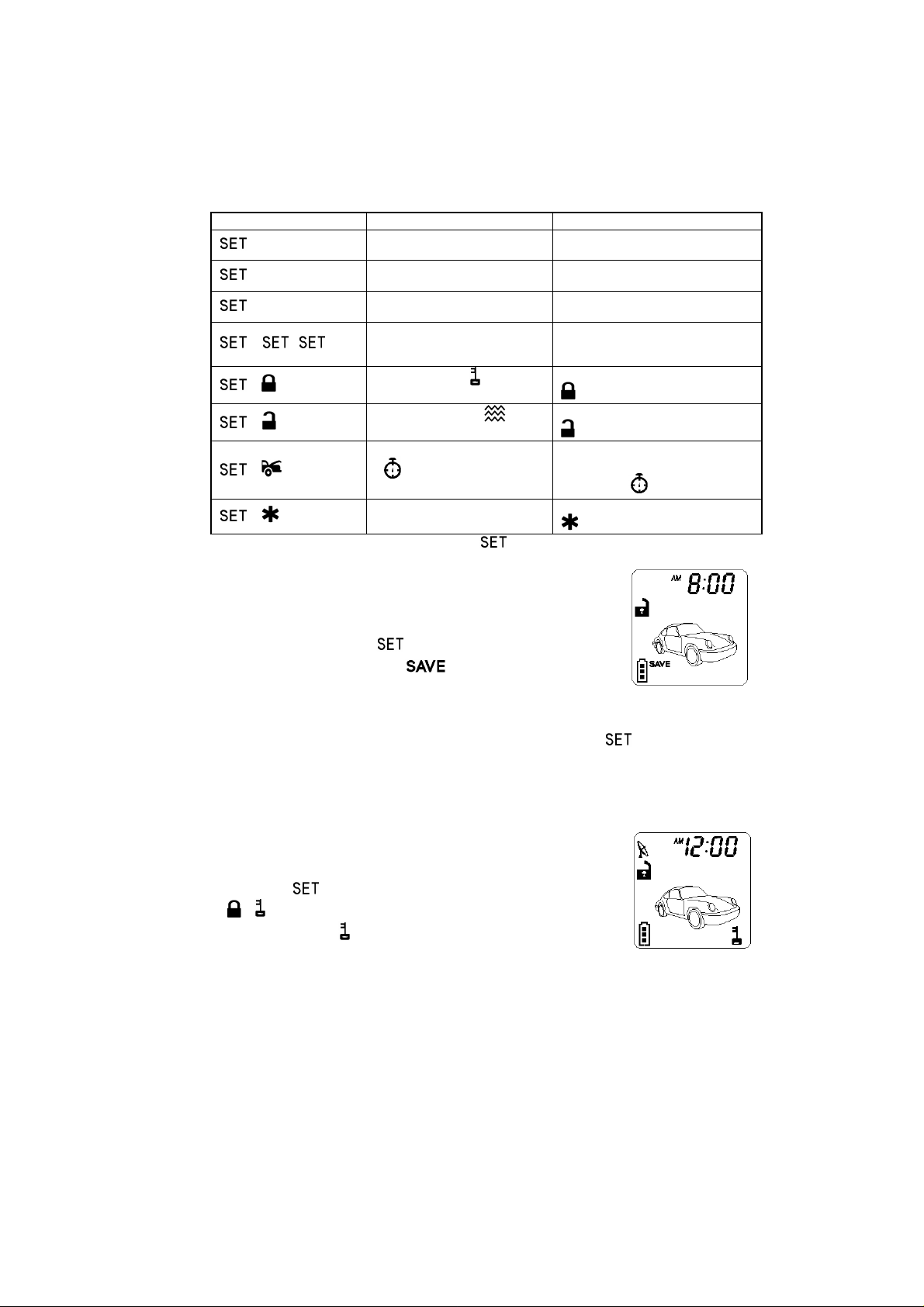
2. Power Save Mode: While in the power save mode, the
LCD remote transmitter uses “0” current to save the battery
power.
Entry: Press & hold the button for 5 seconds, one
melody will sound and the icon on the LCD screen
indicates entry of the “power save mode”.
Exit: Press any button of the LCD remote transmitter to
exit the “Power Save Mode”.
3. Clear the Flash Icon and Melody Sound: Pressing the button 3 times
within 3 seconds will clear the flash icon and the melody sound on the LCD screen
transmitter.
4. Stop The Trigger Melody Sound: While triggering the alarm the LCD screen will
alert the user through a melody sound and a flashing trigger icon. Press any button
on the LCD remote transmitter to stop melody sound only.
5. Button Lock: This is useful if you want to disable the
transmission function of the remote control temporarily to
prevent from any inadvertent pressing of buttons by others.
Press the button first, within 3 seconds press and hold
( ) button for 2 seconds to activate or cancel the button
lock function, the icon will displayed on the LCD screen to
show the LCD remote transmitter is on “Button Lock”
7
on the LCD screen to show
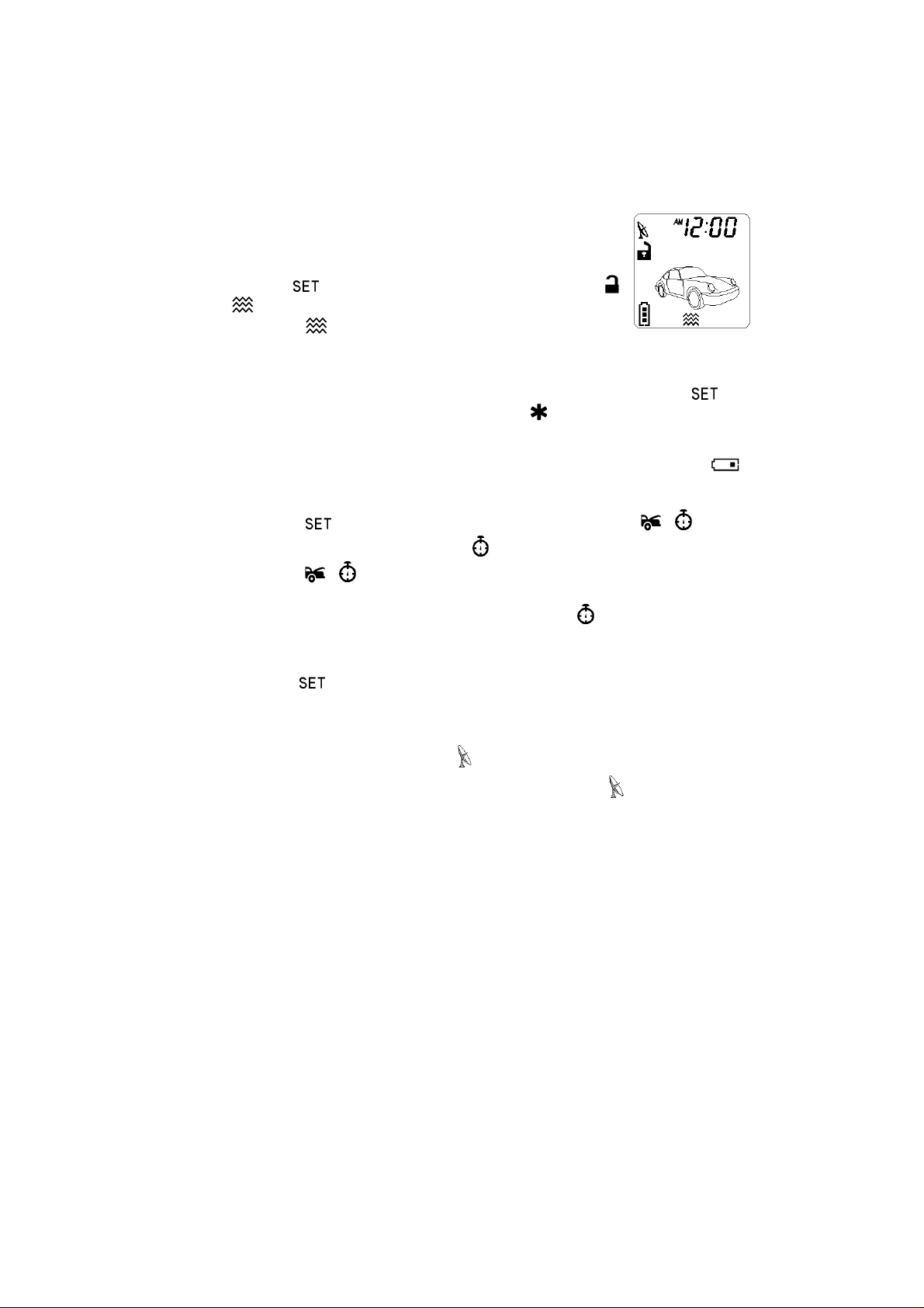
6. Vibration / Melody Mode:
This is useful when you are in a noisy place and it is difficult to
hear the beep sound from the remote control. In this mode,
the remote control vibrates itself if your security system is
triggered.
Press the button first, within 3 seconds press and hold
( ) button for 2 seconds to select the mode of vibration or
melody, the icon will displayed
the LCD remote transmitter is on vibration mode.
7. Enable / Disable Bi Sound While Pressing Button:
It has a short “bi” sound while pressing the button of the LCD screen transmitter
If you want mute the “bi” sound mute always while press button. Press the
button first, within 3 seconds press and hold the (Bi) button for 2 seconds to
disable the “bi” sound.
8. Low Battery Indication:
When the power of the battery weakens, it has two short “bi” sound and flash
icon while pressing the button of the LCD screen transmitter.
9. Set Up Fixed Count Down Timer:
1. Press the button first, within 3 seconds press and hold the ( ) button for
2 seconds, the LCD screen will show the icon and timer (i.e. 0:10),
2. Press the ( ) button again showing next order time on the screen (ie.0: 20),
press them again (ie.0: 30)…and so on.
3. After the timer is set the count down begins when the icon flashes
Note: 1.The count down period is fixed as 10 minutes, 20 minutes, 30 minutes, 1
hour, 1.5 hours and 2 hours maximum.
a. When the count down timer shows 0:00 it means to turn off the timer.
b. Press button for real time indication when the timer is counting down.
10. Out Of Range Indication:
The system will automatically check the range every 20 minutes after the unit is
armed.
1. If the user is within the range, the icon will display on the LCD screen.
2. If user is out of range, it has five short “bi” sounds and the icon will disappear
on the LCD screen.
8
 Loading...