

Night Guard Home Surveillance System C3-RS-665 User Manual
1
THIS PRODUCT IS DESIGNED FOR PROFESSIONAL INSTALLATION ONLY
C3-RS-665
PROFESSIONAL REMOTE CAR STARTER
&
2 CHANNEL SECURITY / ALARM SYSTEM
With Two Way Data Port
INSTALLATION MANUAL
Compatible

2
INSTALLATION WARNINGS
3
INSTALLATION DIAGRAM
4
Wiring Diagram
5
H7 16
-
Pin Wire H
arness
6
Wiring Description H1 Connector
6
Wiring Description H2 Connector
8
Wire Connector H3, H4, H6, H7 Connectors
9
Wiring Description H7 Connector
10
H3 Connector Valet Switch
15
H5 Door Lock Connector
16
H9 Serial Data Port connection RS
-
232 18 Remote Transmitter Programming
18
Feature ‘A’ Programming
19
Feature ‘B’ Programming
20
Feature ‘C’ Programming
22
Start Feature ‘D’ Programming
23
RPM Learn
24
Voltage Check Type
25
Timer Check Type
25
Return to Factor
y Default
26
Shutdown Diagnostics
27
Test your Install
27
Neutral Safety Switch Test
28
Key Sensor Circuit
39
Tech Line
31
TABLE OF CONTENTS:
Tachometer Learn Type
OPTIONAL EQUIPMENT:
XT-43 / Antenna Kit: This is an optional package that will enable your
unit to have two-way communications and paging capabilities with the
handheld remote. The optional kit includes a XT-43 LCD remote
transceiver as well as the TRX-76 two -way antenna module. Please see
your authorized Autopage dealer for information and pricing of this option.
23

3
INSTALLER WARNINGS
This Remote Starter with Alarm and Keyless Entry System has been
designed to be installed on fuel-injected vehicles with an automatic
transmission ONLY.
n Never install this remote starter on a manual transmission vehicle.
n This system must be installed and wired through a safety switch so it
will not start in any forward or reverse gear.
n Some automatic transmission vehicles mainly older GM vehicles with
a purple starter wire have a mechanical -type park safety switch instead
of electrical safety switch. The mechanical type does not interrupt the
starter circuit when the transmission is in any gear and does not offer the
100% level of safety required for remote starting purposes. Therefore,
our system should never be installed on any vehicle that uses a
mechanical type park safety switch.
n Once you install this system, you must verify that the vehicle will not
start in any forward or reverse gear, regardless of the type of vehicle.
n Read the operation manual for operating.
n Do not install any component near the brake, gas pedal or steeri ng
linkage.
n Some vehicles have a factory installed transponder immobilizer
system that can severely complicate the installation. There is a
possibility that this system cannot be installed on some
immobilizer-equipped vehicles.
n Most vehicles have an SRS air bag system. Use extreme care and do
not probe any wires of the SRS system.
n Disconnect the car battery before beginning work on the vehicle.
n Check behind panels before drilling any holes. Ensure that no wiring
harness or other components are locat ed behind the panels that would
otherwise be damaged.
n Do not use conventional crimp lock, bullet on any wiring. Poor wiring,
i.e. taped joints will possibly introduce unreliability into the alarm system
and may result in false alarms or incorrect operation. We suggest
soldering all connection points.
n Install the wiring neatly under carpets or behind trim to prevent
possible damage to wires.
4
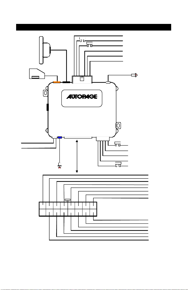
Red : System Power + 12 Volt
INSTALLATION DIAGRAM:
RX-300A
FUSE
FUSE
Violet : Starter Output
Red : 12 Volt Input
Red : 12 Volt Input
Yellow. Ignition 1 Output
Pink : Ignition 2 Output
Brown ACC Output
LED Indicator
Green : (-) Lock
(+) Unlock
Door Locks
Blue : (-) Unlock
(+) Lock
H7
Shock
Sensor
1 2 3 4 5 6 7
X
H4
H6
ANT.
H9
Data
H3
H5
Valet
DL
Valet
Switch
9 10 11 12 13 14 15 16
H1 6 Pin Wht.
C3-RS-665
Pink
H8
LED
H2 5 PinH7 16 Pin White
FUSE
Red/White : Parking light Input
White : Parking light Output
Black : System Ground
Brown : Siren (+)
FUSE
Orange
Wire: (-) 500mA Grounded Output When Armed
Blue Wire:(-) Zone 2 Negative Hood/Trunk trigger
White / Violet Wire: (+) Brake Switch Shut Down Input
Wire: (-) Neutral Safety Switch Input
Black / White
Yellow
Wire: (-) 200mA Ignition 3 Control Output
Blue / Black
Wire: (-) 200mA Accessory 2 Control Output
Brown / Black
Wire: (-) 200mA Ground When Running Output
Green Wire : Zone 3 (-) Negative Door Pin Trigger
8
Violet Wire: Zone 3 (+) Positive Door Trigger
Gray / Black
Wire: (-) 200mA Starter 2 Output
Gray
Wire: (-) 200mA Channel 2 (Trunk) Output
White Wire: (-) 200mA Dome Light Control Output
Wire: 2-Step Unlock(Fatory Default)/Factory Dsrm/Sensor By-pass
White / Black Wire: (-) Negative Hood Pin Safety Shut Down
White / Red
Wire: Tachometer Signal Input
5
Red:
Brown:
Black:
System Main Ground (
-
) White:
Red/White:
(+) Lock Pulse
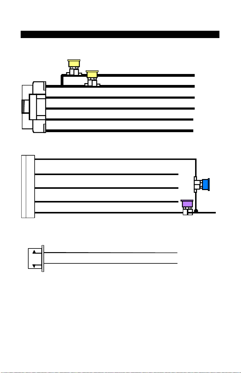
WIRE DIAGRAM:
#H1 6 PIN HEAVY GAUGE WIRE HARNESS
20A
20A
Red: Remote Start Power 1
Red: Remote Start Power 2
Violet: Starter (+) Output
Pink: Ignition 2 (+) Output
Yellow: Ignition 1 (+) Output
Brown: Acc/Heater (+) Output
#H2 5 PIN WIRE HARNESS
#H5. 3 PIN DOOR LOCK CONNECTOR
( - ) Unlock Pulse
1. Blue Wire
3. Green Wire
( - ) Lock Pulse
( + ) Unlock Pulse
6
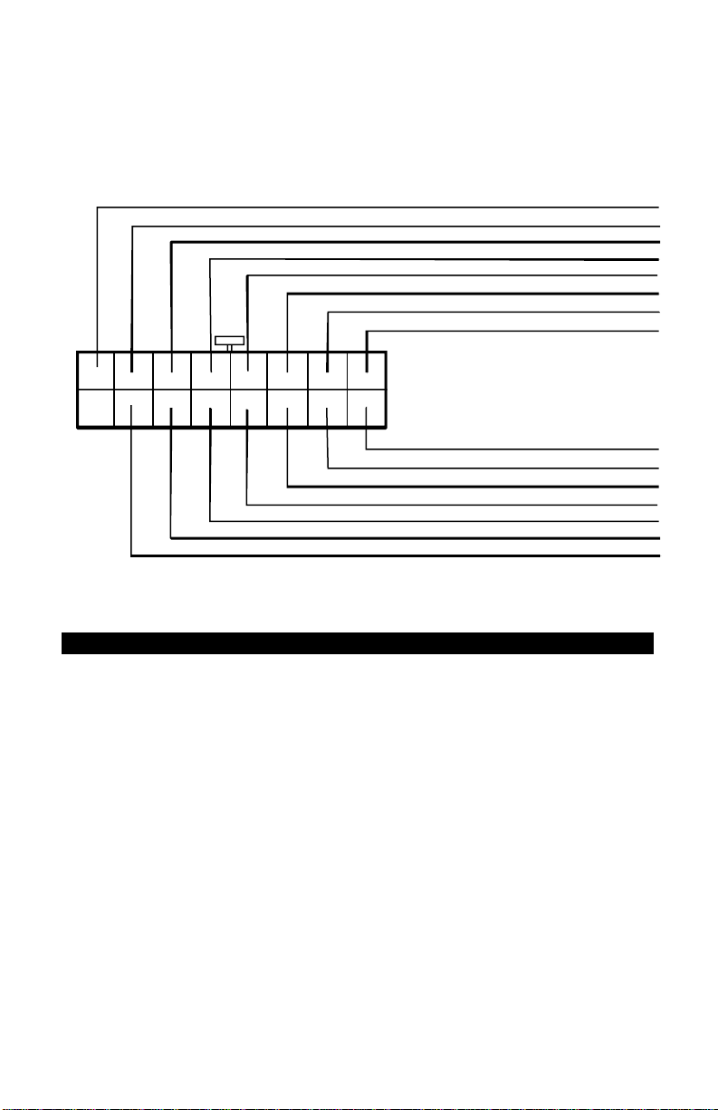
White / Red
Wire: Tachometer Signal Input
#H7. 16 PIN MOLEX CONNECTOR:
Orange
Wire: (-) 500mA Grounded Output When Armed
Blue Wire:(-) Zone 2 Negative Hood/Trunk trigger
White / Violet Wire: (+) Brake Switch Shut Down Input
Black / White
Yellow
Blue / Black
Brown / Black
Green Wire : Zone 3 (-) Negative Door Pin Trigger
Wire: (-) Neutral Safety Switch Input
Wire: (-) 200mA Ignition 3 Control Output
Wire: (-) 200mA Accessory 2 Control Output
Wire: (-) 200mA Ground When Running Output
1 2 3 4
X
9 10 11 12 13 14
5
6 7
8
15 16
Violet Wire: Zone 3 (+) Positive Door Trigger
Gray / Black
Gray
White Wire: (-) 200mA Dome Light Control Output
Pink
Wire: 2-Step Unlock(Fatory Default)/Factory Dsrm/Sensor By-pass
White / Black Wire: (-) Negative Hood Pin Safety Shut Down
Wire: (-) 200mA Starter 2 Output
Wire: (-) 200mA Channel 2 (Trunk) Output
WIRING
Keep wiring away from moving engine parts, exhaust pipes and
high-tension cable. Be sure to tape wires that pass through holes on the
firewall to prevent fraying.
CAUTION: Do not connect the wire harness to the control module until
all wiring to vehicle is complete.
H1: 6 PIN HEAVY GAUGE WIRING CONNECTIONS:
Remember that what the system does to start a vehicle is to duplicate the
functions of the ignition key switch! Below, we will explain the three basic
functions of the ignition switch. Since this installation will require analysis
of the ignition switch functions, we recommend making the three
connections below at the ignition switch harness directly.
Violet Wire—Starter Output
Careful consideration for the connection of this wire must be made to
prevent the vehicle from starting while in gear. Understanding the
difference between a mechanical and an electrical Neutral Start Switch
will allow you to properly identify the circuit and select the correct
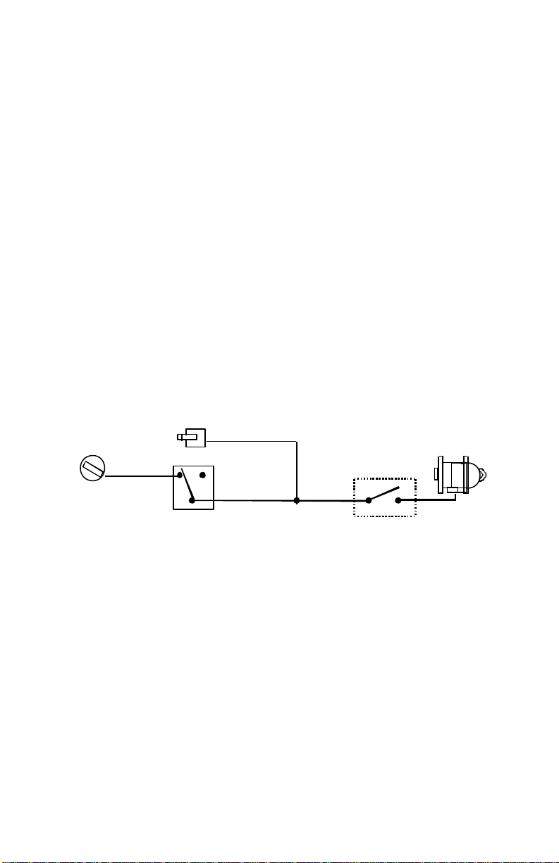
7
Start Cut Relay
VIOLET
Wire
“On”
Neutral Safety
“
Acc”
installation method. In addition you will realize why the connection of
the safety wire is required for all mechanical switch configurations.
Failure to make this connection properly can result in personal injury
and property damage.
In all installations it is the responsibility of the installing technician to
test the remote start unit and assure that the vehicle can not start via
RF control in any gear selection other than park or neutral.
In both mechanical and electrical neutral start switch configurations, the
connection of the VIOLET wire will be made to the low current start
solenoid wire of the ignition switch harness. This wire has +12 volts
when the ignition switch is turned to the “START” (CRANK) position
only. This wire has 0 volts in all other ignition switch positions.
NOTE: This wire must be connected to the vehicle side of the starter
cut relay (when used). For the electrical neutral switch configuration,
this connection must be made between the starter inhibit relay (when
used) and the neutral safety switch as shown in the following diagram.
Failure to connect this wire to the ignition switch side of the neutral
safety switch can result in personal injury and property damage. SEE
NEUTRAL START SAFETY TEST FOR FURTHER DETAILS.
Red Wire (2) — +12V Power Input
Yellow Wire – Ignition 1 Output
“Off”
Ignition
Switch
“Start”
(When Used)
Switch
Closed in Park or
Neutral Only
Starter
Remove the two 20A fuses prior to connecting these wires and do not
replace them until the satellite has been plugged into the control
module. These wires are the source of current for all the circuits the
relay satellite will energize. They must be connected to a high current
source. Since the factory supplies (+) 12V to the key switch that is used
to operate the motor, it is recommended that these wires be connected
there.
Note: If the factory supplies two separate (+) 12V feeds to the ignition
switch, connect one RED wire of the satellite to each feed at the switch.
Connect the YELLOW wire to the ignition 1 wire from the ignition switch.
The ignition wire should receive “12 volts” when the ignition key is in the
“ON” or “RUN” and “START” or “CRANK” position. When the ignition is

8
turned “OFF”, the ignition wire should receive “0” voltage. The
YELLOW wire must be connected.
PINK Wire – Ignition 2 Output
Some vehicles have [2] ignition wires that must be power. Connect the
PINK wire to the ignition 2 wire from the ignition switch. The ignition
wire should receive “12 volts” when the ignition key is in the “ON” or
“RUN” and “START” or “CRANK” position. When the ignition is turned
“OFF”, the ignition wire should receive “0” voltage. If the PINK wire is
not used, cap the end of the wire.
Brown Wire –Accessory Output (Heater /AC Output)
Connect the BROWN wire to the accessory wire in the vehicle that
powers the climate control system.
An accessory wire will show + 12 volts when the ignition switch is
turned to the “ACCESSORY” or “ON” and “RUN” positions, and will
show 0 Volts when the key is turned to the “OFF” and “START” or
“CRANK” position. There will often be more than one accessory wire in
the ignition harness. The correct accessory wire will provide power to
the vehicle’s climate control system. Some vehicles may have separate
wires for the blower motor and the air conditioning compres sor. In such
cases, it will be necessary to add a relay to power the second
accessory wire.
H2: 5 PIN WIRE HARNESS:
RED / WHITE WIRE –PARKING LIGHT RELAY INPUT —
The RED/WHITE wire is the input to the flashing parking light relay.
The connection of the RED/WHITE wire will determine the output
polarity of the flashing parking light relay.
If the vehicle you are working on has +12volt switched parking lights,
you don’t need connect this wire. This wire is already connected to
+12volt.
If the vehicle’s parking lights are ground switched, cut the RED/WHITE
wire, connect the RED/WHITE wire to chassis ground.
WHITE WIRE — PARKING LIGHT RELAY OUTPUT
(+12 V 10A OUTPUT) —
Connect the WHITE wire to the parking light wire coming from the
headlight switch. Do not connect the WHITE wire to the dashboard
lighting dimmer switch. (Damage to the dimmer will result). The
limitation of the WHITE wire is 10 AMP max. Do not exceed this limit or

9
4.
Wire / + 12Volts
damage to the alarm and parking relay will result.
BLACK WIRE — SYSTEM GRO UND –
This is the main ground connection of the alarm module. Make this
connection to a solid section of the vehicle frame. Do not connect this
wire to any existing ground wires supplied by the factory wire loom,
make the connection to the vehicle’s frame directly.
BROWN WIRE – (+) 2A SIREN OUTPUT –
This wire is provides power to the supplied siren. Connect the Brown
wire to the Red wire of the siren. Connect the Black wire of the siren to
a stable chassis ground.
RED WIRE — SYSTEM POWER (+12V CONSTANT) —
The RED wire supplies power to the system. Connect this wire to a
stable constant +12 volt source.
H8.2 PIN WHITE CONNECTOR (THE LED STATUS INDICATOR):
The led indicator status should be mounted in a highly visible area such
as top of the dashboard, on top of the shifter console or on the dashboard
face. Leave at least 6mm space behind the mounting location for LED
housing. Once a suitable location is chosen, drill a 6mm hole. Run the
LED wires through the hole then press the 2 pin LED housing into place.
Route the LED wires to the control module.
H4. Black 4-PIN CONNECTOR: WINDSHIELD MOUNT ANTENNA
The RF Antenna/Receiver Red connector is to be plugged in the Black
4-pin port on the main unit. The connector is to be plugged into the RF
Antenna/ Receiver plug. Mount the antenna/receiver with provided double
sided tape to center of windshield above rear view mirror, route the
antenna lead along the windshield pillar under the vehicle’s interior
windshield molding. Be sure to avoid mounting the antenna direc tly
behind the metallic tinted portion of the windshield.
H6. 4 PIN ORANGE CONNECTOR FOR 2 STAGE IMPACT SENSOR
H7: 16-PIN MOLEX WHITE CONNECTOR WIRE HARNESS:
1. Green Wire / Warn Away Input
2. Blue Wire / Instant Ground Trigger
3. Black Wire / Negative
Red
85 30 86
X
Yellow Wire
30 85 86 87
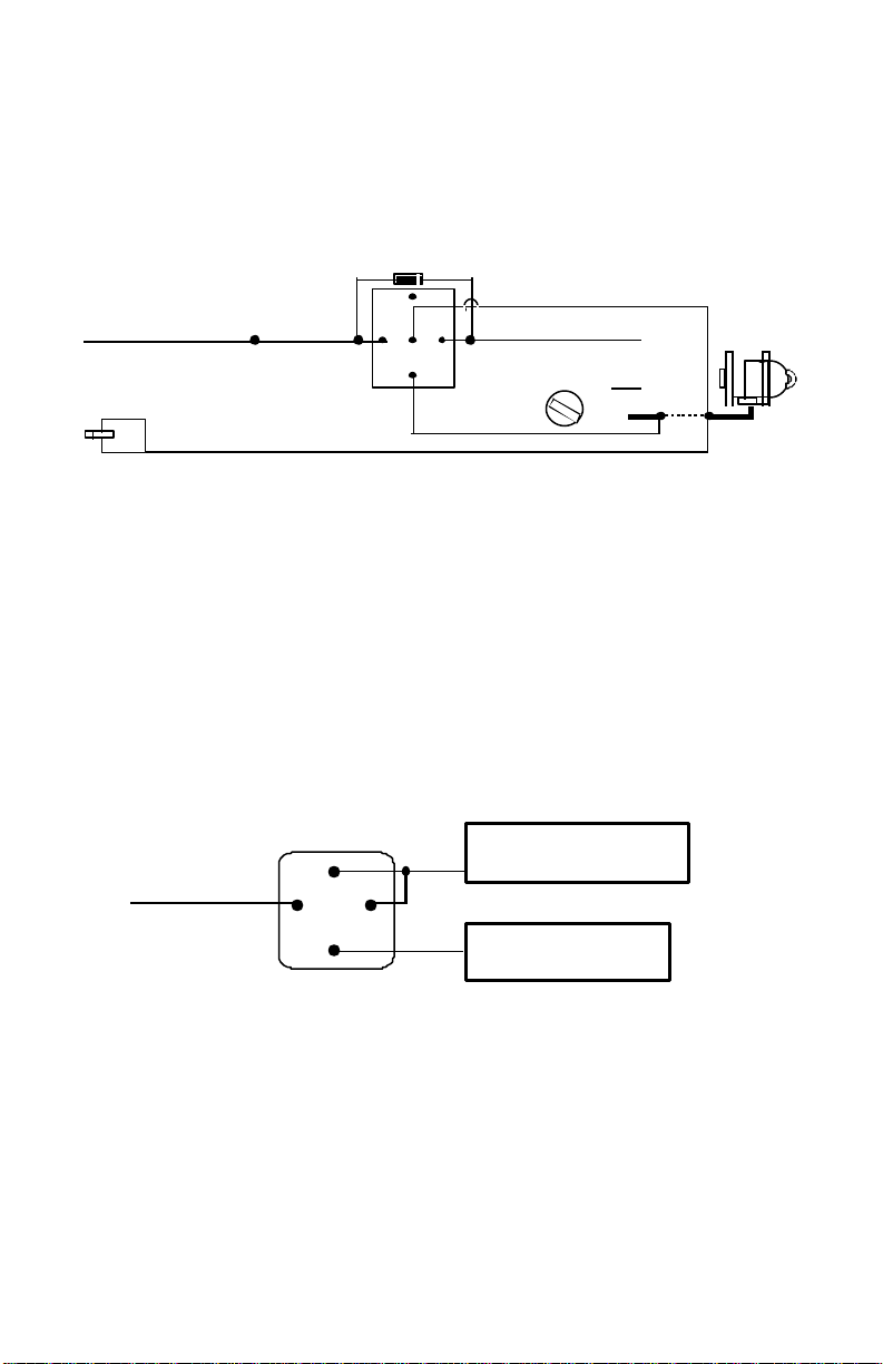
ORANGE WIRE – (-) 500ma GROUNDED OUTPUT WHEN
ARMED
This wire will become grounded when the alarm is armed. The
current capacity of this wire is 500mA. This output can control the
starter disable.
H7/1 : ORANGE wire
from control module
H1/1 VIOLET wire (Starter output)
form Heavy Gauge wire harness
White wire
IN4003 Diode
87
87a
Yellow wire
Violet wire
Red wire to
Ignition Switch
“Off”
“Acc”
“On”
Starter
Cut
“Start”
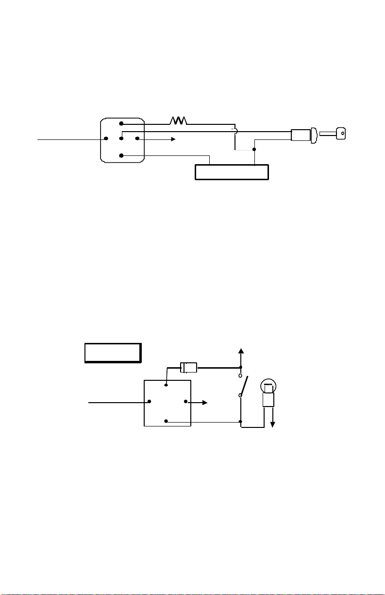
YELLOW WIRE: (-) 200ma IGNITION 3 OUTPUT –
This wire provides a 200mA (-) ground output that becomes active 4
seconds before the remote start unit is initialized, and remains grounded
while running.
Ignition 3 output:
Some newer vehicles use a third ignition wire, which is required to start
and keep the vehicle’s engine running. If this is the case, wire an IGN 3
relay (not supplied) as shown below:
Do not connect any vehicle circuits together; they are isolated for a
reason.
Output
87a
GM VATS KEY OVERRIDE:
If the vehicle has the General Motor VATS system installed, you will need
to by-pass the system while the vehicle is operating under the control of
the Remote Start Unit. To do this:
1. Measure the resistance of the resistor pellet on the ignition key then
select a resistor within 5% of the key’s value.
2. Locate the pair of VATS wires in the vehicle, usually a pair of thin gauge
wires running from the ignition switch to the VATS control module.
3. Connect the YELLOW wire from Remote Start Unit to Terminal #85 of
the relay. Connect terminal #86 of the relay to a fused +12 volt.
4. Cut (#1) wire (as shown), and connect the ignition switch side of the cut
10
+ 12 V Constant Fused
25A Capable
Ignition 3 Wire From
Ignition Key Switch
To + 12 V
87a
863087
85
(#2)
87a
86
Fuse
White Wire
wire to terminal #87a of the relay. Connect the other side of the (#1)
wire to terminal #30.
5. Connect the previously selected resistor from terminal #87 to the
second (#2) wire (as shown).
Matching Resistor
VAT wire (#1)
YELLOW wire
VAT wire
VATS control Module
Ignition
Switch
WHITE WIRE – (-) 200ma PROGRAMMING OUTPUT
(See Alarm Feature A - 6 Programming)
DOME LIGHT CONTROL OUTPUT (Factory Default Setting) —
This wire becomes grounded when the dome light control circuit is
active. The current capacity of this wire is 200mA. This wire can control
the operation of the interior lights. An optional 10 Amps relay can be
added to this system for interior lights operation.
a). Upon disarming, the interior lights will remain on for 30 seconds.
b). If the vehicle is violated, the interior light will flash for the
same duration as the siren.
Domelight
Courtesy
Door
87
85
30
Switch
+12V
FACTORY SECURITY REARM SIGNAL OUTPUT–
(See Alarm Feature A- 6 Programming)
This wire is designed to rearm a factory installed security system. This
wire will supply a pulse whenever the remote start times out or is shut
down using the transmitter and remote door locking.
HORN OUTPUT, (-) 200mA output
(See Alarm Feature A- 6 Programming)
This provides a negative output to be connected to the vehicles
negative horn trigger. This is a transistor output and should be
connected before the factory horn relay.
11
Light
 Loading...