

Night Guard Home Surveillance System C3-RS-603 User Manual

C3-RS-603
PROFESSIONAL REMOTE CAR STARTER
With Two Way data Port
INSTALLATION MANUAL
7/9/2008
RS-603 REV A.
Compatible
THIS PRODUCT IS DESIGNED FO R PR OFESSIONAL INSTALLATION ONLY
1

7/9/2008
TABLE OF CONTENTS
Installer Warning ……………………………………….
System Wiring Diagram ……………………………….
H1 - Main 6 Pin Heavy Gauge Harness ……………..
H2 – 6 Pin Harness ……………………………………
H3 – 8 White Connector Harness ……………………
Installation Factory Immobilizer Systems……………
H4 – 2 Pin Blue connector ……………………….……
H5 – 3 Pin Red Antenna/Receiver Connector ………
H6 – 3 Pin Door Lock Harness… ……………………
H7- SERIAL DATA PORT CONNECTION RS-232 Port
Remote Transmitter Programming …………………
Alarm Feature “I” Programming ……………………...
Alarm Feature “II” Programming ……………………..
Alarm Feature “III” Programming …………………….
RPM Learning ………………………………………….
Return To Factory Default Settings …………………..
To Remote Start The Vehicle ………………………….
Shutdown Diagnostics …………………………………
Trouble Shooting ……………………………………….
Testing Your Installation (Neutral Safety Switch)
Notes …………………………………………………….
This device complies with part 15 of the FCC rules.
Operation is subject to the following two conditions.
(1) This device may not cause harmful interference, and
(2) This device must accept any interference received,
including interference that may cause undesired operation.
3
4
5
6
6
8
9
9
9
10
11
11
12
12
13
13
13
13
14
14
16
RS-603 REV A.
2

7/9/2008
INTRODUCTION
INSTALLER WARNINGS
This Remote Starter System is desi gned to be insta l led on fuel-inj ected vehicles with an autom atic transmission ONLY.
Never install this remote st arter on a man ual transmission vehicle.
This system must be installed and wired through a safety switch so it will not start in any forward or reverse gear.
Some automatic transmission vehicles [mainly older GM vehicles with a purple starter wire] have a mechanical-type
neutral safety switch instead of electrical safety switch. The mechanical type does not interrupt the starter circuit when
the transmission is any gear and does not offer the 100% level of safety required for remote starting purposes. Therefore,
our system should never be installed on any vehicle that uses a mechanical type park safety switch.
Once you install this system, you must verify that the vehicle will not start any forward or reverse gear. Regardless of
the type of vehicle.
Read operation manual for operating and programming routine.
Do not install any component near the brake, gas pedal or steering linkage.
Some vehicles have a factory installed transponder immobilizer system that can severely complicate the installation.
There is possibility that this system cannot be installed on some immobilizer-equipped vehicles.
Most vehicles have an SRS air bag system. Use extreme care and do not probe any wires of the SRS system.
Disconnect the car battery before connecting work on the vehicle.
Check behind all panels before drilling any holes. Ensure that no wiring harness or other components are located
behind the panels that would otherwise be damaged.
Use conventional crimp lock or bullet connectors on wiring. Poor wiring, i.e. taped joints will possibly introduce
unreliability into the alarm system and may result in false alarms or incorrect operation.
Install wiring neatly under ca rpets or behind trim to prevent possible damage to wires.
For the wire operate s the c urrent more t han 10A. We sug gest s olderi ng all c onnect ion poin t. D oes not use crim p loc k
type connectors or wire nuts.
RS-603 REV A.
3
7/9/2008
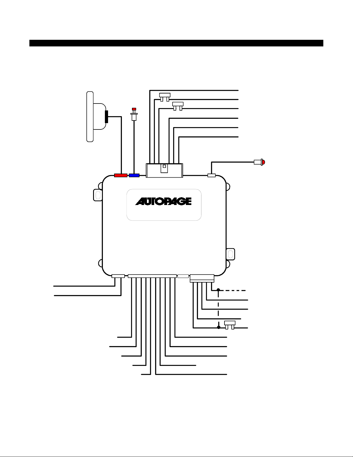
INSTALLATION DIAGRAM
RX-300A
H5
ANT.
Valet
Switch
H4
Valet
FUSE
FUSE
H1 6 Pin Wht.
H7
LED
Violet : Starter Output
Red : 12 Volt Input
Red : 12 Volt Input
Yellow. Ignition 1 Output
Pink : Ign i ti o n 2 Output
Brown ACC Output
LED Indicator
Green : (-) Lock
H6 DL
(+) Unlock
Door Locks
Blue : (-) Unlock
(+) Lock
White/Red : Tachometer Signal Input
White/Blue : Instant Start (-) Input
White/Black : Safety, Hood Pin Input (-)
Black/White : Neutral Safety Switch (-) Input
White/Violet : Safety Shutdown Brake Input (+)
C3-RS-603
H3 10 Pin White
H8
H2 5 Pin
Red/White : Parking light Input
White : Parking light Output
Black : System Ground
Brown : Programmable Output (-)
Horn (-) or Factory Rearm (-)
FUSE
Red : Sy stem Po wer + 12 Volt
Yellow : Ignition 3 Output ( 200 mA - )
Blue/Black : ACC 2 ( 200 mA - )
Pink : 200mA Programmable Output (-)
White : Ground When Running By-pass Control Output
Gray : CH 3 Trunk Release (-)
RS-603 REV A.
4
7/9/2008
V
WIRING
Keep wiring away from mo v i ng engi n e parts, exhaust pi p es and high-tens i on cable. Tape wires that pass th rou gh ho l es on
the firewall to prevent fraying. Watch out for sharp edges that may damage wires and cause a short circuit.
CAUTION: Do not connect the wire harness to the control module until all wiring to vehicle is complete.
H1: 6 PIN HEAVY GAUGE WIRING CONNECTIONS:
Remember! What the system does to start a vehicle, duplicates the function of the ignition key switch! Below, we will
explain the three basic functions of the ignition switch. Since this installation will require analysis of the ignition switch
functions, we recommend ma king the three connections below at the ignition switch har ness directly.
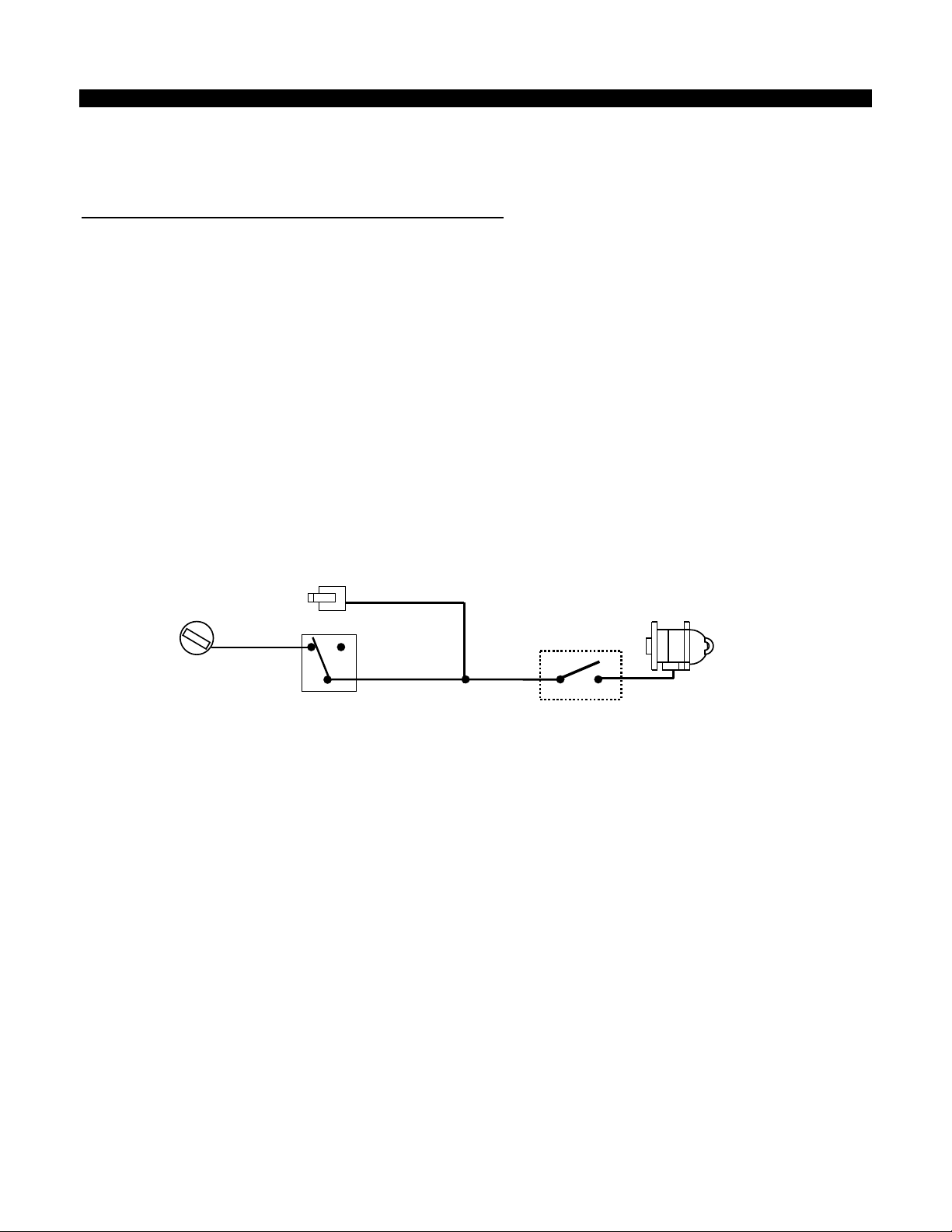
H1/1. VIOLET WIRE—Starter Output
Careful consideration for the connection of this wire must be made to prevent the vehicle from starting while in gear.
Understanding the difference between a mechanical and an electrical Neutral Start Switch will allow you to properly
identify the circuit and select the correct installation method. In addition you will real ize why the c on nect ion of t he s afet y
wire is required for all mechanical switch configurations.
Failure to make this connection properly can result in personal injury and property damage.
In all installations, it is the responsibility of the installing technician to test the remote start unit and assure that the
vehicle can not start vi a RF control in any gear selection other than park or neutral.
In both mechanical and electrical neutral start switch configurations; the connection of the VIOLET wire will be made to
the low current start solenoid wire of the ignition switch harness. This wire has +12 volts when the ignition switch is
turned to the “START” (CRANK) position only. This wire will have 0 volts in all other ignition switch positions.
NOTE: This wire must be connect ed to the vehicl e side of the sta rter cut relay (when used). For t he electrical neutral
switch configuration, this connection must be made between the starter inhibit relay (when used) and the neutral safety
switch as sh own in the following diagram.
Failure to connect this wire to the ignition switch side of the neutral safety switch can result in personal injury and
property damage. SEE NEUTRAL START SAFETY TEST FOR FURTHER DETAILS.
IOLET Wire
Neutral Safety
Switch
Closed in Park or
Neutral Only
“Off”
“Acc”
“On”
“Start”
Ignition
Switch
Start Cut Relay
(When Used )
H1/2 & H1/3. RED WIRE (2)-- +12V Power Input
Remove the two 20A fuses prior to connecting these wires and do not replace them until all connectors have been
plugged into the control module. These wires are the source of current for all the circuits the starter unit will energize.
They must be connected to a high current source. Since the factory supplies (+) 12V to the key switch that is used to
operate the motor, it is recommended that these wires be connected there.
Note: If the factory supplies two separate (+) 12V feeds to the ignition switch, connect one RED wire of the unit to each
feed at the switch.
H1/4. YELLOW WIRE – Ignition 1 Output
Connect the YELLOW wire to the ignition 1 wire from the ignition switch. The ignition wire should receive "12 volts"
when the ignition key is in the "ON" or “RUN” and "START" or “CRANK” position. When the ignition is turned "OFF", the
ignition wire should receive "0" voltage. The YELLOW wire must be connected.
H1/5 PINK WIRE – Ignition 2 Output
Some vehicles have [2] ignition wires that must be power. Connect the PINK wire to the ignition 2 wire from the ignition
switch. The ignition wire should receive "12 volts" when the ignition key is in the "ON" or “RUN” and "START" or
“CRANK” position. When the ignition is turned "OFF", the ignition wire should receive "0" voltage. If the PINK wire is not
used, cap the end of the wire.
H1/6 BROWN WIRE – Accessory Output (Heater /ACC Output) –
Connect the BROWN wire to the accessory wire in the vehicle that powers the climate control system.
An accessory wire will show + 12 volts when the ignition switch is turned to the “ACCESSORY” or “ON” and “RUN”
positions, and will show 0 Volts when the key is turned to the “OFF” and “START” or “CRANK” position. There will often
be more than one accessory wire in the ignition harness. If selected, the correct accessories wire will power-up the
vehicle’s c limat e control syst em. Som e vehicl es may hav e separat e wires for t he blower mot or and t he air c ondition ing
compressor. In such cases, it will be necessary to add a relay to power the second accessory wire.
Starter
RS-603 REV A.
5

7/9/2008
H2: 5 PIN WIRE HARNESS:
H2/1. RED/WHITE WIRE –PARKING LIGHT RELAY INPUT --
The RED/WHITE wire is the input to the flashing parking light relay. The connection of the RED/WHITE wire will
determine the output polarity of the flashing parking light relay.
If the vehicle you are working on has +12volt switched parking lights, you don’t need to connect this wire. This wire
already connected to +12volt. If the vehicle’s parking lights are ground switched, cut the RED/WHITE wire, connect the
RED/WHITE wire to chassis ground.
H2/2. WHITE WIRE -- PARKING LIGHT RELAY OUTPUT (+12 V 10A OUTPUT) --
Connect the WHITE wire to the parking light wire coming from the headlight switch. Do not connect the WHITE wire to
the dashboard lighting dimmer switch. (Damage to the dimmer will result). The limitation of the WHITE wire is 10 AMP
max. Do not exceed this limit or damage to the alarm and parking light relay will result.
H2/3. BLACK WIRE -- SYSTEM GROUND –
This is main ground connection of the alarm module. Make this connection to a solid section of the vehicle frame. Do
not connect this wire to any existing ground wires supplied by the factory wire loom; make the connection to the
vehicle's frame directly.
H2/4. BROWN WIRE – (-) 200mA PROGRAMMABLE OUTPUT (See Feature I - 3 Programming)
HORN OUTPUT – (Factory Default Setting)
This wire is provided to use the existing vehicle's horn as the alarm system's optional's warning audible device. It's a
transistorized low current output, and should only be connected to the low current ground output from the vehicle's
horn switch.
FACTORY SECURITY RE-ARM SIGNAL OUTPUT–
This wire is designed to rearm a factory installed security system. This wire will supply a pulse whenever the remote
start times out or is shut dowm using the transmitter and remote door locking..
(See Alarm Feature I - 3 Programming)
H2/5. RED WIRE -- SYSTEM POWER (+12V CONSTANT) --
The RED wire supplies power to the system. Connect this wire to a constant +12 volt source.
H3: 10-PIN MINI WHITE CONNECTOR WIRE HARNESS:
H3/1. WHITE/RED WIRE—Tachometer Signal connection—
This input provides the remote start system with information about the engine’s revolutions per minute (RPM). It can be
connected to the negative side of the coil in vehicle with conventional coils. In multi-coil and high energy ignition system
locating a proper signal may be more difficult. Once connected, you must Program the Feature
checking type” and teach the system the RPM signal.
To test for a tachometer wire, a multi-meter capable of test AC voltage m ust be used. The tachometer wire will show
between 1V and 6V AC at idle, and will increase as engine RPM increases. In multi-coil ignition system, the system can
learn individual coil wire. Individual coil wires in a multi-coil ignition system will register lower amounts of AC voltage.
Also, if necessary, the system can use a fuel injector control wire for engine speed sensing. Common locations for a
tachometer wire are the ignitions coil itself, the back of the gauges, engine computers, and automatic transmission
computers.
IMPORTAN T! Do not test tachometer wires with a test light or logic p robe. The vehic le will be damaged.
How to find a tachometer wire with your multi-meter
1. Set the ACV or AC voltage (12V or 20V is fine.)
2. Attach the (-) probe of the meter to chassis ground.
3. Start and run the vehicle.
4. Probe the wire you suspect of being the tachometer wire with the red probe of the meter.
5. If this is the correct wire the meter will read between 1V and 6V.
NOTE: No connection of this wire is required, if you use the voltage or timer checking type mode.
H3/2. WHITE/BLUE WIRE – (-) Instant Start & Turn Off Input.
This wire activ ates and turn s off t he remote st arter eac h time it sees a mome ntary ground s ignal. T his wire is no rmally
only used for testing during installation or when activating the module from an after-market system.
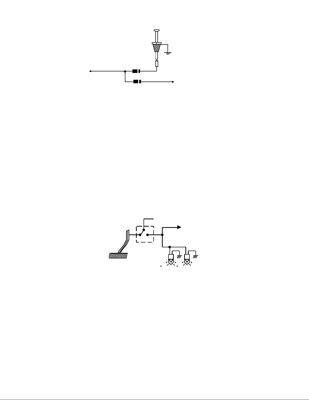
H3/3. WHITE/BLACK WIRE : (-) Negative safety shut down input
The WHITE/BLACK wire provides an instant shutdown for the remote start, whenever it is grounded. Connect the wire
to the hood pin switch previously installed. This wire must be routed though a grommet in the firewall and connected to
the hood pin switch.
Important! This connection is a safety wire and must be connected as shown and tested as specifiled. Failure to do
so may result in personal injury or property damage. See detail of wiring in the following diagram. This wire may also be
used if the vehicle brake light circuit switches ground to the brake lights. An isolation diode must be used for ground
switched brake light circuits and must be connected to the output of the brake switch.
RS-603 REV A.
6
III – 1 to “Tachometer
7/9/2008
Hood Pin Switch
To: White/Black Wire /
Negative safety
Diode
BLACK/WHITE WIRE (-)Neutral Safety Switch Input
H3/4
To Vehicle Brake Switch
(-)Remote Start Enable Toggle Switch Input
When the BLACK/WHITE wire is grounded, the remote start unit is operable. When this wire is open from ground, the
remote start is disabled. This wire must be connected to the vehicles Neutral safety switch!
1. The optional “remote start toggle switch” can be added on to temporarily disable the Remote Start Device, it can
prevent the vehicle from being remote started accidentally. This feature is useful if the vehicle is being serviced or
stored in an enclosed area. To disable the remote start, move the optional remote start enable toggle switch to the
OFF position. To enable the remote start, move the optional remote start enable toggle switch to the ON position.
2. This wire MUST be connected to the PARK/NEUTRAL switch in the vehicle. (See the TESTING YOUR
INSTALLATION GUIDE)
IMPORTANT NOTE: Directly connect the BLACK/WHITE wire to the “GROUND” when this wire is not used.
H3/5. WHITE/VIOLET WIRE : Positive safety shut down input
This wire provides an instant shutdown for the remote start, whenever it gets +12volts. If the brake lights switch in the
vehicle switches +12 volts to the brake light circuit, connect this wire to the output side of the brake switch. This will
allow the remote start to shut down if an attempt is made to operate the vehicle without the key while running under the
control of the remote start. In most vehicles, in order to shift gear, the brake pedal must be depressed. The brake input
will in turn cause the remote start unit to shut off. See below diagram.
Switch closes when
brake is depress
+12 volts from fuse box
To White/ Violet
wire
Brake light bulbs
H3/6. GRAY WIRE : (-)200mA Chaneel #3 output -
This will become a 1 second pulse ground by activate channel 3 on transmitter for two seconds, the current
capacity of this wire is 200 mA. This feature allows you to remote control trunk release or other electric device.
H3/7. WHITE WIRE: (-) 200 mA Ground output while the engine is starting or running. This wire can be used
to activate a by-pass module and will provide a ground output when the engine is starting or running
from the remote starter.
H3/8 PINK WIRE : (-) 200ma PROGRAMMABLE OUTPUT
(See Alarm Feat u r e I - 2 Pr og ramming)
FACTORY SECURITY DISARM SIGNAL OUTPUT –(Factory Default Setting) --
This wire is designed to disarm a factory installed security system. This wire sends a negative (-) 1 second pulse
upon a remote start and remote door unlocking. Some factory systems must be disarmed to allow remote starting.
In most cases, this wire may be connected directly to the factory alarm disarm wire. The correct wire will show
nagative ground when the key is used to unlock the doors or trunk. This wire is usually found in the kick panel area
in the wiring harness coming into the car body from the door.
START STATUS (Shock Sensor Bypass Control) OUTPUT–
RS-603 REV A.
7
 Loading...