

Page 1
Niezgodka GmbH
www.niezgodka.de
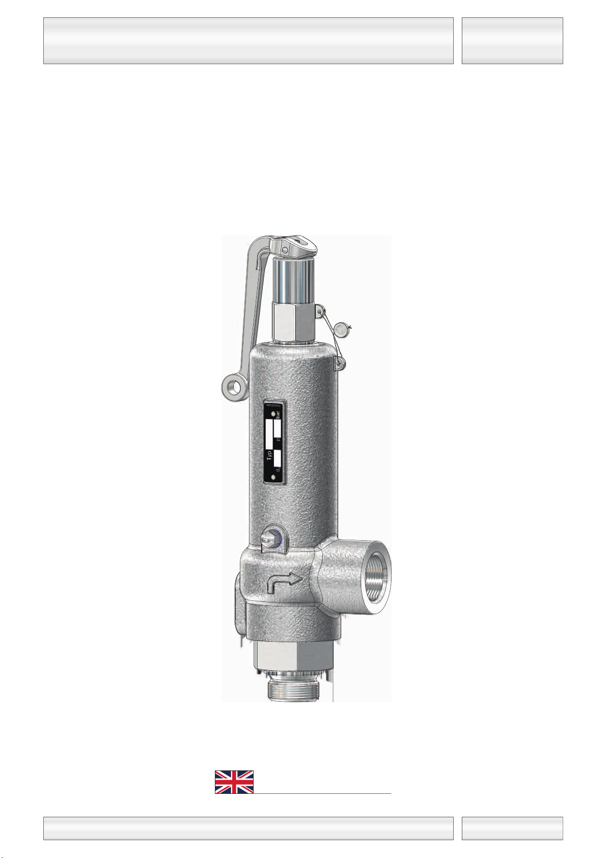
Relief-Valve, springloaded
Typ 21-E
04 / 2014
G 3/4 - G 1
for steam, gases and liquids in closed completion
Technical documentation
Typ 21
Englisch
GB
Page 2

Niezgodka GmbH
www.niezgodka.de
Armaturen
Niezgodka GmbH
Bargkoppelweg 73
22145 Hamburg
Germany
copyright © 2014 by Niezgodka GmbH Germany
+49 (0) 40 679 469-0
Armaturen
Page 3
Niezgodka GmbH
www.niezgodka.de
Relief-Valve, springloaded
IN 21-E
04 / 2014
Technical Data
Discharge capacities
Datasheet position
Datasheet
Approvals, certificates
Declaration of conformity
Terms of delivery and sale
General Terms and Conditions of Sale and Delivery
Headquarters and missions abroad
General Take-back conditions
Assembly, care and maintenance
Storage, transport and commissioning
Mounting Instructions
Contents
Maintenance Instructions
Troubleshooting operating problems
for steam, gases and liquids in closed completion
Typ 21
GB
Page 4
Niezgodka GmbH
www.niezgodka.de
RB
04 / 2014
Attention!
Niezgodka GmbH reserves the right to decide on taking back its products on a process-related and situation-dependent basis.
Basically, only such products will be taken back, as remain unused and are not older than two years (date of delivery).
The costs of the assembly services rendered as well as expenses incurred in connection with the take-back will be deducted.
Custom-made products will basically, not be taken back.
In cases of custom-made products, order cancellations after the start of production shall not be free-of-charge. Production
expenses that have already been incurred shall be invoiced on the basis of the status of production.
Spare parts and wearing parts shall be excluded from these conditions and will generally not be taken back irrespective of the
condition they are in.
General Take-back conditions
2
GB
Page 5
Niezgodka GmbH
www.niezgodka.de
¾
100
100
80
4,2
100
65 60 18 2901
600
1100
250
600
19
0,08
0,08
0,08
0,08
32 16 14
1 39 18 18
50
8
6
12,5
8
0,05
0,05
0,05
0,05
275
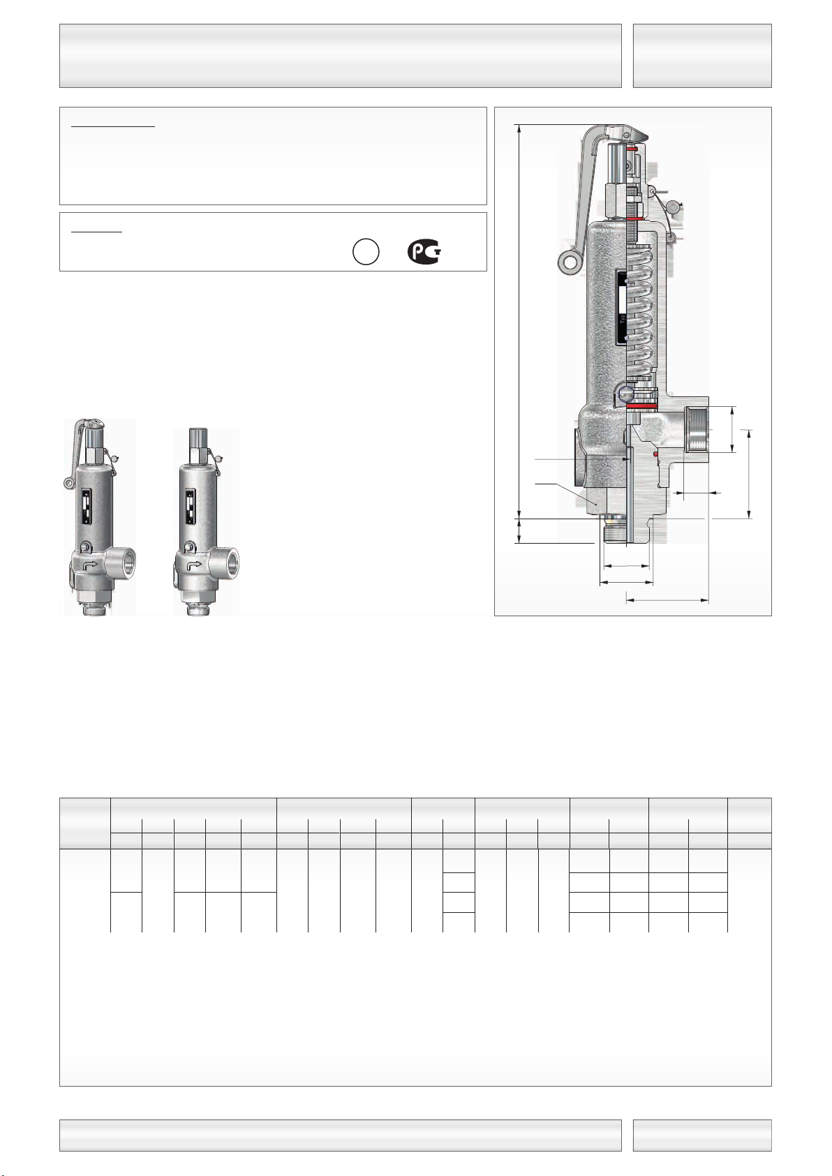
Relief-Valve, springloaded
K 21-E
04 / 2014
Inlet Outlet
Set pressure Weight
E S
E
[mm]
p
min.
[bar(g)]
p
max.
[bar(g)] ~ [kg]
Height ´H´
for
head
A
[mm]
[mm]d[mm]
l
(G)
[mm]
l
(NPT)
[mm]
S
A
[mm]
[mm]
A
t
(G)t (NPT)
Dimensions
[mm][mm]
doSW
C
[mm]
Coefficient
D/G
α
w max.
F
α
w
Size
other design on request
Connections:
Screwed connection: DIN ISO 228 / ASME B1.20.1
Typ 21.2:
soft seated
see techn. appendix: KWD-1
-60°C to 280°C
head Chead A
1.4571 / 1.4581
P E D
S
P
Standard version:
Material:
Temperature ranges
metal seated
Inlet body / Spring bonnet
Pressure Equipment Directive: 97/23/EG
Declaration of Conformity
Approvals:
for steam, gases and liquids in closed completion
Typ 21
Hl
A
d
o
E
SW
t
S
E
d
S
A
GB
Page 6

Niezgodka GmbH
www.niezgodka.de
100
120
140
160
180
200
230
260
290
320
360
400
440
480
520
560
600
650
700
750
800
850
900
950
1000
754
826
896
954
1011
1066
1143
1216
1284
1349
1431
1508
1582
1652
1719
1784
1847
1922
1995
2065
2133
2198
2262
2324
2384
569
690
815
952
1100
1261
767
925
1086
1250
1415
1583
1840
862
972
1085
1241
1403
1571
1745
1927
2117
2316
3273
3585
3873
4156
4341
4629
4964
2161
2283
2398
2543
2681
2812
2937
3057
3172
3284
131
159
187
219
253
290
176
213
250
288
326
365
424
484
547
610
698
789
883
982
1084
1191
1302
1450
1607
1775
1956
2152
2366
2601
2862
1100
2501 3486
p
e
[bar(g)]
0,08
α
w max.
α
w
0,05 0,08
α
w max.
α
w
0,05
6 8
0,08
α
w max.
α
w
0,05
12,5
Relief-Valve, springloaded
V 21-E-1
04 / 2014
Water
20°C
[kg/h]
3
n
Air
0°C
[m /h]
Steam
[kg/h]
Water
20°C
[kg/h]
3
n
Air
0°C
[m /h]
Steam
[kg/h]
Water
20°C
[kg/h]
3
n
Air
0°C
[m /h]
Steam
[kg/h]
Size
d
o [mm]
Fluid
Coefficient of
discharge
Discharge capacities
for steam, gases and liquids in closed completion
Typ 21
GB
Page 7
Niezgodka GmbH
www.niezgodka.de
Relief-Valve, springloaded
M 21-E
04 / 2014
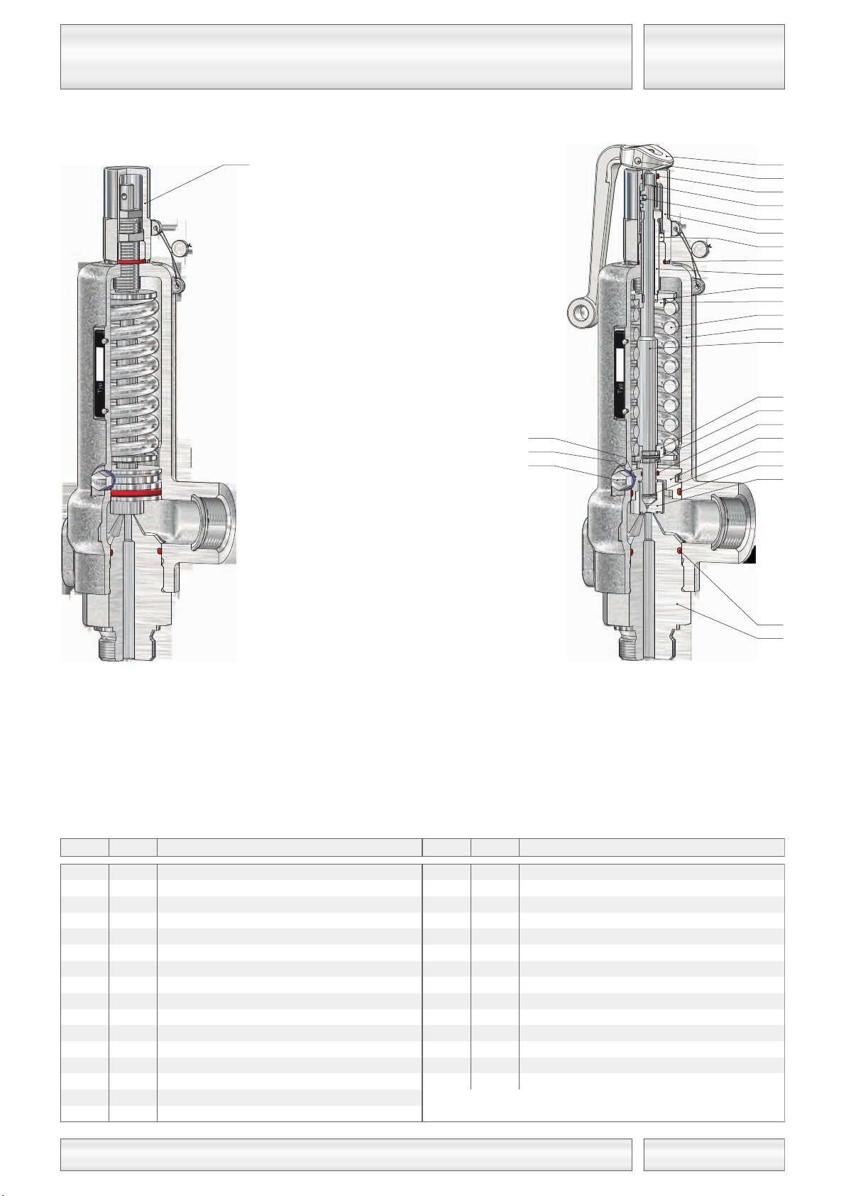
001
030
060 *
080
085
inlet body
spring bonnet
disc, complete
spindle
adjusting screw
005 * o-ring
132 groove pin1
122 coupling
084 springplate, lower
133 groove pin
121 lifting cap
1
1
1
1
* expendable parts
1
1
056 lock nut2
057 screwed pin2
059 * o-ring2
1
560
disc
1
062
soft sealing
1
063
disc ring
1
1
1
086 lock nut1
1
1
082 springplate, upper1
081 spring1
125 lifting lever
130 * o-ring1
131 * o-ring1
Item DescriptionPiece Item DescriptionPiece
head Ahead C
120 cap1
112 split ring1
097 glide ring1
100 * o-ring1
101 * o-ring1
092 lock ring1
089 guide plate1
for steam, gases and liquids in closed completion
Typ 21
120
057
059*
056
125
133
131*
122
132
121
086
130*
085
097
082
081
030
080
084
112
100*
089
092
101*
060*
005*
001
GB
Page 8
Niezgodka GmbH
www.niezgodka.de
≥ 0,5%
Manual Instructions
EB_SV/EV
04 / 2014
Safety- / Relief-Valves are instruments of high quality and should be handled with care. The disc (060) and the seat (001 / 003) are
manufactured out of hardened or tempered steel and are grinded and lapped to give positive sealing. If the valve disc and seat were handled
improper or faulty they will get defect.
Function:
When the pressure before the Safety- / Relief-Valves reaches the set pressure, the valve commences to lift, i.e. open a little at first to discharge
a small amount of medium. If the pressure continues to rise, it will open further and more medium is discharged. At a max. pressure increase of
10% (5%), the stroke required for the mass flow to be discharged is reached. When the pressure drops to 10% (gases / vapours and gases) or
20% (incompressible medium / liquids) below the set pressure, the valve closes and no fluid escapes anymore.
Maintenance:
Safety- / Relief-Valves are designed regarding design and construction in such a way that an optimum of quality is achieved, and that they are
easy to service. A minimum of care and maintenance is the result when our fittings are applied. The maintenance work, however, is permitted to
be carried out only by trained personnel.
We suggest the following:
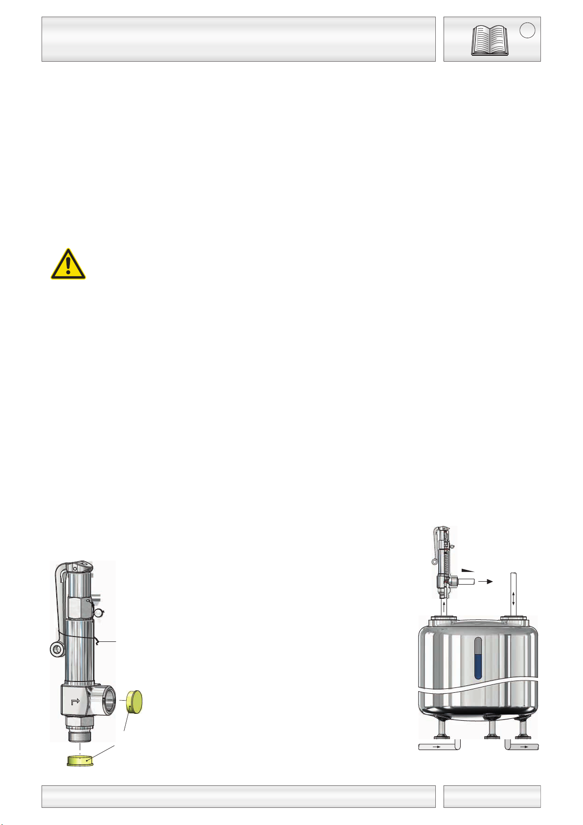
In and outlets are provided with protective caps. These are to be removed before the installation. The valves may not be thrown
(leakage/failure in operation may result).
The whole system has to be rinsed before installation of the valve! If the plant should not be sufficiently purified or in the case of an
inappropriate assembly, the valve may be leaky already upon first response. The assembly of the threaded valves should be
carried through without using hemp or PTFE-tape. Metal sealing rings are to be preferred.
The Safety- / Relief-Valves have to be fitted vertically with the spindle (080) in an upright position. For a perfect function in the long
run it is also necessary to install the valve without tension into the plant.
In order to prevent the misuse of the lifting lever (head "A") it is binding wire in the closed position. If the mounting is correct and the
pressure is arrived at 85% of the adjusted set pressure the lifting device can be set in motion. The same is valid for lifting heads "B",
"D" and "E": To check the head type "C", the valve should be exposed to response pressure only externally by gas or with a
sufficiently purified plant.
For the valves (particularly) used in steam applies:
Routining the functioning by operating the ventilation at least every 4 weeks.
Foreign substances in the pipeline (such as jointing materials) will seriously damage the seating area of the valve. By operating the
lifting device small deposits of foreign matters can be effectively cleared from the valve disc (060) and seat (001 / 003).
(In doing this, a clear stroke of the valve spindle (080) must be achieved).
The feed nozzle for the valve must be as short as possible and must have at least the same nominal width as the valve.
The pressure loss in the inlet pipe should not exceed 3 % of the set pressure.
The blow-off pipe should be mounted with downward gradient in sufficient dimensioning. Resulting condensate must be exhausted
safely. Inside the blow-off pipe the backpressure of max. 10 % of the set pressure should not be exceeded.
The operating pressure of the plant should be at least 5% below the closing pressure of the valve (pressure peaks in case of piston
pumps must be taken into consideration!). Thus a perfect closing of the valve after blow-off is ensured.
binding wire
protective caps
filling line emptying line
for safety and relief valves
15
GB
Page 9
Niezgodka GmbH
www.niezgodka.de
Storage, transport and commissioning
LTI
04 / 2014
General:
Observe the following storage instructions:
Environment:
Temperatures:
Transportation:
Commissioning:
Delayed initial opening caused by so-called sticking (adhesion) effect of the seating (001 / 003) and disc (060) is quite normal after
transportation and longer storage of valves with a preset response pressure. This applies both to metal/elastomers sealing faces and highly
polished metal/metal faces.
When the valve has been fitted the sealing faces are separated by pressurisation higher than the actual response pressure and by operating the
venting lever.
The valve, together with the preset pressure response, is now fully functional, taking the permissible pressure increase/closing pressure into
consideration.
Attention!
• The regional safety regulations are to be observed.
• The material, pressure, temperature and flow direction specifications must be checked prior to commissioning.
• The valve data are to be checked for position (arrangement) in the system.
• Residues in pipelines and valves (welding beads, grinding dust, dirt etc.) lead to leakage or damage.
• Touching the valve can give rise to the risk of injury when it is operated at high medium temperatures of (>50°C)
or low temperatures of (>0°C).
• Remove the blocking screw (149), which may have been used, from the cap (120).
• Remove protective caps and lever fixtures prior to commissioning.
• Sticking, freezing or blockage of the valve is to be avoided without fail.
• When a blow-out pipe is not used, the medium can suddenly escape from the valve outlet aperture. Hazard!
• Large amounts of flow noise can be heard when blowing out.
Care is to be taken to ensure prior to putting a new system into operation or restarting a system that has been subject to repair or
conversion that:
• All work is completed in an orderly manner!
• The valve is in the correct function position.
• Safety devices are in place.
NI-Valves are high quality products which must be treated with care. The sealing faces on the seating (001 / 003) and disc
(060) are hardened, annealed, ground and lapped. Improper handling can cause them to be damaged, resulting in leakage
and inoperability. They must therefore be protected against shocks (throwing, impacting, hitting etc.). On valves equipped with
a venting lever etc., the lever must not be misused as a carrying handle. All valves are to be properly secured to prevent them
falling over or falling down in the course of transportation, fitting and maintenance.
Places of storage must be clean and dry.
NI-Valves should be stored at temperatures between 5°C to 35°C, the best being 10°C to 20°C. The instructions for disc
sealing must be complied with in the case of soft sealing valves.
Only use suitable packing materials for transportation. Inlet and outlet apertures are to be protected for transportation purposes
by caps or plugs which are only to be removed shortly prior to assembly.
15
GB
Page 10
Niezgodka GmbH
www.niezgodka.de
Instructions for maintenance
WA_SV/EV
04 / 2014
Maintenance:
NI-Safety- / Relief Valves are designed regarding design and construction in such a way that an optimum of quality is achieved, and that they are
easy to service. A minimum of care and maintenance is the result when our fittings are applied.
For the replacement of spare-parts it is also recommended to have this work executed only in an authorized workshop. If no suitable repair
means are available it is best to return the complete safety valve to the plant of Niezgodka GmbH. All spare-parts supplied by us are suitable for
the installation into our safety- / relief valves without restriction. It is, however, necessary to state in the order the number of the delivery
note/invoices or the commission number since the safety- / relief valves supplied are adjusted to their particular application.
Test intervals:
The minimum test intervals for safety- / relief valves especially activated by steam are four weeks. Test intervals for other applications must be
determined by the user in compliance with the operation conditions. Tests and examinations are to be executed at least during each internal or
external examination of the pertaining pressure device.
Regular releasing:
The release device of safety- / relief valves must be actuated regularly in order to examine the function and to remove soiling, if any.
This is possible manually in the case of valves with valve head “A”, “B”, “E”, “M” and “H” at a pressure rate ≥ 85% of the set pressure.
Valves with head “C” (gas tight with cap) should be brought to the release pressure only externally with gas or at a 100% clean device.
Leaks:
Leaks may be caused in the case of safety- / relief valves due to soiling between seat (001 / 003) and disc (060) or through damage of the
sealing surfaces that were caused on account of soiling in the medium or by the medium itself. Soiling can be removed by causing the safety- /
relief valves through releasing to blow off. If it fails to remove the soiling in this way, it must be assumed that the sealing surfaces are damaged.
The damage can be removed by post-processing (lapping). The work involved should be carried out only in the plant of the manufacturer or by a
workshop authorized by the manufacturer. Leaks may also occur when the operating pressure is too close to the reaction pressure. In such a
case, the design of the safety- / relief valves is to be examined.
Corrosion protection:
NI-Safety- / Relief Valves that are not corrosion protected are provided with a protective paint cover in the plant of the manufacturer. In a moist
environment it may become necessary to apply later additional corrosion protection layers. In this case it must be seen to it that the function of
movable components (e.g. spindle (080) and disc (060)) is not affected. Heads with manual release, the blowing off space and freely blowing off
safety- / relief valves should not be painted later. For heavily corrosive conditions, safety- / relief valves made of special steel should be used.
For fürther information, see our website
Attention!
Care must be taken to ensure that the system is depressurised prior to assembly, dismantling or opening of the safety/relief valve.
The remaining dimensions and seal properties, preloading forces, tightening torques etc. are to be determined by the user
themselves in accordance with the operating instructions. In doing so special attention must be paid to the following:
Medium residues in the safety/relief valve or in the spring cap represent a serious chemical burning, burns and poisoning hazard.
It must, therefore, be established prior to removing a valve from the plant which medium could be present in the safety/relief valve.
Appropriate safety measures must be taken.
for safety and relief valves
15
GB
Page 11
Niezgodka GmbH
www.niezgodka.de
Troubleshooting operating problems
FB_SV/EV
04 / 2014
Use a heating jacket!
Fault RemedyPossible cause
Remove flange and threaded protection
caps
Icing incurred when blowing out
Either replace or readjust safety /
relief valve
The setting pressure is too high / too low
Regular brief venting or heating /cooling of
the safety / relief valve
Viscous / sticky / hardening medium
Replace safety / relief valvebellow designe (161) faulty, no longer
compensates counter pressure
Remove spindle blocking screw (149)
Safety / relief valve doesn’t respond
It must be possible to briefly vent the
safety/relief valve over ≥ 85% of response
pressure
Pressure below ≤ 85% of response
pressure
Can’t be vented
The operating pressure must be
≤ 90% of response pressure
The operating pressure is
≥ 90% of response pressure
Brief venting of safety / relief valve,
replace if necessary
Contamination between seating (001 / 003)
and disc (060)
Safety / relief valve seating leaky
Risk of caustic burning, burning and / or
poisoning
Use smaller safety / relief valveover-dimensioned safety / relief valve
Use larger valveSafety / relief valve too small
Injuries caused by fluid residues
Flutter
Opening pressure too high
Spindle blocking screw (149) not removed
Flange and threaded protection caps have
not been removed
Establish which fluid is in the safety /
relief valve before it is dismantled
for safety and relief valves
15
GB
Page 12
Niezgodka GmbH
www.niezgodka.de
Declaration of Conformity
KON-3
04 / 2014
1
3
4
5
11
13
14
18
21, 22
24
33
35
9
91
90
SE-ÜR-91
DN 50
DN 25
DN 15
DN 10
DN 50
DN 25
DN 20
DN 50
DN 25
DN 25
DN 25
DN 50
DN 50
DN 50
DN 25
-
-
-
-
-
-
-
-
-
-
-
-
-
-
-
DN 10
DN 15
DN 8
DN 8
DN 10
DN 15
DN 10
DN 10
DN 20
DN 15
DN 15
DN 15
DN 25
DN 15
DN 15
DN 15
ManufacturerHamburg, 02.03.2014 authorized subscriber
The signing manufacturer confirms by this declaration that design, manufacturing and inspection of these pressure equipments
are in compliance with the directive 97/23/EC as well as with the national specifications DIN EN 12266, DIN EN 12516,
AD 2000-leaflet A4 match:
The below pressure equipments are falling under Article 3, Paragraph 3, and it is not allowed to provide them with
CE-marking which is spezified in annex VI.
To document the conformity with the directive 97/23/EC directly at the pressure equipment, it will provide with the
following sign.
Type Nominal Size Inlet Pressure accessory
Management: Dorrit Niezgodka, Verena Niezgodka-Seemann
Registered at the District Court Hamburg, HRB No. 29139
Relief-Valve
Relief-Valve
Relief-Valve
Relief-Valve
Relief-Valve
Relief-Valve
Relief-Valve
Relief-Valve
Relief-Valve
Relief-Valve
Relief-Valve
Relief-Valve
Vacuum-Relief-Valve
Vacuum-Relief-Valve
Vacuum- and Pressure-Relief-Valve
Overflow-Control-Valve
PED: Pressure Equipment Directive
SEP: Sound Engineering Practice
P E D
S
P
Niezgodka GmbH
Bargkoppelweg 73
DE-22145 Hamburg
according to Annex VII of Directive (PED) 97/23/EC
1
GB
Page 13

Niezgodka GmbH
www.niezgodka.de
General Terms and Conditions of Sale and Delivery
AVL
04 / 2014
1. General
The following terms and conditions are part of any
agreement for supply.
Any deviations from these conditions will be effective
only if we have granted our prior written consent.
Conflicting or interfering purchase terms and
conditions of the Purchaser shall be invalid even if we
do not explicitly contradict to the conflicts or
interference.
The unconditional acceptance of the goods does not
invalidate the exclusive validity of these terms and
conditions.
Should any individual provision be void, illegal or
unenforceable, the validity of the remaining
provisions hereof shall in no way be affected.
2. Quotations / Orders
Our quotations are subject to confirmation regarding
price, quantity, delivery deadline and availability for
delivery.
Orders as well as verbal agreements shall become
binding for us only by our written confirmation.
Catalogue pictures and illustrations in quotations are
not binding in as far as a modification of design,
measurements and weights is subject to change
without notice.
3. Price and Payment
The prices shall be effective ex factory Hamburg,
without packaging material, unless agreed on
otherwise.
Payments must be made by money transfer. The
terms of payments listed in the order
acknowledgement or invoice resp. shall be in effect.
In case of delayed payments, we are entitled to
charge interest of delay.
4. Delivery Period
The delivery period results from the agreements
reached by the parties of the contract.
Meeting the deadline by the supplier requires that all
commercial and technical matters have been settled
first and the buying customer has met all his
obligations. Failing that, the delivery time will be
prolonged appropriately.
Meeting the deadline of the delivery period is
warranted under the reservation of our being
supplied correctly and in time.
Claims cannot be made against us in case we fail to
meet a delivery deadline.
5. Passage of Risk
The risks will pass on to the Purchaser at the latest
with the dispatch or collection of the goods to be
delivered, even a case of partial deliveries.
We will conclude a transportation insurance policy
only if the Purchaser has given explicit written order
to do so.
Partial deliveries are permissible.
6. Retention of Title to Ownership
The right of ownership in the item supplied will
remain with the Supplier pending receipt of all
payments resulting from the delivery contract.
The Purchaser assigns already now the claims
resulting from this transaction to the Seller if the
item supplied is resold prior to our receipt of
payment (extended retention of title to
ownership).
Behavior contrary to the contract, especially in
case of default of payment, entitles us to take
back the items supplied, after having sent a
reminder, and the Purchaser is obliged to
surrender the items.
The assertion of the retention of title to
ownership as well as the attachment of the items
supplied by us shall not mean the rescission of
contract by us.
Filing insolvency application on the part of the
Purchaser entitles us to withdraw from the
contract and request the immediate return of the
items supplied.
7. Warranty
Starting with the date of delivery, the statutory
warranty period is applicaple for our products.
Wearing parts are excluded from this provision.
The products are subject to a density test as well
as a final test after their assembly and pressure
adjustment. All tests are performed pursuant to
standard by means of air or water resp., on
examined and calibrated test stations / test
devices.
Test documents of the individual acceptance
tests / material tests will be kept in the archives
for a minimum period of ten years.
8. Liability
Notices of obvious defects must be given in
writing immediately after their detection, at the
latest, however, within eight (8) days after
receipt of the item supplied.
Other defects subject to liabilty must be reported
immediately after detection in writing.
If we decline to accept a claim for a warranty, the
claim made by the Purchaser is regarded as
waived unless contradicted within one month in
writing.
Accepted defects will be repaired without charge
in our Hamburg works or replaced by new items
without charge. The parts subject to complaint
have to be returned to us without charge.
We will bear the direct costs of repair or of the
replacement parts; in case the complaint is
justified, we will bear the costs of the
replacement part.
Delivery of new goods is effected on principle
subject to thorough examination of the defect
and its result with reference to the part
complained about. The Purchaser has to
reimburse the costs of examination if the claim
proves to be unjustified.
We are not liable for consequential damage as a
result of slight negligence unless a warranted
property has not been supplied.
In addition, no warranty is accepted in the following
cases: unsuited or improper use, wrong assembly or
putting into operation by the Purchaser or a third
party, normal wear, incorrect or negligent treatment,
improper maintenance or unsuitable operating
equipment.
We are not liable for consequences of unprofessional
repairs by the Purchaser or a third party. The same
applies to modifications of the items supplied without
our prior consent.
Assembly instructions are aimed at the know-how of
qualified personnel. Only skilled personnel should,
consequently, perform the assembly work.
9. Returns
Goods supplied are allowed to be returned only after
our prior written consent. Return shipping must be
made by prepaid freight.
In case of contract cancellation or returns of the
goods for reasons the Purchaser is liable for, the
Purchaser will be charged with the necessary costs
incurred relating to the return as well as the
dismantling performed.
Custom-made items as well as spare parts can, on
principle, not be taken back.
10. Statutory Limitation
All claims of the Purchaser, for whatever legal
reasons, are limited to 12 months.
11. Documentation
Any documentation included in the supply is not
allowed to be altered. Manufacturer marking on
products is not allowed to be removed. Further use
by a third party is only permitted with our expressed
consent.
12. Place of Jurisdiction
Place of performance for delivery and payment and
place of jurisdiction for both contract parties is
Hamburg.
Management: Dorrit Niezgodka, Verena Niezgodka-Seemann
Registered at the District Court Hamburg, HRB Nr. 29139
2
GB
Page 14
Niezgodka GmbH
www.niezgodka.de
Headquarters and missions abroad
FA
09 / 2014
Bickel & Wolf Bratislava, s.r.o.
Jarošova 1
SK - 83103 Bratislava
Bickel & Wolf spol. s.r.o.
Náměstĺ 5. května 25
CZ - 25225 Jinočany
Niezgodka GmbH
Bargkoppelweg 73
DE - 22145 Hamburg
+49 40 679 469-0
Armstrong - Kobilšek D.O.O.
Cankarjeva ulica 21
SI - 1234 Mengeš
+386 172 300 38
+44 1482 210484
Flowstar (U.K) Ltd.
Unit 1 / Gillet Street
Kingston-upon-Hull
GB - HU3 4JA
Perlwitz Armaturen GmbH
Dannenkamp 18
DE - 22869 Schenefeld
Gustaf Fagerberg AB
PO-Box 12105
SE - 40241 Göteborg
+46 31 693 700
www.fagerberg.se
Lukrida UAB
Kovo 11 - osios g. 126
LT - 49380 Kaunas
+370 37 302 800
OY Konwell AB
Ruosilantie 10
FI - 00390 Helsinki
Evropa Komplekt Servis GmbH
Belgorod Gebiet
Rzhevskoje Chaussee 1
RU - 309290 Schebekino
Fût-Ker Kft.
Csorvási út 18
HU - 5900 Orosháza
Phone / E-Mail / WebsiteAddressCountry
Phone / E-Mail / WebsiteRepresentativesCountry
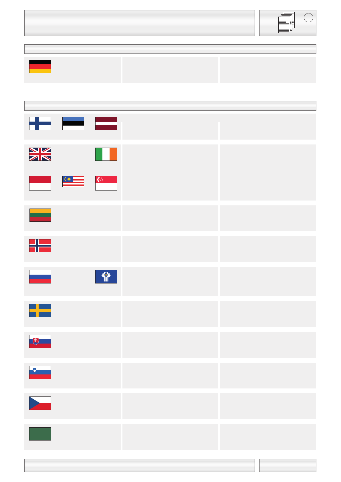
Germany
United Kingdom Ireland
Slovakia
Czech Republic
Slovenia
Sweden
Lithuania
Finland Estonia
Latvia
Indonesia Malaysia
Singapore
Norway
Russia CIS-States
Hungary
1
GB
 Loading...