

Page 1
AUTOMATIC
FOODSERVICE
EQUIPMENT
AUTOMATIC GAS BROILER
MODELS 980 GAS, 950 GAS AND 930 GAS
OWNER’S MANUAL
IMPORTANT: RETAIN THIS MANUAL IN A SAFE PLACE
FOR FUTURE REFERENCE.
Broiler area must be kept free of combustible materials, and the flow of combustion and ventilation air must not
be obstructed. Operating personnel must not perform any maintenance or repair functions. Contact your Nieco
Authorized Dealer.
In a prominent location, post instructions to be followed in the event the user smells gas. This information shall be
obtained by consulting your local gas supplier.
FOR YOUR SAFETY:
Do not store or use gasoline or other flammable vapors or liquids in
the vicinity of this or any other appliance.
WARNING: Improper installation, adjustment, alteration, maintenance
can cause property damage, injury, or death. Read the installation,
operating and maintenance instructions thoroughly before installing
or servicing this equipment.
Page 2

Page 3

3
TABLE OF CONTENTS
A. General Information.....................................................................................................................4
Description
B. Machine Installation.....................................................................................................................5
Pre-Installation
Mounting
Hood Requirements
Clearance
Gas Connection
Electrical Connection
Pre-Operation Check
Gas Connectors and Restraining Device
C. Operation ......................................................................................................................................8
Controls and Indicators
Gas System Controls
Step-by-Step Lighting Procedure
Shutdown Procedure
Automatic Temperature Control
Bun Platen Adjustment
D. Assembly/Disassembly and Cleaning........................................................................................11
E. Conveyor Belt Removal...............................................................................................................14
F. Conveyor Belt Tension................................................................................................................15
Broil Belt Problems
G. Parts and Location.......................................................................................................................16
Model 980
Model 950
Model 930
H. Trouble Shooting Guide ..............................................................................................................25
I. Specifications...............................................................................................................................27
J. Wiring Diagrams...........................................................................................................................30
Page 4
4
A. GENERAL INFORMATION
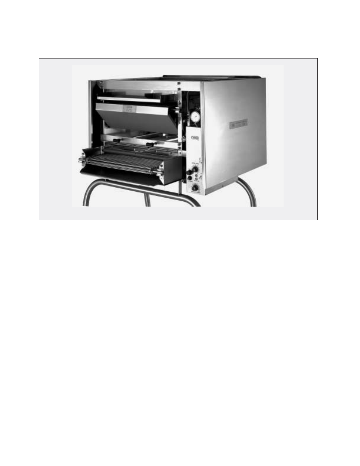
Model 980 Gas Model 950 Gas Model 930 Gas
DESCRIPTION
The Nieco Automatic Gas Broiler is a compact self-contained unit designed to broil hamburgers or other
food products by use of a conveyorized cooking section. In addition, these broilers are equipped with a
bun grilling section which caramelizes the buns to a golden brown.
The hamburgers and buns are loaded on the feed end of the broiler, pass between radiant gas burners or
an electrically heated bun platen, and come out the discharge end of the broiler. Flame broiling makes
the food taste great, and the unique Nieco system offers un-matchable product quality and consistency.
The Model 980 uses a total of 8 gas burners - 4 on top and 4 on the bottom. The Model 950 uses a total
of 6 gas burners - 3 on top and 3 on the bottom. The Model 930 uses 4 burners - 2 top and 2 bottom. All
three models utilize Nieco’s Automatic Temperature Control system, to assure proper cooking in periods
of high volume usage.
Page 5

5
B. INSTALLATION
PRE-INSTALLATION
Uncrate the broiler, and inspect for shipping damage. Contact the factory if there is obvious damage.
Remove the tape securing the machine parts, and install the parts in their proper location. Refer to the
Parts and Location section of this manual. If you find concealed damage to any part of this unit, contact
your freight carrier immediately. The factory warranty does not cover freight damage.
MOUNTING
If the broiler was shipped with a tubular stand, refer to separate tubular stand assembly instructions.
Note: The four legs of the broiler stand are equipped with casters. Always set the brakes on the
casters to prevent the broiler from shifting during operation or cleaning.
LEVELING
Make sure that the broiler is level. Factory stands are equipped with adjustable casters.
HOOD REQUIREMENTS
This appliance must be installed under a ventilation hood of adequate size and capacity:
Model CFM CMH
980 1100 1869
950 800 1360
930 600 1020
The hood should be at least 6" (152MM) larger in all dimensions than the appliance top, and be 12" to
18" (305MM - 457MM) above the top. Do not obstruct the flow of combustion and ventilation air. An adequate air supply must be available for safe and proper operation.
Note: See the National Fire Prevention Association booklet on ventilation of cooking equipment.
Write to: NFPA, 470 Atlantic Ave., Boston, MA 02210. Local codes on venting must also be complied with.
CLEARANCE
For proper installation, the minimum clearance from combustible and non-combustible construction is 6"
(152MM) from the back and 6" (152MM) from the front of the machine. Keep appliance area free from
combustibles.
To facilitate disassembly and service of the unit a minimum of 24" (610MM) should be allowed on the
control panel (right) side of the broiler, as well as in front of the broiler.
GAS CONNECTION
At rated BTU capacity, the gas supply should deliver a pressure of at least 6" water column at the broiler
connection for natural gas, and 11" water column for propane gas. Incoming gas supply pressure must
not exceed 14" water column for either type of gas.
The appliance was shipped from the factory ready for gas supply hook-up to the shutoff valve under the
broiler. For disconnect, a manual valve must be located in the gas supply line upstream from the connecter.
If the machine is installed on a moveable stand; (1) the installation shall be made with a connector that
complies with the Standard for Connectors for Moveable Gas Appliances, ANSI Z21.69-1987, and
Addenda, Z21.6a-1989, and a quick disconnect device that complies with the Standard for QuickDisconnect Devices for Use With Gas Fuel, ANSI Z21.41-1989, and (2) adequate means must be provided to limit the movement of the appliance without depending on the connector and the quick-disconnect
device or its associated piping to limit the appliance movement. (See figures on page 6.)
Note: Appliance installation must conform with all local codes, or in the absence of local codes,
with the National Fuel Gas Code ANSI Z223.1-1988. Check all fittings for gas leaks, including
Page 6

6
pilot tubing and inlet connections as soon as the appliance is connected to the gas supply.
Note: This appliance and its individual shutoff valve must be disconnected from the gas supply
piping system during any pressure testing of that system at test pressures in excess of 1/2 psig
(3.45 kPa).
Note: This appliance must be isolated from the gas supply piping system by closing its individual
manual shutoff valve during any pressure testing of the gas supply piping system at test pressures equal to or less than 1/2 psig (3.45 kPa).
In Canada, installation shall be in accordance with CAN/CGA-B149.1 Natural Gas or CAN/CGA-B149.2
Propane Gas, and local codes where applicable.
By public initiative, the State of California has adopted legislation (Proposition 65) which requires manufacturers of many types of products, including gas appliances, to warn consumers of their products that
contain chemicals or produce substances listed by the State of California to either cause cancer, birth
defects, or other reproductive harm.
WARNING: If not installed, operated, and maintained in accordance with the manufacturer's
instructions, this product could expose you to substances in fuel, or from fuel combustion which
can cause cancer, birth defects, or other reproductive harm.
ELECTRICAL CONNECTION
Power requirements are stated on the unit nameplate and must be connected accordingly. Before starting broiler, tighten all electrical connections in control box. An electrical diagram is located inside the control box.
Note: This appliance must be electrically grounded in accordance with local codes or in the
absence of local codes, the National Electrical Code, ANSI/NFPA No. 70-1990. In Canada, in
accordance with the Canadian Electrical Code CSA 22.1 part 1, or local codes.
WARNING: This appliance should be connected with a four-pronged grounding plug for
your protection against shock hazard. Be sure to plug directly into a properly grounded
four-prong receptacle. Do not cut or remove grounding prong from plug.
Note:
This appliance cannot be safely operated in the event of a power failure. No attempt
should be made to operate during a power failure. Disconnect power supply before servicing.
PRE-OPERATION CHECK
Be sure that all parts are installed in the proper location. Refer to OPERATION section for lighting procedure. Start broiler and test for proper operation.
Page 7
7
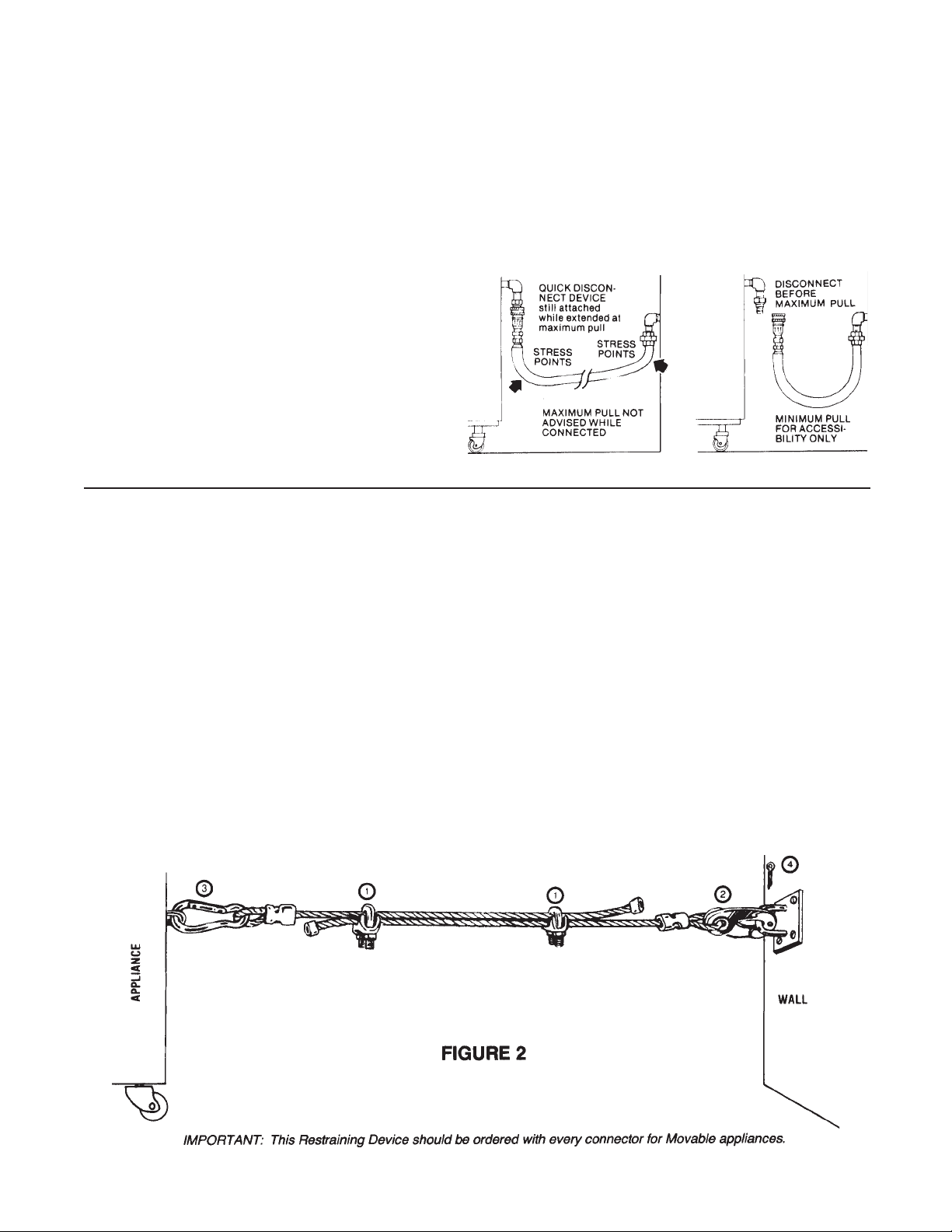
INSTALLING GAS APPLIANCE CONNECTORS
AND FLEXIBLE GAS LINES CORRECTLY
RESTRAINING DEVICE
INSTALLATION AND USE
This high strength restrainer is to be used with all moveable (castered) appliances. It fully complies with
American Gas Association requirements. References: Z21.69, Z83.11, and Z21.41 with current revisions.
Installation is quick and positive. In Canada, device is in accordance with CAN 1-6.9-M70 Quick
Disconnect Devices for use with gas fuel, and CAN 1-6.10-88 metal connectors for gas appliances.
Correct length for any appliance is simply a matter of loosening two adjuster clips (1) and re-tightening.
(3" to 6" shorter than appliance connector is desired length.)
Restrainer is made of heavy duty steel cable, with a strong scissor hood (2) at one end, and an equally
strong spring hook (3) at the other. Cotter pin (4) is supplied to secure the installation.
For safety in the kitchen area, and to insure maximum service life, it is vitally important to correctly
install connectors.
In order to avoid sharp kinks or excessive bends
that could have a damaging effect on the connector, it may be necessary to attach pipe elbows in
order to bring the connector into its proper plane.
For easy movement of the appliance, the connector should be installed with a "lazy" loop for minimum tension.
Note: Gas appliances should be disconnected
prior to maximum movement. (Minimal movement is possible to connect hose.)
WRONG
Avoid sharp bends and
kinks when pulling equipment away from wall.
RIGHT
Minimum pull of equipment is permissible for
accessibility to quick disconnect device.
Page 8
8
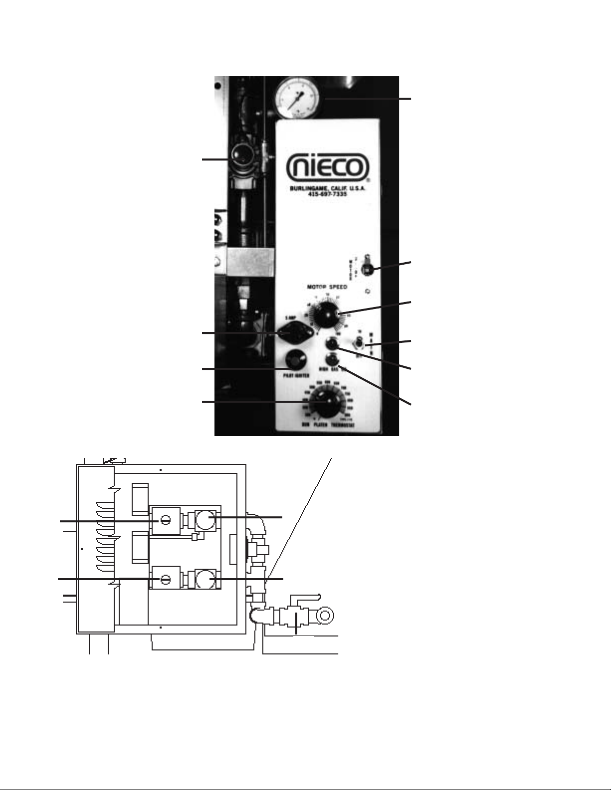
GAS SYSTEM CONTROLS
1. Main Gas Pressure Regulator.
Controls the gas pressure when the
High Gas is off.
2. High Gas Pressure Regulator.
Controls the gas pressure in High Gas mode.
3. Main Gas Solenoid Valve.
4. High Gas Solenoid Valve.
5. Manual Gas Valve.
Valve is open when in line with pipe.
1
2
3
4
5
Gas Safety Valve
(red push button)
5 Amp Fuse
Pilot Ignitor
(red)
Bun Platen Thermostat
Gas Gauge
Recommended Settings:
Natural Gas - 3” Low, 5” High
Propane - 8” Low, 11” High
Motor Breaker Switch
Motor Speed Control
Main On/Off Switch
Power On Indicator Lamp
(red)
High Gas Indicator Lamp
(amber)
C. OPERATION
Controls and Indicators
WARNING: Use extreme caution when making adjustments to the gas pressure regulator. Only
authorized personnel should open the control box.
Page 9
9
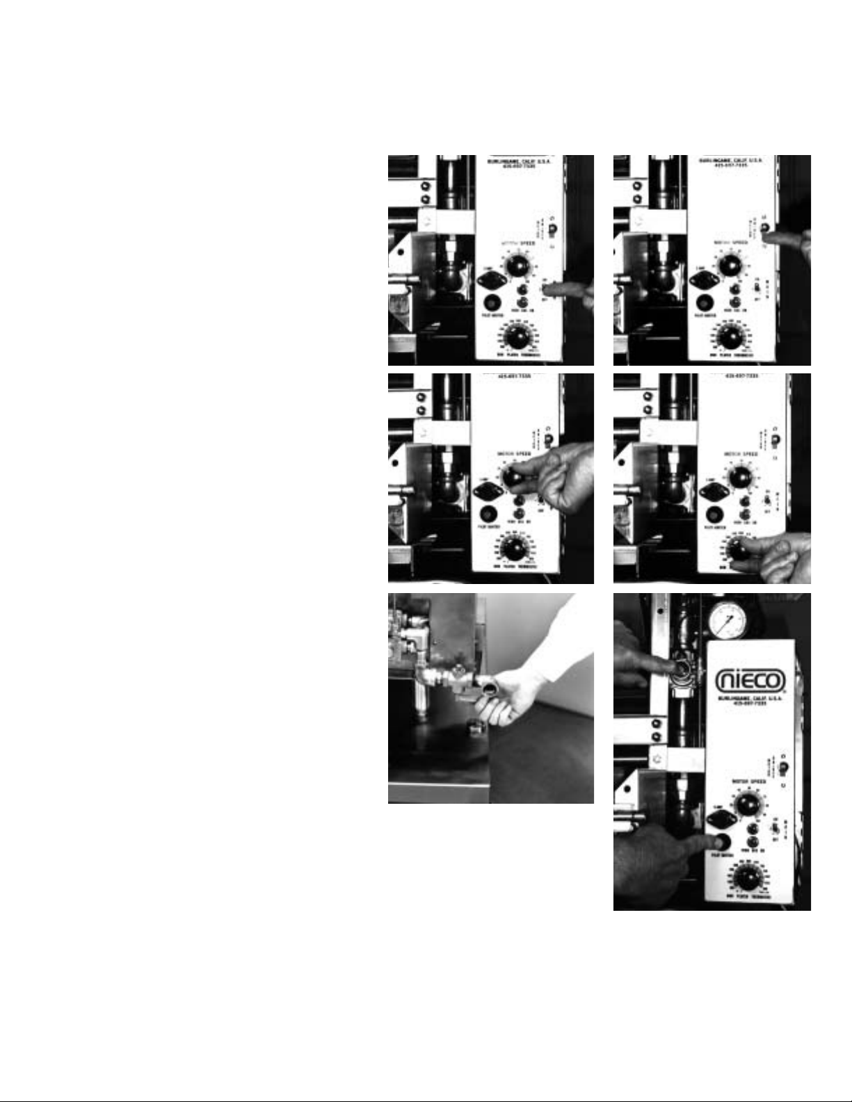
STEP-BY-STEP LIGHTING PROCEDURE
Before lighting, make sure that all parts are installed in the proper location, all controls are turned off,
and the ventilation hood fan is turned on.
1. Turn on Main Power Switch. 1 2
2. Turn on Motor Switch.
3. Set Motor Speed Control knob to 3 4
desired setting. (BK Spec = 26 Links per
Minute).
4. Set the Bun Platen Thermostat to
the desired setting. (Use a setting of
450° F to start.)
5. Open the Manual Gas Valve. The valve is 5 6
open when the handle is in-line with the pipe.
6. Push and hold the Red Push Button Valve.
This will start the flow of gas to the pilot lights.
While holding in the Red Button, push the Ignitor
button on the front of the control box. After the
pilot lights, hold the Red Valve in for 30 seconds
to allow the thermocouple to heat. When you
release the Red Push Button, the burners
should ignite.
If the ignitor is not working, use a long-stem
lighter to manually light the pilot.
7. After lighting the broiler, check the gas pressure
to be sure it is adjusted to the levels stated on the
machine rating plate. Allow the broiler at least
30 minutes to warm up.
SHUTDOWN PROCEDURE
For EMERGENCY shutdown, turn off the Main Power switch and shut off the manual gas valve.
For PLANNED shutdowns - clear machine of all food products, turn the motor and main switches off.
CAUTION: Turn all appliance switches off before disconnecting cord from power supply.
Page 10

10
AUTOMATIC TEMPERATURE CONTROL (ATC)
The Nieco Automatic Temperature Control (ATC) is a system that operates the broiler at two different
energy input rates; a high energy input for initial warm-up and periods of high volume, and low energy for
regular operation. This dual input rate and the ATC allow the broiler to operate at a very consistent temperature throughout the day and thus provide a very consistently broiled product. Since the broiler will
remain on the lower input rate (low gas) most of the day, a substantial energy savings is realized.
The ATC consists of two gas pressure regulators piped in parallel, a solenoid valve in series with the high
gas pressure regulator, a probe to sense the temperature at the loading end of the broiler, and a control
unit which is operated by the signals from the probe. The control unit causes the solenoid valve to open
and close. When the valve is open, the machine is in high gas mode, and the gas pressure is increased
to heat up the broiler.
Under heavy product loads, the temperature sensed by the ATC probe will drop low enough to cause the
ATC to open the solenoid valve. When the solenoid valve opens, the amber indicator light on the control
panel will light. The ATC will keep the broiler on high pressure until the temperature sensed by the probe
returns to the calibrated setting.
CALIBRATING THE ATC
1. Loosen the control knob lock screw and set the ATC control knob to 600° F.
2. Turn on the Main Power Switch.
3. Turn on the Motor Power Switch.
4. Light the broiler following the procedure in this manual.
5. The broiler should be in high gas mode at this time. (Amber light on.)
6. When the broiler reaches 600°, the high gas will shut off, and the broiler will be in low gas.
7. 30 minutes after lighting the broiler,
slowly turn the ATC control knob up (clockwise) until
the high gas clicks on. This is the idle temperature of the broiler.
8. As soon as the high gas turns on (there will be an audible “click”), slowly turn the ATC
down (counter clockwise) 10° to 20° below the point where the high gas clicks on.
9. The control knob setting may need a minor adjustment on the first day of use, in order to
maintain 10° to 20° below the normal idle temperature. Once the adjustment is correct, it
need not change from day to day unless the broiler operating conditions change.
10. After all adjustments have been made, tighten the control knob lock screw to prevent accidental movement.
WARNING
Never set the ATC control knob at a setting high enough to keep the broiler continuously in high gas
pressure. The machine may be damaged, energy costs will be much higher, and some broiler parts may
wear out prematurely.
BUN GRILLING PLATEN
The 980, 950 and 930 are equipped with independently adjustable dual bun grilling platens. The clearance of each platen is adjusted by turning the black handles located directly above the platens, at the
feed end of the machine. Frequent adjustment should not be necessary.
FOOD PREPARATION, COOKING, AND HANDLING PRACTICES
Established guidelines for safe food preparation, cooking, and handling should be adhered to rigidly. The
Nieco Automatic Broiler is very consistent in cooking. Check the temperature of the meat cooked frequently to assure that the broiler is set up properly.
Page 11
11
D. ASSEMBLY/DISASSEMBLY AND CLEANING
If this appliance is connected to the gas supply by a flexible gas line and quick disconnect coupling, it must also be connected to a restraining device (see installation instructions). If the appliance is moved and then returned to its original
position, it must be reconnected to the restraining device and the casters locked before resuming operation.
1. Clear machine of all food products. Allow the machine to run empty for ten minutes in order to burn off the residue on
the belt. Turn Main Power and Motor switches off. Allow the machine to cool before you disassemble.
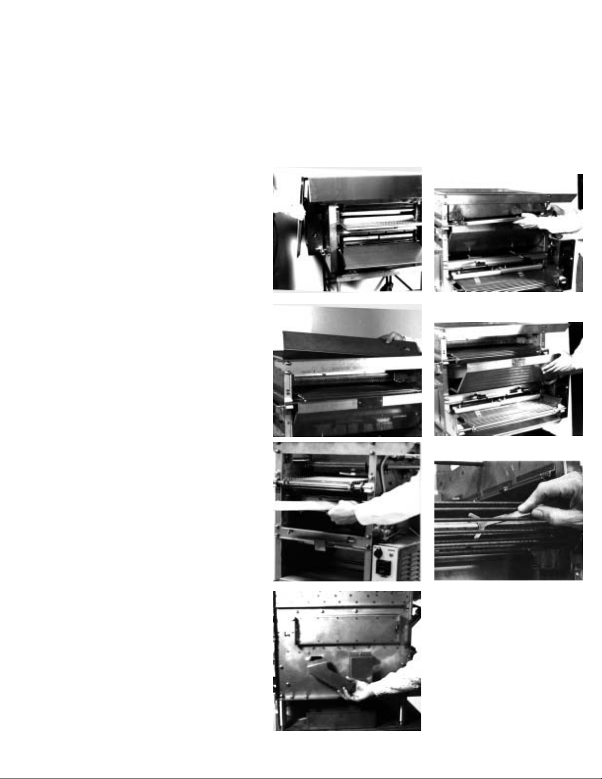
2. Remove the Side Panels by 2 3
lifting up and off. Wipe clean
with a degreaser.
FROM THE FRONT OF THE BROILER
3. Remove the Patty Feeder by
lifting up and out. Clean daily
using soap and water.
4. Remove the Upper Burner 4 5
Front Reflector, and clean
with soap and water.
5. Remove the Grease Pan by sliding
it out the front. Clean daily using
soap and water.
6. Remove the Belt Scraper. Notice 6 7
the position it sits in before
removing, so that you can replace
it properly. Clean daily using soap
and water or degreaser.
7. Scrape the shafts with the special
tool provided, or with a flat head
screwdriver.
FROM THE LEFT SIDE OF THE BROILER
8. Remove the Grease Chute and 8
Grease Box, and clean using
soap and water.
Page 12
12
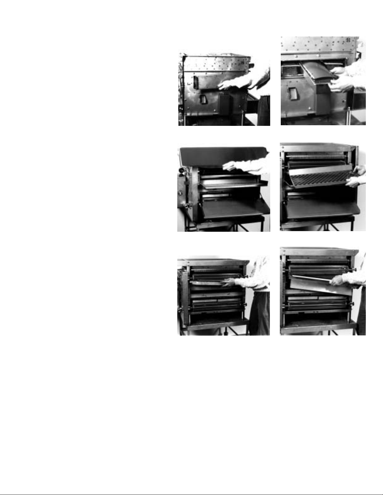
9. Remove the Burner Access Cover. 9 10
10. Slide the Lower Burners out and
remove the Protective Shields.
Clean the shields by scraping off
any built up residue, then soak in
soap and water.
Clean the shields
daily. This will help to prolong
the life of the burner and keep
the broiler cooking properly.
FROM THE BACK OF THE BROILER
11. Remove the awning by lifting up 11 12
and off. Clean using soap and
water.
12. Remove the Patty Discharge Pan and
Insert. Clean daily using hot soapy water,
and sanitize.
13. Remove the Stripper Blade. 13 14
Scrape any built up residue
from the blade. Clean by soaking
in soap and water. Sanitize.
14. Remove the Lower Burner
Reflector. Notice the position
of the piece before removing it,
so that you can re-install it
properly. Clean by soaking
in soap and water.
Page 13
13
WEEKLY CLEANING
In addition to the daily cleaning, perform these
steps on a weekly basis.
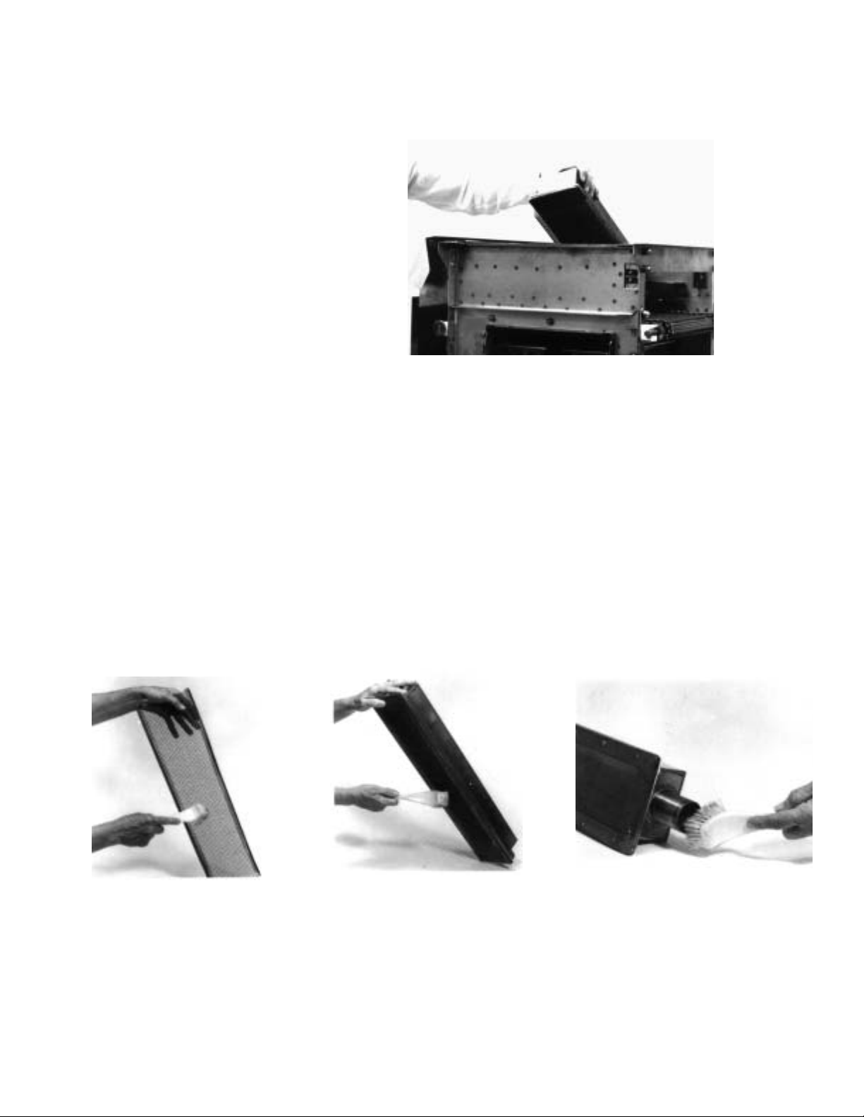
1. Remove the Upper Burners 1
and clean as following the steps outlined
below (see A,B & C).
2. Clean all Pilot Burners and Main Burner
Orifices with rubbing alcohol and a
pipe cleaner.
3. Remove all grease and carbonized build-up
from the interior of the broiler. Do not spray
anything (i.e. oven cleaner) inside the broiler.
REPLACE REVERBERATOR AT
THE FIRST SIGN OF BREAKAGE.
A. Remove Reverberator and clean
with a stiff bristle brush.
DO NOT SOAK OR SUBMERGE THE BURNERS IN WATER. WATER CAN CAUSE IMPROPER BURNER
PERFORMANCE.
B. Clean Burner Screen with a stiff
bristle brush.
HOLD BURNER WITH THE SCREEN
FACING DOWN WHILE BRUSHING.
This prevents particles from dropping
down and lodging inside the burner.
C. Clean Burner Venturi with a stiff
bristle brush.
HOLD BURNERS SO THAT PARTICLES WILL NOT DROP INSIDE.
Page 14
14
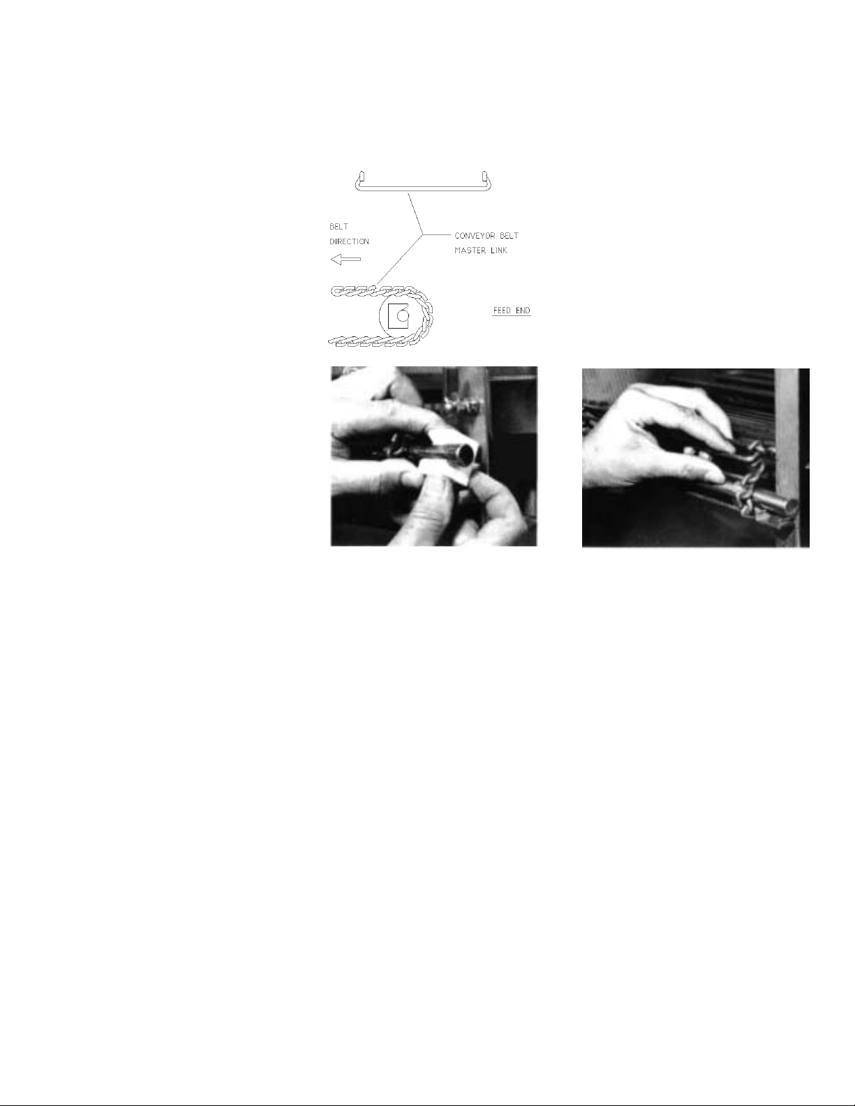
E. CONVEYOR BELT REMOVAL
Before beginning, notice the way the belt runs through the broiler. Also notice the direction the knuckles face. Be sure to
re-assemble in the same way.
1. Run belt until the Master Link is 1
near the front idler shaft.
2. Lift shaft and Teflon Blocks up, 2 3
and slide the blocks out.
3. Unhook the Master Link.
To reassemble, reverse the procedure. Be sure to reassemble the belt with the knuckle opening facing away from the
direction of travel.
Page 15
15
F. CONVEYOR BELT TENSION
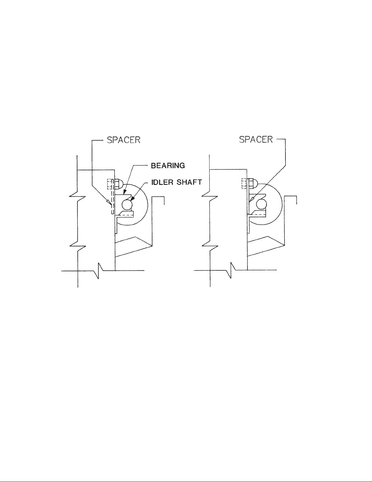
Maintain proper tension on the conveyor belts to prevent jamming. Bearing spacers (pictured below) are
supplied with the broiler to make minor tension adjustments. Major tension adjustments are made by
removing a link or links from the belt.
The diagram on the left shows the spacer in the stored position. The diagram on the right shows the
spacer behind the teflon bearing tightening the belts.
Belt tension should be checked monthly. To do this, allow the machine to cool, then grip the idler shaft at
each end and pull on it. If the shaft and bearings move 3/16” or more, the spacers should be placed
behind the bearings to tighten the belts. If the spacers are already behind the bearings, return them to
the stored position and remove a link from the conveyor belt.
BROIL BELT PROBLEMS
Interference with stripper blade:
The most common belt problem to be expected is the physical interference of the belt with the stripper
blade. This is caused by bent or warped rods on the meat belt, and can be fixed by replacing the rods
that are causing the problem. Other causes are bent stripper blades, or utensils jammed in the belt.
Blocked belts:
When trouble shooting drive problems, it is important to ensure that the belt is not being blocked. To do
this, detach the drive chain and turn the meat belt by hand. The belt, with the motor detached, should
turn freely and easily. If the blockage has occurred which is preventing the belt from turning, the blockage should be removed before the drive chain is re-attached. The drive chain can be easily removed
from the drive sprocket (on the motor shaft) by loosening the mounting bolts and raising the motor.
Page 16
16
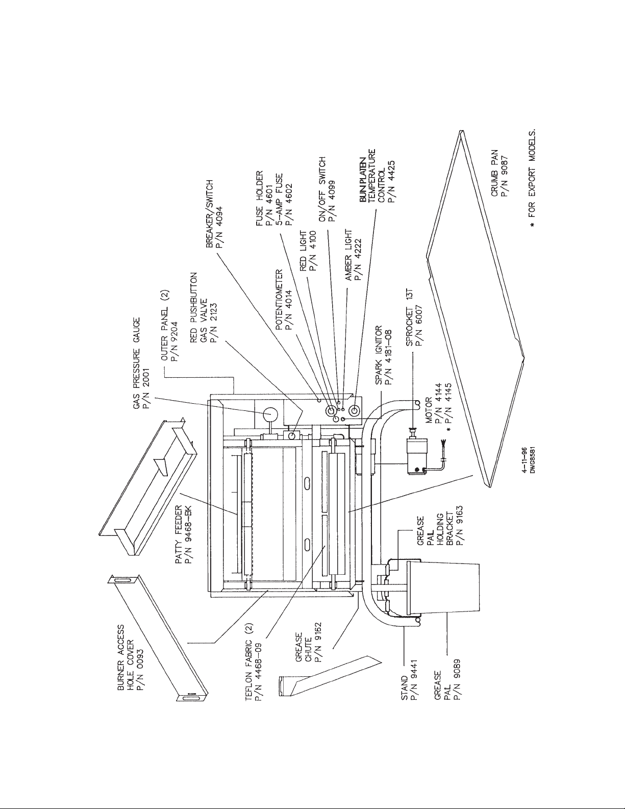
G. PARTS AND LOCATION
Model 980 Gas - Feed End View
Page 17
17
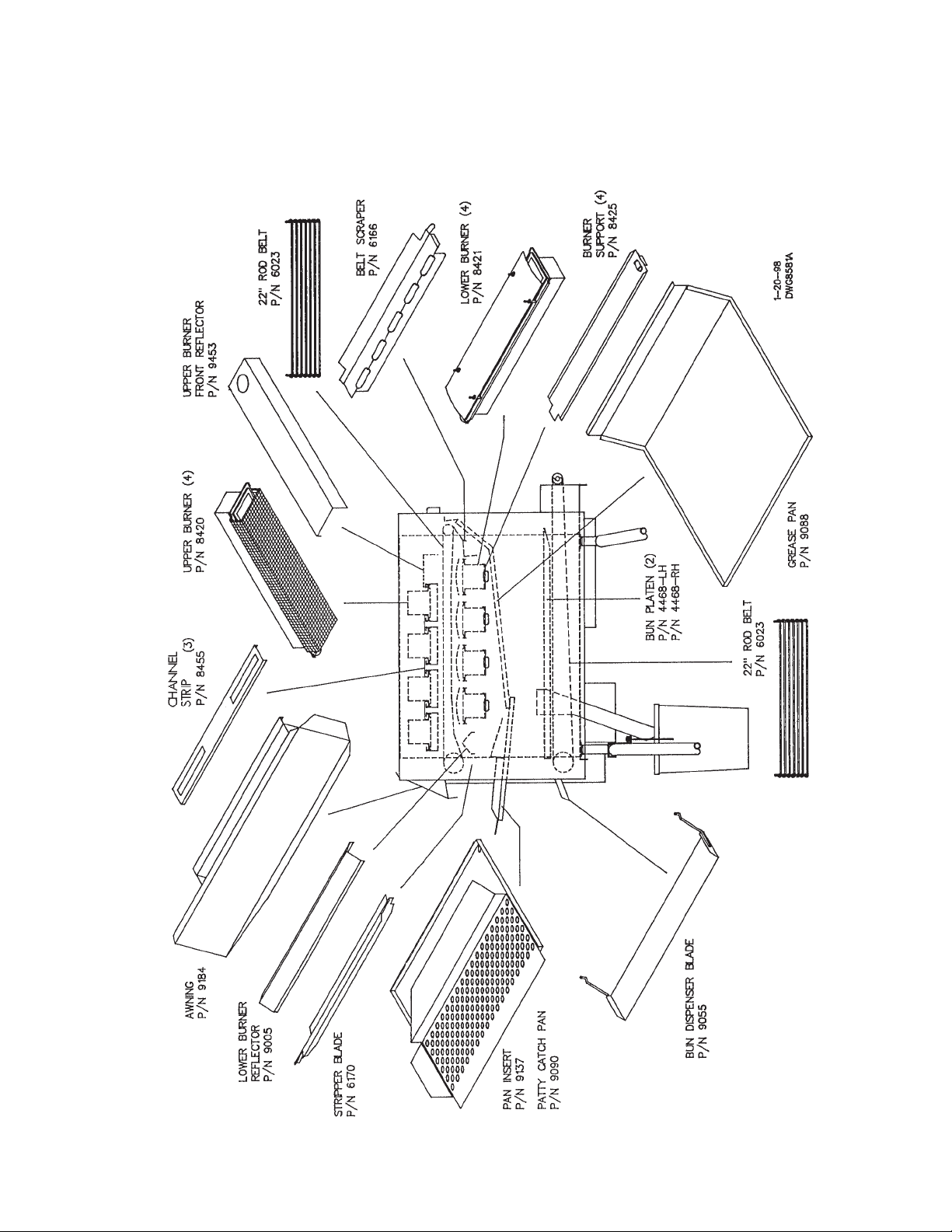
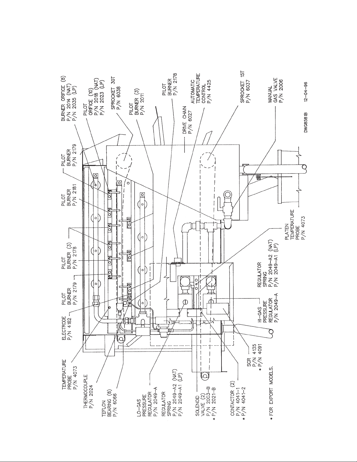
G. PARTS AND LOCATION
Model 980 Gas - Left Side View
Page 18
18
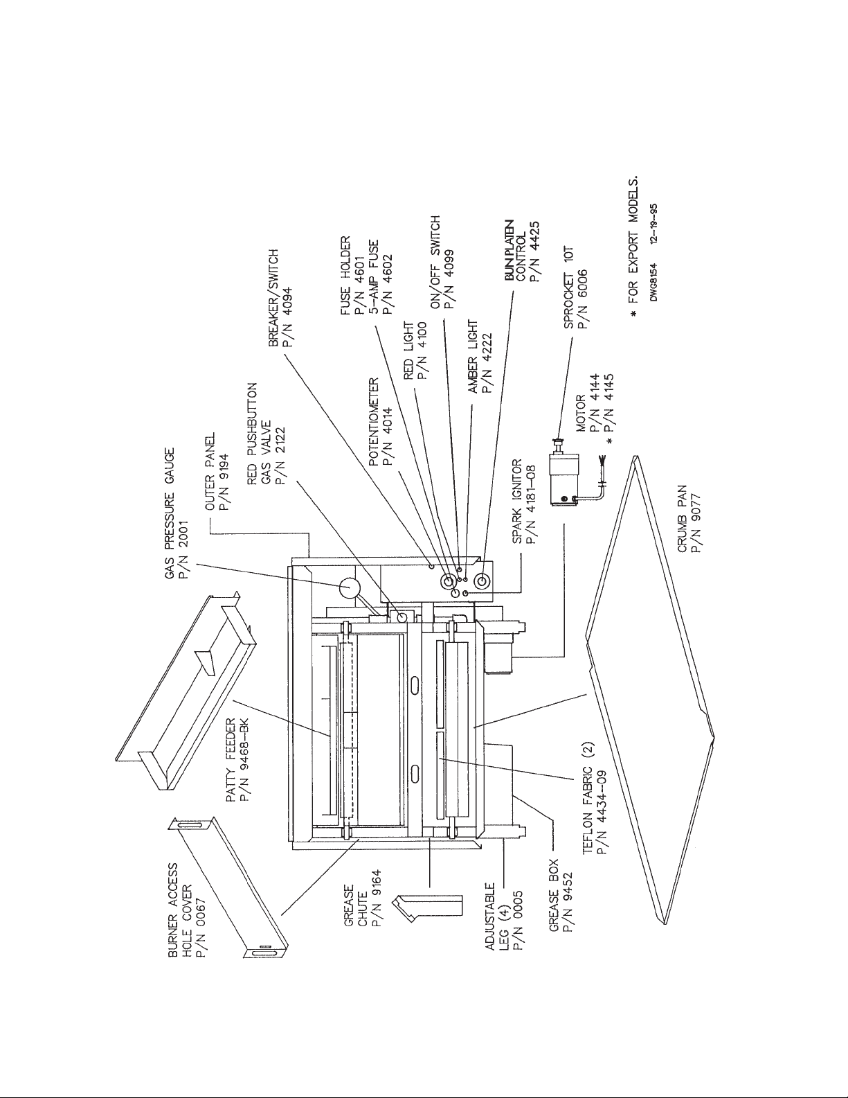
G. PARTS AND LOCATION
Model 980 Gas - Right Side View
Page 19
19
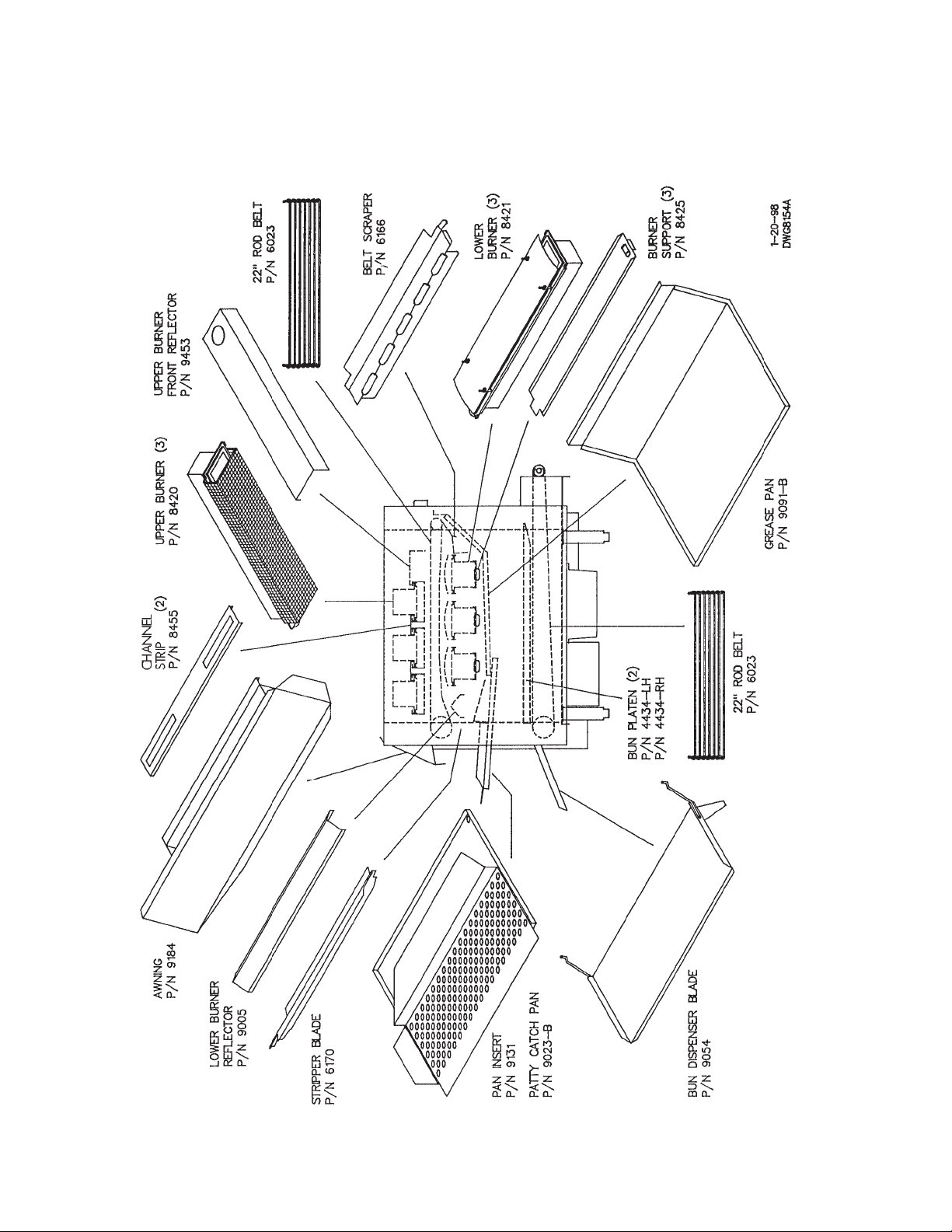
G. PARTS AND LOCATION
Model 950 Gas - Feed End View
Page 20
20
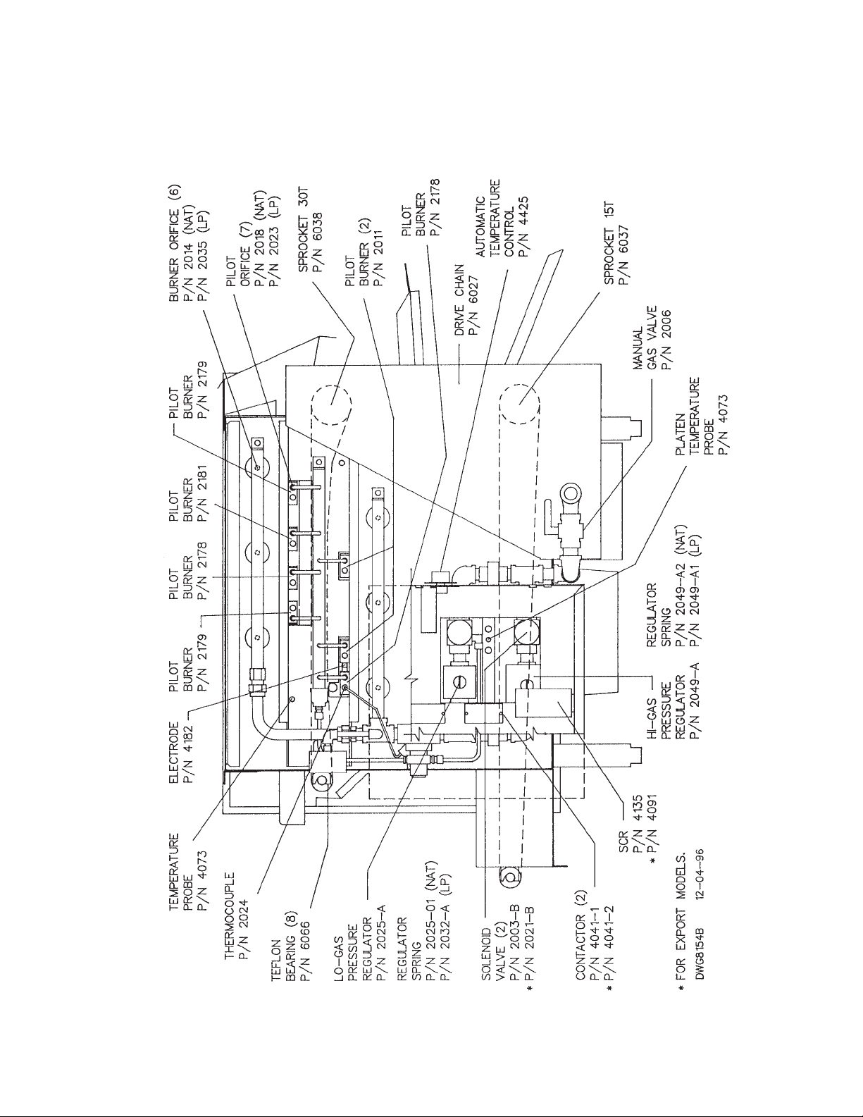
G. PARTS AND LOCATION
Model 950 Gas - Left Side View
Page 21
21
G. PARTS AND LOCATION
Model 950 Gas - Right Side View
Page 22
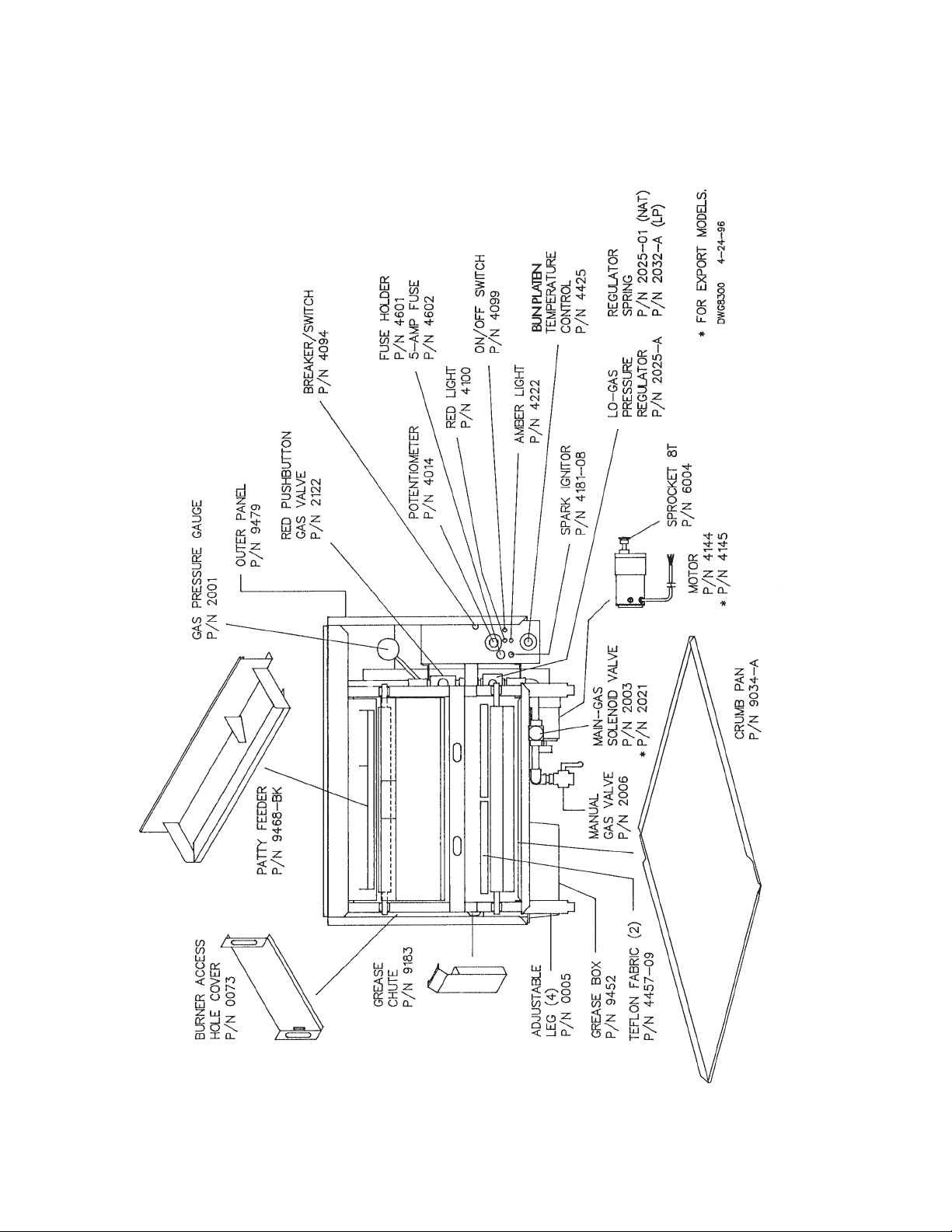
22
G. PARTS AND LOCATION
Model 930 Gas - Feed End View
Page 23
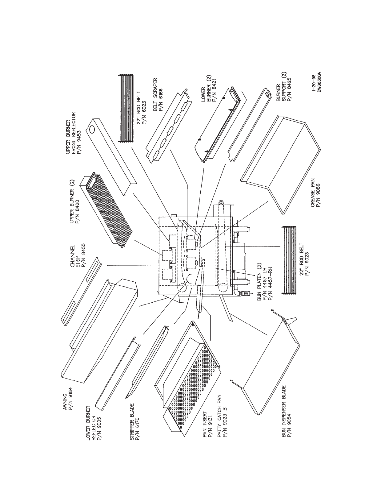
23
G. PARTS AND LOCATION
Model 930 Gas -Left Side View
Page 24
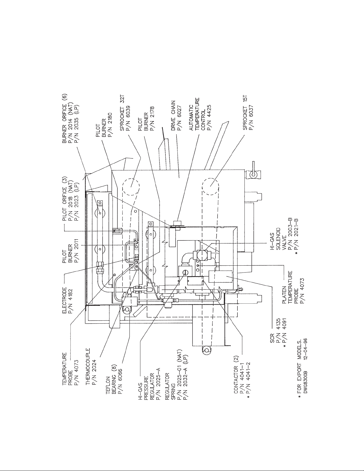
24
G. PARTS AND LOCATION
Model 930 Gas - Right Side View
Page 25

25
H. Troubleshooting Guide
PROBLEM PROBABLE CAUSES SOLUTION
Pilot Burners won't light.
Pilots won't stay lit when push button
is released.
Pilot flame weak or yellow.
Main Burners won't light, or they go
out during operation.
Burner appears dim (cooler).
Burners backfire or sputter.
Conveyor belts won't advance.
1. Pilot Burner dirty, or orifice plugged.
2. Push button valve not fully depressed.
3. Air in pilot line.
4. Electric spark ignitor dislocated.
5. Electric power not on, or machine not
plugged in.
6. Gas not hooked up or on.
1. Thermocouple not hot yet.
2. Weak pilot flame.
3. Thermocouple dirty or defective.
4. Push button power unit defective.
1. Dirty pilot or orifice.
2. Pilot tubing plugged or pinched off.
3. Incoming gas pressure too low.
1. Pilot flame too small.
2. Air draft blowing pilot flame out.
3. Electrical supply interruption.
1. Burner orifices dirty.
2. Gas pressure too low.
3. Gas line partially blocked.
4. Pressure regulator defective.
5. Burners not installed properly.
6. Burner venturi dirty.
7. Main gas valve partially closed.
8. Burner distributor screen dirty.
1. Gas pressure too high.
2. Burners have gotten wet.
3. Burner venturi dirty.
1. Machine not plugged in.
2. Wall circuit breaker off.
3. Motor control switch off.
4. Motor speed control not set properly.
5. Speed control pot. or SCR defective.
6. Drive chain broken.
7. Gear motor defective.
8. Loose or broken wire.
9. Motor unplugged.
10. Drive sprocket loose.
1. Clean pilot burner, replace orifice.
2. Repeat start-up procedure.
3. Purge line by holding down red push
button before igniting.
4. Position white electrode so the tip is
1/4" from the pilot burner, or light
manually.
5. Plug in/turn on.
6. Check Gas Supply
1. Repeat starting procedure, and hold
the push button in longer.
2. See Below.
3. Clean or replace.
4. Replace.
1. Clean or replace.
2. Check line. Pilot tubing can be
removed with a wrench.
3. Adjust pressure regulator.
1. Replace pilot orifice. See Above.
2. Check for drafts.
3. Secure power supply.
1. Clean or replace.
2. Adjust pressure regulator.
3. Check line and clear.
4. Replace.
5. Remove and install properly.
6. Clean. See Cleaning Instructions.
7. Open fully so that handle is in line
with the valve.
8. Clean.
1. Adjust pressure regulator.
2. Dry thoroughly, replace gasket.
3. Clean.
1. Plug in.
2. Turn on.
3. Turn on.
4. Reset cook time.
5. Replace.
6. Replace or repair.
7. Replace.
8. Tighten or replace.
9. Plug in.
10. Tighten sprocket set screw.
Page 26

26
PROBLEM PROBABLE CAUSES SOLUTION
Motor control switch trips.
Conveyor belt speeds are erratic.
Broiled product over or under
cooked.
Bun Platen won’t heat.
Bun platen gets warm but not hot..
Bun platen gets too hot.
Hamburger patties stick to belt.
1. Conveyor belt jammed
2. Switch defective.
3. Drive chain binding.
4. Shorted wire to motor.
5. Gear motor defective.
1. Drive chain binding.
2. Gear motor defective.
3. Loose drive sprockets.
1. Wrong conveyor belt speed.
2. Product temperature not consistent.
1. Wall circuit breaker off.
2. Main power switch off.
3. Defective thermostat.
4. Defective platen contactor.
5. Loose or broken wire.
6. Machine not plugged in.
7. Thermostat turned off.
8. Inadequate voltage.
1. Thermostat setting too low.
2. Thermostat defective.
3. Platen defective.
4. Power cord not fully plugged in.
1. Thermostat setting too high.
2. Sensing bulb not fully inserted into
platen.
3. Thermostat defective.
4. Water in control.
1. Stripper blades not adjusted properly.
2. Product under broiled.
3. Product too lean.
4. Product too thin.
5. Burners not hot enough.
6. Heat reflectors not installed, or
installed improperly.
7. Patty feeder adjusted too low.
8. Patty belt too tight.
9. Warped links in the patty belt.
1. Remove jam, reset switch.
2. Replace.
3. Adjust tension of chain.
4. Repair wire.
5. Replace.
1. Adjust tension of chain.
2. Replace.
3. Tighten set screws.
1. Reset cook time.
2. Be sure refrigerators and freezers
are working and that product temperature is consistent.
1. Turn on.
2. Turn on.
3. Replace.
4. Replace.
5. Tighten or repair.
6. Plug in.
7. Turn on.
8. Check power supply.
1. Increase setting.
2. Replace.
3. Replace.
4. Plug in and twist.
1. Decrease setting.
2. Insert bulb fully into platen. Bulb is
located on the control box side of the
platen.
3. Replace.
4. Allow to dry then cycle off and on.
1. Adjust.
2. Slow belt speed.
3. Check meat - 23% fat, scored both
sides.
4. Try thicker patties.
5. Check burners, see above.
6. Be sure all reflectors are installed
properly. Refer to parts and location
section.
7. Raise by moving the hanging bolts
up.
8. Loosen tension.
9. Replace warped links.
Page 27
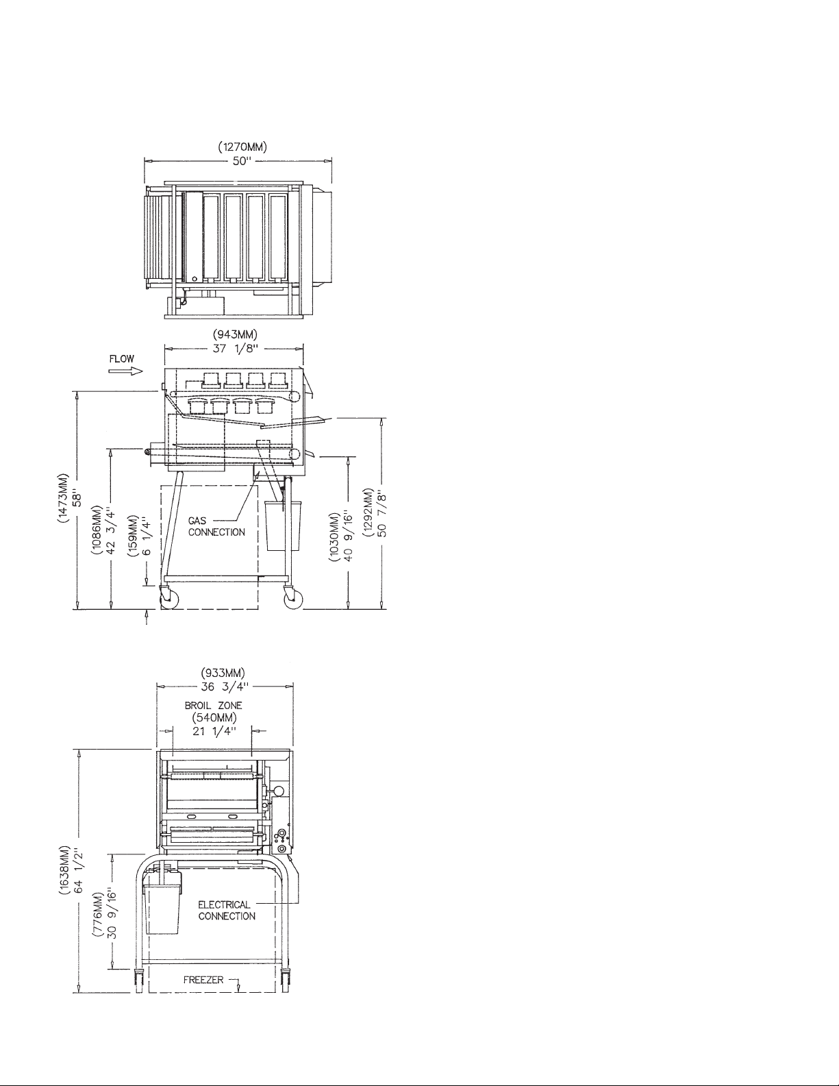
27
I. SPECIFICATIONS
Model 980
Weight LB KG
APPROXIMATE 545 247
SHIPPING 715 324
Exhaust CFM CMH
TYPICAL 1100 1869
Dimensions INCH MM
LENGTH 50 1270
HEIGHT 64 1⁄2 1638
W
IDTH 36
3
⁄4 933
Energy - Gas Model
GAS CONNECTION 3/4" N.P.T.
ELECTRICAL CONNECTION 208-240V/120V 1Ø
(SPECIFY EXACT VOLTAGE) 50/60 HZ 21A
A
VG. KW/HR 2.2
NATURAL GAS 3" W.C. 5" W.C.
BTU/HR 106,000 - 132,000
KCAL/
HR 26,173 - 32,593
PROPANE 8" W.C. 11" W.C.
BTU/
HR 106,000 - 132,000
KCAL/HR 26,173 - 32,593
Page 28
28
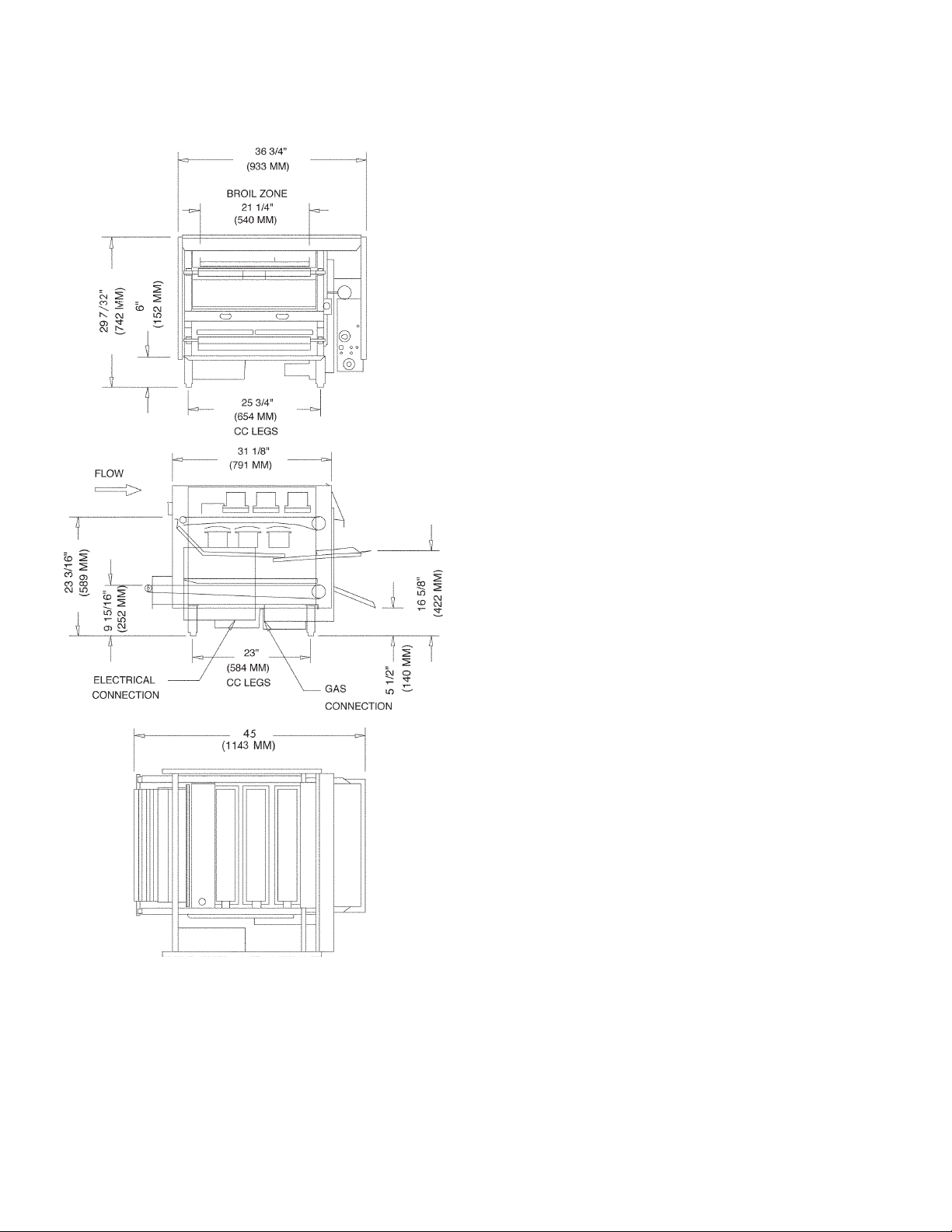
I. SPECIFICATIONS
Model 950
Weight LB KG
APPROXIMATE 495 225
SHIPPING 535 243
Exhaust CFM CMH
TYPICAL 800 1360
Dimensions INCH MM
LENGTH 45 1143
HEIGHT 29 7⁄32 742
W
IDTH 36
3
⁄4 933
Energy - Gas Model
GAS CONNECTION 3/4" N.P.T.
ELECTRICAL CONNECTION 208-240V/120V 1Ø
(SPECIFY EXACT VOLTAGE) 50/60 HZ 18A
A
VG. KW/HR 1.9
NATURAL GAS 3" W.C. 5" W.C.
BTU/HR 75,000 - 96,000
KCAL/
HR 18,900 - 24,192
PROPANE 8" W.C. 11" W.C.
BTU/
HR 75,000 - 96,000
KCAL/HR 18,900 - 24,192
Page 29
29
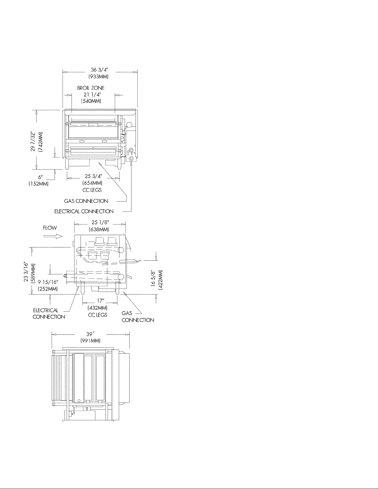
Model 930 Gas
Weight LB KG
APPROXIMATE 395 179
Exhaust CFM CMH
TYPICAL 600 1020
Dimensions INCH MM
LENGTH 39 991
HEIGHT 29 7⁄32 742
WIDTH 36 3⁄4 933
Energy - Gas Model
GAS CONNECTION 1/2" N.P.T.
E
LECTRICAL CONNECTION 208-240V/120V 1Ø
(SPECIFY EXACT VOLTAGE) 50/60 HZ 13A
AVG. KW/HR 1.4
N
ATURAL GAS 3" W.C. 5" W.C.
BTU/HR 54,000 - 70,000
KCAL/HR 12,350 - 15,880
P
ROPANE 8" W.C. 11" W.C.
BTU/HR 54,000 - 70,000
KCAL/
HR 13,608 - 17,640
Page 30
30
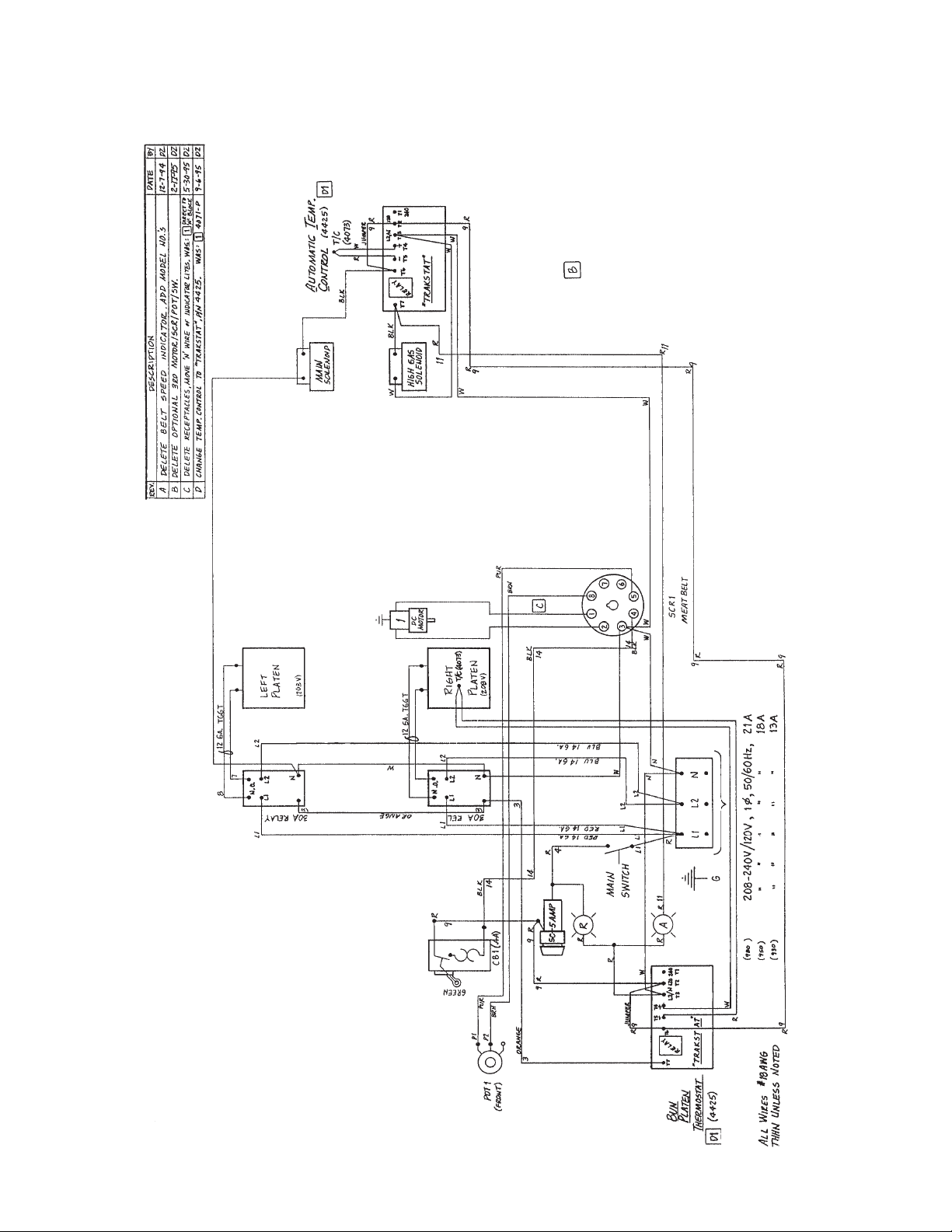
J. WIRING DIAGRAM
930, 950, 980 Gas - Domestic U.S.A.
Page 31
31
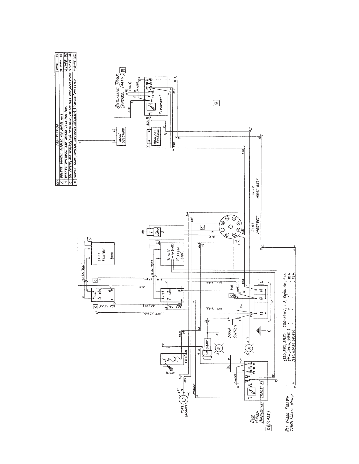
J. WIRING DIAGRAM
930, 950, 980 Gas - Export
Page 32

Nieco Corporation • 15 Guittard Rd. • Burlingame, CA 94010 • (650) 697-7335 • Fax (650) 697-3014
 Loading...