

Page 1
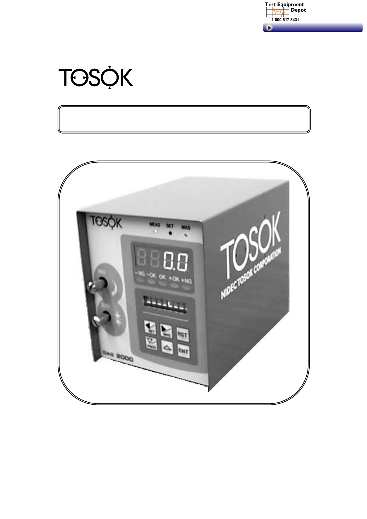
DIGITAL AIR MICROMETER
DIGITAL AIR MICROMETER
DAG2000 USERS MANUAL
99 Washington Street
Melrose, MA 02176
Phone 781-665-1400
Toll Free 1-800-517-8431
Visit us at www.TestEquipmentDepot.com
Second Edition 2002.10.25
NIDEC TOSOK CORPORATION
1
Page 2

DIGITAL AIR MICROMETER USERS MANUAL (Second Edition)
■ REQUEST DURING USE
In order to use this product safely, please follow the items below:
[Danger]
(1) The inside of this product has hundreds of volts of electric voltage.
During installation, transfer, maintenance, and inspection of this product or connections, please shut
down all the power and remove from the product the power and connection cables first.
(2) Standard attached power cable is for 100V. When using power voltage exceeding 125V, please prepare
separate 250V cable.
(3) Please do not trample or pull the connection cables that will be used for connecting the power cable to
the equipment.
Also, when removing power cable or connection cables, please be sure to hold the plug part. There is
danger of damage to the cable. By any means please do not use damaged power cables or connection
cables. This is a high voltage object and there is danger of electrical shock.
(4) Please make sure to install ground.
There is danger of electric shock during breakdown or short circuit.
[Warning]
(1) This product is a precise measuring device that performs measurement through air. For the air supply,
please prepare pure air with dirt, moisture and oils removed.
(2) Please make sure not to put foreign materials through the gaps of this product or the connecting
machines.
There is danger of incurring serious injury from electric shock, fire and breakdown.
[On bringing to overseas]
When bringing this product overseas, please confirm beforehand since there are various restrictions.
Please understand beforehand that when this product is brought overseas and accidents occur, this
company will be held responsible.
[About this manual]
(1) This manual was created doubly sure but if by chance suspicious points, omissions and such are noticed,
please inquire with our sales department.
(2) Diversion or reproduction of all or part of the contents without permission is not allowed.
(3) For purposes of improvements, changes can be made to product specifications, contents of the manual,
and appearance without notice in the future.
[About the warranty]
Warranty will be in accordance with the warranty regulations of this company
(1) Even during warranty period, expenses required for repairs will be charged if breakdown and damages
are caused by mishandling by the customer.
(2) There may be cases also when repairs for alteration made by customers cannot be accepted.
(3) Claims repair is standard. For business trip repairs, separate business trip expenses will be charged
even during warranty period.
2
Page 3

DIGITAL AIR MICROMETER USERS MANUAL (Second Edition)
TABLE OF CONTENTS
CHAPTER 1 INTRODUCTION------------------------------------------------------------------------------------- 1
1.1 Outline -------------------------------------------------------1
1.2 Merits ------------------------------------------------------ 1
1.3 Block Diagram ------------------------------------------------------ 2
CHAPTER 2 NAME AND FUNCTION OF EACH PART------------------------------------------------------ 3
CHAPTER 3 PROCEDURE UP TO MEASUREMENT--------------------------------------------------------- 4
3.1 For normal cases ------------------------------------------------------- 4
3.2 For work tolerance (judgment limits) change cases ------------------------------------------------------- 5
3.3 For first time measurement tool connection cases ------------------------------------------------------ 6
3.4 For several measurement tools connection cases ------------------------------------------------------- 7
CHAPTER 4 MASTER CALIBRATION -------------------------------------------------------------------------- 8
4.1 Master calibration by 2 masters ------------------------------------------------------ 8
4.2 Master calibration by 1 master -----------------------------------------------------10
4.3 Clearing of master data ------------------------------------------------- ------11
4.4 Master calibration error -------------------------------------------------------11
CHAPTER 5 MEASUREMENT------------------------------------------------------------------------------------12
5.1 Measurement value display -------------------------------------------------------- 12
5.2 Display color of main display ----------------------------------------------------- 12
5.3 Measurement value hold ------------------------------------------------------- 12
CHAPTER 6 DETAILS OF EACH PROCEDURE--------------------------------------------------------------13
6.1 Installation -------------------------------------------------------13
6.2 Preparation ------------------------------------------------------ 13
6.3 Starting ------------------------------------------------------ 14
6.4 Settings -----------------------------------------------------15
6.5 Detector Adjustment ------------------------------------------------------21
6.6 Program Switching ------------------------------------------------------ 24
CHAPTER 7 EXTERNAL I/O FUNCTION--------------------------------------------------------- ------------ 25
7.1 Serial (RS232C) communications function ------------------------------------------------------ 25
7.2 External button input ----------------------------------------------------- 26
CHAPTER 8 MAINTENANCE------------------------------------------------------------------------------------ 27
CHAPTER 9 CAUSES OF FAILURE AND COUNTERMEASURES -------------------------------------- 27
CHAPTER 10 OTHERS--------------------------------------------------------------------------------------------- 28
10.1 Model -----------------------------------------------------28
10.2 Optional ----------------------------------------------------- 28
10.3 Specifications -----------------------------------------------------29
CHAPTER 11 WORKSHEET
--------------------------------------------------------------------------------30
3
Page 4

DIGITAL AIR MICROMETER USERS MANUAL (Second Edition)
CHAPTER 1 INTRODUCTION
Thank you for purchasing the Digital Air Micrometer (DAG2000).
This manual is explained such that even first time users of the Air Micrometer will be able to use the
abundant functions of this product efficiently. Please read the manual thoroughly to use this product
well.
1.1 Outline
• This product is a measurement device that detects the air pressure changes based on the
dimensions of the measurement subject through sensors, and makes judgments based on digital
dimension indicators and lamps.
• This product is a comparison measurement device.
Measure the master for reference and then do measurements. With regular master calibrations,
good precision measurements are possible.
• This product judges independently if the measurement value is OK or NG.
Judgment result display can be quickly distinguished through the indicator color of the main
display and judgment LED.
Also, regular master calibrations can be done through the panel key.
1.2 Merits
① Judgment result (OK or NG) of measurement value can be distinguished through the number and
lamp color.
② Measurement value unit display can be switched (µm or mm) by changing the settings.
③ Master calibration is easy.
④ Peak measurement [Optional]
• +PEAK, -PEAK, TIR(=+PEAK-(-PEAK)), TIR/2(=(+PEAK-(-PEAK))/2)
• Auto measurement start stop function
⑤ 5 ranks (-NG, -OK, OK, +OK, +NG) judgment is possible
Maximum of 99 ranks judgment is possible
⑥ Abundant external I/O functions
• Serial communications function
To PC printer via RS232C
Measurement value and judgment result can be outputted. [Standard]
• External button input function [Standard]
Measurement command and master calibration command input is possible via foot switch
and push button.
• Digimatic output function [Optional]
Capable of outputting measurement value to Digimatic printer.
• DC I/O function
Capable of outputting judgment result to the lamp sequencer and also BCD output of the
measurement value.
⑦ Compact
120(W) X 180 (D) X 150(H)mm, 300(D)mm when regulator is fitted
⑧ Accessories
• Handle for easily carrying [Optional]
• Tuner (dial) cover [Optional]
• Cable for each type of external I/O [Optional]
4
Page 5
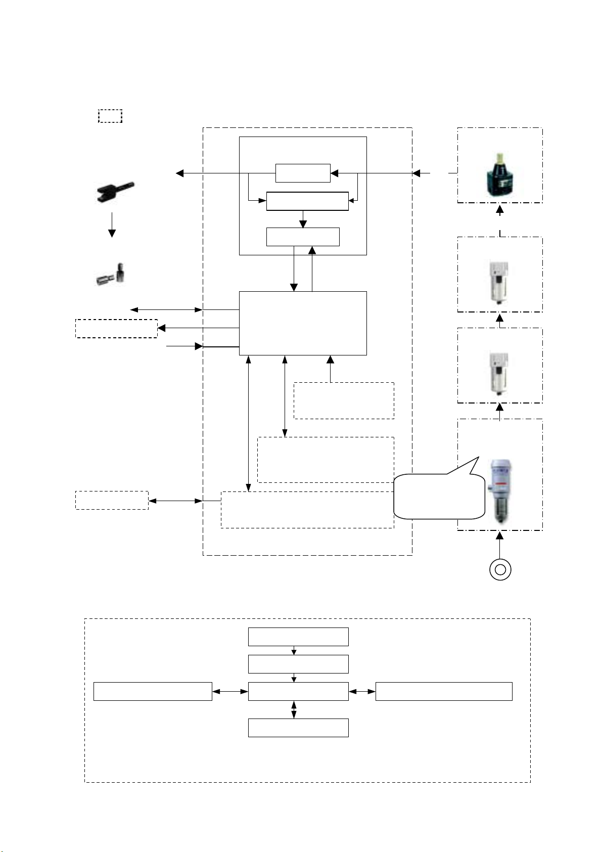
1.3 Block Diagram
•
d
t
p
(1) Structure
Arrow represents the direction of air and electric signal.
DIGITAL AIR MICROMETER USERS MANUAL (Second Edition)
is optional.
Measurement
element/tool
Work and master
RS232C
Digimatic output
External input button
A/E Converter
Air circuit
Pressure sensor
Amp circuit
Input Range switch
CPU
Memory for
operation software
Regulator
0.196±0.005MPa
0.3~0.7MPa
Mist separator
Filter
Parallel I/O
Memory for saving settings
values and master calibration
data (good for 10 types)
Optional
DC I/O base
In case industrial
ressure contains
moisture and oil
(2) Operation flow
Shown below is the software operations diagram starting from turning on power.
Power ON
Initialization mode
Reading of last setting values use
and master calibration data
• Confirmation of indicator ligh
(visual)
Master calibration mode
•
Master calibration
• Adjustment of detector
• Master calibration data clear
Measurement mode Program switching mode
Program switching
Setting mode
Measurement range selection
•
• Input of master value
• Input judgment limits
Can save up to 10 kinds of
settings values
Compressed air
purifier
Industrial pressure
5
Page 6
DIGITAL AIR MICROMETER USERS MANUAL (Second Edition)
•
d
y
t
–
d
•
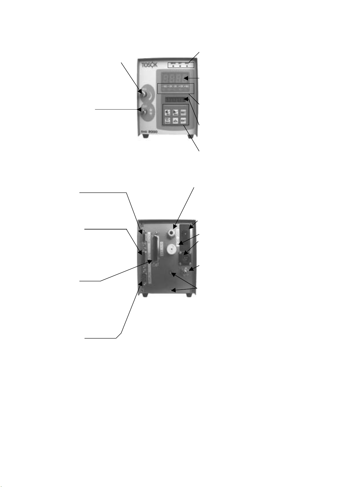
CHAPTER 2 NAME AND FUNCTION OF EACH PART
• Sensitivity (MAG) adjustment tuner
Adjusts the sensitivity of the air
circuit. No need for adjustments
except during measurement tool
replacement and master calibration
error.
• Zero adjustment tuner
Adjusts the zero position of the air
circuit. No need for adjustments
except during measurement tool
replacement and master calibration
error.
RS232C Connector
•
Connector for serial communications
used for connecting the PC to the
printer.
• Switch input connector
Connector for measurement comman
and master calibration input done b
external push button. Optional foo
switch and push button is available.
Cannot be used expect for foot switch
and push button.
• DC input connector
[Optional]
Connector for connecting to the lamp,
PLC, etc. There are 2 types
judgment output and BCD output.
Capable of measurement command an
master calibration input.
• Analog input connector
[Optional]
Please inquire to the maker on how to
use.
Mode lamp
Displays the current mode and master calibration
condition.
• Main display
4 digits 3 colors digital display. Displays the
measurement value and judgment result (rank no.).
• Judgment lamp
Displays the judgment results.
• English display
Displays simple bar, measurement value, settings
item name, settings value, etc.
• Panel switch
Used for mode switching, settings item selection,
settings value input, etc.
Air pressure input
Please supply pure air at 0.196±0.005MPa.
Optional precision regulator and filter is available.
• Power switch
• Silencer
• Power connector (Input)
Can be used at AC85~264V range but for the cable
included, please use within AC85~125V.
• Measurement nozzle port
Please connect measurement tool.
• Regulator bracket
Hole for fitting (M3)
6
Page 7
DIGITAL AIR MICROMETER USERS MANUAL (Second Edition)
•
•
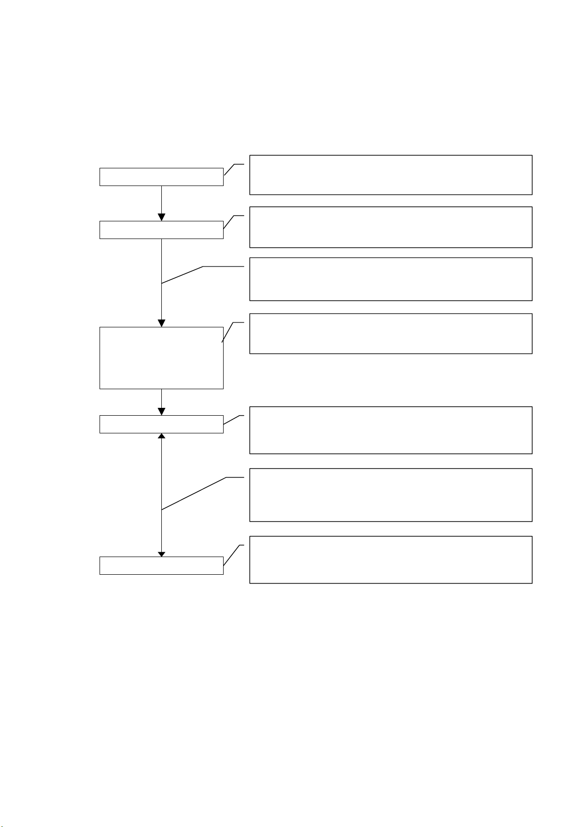
CHAPTER 3 PROCEDURE UP TO MEASUREMENT
Procedures up to the measurement corresponding to each condition are mentioned in this chapter.
3.1 For normal cases
Shown here is the procedure up to measurement for normal cases.
Turn ON compressed air
Supply of compressed air to the main body
Please refer to [Chapter 6, 6.2 Preparation] for details
Turn ON power
• Supply of power to the main body
Please refer to [Chapter 6, 6.3 Starting] for details
• Start at measurement mode
Please refer to [Chapter 6, 6.2 Preparation] for details
Switch to master calibration
mode (master calibration)
• Switch from measurement mode to master calibration mode
Please refer to [Chapter 4 Master Calibration] for details
Master calibration
• Record the master value to the main body
Please refer to [Chapter 4 Master Calibration] for details
Please perform master calibration regularly (every 2 hrs.).
Please refer to Chapter 4 Master calibration for details
After finishing master calibration, switch to measurement mode.
• Measurement is possible
Measurement
Please refer to [Chapter 5 Measurement] for details
7
Page 8
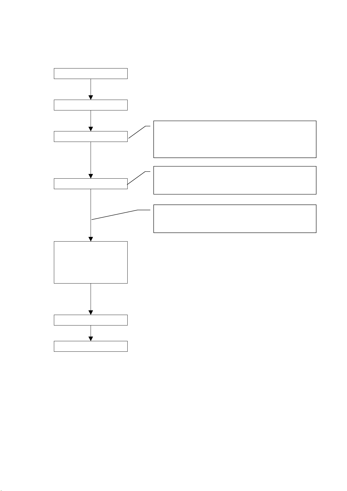
3.2 For work tolerance (judgment limits) change cases
t
Shown here is the procedure up to measurement wherein work tolerance is changed.
Turn on compressed air
Turn ON power
DIGITAL AIR MICROMETER USERS MANUAL (Second Edition)
Switch to settings mode
Change settings
Switch to master
calibration mode (master
calibration)
• Switch from measurement mode to settings mode
Because of work tolerance change, change the judgmen
limit values.
Settings value change can be done in setting mode.
Please refer to [Chapter 6, 6.4 Settings] for details.
• Switch to measurement mode after finishing settings change
Please refer to [Chapter 6, 6.4 Settings] for details.
• Change the judgment limit values at settings mode
Please refer to [Chapter 6, 6.4 Settings] for details.
Master calibration
Measurement
8
Page 9
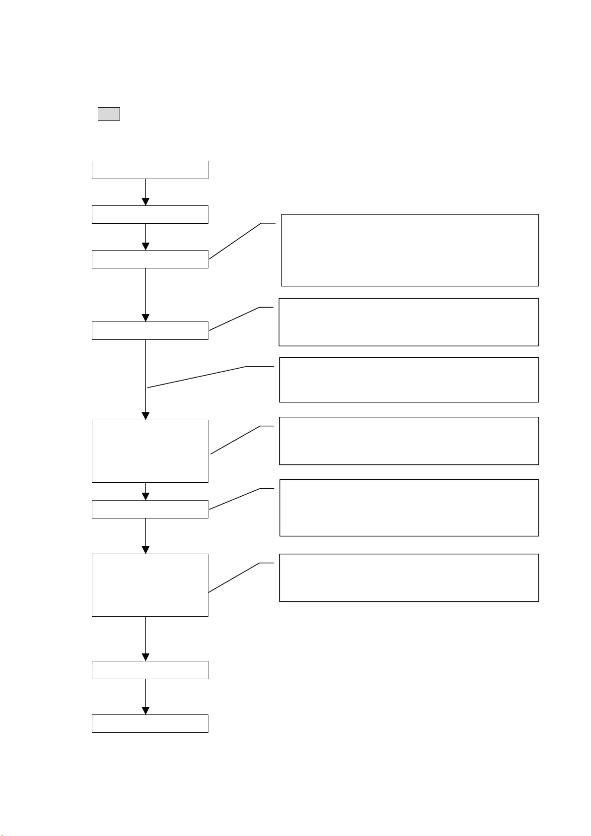
3.3 For first time measurement tool connection cases
t
r
r
r
Shown here is the procedure up to measurement wherein measurement tool is connected to the
main body for the first time.
Note: There are cases wherein detector adjustment is not needed depending on the measurement
tool.
DIGITAL AIR MICROMETER USERS MANUAL (Second Edition)
Turn ON compressed air
Turn ON power
Switch to settings mode
• Switch from measurement mode to settings mode
Because of work tolerance change, change the judgmen
limit values.
Settings value change can be done in setting mode.
Please refer [Chapter 6, 6.4 Settings] for details
Change the settings
• At settings mode, input the settings value for the
measurement tool that will be connected.
Please refer to [Chapter 6, 6.4 Settings] for details
• Switch to measurement mode after finishing settings
change
Please refer to [Chapter 6, 6.4 Settings] for details
Switch to master
calibration mode
(detector adjustment)
• Switch from measurement mode to detector adjustment
Please refer to [Chapter 6, 6.5 Detector Adjustment] fo
details
Detector adjustment
• Adjustment of detector through ZERO and sensitivity
tuner.
Please refer to [Chapter 6, 6.5 Detector Adjustment] fo
details
Switch to master
calibration mode (master
calibration)
Master calibration
Measurement
• Switches from detector adjustment to master calibration
Refer to [Chapter 6, 6.5 Detector Adjustment] fo
details.
9
Page 10
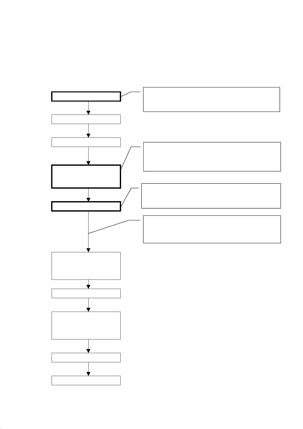
3.4 For several measurement tools connection cases
r
d
r
m
r
Shown here is the procedure up to measurement for cases wherein multiple measurement tools are
connected to 1 main body.
DIGITAL AIR MICROMETER USERS MANUAL (Second Edition)
Please refer to [Chapter 3, 3.3
For first time measurement tool connection cases] when inputting of
settings for measurement tools that will be connected are not finished.
Replace the measurement tool
Turn ON compressed air
Turn ON power
Switch to program switching
mode
Program switching
• Stopping of compressed air to the main body and replace
measurement tool.
Please refer to [Chapter 6, 6.2 Preparation] for details
• Switch from measurement mode to program switching
mode
Please refer to [Chapter 6, 6.6 Program Switching] fo
details
• At program switching mode, reads the settings value an
master data of the measurement tool connected.
Please refer to [Chapter 6, 6.6 Program Switching] fo
details
Switch to master calibration
mode (detector adjustment)
Adjustment of detector
Switch to master calibration
mode (master calibration)
Master calibration
• Switch to measurement mode after finishing progra
switching.
Please refer to [Chapter 6, 6.6 Program Switching] fo
details
Measurement
10
Page 11
DIGITAL AIR MICROMETER USERS MANUAL (Second Edition)
)
CHAPTER 4 MASTER CALIBRATION
This product is a comparison measurement device therefore master calibration (correction of
measurement value) by the use of a master is necessary.
Also, precise measurements can be made possible by regularly doing master calibrations.
There are 2 selections of master calibration method for this product:
• Master calibration (ZERO and sensitivity correction) by 2 masters (small range and big range).
• Master calibration (ZERO correction only) by 1 master (ZERO master).
At the [Cal Mode] of the settings item, 2 masters master calibration will be performed when [MIN
& MAX] is selected. 1 master calibration will be performed when [ZERO M.] is selected.
CAUTION
• Please perform again master calibration when ZERO and sensitivity tuning is operated after
master calibrations.
• Master calibration is NG when the mode lamp [MAS] lights up in red.
Please perform master calibration.
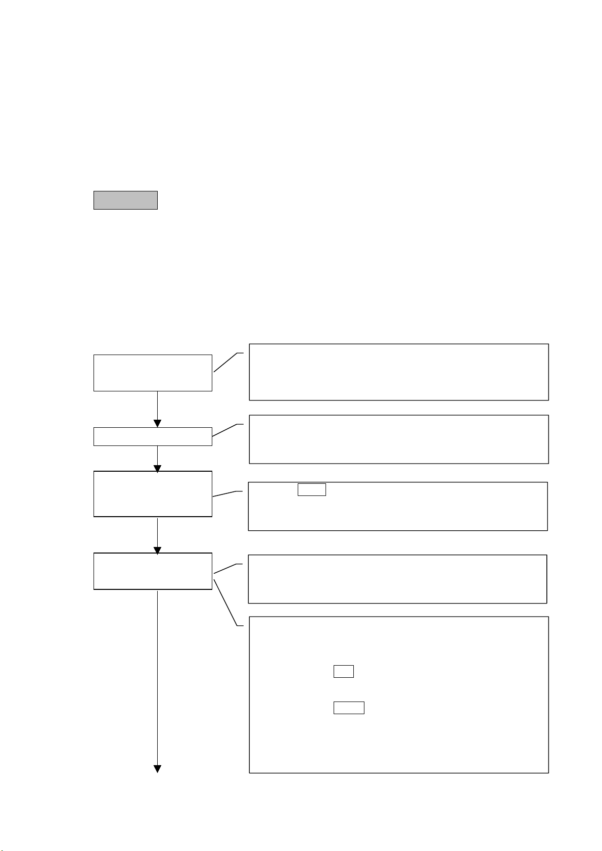
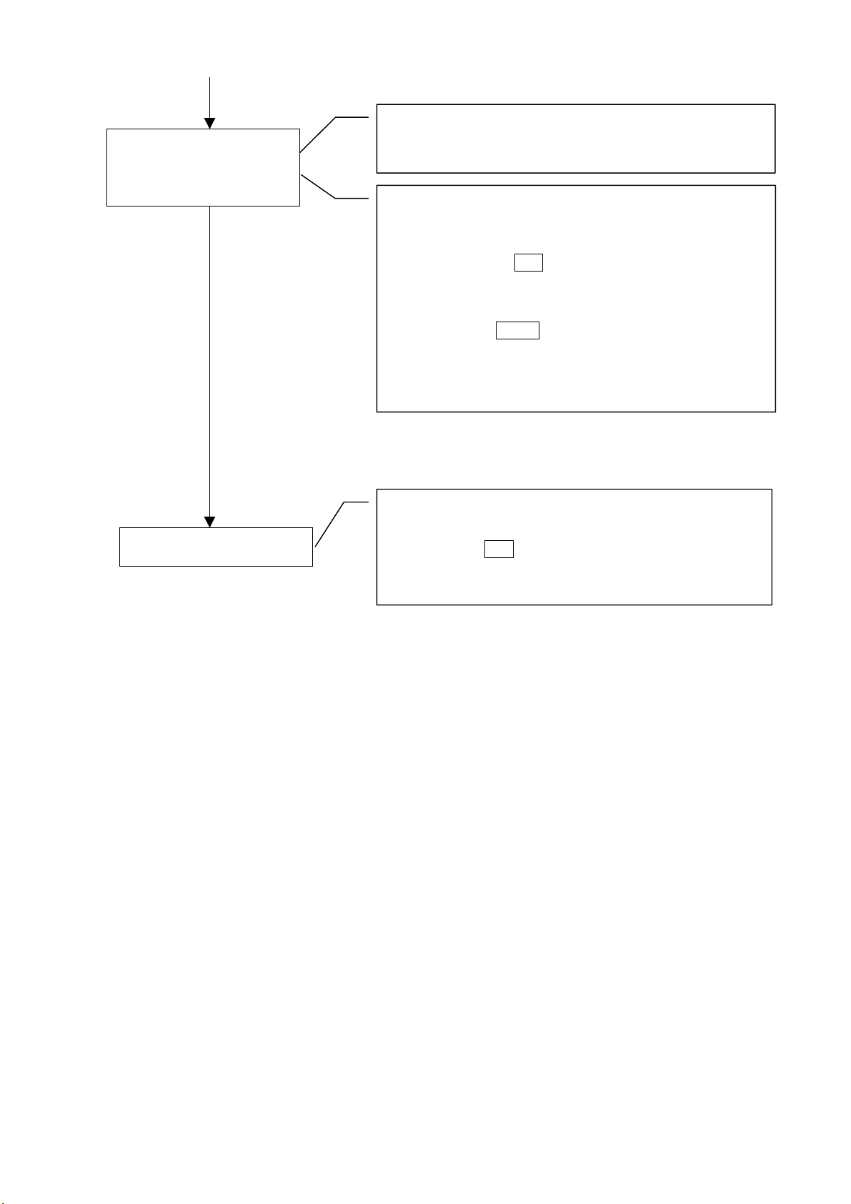
4.1 Master calibration by 2 masters
Shown here is the method for performing ZERO correction by small range master and sensitivity
correction by large range master.
Will be activated by selecting [MIN & MAX] at settings item [CalMode]
Confirmation of master
and measurement tool
① Please confirm that there are no foreign objects sticking on the
master or measurement tool. In case there are foreign objects,
this will have bad effect on the master calibration and
measurement cannot be performed correctly.
Measurement mode
Switch to master
calibration mode (master
calibration)
Small range master
calibration (ZERO
correction
Please confirm that it is in measurement mode (mode lamp
[MEAS] will light up).
Please refer to [Chapter 5 Measurement] for details
Press /
Will switche from measurement mode to master calibration mode
(master calibration)
After “MIN M.” in the English numbers display has been
displayed for 2 seconds, raw data will be displayed.
Mode lamp [MAS] with orange color with light up.
Please set the small range master to the measurement tool.
Raw data (without correction) is displayed in the main display.
Raw data display colors are:
• When color is green, ZERO master calibration is possible.
Please press ENT. ZERO correction will be performed.
• When color is red, ZERO master calibration is not possible.
Detector adjustment will be performed.
Please press /
“ADJ.” will be shown in the English figures display and will
switch to detector adjustment.
Please refer to [Chapter 6, 6.5 Detector Adjustment] for details.
continuously for 2 seconds.
MAS
.
MAS
11
Page 12
DIGITAL AIR MICROMETER USERS MANUAL (Second Edition)
r
r
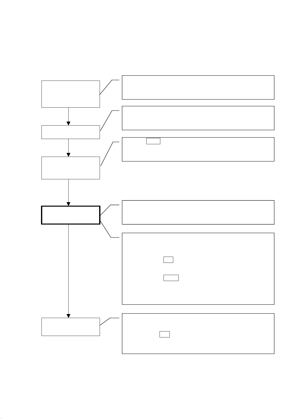
Large range master calibration
(Sensitivity correction)
Master calibration completion
⑥ After “MAX M.” shown in the English display for
2 seconds, data after ZERO correction will be shown.
Please set the large range master to the measurement tool.
ZERO correction data will be shown in the main display.
ZERO correction data display colors are:
• Green - sensitivity master calibration is possible.
Please press ENT. Sensitivity correction will be
performed.
• Red - sensitivity master calibration is not possible.
Detector adjustment will be performed.
Please press /
“ADJ.” will be shown in the English display and will
switch to detector adjustment.
Please refer to [Chapter 6, 6.5 Detector Adjustment] fo
details.
“MAS OK” will be shown in the English display and will
switch to measurement mode.
Master calibration has error if anything else is displayed.
Please press ENT and repeat from .
About the master calibration error, please refer to [3.4 Maste
calibration Error].
MAS
.
12
Page 13
DIGITAL AIR MICROMETER USERS MANUAL (Second Edition)
r
t
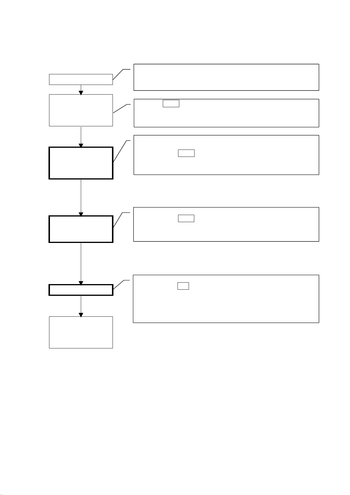
4.2 Master calibration by 1 master
Shown here is the method on how to perform ZERO correction by ZERO master.
Valid for cases when [ZERO M.] in the [CAL MODE] settings item is selected.
Sensitivity correction data will use the master calibration results of the 2 masters performed previously.
If 2 masters adjustment has not been performed, please perform first [Chapter 6, 6.5 Detector
Adjustment].
Confirmation of master
and measurement tool
Please confirm that there are no foreign objects sticking on the
master or measurement tool. In case there are foreign objects, this
will have bad effect on the master calibration and measuremen
cannot be performed correctly.
Measurement mode
Please confirm that it is in measurement mode (mode lamp [MEAS]
will light up).
Please refer to [Chapter 5 Measurement] for details
Switch to master
calibration mode (master
calibration)
Press /
Will switch from measurement mode to master calibration mode
(master calibration)
continuously for 2 seconds.
MAS
ZERO master calibration
(ZERO correction)
After “MIN M.” in the English display has been displayed for 2
seconds, raw data will be displayed.
Mode lamp [MAS] with orange color with light up.
Please set the ZERO master to the measurement tool.
Raw data (without correction) is displayed in the main display.
Raw data display colors are:
• When color is green, ZERO master calibration is possible.
Please press ENT. ZERO correction will be performed.
• When color is red, ZERO master calibration is not possible.
Detector adjustment will be performed.
Please press /
“ADJ.” will be shown in the English figures display and will
switch to detector adjustment.
Please refer to [Chapter 6, 6.5 Detector Adjustment] for details.
MAS
.
Master calibration
completion
“MAS OK” will be shown in the English display and will switch to
measurement mode.
Master calibration has error if anything else is displayed.
Please press ENT and repeat from .
About the master calibration error, please refer to [3.4 Maste
Calibration Error].
13
Page 14
DIGITAL AIR MICROMETER USERS MANUAL (Second Edition)
r
r
4.3 Clearing of master data
Shown here is the clearing method of ZERO correction and sensitivity correction data
Ordinarily not used. Please use for wear check of measurement tool.
Measurement mode
Please confirm that it is in measurement mode (mode lamp [MEAS]
will light up).
Please refer to Chapter 5 Measurement for details
Switch to master
calibration mode
(master calibration)
Press /
Will switch from measurement mode to master calibration mode
(master calibration)
continuously for 2 seconds.
MAS
Switch to master
calibration mode
(detector adjustment)
Switch to master
calibration mode
(Clears master data)
Clear master data
Switch to master
calibration mode
(master calibration)
After “MIN M.” or “ZERO M.” has been shown in the English
display, mode lamp [MAS] with orange color with light up.
Please press /
Switches from master calibration mode (master calibration) to maste
calibration mode (detector adjustment)
“ADJ.” will be shown in the English display.
Please press /
Switches from master calibration mode (detector adjustment) to maste
calibration mode (master data clear)
“MST CLS.” will be shown in the English display.
Please press ENT.
Master data will be cleared.
After “M. CLS OK” has been shown in the English display, mode
lamp [MAS] with orange and red colors with light up alternately.
Returns to condition .
MAS
MAS
.
.
4.4 Master calibration error
In case of master calibration error, the following error details will be shown in the English display:
“ERR ZERO” ZERO correction is out of range
“ERR MAG” Sensitivity correction is out of range
“ERR REV” Data during ZERO correction is smaller than data during sensitivity
correction
In case the above errors are displayed, it is necessary to adjust through the ZERO/sensitivity
adjustment tuner.
Please refer to [Chapter 6, 6.5 Detector Adjustment] for details.
14
Page 15
DIGITAL AIR MICROMETER USERS MANUAL (Second Edition)
CHAPTER 5 MEASUREMENT
Measurement is possible when [MEAS] mode lamp is lit and LED of [MAS] is unlit.
If [MAS] LED is blinking, this means that master calibration has not been performed so please
perform first [Chapter 4 Master Calibration].
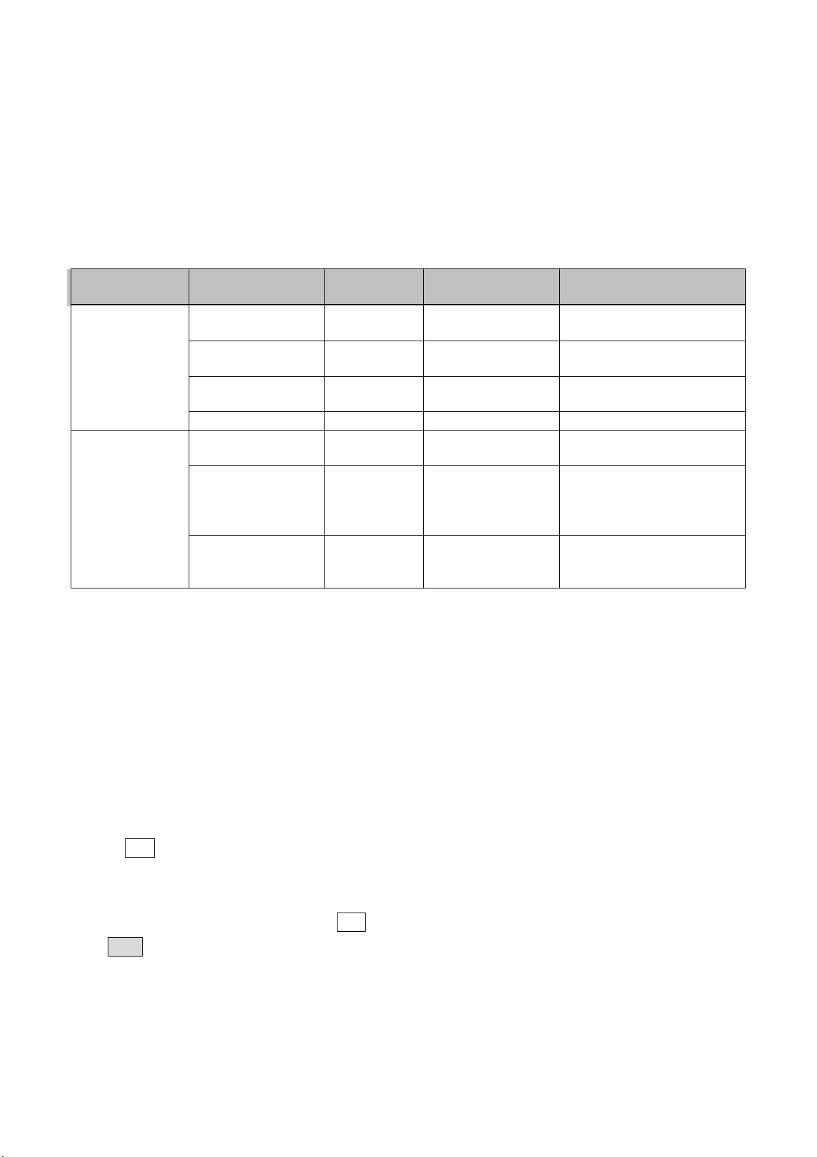
5.1 Measurement value display
Display contents for the main display and English display can be changed by setting it.
Display device Display contents Settings item
Settings Remarks
name
Main display
Measurement value
[µm]
Measurement value
[mm]
MainDisp
MEASURED µm
Displays the measurement
value in µm
Ditto MEASURED mm Displays the measurement
value in mm
Judgment result Ditto JUDGMENT -OK=1, OK=2, +OK=3,
-NG & +NG=no display
Not used Ditto NO USE
English display
Measurement value
[mm]
CharDisp MEASURED Displays the measurement
value in mm
Judgment result Ditto JUDGMENT The left 3 digits is the
program number.
The right 4 digits is the
judgment result
Plain bar Ditto BAR Position display of
measurement value within
the measurement range
Please select in settings item [RESOLUTION] for the resolution function in the measurement values display.
5.2 Display color of main display
Display color of the main display changes depending on the judgment result.
If judgment result is:
OK, the color will be GREEN.
-OK and +OK, color will be ORANGE,
-NG and +NG, color will be RED.
5.3 Measurement value hold
If ENT command is inputted during measurement, measured value will be on hold (saved) and if
external I/F is being used, measurement value and judgment results will be outputted.
Also, display color will change from light to dark.
To cancel measurement value saving, RST or input RESET.
Note: Cannot hold (save) when master calibration in NG.
15
Page 16
DIGITAL AIR MICROMETER USERS MANUAL (Second Edition)
h
n
CHAPTER 6 DETAILS OF EACH PROCEDURE
6.1 Installation
Please place the main body and measurement tool on a location that can withstand heavy weight and
that is stable.
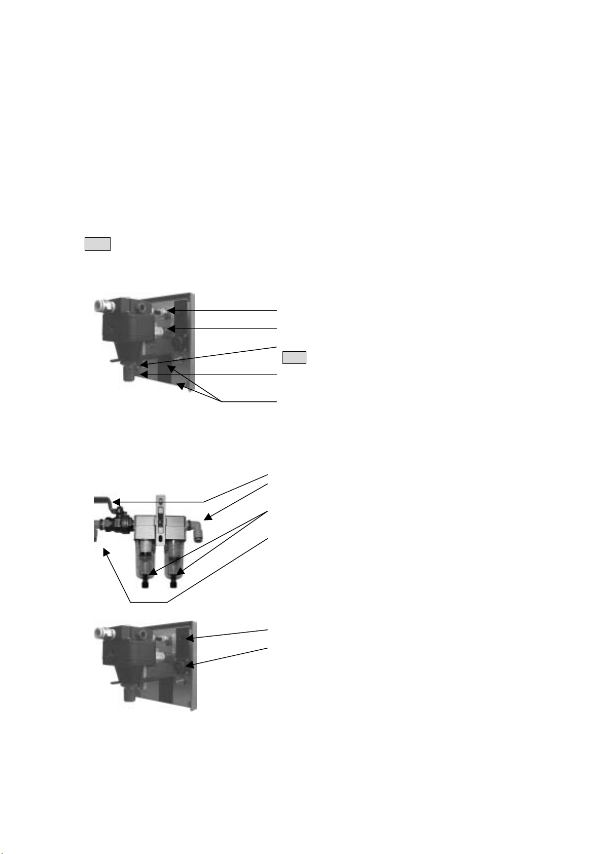
6.2 Preparation
(1) Air piping
Pipe layout for the air to be used in measurement.
Please supply pure air with dirt, moisture, and oil removed.
Please prepare air environment friendly high performance filter.
Note: Please make sure to connect in such a way that air does not leak when connecting the hose to the
joint.
a) Connection of main body and regulator (optional)
Rear view of main body
b) Connection of filter (optional)
① Please connect hose (outer diameter 6, inner diameter 4, lengt
50) to the regulator joint (OUT).
② Please connect the silencer.
③ Please fit the regulator bracket to the regulator.
Note: Please do not touch the regulator pressure adjustment part
since regulator pressure has already been adjusted to
0.196±0.005Mpa.
④ Please fix the regulator bracket to the regulator bracket hole
(M3).
① Please turn the COCK off.
② Please connect the hose (outer diameter 8, inner diameter 6) i
between the filter and regulator.
③ Please fix the screw for draining so that it faces downwards.
Turn counterclockwise and please drain 1 or more times per day.
④ Please supply compressed air (0.3 ~ 0.7Mpa)
(2) Connection of power cable
① Please set the power switch to OFF ( will come out).
② Please connect the power cable to the power connector (input).
For the power cable included, please use within AC85 ~ 125V.
16
Page 17
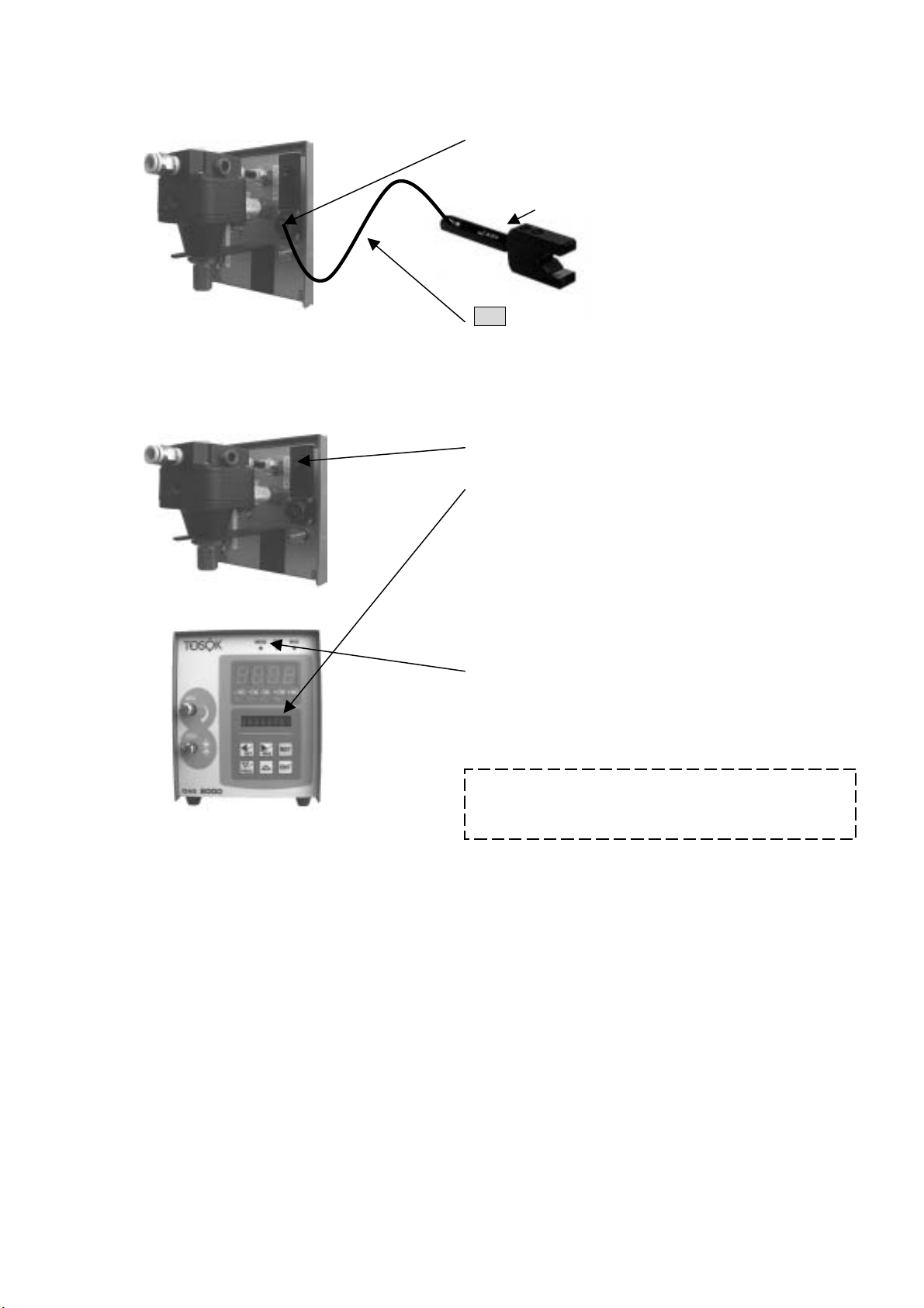
(3) Connection of measurement tool
r
DIGITAL AIR MICROMETER USERS MANUAL (Second Edition)
6.3 Starting
① Please connect the measurement element o
measurement tool to the measurement nozzle
port.
Measurement element
(PO type, POT type)
Note: If hose length is long, this will have effect on the
responsiveness.
① Please switch On the power switch (press ).
② The following are shown in the English display:
• Software version
• Option information
③ Last used values of the following will be read:
• Settings value
• Master calibration data
④ Confirms (visual) the lighting of the display device.
⑤ Starts in the measurement mode (mode lamp
[MEAS] lights up).
Point
Measurement mode will start right after turning on power.
(mode lamp [MEAS] lights up)
17
Page 18
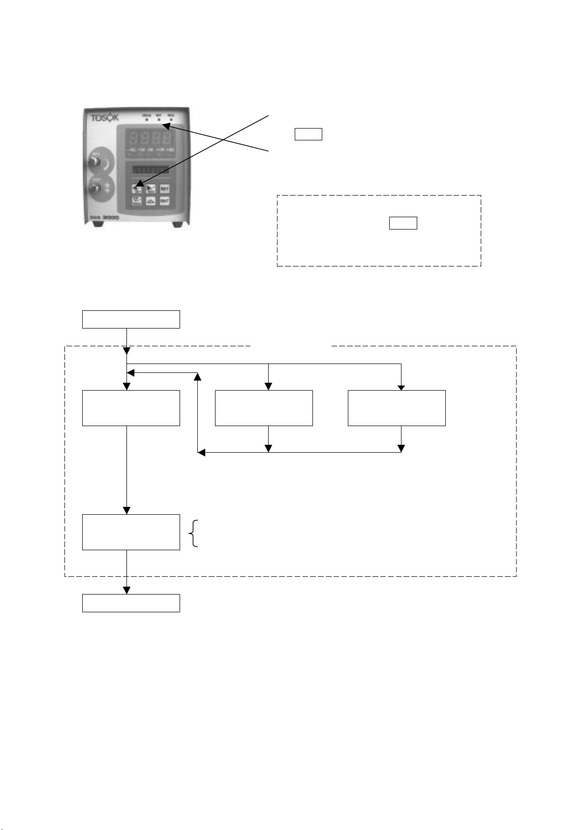
6.4 Settings
r
(1) How to switch to settings mode
DIGITAL AIR MICROMETER USERS MANUAL (Second Edition)
(2) Structure of settings mode
Measurement mode
Standard settings
(Normal)
① At settings mode (mode lamp [MEAS] is lit), please press
② Switches to settings mode (mode lamp [SET] lights up in
Point
At measurement mode, if /
2 seconds, mode will switch to settings mode
(mode lamp [SET] will light up in orange color)
Settings mode
Detailed settings
(Detail)
/
continuously for 2 seconds.
SET
orange color).
System settings
SET
(System)
is pressed fo
End of settings mode
(END)
Measurement mode
• Cancel settings values (CANCEL)
• Refresh settings values (WRITE)
18
Page 19

DIGITAL AIR MICROMETER USERS MANUAL (Second Edition)
(3) Settings details
This explains the settings item name and settings details at the settings mode.
Settings mode is mainly divided into the following 3:
• Normal [Standard settings] --- master values, judgment limit values can be set
• Detail [Detailed settings] --- measurement range, display analysis function, polarity ditto
• System [System settings] --- display data, moving average ditto
① Settings item names and settings details at Normal [Standard settings]
Settings concerning master values
• [MIN M.] --- Please input the small range master values used in master calibration (2 masters).
• [MAX M.] --- Please input the large range master values used in master calibration (2 masters).
• [ZERO M.] --- Please input the ZERO master values used in master calibration (1 master).
Settings concerning judgment limit values
• [-NG/-OK] --- Please input the limit values of –NG and -OK
• [-OK/ OK] --- Please input the limit values of –OK and OK
• [ OK/+OK] --- Please input the limit values of OK and +OK
• [+OK/+NG] --- Please input the limit values of +OK and +NG
In case judgment of –OK is not needed, please set the same settings values to [-NG/-OK] and
[-OK/OK] and in case judgment of +OK is not needed, please set the same settings values to
[OK/+OK] and [+OK/+NG].
Settings concerning master
• [CORRECT] --- Machine difference correction values can be set
Adds and displays the above data to the master correction data.
② Settings item name and settings details at Detail [Detailed settings]
• [RANGE] --- Measurement range can be selected
10µm is optional.
• [RESOLUTION] --- display analysis function ditto
Settings concerning detector
• [POL] --- Polarity
Please select + for inner diameter measurement and – for outer dimension measurement
• [GAIN] --- Sensitivity rough adjustment values can be set
Normally, settings values is fixed depending on the selected measurement range.
Please input:
24 if measurement range 100µm is selected
33 if measurement range 50µm is selected
68 if measurement range 20µm is selected
(204 if measurement range 10µm is selected)
In case measurement range is changed, the above values will be set.
• [CONSTANT] --- Sensitivity fine adjustment constant can be set
Normally, please input 1.000.
Settings concerning master
• [CalMode] --- Master calibration method can be selected
Please select:
[MIN & MAX] for master calibration by small range or large range master.
[ZERO M.] for master calibration by ZERO master.
③ Settings item name and settings details at System [System settings]
• [MEAS SW] --- External button input movement can be selected
• [SMOOTH] --- Moving average ditto
Settings concerning display
Data shown in:
• [MainDisp] --- Main display can be selected
• [CharDisp] --- English display ditto
19
Page 20
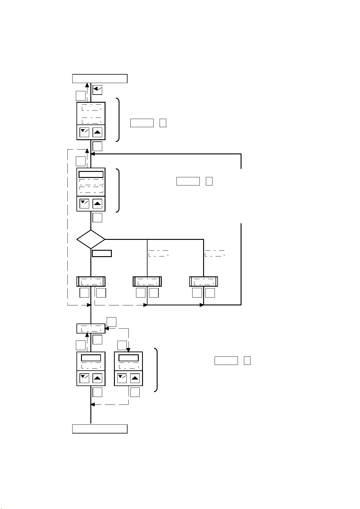
(4) Operation flow at settings mode
r
N
Shown here is about the settings mode operation.
① Whole, general, entire
[Measurement mode]
for 2 seconds
SETSET
RST
DIGITAL AIR MICROMETER USERS MANUAL (Second Edition)
PROG[10]
~
PROG[ 1]
PROG
RST
Normal▼
Detail▼▲
System ▲
PROG
Normal
ENT
ENT
Normal
is selected
●Selection of program number to perform settings
Please select the program number that you want to perform with the
▽ /
PROG
△.
Start the measurement with the selected program number afte
finishing settings change
●Selection of settings mode
Please select with ▽ /
PROG
△.
Settings change of the following are possible
ormal [Standard settings] --- master values, judgment limit values
Detail [Detailed settings] --- measurement range, display analysis function
System [System settings] --- display data, moving averages frequency
Detail
is selected
Detail System
System
is selected
RST
ENT
RST
END
ENT
RST
WRITE
CANCEL
PROG
ENT
RST
PROG
[Measurement mode]
CANCEL
WRITE
ENT
RST
ENT
RST
ENT
●Saving of settings values
Please select with ▽ /
PROG
△.
Please select WRITE to save the settings values.
Settings values will be changed.
Please select CANCEL to cancel the settings values.
Returns to the previous settings values.
20
Page 21
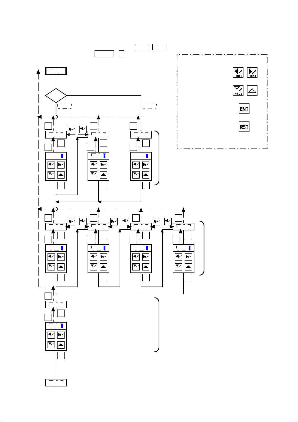
② Normal [Standard settings]
Please select the input digit with the
input values using ▽ /
PROG
Normal
△.
/
SET /MAS
DIGITAL AIR MICROMETER USERS MANUAL (Second Edition)
to change the settings values and change the
●Setting values inputting method.
・Selection of input digit
CalMode
MIN&MAX
is selected is selected
RST
MIN M.
MASMAS
ENT
012.3450
SETSET
MASMAS
PROG
-NG/-OK
RST
ENT
MASMAS
ENT
※1 ※2 ※3
012.3450
SETSET
MASMAS
RST
SETSET
MAX M.
ENT
RST
012.3750
SETSET
MASMAS
PROG
ENT
SETSET
-OK/ OK OK/+OK +OK/+NG
RST
MASMAS
ENT ENT ENT
012.3550
SETSET
MASMAS
RST
RSTRST
SETSET
RST
ZERO M.
012.3450
SETSET
PROG
012.3650
SETSET
ZERO M.
ENT
MASMAS
ENT
MASMAS
・Input values change
・Confirmation of input value
・Input cancel
(Reads the previous settings values)
●Master values settings
※1:Small range master values.
※2:Large range master values.
※3:ZERO master values.
RSTRSTRSTRST
SETSET
MASMAS
RST
012.3750
SETSET
MASMAS
●Judement limit values settings
※4:-NG/-OK
※5:-OK/ OK
※6: OK/+OK
PROG
※4 ※5 ※6 ※7
ENT
RST
PROG
ENT
PROG
ENT
CORRECT
●Master settings
ENT
RST
※8:Machine difference correction values.
+0.0000
SETSET
MASMAS
PROG
※8
ENT
END
21
PROG
※7:+OK/+NG
ENT
Page 22
DIGITAL AIR MICROMETER USERS MANUAL (Second Edition)
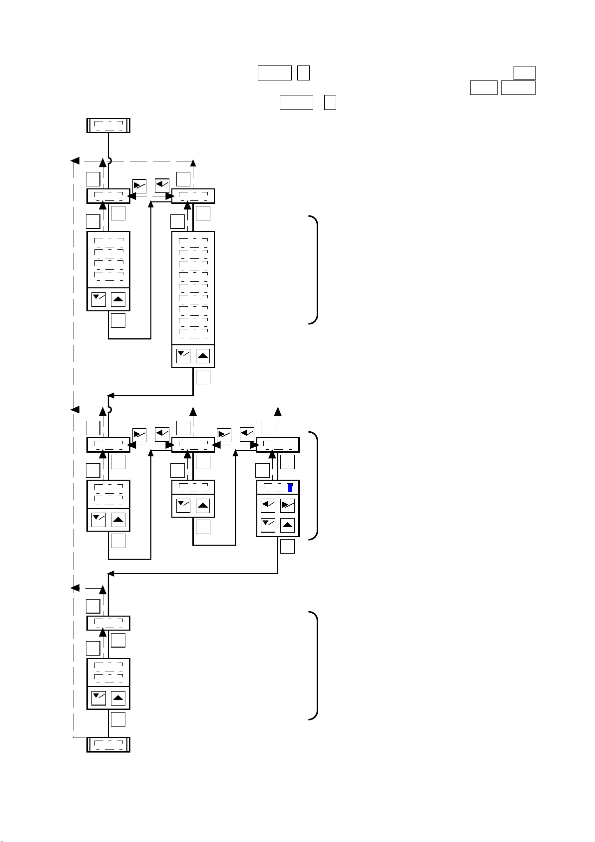
③ Detail [Detailed settings]
Please change the settings with ▽/
△. Confirm the settings value by pressing ENT.
PROG
Sensitivity fine adjustment constant (✻ 5) is selected by inputting the digit with 3/
and please change the input value with ▽/
Detail
PROG
△.
SET
4/
MAS
,
RST
RANGE
ENT
RST
100μm
50μm
20μm
10μm
PROG
※1
ENT
ENT
RST
+
-
PROG
ENT
※3 ※4
MASMAS
MASMAS
SETSET
※2
SETSET
RST
RESOLUTI
RST
5μm
2μm
1μm
0.5 μm
0.2 μm
0.1 μm
0.05μm
0.02μm
0.01μm
PROG
RST
PROG
ENT
ENT
ENT
ENT
※1:Measurement range
※2:Display resolution
RSTRSTRST
SETSET
MASMAS
24
RST
CONSTANTPOL GAIN
SETSET
PROG
ENT
1.000
ENT
MASMAS
●Detector settings
※3:Polarity selection.
※4:Sensitivity rough adjustment values.
※5:Sensitivity fine adjustments contants.
※5
RST
RST
PROG
※6
CalMode
MIN&MAX
ZERO M
Normal
ENT
ENT
●Master setting
※6:Selection of master calibration method.
22
Page 23
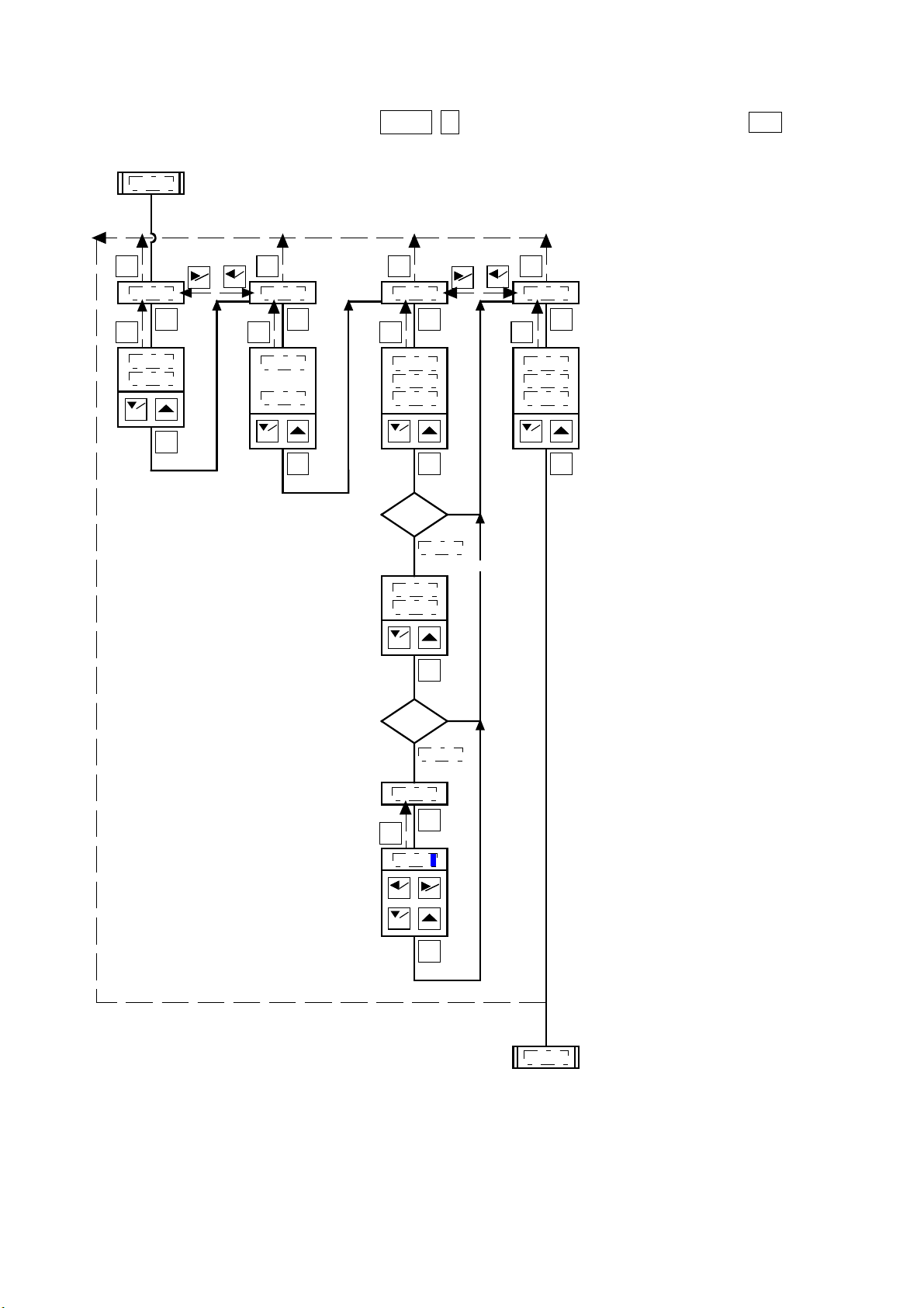
④ System [System settings]
DIGITAL AIR MICROMETER USERS MANUAL (Second Edition)
Please change the settings with ▽/
System
SETSET
MEAS SW SMOOTH
RST
NOT HOLD
PROG
※1
MASMAS
ENT
HOLD
ENT
RSTRST
RST
PROG
※2
ENT
30TIMES
~
ONCE
ENT
RST
※3
※4
△. Confirm the settings value by pressing ENT.
PROG
RSTRST
SETSET
ENT
ENT
MASMAS
CharDisp
ENT
RST
MEASURED
JUDGMENT
BAR
PROG
ENT
MainDisp
MEASURED
JUDGMENT
NO USE
PROG
※5
MEASURED
is selected
μm
mm
PROG
ENT
※1:External button movement.
※2:Moving average frequency.
●Display settings
Selection of display data at measurement mode
※3:Data shown in main display.
※4:Unit.
DIMENSIO
RST
SETSET
PROG
※5:Data shown in English display.
μm
is selected
ENT
1.0000
MASMAS
ENT
Normal
23
Page 24
t
d
6.5 Detector Adjustment
Please perform detector adjustment when measurement tool is replaced.
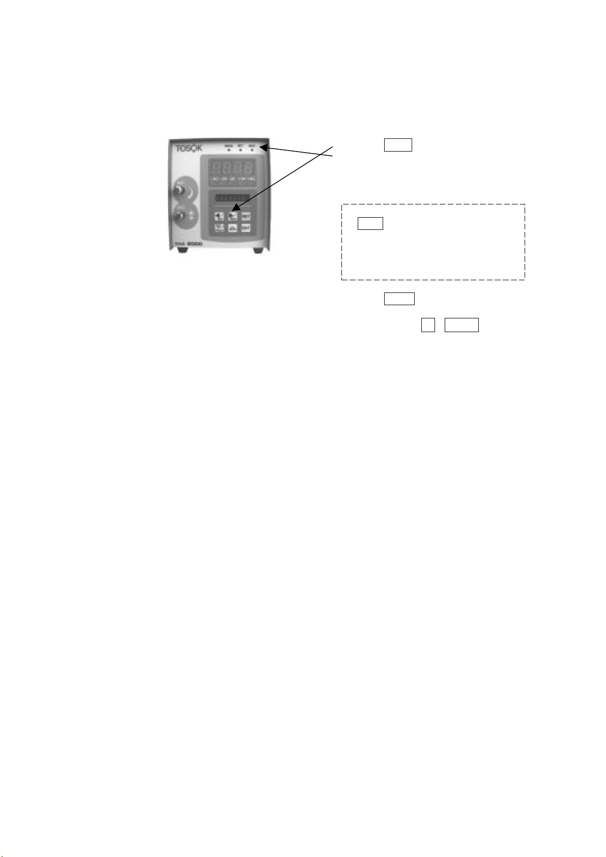
(1) How to switch to master calibration method
DIGITAL AIR MICROMETER USERS MANUAL (Second Edition)
(2) Detector adjustment
① Press /
② Switches to master calibration mode
(mode lamp [MAS] lights up in orange
color)
Point
If /
SET
for 2 seconds, mode will switch to
settings mode.
(mode lamp [MAS] will light up in
orange color)
③ Press /
④ Adjustment of detector
⑤ By pressing △ ▽ /
values of sensitivity rough adjustmen
[GAIN] can be changed.
Ordinarily, there is no need to change.
continuously for 2 seconds.
MAS
at measurement mode is presse
once.
MAS
, settings
PROG
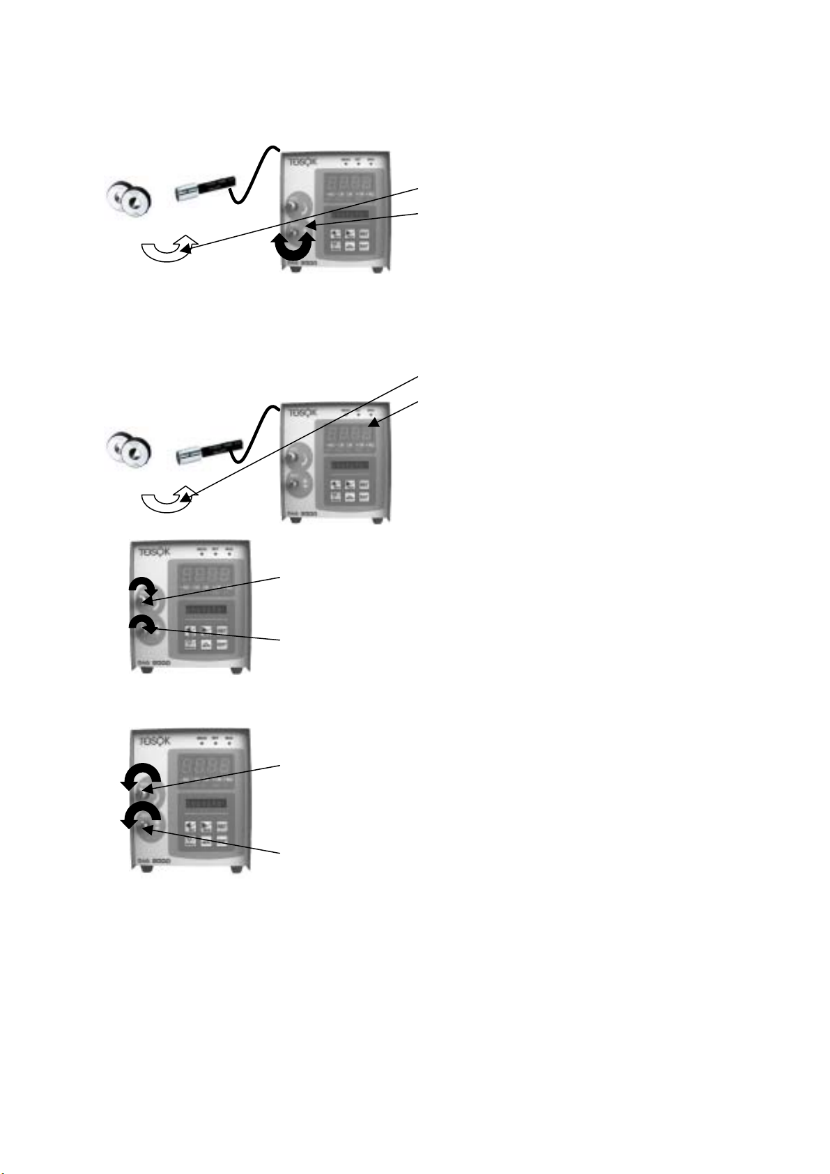
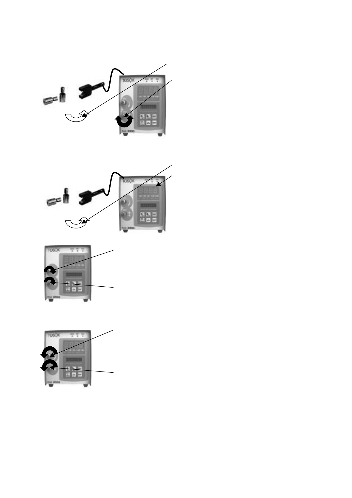
Adjustment method for inner diameter measurement and outer diameter measurement is different.
For inner diameter measurement, small range master is adjusted through ZERO position and large
range is through sensitivity adjustment. Please refer to 1).
For outer diameter measurement, large range master is adjusted through ZERO position and small
range is through sensitivity adjustment. Please refer to 2).
24
Page 25
t
h
t
r
r
1) For inner diameter measurement
DIGITAL AIR MICROMETER USERS MANUAL (Second Edition)
MASTER
Small range (left)
Large range (right)
MASTER
Small range (left)
Large range (right)
Measurement tool
Measurement tool
(1) Set the small range master to the measuremen
tool
(2) Turn the ZERO adjustment tuner and adjust the
readings on the main display so that the value is
close to the master value.
(3) Set the large range master to the measurement
tool
(4) In the main display, if value:
• Is near the large range master, calibration is
finished. Please perform (7).
• Is not attained, sensitivity is insufficient.
Please perform (5).
• Exceeds, there is over sensitivity. Please
perform (6).
(5) In case of insufficient sensitivity
a) Turn the sensitivity adjustment tuner clockwise wit
the large range master set to the measurement tool.
Please add from the large range master value 5 times
the minus amount from the large range master value.
b) Turn the ZERO adjustment tuner clockwise and adjus
to the large range master value.
c) Please repeat starting from (1)
(6) In case of over sensitivity
a) Turn the sensitivity adjustment tune
counterclockwise with the large range master set to
the measurement tool.
Please subtract from the large range master value 5
times the plus amount from the large range maste
value.
b) Turn the ZERO adjustment tuner counterclockwise
and adjust to the large range master value.
c) Please repeat starting from (1)
(7) End of adjustment
Aside from these there is no need for adjustments using the tuner (excluding special cases).
Please proceed to (3).
25
Page 26
2) For outer diameter measurement
t
h
r
d
r
MASTER
Small range (left)
Large range (right)
Measurement tool
MASTER
Small range (left)
Large range (right)
Measurement tool
DIGITAL AIR MICROMETER USERS MANUAL (Second Edition)
(1) Set the large range master to the measurement
tool
(2) Turn the ZERO adjustment stop and adjust the
readings on the main display so that it becomes
near the value of the large range master.
(3) Set the small range master to the measuremen
tool
(4) In the main display, if shown is:
• Near the small range master calibration is
finished. Please do (7).
• Exceeding, sensitivity is insufficient.
Please do (5).
• Did not reach, there is over sensitivity.
Please do (6).
(5) In case of insufficient sensitivity
a) Turn the sensitivity adjustment tuner clockwise wit
the small range master set to the measurement tool.
Please subtract from the small range master value 5
times the plus amount from the small range maste
value.
b) Turn the ZERO adjustment stop clockwise an
adjust to the small range master value.
c) Please repeat starting from (1)
(6) In case of over sensitivity
a) Turn the sensitivity adjustment tune
counterclockwise with the small range master set to
the measurement tool.
Please add from the small range master value 5
times the minus amount from the small range
master value.
b) Turn the ZERO adjustment tuner counterclockwise
and adjust to the small range master value.
c) Please repeat starting from (1)
⑦ End of adjustment
Aside from these there is no need for adjustments through tuner (excluding special cases).
Please proceed to (3)
26
Page 27
DIGITAL AIR MICROMETER USERS MANUAL (Second Edition)
m
t
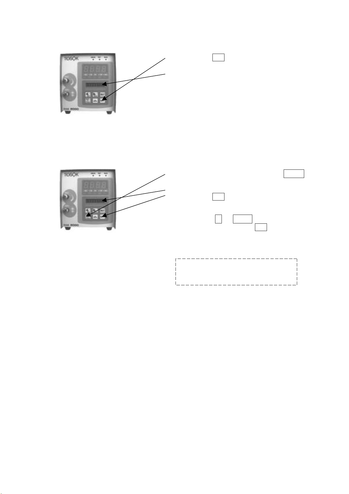
(3) Switching to master calibration mode (master calibration)
6.6 Program Switching
① Please press ENT.
② In the English display,
“MIN M.” or “ZERO M.” will be displayed.
“MIN M.” is for master calibration with 2
masters.
“ZERO M.” is for master calibration with 1
master.
Raw data (without correction) is shown in the
main display.
① At measurement mode, please press ▽ /
continuously for 2 seconds.
② “PROG” will appear in the English display.
③ Please press ENT.
The current program number being used will be
shown.
④ Please press △ or ▽/
number (0~9), and then press ENT.
⑤ Program switching mode ends and switches to
measurement mode.
, select the progra
PROG
PROG
Point
When the machine is powered on, it will star
with the last selected program number.
27
Page 28
DIGITAL AIR MICROMETER USERS MANUAL (Second Edition)
CHAPTER 7 EXTERNAL I/O FUNCTION
7.1 Serial (RS232C) communications function
(1) Outline
This product uses serial communications and is capable of outputting the measurement value and
judgement to the printer or PC.
(2) Preparation
The RS232C back side of the main body is the connection port to printer and PC.
Please connect to the main body the optional communications cable D-sub9P (OSS).
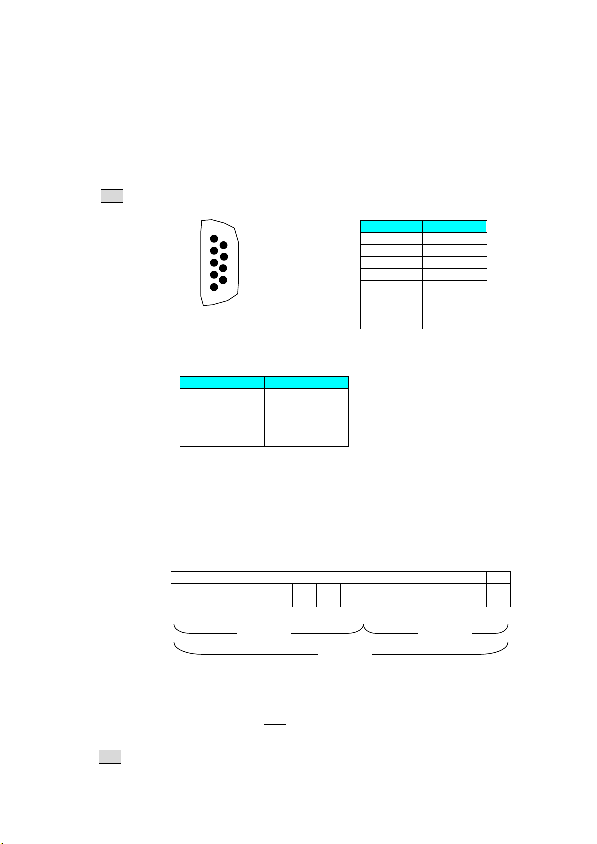
(3) RS232C Connector
Note: Please set the cable length within 15m.
1
2
3
4
5
6
7
8
9
Pin No. Signal name
1
2 RxD
3 TxD
4
5 GND
6
7 RTS
8 CTS
(4) Serial port settings
Settings name Settings details
Bow rate
Bit/letter
Stop bit
Start bit
Parity bit
9600
8
1
1
none
(5) Measurement results output
Outputs the measurement value and judgment result.
① Simple command
Please transmit “D” only. Returns the output data of ② (below).
② Simple output data
Returns the data shown below:
Letter:
ASCII code:
Example:
20 20 31 2E 32 33 34 35 20 20 4F 4B 0D 0A
SP SP 1 . 2 3 4 5 SP SP O K CR LF
✻ SP represents SPACE.
Measurement value SP Judgment CR LF
8 letters 3 letters
14 letters
Judgment is outputted as “-NG”, “-OK”, “OK”, “+OK”, “+NG”
(6) Data transmission method from the main body
At measurement mode, please press ENT or the measurement button (refer to 7.2 External button
input for details).
Transmits in [(5) Simple Output Data] format.
Note: Data cannot be transmitted when master calibration is NG.
28
Page 29
7.2 External button input
(1) Outline
This device allows the connection of the non-electrical contact of the external button or foot switch
to the [SW, ETC] at the back of the main body.
Measurements, RESET, large range master calibrations, and small range master calibrations can be
performed.
(2) Preparation
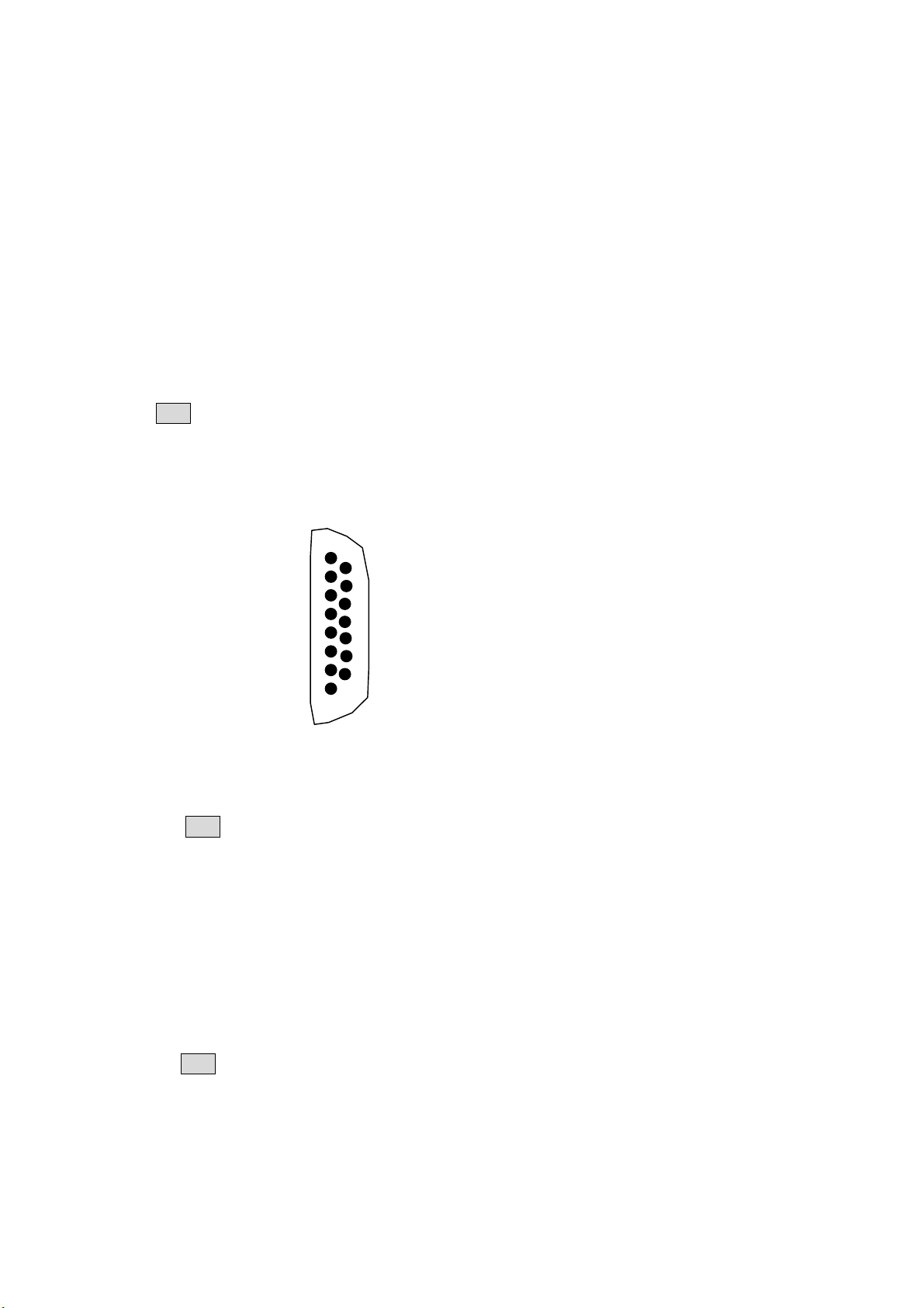
[SW. ETC] at the back of this device is the connection port to the external button.
D-sub 15P (OSS) can be connected.
(3) Switch input connector
External button and also non electric contacting foot switch can be connected.
Input can be activated by short circuiting to the ground pin (6).
Please use D-sub 15P (OSS).
Note: Please set the cable length within 2m.
Cannot use other than push button or foot switch.
Please use DS I/O base (optional) for the connection of sequencer and relay.
Please do not connect to the pin number that has no signal name. This becomes cause of
accidents.
1
Measurement 7
GND 6
RESET 8
(4) Movement based on external button
a. Measurement button
(1) At measurement mode, please press [Measurement Button].
Outputs the measurement value to external machine
Note: Cannot output when master calibration is NG
(2) At settings item [MEAS SW],
If [HOLD] is selected, measurement value will be on hold (saved), and data will be outputted.
If [NOT HOLD] is selected, data will only be outputted.
b. RESET button (Reset)
(1) Cancels hold.
c. Large range master calibration
(1) At measurement mode, please set the large range master to the measurement tool.
(2) Please press the [Large range master calibration button] when measurement value stabilizes.
Returns to measurement mode after performing large range master calibration.
Note: The above movement will not be performed when [ZERO M.] at settings item
[CalMode] is selected.
d. Small range master calibration
(1) At measurement mode, please set the small range/ZERO master to the measurement tool.
(2) Please press the [Small range master calibration button] when measurement value stabilizes.
Performs small range/ZERO master calibration and then returns to measurement mode.
DIGITAL AIR MICROMETER USERS MANUAL (Second Edition)
9 Large range master calibration
10 Small range and ZERO master calibration
15
29
Page 30

DIGITAL AIR MICROMETER USERS MANUAL (Second Edition)
CHAPTER 8 MAINTENANCE
(1) Please use alcohol for removing dirt on the main body.
If thinner is used, color will fade and become dull.
(2) Filter will get clogged as a result of being used for long period of time.
Please replace the ELEMENT 2 years after start of use or when the pressure falls to 0.1MPa.
(3) Cleaning of A/E converter
Trash could be sticking inside the air circuit as a result of being used for long period of time.
In case there is too much oil sticking, we recommend the use of the compressed air purifier.
① Please record the position of the front ZERO position/sensitivity adjustment tuner (distance from
the main body to the tip).
Master calibration will be easy after finishing cleaning.
② Turn the ZERO position/sensitivity adjustment tuner counterclockwise and pull out from the main
body.
③ Please inspect the O ring of the needle part. In case there is scratch, it should be replaced.
④ Please clean if the needle is dirty.
Please clean also the hole (∅ 3) in contact with the needle using cotton buds soaked with alcohol.
⑤ Insert the needle into the main body.
If the screw seems to be loose, widen the split screw with a screw driver tip, etc.
Please be careful not to over bend.
⑥ Turn the needle clockwise and insert into the position initially recorded.
Please perform adjustment or master calibration through the ZERO position/sensitivity adjustment
tuner.
CHAPTER 9 CAUSES OF FAILURE AND COUNTERMEASURES
Phenomenon Failure and adjustment NG location Countermeasure
Repeatability
accuracy is not stable
① Supplied pressure is not stable
② Regulator function NG
③ Nozzle is worn out
④ There is leak in the piping, joint, etc.
⑤ Water and oil is mixed inside the main
body
① Set the source pressure of the
regulator to 300kPa or above.
② Overhaul or replacement of
regulator
③ Replace the nozzle with a
new one
④ Check for leak and then
tighten
⑤ Clean the main body
(use compressed air purifier)
ZERO position
adjustment tuner
does not work
① Supplied pressure is low or high
② There is leak in the piping, joint, etc.
③ Nozzle gap is too small
④ Nozzle gap is too big
① Set the regulator pressure
settings to 196kPa.
② Check for leak and then
tighten
Adjust to the appropriate gap
Main display does
not operate
① Proper power is not supplied
② ZERO position adjustment NG
③ In measurement value hold mode
Display color is green (dark) or red (dark)
① Supply AC85 ~ 264V
② Perform master calibration
③ Cancel using RST
④ End the settings mode
④ In settings mode
Display device does
not lit
① Power is not supplied
② Fuse is busted
③ Power/internal circuit failure
④ Display settings
① Supply AC85 ~ 264V
② Replace fuse (3A)
③ Request to maker for repairs
④ Change the settings item
[MainDisp]
30
Page 31
DIGITAL AIR MICROMETER USERS MANUAL (Second Edition)
N
CHAPTER 10 OTHERS
10.1 Model
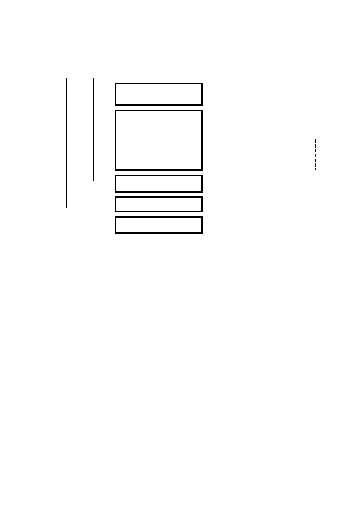
DAG 20 00 – H – DP – P – R
P: Peak measurement function
R: Rank extension function
External I/O
one: standard
DP: Digimatic output
DC: Judgment output
BC: BCD output
※ Note
Cannot select both [-DC] and [-BC]
H: High precision measurement
Type number
Basic model number
DAG
10.2 Optional
(1) Basic accessories
① High precision measurement Measurement range 10µm
② Digimatic output Output to printer (DP-1) ※with cable
③ Judgment output 5 rank (-NG, -OK, OK, +OK, +NG) output (with DC I/O
base extension, connector)
Individual output is up to 16 ranks, 17 ranks and or more is code
output.
④ Rank extension function Capable of judging up to maximum of 99 ranks (OK range)
⑤ BCD output Code output of BCD data (with DC I/O base extension,
connector)
⑥ Peak measurement function Measurement value change (+PEAK, -PEAK,
TIR(=(+PEAK)-(-PEAK)), TIR/2(=(+PEAK)-(-PEAK))/2) can be
obtained.
(2) Sold separately
① Filter (DAG2000-0P-AF) Air filter + mist separator
② Filter (DAG2000-0P-AFA) Air filter + mist separator
(with auto drain)
③ Regulator (DAG2000-0P-AR) Precision regulator
④ Serial communications cable (DAG2000-0P-CB-1) D-sub 9 pin connector (EIA-232) for PC
※with sample software
(DAG2000-0P-CB-2) D-sub25 pin connector (EIA-574) for PC
(DAG2000-0P-CB-3) D-sub25 pin connector (EIA-574) for
printer
⑤ Compressed air purifier (DAG2000-0P-HAF) High moisture and oil removal rate
⑥ Foot switch (DAG2000-0P-FSW-1) Single type
(DAG2000-0P-FSW-2) 2 consecutive type
31
Page 32
DIGITAL AIR MICROMETER USERS MANUAL (Second Edition)
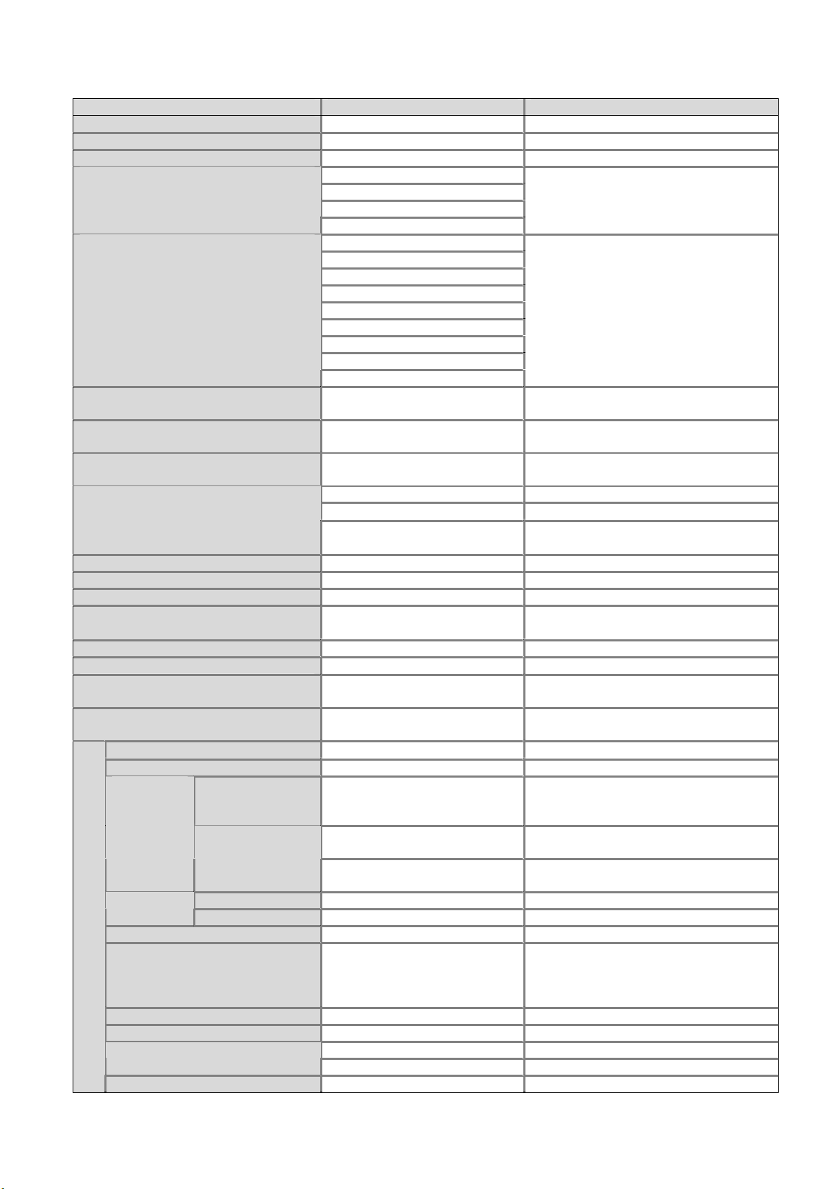
10.3 Specifications
ITEM SPECIFICATIONS REMARKS
Input module Air 1 Channel Built-in AE2000 multi
No. of measurement items 1
No. of programs 10 PROG 1~10
Measurement range
[unit: µm]
100
50
20
10
Display resolution
[unit: µm]
5
2
1
0.5
0.2
0.1
0.05
0.02
0.01
Main display
(Display color)
(Red, green, orange, light dark)
4 digits
Multi-function display 40DOT/F.S. Measurement value is displayed in analog
Automatic master calibration 8 digits (Red) Judgment result, settings values (English,
Automatic master range
Small range, large range
ZERO correction
Sensitivity correction
Electric voltage AC85~264V Attached cable for AC100V
Frequency 50/60Hz common
Electric capacity 30VA
Dimension (L X W X H)
120 x 180 x 150 During fitting of regulator
[unit: µm]
Weight 2.2kg 2.8kg (with regulator)
Operating temperature
Push button input
0~45°C
4 points Measurement command, RESET, master
Foot switch
Serial communications RS232C 1 port Output of measurement value and
High precision measurement
Measurement range 10µm
Digimatic output 1 port Attached DP-1 connection cable
Judgment
output
BCD output
Input signal
8 points
Output signal
Open corrector
24 points
Measurement command, Reset
Master calibration
Program switching
READY
Master OK
1. Rank output
2. BCD output
Single type Measurement command Foot switch
2 consecutive type Measurement command, RESET
Serial communications cable For RS232C
Optional
Peak measurement function +PEAK, -PEAK,
TIR(=+PEAK-(-PEAK)),
TIR/2,
(+PEAK+(-PEAK)/2
Rank extension function 99 ranks maximum OK range
Regulator Precision regulator
Filter
Compressed air purifier When there is too much moisture and oil
Set to each program
10µm range is optional
Set to each program
Can be selected except when range is 100
Can be selected when range is 10, 20
Can only be selected when range is 10
Measurement value, judgment result
dots
numbers)
Within ±50% of measurement range
Within ±50% of measurement range
And within 0.5 ~ 2.0X
300 (depth) mm
calibration (2)
judgment result
Common signal at 1, 2
1, 2 or either one
Based on measurement value change
With auto measurement function
32
Page 33
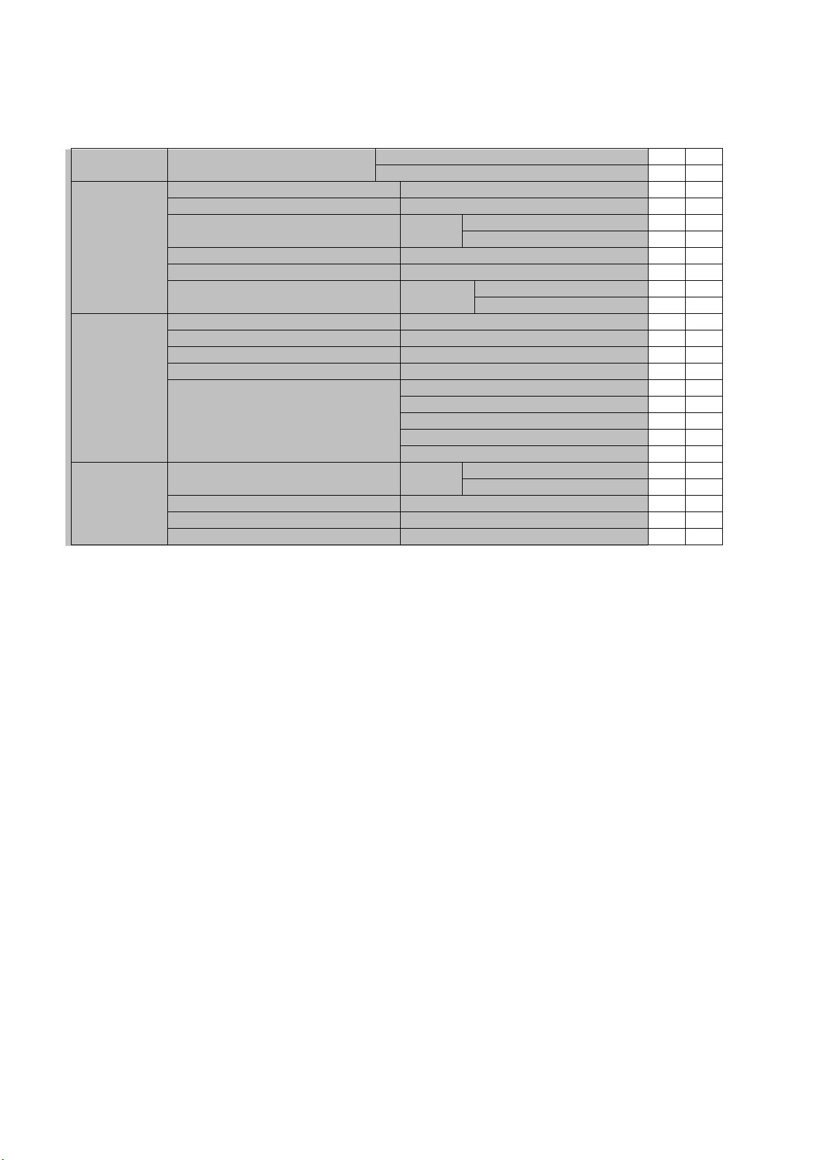
CHAPTER 11 WORKSHEET
Production No.:
DIGITAL AIR MICROMETER USERS MANUAL (Second Edition)
name
Details ▼▲
Normal ▼
System ▲
Settings item name
Model name Settings mode
Program No. [1] [2]
Measurement range RANGE
Display resolution RESOLUTION
+Polarity POL
Sensitivity rough adjustment value GAIN (10~225)
Sensitivity fine adjustment constant CONSTANT (0.100~9.999)
Master calibration method CalMode
MIN & MAX
ZERO M.
Small range master value MIN M. (input the actual dimensions)
Large range master value MAX M. (ditto)
ZERO master value ZERO M. (ditto)
Machine difference correction CORRECT (-0.9999~+0.9999)
Judgment limit values
-NG (input the actual dimensions)
-OK (ditto)
OK (ditto)
+OK (ditto)
+NG (ditto)
HOLDExternal switch operation EXT
SW
NOT HOLD
Moving average frequency SMOOTH (1~30)
Main display MainDisp
English display CharDisp
33
Test Equipment Depot - 800.517.8431 - 99 Washington Street Melrose, MA 02176
TestEquipmentDepot.com
 Loading...