

Nidec Unidrive M700, Unidrive M702, Unidrive M201, Unidrive M300, Unidrive M400 User Manual
...
User Guide
SI-Ethernet and
Unidrive M -
Onboard Ethernet
Part Number: 0478-0137-03
Issue: 3
Original Instructions
For the purposes of compliance with the EU Machinery Directive 2006/42/EC, the English version of this manual
is the Original Instructions. Manuals in other languages are Translations of the Original Instructions.
Documentation
Manuals are available to download from the following locations: http://www.drive-setup.com/ctdownloads
The information contained in this manual is believed to be correct at the time of printing and does not form part of
any contract. The manufacturer reserves the right to change the specification of the product and its performance,
and the contents of the manual, without notice.
Warranty and Liability
In no event and under no circumstances shall the manufacturer be liable for damages and failures due to misuse,
abuse, improper installation, or abnormal conditions of temperature, dust, or corrosion, or failures due to
operation outside the published ratings. The manufacturer is not liable for consequential and incidental damages.
Contact the supplier of the drive for full details of the warranty terms.
Environmental policy
Control Techniques Ltd operates an Environmental Management System (EMS) that conforms to the
International Standard ISO 14001.
Further information on our Environmental Policy can be found at: http://www.drive-setup.com/environment
Restriction of Hazardous Substances (RoHS)
The products covered by this manual comply with European and International regulations on the Restriction of Hazardous Substances including EU directive 2011/65/EU and the Chinese Administrative Measures for Restriction of
Hazardous Substances in Electrical and Electronic Products.
Disposal and Recycling (WEEE)
When electronic products reach the end of their useful life, they must not be disposed of along
with domestic waste but should be recycled by a specialist recycler of electronic equipment.
Control Techniques products are designed to be easily dismantled into their major component
parts for efficient recycling. The majority of materials used in the product are suitable for
recycling.
Product packaging is of good quality and can be re-used. Large products are packed in wooden
crates. Smaller products are packaged in strong cardboard cartons which have a high recycled
fibre content. Cartons can be re-used and recycled. Polythene, used in protective film and bags
for wrapping the product, can be recycled. When preparing to recycle or dispose of any product
or packaging, please observe local legislation and best practice.
REACH legislation
EC Regulation 1907/2006 on the Registration, Evaluation, Authorisation and restriction of Chemicals (REACH)
requires the supplier of an article to inform the recipient if it contains more than a specified proportion of any
substance which is considered by the European Chemicals Agency (ECHA) to be a Substance of Very High
Concern (SVHC) and is therefore listed by them as a candidate for compulsory authorisation.
Further information on our compliance with REACH can be found at: http://www.drive-setup.com/reach
Registered Office
Nidec Control Techniques Ltd
The Gro
Newtown
Powys
SY16 3BE
UK
Registered in England and Wales. Company Reg. No. 01236886.

Copyright
The contents of this publication are believed to be correct at the time of printing. In the interests of a commitment
to a policy of continuous development and improvement, the manufacturer reserves the right to change the
specification of the product or its performance, or the contents of the guide, without notice.
All rights reserved. No parts of this guide may be reproduced or transmitted in any form or by any means,
electrical or mechanical including photocopying, recording or by an information storage or retrieval system,
without permission in writing from the publisher.
Copyright © January 2018 Nidec Control Techniques Ltd

Contents
1 Safety information ..........................................................6
1.1 Warnings, cautions and notes ................................................................. 6
1.2 Important safety information. Hazards.
1.3 Responsibility ..........................................................................................6
1.4 Compliance with regulations ...................................................................6
1.5 Electrical hazards .................................................................................... 7
1.6 Stored electrical charge ...........................................................................7
1.7 Mechanical hazards ................................................................................7
1.8 Access to equipment ............................................................................... 7
1.9 Environmental limits ................................................................................7
1.10 Hazardous environments ........................................................................8
1.11 Motor .......................................................................................................8
1.12 Mechanical brake control ........................................................................8
1.13 Adjusting parameters ..............................................................................8
1.14 Electromagnetic compatibility (EMC) ......................................................8
2 Introduction ....................................................................9
2.1 Products covered by this User Guide ......................................................9
2.2 Features ..................................................................................................9
2.3 Option module identification .................................................................. 10
2.4 Factory fit Ethernet interface identification ............................................11
2.5 Product conformance ............................................................................11
2.6 Conventions used in this guide .............................................................11
2.7 Firmware Statement .............................................................................. 11
3 Mechanical installation ................................................12
4 Electrical installation ...................................................14
4.1 SI-Ethernet module information .............................................................14
4.2 Cabling considerations ..........................................................................14
4.3 Module grounding ..................................................................................14
4.4 Cable shield connections ......................................................................15
4.5 Cable .....................................................................................................15
4.6 Maximum network length ......................................................................15
4.7 Network topology ...................................................................................15
5 Getting started ..............................................................17
5.1 Network design considerations .............................................................17
5.2 Addressing ............................................................................................17
5.3 Where do IP addresses come from? .....................................................17
5.4 Addressing etiquette ..............................................................................17
5.5 Class types ............................................................................................18
5.6 Generating the complete address .........................................................18
5.7 DHCP considerations ............................................................................ 19
5.8 Basic principles of routing .....................................................................20
5.9 Set-up flow chart ...................................................................................21
5.10 Single line parameter descriptions ........................................................22
Competence of designers and installers .................................................6
4 SI-Ethernet User Guide
Issue Number: 3

6 Parameters .................................................................... 36
6.1 Full parameter descriptions ................................................................... 36
7 Key features and Protocols .......................................135
7.1 PC/PLC considerations .......................................................................135
7.2 Modbus TCP/IP ................................................................................... 135
7.3 RTMoE (Real Time Motion over Ethernet) ..........................................144
7.4 Non-cyclic data access ........................................................................153
7.5 EtherNet/IP ..........................................................................................158
7.6 Web page basics .................................................................................191
8 PC Tools Applications ...............................................198
8.1 Unidrive M Connect .............................................................................198
8.2 Machine Control Studio ....................................................................... 198
8.3 CTScope .............................................................................................199
8.4 SyPTPro ..............................................................................................199
8.5 CT OPC server ....................................................................................200
9 Security .......................................................................201
9.1 Introduction ..........................................................................................201
9.2 General site security issues ................................................................201
9.3 Default restrictions ...............................................................................201
10 Diagnostics .................................................................202
10.1 LED diagnostics ..................................................................................202
10.2 Drive trip display codes .......................................................................202
10.3 Ethernet sub trip codes .......................................................................203
10.4 Ethernet sub trip codes .......................................................................205
10.5 Ethernet hardware fault trip codes ......................................................205
10.6 Diagnostic flow chart ...........................................................................206
11 Glossary of terms .......................................................207
SI-Ethernet User Guide 5
Issue Number: 3

1 Safety information
WARNING
CAUT ION
NOTE
1.1 Warnings, cautions and notes
A Warning contains information, which is essential for avoiding a safety hazard.
A Caution contains information, which is necessary for avoiding a risk of damage to the
product or other equipment.
A Note contains information, which helps to ensure correct operation of the product.
1.2 Important safety information. Hazards. Competence of designers and installers
This guide applies to products which control electric motors either directly (drives) or indirectly
(controllers, option modules and other auxiliary equipment and accessories). In all cases the
hazards associated with powerful electrical drives are present, and all safety information relating to
drives and associated equipment must be observed.
Specific warnings are given at the relevant places in this guide.
Drives and controllers are intended as components for professional incorporation into complete
systems. If installed incorrectly they may present a safety hazard. The drive uses high voltages and
currents, carries a high level of stored electrical energy, and is used to control equipment which can
cause injury. Close attention is required to the electrical installation and the system design to avoid
hazards either in normal operation or in the event of equipment malfunction. System design,
installation, commissioning/start-up and maintenance must be carried out by personnel who have
the necessary training and competence. They must read this safety information and this guide
carefully.
1.3 Responsibility
It is the responsibility of the installer to ensure that the equipment is installed correctly with regard
to all instructions given in this guide. They must give due consideration to the safety of the complete
system, so as to avoid the risk of injury both in normal operation and in the event of a fault or of
reasonably foreseeable misuse.
The manufacturer accepts no liability for any consequences resulting from inappropriate, negligent
or incorrect installation of the equipment.
1.4 Compliance with regulations
The installer is responsible for complying with all relevant regulations, such as national wiring
regulations, accident prevention regulations and electromagnetic compatibility (EMC) regulations.
Particular attention must be given to the cross-sectional areas of conductors, the selection of fuses
or other protection, and protective ground (earth) connections.
This guide contains instructions for achieving compliance with specific EMC standards.
All machinery to be supplied within the European Union in which this product is used must comply
with the following directives:
2006/42/EC Safety of machinery.
2014/30/EU: Electromagnetic Compatibility.
6 SI-Ethernet User Guide
Issue: 3

1.5 Electrical hazards
The voltages used in the drive can cause severe electrical shock and/or burns, and could be lethal.
Extreme care is necessary at all times when working with or adjacent to the drive. Hazardous
voltage may be present in any of the following locations:
• AC and DC supply cables and connections
• Output cables and connections
• Many internal parts of the drive, and external option units
Unless otherwise indicated, control terminals are single insulated and must not be touched.
The supply must be disconnected by an approved electrical isolation device before gaining access
to the electrical connections.
The STOP and Safe Torque Off functions of the drive do not isolate dangerous voltages from the
output of the drive or from any external option unit.
The drive must be installed in accordance with the instructions given in this guide. Failure to
observe the instructions could result in a fire hazard.
information
Safety
Introduction
Mechanical
installation
installation
Electrical
1.6 Stored electrical charge
The drive contains capacitors that remain charged to a potentially lethal voltage after the AC supply
has been disconnected. If the drive has been energized, the AC supply must be isolated at least
ten minutes before work may continue.
1.7 Mechanical hazards
Careful consideration must be given to the functions of the drive or controller which might result in a
hazard, either through their intended behaviour or through incorrect operation due to a fault. In any
application where a malfunction of the drive or its control system could lead to or allow damage,
loss or injury, a risk analysis must be carried out, and where necessary, further measures taken to
reduce the risk - for example, an over-speed protection device in case of failure of the speed
control, or a fail-safe mechanical brake in case of loss of motor braking.
With the sole exception of the Safe Torque Off function, none of the drive functions must be
used to ensure safety of personnel, i.e. they must not be used for safety-related functions.
The Safe Torque Off function may be used in a safety-related application. The system designer is
responsible for ensuring that the complete system is safe and designed correctly according to the
relevant safety standards.
The design of safety-related control systems must only be done by personnel with the required
training and experience. The Safe Torque Off function will only ensure the safety of a machine if it is
correctly incorporated into a complete safety system. The system must be subject to a risk
assessment to confirm that the residual risk of an unsafe event is at an acceptable level for the
application.
1.8 Access to equipment
Access must be restricted to authorized personnel only. Safety regulations which apply at the place
of use must be complied with.
1.9 Environmental limits
Instructions in this guide regarding transport, storage, installation and use of the equipment must
be complied with, including the specified environmental limits. This includes temperature, humidity,
contamination, shock and vibration. Drives must not be subjected to excessive physical force.
Getting started Parameters
Key features and
Protocols
Applications
PC Tools
Security Diagnostics
Glossary of
terms
Index
SI-Ethernet User Guide 7
Issue: 3

1.10 Hazardous environments
The equipment must not be installed in a hazardous environment (i.e. a potentially explosive
environment).
1.11 Motor
The safety of the motor under variable speed conditions must be ensured.
To avoid the risk of physical injury, do not exceed the maximum specified speed of the motor.
Low speeds may cause the motor to overheat because the cooling fan becomes less effective,
causing a fire hazard. The motor should be installed with a protection thermistor. If necessary, an
electric forced vent fan should be used.
The values of the motor parameters set in the drive affect the protection of the motor. The default
values in the drive must not be relied upon. It is essential that the correct value is entered in the
Motor Rated Current parameter.
1.12 Mechanical brake control
Any brake control functions are provided to allow well co-ordinated operation of an external brake
with the drive. While both hardware and software are designed to high standards of quality and
robustness, they are not intended for use as safety functions, i.e. where a fault or failure would
result in a risk of injury. In any application where the incorrect operation of the brake release
mechanism could result in injury, independent protection devices of proven integrity must also be
incorporated.
1.13 Adjusting parameters
Some parameters have a profound effect on the operation of the drive. They must not be altered
without careful consideration of the impact on the controlled system. Measures must be taken to
prevent unwanted changes due to error or tampering.
1.14 Electromagnetic compatibility (EMC)
Installation instructions for a range of EMC environments are provided in the relevant Power
Installation Guide. If the installation is poorly designed or other equipment does not comply with
suitable standards for EMC, the product might cause or suffer from disturbance due to
electromagnetic interaction with other equipment. It is the responsibility of the installer to ensure
that the equipment or system into which the product is incorporated complies with the relevant EMC
legislation in the place of use.
8 SI-Ethernet User Guide
Issue: 3

2 Introduction
information
Safety
2.1 Products covered by this User Guide
This User Guide covers the SI-Ethernet option module and the onboard factory installed Ethernet
interface. Both the SI-Ethernet module and the onboard Ethernet interface offer the same
functionality.
The onboard Ethernet interface provides Ethernet connectivity and is installed during manufacture
to the following drives:
• Unidrive M700
• Unidrive M702
The SI-Ethernet is an option module that provides Ethernet connectivity and can be installed to the
following drives:
• Unidrive M200 / M201 (sizes 2 to 9)
• Unidrive M300 (sizes 2 to 9)
• Unidrive M400 (sizes 2 to 9)
• Unidrive M600 (sizes 3 to 11)
• Unidrive M700 / M701 / M702 (sizes 3 to 11)
2.2 Features
The following list gives an overview of the functionality available:
• Single RJ45 connectivity with support for shielded twisted pair.
• 100 Mbs Ethernet with auto-negotiation.
• Full and half duplex operation with auto-negotiation.
• Auto crossover detection.
• TCP/IP.
• Modbus TCP/IP.
• EtherNet/IP.
• Switch or Gateway mode.
• VLAN tagging.
• SyPTPro over Ethernet.
• Unidrive M Connect over Ethernet.
• Machine Control Studio.
• Static IP configuration or DHCP client.
• Non-cyclic data transfer with user program.
• Up to 3 transmit and 3 receive cyclic links (easy mode).
• IEEE1588 Precision Time Protocol synchronization.
• RTMoE (Real Time Motion over Ethernet).
2.2.1 Backup/auxiliary supply
Some drives provide a method of powering up the control circuits (and therefore any option module
installed) if the AC supply is removed, this allows Ethernet communication to continue operating
when the main AC supply is switched off.
Introduction
Mechanical
installation
installation
Electrical
Getting started Parameters
Key features and
Protocols
Applications
PC Tools
Security Diagnostics
Glossary of
terms
SI-Ethernet User Guide 9
Issue: 3
Index
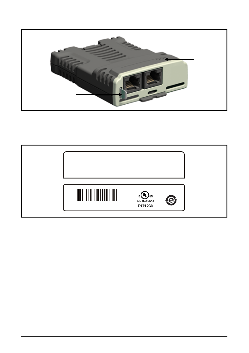
2.3 Option module identification
Earth
connection
Link
LEDs
SI-Ethernet
1714
S/N : 8000001001
S/N : 8000001001
82400000017900
Figure 2-1 SI-Ethernet
The SI-Ethernet can be identified by:
1. The label located on the topside of the option module.
2. The color coding across the front of the option module. SI-Ethernet being beige.
Figure 2-2 SI-Ethernet label
2.3.1 Date code format
The date code is four numbers. The first two numbers indicate the year and the remaining numbers
indicate the week of the year in which the drive was built.
Example:
A date code of 1710 would correspond to week 10 of year 2017.
10 SI-Ethernet User Guide
Issue: 3

2.4 Factory fit Ethernet interface identification
NOTE
As standard, the Unidrive M700 and Unidrive M702 variants are fitted with an Ethernet interface
and the Unidrive M701 is fitted with the EIA-485 serial communications interface.
Care must be taken to ensure the correct interface is fitted before a connection is made to the drive,
failure to ensure this may result in damage to the interface and/or communication device.
The Ethernet and EIA 485 interfaces are similar in appearance but the differences are:
information
Safety
Introduction
• The Ethernet interface will have the Ethernet communication logo on the front of the
panel with the appropriate port number below it. It also has a LED located below each
connector.
• The EIA 485 port just has the number "485" printed alongside it.
2.5 Product conformance
The Ethernet interface complies with IEEE 802.3 and meets the isolation requirements of safety
standard EN50178:1998.
2.6 Conventions used in this guide
The configuration of the host drive and option module is done using menus and parameters. A
menu is a logical collection of parameters that have similar functionality.
In the case of an option module, the option module set-up parameters in menu 0 will appear in
drive menu 15, 16 or 17 depending on which slot the module is installed in. In the case of the
onboard Ethernet interface, the set-up parameters in menu 0 will appear in drive menu 24.
The setting of the Option Slot Identifiers (Pr 11.056) may change the slot numbering from those
described above. The internal menus of the option module or onboard Ethernet interface will
appear before menu 0 and after menu 41.
For Unidrive M200, M300 and M400 drives, the option module set-up parameters will
appear in menu 15.
The method used to determine the menu or parameter is as follows:
•Pr S.mm.ppp - Where S signifies the option module slot number and mm.ppp signifies the
menu and parameter number respectively.
If the option module slot number is not specified then the parameter reference will be a drive
parameter.
•Pr MM.ppp - Where MM signifies the menu allocated to the option module setup menu and
ppp signifies the parameter number within the set-up menu.
•Pr mm.000 - Signifies parameter number 000 in any drive menu.
Mechanical
installation
installation
Electrical
Getting started Parameters
Key features and
Protocols
Applications
PC Tools
Security Diagnostics
2.7 Firmware Statement
This product is supplied with the latest firmware version. When retro-fitting to an existing system, all
firmware versions should be verified to confirm the same functionality as products of the same type
already present. This also applies to products returned from a Nidec Industrial Automation’s
Service Centre or Repair Centre. If there is any doubt please contact the supplier of the product.
The firmware version of the product can be identified by looking at Pr MM.002 where MM is the
relevant menu number for the module slot being used.
SI-Ethernet User Guide 11
Issue: 3
Glossary of
terms
Index
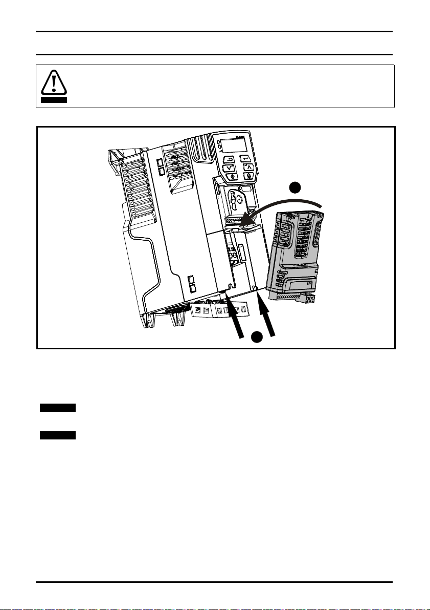
3 Mechanical installation
WARNING
1
2
NOTE
NOTE
Before installing or removing an option module from any drive, ensure the AC supply has
been disconnected for at least 10 minutes and refer to Chapter 1 Safety information on
page 6. If using a DC bus supply ensure this is fully discharged before working on any
drive or option module.
Figure 3-1 Installation of an SI option module on Unidrive M200 to M400 (sizes 2 to 4)
• With the option module tilted slightly backwards, align and locate the two holes in the rear of the
option module onto the two tabs (1) on the drive.
• Place the option module onto the drive as shown in (2) until the module clicks into place. The
terminal cover on the drive holds the option module in place, so this must be put back on.
Option modules can only be installed on drives that have the option module slot
functionality.
Figure 3-1 above is for illustration only, the actual option module may be different to the
one shown.
12 SI-Ethernet User Guide
Issue: 3
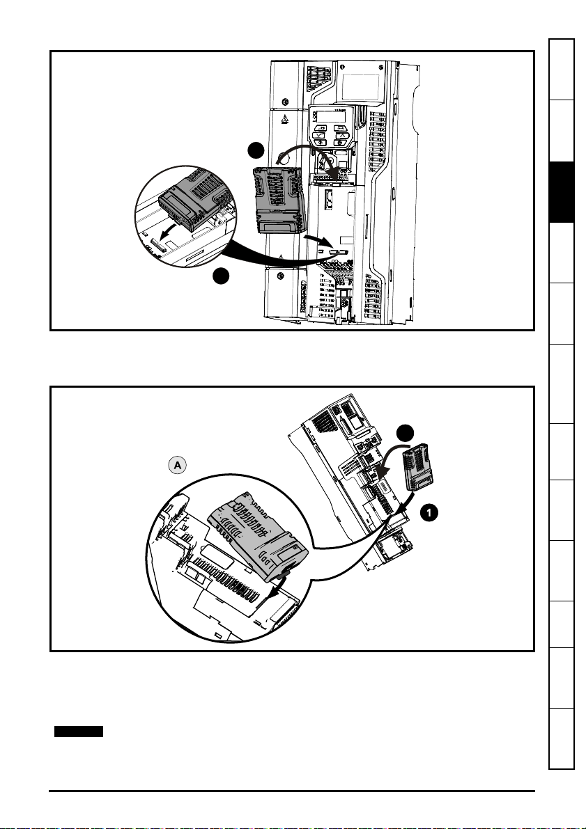
Figure 3-2 Installation of an SI option module on Unidrive M200 to M400 (sizes 5 to 9)
1
2
2
NOTE
• Place the option module onto the drive as shown in (2) until the module clicks into place. The
terminal cover on the drive holds the option module in place, so this must be put back on.
Figure 3-3 Installation of an SI option module on Unidrive M600 to M702
information
Safety
Introduction
Mechanical
installation
installation
Electrical
Getting started Parameters
and Protocols
Key features
• Move the option module in direction shown (1/2).
• Align and insert the option module tab in to the slot provided, this is highlighted in the detailed
view (A).
• Press down on the option module until it clicks into place.
Option module slots must be used in the following order: Slot 3 (lower), Slot 2 (middle)
and then Slot 1(upper).
SI-Ethernet User Guide 13
Issue: 3
Applications
PC Tools
Security Diagnostics
Glossary of
terms
Index

4 Electrical installation
Earth
connection
Link
LEDs
Not used
12345678
Not used
Transmit +
Receive +
Not used
Transmit -
Receive -
Not used
Not used
12345678
Not used
Transmit +
Receive +
Not used
Transmit -
Receive -
Not used
Spade
connector
NOTE
4.1 SI-Ethernet module information
SI-Ethernet provides two standard RJ45 UTP/STP (Un-shielded/Shielded Twisted Pair)
connections to a 100 Mbs Ethernet system. In addition to the RJ45 connectors, a grounding tag is
supplied for supplementary bonding. SI-Ethernet provides 2 diagnostic LEDs for status and
information purposes located on the module topside.
Figure 4-1 SI-Ethernet
Figure 4-1 shows an overview of the module connections and indicators.
Figure 4-2 Ethernet connections
Figure 4-2 shows the electrical connections of the RJ45 connector.
On the onboard Ethernet interface, pin1 is located on the left but on the SI-Ethernet
module pin 1 is located on the right (as shown).
4.2 Cabling considerations
To ensure long-term reliability it is recommended that any cables used to connect a system
together are tested using a suitable Ethernet cable tester, this is of particular importance when
cables are constructed on site.
Any isolated signal circuit has the capability to become live through accidental contact with other
conductors; as such they should always be double-insulated from live parts. The routing of network
and signal wires should be done so as to avoid close proximity to mains voltage cabling.
4.3 Module grounding
SI-Ethernet is supplied with a grounding tag on the module that should be connected to the closest
possible grounding point using the minimum length of cable. This will greatly improve the noise
immunity of the module.
14 SI-Ethernet User Guide
Issue: 3
4.4 Cable shield connections
NOTE
NOTE
Standard Ethernet UTP or STP cables do not require supplementary grounding.
4.5 Cable
It is recommended that a minimum specification of CAT5e is installed on new installations, as this
gives a good cost/performance ratio. If you are using existing cabling, this may limit the maximum
data rate depending on the cable ratings. In noisy environments, the use of STP or fiber optic cable
will offer additional noise immunity.
Cabling issues are the single biggest cause of network down-time. Ensure cabling is
correctly routed, wiring is correct, connectors are correctly installed and any switches or
routers used are rated for industrial use. Office grade Ethernet equipment does not
generally offer the same degree of noise immunity as equipment intended for industrial
use.
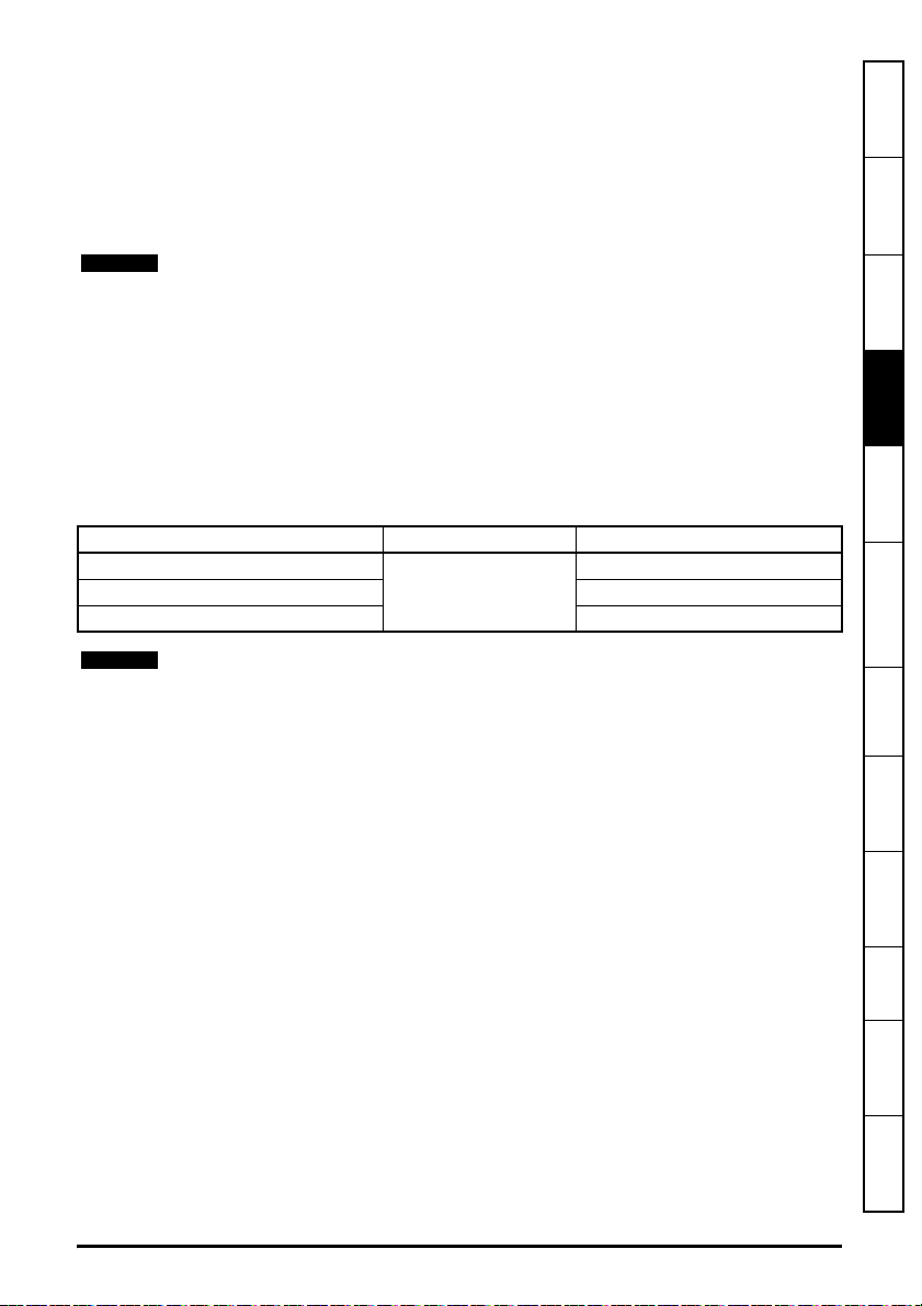
4.6 Maximum network length
The main restriction imposed on Ethernet cabling is the length of a single segment of cable as
detailed in Table 4-1. If distances greater than this are required it may be possible to extend the
network with additional switches or by using a fiber optic converter.
Table 4-1 Ethernet maximum network lengths
Type Of Cable Data rate (bit/s) Maximum trunk length (m)
Copper - UTP/STP CAT 5
Fiber Optic - Multi-mode 3000
100 M
Fiber Optic - Single-mode up to 100000
100
information
Safety
Introduction
Mechanical
installation
installation
Electrical
Getting started Parameters
The distances specified are absolute recommended maximums for reliable transmission
of data. The distances for the fiber optic sections will be dependent on the equipment
used on the network. The use of wireless networking products is not recommended for
control systems, as performance may be affected by many external influences.
4.7 Network topology
The SI-Ethernet option module and onboard Ethernet interface support multiple network topologies
this allows the user to design a robust network using the topology that works best for the chosen
design.
Star topology:
• Enables individual devices to be swapped out
• Minimise message transmission delays
Line topology (daisy chain):
• Simple wiring
• Lowest cost
Tree topology:
• Maximises bandwidth - contains messages within appropriate segments
• Products can be connected in functional groups, e.g. to enable one section of a machine to be
turned off
SI-Ethernet User Guide 15
Issue: 3
and Protocols
Key features
Applications
PC Tools
Security Diagnostics
Glossary of
terms
Index

Figure 4-3 Typical network topologies
16 SI-Ethernet User Guide
Issue: 3

5 Getting started
NOTE
information
Safety
5.1 Network design considerations
Ethernet is an open system allowing many different vendors to design and supply equipment.
When designing an industrial network you must carefully consider the topology and data traffic on
the network to avoid potential problems.
To avoid bandwidth issues it is recommended that the control network is logically separate from any
other network. Where possible a physically separate network should be used. If this is not possible,
the use of managed network devices should be considered to prevent unnecessary traffic such as
broadcasts reaching the control network.
The use of un-switched hubs is not supported.
5.2 Addressing
The addressing system used on Ethernet uses two essential numbers for making connection, these
are the IP address and the subnet mask. The address allows a specific device to be located and
the subnet mask defines how many bits represent the subnet part of the address and how many
bits represent the node address (see section 5.6.1 The IP address on page 19). Generally devices
on different subnets can only communicate by using a gateway (typically a router or firewall).
5.3 Where do IP addresses come from?
Every address on a network must be unique. If you do not connect your network to any other
networks the assignment of IP addresses is not critical (although using a standard system is
recommended), as you have full control of the addresses used. The issue of addressing becomes
important when connecting multiple networks together or connecting to the Internet where there is
a strong possibility of duplication of addresses if a scheme is not followed.
5.4 Addressing etiquette
The following list details some points that should be considered when selecting addresses:
• Reserve address space: Ensure you have enough reserve address space on your chosen
addressing scheme to allow for future expansion.
• Uniqueness: Ensure your addresses are unique, every device on a subnet must have a
unique address.
• Avoid reserved addresses: For example the address 127.0.0.1 is reserved as the loop back
address.
• Broadcast and system addresses: The highest and lowest host address on a subnet are
reserved addresses.
• Use a system: Have a scheme for assigning your addresses, for example typically servers
may have a low IP address and routers a high IP address. It is not necessary to allocate
consecutive IP addresses so it is possible to reserve ranges for specific uses such as servers,
work stations or routers.
Introduction
Mechanical
installation
installation
Electrical
Getting started
Parameters
and Protocols
Key features
Applications
PC Tools
Security Diagnostics
SI-Ethernet User Guide 17
Issue: 3
Glossary of
terms
Index

5.5 Class types
NOTE
IP addresses are grouped into ranges called classes, each class has a specific set of addresses
and has a typical situation where it is used.
When selecting the class of IP address required, consideration must be given to how many subnets
you need, how many hosts are required and if you will need a public (worldwide) or a private (local)
addressing scheme. Table 5-1 shows an overview of how the class types are defined and Table 5-2
shows how each class separates the subnet and host ID.
Table 5-1 Subnets and hosts supported by class type
Address Class First Octet Decimal
Range
A 1-126.x.y.z 126 16,777,214
B 128-191.x.y.z 16,382 65,534
C 192-223.x.y.z 2,097,150 254
Table 5-2 Address components
Address Class IP Address Subnet Component Host Component
A w.x.y.z w x.y.z
B w.x.y.z w.x y.z
C w.x.y.z w.x.y z
Using the subnet mask it is possible to modify the IP addressing such that the ratio of
subnets and host addresses may be changed. This gives you the facility to “adjust”
standard classes to suit your specific requirements.
5.5.1 Class A addresses
A class A address only uses the first octet to represent the subnet, the remaining octets are used to
represent the host id. These addresses are intended for large organisations such as universities
and the military. These addresses must be requested from the governing body (InterNIC) when
using them publicly (on the Internet) to avoid duplication.
5.5.2 Class B addresses
A class B address uses the first two octets to represent the subnet, the remaining octets are used to
represent the host id. These addresses are intended for medium to large size networks. These
addresses must be requested from the governing body (InterNIC) when using them publicly (on the
Internet) to avoid duplication. Class B addresses are generally used on public or private networks.
Number of
Subnets
Number of Hosts
5.5.3 Class C addresses
Class C addresses use the first 3 octets as the subnet address and the remaining octet as the host
id. A class C address is normally used on a private network only, due to the restriction on the
number of hosts on the network. Class C addresses will not be routed onto the Internet.
5.5.4 Class D & E addresses
These addresses are reserved for multicasting and experimental use.
5.6 Generating the complete address
A complete IP address consists of an IP address and a subnet mask, these two numbers are
required to allow communication on Ethernet using TCP/IP.
18 SI-Ethernet User Guide
Issue: 3
5.6.1 The IP address
x yw
z
192 168 0
1
x yw
z
255 255
255
0
x yw
z
192 168 0
0
IP Address
Subnet Mask
Subnet Address
Host
Address
bit-
wise AND
NOTE
The IP address is made up from four 8 bit decimal numbers (octets) and is written as follows:
w.x.y.z for example192.168.0.1 (class c)
information
Safety
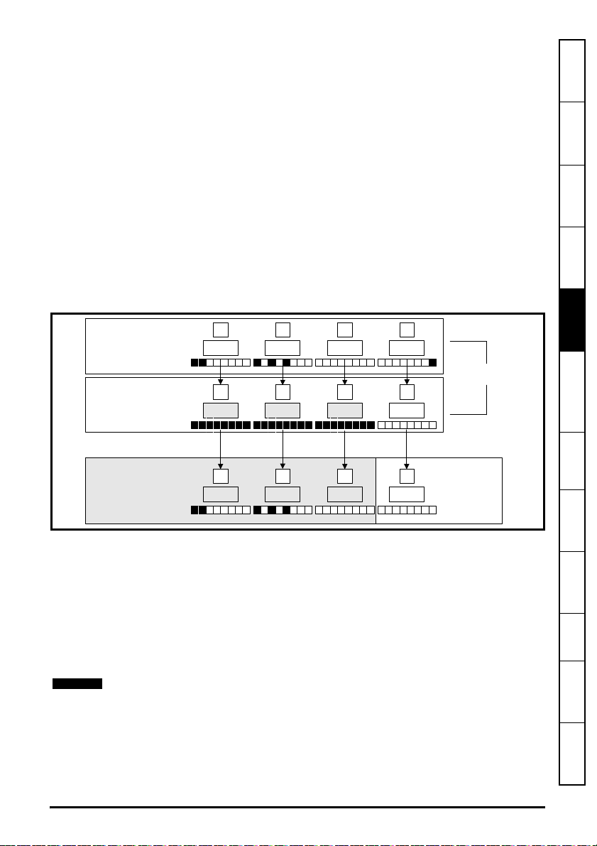
5.6.2 The subnet mask
The subnet mask defines what part of the address constitutes the subnet within the IP address and
what part of the address constitutes the host address. The subnet mask is bit-wise ANDed with the
address to give the subnet to which the host belongs. A typical class C subnet mask would be
255.255.255.0, this may alternatively be written as ‘/24’ as in the example below, showing an IP
address of 192.168.0.1 with a subnet mask of 255.255.255.0. This alternative notation indicates the
number of bits representing the subnet part of the address, starting from the most significant bit.
Alternative subnet mask notation: 192.168.0.1 /24
5.6.3 Completing the address
To determine which part of the address constitutes the network address and which part constitutes
the node address, the IP address is bit-wise ANDed with the subnet mask. Figure 5-1 shows how
the IP address and subnet mask are used to determine the subnet address and the host address.
Figure 5-1 Completing the address
Introduction
Mechanical
installation
installation
Electrical
Getting started
Parameters
and Protocols
Key features
Applications
PC Tools
5.7 DHCP considerations
5.7.1 Using fixed IP addressing
Using fixed IP addresses (manually configured) means that if a module fails, the IP address can be
restored to a replacement module without the need to reconfigure the DHCP server. Using fixed
addresses also prevents the DHCP server from changing the address. When using fixed IP
addresses, it is vital that the IP address is reserved on the DHCP server to prevent duplicate
addressing.
If using manual IP address configuration please note that the IP address subnet mask
and the default gateway must also be set manually. For more information on manual
configuration see section 7.2.6 Network on page 22.
SI-Ethernet User Guide 19
Issue: 3
Security Diagnostics
Glossary of
terms
Index

5.7.2 Using DHCP
NOTE
If DHCP is used, it is recommended that the allocated IP address is bound to the MAC address of
the Ethernet interface, this strategy prevents the IP address changing on the Ethernet interface.
Any leased addresses should be leased permanently to prevent IP address changes.
If the SI-Ethernet module is configured to use DHCP and the module requires
exchanging, the new SI-Ethernet module will have a different MAC address and hence
the DHCP server will issue the new module with a different IP address.
5.8 Basic principles of routing
Routing is required to get TCP/IP packets from one subnet to another. In an IP network, nodes from
one subnet cannot communicate directly with nodes on a different subnet. To allow nodes to
communicate, a router (or similar device) is required to allow the two subnets to exchange data.
This means that any node wishing to communicate with a node that is not on its own subnet, must
know the address of a router that is on its own subnet. This is sometimes called a gateway or
default gateway.
20 SI-Ethernet User Guide
Issue: 3

5.9 Set-up flow chart
Start
Connect all drives
together using
approved
cable /
connectors /
switches
Ensure each drive
Is correctly
grounded
Ensure that there
are no circular
loops between
devices/switches
Ensure the correct
cable types are
used
Perform cable
tests
A dedicated
Ethernet cable
tester Is
recommended.
Configure the IP
address, subnet
mask and default
gateway
Ensure PC is on
the same subnet
or the default
gateway on the
drive & PC are set
Ensure segment
lengths no longer
than maximum
limits.
END
See Chapter 4
See Chapter 4
See Chapter 4
See Chapter 4
See Chapter 5
Save module
settings on drive
.
See Chapter 5
Note: Redundant
systems require
specialist hardware.
PING all drives
from a command
prompt to test
connections
See Chapter 5
Any changes
made will require a
module reset to be
activated
Pr
MM.007
= On
information
Safety
Introduction
Mechanical
installation
installation
Electrical
Getting started
Parameters
and Protocols
Key features
Applications
PC Tools
Security Diagnostics
SI-Ethernet User Guide 21
Issue: 3
Glossary of
terms
Index

5.10 Single line parameter descriptions
Table 5-3 lists the coding used for the parameter type in the subsequent parameter description
tables.
Table 5-3 Parameter type coding
RW
Read /
Write
RO Read-only Bit
Bit
parameter
Txt Text string Date
Date
parameter
Time
Time
parameter
Character
Chr
parameter
Number
Num
parameter
FI Filtered US User save PS
Binary
Bin
parameter
DE Destination ND
IP IP address Mac
No default
value
Power-
down save
RA
BU
MAC
address
Rating
dependent
Bit default
or Unipolar
Ver
NC
Versi on
number
Non-
copyable
Slot, menu,
SMP
parameter
PT Protected
5.10.1 Internal menus
The Ethernet interface provides parameters for configuration and information, these parameters
are grouped into menus as shown in Table 5-4
Table 5-4 Ethernet internal menus
Menu Name Description
S.0 Module Setup
S.2 Ethernet Configures and provides information on the Ethernet network
S.9 Resources Provides information on the module task resources and PCB temperature
S.10 Easy Mode Configures and provides information on the Easy Mode cyclic data setup
S.11 Synchronization Configures and provides information on the module synchronization
S.15 Modbus Configures the Modbus protocol features
S.20 EtherNet/IP Configures and provides information on the EtherNet/IP protocol
S.21 EtherNet/IP IN Configures the EtherNet/IP input mappings (PLC to Drive)
S.22 EtherNet/IP OUT Configures the EtherNet/IP output mappings (Drive to PLC)
S.23
EtherNet/IP Fault
Val ues
Provides module information such as firmware version, serial number and
status
Configures the EtherNet/IP values to write under a network loss condition
22 SI-Ethernet User Guide
Issue: 3

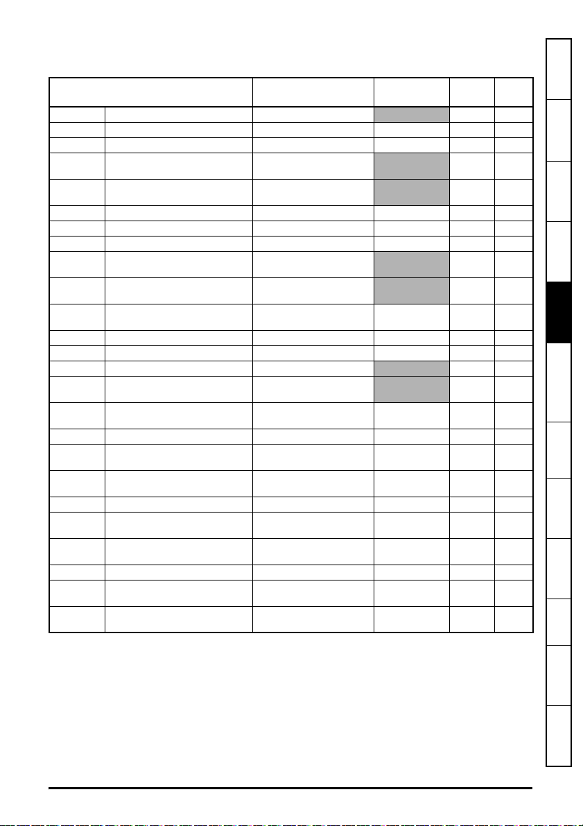
5.10.2 Menu 0 - Ethernet set-up (MM.ppp)
Table 5-5 Menu 0 parameters
Parameter Range Default Access
S.00.000 Parameter mm.000 0 to 65535 RW 16
S.00.001 Module ID 0 to 65535
S.00.002 Software Version
00.00.00.00 to
99.99.99.99
S.00.003 Hardware Version 0.00 to 99.99
S.00.004 Serial Number LS 0 to 99999999
S.00.005 Serial Number MS 0 to 99999999
S.00.006 Status -2 to 3
RO 16
RO 32
RO 16
RO 32
RO 32
RO 8
S.00.007 Reset 0 (Off) to 1 (On) 0 (Off) RW 1
S.00.008 Default 0 (Off) to 1 (On) 0 (Off) RW 1
S.00.009 Active Alarm Bits
S.00.010 Active IP Address
0000000000000000 to
1111111111111111
0.0.0.0 to
255.255.255.255
0000000000000000 RO 16
0.0.0.0 RO 32
S.00.011 Reserved
S.00.054 Reserved
Menu 0 within the SI-Ethernet option module, is also displayed in the drive menu 15, 16 or 17
depending on which slot the option module is installed to and the setting of the Option Slot
Identifiers parameter (S.11.056).
By default, the SI-Ethernet option module will be either menu 15, 16 or 17 and the onboard
Ethernet interface will be menu 24.
Table 5-6 Menu 0 slot availability details the drive models and their available slots and associated
drive menus for use with both the SI-Ethernet option module and the onboard Ethernet interface.
Table 5-6 Menu 0 slot availability
Drive model Module Slot number Drive menu (MM)
115
M200 / M201 / M300 / M400
SI-Ethernet
2 N/A
3 N/A
Onboard Ethernet 4 N/A
115
M600
SI-Ethernet
216
317
Onboard Ethernet 4 N/A
115
M700 / M702
SI-Ethernet
216
317
Onboard Ethernet 4 24
115
M701
SI-Ethernet
216
317
Onboard Ethernet 4 N/A
Size
(Bits)
information
Safety
Introduction
Mechanical
installation
installation
Electrical
Getting started
Parameters
and Protocols
Key features
Applications
PC Tools
Security Diagnostics
Glossary of
terms
Index
SI-Ethernet User Guide 23
Issue: 3

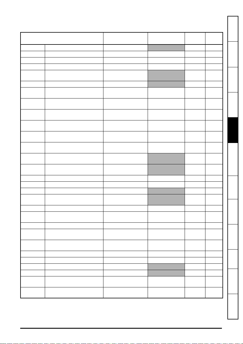
5.10.3 Menu 2 - Ethernet Configuration
Table 5-7 Menu 2 parameters
Parameter Range Default Access
S.02.000 Parameter mm.000 0 to 65535 RW 16
S.02.003 Network Status 0 to 5
S.02.004 Network Message Count 0 to 65535 msg/s
S.02.005 DHCP Enable 0 (Off) to 1 (On) 1 (On) RW 1
S.02.006 IP Address
S.02.007 Subnet Mask
S.02.008 Default Gateway
S.02.009 Primary DNS
S.02.010 Secondary DNS
S.02.011 MAC Address
S.02.020 Priority Protocol 0 to 2 0 RW 8
S.02.021 Web Server Enable 0 (Off) to 1 (On) 1 (On) RW 1
S.02.022 Web Server Port 0 to 65535 80 RW 16
S.02.024 Ethernet MTU 158 to 1500 bytes 1500 bytes RW 16
S.02.025 Gateway Mode 0 to 2 0 RW 8
S.02.030 VLAN Enable 0 (Off) to 1 (On) 0 (Off) RW 1
S.02.031 Drive VLAN ID 0 to 255 0 RW 8
S.02.034 Drive Mode
S.02.035 Non cyclic enable 0 (Off) to 1 (On) 0 (Off) RW 1
S.02.036 Non cyclic base parameter
0.0.0.0 to
255.255.255.255
0.0.0.0 to
255.255.255.255
0.0.0.0 to
255.255.255.255
0.0.0.0 to
255.255.255.255
0.0.0.0 to
255.255.255.255
000000000000 to
FFFFFFFFFFFF
0 (Unidrive M) to
1 (Unidrive SP)
0 (0.00.000) to
59999 (0.59.999)
192.168.1.254 RW 32
255.255.255.0 RW 32
192.168.1.254 RW 32
0.0.0.0 RW 32
0.0.0.0 RW 32
0 (Unidrive M) RW 8
0 (0.00.000) RW 16
RO 8
RO 16
RO 64
Size
(Bits)
5.10.4 Menu 9 - Ethernet Resources
Table 5-8 Menu 9 parameters
Parameter Range Default
S.09.000 Parameter mm.000 0 to 65535
S.09.001 Cyclic Tx Links Free 0 to 255
S.09.002 Cyclic Rx Links Free 0 to 255
S.09.003 Fieldbus Links Free 0 to 255
S.09.004 Cyclic Mappings Free 0 to 255
S.09.008
S.09.010 Sync Task % Free 0 to 255 %
S.09.020 Sync Task Worst % Free 0 to 255 %
S.09.030 PCB Temperature
Background cycles per
second
0 to 65535
-128 to 127
o
C
Access Size (Bits)
RW 16
RO 8
RO 8
RO 8
RO 8
RO 16
RO 8
RO 8
RO 8
24 SI-Ethernet User Guide
Issue: 3

5.10.5 Menu 10 - Easy Mode Cyclic Data
Table 5-9 Menu 10 parameters
Parameter Range Default Access
S.10.000 Parameter mm.000 0 to 65535 RW 16
S.10.001 Easy Mode Enable 0 (Off) to 1 (On)
S.10.002 Easy Mode Reset 0 (Off) to 1 (On)
S.10.003 Easy Mode Default 0 (Off) to 1 (On) 0 (Off) RW 1
S.10.004 Cyclic Messages Per Second 0 to 65535 msg/s
S.10.005 Configuration Valid 0 (Off) to 1 (On)
S.10.006 Operational 0 (Off) to 1 (On)
S.10.007 Active Configuration 0 to 2
S.10.008 Timeout Count 0 to 65535
S.10.009 Data Late Count 0 to 65535
S.10.010 Tx1 Link Profile 0 (Std) to 1 (Sync)
S.10.011 Tx1 Link Number 0 to 255
S.10.012 Tx1 Source Parameter
0 (0.00.000) to
499999 (4.99.999)
S.10.013 Tx1 Parameter Count 0 to 10
S.10.014 Tx1 Transmission Type
S.10.015 Tx1 Destination Address
0 (Unicast) to
11 (Multicast10)
0.0.0.0 to
255.255.255.255
S.10.016 Tx1 Message Rate 0 to 100 ms
S.10.019 Tx1 Link Status
-31 (Disabled) to
2 (OK Sync)
S.10.020 Tx2 Link Profile 0 (Std) to 1 (Sync)
S.10.021 Tx2 Link Number 0 to 255
S.10.022 Tx2 Source Parameter
0 (0.00.000) to
499999 (4.99.999)
S.10.023 Tx2 Parameter Count 0 to 10
S.10.024 Tx2 Transmission Type
S.10.025 Tx2 Destination Address
0 (Unicast) to
11 (Multicast10)
0.0.0.0 to
255.255.255.255
S.10.026 Tx2 Message Rate 0 to 100 ms
S.10.029 Tx2 Link Status
-31 (Disabled) to
2 (OK Sync)
S.10.030 Tx3 Link Profile 0 (Std) to 1 (Sync)
S.10.031 Tx3 Link Number 0 to 255
S.10.032 Tx3 Source Parameter
0 (0.00.000) to
499999 (4.99.999)
S.10.033 Tx3 Parameter Count 0 to 10
S.10.034 Tx3 Transmission Type
S.10.035 Tx3 Destination Address
0 (Unicast) to
11 (Multicast10)
0.0.0.0 to
255.255.255.255
S.10.036 Tx3 Message Rate 0 to 100 ms
S.10.039 Tx3 Link Status
-31 (Disabled) to
2 (OK Sync)
1 (On) RW 1
0 (Off) RW 1
RO 16
RO 1
RO 1
RO 8
RO 16
RO 16
0 (Std) RW 8
0RW8
0 (0.00.000) RW 32
0RW8
0 (Unicast) RW 8
0.0.0.0 RW 32
0 ms RW 8
RO 8
0 (Std) RW 8
0RW8
0 (0.00.000) RW 32
0RW8
0 (Unicast) RW 8
0.0.0.0 RW 32
0 ms RW 8
RO 8
0 (Std) RW 8
0RW8
0 (0.00.000) RW 32
0RW8
0 (Unicast) RW 8
0.0.0.0 RW 32
0 ms RW 8
RO 8
Size
(Bits)
information
Safety
Introduction
Mechanical
installation
installation
Electrical
Getting started
Parameters
and Protocols
Key features
Applications
PC Tools
Security Diagnostics
Glossary of
terms
Index
SI-Ethernet User Guide 25
Issue: 3

Parameter Range Default Access
S.10.040 Rx1 Link Profile 0 (Std) to 1 (Sync) 0 (Std) RW 8
S.10.041 Rx1 Link Number 0 to 255
S.10.042 Rx1 Destination Parameter
S.10.043 Rx1 Parameter Count 0 to 10
S.10.044 Rx1 Source Type
S.10.045 Rx1 Timeout 0 to 65535 ms
S.10.046 Rx1 Timeout Action
S.10.047 Rx1 Timeout Event Dest
S.10.048 Rx1 Timeout Event Type
S.10.049 Rx1 Link Status
S.10.050 Rx2 Link Profile 0 (Std) to 1 (Sync)
S.10.051 Rx2 Link Number 0 to 255 0RW8
S.10.052 Rx2 Destination Parameter
S.10.053 Rx2 Parameter Count 0 to 10
S.10.054 Rx2 Source Type
S.10.055 Rx2 Timeout 0 to 65535 ms
S.10.056 Rx2 Timeout Action
S.10.057 Rx2 Timeout Event Dest
S.10.058 Rx2 Timeout Event Type
S.10.059 Rx2 Link Status
S.10.060 Rx3 Link Profile 0 (Std) to 1 (Sync)
S.10.061 Rx3 Link Number 0 to 255
S.10.062 Rx3 Destination Parameter
S.10.063 Rx3 Parameter Count 0 to 10
S.10.064 Rx3 Source Type
S.10.065 Rx3 Timeout 0 to 65535 ms
S.10.066 Rx3 Timeout Action
S.10.067 Rx3 Timeout Event Dest
S.10.068 Rx3 Timeout Event Type
S.10.069 Rx3 Link Status
0 (0.00.000) to
499999 (4.99.999)
0 (Direct) to
11 (Multicast10)
0 (Trip) to
2 (Hold last)
0 (This slot) to
4 (Slot 4)
0 (No Event) to
4 (Event3)
-31 (Disabled) to
2 (OK Sync)
0 (0.00.000) to
499999 (4.99.999)
0 (Direct) to
11 (Multicast10)
0 (Trip) to
2 (Hold last)
0 (This slot) to
4 (Slot 4)
0 (No Event) to
4 (Event3)
-31 (Disabled) to
2 (OK Sync)
0 (0.00.000) to
499999 (4.99.999)
0 (Direct) to
11 (Multicast10)
0 (Trip) to
2 (Hold last)
0 (This slot) to
4 (Slot 4)
0 (No Event) to
4 (Event3)
-31 (Disabled) to
2 (OK Sync)
0RW8
0 (0.00.000) RW 32
0RW8
0 (Direct) RW 8
100 ms RW 16
0 (Trip) RW 8
0 (This slot) RW 8
0 (No Event) RW 8
RO 8
0 (Std) RW 8
0 (0.00.000) RW 32
0RW8
0 (Direct) RW 8
100 ms RW 16
0 (Trip) RW 8
0 (This slot) RW 8
0 (No Event) RW 8
RO 8
0 (Std) RW 8
0RW8
0 (0.00.000) RW 32
0RW8
0 (Direct) RW 8
100 ms RW 16
0 (Trip) RW 8
0 (This slot) RW 8
0 (No Event) RW 8
RO 8
Size
(Bits)
26 SI-Ethernet User Guide
Issue: 3
5.10.6 Menu 11 - Synchronization
Table 5-10 Menu 11 parameters
Parameter Range Default Access
S.11.000 Parameter mm.000 0 to 65535 RW 16
S.11.001 Preferred Sync Master 0 to 4
S.11.002 Master Clock Domain 0 to 3
S.11.005 Grandmaster MAC Address
S.11.006 Sync Jitter From Grandmaster
0000000000000000 to
FFFFFFFFFFFFFFFF
-2147483648 ns to
2147483647 ns
S.11.007 Sync Jitter Threshold 500 to 1000000 ns
S.11.008 Module Sync Flag 0 (Off) to 1 (On)
S.11.009 Inhibit Drive Synchronisation 0 (Off) to 1 (On) 0 (Off) RW 1
S.11.010 PTP Date
S.11.011 PTP Time
S.11.015 PTP Delay Select
00-00-00 to
31-12-99
00:00:00 to
23:59:59
1 (P2P DELAY) to
2 (Off)
S.11.016 PTP Sync Rate -4 to 0 -4 RW 8
S.11.017 In sync window length 2 to 255 s 20 s RW 8
S.11.020 Network Error Count 0 to 4294967295
S.11.022 Interoption Sync Status
S.11.030
Easy Mode Maximum Network
Delay
0 (MASTER) to
2 (INDEPENDENT)
1 to 100 ms 3 ms RW 8
S.11.040 Rx1 Late Sync Frame Action 1 (Trip) to 3 (Use) 1 (Trip) RW 8
S.11.041 Rx1 Late Sync Frame Dest
S.11.042 Rx1 Late Sync Frame Event
0 (This slot) to
4 (Slot 4)
0 (No Event) to
4 (Event3)
S.11.050 Rx2 Late Sync Frame Action 1 (Trip) to 3 (Use) 1 (Trip) RW 8
S.11.051 Rx2 Late Sync Frame Dest
S.11.052 Rx2 Late Sync Frame Event
0 (This slot) to
4 (Slot 4)
0 (No Event) to
4 (Event3)
S.11.060 Rx3 Late Sync Frame Action 1 (Trip) to 3 (Use) 1 (Trip) RW 8
S.11.061 Rx3 Late Sync Frame Dest
S.11.062 Rx3 Late Sync Frame Event
0 (This slot) to
4 (Slot 4)
0 (No Event) to
4 (Event3)
1RW8
0RW8
RO 64
RO 32
1000 ns RW 32
0 (Off) RO 1
RO 32
RO 32
1 (P2P DELAY) RW 8
RO 32
RO 8
0 (This slot) RW 8
0 (No Event) RW 8
0 (This slot) RW 8
0 (No Event) RW 8
0 (This slot) RW 8
0 (No Event) RW 8
Size
(Bits)
information
Safety
Introduction
Mechanical
installation
installation
Electrical
Getting started
Parameters
and Protocols
Key features
Applications
PC Tools
Security Diagnostics
SI-Ethernet User Guide 27
Issue: 3
Glossary of
terms
Index

5.10.7 Menu 15 - Modbus
Table 5-11 Menu 15 parameters
Parameter Range Default Access
S.15.000 Parameter mm.000 0 to 65535 RW 16
S.15.001 Enable 0 (Off) to 1 (On)
S.15.002 Reset 0 (Off) to 1 (On)
S.15.003 Default 0 (Off) to 1 (On) 0 (Off) RW 1
S.15.004 Modbus Config Error
S.15.005 Modbus Listening Port 0 to 65535
S.15.006 Maximum Connections 0 to 4
S.15.007
S.15.008
S.15.009 Modbus Timeout 1 to 10000 ms
S.15.010 Modbus Timeout Action
S.15.011
S.15.012
S.15.013
S.15.020 Priority Connection 1
S.15.021 Priority Connection 2
S.15.022 Priority Connection 3
S.15.023 Priority Connection 4
Maximum Priority
Connections
Max Connections Per
Client
Modbus Timeout Event
Dest
Modbus Timeout Event
Typ e
Modbus Register
Addressing Mode
0 (No error) to
3 (Num Connections)
0 to 5
1 to 4
0 (Trip) to
1 (No action)
0 (This slot) to
4 (Slot 4)
0 (No event) to
5 (Trigger Event 4)
0 (Standard) to
1 (Modified)
0.0.0.0 to
255.255.255.255
0.0.0.0 to
255.255.255.255
0.0.0.0 to
255.255.255.255
0.0.0.0 to
255.255.255.255
1 (On) RW 1
0 (Off) RW 1
RO 8
502 RW 16
2RW8
2RW8
2RW8
100 ms RW 16
1 (No action) RW 8
0 (This slot) RW 8
0 (No event) RW 8
0 (Standard) RW 8
0.0.0.0 RW 32
0.0.0.0 RW 32
0.0.0.0 RW 32
0.0.0.0 RW 32
Size
(Bits)
28 SI-Ethernet User Guide
Issue: 3
5.10.8 Menu 20 - EtherNet/IP Setup
Table 5-12 Menu 20 parameters
Parameter Range Default Access
S.20.000 Parameter mm.000 0 to 65535 RW 16
S.20.001 Enable EtherNet/IP 0 (Off) to 1 (On)
S.20.002 Reset 0 (Off) to 1 (On)
S.20.003 Default 0 (Off) to 1 (On) 0 (Off) RW 1
S.20.004 Configuration error
0 (No error) to
8 (Out cons trig pr)
S.20.007 Cyclic Data Transfers/s 0 to 65535
S.20.011 RPI timeout action
S.20.012 RPI Timeout Event Dest
S.20.013 RPI timeout event type
S.20.015 PLC idle action
S.20.016 PLC idle event destination
S.20.017 PLC idle event type
S.20.018 Active input assembly object
S.20.019 Active output assembly object
0 (Trip) to
4 (No Action)
0 (This slot) to
4 (Slot 4)
0 (No event) to
5 (Trigger Event 4)
0 (Trip) to
4 (No action)
0 (This slot) to
4 (Slot 4)
0 (No event) to
5 (Trigger Event 4)
0 (100-PrimaryI) to
4 (73-ExtSpdTqCtrI)
0 (101-PrimaryO) to
4 (23-ExtSpdTqCtrO)
S.20.020 Input assembly object size 4 to 128 bytes
S.20.021 Output assembly object size 4 to 128 bytes
S.20.024 In Assembly Obj Process Time 0 to 65535 ms
S.20.025
Out Assembly Obj Process
Time
0 to 65535 ms
S.20.026 In Consistency Enable 0 (Off) to 1 (On)
S.20.027 In Consistency Trigger Param
0 (0.00.000) to
499999 (4.99.999)
S.20.028 Out Consistency Enable 0 (Off) to 1 (On)
S.20.029 Out Consistency Trigger Param
S.20.030 Custom Vendor ID
0 (0.00.000) to
499999 (4.99.999)
0 (257–CT) to
1 (553–CT AMERICA)
S.20.031 Custom product code 0 to 65535
S.20.032 Custom product revision code 0 to 65535
S.20.033 Actual Product Code 0 to 65535
S.20.034 Actual Product Revision 0 to 65535
S.20.040 Type of Motor 1
S.20.041 Type of Motor 2
0 (2-FC DC) to
4 (10-Trap PM BL)
0 (2-FC DC) to
4 (10-Trap PM BL)
1 (On) RW 1
0 (Off) RW 1
RO 8
RO 16
3 (Hold last) RW 8
0 (This slot) RW 8
0 (No event) RW 8
4 (No action) RW 8
0 (This slot) RW 8
0 (No event) RW 8
RO 8
RO 8
8 bytes RW 8
8 bytes RW 8
RO 16
RO 16
0 (Off) RW 1
0 (0.00.000) RW 32
0 (Off) RW 1
0 (0.00.000) RW 32
0 (257–CT) RW 8
0RW16
0RW16
RO 16
RO 16
2 (7-SCI) RO 8
2 (7-SCI) RO 8
Size
(Bits)
information
Safety
Introduction
Mechanical
installation
installation
Electrical
Getting started
Parameters
and Protocols
Key features
Applications
PC Tools
Security Diagnostics
Glossary of
terms
Index
SI-Ethernet User Guide 29
Issue: 3

5.10.9 Menu 21 - EtherNet/IP In Mappings
Table 5-13 Menu 21 parameters
Parameter Range Default Access
S.21.000 Parameter mm.000 0 to 65535 RW 16
S.21.001 Input mapping parameter 1
S.21.002 Input mapping parameter 2
S.21.003 Input mapping parameter 3
S.21.004 Input mapping parameter 4
S.21.005 Input mapping parameter 5
S.21.006 Input mapping parameter 6
S.21.007 Input mapping parameter 7
S.21.008 Input mapping parameter 8
S.21.009 Input mapping parameter 9
S.21.010 Input mapping parameter 10
S.21.011 Input mapping parameter 11
S.21.012 Input mapping parameter 12
S.21.013 Input mapping parameter 13
S.21.014 Input mapping parameter 14
S.21.015 Input mapping parameter 15
S.21.016 Input mapping parameter 16
S.21.017 Input mapping parameter 17
S.21.018 Input mapping parameter 18
S.21.019 Input mapping parameter 19
S.21.020 Input mapping parameter 20
S.21.021 Input mapping parameter 21
S.21.022 Input mapping parameter 22
S.21.023 Input mapping parameter 23
S.21.024 Input mapping parameter 24
0 (0.00.000) to
499999 (4.99.999)
0 (0.00.000) to
499999 (4.99.999)
0 (0.00.000) to
499999 (4.99.999)
0 (0.00.000) to
499999 (4.99.999)
0 (0.00.000) to
499999 (4.99.999)
0 (0.00.000) to
499999 (4.99.999)
0 (0.00.000) to
499999 (4.99.999)
0 (0.00.000) to
499999 (4.99.999)
0 (0.00.000) to
499999 (4.99.999)
0 (0.00.000) to
499999 (4.99.999)
0 (0.00.000) to
499999 (4.99.999)
0 (0.00.000) to
499999 (4.99.999)
0 (0.00.000) to
499999 (4.99.999)
0 (0.00.000) to
499999 (4.99.999)
0 (0.00.000) to
499999 (4.99.999)
0 (0.00.000) to
499999 (4.99.999)
0 (0.00.000) to
499999 (4.99.999)
0 (0.00.000) to
499999 (4.99.999)
0 (0.00.000) to
499999 (4.99.999)
0 (0.00.000) to
499999 (4.99.999)
0 (0.00.000) to
499999 (4.99.999)
0 (0.00.000) to
499999 (4.99.999)
0 (0.00.000) to
499999 (4.99.999)
0 (0.00.000) to
499999 (4.99.999)
10040 (0.10.040) RW 32
2001 (0.02.001) RW 32
0 (0.00.000) RW 32
0 (0.00.000) RW 32
0 (0.00.000) RW 32
0 (0.00.000) RW 32
0 (0.00.000) RW 32
0 (0.00.000) RW 32
0 (0.00.000) RW 32
0 (0.00.000) RW 32
0 (0.00.000) RW 32
0 (0.00.000) RW 32
0 (0.00.000) RW 32
0 (0.00.000) RW 32
0 (0.00.000) RW 32
0 (0.00.000) RW 32
0 (0.00.000) RW 32
0 (0.00.000) RW 32
0 (0.00.000) RW 32
0 (0.00.000) RW 32
0 (0.00.000) RW 32
0 (0.00.000) RW 32
0 (0.00.000) RW 32
0 (0.00.000) RW 32
Size
(Bits)
30 SI-Ethernet User Guide
Issue: 3

Parameter Range Default Access
S.21.025 Input mapping parameter 25
S.21.026 Input mapping parameter 26
S.21.027 Input mapping parameter 27
S.21.028 Input mapping parameter 28
S.21.029 Input mapping parameter 29
S.21.030 Input mapping parameter 30
S.21.031 Input mapping parameter 31
S.21.032 Input mapping parameter 32
0 (0.00.000) to
499999 (4.99.999)
0 (0.00.000) to
499999 (4.99.999)
0 (0.00.000) to
499999 (4.99.999)
0 (0.00.000) to
499999 (4.99.999)
0 (0.00.000) to
499999 (4.99.999)
0 (0.00.000) to
499999 (4.99.999)
0 (0.00.000) to
499999 (4.99.999)
0 (0.00.000) to
499999 (4.99.999)
Size
(Bits)
0 (0.00.000) RW 32
0 (0.00.000) RW 32
0 (0.00.000) RW 32
0 (0.00.000) RW 32
0 (0.00.000) RW 32
0 (0.00.000) RW 32
0 (0.00.000) RW 32
0 (0.00.000) RW 32
information
Safety
Introduction
Mechanical
installation
installation
Electrical
Getting started
Parameters
and Protocols
Key features
SI-Ethernet User Guide 31
Issue: 3
Applications
PC Tools
Security Diagnostics
Glossary of
terms
Index

5.10.10 Menu 22 - EtherNet/IP Out Mappings
Table 5-14 Menu 22 parameters
Parameter Range Default Access
S.22.000 Parameter mm.000 0 to 65535 RW 16
S.22.001 Output mapping parameter 1
S.22.002 Output mapping parameter 2
S.22.003 Output mapping parameter 3
S.22.004 Output mapping parameter 4
S.22.005 Output mapping parameter 5
S.22.006 Output mapping parameter 6
S.22.007 Output mapping parameter 7
S.22.008 Output mapping parameter 8
S.22.009 Output mapping parameter 9
S.22.010 Output mapping parameter 10
S.22.011 Output mapping parameter 11
S.22.012 Output mapping parameter 12
S.22.013 Output mapping parameter 13
S.22.014 Output mapping parameter 14
S.22.015 Output mapping parameter 15
S.22.016 Output mapping parameter 16
S.22.017 Output mapping parameter 17
S.22.018 Output mapping parameter 18
S.22.019 Output mapping parameter 19
S.22.020 Output mapping parameter 20
S.22.021 Output mapping parameter 21
S.22.022 Output mapping parameter 22
S.22.023 Output mapping parameter 23
S.22.024 Output mapping parameter 24
0 (0.00.000) to
499999 (4.99.999)
0 (0.00.000) to
499999 (4.99.999)
0 (0.00.000) to
499999 (4.99.999)
0 (0.00.000) to
499999 (4.99.999)
0 (0.00.000) to
499999 (4.99.999)
0 (0.00.000) to
499999 (4.99.999)
0 (0.00.000) to
499999 (4.99.999)
0 (0.00.000) to
499999 (4.99.999)
0 (0.00.000) to
499999 (4.99.999)
0 (0.00.000) to
499999 (4.99.999)
0 (0.00.000) to
499999 (4.99.999)
0 (0.00.000) to
499999 (4.99.999)
0 (0.00.000) to
499999 (4.99.999)
0 (0.00.000) to
499999 (4.99.999)
0 (0.00.000) to
499999 (4.99.999)
0 (0.00.000) to
499999 (4.99.999)
0 (0.00.000) to
499999 (4.99.999)
0 (0.00.000) to
499999 (4.99.999)
0 (0.00.000) to
499999 (4.99.999)
0 (0.00.000) to
499999 (4.99.999)
0 (0.00.000) to
499999 (4.99.999)
0 (0.00.000) to
499999 (4.99.999)
0 (0.00.000) to
499999 (4.99.999)
0 (0.00.000) to
499999 (4.99.999)
6042 (0.06.042) RW 32
1021 (0.01.021) RW 32
0 (0.00.000) RW 32
0 (0.00.000) RW 32
0 (0.00.000) RW 32
0 (0.00.000) RW 32
0 (0.00.000) RW 32
0 (0.00.000) RW 32
0 (0.00.000) RW 32
0 (0.00.000) RW 32
0 (0.00.000) RW 32
0 (0.00.000) RW 32
0 (0.00.000) RW 32
0 (0.00.000) RW 32
0 (0.00.000) RW 32
0 (0.00.000) RW 32
0 (0.00.000) RW 32
0 (0.00.000) RW 32
0 (0.00.000) RW 32
0 (0.00.000) RW 32
0 (0.00.000) RW 32
0 (0.00.000) RW 32
0 (0.00.000) RW 32
0 (0.00.000) RW 32
Size
(Bits)
32 SI-Ethernet User Guide
Issue: 3

Parameter Range Default Access
S.22.025 Output mapping parameter 25
S.22.026 Output mapping parameter 26
S.22.027 Output mapping parameter 27
S.22.028 Output mapping parameter 28
S.22.029 Output mapping parameter 29
S.22.030 Output mapping parameter 30
S.22.031 Output mapping parameter 31
S.22.032 Output mapping parameter 32
0 (0.00.000) to
499999 (4.99.999)
0 (0.00.000) to
499999 (4.99.999)
0 (0.00.000) to
499999 (4.99.999)
0 (0.00.000) to
499999 (4.99.999)
0 (0.00.000) to
499999 (4.99.999)
0 (0.00.000) to
499999 (4.99.999)
0 (0.00.000) to
499999 (4.99.999)
0 (0.00.000) to
499999 (4.99.999)
Size
(Bits)
0 (0.00.000) RW 32
0 (0.00.000) RW 32
0 (0.00.000) RW 32
0 (0.00.000) RW 32
0 (0.00.000) RW 32
0 (0.00.000) RW 32
0 (0.00.000) RW 32
0 (0.00.000) RW 32
information
Safety
Introduction
Mechanical
installation
installation
Electrical
Getting started
Parameters
and Protocols
Key features
SI-Ethernet User Guide 33
Issue: 3
Applications
PC Tools
Security Diagnostics
Glossary of
terms
Index

5.10.11 Menu 23 - EtherNet/IP Fault Values
Table 5-15 Menu 23 parameters
Parameter Range Default Access
S.23.000 Parameter mm.000 0 to 65535 RW 16
S.23.001 Output fault value 1
S.23.002 Output fault value 2
S.23.003 Output fault value 3
S.23.004 Output fault value 4
S.23.005 Output fault value 5
S.23.006 Output fault value 6
S.23.007 Output fault value 7
S.23.008 Output fault value 8
S.23.009 Output fault value 9
S.23.010 Output fault value 10
S.23.011 Output fault value 11
S.23.012 Output fault value 12
S.23.013 Output fault value 13
S.23.014 Output fault value 14
S.23.015 Output fault value 15
S.23.016 Output fault value 16
S.23.017 Output fault value 17
S.23.018 Output fault value 18
S.23.019 Output fault value 19
S.23.020 Output fault value 20
S.23.021 Output fault value 21
S.23.022 Output fault value 22
S.23.023 Output fault value 23
S.23.024 Output fault value 24
-2147483648 to
2147483647
-2147483648 to
2147483647
-2147483648 to
2147483647
-2147483648 to
2147483647
-2147483648 to
2147483647
-2147483648 to
2147483647
-2147483648 to
2147483647
-2147483648 to
2147483647
-2147483648 to
2147483647
-2147483648 to
2147483647
-2147483648 to
2147483647
-2147483648 to
2147483647
-2147483648 to
2147483647
-2147483648 to
2147483647
-2147483648 to
2147483647
-2147483648 to
2147483647
-2147483648 to
2147483647
-2147483648 to
2147483647
-2147483648 to
2147483647
-2147483648 to
2147483647
-2147483648 to
2147483647
-2147483648 to
2147483647
-2147483648 to
2147483647
-2147483648 to
2147483647
0RW32
0RW32
0RW32
0RW32
0RW32
0RW32
0RW32
0RW32
0RW32
0RW32
0RW32
0RW32
0RW32
0RW32
0RW32
0RW32
0RW32
0RW32
0RW32
0RW32
0RW32
0RW32
0RW32
0RW32
Size
(Bits)
34 SI-Ethernet User Guide
Issue: 3

Parameter Range Default Access
S.23.025 Output fault value 25
S.23.026 Output fault value 26
S.23.027 Output fault value 27
S.23.028 Output fault value 28
S.23.029 Output fault value 29
S.23.030 Output fault value 30
S.23.031 Output fault value 31
S.23.032 Output fault value 32
-2147483648 to
2147483647
-2147483648 to
2147483647
-2147483648 to
2147483647
-2147483648 to
2147483647
-2147483648 to
2147483647
-2147483648 to
2147483647
-2147483648 to
2147483647
-2147483648 to
2147483647
Size
(Bits)
information
Safety
0RW32
0RW32
Introduction
0RW32
0RW32
Mechanical
installation
0RW32
0RW32
installation
0RW32
Electrical
0RW32
Getting started
Parameters
and Protocols
Key features
SI-Ethernet User Guide 35
Issue: 3
Applications
PC Tools
Security Diagnostics
Glossary of
terms
Index

6 Parameters
The Ethernet interface holds two parameter databases; the Ethernet interface internal parameter
database and the host drive's parameter database.
The Ethernet interface internal parameters can be accessed from the drive's keypad, a user
program in a MCi200/MCi210 option module, PC Tools applications software or a module in
another slot of the drive. The notation S.mm.ppp is used to access these parameters where S is
the slot number, mm is the menu number and ppp is the parameter number. For example, to
access Pr 02.004 of a MCi210 installed in slot 2 of a drive from a module in slot 3, it will be
accessed using Pr 2.02.004.
The Ethernet interface will also hold a copy of the host drive's database. At power up, if the stored
drive database is different to that of the drive, the Ethernet interface will upload the drive's database
and overwrite the stored database. If the two databases match, the drive's database will not be
uploaded.
A module that is powered up for the first time will not contain a drive database and therefore will
perform a drive database upload.
6.1 Full parameter descriptions
6.1.1 Menu 0 - Module setup
S.00.001 Module ID
Minimum 0 Maximum 65535
Default None Units None
Type 16 Bit Volatile Update Rate Power-up write
Display Format None Decimal Places 0
Coding RO, ND, NC, PT, BU
The Module ID:
• Onboard Ethernet = 430
• SI-Ethernet option module = 433
S.00.002 Software Version
Minimum
Default None Units None
Type 32 Bit Volatile Update Rate Written on module
Display Format Version Number Decimal Places 0
Coding RO, ND, NC, PT
Module firmware version in ww.xx.yy.zz format.
0
(Display 00.00.00.00)
Maximum
99999999
(Display 99.99.99.99)
initialization
36 SI-Ethernet User Guide
Issue: 3

S.00.003 Hardware Version
Minimum 00.00 Maximum 99.99
Default None Units None
Type 16 Bit Volatile Update Rate Written on module
initialization
Display Format None Decimal Places 2
Coding RO, ND, NC, PT
The hardware version of the option module is in the format of xx.yy.
S.00.004 Serial Number LS
Minimum 0 Maximum 99999999
Default None Units None
Type 32 Bit Volatile Update Rate Power-up write
Display Format Lead Zero Pad Decimal Places 0
Coding RO, ND, NC, PT
The module serial number is available as a pair of 32-bit values where Serial Number LS
(S.00.004) provides the least significant 8 decimal digits, and Serial Number MS (S.00.005)
provides the most significant 8 decimal digits. The reconstructed serial number is ((S.00.005 x
100000000) + S.00.004). For example serial number "0001234567898765" would be stored as
S.00.005 = 12345 and S.00.004 = 67898765.
S.00.005 Serial Number MS
Minimum 0 Maximum 99999999
Default None Units None
Type 32 Bit Volatile Update Rate Power-up write
Display Format None Decimal Places 0
Coding RO, ND, NC, PT
See Serial Number LS (S.00.004)
information
Safety
Introduction
Mechanical
installation
installation
Electrical
Getting started
Parameters
and Protocols
Key features
Applications
PC Tools
S.00.006 Status
Minimum
-2
(Display: Bootldr -
Maximum
3
(Display: Error)
Update)
Default None Units None
Type 8 Bit Volatile Update Rate Background
Display Format Text Decimal Places 0
Coding RO, Txt, ND, NC, PT
This parameter displays the current status of the module. All possible values are shown in the table
overleaf.
SI-Ethernet User Guide 37
Issue: 3
Security Diagnostics
Glossary of
terms
Index

Value Text Description
NOTE
-2 Bootldr - Update The bootloader is performing a flash update.
-1 Bootldr - Idle The bootloader is idle.
0 Initializing Module is currently initializing.
1 OK Module has initialized and has found no errors.
2 Config A configuration error has been detected.
3Error
S.00.007 Reset
Minimum 0 (Off) Maximum 1 (On)
Default 0 (Off) Units None
Type 1 Bit Volatile Update Rate
Display Format Bit Decimal Places 0
Coding RW, NC
When set, the Ethernet interface performs a warm reset. When the reset has been executed and
the Ethernet interface is performing it’s initialization routines this parameter will be cleared to zero.
The drive, and any other modules installed to the drive, will not be affected by the reset.
S.00.008 Default
Minimum
Default
Type 1 Bit Volatile Update Rate
Display Format Bit Decimal Places 0
Coding RW, NC
An error has occurred preventing the module from running
correctly.
Read every 200 ms,
Written to 0 on module
initialization.
0
(Display: Off)
0
(Display: Off)
Maximum
Units None
1
(Display: On)
Read every 200 ms, Written
to 0 on module initialization.
If set to “On” when the module is reset, this parameter will cause the Ethernet interface to return to
it’s “Out of box configuration” and any settings changed will be returned to their default values. This
will include any web page customisations, e-mail settings, etc. Following the default the module will
set the parameter to “Off” and the module will reset.
Take care using this parameter as any configuration information will be irretrievably lost!
38 SI-Ethernet User Guide
Issue: 3

S.00.009 Active Alarm Bits
Minimum
Default
0
(Display:0000000000000000)
0
(Display:0000000000000000)
Maximum
Units None
65535
(D isplay :1111111111111111 )
Type 16 Bit Volatile Update Rate Background
Display
Format
Binary
Decimal
Places
0
Coding RO, NC, BU
Bit Alarm
0
User Program
1
eCMP
2 Modbus
3
Ethernet/IP
4
Reserved
5
Filesystem
6
Too Hot
S.00.010 Active IP Address
Minimum
Default
-2147483648
(Display:128.0.0.0)
0
(Display: 0.0.0.0)
Maximum
Units None
2147483647
(Display:127.255.255.255)
Type 32 Bit Volatile Update Rate Background
Display Format IP address Decimal Places 0
Coding RO, NC, PT
The module’s active IP address.
information
Safety
Introduction
Mechanical
installation
installation
Electrical
Getting started
Parameters
and Protocols
Key features
Applications
PC Tools
Security Diagnostics
SI-Ethernet User Guide 39
Issue: 3
Glossary of
terms
Index

6.1.2 Menu 2 - Ethernet configuration
S.02.003 Network Status
Minimum 0
Default None Units None
Type 8 Bit Volatile Update Rate Written every second
Display Format None Decimal Places 0
Coding RO, Txt, ND, NC, PT, BU
Value Text Description
0 Initializing The network interface is being initialized
1
2
3
4 Ready
5 Active The network interface is receiving or transmitting data
This parameter indicates the status of the network that the module is connected to.
S.02.004 Network Message Count
Minimum 0 Maximum 65535
Default None Units Messages/s
Type 16 Bit Volatile Update Rate Written every second
Display Format None Decimal Places 0
Coding RO, ND, NC, PT, BU
This parameter displays the number of frames that the module is transmitting and/or receiving
every second.
Links
Down
DHCP In
Progress
No
Address
(Display: Initializing)
No link connection has been detected on either of the Ethernet ports
The module is attempting to obtain the IP address, subnet mask, default
gateway and DNS server addresses from a DHCP server
The module does not have an IP address - either the user has not provided
one manually or one could not be allocated via DHCP
The network interface has been successfully configured but no data is
being received or transmitted
Maximum 5
(Display:
Active)
S.02.005 DHCP Enable
Minimum
Default
Type 1 Bit User Save Update Rate Background read
Display Format None Decimal Places 0
Coding RW, BU
Controls whether or not the module will attempt to use a Dynamic Host Configuration Protocol
(DHCP) server to obtain the IP address, subnet mask, default gateway and DNS servers.
0
(Display: Off)
1
(Display: On)
Maximum
Units None
1
(Display: On)
40 SI-Ethernet User Guide
Issue: 3

When DHCP is enabled, the following parameters will become read-only immediately (no reset
required):
• IP Address (S.02.006)
• Subnet Mask (S.02.007)
• Default Gateway (S.02.008)
• Primary DNS (S.02.009)
• Secondary DNS (S.02.010)
information
Safety
Introduction
S.02.006 IP Address
Minimum
Default
0
(Display: 0.0.0.0)
3232235876
(Display:192.168.1.100)
Maximum
Units None
4294967295
(Display:255.255.255.255)
DHCP enabled: write on
Type 32 Bit User Save Update Rate
event;
DHCP disabled: read on reset
Display Format IP Address Decimal Places 0
Coding RW, BU
Controls and displays the IP address of the module.
If DHCP is enabled this parameter becomes read-only, and until an IP address is allocated to the
module will display 0.0.0.0. If no DHCP server replies to the DHCP request within approximately 1
minute, then the Ethernet interface will automatically assign a link-local IP address in the range
169.254.0.0 to 169.254.255.255
If DHCP is disabled the module will initialize, on reset or power cycle, with the IP address stored for
the parameter.
S.02.007 Subnet Mask
Minimum
Default
0
(Display: 0.0.0.0)
4294967040
(Display:255.255.255.0)
Maximum
Units None
4294967295
(Display:255.255.255.255)
DHCP enabled:
Type 32 Bit User Save Update Rate
write on event;
DHCP disabled:
read on reset
Display Format IP Address Decimal Places 0
Coding RW, BU
Controls and displays the subnet mask of the module.
If DHCP is enabled this parameter becomes read-only, and until a subnet mask is allocated to the
module will display 0.0.0.0.
If DHCP is disabled the module will initialize, on reset or power cycle, with the subnet mask stored
for the parameter.
Mechanical
installation
installation
Electrical
Getting started
Parameters
and Protocols
Key features
Applications
PC Tools
Security Diagnostics
Glossary of
terms
SI-Ethernet User Guide 41
Issue: 3
Index

S.02.008 Default Gateway
Minimum
Default
Type 32 Bit User Save Update Rate
Display Format IP Address Decimal Places 0
Coding RW, BU
Controls and displays the default gateway of the module.
If DHCP is enabled this parameter becomes read-only, and until a default gateway is allocated to
the module will display 0.0.0.0.
If DHCP is disabled the module will initialize, on reset or power cycle, with the default gateway
stored for the parameter.
S.02.009 Primary DNS
Minimum
Default
Type 32 Bit User Save Update Rate
Display Format IP Address Decimal Places 0
Coding RW, BU
The module can use this IP address when it wishes to resolve the IP address for a domain name.
This parameter performs the same function as Secondary DNS (S.02.010), however the address
specified in this parameter will be tried first. Only when this address is unsuccessful will the
secondary DNS address be tried.
If DHCP is enabled this parameter becomes read-only, and until a primary DNS address is
allocated to the module will display 0.0.0.0.
If DHCP is disabled the module will initialize, on reset or power cycle, with the primary DNS
address stored for the parameter.
0
(Display: 0.0.0.0)
3232236030
(Display:192.168.1.254)
0
(Display: 0.0.0.0)
0
(Display: 0.0.0.0)
Maximum
Units None
Maximum
Units None
4294967295
(Display:255.255.255.255)
DHCP enabled:
write on event;
DHCP disabled:
read on reset
4294967295
(Display:255.255.255.255)
DHCP enabled:
write on event;
DHCP disabled: read on reset
42 SI-Ethernet User Guide
Issue: 3
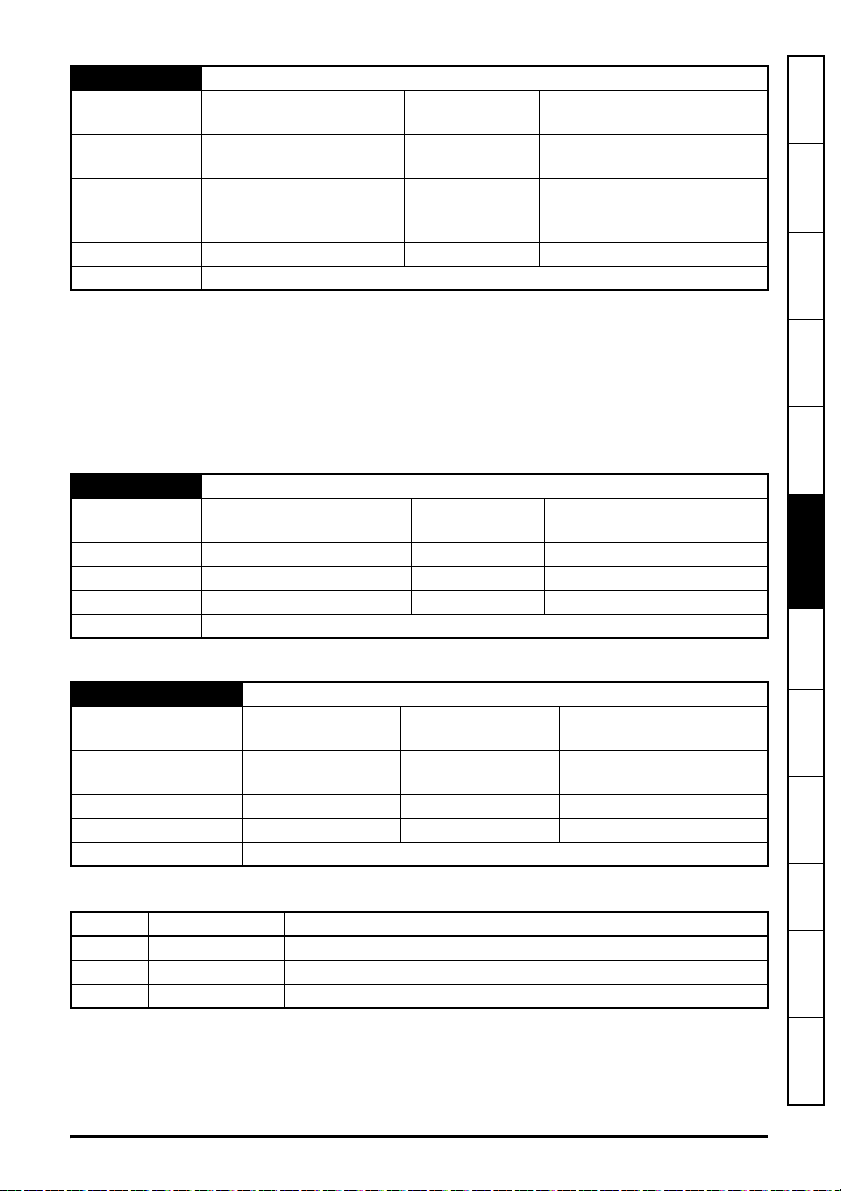
S.02.010 Secondary DNS
Minimum
Default
0
(Display: 0.0.0.0)
0
(Display: 0.0.0.0)
Maximum
Units None
4294967295
(Display:255.255.255.255)
DHCP enabled:
Type 32 Bit User Save Update Rate
write on event;
DHCP disabled: read on reset
Display Format IP Address Decimal Places 0
Coding RW, BU
The module can use this IP address when it wishes to resolve the IP address for a domain name.
This parameter performs the same function as Primary DNS (S.02.009), however the address
specified in this parameter will be tried only when the primary DNS address is unsuccessful.
If DHCP is enabled this parameter becomes read-only, and until a secondary DNS address is
allocated to the module will display 0.0.0.0.
If DHCP is disabled the module will initialize, on reset or power cycle, with the secondary DNS
address stored for the parameter.
S.02.011 MAC Address
Minimum
0
(Display:000000000000)
Maximum
281474976710655
(Display:FFFFFFFFFFFF)
Default None Units None
Type 64 bit volatile Update Rate Power-up write
Display Format MAC Address Decimal Places 0
Coding RO, ND, NC, PT, BU
The 48-bit MAC address of the module.
information
Safety
Introduction
Mechanical
installation
installation
Electrical
Getting started
Parameters
and Protocols
Key features
S.02.020 Priority Protocol
Minimum
Default
0
(Display: None)
0
(Display: None)
Maximum
Units None
2
(Display: EtherNet/IP)
Type 8 Bit User Save Update Rate Background read
Display Format None Decimal Places 0
Coding RW, Txt, BU
Selection of the fieldbus protocol to have priority over all other protocols.
Value Text Description
0 None All protocols have equal priority
1 Modbus TCP Modbus TCP has highest priority
2 EtherNet/IP EtherNet/IP has highest priority
Enables selection of one fieldbus protocol to have priority over others. A tick period of 1 ms will be
given to the highest priority fieldbus protocol, 5 ms to all other fieldbus protocols (equal priority).
If no fieldbus protocol has been selected to have priority over others, all protocols will have equal
priority and a tick rate of 5 ms.
SI-Ethernet User Guide 43
Issue: 3
Applications
PC Tools
Security Diagnostics
Glossary of
terms
Index

S.02.021 Web Server Enable
NOTE
NOTE
NOTE
NOTE
Minimum
Default
0
(Display: Off)
1
(Display: On)
Maximum
Units None
1
(Display: On)
Type 1 Bit User Save Update Rate Background read
Display Format None Decimal Places 0
Coding RW, BU
Controls the running of the web server on the module.
The web server functionality is available in firmware version V01.06.00.22 and onwards.
The web pages do not form part of the firmware download and must be downloaded as
a separate action.
S.02.022 Web Server Port
Minimum 0 Maximum 65535
Default 80 Units None
Type 16 Bit User Save Update Rate
Read on module reset and
S.02.021=On
Display Format None Decimal Places 0
Coding RW, BU
The web server port. This value cannot be changed.
The web server functionality is available in firmware version V01.06.00.22 and onwards.
S.02.024 Ethernet MTU
Minimum 158 Maximum 1500
Default 1500 Units Bytes
Type 16 Bit User Save Update Rate Read on module reset
Display Format None Decimal Places 0
Coding RW, BU
Specifies the MTU (Maximum Transmittable Unit) in bytes allowed by the Ethernet interface.
In some applications this value may be reduced to limit the length of the Ethernet
message packet size in order to reduce the transmission time, however, if this value is
reduced too much then this may result in some messages being corrupted.
44 SI-Ethernet User Guide
Issue: 3
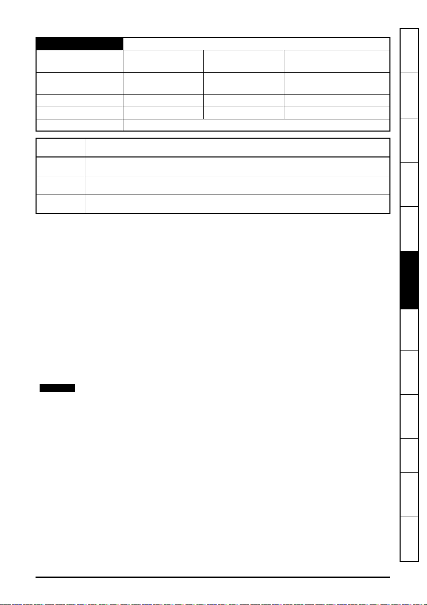
S.02.025 Gateway Mode
NOTE
Minimum
Default 0
0
(Display: Switch)
(Display: Switch)
Maximum
Units
2
(Display: Strict Gateway)
None
Type 8 Bit User Save Update Rate Read on module reset
Display Format None Decimal Places 0
Coding RW, Txt, BU
Value Text
information
Safety
Introduction
Mechanical
installation
0Switch
1 Gateway
2 Strict Gateway
Specifies the operation mode of the gateway. By default the gateway is disabled and the switch
operates in normal switch mode. By enabling the gateway mode all packets are filtered by the
module and prioritized before being forwarded on. In strict mode the gateway will drop packets from
unsupported protocols.
The following protocols are supported in Strict Gateway mode, all other frames will be discarded:
• Ethernet ARP (Address Resolution Protocol) used to resolve the network layer address (IP
address) into a link layer address (MAC address).
• IGMP (Internet Group Management Protocol) used for establishing multicast group
memberships.
• ICMP (Internet Control Message Protocol) used to send error messages such as device not
available or service unavailable error messages.
• eCMP (Control Techniques' proprietary communication protocol).
• CT DIP (Control Techniques' proprietary discovery protocol.
• Modbus TCP/IP.
• BOOTP (Bootstrap Protocol) used to assign IP addresses from a configuration server.
VLAN must be enabled (S.02.030 = On) if either gateway is selected.
installation
Electrical
Getting started
Parameters
and Protocols
Key features
Applications
PC Tools
Security Diagnostics
SI-Ethernet User Guide 45
Issue: 3
Glossary of
terms
Index

S.02.030 VLAN Enable
NOTE
Minimum
Default 0
Type 1 Bit User Save Update Rate Read on module reset
Display Format None Decimal Places 0
Coding RW
Controls whether the module will use VLAN tagging.
When used in conjunction with Drive VLAN ID (S.02.031) network traffic from the interface will be
tagged with the chosen VLAN identifier.
When default value for Drive VLAN ID (S.02.031) is set, enabling this parameter will add VLAN
prioritisation to all packets, helping to ensure real-time packets are not delayed by those of lower
priority. If disabled, prioritization will use the Diffserv field in IP traffic only, meaning non-IP traffic
can still affect real-time IP traffic.
VLAN must be enabled if synchronous cyclic links are used.
S.02.031 Drive VLAN ID
Minimum 0 Maximum 255
Default 0 Units None
Type 8 Bit User Save Update Rate
Display Format None Decimal Places 0
Coding RW, BU
Specifies the VLAN ID that the interface will be a member of. Any packets entering the switch
without this VLAN ID will not be handled.
0
(Display: Off)
(Display: Off)
Maximum
Units
1
(Display: On)
Read on module reset and
S.02.030 = On
S.02.034 Drive Mode
Minimum
Default
Type 8 Bit User Save Update Rate Read on module reset
Display Format None Decimal Places 0
Coding RW, BU, Txt
This parameter provides support for parameter decimal place compatibility with Unidrive SP when
communicating over Modbus TCP/IP or EtherNet/IP.
The following table details the parameter operation.
Value Display Description
0 Unidrive M Values read or written are scaled correctly for the Unidrive M
1 Unidrive SP Values read or written are scaled correctly for the Unidrive SP
Setting this parameter to 1 (On) allows a Unidrive M600/M700/M702 to be used in place of a
Unidrive SP when communicating over Modbus TCP/IP or EtherNet/IP without the need to change
0
(Display: Unidrive M)
0
(Display: Unidrive M)
Maximum
Units None
1
(Display: Unidrive SP)
46 SI-Ethernet User Guide
Issue: 3
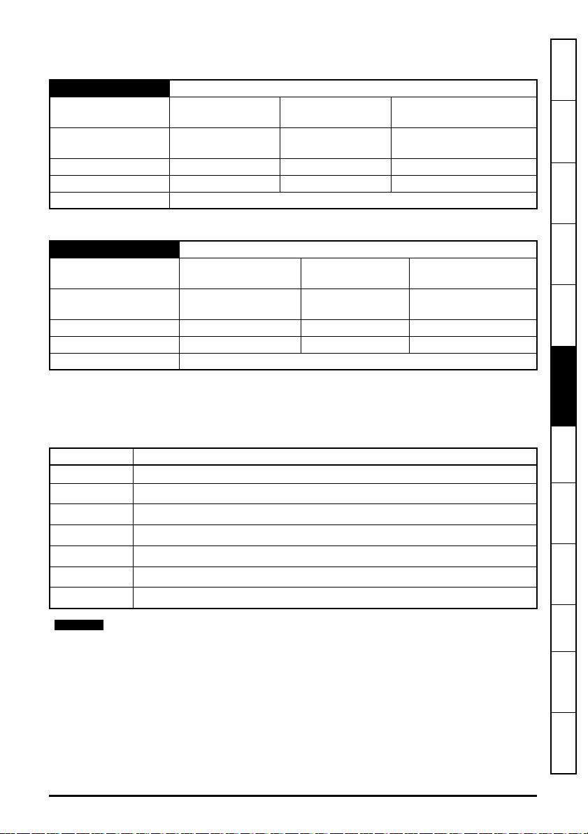
the parameter scaling within the PLC or controller due to differences in the number of decimal
NOTE
places of parameters between the Unidrive SP and Unidrive M range of drives.
S.02.035 Non cyclic enable
Minimum
Default
0
(Display: Off)
0
(Display: Off)
Maximum
Units None
1
(Display: On)
Type 1 Bit User Save Update Rate Background
Display Format None Decimal Places 0
Coding RW
Enable the Non cyclic data transfer.
S.02.036 Non cyclic base parameter
Minimum
Default
0
(Display: 0.00.000)
0
(Display: 0.00.000)
Maximum
Units
59999
(Display: 0.59.999)
Type 16 Bit User Save Update Rate Background
Display Format Slot Menu Param Decimal Places 0
Coding RW, BU
The value in this parameter points to the base address of a group of seven sequential parameters
which are used for handling non cyclic data by user programs.
The following table illustrates the function of each of these parameters with the base parameter
(MM.PPP) identified as S.MM.PPP.
information
Safety
Introduction
Mechanical
installation
installation
Electrical
Getting started
Parameters
and Protocols
Key features
Parameter Description
S.MM.PPP Base parameter - status (bits b15 to b8) and command (bits b7 to b0) information
S.MM.PPP + 1
S.MM.PPP + 2
S.MM.PPP + 3
S.MM.PPP + 4
S.MM.PPP + 5
S.MM.PPP + 6
nd
2
parameter in sequence - Destination IP address (wwwxxx)
rd
3
parameter in sequence - Destination IP address (yyyzzz)
th
4
parameter in sequence - target I source parameter address (SMM)
th
5
parameter in sequence - target I source parameter address (PPP)
th
parameter in sequence - target I source parameter value (LSW) or error code
6
th
7
parameter in sequence - target I source parameter value (MSW)
Each parameter must be at least 16 bits in size.
SI-Ethernet User Guide 47
Issue: 3
Applications
PC Tools
Security Diagnostics
Glossary of
terms
Index

S.MM.PPP : Status and Command
NOTE
This parameter contains the command code (bits b7 to b0) and status (bits b15 to b8) information.
Possible values for Status
are
:
Value Meaning Description
0IDLE Idle.
1 READY The parameter channel is ready to take command.
2 PROCESSING Processing the command.
3 OK The command processed successfully.
4 ERROR Error is detected, detail will be found in the first parameter.
Possible values for Command (bits b7 to
Value Meaning Description
0No
1Check I
2 Read Read one parameter.
3 Write Write one parameter.
Comma
Abort
nd
No command or Abort during a command process.
Check if the status idle or abort from read or write command.
S.MM.PPP + 1 : Destination IP address
b0)
are
:
(wwwxxx)
This parameter is used to specify the first two octets (wwwxxx) of the destination IP address.
S.MM.PPP + 2 : Destination IP address (yyyzzz)
This parameter is used to specify the last two octets (yyyzzz) of the destination IP
The value
127.0.
0.1
would access the current
drive
.
address
S.MM.PPP + 3 : Target / source parameter address (SMM)
This parameter specifies the slot number (S) and menu number (MM) of the target or
source parameter.
S.MM.PPP + 4 : Target / source parameter address (PPP)
This parameter specifies the parameter number
(PPP)
of the target or source parameter
.
S.MM.PPP + 5 : Parameter value (LSW) or error code
This parameter
:
• Stores the least significant word of the value to be written to the destination parameter if the
command is Write (2) or
• Stores the least significant word of the value read from the destination parameter if the
command is read and the status is Done or
• The error code for the process if the status is Error
.
48 SI-Ethernet User Guide
Issue: 3

The following table list the possible error
codes:
Value Meaning Description
-1 Address Type The addressing type is not supported.
-2Timeout A timeout occurred trying to access the specified item.
-3 Access Denied The requesting device does not have sufficient access rights.
-4 Does not exist The specified item does not exist.
Data Type The data could not be converted from the specified type.
-5
-6 Failed Read The value could not be read, reason unknown.
-7 Failed Write The value could not be written, reason unknown.
-8 Not Readable The data could not be read as the source does not allow read access.
-9Not Writeable The data could not be written as the destination does not allow write access.
-10 Over Range The specified value is outside the suitable range for the item.
-11 Request
-12Response Too Big The response will not fit in the maximum response size.
-13 Decimal Place
-14 Invalid Param Invalid parameter in the parameter channel.
-15 Invalid CMD Invalid command.
-16 Invalid
-17 Unknown Error An unknown error happens.
-18
to
-128
Invalid
IP
Reserved Reserved for future use.
The request contained invalid information.
The decimal place information is invalid (i.e. out of range of allowed values for
a write).
Invalid IP address.
information
Safety
Introduction
Mechanical
installation
installation
Electrical
Getting started
Parameters
and Protocols
Key features
S.MM.PPP + 6 : Parameter value (MSW
)
This parameter:
• Stores the most significant word of the value to be written to the destination parameter if the
command is Write (3) or
• Stores the most significant word of the value read from the destination parameter if the
command is Read (2) and the status is OK (3)
6.1.3 Menu 9 – Resources
S.09.001 Cyclic Tx Links Free
Minimum 0 Maximum 255
Default None Units None
Type 8 Bit Volatile Update Rate Background write
Display Format None Decimal Places 0
Coding RO, ND, NC, PT, BU
The number of available transmit cyclic links.
SI-Ethernet User Guide 49
Issue: 3
Applications
PC Tools
Security Diagnostics
Glossary of
terms
Index

S.09.002 Cyclic Rx Links Free
Minimum 0 Maximum 255
Default None Units None
Type 8 Bit Volatile Update Rate Background write
Display Format None Decimal Places 0
Coding RO, ND, NC, PT, BU
The number of available receive cyclic links.
S.09.003 Fieldbus Links Free
Minimum 0 Maximum 255
Default None Units None
Type 8 Bit Volatile Update Rate Background write
Display Format None Decimal Places 0
Coding RO, ND, NC, PT, BU
The number of available transmit / receive process images for fieldbus protocols such as Ethernet/
IP.
S.09.004 Cyclic Mappings Free
Minimum 0 Maximum 255
Default None Units None
Type 8 Bit Volatile Update Rate Background write
Display Format None Decimal Places 0
Coding RO, ND, NC, PT, BU
The number of available mappings in the system for use in cyclic links.
S.09.008 Background cycles per second
Minimum 0 Maximum 65535
Default None Units None
Type 16 Bit Volatile Update Rate Background write
Display Format None Decimal Places 0
Coding RO, ND, NC, BU, PT
The background task cycles per second represents the number of times per second the
background task is currently executing. The background task is responsible for cyclic data
exchange with the drive. With more cyclic data mapped the cycle rate of the task will decrease.
S.09.010 Sync Task % Free
Minimum 0 Maximum 255
Default None Units %
Type 8 Bit Volatile Update Rate Background write
Display Format None Decimal Places 0
Coding RO, ND, NC, PT, BU
Current resource available for the synchronous task.
50 SI-Ethernet User Guide
Issue: 3

S.09.020 Sync Task Worst % Free
NOTE
Minimum 0 Maximum 255
Default None Units %
Type 8 Bit Volatile Update Rate Background write
Display Format None Decimal Places 0
Coding RO, ND, NC, PT, BU
Worst case free resource of the synchronous task.
S.09.030 PCB Temperature
Minimum -128 Maximum 127
Default None Units
o
C
Type 8 Bit Volatile Update Rate Background write
Display Format None Decimal Places 0
Coding RO, ND, NC, PT
6.1.4 Menu 10 – Easy Mode Cyclic Data
The parameters specified here allow up to 3 transmit and 3 receive cyclic links to be configured.
Each receive link can have its own timeout configured with an additional custom action.
For greater control advanced cyclic links can be configured using the cyclic link editor within
Machine Control Studio.
The number of cyclic links is limited to a maximum of 2 when accessing the option
module internal parameters (e.g. the PLC register menus 7x).
Base link parameters
Link Profile Link No.
Tx1 S.10.010 S.10.011 S.10.012 S.10.013 S.10.14 S.10.015* S.10.016
Tx2 S.10.020 S.10.021 S.10.022 S.10.023 S.10.24 S.10.025* S.10.026
Tx3 S.10.030 S.10.031 S.10.032 S.10.033 S.10.34 S.10.035* S.10.036
Src/Dest
Par
Par Count Type IP Address Rate
information
Safety
Introduction
Mechanical
installation
installation
Electrical
Getting started
Parameters
and Protocols
Key features
Applications
PC Tools
Rx1 S.10.040 S.10.041 S.10.042 S.10.043 S.10.044 n/a n/a
Rx2 S.10.050 S.10.051 S.10.052 S.10.053 S.10.054 n/a n/a
Rx3 S.10.060 S.10.061 S.10.062 S.10.063 S.10.064 n/a n/a
* Required if Type set to “unicast”
SI-Ethernet User Guide 51
Issue: 3
Security Diagnostics
Glossary of
terms
Index

S.10.001 Easy Mode Enable
Minimum 0
(Display: Off)
Default
Type 1 Bit User Save Update Rate Background read
Display Format None Decimal Places 0
Coding RW, BU
This parameter is used to enable or disable the Easy Mode protocol interface.
S.10.002 Easy Mode Reset
Minimum 0
Default
Type 1 Bit Volatile Update Rate Background read
Display Format None Decimal Places 0
Coding RW, NC
This parameter is used to perform a warm reset of the Easy Mode protocol interface. When set and
the protocol has reset, the parameter will be reset to zero (Off).
S.10.003 Easy Mode Default
Minimum 0
Default
Type 1 Bit Volatile Update Rate Read on reset
Display Format None Decimal Places 0
Coding RW, NC
This parameter allows the protocol to be defaulted to factory settings. This includes all of the
protocol features, configuration, mappings and stored objects.
1
(Display: On)
(Display: Off)
0
(Display: Off)
(Display: Off)
0
(Display: Off)
Maximum 1
(Display: On)
Units None
Maximum 1
(Display: On)
Units None
Maximum 1
(Display: On)
Units None
S.10.004 Cyclic Messages Per Second
Minimum 0 Maximum 65535
Default None Units Messages/s
Type 16 Bit Volatile Update Rate Background
Display Format None Decimal Places 0
Coding RW, BU, PT, NC, ND
This parameter displays the total number of cyclic (Rx and Tx) messages per second.
52 SI-Ethernet User Guide
Issue: 3
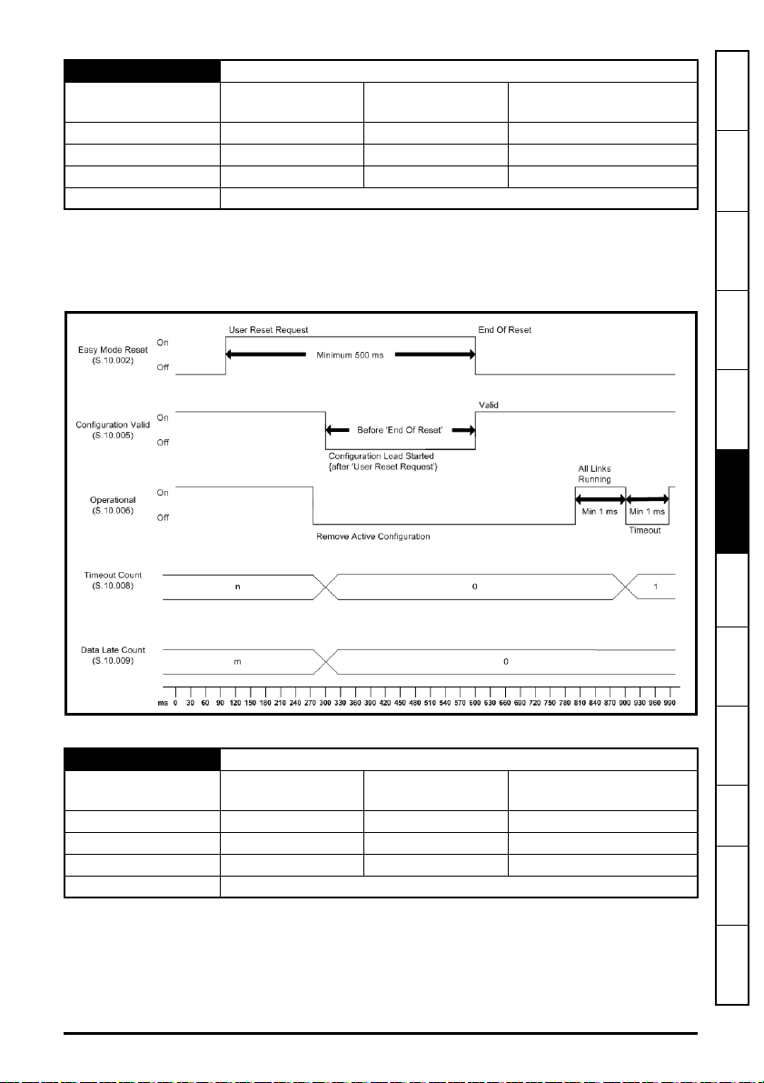
S.10.005 Configuration Valid
Minimum
0
(Display: Off)
Maximum
1
(Display: On)
Default None Units None
Type 1 Bit Volatile Update Rate Read on reset
Display Format None Decimal Places 0
Coding RO, PT, NC, ND
If the active configuration identified by Active Configuration (S.10.007) has no configuration errors
then the configuration is valid and this parameter will be set to 1 (On).
If the active configuration is Easy Mode, made effective through an Easy Mode Reset (S.10.002);
the Configuration Valid (S.10.005) value can be read once Easy Mode Reset (S.10.002) returns to
Off as shown in the associated timing diagram.
information
Safety
Introduction
Mechanical
installation
installation
Electrical
Getting started
Parameters
and Protocols
Key features
If the active configuration is Offline, this represents a configuration via PC tools software.
S.10.006 Operational
Minimum
0
(Display: Off)
Maximum
1
(Display: On)
Default None Units None
Type 1 Bit Volatile Update Rate 1 ms
Display Format None Decimal Places 0
Coding RO, PT, NC, ND
This parameter provides an indication that all links in the active configuration are:
1. Receiving new messages successfully AND
2. Transmitting links; this however does not mean the destination devices are receiving the
messages; this will be dependent on their own state.
SI-Ethernet User Guide 53
Issue: 3
Applications
PC Tools
Security Diagnostics
Glossary of
terms
Index

A receive link timeout will cause this parameter to become cleared (Off) until a new message is
received.
A single data late event will cause this parameter to be Off until the next cyclic message is received
on time.
If low latency reactions to timeout and data late events are required then appropriate actions should
be configured for the relevant links, see Rx1 Timeout Action (S.10.046), Rx2 Timeout Action
(S.10.056) or Rx3 Timeout Action (S.10.066) for further details.
S.10.007 Active Configuration
Minimum
Default None Units None
Type 8 Bit Volatile Update Rate Read on reset
Display Format None Decimal Places 0
Coding RO, PT, NC, ND, Txt, BU
Displays the active configuration source of cyclic data according to the following table.
RTMoE Active configuration values
Value Text Description
0 None No configuration is active
1 Easy Mode Easy Mode configuration is active
2 Offline Offline configuration from PC Tools software is active
S.10.008 Timeout Count
Minimum 0 Maximum 65535
Default None Units None
Type 16 Bit Volatile Update Rate 1 ms
Display Format None Decimal Places 0
Coding RO, PT, NC, ND, BU
This parameter displays the total number of receive timeout events; each timeout event will
increment the count by 1. The parameter value will wrap over to zero.
A receive timeout event occurs when no cyclic data packet is received within the time period
specified in the relevant link number parameter Rx1 Timeout Action (S.10.046), Rx2 Timeout
Action (S.10.056) or Rx3 Timeout Action (S.10.066).
A reset of the configuration will clear this count.
The count can be sampled by a user application in order to detect change since the last sample;
this enables custom reaction to a timeout event occurring on any cyclic receive link which has a
timeout value configured, irrespective of the timeout action for the link.
If a custom timeout reaction is required on a per-link basis then the link action must be chosen
appropriately in Rx1 Timeout Action (S.10.046), Rx2 Timeout Action (S.10.056) or Rx3 Timeout
Action (S.10.066); this could be Clear Output to write zero to all of the cyclic parameters and
implement monitoring code for this condition in the user application.
0
(Display: None)
Maximum
1
(Display: Offline)
54 SI-Ethernet User Guide
Issue: 3

S.10.009 Data Late Count
Minimum 0 Maximum 65535
Default None Units None
Type 16 Bit Volatile Update Rate 1 ms
Display Format None Decimal Places 0
Coding RO, PT, NC, ND, BU
This parameter displays the total number of receive data late events; each data late event will
increment the count by 1. The parameter value will wrap over to zero.
A data late event occurs when a cyclic data packet is received after the 'process at' time specified in
the packet.
A reset of the configuration will clear this count.
The count can be sampled by a user application in order to detect change since the last sample;
this enables custom reaction to a data late event occurring on a synchronous cyclic receive link
which has a received a message containing a time that is now in the past irrespective the defined
action for the link.
S.10.010 Tx1 Link Profile
Minimum 0
Default
(Display: Std)
0
(Display: Std)
Maximum 1
(Display: Sync)
Units None
Type 8 Bit User Save Update Rate Read on reset
Display Format None Decimal Places 0
Coding RW, Txt
information
Safety
Introduction
Mechanical
installation
installation
Electrical
Getting started
Parameters
and Protocols
Key features
Value Text Description
0
1
Std Standard link
Sync Synchronized link
Used to select Tx1 as a standard or synchronous cyclic link.
S.10.011 Tx1 Link Number
Minimum 0 Maximum 255
Default 0 Units None
Type 8 Bit User Save Update Rate Read on reset
Display Format None Decimal Places 0
Coding RW, BU
This parameter is used to set the link number (1 to 255) for the Tx1 link.
SI-Ethernet User Guide 55
Issue: 3
Applications
PC Tools
Security Diagnostics
Glossary of
terms
Index

S.10.012 Tx1 Source Parameter
Minimum
Default
Type 32 Bit User Save Update Rate Read on reset
Display Format Slot Menu Param Decimal Places 0
Coding RW, PT, BU
This parameter sets the source parameter for the Tx1 link.
S.10.013 Tx1 Parameter Count
Minimum 0 Maximum 10
Default 0 Units None
Type 8 Bit User Save Update Rate Read on reset
Display Format None Decimal Places 0
Coding RW, BU
This parameter is used to set the number of contiguous parameters for the Tx1 link.
0
(Display:0.00.000)
0
(Display:0.00.000)
Maximum
Units None
499999
(Display: 4.99.999)
56 SI-Ethernet User Guide
Issue: 3

S.10.014 Tx1 Transmission Type
NOTE
Minimum
Default
0
(Display: Unicast
0
(Display: Unicast
Maximum
)
Units None
)
11
(Display: Multicast10)
Type 8 Bit User Save Update Rate Read on reset
Display Format None Decimal Places 0
Coding RW, Txt, BU
information
Safety
Introduction
Mechanical
installation
Value Text Description
0 Unicast Link is unicast to the IP address specified
1 Broadcast Link is broadcast (255.255.255.255)
2 Multicast1 Link is multicast to the IP address (239.255.0.1)
3 Multicast2 Link is multicast to the IP address (239.255.0.2)
4 Multicast3 Link is multicast to the IP address (239.255.0.3)
5 Multicast4 Link is multicast to the IP address (239.255.0.4)
6 Multicast5 Link is multicast to the IP address (239.255.0.5)
7 Multicast6 Link is multicast to the IP address (239.255.0.6)
8 Multicast7 Link is multicast to the IP address (239.255.0.7)
9 Multicast8 Link is multicast to the IP address (239.255.0.8)
10 Multicast9 Link is multicast to the IP address (239.255.0.9)
11 Multicast10 Link is multicast to the IP address (239.255.0.10)
This parameter specifies the type of transmission for the Tx1 link.
S.10.015 Tx1 Destination Address
Minimum
Default
0
(Display:0.0.0.0)
0
(Display:0.0.0.0)
Maximum
Units None
4294967295
(Display: 255.255.255.255)
Type 32 Bit User Save Update Rate Read on reset
Display Format IP Address Decimal Places 0
Coding RW, BU
installation
Electrical
Getting started
Parameters
and Protocols
Key features
Applications
PC Tools
Security Diagnostics
This parameter specifies the IP address of the destination device for the Tx1 link. If Tx1 Link
Transmission Type (S.10.014) is set to either broadcast or one of the multicast settings this
parameter will display the appropriate address.
This parameter value is not locked and may be changed by the user, if this value is
changed to any of the multicast addresses (Multicast1, Multicast2, Multicast3 or
Multicast4) or the broadcast address then Tx1 Link Transmission Type (S.10.014) will
indicate the appropriate setting.
SI-Ethernet User Guide 57
Issue: 3
Glossary of
terms
Index

S.10.016 Tx1 Message Rate
Minimum 0 Maximum 100
Default 0 Units ms
Type 8 Bit User Save Update Rate Read on reset
Display Format None Decimal Places 0
Coding RW, BU
Defines, in milliseconds, the rate at which Tx1 Link will be transmitted. A value of zero disables the
transmission of data.
For synchronous links, to support the Advanced Machine Controller, only values of 1, 2, 4, 8, 16 or
32 are valid.
S.10.019 Tx1 Link Status
Minimum -31
(Display: Disabled)
Default None Units None
Type 8 Bit Volatile Update Rate Write on reset
Display Format None Decimal Places 0
Coding RO, Txt, ND, NC, PT
Value Text Description
-31 Disabled Easy Mode protocol is disabled or link number set to 0
-30 VLAN disabled
-29 Reserved 29 Reserved for future use
-28 Reserved 28 Reserved for future use
-27 Reserved 27 Reserved for future use
-26 Reserved 26 Reserved for future use
-25 Reserved 25 Reserved for future use
-24 Reserved 24 Reserved for future use
-23 Reserved 23 Reserved for future use
-22 Invalid DST IP Destination IP address is invalid
-21 SYNC unsupported
-20 MEC offset Incorrect MEC offset
-19 Invalid tx rate Tx rate must be a factor of 1 second
-18 Too many mapping
-17 Link busy The link specified is busy
-16 Invalid profile The profile is invalid
-15 Invalid mapping The mapped parameter does not exist
Maximum
VLAN is required in order to guarantee timing in
synchronous mode but it is disabled
Sync link does not support mappings to other option
parameters
The number of mapping items exceeds the range
supported
2
(Display: OK sync)
58 SI-Ethernet User Guide
Issue: 3

Value Text Description
-14 Read only param The mapped parameter is read only
-13 Msg mismatch Link number and direction do not match
-12 Msg too long Resulting message is too long
-11 Attrib NA Attribute not available
-10 Attrib RO Attribute is read only
-9 Attrib missing Attribute is missing
-8 Timeout Timeout
-7 In error The specified link is in error state
-6 Link num in use The link number specified is already in use
-5 Not editable The link specified is not editable
-4 Invalid link num An invalid link number was specified
-3 Invalid args Link number / argument zero or invalid
-2 Too many links Maximum number of links has been reached
-1 Out of memory Failed to allocate memory
0 OK Configuration of link successful
1 Not running Ok, not running
2 OK sync Configuration of synchronous link successful
This reports the links status if it has been loaded. A Easy Mode Reset (S.10.002) is required to load
any changes.
S.10.020 Tx2 Link Profile
Minimum 0
Default
(Display: Std)
0
(Display: Std)
Maximum 1
(Display: Sync)
Units None
Type 8 Bit User Save Update Rate Read on reset
Display Format None Decimal Places 0
Coding RW, Txt
information
Safety
Introduction
Mechanical
installation
installation
Electrical
Getting started
Parameters
and Protocols
Key features
Applications
PC Tools
Security Diagnostics
Value Text Description
0
1
Std Standard link
Sync Synchronized link
Used to select Tx2 as a standard or synchronous cyclic link.
SI-Ethernet User Guide 59
Issue: 3
Glossary of
terms
Index

S.10.021 Tx2 Link Number
Minimum 0 Maximum 255
Default 0 Units None
Type 8 Bit User Save Update Rate Read on reset
Display Format None Decimal Places 0
Coding RW, BU
This parameter is used to set the link number (1 to 255) for the Tx2 link.
S.10.022 Tx2 Source Parameter
Minimum
Default
Type 32 Bit User Save Update Rate Read on reset
Display Format Slot Menu Param Decimal Places 0
Coding RW, PT, BU
This parameter sets the source parameter for the Tx2 link.
S.10.023 Tx2 Parameter Count
Minimum 0 Maximum 10
Default 0 Units None
Type 8 Bit User Save Update Rate Read on reset
Display Format None Decimal Places 0
Coding RW, BU
This parameter is used to set the number of contiguous parameters for the Tx2 link.
0
(Display: 0.00.000)
0
(Display: 0.00.000)
Maximum
Units None
499999
(Display: 4.99.999)
60 SI-Ethernet User Guide
Issue: 3
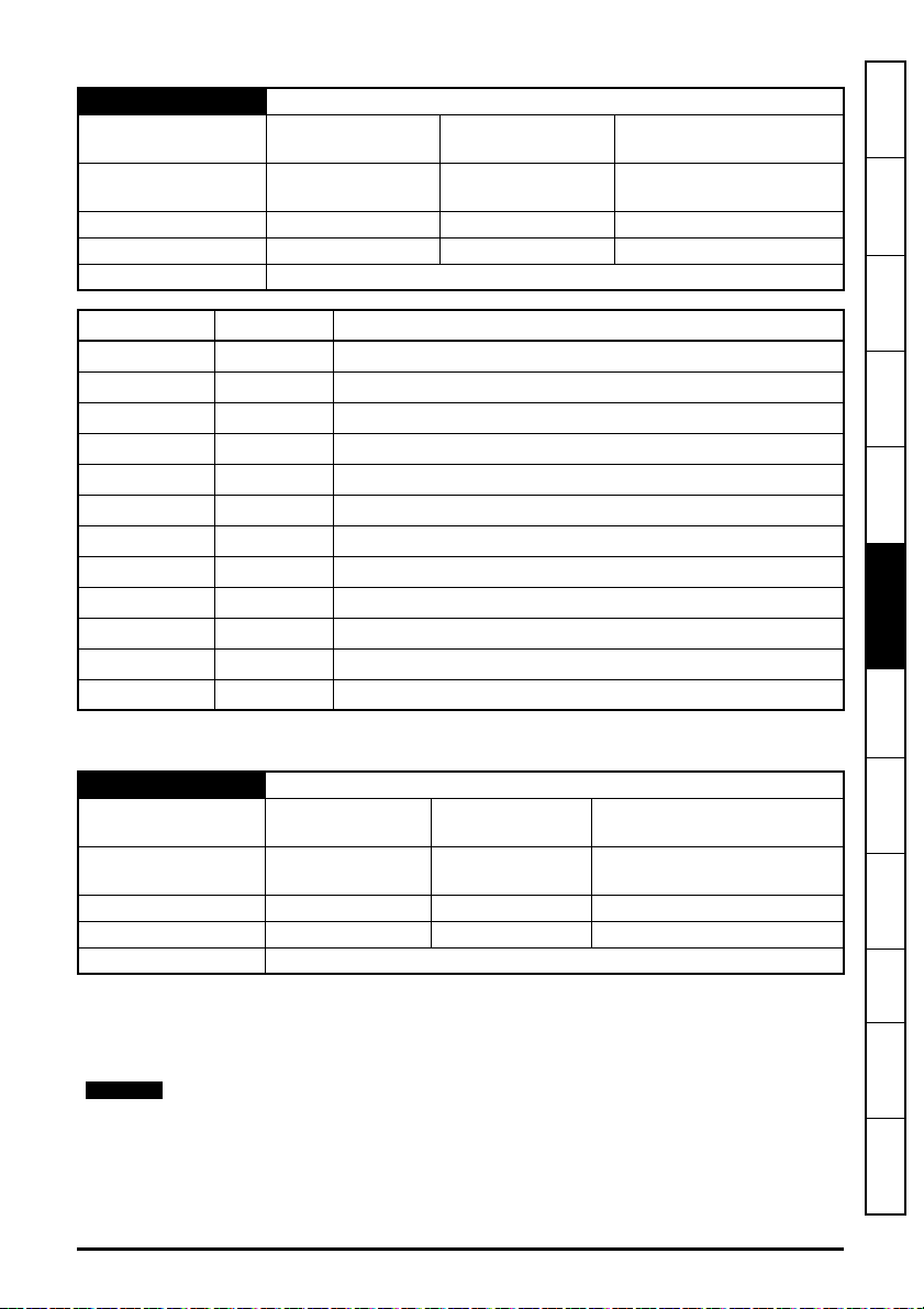
S.10.024 Tx2 Transmission Type
NOTE
Minimum
Default
0
(Display: Unicast)
0
(Display: Unicast)
Maximum
Units None
11
(Display: Multicast10)
Type 8 Bit User Save Update Rate Read on reset
Display Format None Decimal Places 0
Coding RW, Txt, BU
Value Text Description
0 Unicast Link is unicast to the IP address specified
1 Broadcast Link is broadcast (255.255.255.255)
2 Multicast1 Link is multicast to the IP address (239.255.0.1)
3 Multicast2 Link is multicast to the IP address (239.255.0.2)
4 Multicast3 Link is multicast to the IP address (239.255.0.3)
5 Multicast4 Link is multicast to the IP address (239.255.0.4)
6 Multicast5 Link is multicast to the IP address (239.255.0.5)
7 Multicast6 Link is multicast to the IP address (239.255.0.6)
8 Multicast7 Link is multicast to the IP address (239.255.0.7)
9 Multicast8 Link is multicast to the IP address (239.255.0.8)
10 Multicast9 Link is multicast to the IP address (239.255.0.9)
11 Multicast10 Link is multicast to the IP address (239.255.0.10)
information
Safety
Introduction
Mechanical
installation
installation
Electrical
Getting started
Parameters
and Protocols
Key features
This specifies the type of transmission for the Tx2 link.
S.10.025 Tx2 Destination Address
Minimum
Default
0
(Display:0.0.0.0)
0
(Display:0.0.0.0)
Maximum
Units None
4294967295
(Display: 255.255.255.255)
Type 32 Bit User Save Update Rate Read on reset
Display Format IP Address Decimal Places 0
Coding RW, BU
This parameter specifies the IP address of the destination device for the Tx2 link. If Tx2 Link
Transmission Type (S.10.024) is set to either broadcast or one of the multicast settings this
parameter will display the appropriate address.
This parameter value is not locked and may be changed by the user, if this value is
changed to any of the multicast addresses (Multicast1, Multicast2 to Multicast10) or the
broadcast address then Tx2 Link Transmission Type (S.10.024) will indicate the
appropriate setting.
SI-Ethernet User Guide 61
Issue: 3
Applications
PC Tools
Security Diagnostics
Glossary of
terms
Index

S.10.026 Tx2 Message Rate
Minimum 0 Maximum 100
Default 0 Units ms
Type 8 Bit User Save Update Rate Read on reset
Display Format None Decimal Places 0
Coding RW, BU
Defines, in milliseconds, the rate at which Tx2 Link will be transmitted. A value of zero disables the
transmission of data.
For synchronous links, to support the Advanced Machine Controller, only values of 1, 2, 4, 8, 16 or
32 are valid
S.10.029 Tx2 Link Status
Minimum
Default None Units None
Type 8 Bit Volatile Update Rate Write on reset
Display Format None Decimal Places 0
Coding RO, Txt, NC, ND, PT
Value Text Description
-31 Disabled Easy Mode protocol is disabled or link number set to 0
-30 VLAN disabled
-29 Reserved 29 Reserved for future use
-28 Reserved 28 Reserved for future use
-27 Reserved 27 Reserved for future use
-26 Reserved 26 Reserved for future use
-25 Reserved 25 Reserved for future use
-24 Reserved 24 Reserved for future use
-23 Reserved 23 Reserved for future use
-22 Invalid DST IP Destination IP address is invalid
-21 SYNC unsupported
-20 MEC offset Incorrect MEC offset
-19 Invalid tx rate Tx rate must be a factor of 1 second
-18 Too many mapping
-17 Link busy The link specified is busy
-16 Invalid profile The profile is invalid
-15 Invalid mapping The mapped parameter does not exist
-31
(Display: Disabled)
Maximum
VLAN is required in order to guarantee timing in
synchronous mode but it is disabled
Sync link does not support mappings to other option
parameters
The number of mapping items exceeds the range
supported
2
(Display: OK sync)
62 SI-Ethernet User Guide
Issue: 3

Value Text Description
-14 Read only param The mapped parameter is read only
-13 Msg mismatch Link number and direction do not match
-12 Msg too long Resulting message is too long
-11 Attrib NA Attribute not available
-10 Attrib RO Attribute is read only
-9 Attrib missing Attribute is missing
-8 Timeout Timeout
-7 In error The specified link is in error state
-6 Link num in use The link number specified is already in use
-5 Not editable The link specified is not editable
-4 Invalid link num An invalid link number was specified
-3 Invalid args Link number / argument zero or invalid
-2 Too many links Maximum number of links has been reached
-1 Out of memory Failed to allocate memory
0 OK Configuration of link successful
1 Not running Ok, not running
2 OK sync Configuration of synchronous link successful
This parameter reports the link’s status if it has been loaded. A Easy Mode Reset (S.10.002) is
required to load any changes.
S.10.030 Tx3 Link Profile
Minimum
Default
0
(Display: Std)
0
(Display: Std)
Maximum
Units None
1
(Display: Sync)
Type 8 Bit User Save Update Rate Read on reset
Display Format None Decimal Places 0
Coding RW, Txt
information
Safety
Introduction
Mechanical
installation
installation
Electrical
Getting started
Parameters
and Protocols
Key features
Applications
PC Tools
Security Diagnostics
Value Text Description
0
1
Std Standard link
Sync Synchronized link
Used to select Tx3 as a standard or synchronous cyclic link.
SI-Ethernet User Guide 63
Issue: 3
Glossary of
terms
Index

S.10.031 Tx3 Link Number
Minimum 0 Maximum 255
Default 0 Units None
Type 8 Bit User Save Update Rate Read on reset
Display Format None Decimal Places 0
Coding RW, BU
This parameter is used to set the link number (1 to 255) for the Tx3 link.
S.10.032 Tx3 Source Parameter
Minimum
Default
Type 32 Bit User Save Update Rate Read on reset
Display Format Slot Menu Param Decimal Places 0
Coding RW, PT, BU
This parameter sets the source parameter for the Tx3 link.
S.10.033 Tx3 Parameter Count
Minimum 0 Maximum 10
Default 0 Units None
Type 8 Bit User Save Update Rate Read on reset
Display Format None Decimal Places 0
Coding RW, BU
This parameter is used to set the number of contiguous parameters for the Tx3 link.
0
(Display: 0.00.000)
0
(Display: 0.00.000)
Maximum
Units None
499999
(Display: 4.99.999)
64 SI-Ethernet User Guide
Issue: 3

S.10.034 Tx3 Transmission Type
NOTE
Minimum
Default
0
(Display: Unicast)
0
(Display: Unicast)
Maximum
Units None
11
(Display: Multicast10)
Type 8 Bit User Save Update Rate Read on reset
Display Format None Decimal Places 0
Coding RW, Txt, BU
Value Text Description
0 Unicast Link is unicast to the IP address specified
1 Broadcast Link is broadcast (255.255.255.255)
2 Multicast1 Link is multicast to the IP address (239.255.0.1)
3 Multicast2 Link is multicast to the IP address (239.255.0.2)
4 Multicast3 Link is multicast to the IP address (239.255.0.3)
5 Multicast4 Link is multicast to the IP address (239.255.0.4)
6 Multicast5 Link is multicast to the IP address (239.255.0.5)
7 Multicast6 Link is multicast to the IP address (239.255.0.6)
8 Multicast7 Link is multicast to the IP address (239.255.0.7)
9 Multicast8 Link is multicast to the IP address (239.255.0.8)
10 Multicast9 Link is multicast to the IP address (239.255.0.9)
11 Multicast10 Link is multicast to the IP address (239.255.0.10)
information
Safety
Introduction
Mechanical
installation
installation
Electrical
Getting started
Parameters
and Protocols
Key features
This parameter specifies the type of transmission for the Tx3 link.
S.10.035 Tx3 Destination Address
Minimum
Default
0
(Display:0.0.0.0)
0
(Display:0.0.0.0)
Maximum
Units None
4294967295
(Display: 255.255.255.255)
Type 32 Bit User Save Update Rate Read on reset
Display Format IP Address Decimal Places 0
Coding RW, BU
This parameter specifies the IP address of the destination device for the Tx3 link. If Tx3 Link
Transmission Type (S.10.034) is set to either broadcast or one of the multicast settings this
parameter will display the appropriate address.
This parameter value is not locked and may be changed by the user, if this value is
changed to any of the multicast addresses (Multicast1, Multicast2 to Multicast10) or the
broadcast address then Tx3 Link Transmission Type (S.10.034) will indicate the
appropriate setting.
SI-Ethernet User Guide 65
Issue: 3
Applications
PC Tools
Security Diagnostics
Glossary of
terms
Index

S.10.036 Tx3 Message Rate
Minimum 0 Maximum 100
Default 0 Units ms
Type 8 Bit User Save Update Rate Read on reset
Display Format None Decimal Places 0
Coding RW, BU
Defines, in milliseconds, the rate at which Tx3 Link will be transmitted. A value of zero disables the
transmission of data.
For synchronous links, to support the Advanced Machine Controller, only values of 1, 2, 4, 8, 16 or
32 are valid
S.10.039 Tx3 Link Status
Minimum
Default None Units None
Type 8 Bit Volatile Update Rate Write on reset
Display Format None Decimal Places 0
Coding RO, Txt, NC, ND, PT
Value Text Description
-31 Disabled Easy Mode protocol is disabled or link number set to 0
-30 VLAN disabled
-29 Reserved 29 Reserved for future use
-28 Reserved 28 Reserved for future use
-27 Reserved 27 Reserved for future use
-26 Reserved 26 Reserved for future use
-25 Reserved 25 Reserved for future use
-24 Reserved 24 Reserved for future use
-23 Reserved 23 Reserved for future use
-22 Invalid DST IP Destination IP address is invalid
-21 SYNC unsupported
-20 MEC offset Incorrect MEC offset
-19 Invalid tx rate Tx rate must be a factor of 1 second
-18 Too many mapping
-17 Link busy The link specified is busy
-16 Invalid profile The profile is invalid
-31
(Display: Disabled)
Maximum
VLAN is required in order to guarantee timing in
synchronous mode but it is disabled
Sync link does not support mappings to other option
parameters
The number of mapping items exceeds the range
supported
2
(Display: OK sync)
66 SI-Ethernet User Guide
Issue: 3

Value Text Description
-15 Invalid mapping The mapped parameter does not exist
-14 Read only param The mapped parameter is read only
-13 Msg mismatch Link number and direction do not match
-12 Msg too long Resulting message is too long
-11 Attrib NA Attribute not available
-10 Attrib RO Attribute is read only
-9 Attrib missing Attribute is missing
-8 Timeout Timeout
-7 In error The specified link is in error state
-6 Link num in use The link number specified is already in use
-5 Not editable The link specified is not editable
-4 Invalid link num An invalid link number was specified
-3 Invalid args Link number / argument zero or invalid
-2 Too many links Maximum number of links has been reached
-1 Out of memory Failed to allocate memory
0 OK Configuration of link successful
1 Not running Ok, not running
2 OK sync Configuration of synchronous link successful
This parameter reports the link’s status if it has been loaded. A Easy Mode Reset (S.10.002) is
required to load any changes.
information
Safety
Introduction
Mechanical
installation
installation
Electrical
Getting started
Parameters
and Protocols
Key features
S.10.040 Rx1 Link Profile
Minimum 0
Default
(Display: Std)
0
(Display: Std)
Maximum 1
(Display: Sync)
Units None
Type 8 Bit User Save Update Rate Read on reset
Display Format None Decimal Places 0
Coding RW, Txt
Value Text Description
0
1
Std Standard link
Sync Synchronized link
Used to select Rx1 as a standard or synchronous cyclic link.
SI-Ethernet User Guide 67
Issue: 3
Applications
PC Tools
Security Diagnostics
Glossary of
terms
Index

S.10.041 Rx1 Link Number
Minimum 0 Maximum 255
Default 0 Units None
Type 8 Bit User Save Update Rate Read on reset
Display Format None Decimal Places 0
Coding RW, BU
This parameter is used to set the link number (1 to 255) for the Rx1 link.
S.10.042 Rx1 Destination Parameter
Minimum
Default
Type 32 Bit User Save Update Rate Read on reset
Display Format Slot Menu Param Decimal Places 0
Coding RW, BU
This parameter sets the destination parameter for the Rx1 link.
S.10.043 Rx1 Parameter Count
Minimum 0 Maximum 10
Default 0 Units None
Type 8 Bit User Save Update Rate Read on reset
Display Format None Decimal Places 0
Coding RW, BU
This parameter is used to set the number of contiguous parameters for the Rx1 link.
0
(Display: 0.00.000)
0
(Display: 0.00.000)
Maximum
Units None
499999
(Display: 4.99.999)
68 SI-Ethernet User Guide
Issue: 3

S.10.044 Rx1 Source Type
NOTE
Minimum
Default
0
(Display: Unicast)
0
(Display: Unicast)
Maximum
Units None
11
(Display: Multicast10)
Type 8 Bit User Save Update Rate Read on reset
Display Format None Decimal Places 0
Coding RW, Txt, BU
Value Text Description
0 Unicast Link is unicast to the IP address specified
1 Broadcast Link is broadcast (255.255.255.255)
2 Multicast1 Link is multicast to the IP address (239.255.0.1)
3 Multicast2 Link is multicast to the IP address (239.255.0.2)
4 Multicast3 Link is multicast to the IP address (239.255.0.3)
5 Multicast4 Link is multicast to the IP address (239.255.0.4)
6 Multicast5 Link is multicast to the IP address (239.255.0.5)
7 Multicast6 Link is multicast to the IP address (239.255.0.6)
8 Multicast7 Link is multicast to the IP address (239.255.0.7)
9 Multicast8 Link is multicast to the IP address (239.255.0.8)
10 Multicast9 Link is multicast to the IP address (239.255.0.9)
11 Multicast10 Link is multicast to the IP address (239.255.0.10)
information
Safety
Introduction
Mechanical
installation
installation
Electrical
Getting started
Parameters
and Protocols
Key features
This specifies the type of transmission for the Rx1 link.
S.10.045 Rx1 Timeout
Minimum 0 Maximum 65535
Default 100 Units ms
Type 16 Bit User Save Update Rate Read on reset
Display Format None Decimal Places 0
Coding RW, BU
This parameter specifies the watchdog timer for the Rx1 link. If no cyclic data is received on the
Rx1 link the action taken will be determined by the setting in Rx1 Timeout Action (S.10.046).
It is good system design to allow for some message loss by setting the timeout duration
to be greater than the transmit period by a factor of 2 or more.
SI-Ethernet User Guide 69
Issue: 3
Applications
PC Tools
Security Diagnostics
Glossary of
terms
Index

S.10.046 Rx1 Timeout Action
NOTE
Minimum
Default
Type 8 Bit User Save Update Rate Read on reset
Display Format None Decimal Places 0
Coding RW, Txt, BU
Value Text Description
0 Trip Trip drive with Slx.Er and sub-trip code 106 (Cyclic Timeout)
1 Clear output PLC output parameters will have their values set to zero
2 Hold last Hold the last value in output parameters
Defines the action to be taken for a timeout on the Rx1 link.
S.10.047 Rx1 Timeout Event Dest
Minimum
Default
Type 8 Bit User save Update Rate Read on reset
Display Format None Decimal Places 0
Coding RW, Txt, BU
0
(Display: Trip)
0
(Display: Trip)
0
(Display: This slot)
0
(Display: This slot)
Maximum
Units None
Maximum
Units None
2
(Display: Hold last)
4
(Display: Slot 4)
Value Text Description
0 This slot Trigger module event in this slot
1 Slot 1 Trigger module event in slot 1
2 Slot 2 Trigger module event in slot 2
3 Slot 3 Trigger module event in slot 3
4 Slot 4 Trigger module event in slot 4
This parameter defines the slot in which an event will occur if a cyclic data timeout occurs on the
Rx1 link.
This feature is not yet implemented.
70 SI-Ethernet User Guide
Issue: 3

S.10.048 Rx1 Timeout Event Type
NOTE
Minimum
Default
0
(Display: No Event)
0
(Display: No Event)
Maximum
Units None
4
(Display: Event3)
Type 8 Bit User save Update Rate Read on reset
Display Format None Decimal Places 0
Coding RW, Txt, BU
Value Text Description
0 No Event No event
1 Event Trigger module event
2 Event 1 Trigger module event 1
3 Event 2 Trigger module event 2
4 Event 3 Trigger module event 3
Defines the event to trigger in the given destination, as specified in Rx1 Timeout Event Destination
(S.10.047), if a cyclic data timeout occurs on the Rx1 link.
This feature is not yet implemented.
S.10.049 Rx1 Link Status
Minimum
-31
(Display: Disabled)
Maximum
2
(Display: OK sync)
Default None Units None
Type 8 Bit Volatile Update Rate Write on reset
Display Format None Decimal Places 0
Coding RO, Txt, NC, ND, PT
information
Safety
Introduction
Mechanical
installation
installation
Electrical
Getting started
Parameters
and Protocols
Key features
Applications
PC Tools
Value Text Description
-31 Disabled Easy Mode protocol is disabled or link number set to 0
-30 VLAN disabled
VLAN is required in order to guarantee timing in
synchronous mode but it is disabled
-29 Reserved 29 Reserved for future use
-28 Reserved 28 Reserved for future use
-27 Reserved 27 Reserved for future use
-26 Reserved 26 Reserved for future use
-25 Reserved 25 Reserved for future use
-24 Reserved 24 Reserved for future use
-23 Reserved 23 Reserved for future use
SI-Ethernet User Guide 71
Issue: 3
Security Diagnostics
Glossary of
terms
Index

Value Text Description
-22 Invalid DST IP Destination IP address is invalid
-21 SYNC unsupported
-20 MEC offset Incorrect MEC offset
-19 Invalid tx rate Tx rate must be a factor of 1 second
-18 Too many mapping
-17 Link busy The link specified is busy
-16 Invalid profile The profile is invalid
-15 Invalid mapping The mapped parameter does not exist
-14 Read only param The mapped parameter is read only
-13 Msg mismatch Link number and direction do not match
-12 Msg too long Resulting message is too long
-11 Attrib NA Attribute not available
-10 Attrib RO Attribute is read only
-9 Attrib missing Attribute is missing
-8 Timeout Timeout
-7 In error The specified link is in error state
-6 Link num in use The link number specified is already in use
-5 Not editable The link specified is not editable
-4 Invalid link num An invalid link number was specified
-3 Invalid args Link number / argument zero or invalid
-2 Too many links Maximum number of links has been reached
-1 Out of memory Failed to allocate memory
0 OK Configuration of link successful
1 Not running Ok, not running
2 OK sync Configuration of synchronous link successful
This parameter reports the link’s status if it has been loaded. A Easy Mode Reset (S.10.002) is
required to load any changes.
Sync link does not support mappings to other option
parameters
The number of mapping items exceeds the range
supported
72 SI-Ethernet User Guide
Issue: 3

S.10.050 Rx2 Link Profile
Minimum
Default
0
(Display: Std)
0
(Display: Std)
Maximum
Units None
1
(Display: Sync)
Type 8 Bit User Save Update Rate Read on reset
Display Format None Decimal Places 0
Coding RW, Txt
Value Text Description
0
1
Std Standard link
Sync Synchronized link
Used to select Rx2 as a standard or synchronous cyclic link.
S.10.051 Rx2 Link Number
Minimum 0 Maximum 255
Default 0 Units None
Type 8 Bit User Save Update Rate Read on reset
Display Format None Decimal Places 0
Coding RW, BU
This parameter is used to set the link number (1 to 255) for the Rx2 link.
S.10.052 Rx2 Destination Parameter
Minimum
Default
0
(Display: 0.00.000)
0
(Display: 0.00.000)
Maximum
Units None
499999
(Display: 4.99.999)
Type 32 Bit User Save Update Rate Read on reset
Display Format Slot Menu Param Decimal Places 0
Coding RW, PT, BU
This parameter sets the destination parameter for the Rx2 link.
information
Safety
Introduction
Mechanical
installation
installation
Electrical
Getting started
Parameters
and Protocols
Key features
Applications
PC Tools
Security Diagnostics
S.10.053 Rx2 Parameter Count
Minimum 0 Maximum 10
Default 0 Units None
Type 8 Bit User Save Update Rate Read on reset
Display Format None Decimal Places 0
Coding RW, BU
This is used to set the number of contiguous parameters for the Rx2 link.
SI-Ethernet User Guide 73
Issue: 3
Glossary of
terms
Index

S.10.054 Rx2 Source Type
NOTE
Minimum
Default
Type 8 Bit User Save Update Rate Read on reset
Display Format None Decimal Places 0
Coding RW, Txt, BU
Value Text Description
0 Unicast Link is unicast to the IP address specified
1 Broadcast Link is broadcast (255.255.255.255)
2 Multicast1 Link is multicast to the IP address (239.255.0.1)
3 Multicast2 Link is multicast to the IP address (239.255.0.2)
4 Multicast3 Link is multicast to the IP address (239.255.0.3)
5 Multicast4 Link is multicast to the IP address (239.255.0.4)
6 Multicast5 Link is multicast to the IP address (239.255.0.5)
7 Multicast6 Link is multicast to the IP address (239.255.0.6)
8 Multicast7 Link is multicast to the IP address (239.255.0.7)
9 Multicast8 Link is multicast to the IP address (239.255.0.8)
10 Multicast9 Link is multicast to the IP address (239.255.0.9)
11 Multicast10 Link is multicast to the IP address (239.255.0.10)
0
(Display: Unicast)
0
(Display: Unicast)
Maximum
Units None
11
(Display: Multicast10)
This parameter specifies the type of transmission for the Rx2 link.
S.10.055 Rx2 Timeout
Minimum 0 Maximum 65535
Default 100 Units ms
Type 16 Bit User Save Update Rate Read on reset
Display Format None Decimal Places 0
Coding RW, BU
This parameter specifies the watchdog timer for the Rx2 link. If no cyclic data is received on the
Rx2 link the action taken will be determined by the setting in Rx2 Timeout Action (S.10.056).
It is good system design to allow for some message loss by setting the timeout duration
to be greater than the transmit period by a factor of 2 or more.
74 SI-Ethernet User Guide
Issue: 3
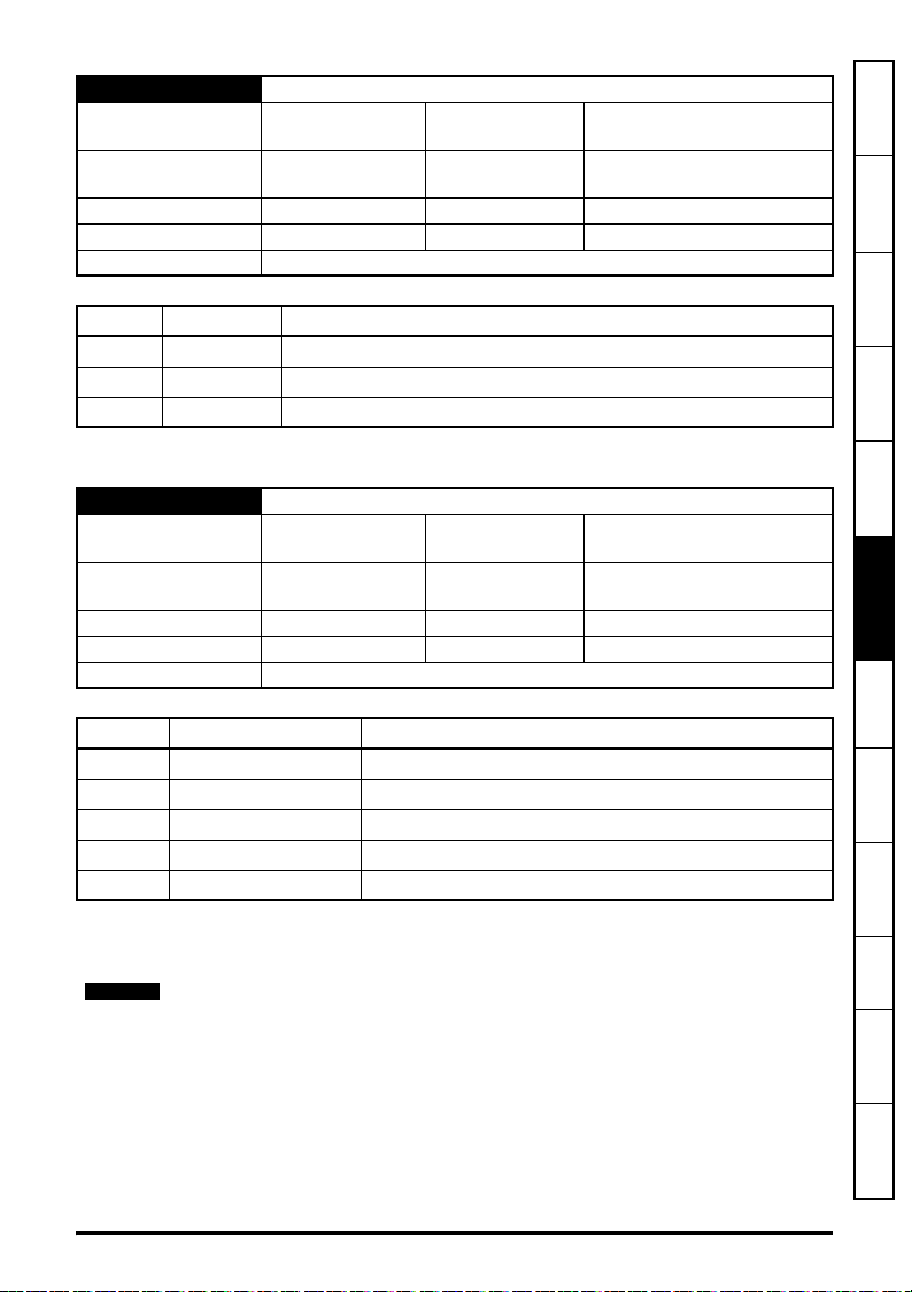
S.10.056 Rx2 Timeout Action
NOTE
Minimum
Default
0
(Display: Trip)
0
(Display: Trip)
Maximum
Units None
2
(Display: Hold last)
Type 8 Bit User save Update Rate Read on reset
Display Format None Decimal Places 0
Coding RW, Txt, BU
Value Text Description
0 Trip Trip drive with Slx.Er and sub-trip code 106 (Cyclic Timeout)
1 Clear output PLC output parameters will have their values set to zero
2 Hold last Hold the last value in output parameters
Defines the action to be taken for a timeout on the Rx2 link.
S.10.057 Rx2 Timeout Event Dest
Minimum
Default
0
(Display: This slot)
0
(Display: This slot)
Maximum
Units None
4
(Display: Slot 4)
Type 8 Bit User save Update Rate Read on reset
Display Format None Decimal Places 0
Coding RW, Txt, BU
information
Safety
Introduction
Mechanical
installation
installation
Electrical
Getting started
Parameters
and Protocols
Key features
Value Text Description
0 This slot Trigger module event in this slot
1 Slot 1 Trigger module event in slot 1
2 Slot 2 Trigger module event in slot 2
3 Slot 3 Trigger module event in slot 3
4 Slot 4 Trigger module event in slot 4
This parameter defines the slot in which an event will occur if a cyclic data timeout occurs on the
Rx2 link.
This feature is not yet implemented.
SI-Ethernet User Guide 75
Issue: 3
Applications
PC Tools
Security Diagnostics
Glossary of
terms
Index

S.10.058 Rx2 Timeout Event Type
NOTE
Minimum
Default
Type 8 Bit User save Update Rate Read on reset
Display Format None Decimal Places 0
Coding RW, Txt, BU
Value Text Description
0 No Event No event
1 Event Trigger module event
2 Event 1 Trigger module event 1
3 Event 2 Trigger module event 2
4 Event 3 Trigger module event 3
Defines the event to trigger in the given destination, as specified in Rx2 Timeout Event Destination
(S.10.057), if a cyclic data timeout occurs on the Rx2 link.
This feature is not yet implemented.
S.10.059 Rx2 Link Status
Minimum
Default None Units None
Type 8 Bit Volatile Update Rate Write on reset
Display Format None Decimal Places 0
Coding RO, Txt, NC, ND, PT
0
(Display: No Event)
0
(Display: No Event)
-31
(Display: Disabled)
Maximum
Units None
Maximum
4
(Display: Event3)
2
(Display: OK sync)
Value Text Description
-31 Disabled Easy Mode protocol is disabled or link number set to 0
-30 VLAN disabled
-29 Reserved 29 Reserved for future use
-28 Reserved 28 Reserved for future use
-27 Reserved 27 Reserved for future use
-26 Reserved 26 Reserved for future use
-25 Reserved 25 Reserved for future use
-24 Reserved 24 Reserved for future use
-23 Reserved 23 Reserved for future use
VLAN is required in order to guarantee timing in
synchronous mode but it is disabled
76 SI-Ethernet User Guide
Issue: 3

Value Text Description
-22 Invalid DST IP Destination IP address is invalid
-21 SYNC unsupported
Sync link does not support mappings to other option
parameters
-20 MEC offset Incorrect MEC offset
-19 Invalid tx rate Tx rate must be a factor of 1 second
-18 Too many mapping
The number of mapping items exceeds the range
supported
-17 Link busy The link specified is busy
-16 Invalid profile The profile is invalid
-15 Invalid mapping The mapped parameter does not exist
-14 Read only param The mapped parameter is read only
-13 Msg mismatch Link number and direction do not match
-12 Msg too long Resulting message is too long
-11 Attrib NA Attribute not available
-10 Attrib RO Attribute is read only
-9 Attrib missing Attribute is missing
-8 Timeout Timeout
-7 In error The specified link is in error state
-6 Link num in use The link number specified is already in use
-5 Not editable The link specified is not editable
-4 Invalid link num An invalid link number was specified
-3 Invalid args Link number / argument zero or invalid
-2 Too many links Maximum number of links has been reached
-1 Out of memory Failed to allocate memory
0 OK Configuration of link successful
1 Not running Ok, not running
2 OK sync Configuration of synchronous link successful
This parameter reports the link’s status if it has been loaded. A Easy Mode Reset (S.10.002) is
required to load any changes.
information
Safety
Introduction
Mechanical
installation
installation
Electrical
Getting started
Parameters
and Protocols
Key features
Applications
PC Tools
Security Diagnostics
SI-Ethernet User Guide 77
Issue: 3
Glossary of
terms
Index

S.10.060 Rx3 Link Profile
Minimum
Default
Type 8 Bit User Save Update Rate Read on reset
Display Format None Decimal Places 0
Coding RW, Txt
Value Text Description
0
1
Used to select Rx3 as a standard or synchronous cyclic link.
S.10.061 Rx3 Link Number
Minimum 0 Maximum 255
Default 0 Units None
Type 8 Bit User Save Update Rate Read on reset
Display Format None Decimal Places 0
Coding RW, BU
This parameter is used to set the link number (1 to 255) for the Rx3 link.
S.10.062 Rx3 Destination Parameter
Minimum
Default
Type 32 Bit User Save Update Rate Read on reset
Display Format Slot Menu Param Decimal Places 0
Coding RW, PT, BU
This parameter sets the destination parameter for the Rx3 link.
0
(Display: Std)
0
(Display: Std)
Std Standard link
Sync Synchronized link
0
(Display: 0.00.000)
0
(Display: 0.00.000)
Maximum
Units None
Maximum
Units None
1
(Display: Sync)
499999
(Display: 4.99.999)
S.10.063 Rx3 Parameter Count
Minimum 0 Maximum 10
Default 0 Units None
Type 8 Bit User Save Update Rate Read on reset
Display Format None Decimal Places 0
Coding RW, BU
This parameter is used to set the number of contiguous parameters for the Rx3 link.
78 SI-Ethernet User Guide
Issue: 3
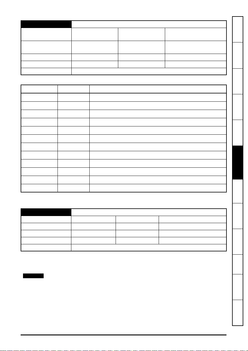
S.10.064 Rx3 Source Type
NOTE
Minimum
Default
0
(Display: Unicast)
0
(Display: Unicast)
Maximum
Units None
11
(Display: Multicast10)
Type 8 Bit User Save Update Rate Read on reset
Display Format None Decimal Places 0
Coding RW, Txt, BU
Value Text Description
0 Unicast Link is unicast to the IP address specified
1 Broadcast Link is broadcast (255.255.255.255)
2 Multicast1 Link is multicast to the IP address (239.255.0.1)
3 Multicast2 Link is multicast to the IP address (239.255.0.2)
4 Multicast3 Link is multicast to the IP address (239.255.0.3)
5 Multicast4 Link is multicast to the IP address (239.255.0.4)
6 Multicast5 Link is multicast to the IP address (239.255.0.5)
7 Multicast6 Link is multicast to the IP address (239.255.0.6)
8 Multicast7 Link is multicast to the IP address (239.255.0.7)
9 Multicast8 Link is multicast to the IP address (239.255.0.8)
10 Multicast9 Link is multicast to the IP address (239.255.0.9)
11 Multicast10 Link is multicast to the IP address (239.255.0.10)
information
Safety
Introduction
Mechanical
installation
installation
Electrical
Getting started
Parameters
and Protocols
Key features
This parameter specifies the type of transmission for the Rx3 link.
S.10.065 Rx3 Timeout
Minimum 0 Maximum 65535
Default 100 Units ms
Type 16 Bit User Save Update Rate Read on reset
Display Format None Decimal Places 0
Coding RW, BU
This parameter specifies the watchdog timer for the Rx3 link. If no cyclic data is received on the
Rx3 link the action taken will be determined by the setting in Rx3 Timeout Action (S.10.066).
It is good system design to allow for some message loss by setting the timeout duration
to be greater than the transmit period by a factor of 2 or more.
SI-Ethernet User Guide 79
Issue: 3
Applications
PC Tools
Security Diagnostics
Glossary of
terms
Index

S.10.066 Rx3 Timeout Action
NOTE
Minimum
Default
Type 8 Bit User Save Update Rate Read on reset
Display Format None Decimal Places 0
Coding RW, Txt, BU
Value Text Description
0 Trip Trip drive with Slx.Er and sub-trip code 106 (Cyclic Timeout)
1 Clear output PLC output parameters will have their values set to zero
2 Hold last Hold the last value in output parameters
Defines the action to be taken for a timeout on the Rx3 link.
S.10.067 Rx3 Timeout Event Dest
Minimum
Default
Type 8 Bit User save Update Rate Read on reset
Display Format None Decimal Places 0
Coding RW, Txt, BU
Value Text Description
0 This slot Trigger module event in this slot
1 Slot 1 Trigger module event in slot 1
2 Slot 2 Trigger module event in slot 2
3 Slot 3 Trigger module event in slot 3
4 Slot 4 Trigger module event in slot 4
0
(Display: Trip)
0
(Display: Trip)
0
(Display: This slot)
0
(Display: This slot)
Maximum
Units None
Maximum
Units None
2
(Display: Hold last)
4
(Display: Slot 4)
This parameter defines the slot in which an event will occur if a cyclic data timeout occurs on the
Rx3 link.
This feature is not yet implemented.
80 SI-Ethernet User Guide
Issue: 3

S.10.068 Rx3 Timeout Event Type
NOTE
Minimum
Default
0
(Display: No Event)
0
(Display: No Event)
Maximum
Units None
4
(Display: Event3)
Type 8 Bit User save Update Rate Read on reset
Display Format None Decimal Places 0
Coding RW, Txt, BU
Value Text Description
0 No Event No event
1 Event Trigger module event
2 Event 1 Trigger module event 1
3 Event 2 Trigger module event 2
4 Event 3 Trigger module event 3
Defines the event to trigger in the given destination, as specified in Rx3 Timeout Event Destination
(S.10.067), if a cyclic data timeout occurs on the Rx3 link.
This feature is not yet implemented.
information
Safety
Introduction
Mechanical
installation
installation
Electrical
Getting started
Parameters
S.10.069 Rx3 Link Status
Minimum
-31
(Display: Disabled)
Maximum
2
(Display: OK sync)
Default None Units None
Type 8 Bit Volatile Update Rate Write on reset
Display Format None Decimal Places 0
Coding RO, Txt, NC, ND, PT
Value Text Description
-31 Disabled Easy Mode protocol is disabled or link number set to 0
-30 VLAN disabled
VLAN is required in order to guarantee timing in
synchronous mode but it is disabled
-29 Reserved 29 Reserved for future use
-28 Reserved 28 Reserved for future use
-27 Reserved 27 Reserved for future use
-26 Reserved 26 Reserved for future use
-25 Reserved 25 Reserved for future use
-24 Reserved 24 Reserved for future use
-23 Reserved 23 Reserved for future use
-22 Invalid DST IP Destination IP address is invalid
SI-Ethernet User Guide 81
Issue: 3
and Protocols
Key features
Applications
PC Tools
Security Diagnostics
Glossary of
terms
Index

Value Text Description
-21 SYNC unsupported
-20 MEC offset Incorrect MEC offset
-19 Invalid tx rate Tx rate must be a factor of 1 second
-18 Too many mapping
-17 Link busy The link specified is busy
-16 Invalid profile The profile is invalid
-15 Invalid mapping The mapped parameter does not exist
-14 Read only param The mapped parameter is read only
-13 Msg mismatch Link number and direction do not match
-12 Msg too long Resulting message is too long
-11 Attrib NA Attribute not available
-10 Attrib RO Attribute is read only
-9 Attrib missing Attribute is missing
-8 Timeout Timeout
-7 In error The specified link is in error state
-6 Link num in use The link number specified is already in use
-5 Not editable The link specified is not editable
-4 Invalid link num An invalid link number was specified
-3 Invalid args Link number / argument zero or invalid
-2 Too many links Maximum number of links has been reached
-1 Out of memory Failed to allocate memory
0 OK Configuration of link successful
1 Not running Ok, not running
2 OK sync Configuration of synchronous link successful
This parameter reports the link’s status if it has been loaded. A Easy Mode Reset (S.10.002) is
required to load any changes.
Sync link does not support mappings to other option
parameters
The number of mapping items exceeds the range
supported
82 SI-Ethernet User Guide
Issue: 3

6.1.5 Menu 11 – Synchronization
S.11.001 Preferred Sync Master
Minimum 0 Maximum 4
Default 1 Units None
Type 8 Bit User Save Update Rate Read on reset
Display Format None Decimal Places 0
Coding RW, BU
This Ethernet interface will be preferred as the grandmaster over others with higher preferred
values or none specified. A value of zero will ensure that the Ethernet interface will not become
grandmaster (making the Ethernet interface act as an IEEE 1588 slave device only). If more than
one Ethernet interface has the same preferred value only one will be chosen as the grandmaster
using the IEEE 1588 BMC algorithm.
The parameter does not guarantee that the Ethernet interface will become grandmaster but a value
of zero guarantees that the Ethernet interface will not become a grandmaster.
S.11.002 Master Clock Domain
Minimum 0 Maximum 3
Default 0 Units
Type 8 Bit User Save Update Rate Read on reset
Display Format None Decimal Places 0
Coding RW, BU
Specifies the clock domain for the Ethernet interface to act as a grandmaster clock.
S.11.005 Grandmaster MAC Address
Minimum
0
(Display: 000000000000)
Maximum
Default None Units None
Type 64 Bit Volatile Update Rate Background write
Display Format MAC Address Decimal Places 0
Coding RO, ND, NC, PT, BU
This parameter displays the MAC address, as a 64-bit hexadecimal value, of the synchronization
grandmaster (if there is a grandmaster).
18446744073709551615
(Display: FFFFFFFFFFFF)
information
Safety
Introduction
Mechanical
installation
installation
Electrical
Getting started
Parameters
and Protocols
Key features
Applications
PC Tools
Security Diagnostics
S.11.006 Sync Jitter From Grandmaster
Minimum -2147483648 Maximum 2147483647
Default None Units ns
Type 32 Bit Volatile Update Rate Written every 500ms
Display Format None Decimal Places 0
Coding RO, ND, NC, PT
This parameter displays the synchronization jitter in nanoseconds. The value is filtered to be
human readable.
SI-Ethernet User Guide 83
Issue: 3
Glossary of
terms
Index

S.11.007 Sync Jitter Threshold
Minimum 500 Maximum 1000000
Default 1000 Units ns
Type 32 Bit User Save Update Rate Read on reset
Display Format None Decimal Places 0
Coding RW, BU
Sets the application tolerable clock jitter in ns from the grandmaster. If Sync Jitter From
Grandmaster (S.11.006) is within the tolerance the local clock is used and Module Synchronised
Flag (S.11.008) is set to 1 and synchronized cyclic data links will be processed.
S.11.008 Module Sync Flag
Minimum
Default
Type 1 Bit Volatile Update Rate Written every 10 ms
Display Format None Decimal Places 0
Coding RO
This parameter displays the module's synchronization status. 1 = Synchronized, 0 = Not
synchronized.
S.11.009 Inhibit Drive Synchronisation
Minimum
Default
Type 1 Bit User Save Update Rate Immediate
Display Format None Decimal Places 0
Coding RW
This parameter controls whether the module synchronizes with the network grandmaster. A value
of On inhibits this.
0
(Display: Off)
0
(Display: Off)
0
(Display: Off)
0
(Display: Off)
Maximum
Units None
Maximum
Units None
1
(Display: On)
1
(Display: On)
S.11.010 PTP Date
Minimum
Default None Units None
Type 32 Bit Volatile Update Rate Written every 500 ms
Display Format Date Decimal Places 0
Coding RO, ND, NC, PT, BU
This parameter displays the current date. If the module has no time source it will display the date
based on its power-up date of 1st January 1970.
0
(Display: 00-00-00)
Maximum
311299
(Display: 31-12-99)
84 SI-Ethernet User Guide
Issue: 3
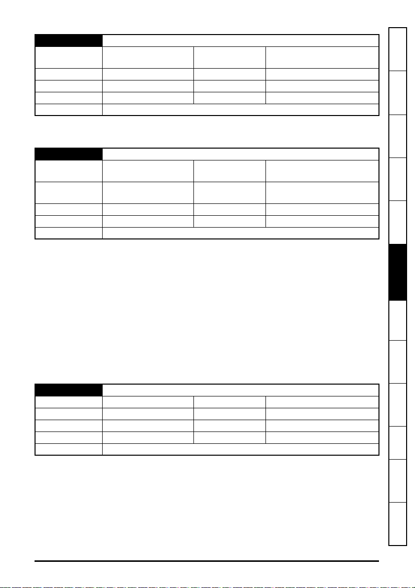
S. 11.0 11 PTP Time
Minimum
0
(Display: 00:00:00)
Maximum
235959
(Display: 23:59:59)
Default None Units None
Type 32 Bit Volatile Update Rate Written every 500 ms
Display Format Time Decimal Places 0
Coding RO, ND, NC, PT, BU
This parameter displays the current time. If the module has no time source it will display the time
based on its power-up time.
S.11.015 PTP Delay Select
Minimum
Default
1
(Display: PTP DELAY)
1
(Display: PTP DELAY)
Maximum
Units None
2
(Display: OFF)
Type 8 Bit User Save Update Rate Read on reset
Display Format None Decimal Places 0
Coding RW, Txt, BU
This parameter can be used for synchronization of the Ethernet interface with the drive control loop.
When this parameter is set to 1 (PTP DELAY), the communication delay measurement mechanism
is peer-to-peer (PTP), this mechanism provides not only the PTP event transmit time information,
but also provides the correction for the propagation delay of the link connected to the port receiving
the PTP event message.
When this parameter is set to 2 (OFF), the PTP messages are disabled, i.e. no PTP delay request
messages will be responded to or initiated. This will prevent the Ethernet interface from
synchronizing with the master.
It is recommended to set this parameter to 2 (OFF) when multiple SI-Ethernet modules or Unidrive
M700 / M702 drives are connected in a "star" topology on an un-managed Ethernet switch. Unmanaged Ethernet switches do not filter the PTP delay response messages, and instead, will
broadcast these to all switch ports which can result in overloading the synchronization master.
information
Safety
Introduction
Mechanical
installation
installation
Electrical
Getting started
Parameters
and Protocols
Key features
Applications
PC Tools
S.11.016 PTP Sync Rate
Minimum -4 Maximum 0
Default -4 Units None
Type 8 Bit User Save Update Rate Read on reset
Display Format None Decimal Places 0
Coding RW
This parameter controls the rate at which PTP Sync frames are sent. The message rate is
determined by raising 2 to the power of this parameter. E.g the default value here of -4 results in
sixteen sync messages per second (2
4
=16).
SI-Ethernet User Guide 85
Issue: 3
Security Diagnostics
Glossary of
terms
Index

S.11.017 In sync window length
Minimum 3 Maximum 255
Default 20 Units Seconds
Type 8 Bit User Save Update Rate Read on reset
Display Format None Decimal Places 0
Coding RW, BU
Duration that the jitter (Synchronisation Jitter From Grandmaster (S.11.006)) must be below the
jitter threshold for before the in sync flag (Module Synchronised Flag (S.11.008)) is set.
For a system the duration depends upon the number of IEEE1588 capable master devices on the
network. To use lower values here the number of devices which are capable of acting as a
synchronization master must be kept as low as possible by setting Preferred Sync Master
(S.11.001) to 0 on all interfaces except those which may be master.
S.11.020 Network Error Count
Minimum 0 Maximum 4294967295
Default None Units None
Type 32 Bit Volatile Update Rate Written every 500 ms
Display Format None Decimal Places 0
Coding RO, ND, NC, PT, BU
The parameter displays a count of network errors since startup. It can be used as an indication of a
problem.
S.11.022 Interoption Sync Status
Minimum
Default
Type 8 Bit Volatile Update Rate Background
Display Format None Decimal Places 0
Coding RO, Txt, ND, NC, PT, BU
0
(Display: MASTER)
0
(Display: MASTER)
Maximum
Units None
2
(Display: INDEPENDENT)
Value Text Description
0 MASTER The module is master but not producing
1 PRODUCER The module is master and producing
2 INDEPENDENT The module is not master
This Interface does not support Slave mode.
86 SI-Ethernet User Guide
Issue: 3

S.11.030 Easy Mode Maximum Network Delay
Minimum 1 Maximum 100
Default 3 Units ms
Type 8 Bit User Save Update Rate Read on reset
Display Format None Decimal Places 0
Coding RW, BU
This parameter defines the allowable network delay (in milliseconds) for the Easy Mode
synchronous transmit cyclic links to arrive at their destination.
S.11.040 Rx1 Late Sync Frame Action
Minimum
Default
1
(Display: Trip)
1
(Display: Trip)
Maximum
Units None
3
(Display: Use)
Type 8 Bit User Save Update Rate Read on reset
Display Format None Decimal Places 0
Coding RW, Txt, BU
information
Safety
Introduction
Mechanical
installation
installation
Electrical
Getting started
Value Text Description
1 Trip Trip drive with Slx.Er and sub-trip code
2 Do not use The data is ignored
3 Use The data is used immediately
This parameter defines the action to be taken when a late synchronized frame is received on the
Rx1 link.
S.11.041 Rx1 Late Sync Frame Dest
Minimum
Default
0
(Display: This slot)
0
(Display: This slot)
Maximum
Units None
4
(Display: Slot 4)
Type 8 Bit User Save Update Rate Read on reset
Display Format None Decimal Places 0
Coding RW, Txt, BU
Value Text Description
0 This slot Trigger module event in this slot
1 Slot 1 Trigger module event in slot 1
2 Slot 2 Trigger module event in slot 2
3 Slot 3 Trigger module event in slot 3
4 Slot 4 Trigger module event in slot 4
Defines the destination (slot) to trigger the event when a late synchronized frame is received on the
Parameters
and Protocols
Key features
Applications
PC Tools
Security Diagnostics
Glossary of
terms
Index
SI-Ethernet User Guide 87
Issue: 3

Rx1 link.
NOTE
NOTE
This feature is not yet implemented.
S.11.042 Rx1 Late Sync Frame Event
Minimum
Default
Type 8 Bit User Save Update Rate Read on reset
Display Format None Decimal Places 0
Coding RW, Txt, BU
Value Text Description
0 No Event No event
1 Event Trigger module event
2 Event1 Trigger module event 1
3 Event2 Trigger module event 2
4 Event3 Trigger module event 3
Defines the event number to trigger in the given destination (slot) when a late synchronized frame
is received on the Rx1 link.
This feature is not yet implemented.
0
(Display: No Event)
0
(Display: No Event)
Maximum
Units None
4
(Display: Event3)
S.11.050 Rx2 Late Sync Frame Action
Minimum
Default
Type 8 Bit User Save Update Rate Read on reset
Display Format None Decimal Places 0
Coding RW, Txt, BU
Value Text Description
1 Trip Trip drive with Slx.Er and sub-trip code 107
2 Do not use The data is ignored
3 Use The data is used immediately
This parameter defines the action to be taken when a late synchronized frame is received on the
Rx2 link.
1
(Display: Trip)
1
(Display: Trip)
Maximum
Units None
3
(Display: Use)
88 SI-Ethernet User Guide
Issue: 3

S.11.051 Rx2 Late Sync Frame Dest
NOTE
NOTE
Minimum
Default
0
(Display: This slot)
0
(Display: This slot)
Maximum
Units None
4
(Display: Slot 4)
Type 8 Bit User Save Update Rate Read on reset
Display Format None Decimal Places 0
Coding RW, Txt, BU
information
Safety
Introduction
Mechanical
installation
Value Text Description
0 This slot Trigger module event in this slot
1 Slot 1 Trigger module event in slot 1
2 Slot 2 Trigger module event in slot 2
3 Slot 3 Trigger module event in slot 3
4 Slot 4 Trigger module event in slot 4
Defines the destination (slot) to trigger the event when a late synchronized frame is received on the
Rx2 link.
This feature is not yet implemented.
S.11.052 Rx2 Late Sync Frame Event
Minimum
Default
0
(Display: No Event)
0
(Display: No Event)
Maximum
Units None
4
(Display: Event3)
Type 8 Bit User Save Update Rate Read on reset
Display Format None Decimal Places 0
Coding RW, Txt, BU
Value Text Description
0 No Event No event
1 Event Trigger module event
2 Event1 Trigger module event 1
3 Event2 Trigger module event 2
4 Event3 Trigger module event 3
installation
Electrical
Getting started
Parameters
and Protocols
Key features
Applications
PC Tools
Security Diagnostics
Glossary of
terms
Defines the event number to trigger in the given destination (slot) when a late synchronized frame
is received on the Rx2 link.
This feature is not yet implemented.
SI-Ethernet User Guide 89
Issue: 3
Index

S.11.060 Rx3 Late Sync Frame Action
NOTE
Minimum
Default
Type 8 Bit User Save Update Rate Read on reset
Display Format None Decimal Places 0
Coding RW, Txt, BU
Value Text Description
1 Trip Trip drive with Slx.Er and sub-trip code 107
2 Do not use The data is ignored
3 Use The data is used immediately
This parameter defines the action to be taken when a late synchronized frame is received on the
Rx3 link.
S.11.061 Rx3 Late Sync Frame Dest
Minimum
Default
Type 8 Bit User Save Update Rate Read on reset
Display Format None Decimal Places 0
Coding RW, Txt, BU
1
(Display: Trip)
1
(Display: Trip)
0
(Display: This slot)
0
(Display: This slot)
Maximum
Units None
Maximum
Units None
3
(Display: Use)
4
(Display: Slot 4)
Value Text Description
0 This slot Trigger module event in this slot
1 Slot 1 Trigger module event in slot 1
2 Slot 2 Trigger module event in slot 2
3 Slot 3 Trigger module event in slot 3
4 Slot 4 Trigger module event in slot 4
Defines the destination (slot) to trigger the event when a late synchronized frame is received on the
Rx3 link.
This feature is not yet implemented.
90 SI-Ethernet User Guide
Issue: 3

S.11.062 Rx3 Late Sync Frame Event
NOTE
Minimum
Default
0
(Display: No Event)
0
(Display: No Event)
Maximum
Units None
4
(Display: Event3)
Type 8 Bit User Save Update Rate Read on reset
Display Format None Decimal Places 0
Coding RW, Txt, BU
Value Text Description
0 No Event No event
1 Event Trigger module event
2 Event1 Trigger module event 1
3 Event2 Trigger module event 2
4 Event3 Trigger module event 3
Defines the event number to trigger in the given destination (slot) when a late synchronized frame
is received on the Rx3 link.
This feature is not yet implemented.
6.1.6 Menu 15 – Modbus
information
Safety
Introduction
Mechanical
installation
installation
Electrical
Getting started
Parameters
S.15.001 Enable
Minimum
Default
0
(Display: Off)
1
(Display: On)
Maximum
Units None
1
(Display: On)
Type 1 Bit User Save Update Rate Background read
Display Format None Decimal Places 0
Coding RW, BU
This parameter is used to enable or disable Modbus master and slave functionality.
S.15.002 Reset
Minimum 0
(Display: Off)
Default 0
(Display: Off)
Maximum
Units None
Type 1 Bit Volatile Update Rate
1
(Display: On)
Background read; written to 0
on initialization
Display Format None Decimal Places 0
Coding RW, NC
This parameter is used to perform a warm reset of the Modbus protocol interface. When set and the
protocol has reset, the parameter will be reset to zero (Off).
SI-Ethernet User Guide 91
Issue: 3
and Protocols
Key features
Applications
PC Tools
Security Diagnostics
Glossary of
terms
Index

S.15.003 Default
Minimum 0
(Display: Off)
Default 0
Type 1 Bit Volatile Update Rate
Display Format None Decimal Places 0
Coding RW, NC
This parameter allows the Modbus protocol to be defaulted to factory settings. This includes all of
the protocol features, configuration, mappings and stored objects.
S.15.004 Modbus Config Error
Minimum 0
Default None Units None
Type 8 Bit Volatile Update Rate
Display Format None Decimal Places 0
Coding RO, Txt, NC, ND, PT, BU
Value Text Description
0 No error No error
1 Port in use Specified port is currently in use by another protocol
2 Timeout event Timeout trigger event location is not valid
3 Num Connections
This parameter will indicate any Modbus configuration errors.
(Display: Off)
(Display: No error)
The Max priority connection is greater than the max
connections
Maximum
Units None
Maximum
1
(Display: On)
On module reset, protocol
interface reset or protocol
enable
3
(Display: Num Connections)
Module reset, Modbus
interface reset or Modbus
interface enable
S.15.005 Modbus Listening Port
Minimum 0 Maximum 65535
Default 502 Units None
Type 16 Bit User Save Update Rate
Display Format None Decimal Places 0
Coding RW, BU
This parameter can be changed from its default port of 502, however it is the user's responsibility to
ensure that a valid port is set.
See Priority Protocol
(S.02.020)
92 SI-Ethernet User Guide
Issue: 3
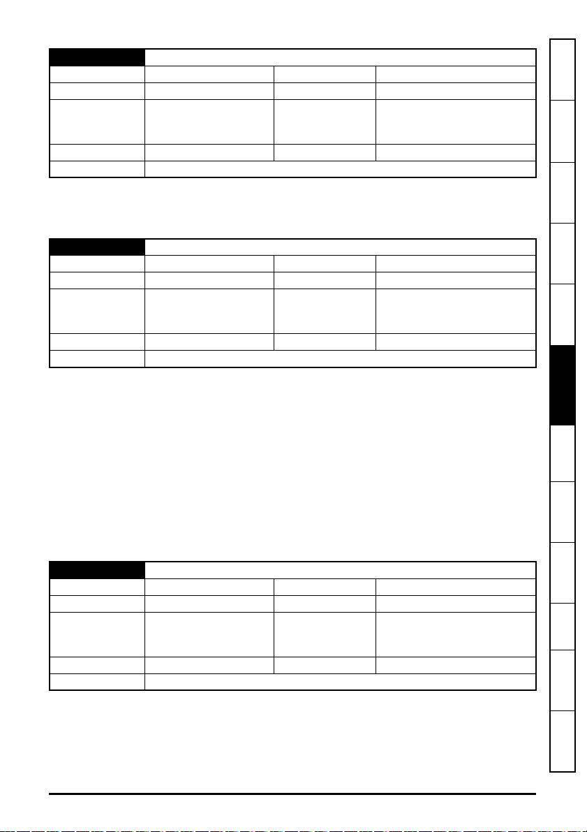
S.15.006 Maximum Connections
Minimum 0 Maximum 4
Default 2 Units None
Module reset, Modbus
Type 8 Bit User Save Update Rate
interface reset or Modbus
interface enable
Display Format None Decimal Places 0
Coding RW, BU
This parameter permits the user to specify the total number of connections that one or more clients
can open with the module at any one time.
S.15.007 Maximum Priority Connections
Minimum 0 Maximum 4
Default 2 Units None
Module reset, Modbus
Type 8 Bit User Save Update Rate
interface reset or Modbus
interface enable
Display Format None Decimal Places 0
Coding RW, BU
This parameter defines how many of the maximum connections specified in Maximum Connections
(S.15.006) can be configured as a priority connection. A connection is accepted into the priority
connections pool if the client's IP address matches one of the values stored in parameters Priority
Connection 1 (S.15.020), Priority Connection 2 (S.15.021), Priority Connection 3 (S.15.022) or
Priority Connection 4 (S.15.023).
The priority connections are permanent and, once made will only be deleted at the request of the
client or due to a communications error.
Any connections not in the priority connections pool are kept in the non-priority connections pool. If
a client attempts to establish a priority connection and all available non-priority connections are in
use, the non-priority connection that has not been used for the longest will be closed to make way
for the new priority connection.
S.15.008 Max Connections Per Client
Minimum 1 Maximum 4
Default 2 Units None
Module reset, Modbus
Type 8 Bit User Save Update Rate
interface reset or Modbus
interface enable
Display Format None Decimal Places 0
Coding RW, BU
This parameter defines the maximum number of priority connections that any one client can
establish. This check is only performed on the connections in the priority connections pool.
information
Safety
Introduction
Mechanical
installation
installation
Electrical
Getting started
Parameters
and Protocols
Key features
Applications
PC Tools
Security Diagnostics
Glossary of
terms
Index
SI-Ethernet User Guide 93
Issue: 3

S.15.009 Modbus Timeout
NOTE
NOTE
Minimum 1 Maximum 10000
Default 100 Units ms
Module reset, Modbus
Type 16 Bit User Save Update Rate
Display Format None Decimal Places 0
Coding RW, BU
This parameter defines the time period in which the Modbus server must receive a message before
any specified action (as defined in Modbus Timeout Action (S.15.010)) is performed. When the
timeout occurs, bit 2 in the module's alarm parameter (Active Alarm Bits (S.00.009)) will be set and
the specified action will be performed.
The timeout is enabled when the server receives its first message.
It is good system design to allow for some message loss by setting the timeout duration
to be greater than the transmit period by a factor of 2 or more.
S.15.010 Modbus Timeout Action
Minimum
Default
Type 8 Bit User Save Update Rate
Display Format None Decimal Places 0
Coding RW, Txt, BU
0
(Display: Trip)
1
(Display: No action)
Maximum
Units None
interface reset or Modbus
interface enable
1
(Display: No action)
Module reset, Modbus
interface reset or Modbus
interface enable
Value Text Description
0 Trip Trip drive and raise error
1 No action
Defines the action when no message is received within the time period specified in Modbus
Timeout (S.15.009).
If a trip is enabled, this will be triggered by the PC Tools software (Unidrive M Connect,
etc). upon scanning the network, or other Modbus masters (HMIs, PLCs etc). using
acyclic read/write commands.
No action
94 SI-Ethernet User Guide
Issue: 3
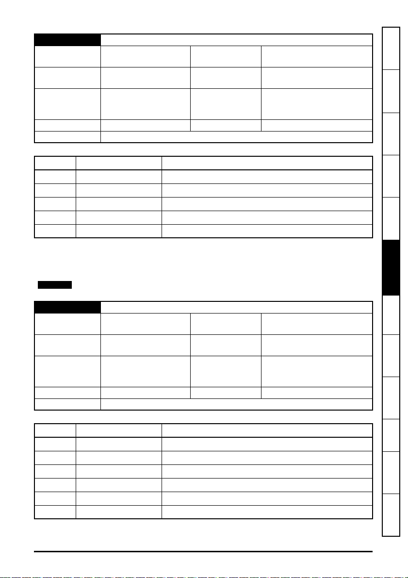
S.15.011 Modbus Timeout Event Dest
NOTE
Minimum
Default
0
(Display: This slot)
0
(Display: This slot)
Maximum
Units None
Type 8 Bit User Save Update Rate
Display Format None Decimal Places 0
Coding RW, Txt, BU
4
(Display: Slot 4)
Module reset, Modbus
interface reset or Modbus
interface enable
information
Safety
Introduction
Mechanical
installation
Value Text Description
0 This slot Trigger event in this slot
1 Slot 1 Trigger event in slot 1
2 Slot 2 Trigger event in slot 2
3 Slot 3 Trigger event in slot 3
4Slot 4
Trigger event in slot 4
Defines the destination slot to trigger the event (defined by Modbus Timeout Event Type
(S.15.012)) when a timeout occurs.
This feature is not yet implemented.
S.15.012 Modbus Timeout Event Type
Minimum
Default
0
(Display: No event)
0
(Display: No event)
Maximum
Units None
5
(Display: Trigger Event 4)
Module reset, Modbus
Type 8 Bit User Save Update Rate
interface reset or Modbus
interface enable
Display Format None Decimal Places 0
Coding RW, Txt, BU
Value Text Description
0 No event No event
1 Trigger Event Trigger module Event
2 Trigger Event 1 Trigger module Event 1
3 Trigger Event 2 Trigger module Event 2
4 Trigger Event 3 Trigger module Event 3
5 Trigger Event 4 Trigger module Event 4
installation
Electrical
Getting started
Parameters
and Protocols
Key features
Applications
PC Tools
Security Diagnostics
Glossary of
terms
Index
Defines the event to trigger when a timeout occurs. Modbus Timeout Event Destination (S.15.011)
SI-Ethernet User Guide 95
Issue: 3

must specify an appropriate consumer (slot option) of the event.
NOTE
This feature is not yet implemented.
S.15.013 Modbus Register Addressing Mode
Minimum
Default
Type 8 Bit User Save Update Rate
Display Format None Decimal Places 0
Coding RW, Txt, BU
Value Text Description
0 Standard (mm x 100) + ppp - mm<=162 and ppp<=99
1 Modified (mm x 256) + ppp - mm<=63 and ppp<=255
Specifies the Modbus register addressing mode.
The standard addressing mode allows menus up to 162 and parameters up to 99 to be accessed,
for any parameter above 99, the modified addressing mode bust be used, however, this mode limits
the highest accessible menu number to 63.
S.15.020 Priority Connection 1
Minimum
Default
Type 32 Bit User Save Update Rate
Display Format IP Address Decimal Places 0
Coding RW, BU
This parameter specifies an IP address for priority connection 1.
0
(Display: Standard)
0
(Display: Standard)
0
(Display: 0.0.0.0)
0
(Display: 0.0.0.0)
Maximum
Units None
Maximum
Units None
1
(Display: Modified)
Module reset, Modbus
interface reset or Modbus
interface enable
4294967295
(Display: 255.255.255.255)
Module reset, Modbus
interface reset or Modbus
interface enable
96 SI-Ethernet User Guide
Issue: 3

S.15.021 Priority Connection 2
Minimum
Default
0
(Display: 0.0.0.0)
0
(Display: 0.0.0.0)
Maximum
Units None
Type 32 Bit User Save Update Rate
Display Format IP Address Decimal Places 0
Coding RW, BU
This parameter specifies an IP address for priority connection 2.
S.15.022 Priority Connection 3
Minimum
Default
0
(Display: 0.0.0.0)
0
(Display: 0.0.0.0)
Maximum
Units None
Type 32 Bit User Save Update Rate
Display Format IP Address Decimal Places 0
Coding RW, BU
This parameter specifies an IP address for priority connection 3.
S.15.023 Priority Connection 4
Minimum
Default
0
(Display: 0.0.0.0)
0
(Display: 0.0.0.0)
Maximum
Units None
Type 32 Bit User Save Update Rate
Display Format IP Address Decimal Places 0
Coding RW, BU
This parameter specifies an IP address for priority connection 4.
4294967295
(Display: 255.255.255.255)
Module reset, Modbus
interface reset or Modbus
interface enable
4294967295
(Display: 255.255.255.255)
Module reset, Modbus
interface reset or Modbus
interface enable
4294967295
(Display: 255.255.255.255)
Module reset, Modbus
interface reset or Modbus
interface enable
information
Safety
Introduction
Mechanical
installation
installation
Electrical
Getting started
Parameters
and Protocols
Key features
Applications
PC Tools
Security Diagnostics
SI-Ethernet User Guide 97
Issue: 3
Glossary of
terms
Index

6.1.7 Menu 20 – EtherNet/IP Set-up
Synchronous
Cyclic Links
Cyclic Links
Background
Task
500 µs
O
P
T
I
O
N
S
D
R
I
V
E
>=500 µs
Network
>=1 ms
The Ethernet interface supports the EtherNet/IP protocol and conforms to the EtherNet/IP
adaptation of the Common Industrial Protocol (CIP) Specification. This is the same upper-layer
protocol and object model as used in DeviceNet.
The Ethernet interface will operate as a slave device and the following functionality is supported.
• Variable length input assembly object (instance 100) with consistency for up to 32
parameters
• Variable length output assembly object (instance 101) with consistency for up to 32
parameters
• User selectable RPI timeout action
• Identity object (class 0x01)
• Motor data object (class 0x28)
• Control supervisor object (class 0x29)
• AC/DC Drive object (class 0x2A)
• Control Techniques objects (classes 0x64 to 0x69)
• Explicit (non-cyclic) access to parameters
EtherNet/IP server port
The Ethernet interface uses the standard server port 44818 (0xAF12) for EtherNet/IP
communications, this is fixed and cannot be changed.
Parameter Update Rate
Parameters are exchanged over the network. The value exchanged over the network must be
exchanged with the drive or option parameter. The rate of data exchange differs for drive and option
destinations.
The diagram below depicts the update cycles used within the Ethernet interface. CIP assembly
mappings being exchanged with the drive will be updated at the background task rate. This rate
(Background cycles per second (S.09.008)) varies with the load on the Ethernet interface; Easy
Mode non-synchronized data exchange also takes place in the background task.
98 SI-Ethernet User Guide
Issue: 3

S.20.001 Enable EtherNet/IP
NOTE
Minimum
Default
0
(Display: Off)
1
(Display: On)
Maximum
Units None
1
(Display: On)
Type 1 Bit User Save Update Rate Background read
Display Format None Decimal Places 0
Coding RW, BU
This parameter is used to enable or disable EtherNet/IP slave functionality.
If either Input Assembly Object Size (S.20.020) or Output Assembly Object Size
(S.20.021) is a non zero value then the available mappings will still be consumed even
if the Ethernet/IP functionality is disabled.
information
Safety
Introduction
Mechanical
installation
installation
Electrical
S.20.002 Reset
Minimum
Default
0
(Display: Off)
0
(Display: Off)
Maximum
Units None
Type 1 Bit Volatile Update Rate
1
(Display: On)
Background read; written to 0
on initialization
Display Format None Decimal Places 0
Coding RW, NC
This parameter is used to perform a warm reset of the protocol interface. When set and the protocol
has reset, the parameter will be reset to zero (Off).
S.20.003 Default
Minimum 0
Default 0
(Display: Off)
(Display: Off)
Maximum
Units
1
(Display: On)
None
On module reset, protocol
Type 1 Bit Volatile Update Rate
interface reset or protocol
enable
Display Format None Decimal Places 0
Coding RW, NC
This parameter allows the EtherNet/IP protocol to be defaulted to factory settings. This includes all
of the protocol features, configuration, mappings and stored objects.
Getting started
Parameters
and Protocols
Key features
Applications
PC Tools
Security Diagnostics
Glossary of
terms
Index
SI-Ethernet User Guide 99
Issue: 3

S.20.004 Configuration error
Minimum 0
(Display: No error)
Default None Units None
Type 8 Bit Volatile Update Rate Background
Display Format None Decimal Places 0
Coding RO, Txt, ND, NC, PT, BU
Value Text Description
0 No error No error
1 RPI event dst RPI timeout event destination not valid
2 RPI event type RPI timeout event type not valid
3 IDLE event dst PLC IDLE event destination not valid
4 IDLE event type PLC IDLE event type not valid
5 Input mapping Input mapping parameter not valid
6 Output mapping Output mapping parameter not valid
7 In cons trig pr Input consistency trigger parameter not valid
8 Out cons trig pr
This parameter is used to display the error code if an EtherNet/IP configuration error occurs.
S.20.007 Cyclic Data Transfers / s
Minimum 0 Maximum 65535
Default None Units Messages/s
Type 16 Bit Volatile Update Rate Background
Display Format None Decimal Places 0
Coding RO, ND, NC, PT, BU
This parameter shows the EtherNet/IP cyclic data transfer rate.
Output consistency trigger parameter not valid
Maximum
8
(Display: Out cons trig pr)
100 SI-Ethernet User Guide
Issue: 3
 Loading...