

Page 1
Unidrive M100 to M400 Size 4
WARNING
WARNING
WARNING
1
UL Conduit Box Installation Sheet
1 Safety information
Follow the instructions
The mechanical and electrical installation instructions must be adhered to. Any questions or doubt should be referred to the supplier of the
equipment. It is the responsibility of the owner or user to ensure that the installation of the drive and any external option unit, and the way
in which they are operated and maintained, comply with any applicable legislation, regulation, and code of practice in the country in which
the equipment is used.
Competence of the installer
The drive must be installed by qualified personnel who are familiar with the requirements for safety and EMC. The installer is responsible
for ensuring that the end product or system complies with all the relevant laws in the country where it is to be used.
2 Introduction
This document covers the UL conduit box mounting instructions for
Unidrive M100 to M400, frame size 4 drives and derivatives.
When fitted, the drive meets the requirement for Type 1 protection
according to UL50 and UL50E.
Type 1 enclosures are intended for indoor use only. They provide a
degree of protection to personnel against incidental contact with the
enclosed equipment and a degree of protection against falling debris.
The following items are supplied in the kit:
Table 2-1 Contents of the kit (CT part number: 3470-0102)
Description Image Qty
Conduit box x 1
Conduit cover x 1
3 Installation
Stored charge
The drive contains capacitors that remain charged to a
potentially lethal voltage after the AC and / or DC power
supply has been disconnected. If the drive has been
energized, the power supply must be isolated at least ten
minutes before work may continue.
Normally, the capacitors are discharged by an internal
resistor. Under certain, unusual fault conditions, it is possible
that the capacitors may fail to discharge, or be prevented
from being discharged by a voltage applied to the output
terminals. If the drive has failed in a manner that causes the
display to go blank immediately, it is possible the capacitors
will not be discharged. In this case, consult Control
Techniques or their authorized distributor.
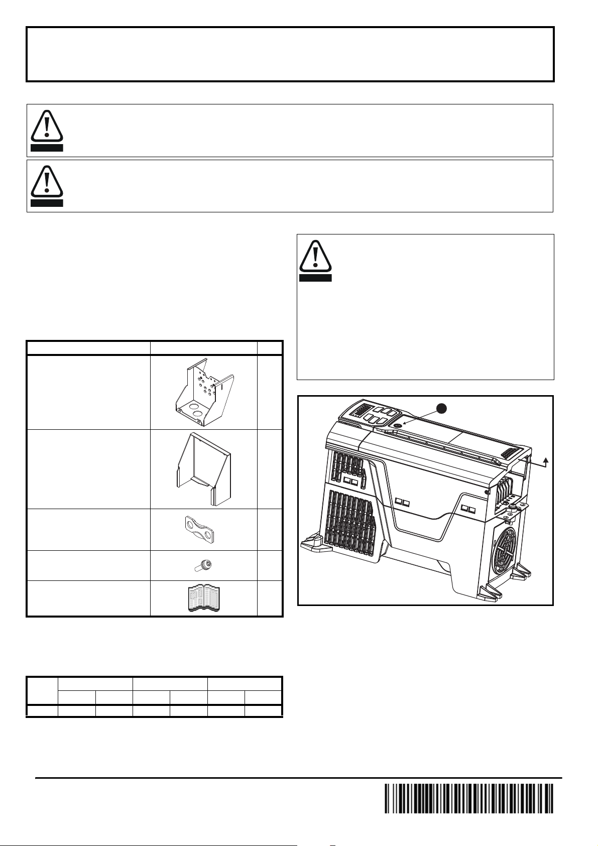
Figure 3-1 Removing the drive terminal cover
Grounding clamp x 3
M4 x 16 torx taptite screw x 8
UL conduit box installation sheet x 1
The installed conduit kit does not change the width or depth of the drive.
However, this conduit kit will add 103 mm (4.0 in) to the height of the
drive.
Table 2-2 shows the combined drive and conduit box dimensions.
Table 2-2 Dimensions
Frame
size
4 362 14.3 115 4.5 175 6.9
HWD
mm in mm in mm in
• Use flat blade screwdriver to remove the drive terminal cover by
turning the cover release 30° counter clockwise and sliding the
cover downward (1).
0478-0384-01
Page 2
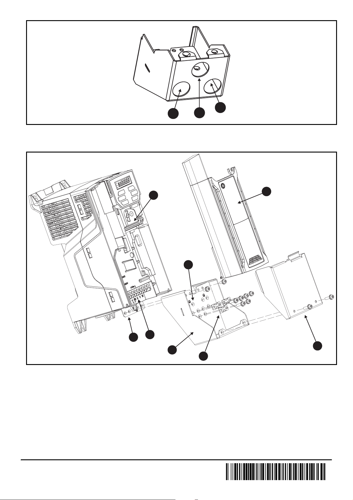
Figure 3-2 Holes for conduit fittings
1
3
2
1
2
3
4
6
8
7
5
• Using the pilot holes provided on the bottom of the conduit box, drill holes for appropriately sized conduit fittings. Motor cables with motor ground
wire (1), supply cables with supply ground wire (2), and control/communication cables (if applicable) (3) need to be run in separate conduits.
Figure 3-3 Installation of conduit connection box
• Attach the conduit box (1) to the grounding bar (2) using the four M4 x 8 screws provided with the drive. Maximum recommended torque is
1.5 N m (13 lb in).
• Attach the conduit fittings to the conduit box holes; run the conduit to the drive.
• Run the motor cables (U,V, W) and motor ground wire through the back-right conduit. Connect the wires to the motor connector (U,V,W) (3).
Maximum recommended torque for screw terminals is 1.4 N m (12 lb in).
• Run the supply cables (L1,L2,L3) and supply ground wire through the back-left conduit. Connect the wires to the supply connector (L1,L2,L3) (3).
Maximum recommended torque for screw terminals is 1.4 N m (12 lb in).
• Fasten M4 ring terminals, suitable for the wire size, to the supply ground and motor ground wires. Connect the ground wires to the conduit box
grounding locations using M4 x 16 screws (4). Maximum recommended torque is 1.5 N m (13 lb in).
• Run the control cables through the front-center conduit. Connect the control cables to the control connector as required (5). Maximum
recommended torque for control terminals is 0.2 N m (2 lb in).
• Secure all cables and cable shielding to the conduit box using the grounding clamps and M4 x 16 screws (6). Maximum recommended torque is
1.5 N m (13 lb in).
• Replace the drive terminal cover by laying it on the drive and sliding it upward (7).
• Attach the conduit box cover to the conduit box using two M4 x 16 screws (8). Maximum recommended torque is 1.5 N m (13 lb in).
0478-0384-01
 Loading...