

Nidec Unidrive M600, Unidrive M70X, Unidrive F300, Unidrive H300, Unidrive E200 Mounting Installation Sheet
...
Unidrive M600-M70X, F300, H300, E200 & E300 Size 3
WARNING
WARNING
Through-panel Mounting Installation Sheet
1 Safety information
Follow the instructions
The mechanical and electrical installation instructions must
be adhered to. Any questions or doubt should be referred to
the supplier of the equipment. It is the responsibility of the
owner or user to ensure that the installation of the drive and
any external option unit, and the way in which they are
operated and maintained, comply with the requirements of
the Health and Safety at Work Act in the United Kingdom or
applicable legislation and regulations and codes of practice in
the country in which the equipment is used.
Competence of the installer
The drive must be installed by qualified personnel who are
familiar with the requirements for safety and EMC. The
installer is responsible for ensuring that the end product or
system complies with all the relevant laws in the country
where it is to be used.
2 Introduction
This document covers through-panel mounting instructions for Unidrive
M600 / M70X, F300, H300, E200 & E300 Size 3 drives. The standard
drive is rated to IP20 pollution degree 2 (dry, non-conductive
contamination only, NEMA 1), however it is possible to configure the
device to achieve IP65 rating (NEMA 12). This is done by sealing the
heat sink vent at the rear of the heatsink by installing the high IP insert
as illustrated in Figure 3-1. Some current derating is required, and
reference should be made to the drive’s User Guide for current derating
information.
The following items are supplied in the kit bag:
Table 2-1 Contents of the bag (CT Part Number: 3470-0053-00)
Description Image Qty
3 Instructions
3.1 Installing the high IP insert
Figure 3-1 Installing the high IP insert
Through panel mounting gasket x 1
Through panel securing brackets x 2
High IP insert x 1
Through panel mounting
installation sheet
The following items are included in the kit boxes 3470-0038 and
3470-0042, either of which can be supplied with the drive.
Table 2-2 Additional items required
Description Image Qty
Frame 3 mounting brackets x 2
x 1
1. To install the high IP insert, first unclip the baffle plate using a flat
bladed screwdriver inserted under the slot as shown in Figure 3-1
(1).
2. Pull the hinged baffle plate down to expose the ventilation hole.
Install the high IP insert into the ventilation hole in the heatsink (2).
Ensure the high IP insert is securely installed by pressing it firmly
into place.
3. Close the hinged baffle plate by rotating it upwards until the clips on
the baffle plate are secure within the slots in the drive chassis as
shown in (3).
0478-0017-03
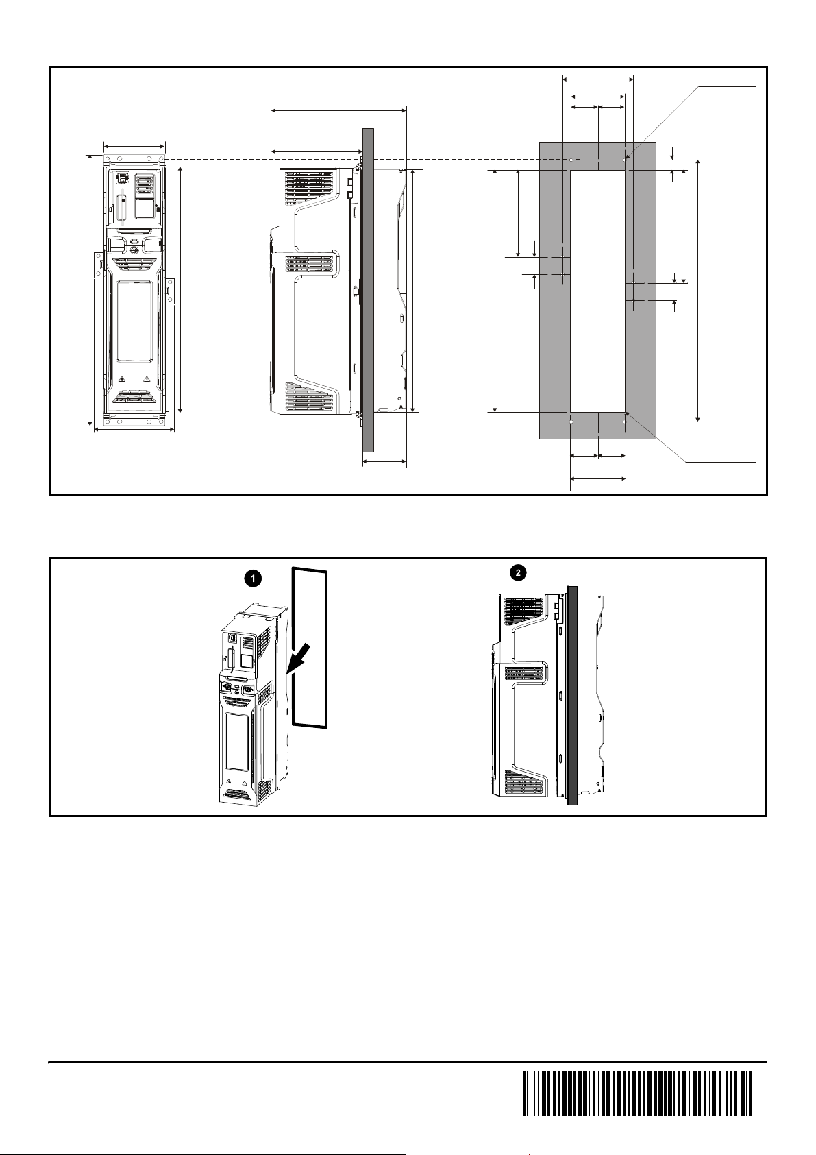
3.2 Preparing the backplate
359 mm
(14.13 in)
83 mm (3.27 in)
365 mm
(14.37 in)
400 mm
(15.74 in)
200 mm (7.87 in)
67 mm
(2.64 in)
134 mm (5.28 in)
109 mm (4.29 in)
97 mm (3.82 in)
36.5 mm
(1.44 in)
5.20 mm (0.21 in)
x 8 holes
73 mm (2.87 in)
36.5 mm
(1.44 in)
15 mm
(0.59 in)
129 mm (5.08 in)26 mm (1.02 in)168 mm (6.61 in)359 mm (14.13 in)389 mm (15.32 in)
26 mm (1.02 in)
Radius 1.0 mm (0.04 in)
38 mm
(1.50 in)
38 mm
(1.50 in)
76 mm (2.99 in)
Figure 3-2 Backplate mounting detail
Prepare the backplate in accordance with the mounting dimensions shown in Figure 3-2.
3.3 Preparing for installation
Figure 3-3 Installing the gasket
1. Install the main gasket with the kit provided as shown (1).
2. The image on the right shows the assembled drive and gasket (2).
0478-0017-03

3.4 Installing the drive
Figure 3-4 Installing the lower mounting bracket
Figure 3-6 Securing the upper mounting bracket
Loosely secure the lower mounting bracket to the mounting plate using
suitable M5 fasteners as shown in Figure 3-4.
Figure 3-5 Inserting the drive through the backplate and securing
to the backplate
Locate the upper mounting bracket into the drive chassis upper
mounting slots and secure the drive to the mounting bracket using
suitable M5 fasteners. Make sure the M5 fasteners are fully secured at
the top and bottom of the mounting plate before proceeding further.
Figure 3-7 Installing the through panel mounting brackets
Insert the drive through the cut-out in the mounting plate and engage the
drive chassis mounting slots on the lower mounting bracket ensuring
that the drive is supported at all times until secured firmly.
0478-0017-03
Install the through panel securing brackets (x2) into the drive chassis,
and secure them to the backplate using suitable M5 fasteners. Check to
be sure that the gasket has not become trapped under the mounting
brackets before fully tightening the M5 fasteners.
 Loading...