


Power Installation Guide
Freestanding
Drives
DFS Series High Power Drive
Cubicles
Part Number: 0478-0573-02
Is
sue: 2

Original Instructions
For the purposes of compliance with the EU Machinery Directive 2006/42/EC, the English version of this manual is
the Original Instructions. Manuals in other languages are Translations of the Original Instructions.
Documentation
Manuals are available to download from the following locations: http://www.drive-setup.com/ctdownloads
The information contained in this manual is believed to be correct at the time of printing and does not form part of
any contract. The manufacturer reserves the right to change the specification of the product and its performance,
and the contents of the manual, without notice.
Warranty and Liability
In no event and under no circumstances shall the manufacturer be liable for damages and failures due to misuse,
abuse, improper installation, or abnormal conditions of temperature, dust, or corrosion, or failures due to operation
outside the published ratings. The manufacturer is not liable for consequential and incidental damages. Contact the
supplier of the drive for full details of the warranty terms.
Environmental policy
Control Techniques Ltd operates an Environmental Management System (EMS) that conforms to the International
Standard ISO 14001.
Further information on our Environmental Policy can be found at: http://www.drive-setup.com/environment
Restriction of Hazardous Substances (RoHS)
The products covered by this manual comply with European and International regulations on the Restriction of
Hazardous Substances including EU directive 2011/65/EU and the Chinese Administrative Measures for Restriction
of Hazardous Substances in Electrical and Electronic Products.
Disposal and Recycling (WEEE)
When electronic products reach the end of their useful life, they must not be disposed of along
with domestic waste but should be recycled by a specialist recycler of electronic equipment.
Control Techniques products are designed to be easily dismantled into their major component
parts for efficient recycling. The majority of materials used in the product are suitable for
recycling.
Product packaging is of good quality and can be re-used. Large products are packed in wooden
crates. Smaller products are packaged in strong cardboard cartons which have a high recycled
fibre content. Cartons can be re-used and recycled. Polythene, used in protective film and bags
for wrapping the product, can be recycled. When preparing to recycle or dispose of any product
or packaging, please observe local legislation and best practice.
REACH legislation
EC Regulation 1907/2006 on the Registration, Evaluation, Authorisation and restriction of Chemicals (REACH)
requires the supplier of an article to inform the recipient if it contains more than a specified proportion of any
substance which is considered by the European Chemicals Agency (ECHA) to be a Substance of Very High
Concern (SVHC) and is therefore listed by them as a candidate for compulsory authorisation.
Further information on our compliance with REACH can be found at: http://www.drive-setup.com/reach
Registered Office
Nidec Control Techniques Ltd
The Gro
Newtown
Powys
SY16 3BE
UK
Registered in England and Wales. Company Reg. No. 01236886.

Copyright
The contents of this publication are believed to be correct at the time of printing. In the interests of a commitment to
a policy of continuous development and improvement, the manufacturer reserves the right to change the
specification of the product or its performance, or the contents of the guide, without notice.
All rights reserved. No parts of this guide may be reproduced or transmitted in any form or by any means, electrical
or mechanical including photocopying, recording or by an information storage or retrieval system, without
permission in writing from the publisher.
Copyright © July 2019 Nidec Control Techniques Ltd

Contents
1 Safety information .....................................................................................10
1.1 Warnings, Cautions and Notes ..............................................................................10
1.2 General information ................................................................................................10
1.3 Responsibility .........................................................................................................10
1.4 Compliance with regulations ..................................................................................10
1.5 Electrical hazards ...................................................................................................11
1.6 Stored electrical charge .........................................................................................11
1.7 Mechanical hazards ...............................................................................................11
1.8 Access to equipment ..............................................................................................11
1.9 Environmental limits ...............................................................................................11
1.10 Hazardous environments .......................................................................................11
1.11 Motor ......................................................................................................................12
1.12 Mechanical brake control .......................................................................................12
1.13 Adjusting parameters .............................................................................................12
1.14 Electromagnetic compatibility (EMC) ..................................................................... 12
1.15 Safe Torque Off ......................................................................................................12
2 Product information ..................................................................................13
2.1 Introduction ............................................................................................................ 13
2.2 Model number ........................................................................................................13
2.3 Nameplate description ...........................................................................................15
2.4 Ratings ...................................................................................................................16
2.5 Cubicle features .....................................................................................................18
3 Mechanical installation .............................................................................20
3.1 Safety information ..................................................................................................20
3.2 Planning the installation .........................................................................................22
3.3 Control terminal cover removal ..............................................................................24
3.4 Cubicle Dimensions ...............................................................................................26
3.5 Terminal size and torque settings ..........................................................................27
3.6 Routine maintenance .............................................................................................28
3.7 Cooling fan replacement ........................................................................................28
3.8 Storage ...................................................................................................................29
4 Electrical installation .................................................................................30
4.1 Power connections .................................................................................................31
4.2 Ground connections ...............................................................................................32
4.3 AC Supply requirements ........................................................................................34
4.4 Operation on IT (ungrounded) supplies .................................................................35
4.5 Ground connections ...............................................................................................36
4.6 Upstream protection ...............................................................................................36
4.7 Motor requirements ................................................................................................39
4.8 Output short circuit protection ................................................................................ 39
4.9 Motor overload protection ......................................................................................40
4.10 Motor cables ...........................................................................................................41
4.11 High-capacitance / reduced diameter cables .........................................................42
4.12 Output contactor .....................................................................................................43
4.13 Safe Torque Off ......................................................................................................43
4.14 Braking ...................................................................................................................43
4.15 Ground leakage ......................................................................................................44
4.16 Use of a residual current device (RCD) .................................................................44
4.17 Starts per hour .......................................................................................................44
4.18 Start-up time ...........................................................................................................44
4.19 Motor winding voltage ............................................................................................44
4.20 Star/ Delta motor operation ....................................................................................45
4.21 External 24 V DC Supplies .....................................................................................45
4.22 Electromagnetic compatibility .................................................................................46
DFS1/DFS2 Power Installation Guide
Issue Number: 2

5 Technical data ............................................................................................ 53
5.1 Drive technical data ............................................................................................... 53
DFS1/DFS2 Power Installation Guide
Issue Number: 2

EU Declaration of Conformity
1. Product range
Drive Free Standing (DFS).
2. Name and address of the manufacturer
Nidec Netherlands B.V.
Kubus 155
3364 DG Sliedrecht
Postbus 300
3360 AH Sliedrecht
Netherlands
3. Responsibility
This declaration is issued under the sole responsibility of the manufacturer.
4. Object of the declaration
Model No. Interpretation Nomenclature aaaa - DFS b c d e f g h i
aaaa Drive module range Industrial drive = M700, M701, M702. Process drive = F300
DFS Format DFS = Drive Free Standing
b Number of drives 1, 2
c Current rating step Any alphanumeric character: 1 – 9, A – Z
d Voltage rating 4 = 400 V, 6 = 690 V
e World Region E = Europe, A = Americas
f Input circuit N = Rectifier - Single 6 pulse
g Input switch S = Load Switch (Standard)
h Enclosure rating A = IP23 – Air Cooled, C = IP54 – Air Cooled
iOptions
5. Declaration
The object of the declaration is in conformity with the relevant European Union harmonisation
legislation.
Low Voltage Directive (2014/35/EU)
Electromagnetic Compatibility Directive (2014/30/EU)
Restriction of Hazardous Substances Directive (2011/65/EU).
6. References to the relevant harmonised standards used
The variable speed drive products listed above have been designed and manufactured in
accordance with the following European harmonised standards:
EN 61800-5-1:2007+A1:2017
EN 61800-3: 2018
EN 61000-6-2: 2019
The model number may be followed by any combination of 10 digits
denoting customer options. The options do not affect the ratings.
Adjustable speed electrical power drive systems - Part 5-1: Safety requirements Electrical, thermal and energy
Adjustable speed electrical power drive systems - Part 3: EMC requirements and
specific test methods
Electromagnetic compatibility (EMC) - Part 6-2: Generic standards - Immunity for
industrial environments
6 DFS1/DFS2 Power Installation Guide
Issue Number: 2

7. Responsible person
Jon Holman-White
Vice President of Research and Development
Nidec Control Techniques Ltd
Date: 20th May 2019
Newtown, Powys, UK.
These electronic drive products are intended to be used with appropriate motors, controllers,
electrical protection components and other equipment to form complete end products or
systems. Compliance with safety and EMC regulations depends upon installing and
configuring drives correctly, including using the specified input filters.
The drives must be installed only by professional installers who are familiar with
requirements for safety and EMC. Refer to the Product Documentation. An EMC data sheet is
available giving detailed information. The assembler is responsible for ensuring that the
product or system complies with all the relevant laws in the country where it is to be used.
DFS1/DFS2 Power Installation Guide 7
Issue Number: 2

EU Declaration of Conformity (Machinery Directive)
1. Product model
Unidrive-M and derivative products incorporating a Safe Torque Off (STO) function when used as a
safety component of a machine.
2. Name and address of the manufacturer
Nidec Control Techniques Ltd, The Gro, Newtown, Powys, SY16 3BE, UK
Registered in England and Wales, Company Reg. No. 0126885
Telephone: 00 44 1686 612300
E-mail: marketing.control techniques@mail.nidec.com
Web: www.controltechniques.com
3. This declaration is issued under the sole responsibility of the manufacturer.
4. Object of the declaration
Model No. Interpretation Nomenclature aaaa - bbc ddddde
aaaa Basic series
bb Frame Size 03, 04, 05, 06, 07, 08, 09, 10, 11
c VoltageRating 1 = 100 V, 2 = 200 V, 4 = 400 V, 5 = 575 V, 6 = 690 V
ddddd Current Rating Example 01000 = 100 A
e Drive Format
The model number may be followed by additional characters that do not affect the ratings.
5. The object of the declaration is in conformity with the relevant European Union
harmonisation legislation.
Machine Directive (2006/42/EC)
Electromagnetic Compatibility Directive (2014/30/EU)
M600, M700, M701, M702, M708, M709, M750, M751, M753, M754, F300,
H300, E200, E300, HS70, HS71, HS72, M000, RECT
A = 6P Rectifier + Inverter with internal choke, D = Inverter, E = 6P Rectifier +
Inverter, T = 12P Rectifier + Inverter (external choke)
EC type examination has been carried out by the following notified body:
TUV Rheinland Industries Service GmbH EC type-examination certificate numbers:
AM Grauen Stein
D-51105 Köln 01/205/5270.02/17 dated 2017-08-28
Germany
Notified body identification number: 0035
Only the Safe Torque Off function may be used for a safety function of a machine. None of the other
functions of the drive may be used to carry out a safety function. The object of the declaration is in
conformity with the relevant European Union harmonisation legislation.
8 DFS1/DFS2 Power Installation Guide
Issue Number: 2

6. References to the relevant harmonised standards used
The variable speed drive products listed above have been designed and manufactured in
accordance with the following European harmonized standards:
EN 61800-5-2:2016
EN 61800-5-1:2016
(in extracts)
EN 61800-3: 2004+A1:2012
EN ISO 13849-1:2015
EN 62061:2005 + AC:2010 +
A1:2013 + A2:2015
IEC 61508 Parts 1 - 7:2010
Adjustable speed electrical power drive systems - Part 5-2: Safety requirements Functional
Adjustable speed electrical power drive systems - Part 5-1: Safety requirements Electrical, thermal and energy
Adjustable speed electrical power drive systems - Part 3: EMC requirements and
specific test methods
Safety of Machinery, Safety-related parts of control systems, General principles
for design
Safety of Machinery, Functional safety of safety related electrical, electronic and
programmable electronic control systems
Functional safety of electrical/electronic/programmable electronic safety-related
systems
7. Signed for and behalf of:
Person authorised to complete the technical file:
DoC authorised by:
P. Knight
Conformity Engineer
Jon Holman-White
Director of Research and
Development
Date:
19th November 2018
Place:
Newtown, Powys, UK
DFS1/DFS2 Power Installation Guide 9
Issue Number: 2

1 Safety information
WARNING
CAUT ION
NOTE
1.1 Warnings, Cautions and Notes
A Warning contains information which is essential for avoiding a safety hazard.
A Caution contains information which is necessary for avoiding a risk of damage to the
product or other equipment.
A Note contains information, which helps to ensure correct operation of the product.
1.2 General information
This guide applies to products which control electric motors either directly (drives) or indirectly
(controllers, option modules and other auxiliary equipment and accessories). In all cases the hazards
associated with powerful electrical drives are present, and all safety information relating to drives and
associated equipment must be observed.
Specific warnings are given at the relevant places in this guide.
Drives and controllers are intended as components for professional incorporation into complete
systems. If installed incorrectly they may present a safety hazard. The drive uses high voltages and
currents, carries a high level of stored electrical energy, and is used to control equipment which can
cause injury. Close attention is required to the electrical installation and the system design to avoid
hazards either in normal operation or in the event of equipment malfunction. System design,
installation, commissioning/start-up and maintenance must be carried out by personnel who have the
necessary training and competence. They must read this safety information and this guide carefully.
1.3 Responsibility
It is the responsibility of the installer to ensure that the equipment is installed correctly with regard to
all instructions given in this guide. They must give due consideration to the safety of the complete
system, so as to avoid the risk of injury both in normal operation and in the event of a fault or of
reasonably foreseeable misuse.
The manufacturer accepts no liability for any consequences resulting from inappropriate, negligent or
incorrect installation of the equipment.
1.4 Compliance with regulations
The installer is responsible for complying with all relevant regulations, such as national wiring
regulations, accident prevention regulations and electromagnetic compatibility (EMC) regulations.
Particular attention must be given to the cross-sectional areas of conductors, the selection of fuses
or other protection, and protective ground (earth) connections.
This guide contains instructions for achieving compliance with specific EMC standards.
All machinery to be supplied within the European Union in which this product is used must comply
with the following directives:
2006/42/EC Safety of machinery.
2014/30/EU: Electromagnetic Compatibility.
10 DFS1/DFS2 Power Installation Guide
Issue Number: 2

1.5 Electrical hazards
The voltages used in the drive can cause severe electrical shock and/or burns, and could be lethal.
Extreme care is necessary at all times when working with or adjacent to the drive. Hazardous voltage
may be present in any of the following locations:
• AC and DC supply cables and connections
• Output cables and connections
• Many internal parts of the drive, and external option units
Unless otherwise indicated, control terminals are single insulated and must not be touched.
The supply must be disconnected by an approved electrical isolation device before gaining access to
the electrical connections.
The STOP and Safe Torque Off functions of the drive do not isolate dangerous voltages from the
output of the drive or from any external option unit.
The drive must be installed in accordance with the instructions given in this guide. Failure to observe
the instructions could result in a fire hazard.
1.6 Stored electrical charge
The drive contains capacitors that remain charged to a potentially lethal voltage after the AC supply
has been disconnected. If the drive has been energized, the AC supply must be isolated at least ten
minutes before work may continue.
1.7 Mechanical hazards
Careful consideration must be given to the functions of the drive or controller which might result in a
hazard, either through their intended behaviour or through incorrect operation due to a fault. In any
application where a malfunction of the drive or its control system could lead to or allow damage, loss
or injury, a risk analysis must be carried out, and where necessary, further measures taken to reduce
the risk - for example, an over-speed protection device in case of failure of the speed control, or a
fail-safe mechanical brake in case of loss of motor braking.
With the sole exception of the Safe Torque Off function, none of the drive functions must be
used to ensure safety of personnel, i.e. they must not be used for safety-related functions.
The Safe Torque Off function may be used in a safety-related application. The system designer is
responsible for ensuring that the complete system is safe and designed correctly according to the
relevant safety standards.
The design of safety-related control systems must only be done by personnel with the required training
and experience. The Safe Torque Off function will only ensure the safety of a machine if it is correctly
incorporated into a complete safety system. The system must be subject to a risk assessment to
confirm that the residual risk of an unsafe event is at an acceptable level for the application.
Safety information
Product information Mechanical installation Electrical installation Technical data
1.8 Access to equipment
Access must be restricted to authorized personnel only. Safety regulations which apply at the place
of use must be complied with.
1.9 Environmental limits
Instructions in this guide regarding transport, storage, installation and use of the equipment must be
complied with, including the specified environmental limits. This includes temperature, humidity,
contamination, shock and vibration. Drives must not be subjected to excessive physical force.
1.10 Hazardous environments
The equipment must not be installed in a hazardous environment (i.e. a potentially explosive
environment).
DFS1/DFS2 Power Installation Guide 11
Issue Number: 2

1.11 Motor
The safety of the motor under variable speed conditions must be ensured.
To avoid the risk of physical injury, do not exceed the maximum specified speed of the motor.
Low speeds may cause the motor to overheat because the cooling fan becomes less effective,
causing a fire hazard. The motor should be installed with a protection thermistor. If necessary, an
electric forced vent fan should be used.
The values of the motor parameters set in the drive affect the protection of the motor. The default
values in the drive must not be relied upon. It is essential that the correct value is entered in the
Motor Rated Current parameter.
1.12 Mechanical brake control
Any brake control functions are provided to allow well co-ordinated operation of an external brake
with the drive. While both hardware and software are designed to high standards of quality and
robustness, they are not intended for use as safety functions, i.e. where a fault or failure would result
in a risk of injury. In any application where the incorrect operation of the brake release mechanism
could result in injury, independent protection devices of proven integrity must also be incorporated.
1.13 Adjusting parameters
Some parameters have a profound effect on the operation of the drive. They must not be altered
without careful consideration of the impact on the controlled system. Measures must be taken to
prevent unwanted changes due to error or tampering.
1.14 Electromagnetic compatibility (EMC)
Installation instructions for a range of EMC environments are provided in the relevant Power Installation
Guide. If the installation is poorly designed or other equipment does not comply with suitable standards
for EMC, the product might cause or suffer from disturbance due to electromagnetic interaction with
other equipment. It is the responsibility of the installer to ensure that the equipment or system into
which the product is incorporated complies with the relevant EMC legislation in the place of use.
1.15 Safe Torque Off
The Unidrive M700 / M701 has a single channel Safe Torque Off, whereas the Unidrive M702 has a
dual channel STO. The Safe Torque Off function provides a means for preventing the drive from
generating torque in the motor, with a very high level of integrity. It is suitable for incorporation into a
safety system for a machine. It is also suitable for use as a conventional drive enable input.
Machinery Applications
The Safe Torque Off function has been independently assessed by Notified Body, TüV Rheinland for
use as a safety component of a machine:
Prevention of unintended motor operation: The safety function “Safe Torque Off” can be used in
applications up to Cat 4, PL e according to EN ISO 13849-1, SIL 3 according to EN 61800-5-2/
EN 62061/ IEC 61508 and in lift applications according to EN 81-1 and EN 81-2.
TüV certificate No. 01.205/5270.02/17
Date: 28-08-2017
For further details consult the M700, M701 M702 Control User Guide, CT part No. 0478-0353-02.
12 DFS1/DFS2 Power Installation Guide
Issue Number: 2

2 Product information
Parallel dr ives
Curre nt Step Volts Circuit Brake
Drive range
Format
Drive Specification
Configuation
Input
swi t ch
Enclosure
rating
Cubicle options code
M70x
DFS194ENS
A
10000000
Drive range:
M70x Industrial dr ive
F300 Process driv e
Free standing drive
Number of parallel dr ives in
a cubicle
Current rating step
Supply voltage:
4=400 V; 6=690 V
World region:
E= Europe
A = Americas
Input circuit
N = Rectifier Single 6 pulse
Input switch:
S= Load sw itch
Enclosure rating:
A= IP23
B= IP44 - Air inlet grill filter s
C= IP54 - Filters, through panel
mounted heatskink s, roof mounted
exhaust grill
W= Water cooled heat exchanger
(IP55)
Options (See
table 2-1)
2.1 Introduction
This guide provides the information necessary to install the following cubicle models:
DFS 1
DFS 2
This guide focuses on the cubicle power section, for example: electrical installation of the supply /
motor cables and mechanical installation of the cubicle.
The drives are housed in a compact IP23 or IP54 enclosure. A water-cooled option is available.
A wide range of options are available including EMC filters and kWh meters.
This guide focuses on the drive power section, for example: electrical installation of the supply /
motor cables and mechanical installation of the drive.
For information about the cubicle control section, for example: parameter set up information, control
and encoder connections please refer to the M700, M701 M702 Control User Guide CT part
No. 0478-0353.
2.2 Model number
The model number for the DFS product range is formed as illustrated below:
Figure 2-1 Model numbers
Safety information
Product information
Mechanical installation Electrical installation Technical data
Table 2-1 Options
IP23 A = IP23 (Standard)
IP55 - Water Cooled W = Water cooled heat exchanger
EMC Filter N/A
Remove internal EMC filter Remove internal EMC filter N/A
Remove MOV protection Remove MOV protection N/A
Speed-controlled roof fan Cabinet temperature controlled roof fanN/A
Plinth 200 mm Standard plinth is 100 mm N/A
DFS1/DFS2 Power Installation Guide 13
Issue Number: 2
Option Description Selection Rule
Choose A, B or WIP54 B = IP54

Option Description Selection Rule
NOTE
180° door hinges Alternative hinge for improved access N/A
Cylinder lock with key Extra cubicle security N/A
A - Undervoltage release coil 230 VAC Main switch with 230 VAC (MN)
B - Undervoltage release coil 24 VAC Main switch with 24 VAC (MN)
C - Shunt trip voltage release coil 230 VAC Main switch with 230 VAC (MX)
D - Shunt trip voltage release coil 24 VAC Main switch with 24 VAC (MX)
A - kWh meter Conventional (IP54) with CTs (non MID)
B - kWh meter Modbus RTU with CTs (non MID)
C - kWh meter Profibus
(Not available with 690 V)
D - kWh meter Ethernet with CTs (non MID)
kWh meter pulse contacts
24 V back-up supply wiring
Auxiliary contacts main switch
Rittal integrated empty incomer 400 mm
Back plate empty incomer N/A
Emergency stop push button Red push button on door N/A
Air Freight Additional Packaging for DFS1
and 1
with CTs (non MID)
In combination with A, B, C or D kWh
meters
Provision for external 24 V backup power
supply
Supply and wiring of two auxiliary contacts
on main switch
Includes plinth 100 mm both cable plates
mounted to DFS
Pallet, Straps, Carton and Labour N/A
If release coil
needed, choose A,
B, C or D
If kWh meter
needed, choose A,
B, C or D
See description
N/A
N/A
N/A
When ordering a DFS drive, options can be selected using an on-line configurator tool. Alternatively,
contact the local Control Techniques drives sales office for further information. The standard options
are summarised in Table 2-1.
Cubicle options code is generated by an on-line configurator.
14 DFS1/DFS2 Power Installation Guide
Issue Number: 2

2.3 Nameplate description
DFS model number
Serial number
Unidrive M model number
Input
Voltage/frequency/current
Ouput
Voltage/frequency/current
Normal/heavy duty
power rating
Figure 2-2 Typical drive rating label
Figure 2-3 Auxiliary supply rating label
Safety information
Product information
Mechanical installation Electrical installation Technical data
Figure 2-4 Upstream protection warning label
DFS1/DFS2 Power Installation Guide 15
Issue Number: 2

2.4 Ratings
NOTE
NOTE
NOTE
Table 2-2 400 V and 690 V ratings
Output
power at
400 V
(ND/HD)
kW
Model
Supply
voltage
V
Supply
current
A
Output
current
A
xxxx-DFS1G4EN 400 155 155/134 75/55 100/100 172
xxxx-DFS1H4EN 400 177 184/157 90/75 150/125 202
xxxx-DFS1J4EN 400 232 221/200 110/90 150/150 243
xxxx-DFS1K4EN 400 267 266/224 132/110 200/150 293
xxxx-DFS1L4EN 400 332 320/270 160/132 250/200 352
xxxx-DFS1M4EN 400 397 361/320 200/160 300/250 397
xxxx-DFS1N4EN 400 449 437/377 225/185 350/300 481
xxxx-DFS1P4EN 400 492 487/417 250/200 400/350 536
xxxx-DFS1Q4EN 400 539 507/464 280/250 450/400 558
xxxx-DFS2L4EN 400 631 640/540 320/264 500/400 704
xxxx-DFS2M4EN 400 657 722/640 400/320 600/500 794
xxxx-DFS2N4EN 400 853 874/754 450/370 700/600 962
xxxx-DFS2P4EN 400 935 974/834 500/400 800/700 1072
xxxx-DFS2Q4EN 400 1024 1014/928 560/500 900/800 1116
xxxx-DFS166EN 690 83 86/63 75/55 100/75 95
xxxx-DFS176EN 690 104 108/86 90/75 125/100 119
xxxx-DFS186EN 690 149 125/104 110/90 150/125 138
xxxx-DFS196EN 690 171 155/131 132/110 175/150 171
xxxx-DFS1A6EN 690 202 172/150 160/132 200/175 189
xxxx-DFS1B6EN 690 225 197/178 185/160 250/200 217
xxxx-DFS1C6EN 690 256 225/210 200/185 250/250 248
xxxx-DFS1D6EN 690 302 275/238 250/200 300/250 303
xxxx-DFS1E6EN 690 329 305/263 280/250 400/300 336
xxxx-DFS2A6EN 690 384 344/300 320/264 400/350 378
xxxx-DFS2B6EN 690 427 394/356 370/320 500/400 434
xxxx-DFS2C6EN 690 486 450/420 400/370 500/500 496
xxxx-DFS2D6EN 690 574 550/476 500/400 600/500 606
xxxx-DFS2E6EN 690 625 610/526 560/500 800/600 672
Motor power
at 460 V
(ND/HD)
hp
Peak Output
current
A
xxxx denotes F300, M700, M701 or M702.
Output current and power ratings are shown as Normal Duty/ Heavy Duty For an explanation of
Normal and Heavy-Duty ratings, refer to the M700, M701, M702 Control User Guide (CT part
number: 0478-0353).
M70x data based on Heavy Duty ratings. F300 data based on Normal Duty ratings.
16 DFS1/DFS2 Power Installation Guide
Issue Number: 2

M70x data based on Heavy Duty ratings. F300 data based on Normal Duty ratings.
NOTE
NOTE
Table 2-3 Protective ground cable ratings
Input phase conductor size Minimum ground conductor size
> 35 mm² Half of the cross-sectional area of the input phase conductor
Typical short-term overload limits
The maximum percentage overload limit changes depending on the selected motor. Variations in
motor rated current, motor power factor and motor leakage inductance all result in changes in the
maximum possible overload. Typical values are shown in the table below:
Table 2-4 Typical overload limits
Operating mode RFC from cold
Normal Duty overload with motor rated
current = drive rated current
Heavy Duty overload with motor rated
current = drive rated current
110 % for 165 s 110 % for 9 s 110 % for 165 s 110 % for 9 s
175 % for 42 s 175 % for 5 s 150 % for 60 s 150 % for 7 s
RFC from
100 %
Generally, the drive rated current is higher than the matching motor rated current allowing a higher
level of overload than the default setting.
The time allowed in the overload region is proportionally reduced at very low output frequency on
some drive ratings.
Open loop
from cold
Open loopfrom
100 %
Safety information
Product information
Mechanical installation Electrical installation Technical data
The maximum overload level which can be attained is independent of the speed.
Output current
The continuous output current ratings given on the rating label are for maximum 35 °C (95 °F),
1000 m altitude and 2 kHz switching frequency. Derating is required for higher switching frequencies,
ambient temperatures > 40 °C (104 °F). For further information, refer to Chapter 5.1 Drive technical
data on page 53.
Input current
The input current is affected by the supply voltage and impedance. The input current given on the
rating label is the typical input current and is stated for a balanced supply.
DFS1/DFS2 Power Installation Guide 17
Issue Number: 2

2.5 Cubicle features
Figure 2-5 Features of the size 1 cubicle
18 DFS1/DFS2 Power Installation Guide
Issue Number: 2

Figure 2-6 Features of the size 2 cubicle
NOTE
Safety information
Product information
Mechanical installation Electrical installation Technical data
E-plan drawings, which contain parts lists and electrical schematic diagrams for all the DFS frame
sizes are available on Support Suite.
DFS1/DFS2 Power Installation Guide 19
Issue Number: 2

3 Mechanical installation
WARNING
WARNING
WARNING
WARNING
WARNING
CAUT ION
3.1 Safety information
Follow the instructions
The mechanical and electrical installation instructions must be adhered to. Any questions
or doubt should be referred to the supplier of the equipment. It is the responsibility of the
owner or user to ensure that the installation of the drive and any external option unit, and
the way in which they are operated and maintained, comply with the requirements of the
Health and Safety at Work Act in the United Kingdom or applicable legislation and
regulations and codes of practice in the country in which the equipment is used.
Stored charge
The drive contains capacitors that remain charged to a potentially lethal voltage after the
AC supply has been disconnected. If the drive has been energized, the AC supply must
be isolated at least ten minutes before work may continue.
Normally, the capacitors are discharged by an internal resistor. Under certain, unusual
fault conditions, it is possible that the capacitors may fail to discharge, or be prevented
from being discharged by a voltage applied to the output terminals. If the drive has failed
in a manner that causes the display to go blank immediately, it is possible the capacitors
will not be discharged. In this case, consult Nidec Industrial Automation or their authorized
distributor.
Competence of the installer
The drive must be installed by professional assemblers who are familiar with the
requirements for safety and EMC. The assembler is responsible for ensuring that the end
product or system complies with all the relevant laws in the country where it is to be used.
Enclosure
The drive is intended to be mounted in an enclosure which prevents access except by
trained and authorized personnel, and which prevents the ingress of contamination. It is
designed for use in an environment classified as pollution degree 2 in accordance with
IEC 60664-1. This means that only dry, non-conducting contamination is acceptable.
Hazardous areas
The drive must not be installed in a classified hazardous area unless it is installed in an
approved enclosure and the installation in certified.
Protection of equipment prior to installation
If the equipment is not to be installed immediately, it must be protected from moisture and
dust.
The equipment is delivered wrapped in plastic to protect it from mechanical damage. It is
recommended that wrapping is left in place until installation.
20 DFS1/DFS2 Power Installation Guide
Issue Number: 2

3.1.1 Lifting and Handling
NOTE
WARNING
Use the lifting eyebolts attached
to the top of the enclosure
Arrow indicates the lifting point/
direction of the enclosure
Insert the shackles into the
eyebolts. Ensure the angle of
each lifting rope is ≥ 45°
WARNING
The information in this section is also provided on a laminated sheet fixed to the outside of the
enclosure. It is intended to be read by the personnel responsible for lifting, handling and transporting
the drive.
Lifting and handling
Always lift the drive by the lifting lugs.
The drives are not supplied with lifting lugs. These must be fitted to the top of the enclosure
by the installer.
Insert shackles into the eye bolts. Ensure that the angle of each lifting rope is greater than
45°, as shown in Figure 3-1.
Figure 3-1 Lifting the cubicle
Safety information Product information
Mechanical installation
The cubicle is disproportionally heavy at the top and must be properly secured to prevent
it from overbalancing and falling during installation.
When transporting the equipment by fork lift truck, place the cubicle on a rigid pallet and
secure it in place.
Multiple bayed enclosures cannot be transported this way.
The maximum weight of the cubicles are shown in Table 3-1.
Table 3-1 Maximum cubicle weight
Size Model kg lb
DFS1 All variants 300 661
DFS2 All variants 720 1587
DFS1/DFS2 Power Installation Guide 21
Issue Number: 2
Electrical installation Technical data

Figure 3-2 Transporting the cubicle
NOTE
3.2 Planning the installation
The following considerations must be made when planning the installation:
3.2.1 Access
Access must be restricted to authorized personnel only. Safety regulations which apply at the place
of use must be complied with.
3.2.2 Environmental protection
The DFS drives are offered with a choice of two Ingress Protection (IP) ratings:
IP23: Protection against fingers or similar objects larger than 12.5 mm. Protection from water falling
as a spray at any angle up to 60° from the vertical.
IP54: Protection against ingress of dust is not entirely prevented but must not enter in quantities that
may interfere with operation of the equipment. Protection from water splashing against the enclosure
from any direction.
The drive enclosure protects the internal components from:
• Moisture, including dripping water or spraying water and condensation. An anti-condensation
heater may be required, which must be switched off when the drive is running.
• Contamination with electrically conductive material
• Contamination with any form of dust which may restrict the fan, or impair airflow over various
components
• Temperature beyond the specified operating and storage ranges
• Corrosive gasses
During installation it is recommended that the vents on the drive are covered to prevent debris
(e.g. wire off-cuts) from entering the cubicle.
3.2.3 Cooling
The heat produced by the internal components must be removed without its specified operating
temperature being exceeded. Note that a sealed enclosure gives much reduced cooling compared
with a ventilated one and may need to be larger and/or use internal air circulating fans.
3.2.4 Fire protection
The enclosure is classified as a Fire Enclosure within the meaning of IEC 62109-1. It surrounds the
internal parts and is intended to minimize the spread of fire or flaming materials from within.
22 DFS1/DFS2 Power Installation Guide
Issue Number: 2

3.2.5 Electromagnetic compatibility
WARNING
CAUT ION
Variable speed drives are powerful electronic circuits which can cause electromagnetic interference if
not installed correctly with careful attention to the layout of the wiring.
Some simple routine precautions can prevent disturbance to typical industrial control equipment.
If it is necessary to meet strict emission limits, or if it is known that electromagnetically sensitive
equipment is located nearby, then full precautions must be observed. In-built into the drive, is an
internal EMC filter, which reduces emissions under certain conditions. If these conditions are
exceeded, then the use of an external EMC filter may be required at the drive inputs, which must be
located very close to the drives. Space must be made available for the filters and allowance made for
carefully segregated wiring. For further details relating to EMC, refer to the EMC data sheet,
CT part number 0478-0575-01.
3.2.6 Electrical safety
The installation must be safe under normal and fault conditions. Electrical installation instructions are
given in Chapter 4 Electrical installation on page 30.
Hot surfaces
Care must be taken when opening the cubicle door as some components may be very hot
to touch even after the 10 minutes discharge time.
Safety information Product information
Component IP ratings
The internal cubicle components are rated to IP20. This must be taken into consideration
when the doors are opened.
Mechanical installation
Electrical installation Technical data
DFS1/DFS2 Power Installation Guide 23
Issue Number: 2

3.3 Control terminal cover removal
NOTE
3.3.1 Removing the drive control terminal cover
The Unidrive M drive control terminals are fitted with a terminal cover. The terminal cover must be
removed to gain access to the control terminals.
Refer to the relevant control user guide for details on the control terminal layout, functionality and
option modules.
Figure 3-3 Location and identification of terminal cover
24 DFS1/DFS2 Power Installation Guide
Issue Number: 2
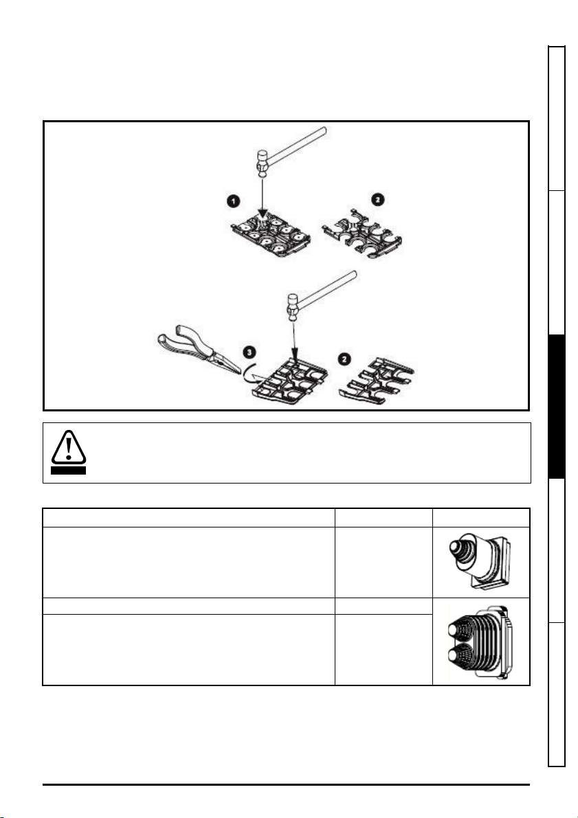
3.3.2 Removal of finger-guard breakouts
WARNING
To remove the finger-guards place the finger-guard on a flat solid surface and knock out the finger
guards using a hammer. The breakout can be removed by grasping it with pliers and twisting it off.
Once all break-outs have been removed, remove any flash/sharp edges. See Figure 3-4.
Figure 3-4 Removing the finger-guard breakouts
Grommets
Grommets should be installed in the power terminal apertures to help restrict the spread
of fire in the event of a major internal failure.
Safety information Product information
Mechanical installation
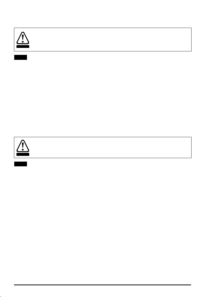
Table 3.5 Grommet kits
Drive module size Par number Image
Frame size 8 - kit of 8 single entry grommets 3470-0089
Frame size 8- kit of 8 double entry grommets 3470-0090
Frame size 9, 10 and 11 – kit of 8 double entry grommets 3470-0107
DFS1/DFS2 Power Installation Guide 25
Issue Number: 2
Electrical installation Technical data

3.4 Cubicle Dimensions
Figure 3-6 Dimensions of the DFS1 cubicle
Cubicle
type
DFS1 400 600 600 725 2000 100 or 200 180 180 65
Width Depth Height Plinth height Roof fan height
a
IP23 IP44 IP54 IP23 IP23 IP44 IP54
bc
d
e
26 DFS1/DFS2 Power Installation Guide
Issue Number: 2

3.4.1 Cubicle dimensions
Figure 3-7 Dimensions of the DFS2 cubicle
Safety information Product information
Mechanical installation
Cubicle
type
DFS2 1200 600 600 725 2000 100 or 200 180 180 65
Width Depth Height Plinth height Roof fan height
a
IP23 IP44 IP54 IP23 IP23 IP44 IP54
bc
d
e
3.5 Terminal size and torque settings
Table 3-2 Drive control and relay terminal data
Terminal Connection size Torque setting
AC supply M10 lug 15 Nm (11.1 lb ft)
Drive module Motor output terminals 1 x M10 x 17 AF Nut 15 Nm (11.1 lb ft)
Earth (Ground) terminals 1 x M10 x 17 AF Nut 15 Nm (11.1 lb ft)
Output sharing choke bus bar
connections
Mains isolation switch 3 x M10 x 27.5 AF Nut 20 Nm (14.76 lb ft)
Control and user relay terminals Plug-in terminal block 0.5 Nm (0.4lbft)
DFS1/DFS2 Power Installation Guide 27
Issue Number: 2
1 x 11mm hole 10Nm (7.38lbft)
Electrical installation Technical data

Stored charge
WARNING
The drive contains capacitors that remain charged to a potentially lethal voltage after the
AC supply has been disconnected. If the drive has been energized, the AC supply must
be isolated at least ten minutes before work may continue.
Normally, the capacitors are discharged by an internal resistor. Under certain, unusual
fault conditions, it is possible that the capacitors may fail to discharge, or be prevented
from being discharged by a voltage applied to the output terminals. If the drive has failed
in a manner that causes the display to go blank immediately, it is possible the capacitors
will not be discharged. In this case, consult Nidec Industrial Automation or their authorized
distributor.
3.6 Routine maintenance
The cubicle should be installed in a cool, clean, well ventilated location. Contact of moisture and dust
with the drive should be prevented.
Regular checks of the following should be carried out to ensure drive / installation reliability are
maximized:
Environment
Ambient temperature Ensure the enclosure temperature remains at or below maximum specified.
Dust
Moisture Ensure the cubicle shows no signs of condensation.
Enclosure
Enclosure door filters Ensure filters are not blocked and that air is free to flow.
Electrical
Screw connections Ensure all screw terminals remain tight.
Crimp terminals
Cables Check all cables for signs of damage.
Check that the drive module heatsinks and cooling fans are not gathering dust.
This includes the roof fans and the filters in the door. The lifetime of the lfan is reduced
in dusty environments.
Ensure all crimp terminals remains tight – check for any discoloration which could
indicate overheating.
3.7 Cooling fan replacement
Refer to the drive module Power Installation guides for details of how to replace the drive module
cooling fans in the event of failure.
28 DFS1/DFS2 Power Installation Guide
Issue Number: 2

3.8 Storage
CAUT ION
The storage conditions are as follows:
Storage temperature: 5 °C to 55 °C
Maximum humidity: 95 % non-condensing at 35 °C.
Maximum storage time: 2 years.
Storage time
Electrolytic capacitors in any electronic product have a finite storage period after which
they require reforming or replacing.
The drive modules have a maximum storage time of 2 years, after which the equipment
should be powered up for a minimum of 1 hour to reform the capacitors. The equipment
can then be stored for a further 2 years.
Safety information Product information
Mechanical installation
DFS1/DFS2 Power Installation Guide 29
Issue Number: 2
Electrical installation Technical data

4 Electrical installation
WARNING
WARNING
WARNING
WARNING
WARNING
WARNING
Electric shock risk
The voltages present in the following locations can cause severe electric shock and may
be lethal:
AC supply cables and connections
DC and brake cables, and connections
Output cables and connections
Many internal parts of the drive, and external option units
Unless otherwise indicated, control terminals are single insulated and must not be
touched.
Isolation device
The AC and / or DC power supply must be disconnected from the drive using an approved
isolation device before any cover is removed from the drive or before any servicing work
is performed.
STOP function
The STOP function does not remove dangerous voltages from the drive, the motor or any
external option units.
Safe Torque Off function
The Safe Torque Off function does not remove dangerous voltages from the drive,
the motor or any external option units.
Stored charge
The drive contains capacitors that remain charged to a potentially lethal voltage after the
AC and / or DC power supply has been disconnected. If the drive has been energized,
the AC and / or DC power supply must be isolated at least ten minutes before work may
continue. Normally, the capacitors are discharged by an internal resistor. Under certain,
unusual fault conditions, it is possible that the capacitors may fail to discharge or be
prevented from being discharged by a voltage applied to the output terminals. If the drive
has failed in a manner that causes the display to go blank immediately, it is possible the
capacitors will not be discharged. In this case, consult Nidec Industrial Automation or
their authorized distributor.
Permanent magnet motors
Permanent magnet motors generate electrical power if they are rotated, even when the
supply to the drive is disconnected. If that happens then the drive will become energized
through its motor terminals. If the motor load is capable of rotating the motor when the
supply is disconnected, then the motor must be isolated from the drive before gaining
access to any live parts.
30 DFS1/DFS2 Power Installation Guide
Issue Number: 2

4.1 Power connections
Figure 4-1 DFS1 Power connections
Safety information Product information Mechanical installation Electrical installation Technical data
DFS1/DFS2 Power Installation Guide 31
Issue Number: 2

Figure 4-2 DFS2 power connections
WARNING
4.2 Ground connections
The ground loop impedance must conform to the requirements of local safety regulations.
The drive must be grounded by a connection capable of carrying the prospective fault
current until the protective device (fuse, etc.) disconnects the AC supply.
The ground connections must be inspected and tested at appropriate intervals.
The cubicle must be connected to the system ground of the AC supply. The ground wiring must
conform to local regulations and codes of practice.
The supply and motor ground connections are made using the ground busbar shown in Figure 4-3
and Figure 4-4.
32 DFS1/DFS2 Power Installation Guide
Issue Number: 2

Figure 4-3 DFS1 ground connections
Safety information Product information Mechanical installation Electrical installation Technical data
DFS1/DFS2 Power Installation Guide 33
Issue Number: 2

Figure 4-4 DFS2 ground connections
4.3 AC Supply requirements
The DFS drives are suitable for use on any supply type: TN-S, TN-C-S, TT and IT. The AC supply
should comply with the limits shown in Table 4-1.
34 DFS1/DFS2 Power Installation Guide
Issue Number: 2

Table 4-1 AC supply specification
WARNING
WARNING
Parameter Rating
Voltage 380 V to 480 V ±10 % 500 V to 690 V ±10 %
No of phases 3
Supply frequency 45 to 66 Hz
Supply type TN-S, TN-C-S, TT, IT
Overvoltage category
Impulse voltage rating 4 kV for 400 V, 6 kV for 690 V drives
Maximum supply imbalance
1. For installations where the equipment is installed at the origin of the supply, additional over-voltage
suppression (transient voltage surge suppression) must be provided to reduce the overvoltage category
from OVC IV to OVC III.
OVC III (according to IEC 60664-1)
2 % negative phase sequence (equivalent to 3 % voltage imbalance between
phases).
1
Auxiliary transformer tap setting
Before powering up the drive, it is important to check that the auxiliary transformer tapping
has been set correctly. Wrong selection could result in damage to transformer and the roof
fans.
4.4 Operation on IT (ungrounded) supplies
Operation on IT (ungrounded) supplies
Unusual hazards can occur on IT (ungrounded supplies).
A ground (earth) fault in the incoming supply has no effect. The drive will continue to run.
However, the phase to phase voltage will appear between two of the supply terminals and
ground (Earth). On a 690 V supply, this will stress the insulation.
A ground (earth) fault in the motor circuit may not cause the drive to trip. If the motor
is required to continue to run with a ground fault in its circuit, then an input isolating
transformer must be provided. If an EMC filter is required, it must be located on the
primary side of the isolating transformer.
The following measures must be taken:
Additional, independent motor ground fault protection must be provided.
EMC filters must not be used
The internal EMC filter inside the drive module must be disconnected
1. Disconnection of the internal EMC filter on frame size 11E is only possible at the factory. This must be
specified when ordering.
1
.
Safety information Product information Mechanical installation Electrical installation Technical data
DFS1/DFS2 Power Installation Guide 35
Issue Number: 2

4.5 Ground connections
WARNING
WARNING
WARNING
Ground connections
The equipment must be grounded (earthed). The wiring must conform to local regulations
and codes of practice. This is the responsibility of the installer.
The ground loop impedance must conform to the requirements of local safety regulations.
The grounded connection must be capable of carrying the prospective fault current until
the protective device (fuse, etc.) disconnects the AC supply.
The cross-sectional area of the Ground (Earth) conductor must be not less than half the
cross-sectional area of the input phase conductors.
The ground connections must be inspected and tested at appropriate intervals.
Electrochemical corrosion of grounding terminals
Ensure that grounding terminals are protected against corrosion, for example caused
by condensation.
4.6 Upstream protection
It is necessary to install upstream fuses to protect the supply cables from overload and
fire. The recommended fuse types and current ratings are marked on the Upstream
Protection label fixed to the outside of the drive enclosure (See Figure 4-5).
Upstream fuse ratings for all DFS drives are shown in Table 4-2. The fuse voltage rating
must be suitable for the drive supply voltage.
Figure 4-5 Upstream protection label
36 DFS1/DFS2 Power Installation Guide
Issue Number: 2

Table 4-2 Upstream fuse ratings
WARNING
NOTE
Model
xxxx-DFS1G4EN 1 155 160 gG 100
xxxx-DFS1H4EN 1 177 200 gG 100
xxxx-DFS1J4EN 1 232 250 gG 100
xxxx-DFS1K4EN 1 267 315 gG 100
xxxx-DFS1L4EN 1 332 400 gG 100
xxxx-DFS1M4EN 1 397 500 gG 100
xxxx-DFS1N4EN 1 449 500 gG 100
xxxx-DFS1P4EN 1 492 630 gG 100
xxxx-DFS1Q4EN 1 539 630 gG 100
xxxx-DFS2L4EN 2 631 800 gG 100
xxxx-DFS2M4EN 2 657 800 gG 100
xxxx-DFS2N4EN 2 853 1000 gG 70
xxxx-DFS2P4EN 2 935 1000 gG 70
xxxx-DFS2Q4EN 2 1024 1250 gG 40
xxxx-DFS166EN 1 83 100 gG 80
xxxx-DFS176EN 1 104 125 gG 80
xxxx-DFS186EN 1 149 160 gG 80
xxxx-DFS196EN 1 171 200 gG 80
xxxx-DFS1A6EN 1 202 250 gG 80
xxxx-DFS1B6EN 1 225 250 gG 80
xxxx-DFS1C6EN 1 256 315 gG 80
xxxx-DFS1D6EN 1 302 315 gG 80
xxxx-DFS1E6EN 1 329 400 gG 100
xxxx-DFS2A6EN 2 384 400 gG 100
xxxx-DFS2B6EN 2 427 500 gG 100
xxxx-DFS2C6EN 2 486 500 gG 100
xxxx-DFS2D6EN 2 574 630 gG 100
xxxx-DFS2E6EN 2 625 800 gG 100
No. of drive
modules fitted
Input current
A
Upstream
fuse rating
A
Fuse type
Short circuit
current rating
Safety information Product information Mechanical installation Electrical installation Technical data
Supply cable sizes
Cables sizes must comply with local wiring regulations and are the responsibility of the
installer. The cable sizes shown in Table 4-3 and Table 4-4 are for guidance only.
The current-carrying capacity of cables is affected by the mounting method and grouping.
A larger cable size may be required to avoid excessive temperature or voltage drop.
The cable sizes in Table 4-3 and Table 4-4 are calculated using IEC60364-5-52:2009. table B.52.5,
for XLPE or EPR insulation. The cables are assumed to be arranged in a single layer on a perforated
horizontal or vertical cable tray system.
DFS1/DFS2 Power Installation Guide 37
Issue Number: 2

A maximum operating ambient temperature of 35 °C is assumed at a maximum altitude of 1000 m
and 2 kHz switching frequency. Derating is required for higher switching frequencies, ambient
temperatures and altitudes.
Table 4-3 Incoming supply cable sizes and connections
Model
xxxx-DFS1G4EN 155 1 x 50
xxxx-DFS1H4EN 177 1 x 70
xxxx-DFS1J4EN 232 1 x 95
xxxx-DFS1K4EN 267 1 x 95
xxxx-DFS1L4EN 332 1 x 150
xxxx-DFS1M4EN 397 1 x 185
xxxx-DFS1N4EN 449 1 x 240
xxxx-DFS1P4EN 492 2 x 95
xxxx-DFS1Q4EN 539 2 x 120
xxxx-DFS2L4EN 631 2 x 150
xxxx-DFS2M4EN 657 2 x 150
xxxx-DFS2N4EN 853 2 x 240
xxxx-DFS2P4EN 935 3 x 150
xxxx-DFS2Q4EN 1024 3 x 150 NS1250
xxxx-DFS166EN 83 1 x 16
xxxx-DFS176EN 104 1 x 25
xxxx-DFS186EN 149 1 x 50
xxxx-DFS196EN 171 1 x 50
xxxx-DFS1A6EN 202 1 x 70
xxxx-DFS1B6EN 225 1 x 95
xxxx-DFS1C6EN 256 1 x 95
xxxx-DFS1D6EN 302 1 x 120
xxxx-DFS1E6EN 329 1 x 150
xxxx-DFS2A6EN 384 1 x 185
xxxx-DFS2B6EN 427 1 x 240
xxxx-DFS2C6EN 486 2 x 95
xxxx-DFS2D6EN 574 2 x 120
xxxx-DFS2E6EN 625 2 x 150 NS800
Input
current
A
Cable size
(mm²)
Incomer switch
MCCB type
(Schneider)
NSX250
NSX400
NSX630
NS800
NS1000
NSX160
NSX250
NSX400
NSX630
Connection
Bar, with 1 x 9 mm
hole
Bar, with 1 x 11 mm
hole
Bar, with 3 x 11 mm
hole two holes are
usable with large
lugs
Bar, with 1 x 9 mm
hole
Bar, with 1 x 11 mm
hole
Aluminium
connection block
required for supply
voltage > 500 V
Connectable cable
sizes
1 or 2 cables up to
150 mm², with
M8 lug
1 or 2 cables up to
240 mm², with
M10 lug
1 to 4 cables up to
240 mm², with
M10 lug
1 or 2 cable up to
150 mm², with
M8 lug
1 or 2 cables up to
240 mm², with
M10 lug
1 to 4 cable up to
240 mm²,
bare cables
Motor cable sizes
The nominal output cable sizes assume that the motor maximum current matches that of the drive.
Where a motor of reduced rating is used the cable rating may be chosen to match that of the motor.
To ensure that the motor and cable are protected against over-load, the drive must be programmed
with the correct motor rated current.
The number of cables is always 1 or 2 per installed power module
38 DFS1/DFS2 Power Installation Guide
Issue Number: 2

Table 4-4 Motor output cable sizes and connections
Model
xxxx-DFS1G4EN 150 1 x 50
xxxx-DFS1H4EN 184 1 x 70
xxxx-DFS1J4EN 221 1 x 95
xxxx-DFS1K4EN 266 1 x 95
xxxx-DFS1L4EN 320 1 x 150
xxxx-DFS1M4EN 361 1 x 185
xxxx-DFS1N4EN 437 1 x 240
xxxx-DFS1P4EN 487 2 x 95
xxxx-DFS1Q4EN 507 2 x 95
xxxx-DFS2L4EN 640 2 x 150
xxxx-DFS2M4EN 722 2 x 185
xxxx-DFS2N4EN 874 2 x 240
xxxx-DFS2P4EN 974 3 x 150
xxxx-DFS2Q4EN 1014 3 x 150
xxxx-DFS166EN 86 1 x 16
xxxx-DFS176EN 108 1 x 25
xxxx-DFS186EN 125 1 x 35
xxxx-DFS196EN 155 1 x 50
xxxx-DFS1A6EN 172 1 x 50
xxxx-DFS1B6EN 197 1 x 70
xxxx-DFS1C6EN 225 1 x 95
xxxx-DFS1D6EN 275 1 x 120
xxxx-DFS1E6EN 305 1 x 120
xxxx-DFS2A6EN 344 1 x 150
xxxx-DFS2B6EN 394 1 x 185
xxxx-DFS2C6EN 450 1 x 240
xxxx-DFS2D6EN 550 2 x 120
xxxx-DFS2E6EN 610 2 x 120
Output
current
A
Motor cable
size
(mm²)
Terminals Connection
Drive motor
terminals
Output sharing
choke terminals
Drive module
motor terminals
Output sharing
choke terminals
M10 x 17 AF nut
1 x 11 mm hole
M10 x 17 AF nut
1 x 11 mm hole
Connectable cable
sizes
Maximum crimp
size 2 x 150 mm²
1 or 2 cables,
up to 240 mm²,
with M10 lug
Maximum crimp
size 2 x 150 mm²
1 or 2 cables,
up to 240 mm²,
with M10 lug
Safety information Product information Mechanical installation Electrical installation Technical data
4.7 Motor requirements
No. of phases: 3
Maximum voltage:
400 V drive: 480 V
690 V drive: 690 V
4.8 Output short circuit protection
The drive modules are provided with fast-acting electronic short-circuit protection which limits the
fault current to typically no more than five times the rated output current and interrupts the current in
approximately 20 μs. No additional short-circuit protection devices are required. Refer to the
Unidrive M700, M701, M702 Control User Guide. CT Part Number: 0478-0353.
DFS1/DFS2 Power Installation Guide 39
Issue Number: 2

4.9 Motor overload protection
WARNING
The drive modules are provided with overload protection for the motor and the motor cable.
For this to be effective, the drive overload protection parameter ‘Rated Current (00.046)’ must be set
to the rated motor current as marked on the motor rating plate. For details of how to adjust the drive
parameters, refer to the Unidrive M700, M701, M702 Control User Guide. CT Part Number:
0478-0353.
Parameter Pr 00.046 ‘Motor Rated Current’ must be set correctly to avoid a risk of fire in
the event of motor overload.
The maximum percentage overload limit depends on the motor and the operating mode. Typical
values are shown in Table 4-5.
There is also provision for the use of a motor thermistor to prevent over-heating of the motor, e.g. due
to loss of cooling.
Table 4-5 Typical motor overload limits
Operating mode
Normal Duty overload with motor rated current
= drive rated current
Heavy Duty overload with motor rated current
= drive rated current
RFC from
cold
110 % fo r
165 s
175 % for 42 s 175 % for 5 s 150 % for 60 s 150 % for 7 s
RFC from
100 %
110% for 9s
Open loop
from cold
110 % f or
165 s
Open loop
from 100 %
110% for 9s
40 DFS1/DFS2 Power Installation Guide
Issue Number: 2

4.10 Motor cables
Capacitance in the motor cable causes loading on the output of the drive. The loading increases with
switching frequency. The maximum recommended motor cable lengths for a range of switching
frequencies are shown in Table 4-6.
Table 4-6 Maximum motor cable lengths
Maximum permissible motor cable length for each of the following switching
Model
2 kHz 3 kHz 4 kHz 6 kHz 8 kHz 12 kHz 16 kHz
400 V
xxxx-DFS1G4EN
xxxx-DFS1H4EN
xxxx-DFS1J4EN
xxxx-DFS1K4EN
xxxx-DFS1L4EN
xxxx-DFS1M4EN
xxxx-DFS1N4EN 250 m (820 ft)
xxxx-DFS1P4EN 250 m (820 ft)
xxxx-DFS1Q4EN 250 m (820 ft)
xxxx-DFS2L4EN 250 m (820 ft)
xxxx-DFS2M4EN 250 m (820 ft)
xxxx-DFS2N4EN 250 m (820 ft)
xxxx-DFS2P4EN 250 m (820 ft)
xxxx-DFS2Q4EN 250 m (820 ft)
250 m (820 ft)
187 m
(614 ft)
187 m
(614 ft)
187 m
(614 ft)
187 m
(614 ft)
187 m
(614 ft)
187 m
(614 ft)
187 m
(614 ft)
187 m
(614 ft)
187 m
(614 ft)
frequencies
125 m
(614 ft)
125 m
(614 ft)
125 m
(614 ft)
125 m
(614 ft)
125 m
(614 ft)
125 m
(614 ft)
125 m
(614 ft)
125 m
(614 ft)
125 m
(614 ft)
93 m
(305 ft)
93 m
(305 ft)
93 m
(305 ft)
93 m
(305 ft)
93 m
(305 ft)
93 m
(305 ft)
93 m
(305 ft)
93 m
(305 ft)
93 m
(305 ft)
62 m
(203 ft)
46 m
(151 ft)
Safety information Product information Mechanical installation Electrical installation Technical data
DFS1/DFS2 Power Installation Guide 41
Issue Number: 2

Maximum permissible motor cable length for each of the following switching
Normal capacitance
Shield or armor
separated from the cores
High capacitance
Shield or armor close
to the cores
Model
2kHz 3kHz 4kHz 6kHz 8kHz 12kHz 16kHz
690 V
xxxx-DFS166EN
xxxx-DFS176EN
xxxx-DFS186EN
xxxx-DFS196EN
xxxx-DFS1A6EN
xxxx-DFS1B6EN
xxxx-DFS1C6EN 250 m (820 ft)
xxxx-DFS1D6EN 250 m (820 ft)
xxxx-DFS1E6EN 250 m (820 ft)
xxxx-DFS2A6EN 250 m (820 ft)
xxxx-DFS2B6EN 250 m (820 ft)
xxxx-DFS2C6EN 250 m (820 ft)
xxxx-DFS2D6EN 250 m (820 ft)
xxxx-DFS2E6EN 250 m (820 ft)
250m (820ft)
187 m
(614 ft)
187 m
(614 ft)
187 m
(614 ft)
187 m
(614 ft)
187 m
(614 ft)
187 m
(614 ft)
187 m
(614 ft)
187 m
(614 ft)
187 m
(614 ft)
frequencies
125 m
(614 ft)
125 m
(614 ft)
125 m
(614 ft)
93 m
(305 ft)
93 m
(305 ft)
93 m
(305 ft)
62 m
(203 ft)
62 m
(203 ft)
62 m
(203 ft)
46 m
(151 ft)
46 m
(151 ft)
46 m
(151 ft)
4.11 High-capacitance / reduced diameter cables
The recommended motor cable has an insulating jacket between the cores and the armour or shield.
These cables have low capacitance between each conductor and all other conductors, including the
shield (typically 130 pF/m). Cables that do not have an insulating jacket tend to have high
capacitance. If a high-capacitance/ reduced diameter cable is used, then the maximum
recommended cable length is half that quoted in Table 4-6. (Figure 4-6 shows how to identify the two
types of cable).
Figure 4-6 Cable construction influencing the capacitance
42 DFS1/DFS2 Power Installation Guide
Issue Number: 2

4.12 Output contactor
WARNING
WARNING
WARNING
Output contactor
If the cable between the drive and the motor is to be interrupted by a contactor or circuit
breaker, ensure that the drive is disabled before the contactor or circuit breaker is opened
or closed. Severe arcing may occur if this circuit is interrupted with the motor running at
high current and low speed.
A contactor is sometimes required to be installed between the drive and motor for safety purposes.
The recommended motor contactor is the AC3 type.
Switching of an output contactor should only occur when the output of the drive is disabled.
Opening or closing of the contactor with the drive enabled will lead to:
1. OI ac trips (which cannot be reset for 10 seconds)
2. High levels of radio frequency noise emission
3. Increased contactor wear and tear
The Drive Enable terminal (terminal 31 on Unidrive M700 / M701 and terminal 29 on
Powerdrive 300) when opened provides a Safe Torque Off function. This can in many cases replace
output contactors.
For further information see the Control User Guide.
4.13 Safe Torque Off
The drives are provided with a Safe Torque Off function. In many cases this can replace output
contactors.
For further information see the Unidrive M700, M701, M702 Control User Guide. CT Part Number:
0478-0353-02.
Safety information Product information Mechanical installation Electrical installation Technical data
Safe Torque Off does not provide isolation
The Safe Torque Off function does not remove dangerous voltages from the drive and
does not isolate the motor output terminals.
4.14 Braking
Braking
The current range of DFS drives are not provided with Braking resistors, cabling or a brake
overload protection circuit that disconnects the drive from the supply in the event of an
overload or fault.
Contact the supplier of the drive if braking is required.
DFS1/DFS2 Power Installation Guide 43
Issue Number: 2
4.15 Ground leakage
WARNING
NOTE
WARNING
NOTE
Ground leakage
The ground leakage current is > 3.5 mA AC (10 mA DC).
A permanent fixed ground connection must be provided, or other suitable measures taken
to prevent a safety hazard occurring if the connection is lost.
Suitable measures include either a fixed ground connection or automatic disconnection of the supply
in case of discontinuity of the protective earthing conductor.
4.16 Use of a residual current device (RCD)
There are three common types of ELCB / RCD:
• AC - detects AC fault currents
• A - detects AC and pulsating DC fault currents (provided the DC current reaches zero at least
once every half cycle)
• B - detects AC, pulsating DC and smooth DC fault currents
Type AC should not be used with variable speed drives.
Type A can only be used with single phase drives
Type B is the only type suitable for use with three phase, variable speed drives
RCD types
Only type B ELCB / RCD are suitable for use with 3 phase inverter drives.
If an external EMC filter is used, a delay of at least 50 ms should be incorporated to prevent spurious
tripping. The leakage current is likely to exceed the trip level if all phases are not energized
simultaneously.
4.17 Starts per hour
The number of starts per hour under electronic control is unlimited.
The number of starts per hour caused by interrupting the AC supply is limited to 20 per hour equally
spaced (A minimum interval of 3 minutes between successive starts).
4.18 Start-up time
The time from the instant that power is applied to the drive being ready to run the motor is a
maximum of 5 seconds
4.19 Motor winding voltage
The drive output voltage can adversely affect the inter-turn insulation in the motor. This is because of
the high rate of change of voltage, in conjunction with the impedance of the motor cable and the
distributed nature of the motor winding.
For normal operation with AC supplies up to 500 Vac and a standard motor with a good quality
insulation system, there is no need for any special precautions. In case of doubt, the motor supplier
should be consulted.
44 DFS1/DFS2 Power Installation Guide
Issue Number: 2

Special precautions are recommended if drive is operated with a motor cable length > 10 m under
either of the following conditions:
690 Vac supply voltage
400 Vac operation with continuous or very frequent sustained braking and motor cable length
>10m.
Under these conditions, it is recommended that an inverter-rated motor be used. Inverter-rated
motors use a reinforced insulation system intended by the manufacturer for repetitive fast-rising
pulsed voltage operation.
If it is not practical to use an inverter-rated motor, an output choke (inductor) should be used.
The recommended type is a simple iron-cored component with a reactance of about 2 %. The exact
value is not critical. This operates in conjunction with the capacitance of the motor cable to increase
the rise-time of the motor terminal voltage and prevent excessive electrical stress.
4.20 Star/ Delta motor operation
The voltage rating for Star and Delta connections to the motor should always be checked before
attempting to run the motor.
The default setting of the motor rated voltage parameter is the same as the drive rated voltage,
i.e. 400 V drive 400 V rated voltage.
A typical 3 phase motor would be connected in Star for 400 V operation and in Delta for 230 V
operation. However, variations on this principle are common e.g. 690 V Star and 400 V Delta.
Incorrect connection of the windings will cause severe under or over fluxing of the motor.
Under-fluxing results in very poor output torque. Over-fluxing leads to motor saturation and
overheating.
4.21 External 24 V DC Supplies
4.21.1 Control supply
An external 24 Vdc supply can be connected to control terminals to provide the following functions:
• To supplement the internal 24 V supply when multiple option modules are being used and the
current drawn by the modules is greater than the drive can supply.
• As a back-up power supply to keep the control circuits powered up when the AC power supply is
removed. This allows any fieldbus modules, application modules, encoders or serial
communications to continue to operate.
• To set up the drive using the keypad when the AC power supply is not available. However, the
drive will be in the Under-voltage state unless either line power supply or low voltage DC
operation is enabled, therefore diagnostics may not be possible. (Power down save parameters
are not saved when using the 24 V back-up power supply input).
For further information see the Unidrive M700, M701, M702 Control User Guide. CT Part Number:
0478-0353-02.
4.21.2 Backup supply
The power 24 Vdc supply (terminals 51, 52) can be connected to allow the 24 Vdc supply to be used
as a backup supply.
If the 24 Vdc backup supply is not connected the message "Waiting For Power System" will be
displayed on the keypad and no drive operations are possible.
For further information see the Unidrive M700, M701, M702 Control User Guide. CT Part Number:
0478-0353-02.
Safety information Product information Mechanical installation Electrical installation Technical data
DFS1/DFS2 Power Installation Guide 45
Issue Number: 2

4.21.3 Heatsink fan supply
CAUT ION
When the drive is operated in low voltage mode, a 24 V supply needs to be provided for the heatsink
fan. This should be connected to terminals 61 and 62.
For further information see the Unidrive M700, M701, M702 Control User Guide. CT Part Number:
0478-0353-02.
4.21.4 Low voltage operation
With the addition of a 24 Vdc power supply to supply the control circuits, the drive can operate from a
low voltage DC supply with a range from 24 Vdc up to the maximum DC volts. It is possible for the
drive to go from operating on a normal line power supply voltage to operating on a much lower supply
voltage without interruption. Going from low voltage operation to normal mains operation requires the
inrush current to be controlled. This may be provided externally. If not, the drive supply can be
interrupted to utilise the normal soft starting method in the drive.
To fully exploit the low voltage mode of operation, the under-voltage level is user programmable.
For more information on how to use this feature, contact the supplier of the drive.
4.22 Electromagnetic compatibility
4.22.1 General requirements for EMC
Variable speed drives are powerful electronic circuits which can cause electromagnetic interference if
not installed correctly with careful attention to the layout of the wiring.
It is the responsibility of the installer to ensure that the equipment or system into which the product is
incorporated complies with the relevant EMC legislation.
If used on a low-voltage public network which supplies domestic premises, then radio
frequency interference is to be expected.
Detailed information on EMC compliance is given in the DFS drive EMC Data Sheet, available from
the supplier of the drive, CT part number 0478-0575-01.
In the DFS drives, the drive module is mounted on a metal backplate which is safety bonded to the
power ground busbar in the enclosure. See Figure 4-7.
46 DFS1/DFS2 Power Installation Guide
Issue Number: 2

Figure 4-7 General EMC enclosure layout showing ground connections
Optional EMC filter
INL 1
Metal backplate
If ground connections are
made using a separate
cable, they should run
parallel to the appropriate
power cable to minimise
emmissions
External
controller
0V PE
If the control circuit 0V is to
be grounded, this should be
done at the system
controller only to avoid
injecting the noise currents
into the 0V circuit
3 phase AC supply ~
PE
The incoming supply ground should
be connected to a single power
ground bus bar or low impedance
earth terminal inside the cubicle.
This should be used as a common
‘clean’ ground for all components
inside the cubicle.
Metal backplate
safely bonded to the
power ground busbar
Optional
ground
connection
Use four core cable to connect the
motor to the drive. The ground
conductor in the motor cable must
be connected direclty to the earth
terminal of the drive and motor. It
must not be connected directly to
the power earth busbar.
Safety information Product information Mechanical installation Electrical installation Technical data
DFS1/DFS2 Power Installation Guide 47
Issue Number: 2

4.22.2 Motor cable
NOTE
Use four core cable to connect the motor to the drive. Connect the ground core of the motor cable to
the ground terminal of the motor. See Figure 4-8.
A shielded cable may also be used. The shield of the motor cable should be connected to the ground
terminal of the motor frame using a link that is as short as possible and not exceeding 50 mm (2 in)
long. A full 360° termination of the shield to the terminal housing of the motor is beneficial.
Figure 4-8 Grounding the motor cable shield
4.22.3 Control cables
If the control circuit 0 V must be connected to Ground, this should be done at the system controller
to avoid injecting noise into the 0 V circuit.
Any signal cables which are carried inside the motor cable (i.e. motor thermistor, motor brake)
will pick up large pulse currents via the cable capacitance. The shield of these signal cables must be
connected to ground close to the motor cable, to avoid this noise current spreading through the
control system.
4.22.4 Feedback device cable shielding
Shielding considerations are important for PWM drive installations due to the high voltages and
currents present in the output (motor) circuit with a very wide frequency spectrum, typically from 0 to
20 MHz.
To ensure correct transfer of data, observe the following:
48 DFS1/DFS2 Power Installation Guide
Issue Number: 2

Resolver connections:
NOTE
NOTE
• Use a cable with an overall shield and twisted pairs.
• Connect the cable shield to the drive 0 V connection by the shortest possible link.
• It is preferable not to connect the cable shield to the resolver. However, in cases where there is
an exceptional level of common-mode noise voltage present on the resolver body, it may be
helpful to connect the shield at this point. The ground connections at both ends should be as
short as possible. If possible, the cable shield should be clamped directly to the resolver body
and to the drive grounding bracket.
• The cable should not be interrupted. If interruptions are unavoidable, ensure that the ground
connections are as short as possible.
Encoder connections:
• Use a cable with the correct impedance.
• Use a cable with an overall shield and twisted pairs.
• Connect the cable shields to 0 V at both the drive and the encoder, using the shortest possible
links.
• The cable should preferably not be interrupted. If interruptions are unavoidable, ensure that the
ground connections are as short as possible. If possible, use a connection method which uses
metallic clamps for the cable shield terminations.
The above recommendations apply where the encoder body is isolated from the motor and the
encoder circuit is isolated from the encoder body. Where there is no isolation between the encoder
circuits and the motor body, the following additional requirement must be observed to give the best
possible noise immunity:
• The shields must be directly clamped to the encoder body and to the drive grounding bracket.
This may be achieved by clamping the individual shields or by providing an additional overall shield
which is clamped.
The recommendations of the encoder manufacturer must also be followed.
Safety information Product information Mechanical installation Electrical installation Technical data
In order to guarantee maximum noise immunity, double shielded cable should be used.
In some cases, single shielding of each pair of differential signals cables, or a single overall shield
with individual shield on the thermistor connections is enough. In these cases, all the shields should
be connected to ground and 0 V at both ends.
If the 0 V is required to be left floating, a cable with individual shields and an overall shield must be
used.
Figures 4-9 and 4-10 show the preferred construction of cable and the method of clamping.
The outer sheath of the cable should be stripped back enough to allow the clamp to be installed.
The shield must not be broken or opened at this point. The clamps should be installed close to the
drive or feedback device, with the ground connections made to a ground plate or similar metallic
ground surface.
DFS1/DFS2 Power Installation Guide 49
Issue Number: 2

Figure 4-9 Feedback cable – twisted pair
Twis ted
pair
cable
Twisted pair shield
Cable
Cable overall shield
Cable
Cable
shield
Twis ted
pair
shield
Cable
shield
Twis ted
pair
shield
Connection
at motor
Connection
at drive
Ground clamp
on shield
Shield
connection
to 0V
Shield
connection
to 0V
Figure 4-10 Feedback cable connections
4.22.5 Interruptions to the motor cable
The motor cable should ideally be a single length of shielded or armoured cable having no
interruptions. In some installations it may be necessary to interrupt the cable, as in the following
examples:
• Connecting the motor cable to a terminal block in the drive enclosure
• Installing a motor isolator/disconnect switch for safety when work is being done on the motor
50 DFS1/DFS2 Power Installation Guide
Issue Number: 2

Terminal block in the enclosure
From the Drive
To the motor
Back-plate
Enclosure
Isolator
Coupling bar
From the
Drive
To the
motor
(If required)
The motor cable shields should be bonded to a back-plate using uninsulated metal cable-clamps
which should be positioned as close as possible to the terminal block. Keep the length of power
conductors to a minimum and ensure that all sensitive equipment and circuits are at least 0.3 m
(12 in) away from the terminal block.
Figure 4-11 Installing a terminal block in the motor cable
Using a motor isolator/disconnect-switch
The motor cable shields should be connected by a very short conductor having a low inductance.
The use of a flat metal coupling-bar is recommended; conventional wire is not suitable.
The shields should be bonded directly to the coupling-bar using uninsulated metal cable-clamps.
Keep the length of the exposed power conductors to a minimum and ensure that all sensitive
equipment and circuits are at least 0.3 m (12 in) away.
The coupling-bar may be grounded to a known low-impedance ground nearby, for example a large
metallic structure which is connected closely to the drive ground.
Figure 4-12 Connecting the motor cable to an isolator/disconnect switch
Safety information Product information Mechanical installation Electrical installation Technical data
4.22.6 Surge immunity of control circuits
The input/output ports for the control circuits are designed for general use within machines and small
systems without any special precautions.
These circuits meet the requirements of EN 61000-6-2:2005 (1 kV surge) provided the 0 V
connection is not grounded.
DFS1/DFS2 Power Installation Guide 51
Issue Number: 2

In applications where they may be exposed to high-energy voltage surges, some special measures
Signal from plant Signal to drive
0V 0V
30V zener diode
e.g. 2xBZW50-15
Signal from plant Signal to drive
0V 0V
2 x 15V zener diode
e.g. 2xBZW50-15
may be required to prevent malfunction or damage. Surges may be caused by lightning or severe
power faults in association with grounding arrangements which permit high transient voltages
between nominally grounded points. There is an increased risk when circuits extend outside a
building.
In general, if the circuits are to pass outside the building where the drive is located, or if cable runs
within a building exceed 30 m, some additional precautions are advisable. One of the following
techniques should be used:
1. Galvanic isolation, i.e. do not connect the control 0 V terminal to ground. Avoid loops in the
control wiring. Ensure that every control wire has its own return (0 V) wire.
2. Shielded cable with additional power ground bonding. The cable shield may be connected to
ground at both ends, but in addition the ground conductors at both ends of the cable must be
bonded together by a power ground cable (equipotential bonding cable) with cross-sectional
area of at least 10 mm², or 10 times the area of the signal cable shield, or to suit the electrical
safety requirements of the plant. This ensures that fault or surge current passes mainly through
the ground cable and not in the signal cable shield. If the building or plant has a well-designed
common bonded network this precaution is not necessary.
3. Additional over-voltage suppression - for the analogue and digital inputs and outputs, a zener
diode network or a commercially available surge suppressor may be connected in parallel with
the input circuit as shown in Figure 4-13 and Figure 4-14.
If a digital port experiences a severe surge its protective trip may operate (O.L 1 trip code 26).
For continued operation after such an event, the trip can be reset automatically by setting parameter
Pr 10.034 to 5.
Figure 4-13 Surge suppression for digital and unipolar inputs and outputs
Figure 4-14 Surge suppression for analog and bipolar inputs and outputs
Surge suppression devices are available as rail-mounting modules, e.g. from Phoenix Contact:
Unipolar TT-UKK5-D/24 DC
Bipolar TT-UKK5-D/24 AC
These devices are not suitable for encoder signals or fast digital data networks because the
capacitance of the diodes adversely affects the signal. Most encoders have galvanic isolation of the
signal circuit from the motor frame, in which case no precautions are required. For data networks,
follow the specific recommendations for the network.
52 DFS1/DFS2 Power Installation Guide
Issue Number: 2

5 Technical data
5.1 Drive technical data
5.1.1 Power and current ratings (Derating for switching frequency and
temperature)
For a full explanation of ‘Normal Duty’ and ‘Heavy Duty’ refer to the Control User Guide.
Table 5-1 Maximum permissible continuous output current @ 40 °C (104 °F) ambient,
xxxx-DFS1G4EN 155 155 155 151 128 96 73 134 134 125 104 88 71 56
xxxx-DFS1H4EN 184 184 182 158 133 101 73 157 152 138 116 99 77 62
xxxx-DFS1J4EN 221 221 217 184 152 103 73 200 180 177 150 125 88 62
xxxx-DFS1K4EN 221 221 217 184 152 103 73 200 180 177 150 125 88 62
xxxx-DFS1L4EN 320 320 310 272 228 164 118 270 270 265 226 191 139 103
xxxx-DFS1M4EN 352 341 320 273 228 164 119 314 295 271 226 192 139 104
xxxx-DFS1N4EN 437 426 395 317 256
xxxx-DFS1P4EN 475 438 395 317 256 416 398 359 285 234
xxxx-DFS1Q4EN 485 438 395 317 256 441 398 358 285 234
xxxx-DFS2L4EN 608 608 589 517 432 311 224 513 513 503 428 363 264 195
xxxx-DFS2M4EN 669 648 607 518 432 312 226 596 560 514 428 365 264 198
xxxx-DFS2N4EN 830 809 750 602 486
xxxx-DFS2P4EN 902 831 750 602 486 790 755 685 542 445
xxxx-DFS2Q4EN 921 831 750 602 486 838 755 679 542 445
xxxx-DFS166EN 86 86 86 82 69 47 35 63 63 63 62 51 35 27
xxxx-DFS176EN 106 103 99 84 69 47 35 86 86 84 64 51 36 27
xxxx-DFS186EN 125 125 125 120 95 67 51 104 104 104 101 84 58 45
xxxx-DFS196EN 155 155 154 120 95 67 51 131 131 129 101 81 59 45
xxxx-DFS1A6EN 172 172 161 120 95 67 52 150 150 133 101 82 59 45
xxxx-DFS1B6EN 197 197 196 144 107 71 52 178 178 175 131 100 66 48
xxxx-DFS1C6EN 215 215 209
xxxx-DFS1D6EN 263 253 209 238 211 175
xxxx-DFS1E6EN 301 253 209 254 211 175
xxxx-DFS2A6EN 327 327 306 228 180 126 98 285 285 253 191 156 112 85
xxxx-DFS2B6EN 374 374 372 274 205 135 98 338 338 332 249 189 124 91
xxxx-DFS2C6EN 409 409 397
xxxx-DFS2D6EN 499 481 397 452 400 333
xxxx-DFS2E6EN 571 481 397 483 400 333
drive temperature at 45 °C (113 °F)
Maximum permissible continuous output
current (A) for the following switching
Model
2
kHz3 kHz4 kHz6 kHz8 kHz
frequencies
Maximum permissible continuous output
current (A) for the following switching
12
16
kHz
kHz2 kHz3 kHz4 kHz6 kHz8 kHz
400 V
377 377 358 285 234
716 716 679 542 445
690 V
201 205 175
399 390 333
frequencies
12
kHz
Safety information Product information Mechanical installation Electrical installation
16
kHz
Technical data
DFS1/DFS2 Power Installation Guide 53
Issue Number: 2

5.1.2 Power dissipation
NOTE
Table 5-2 Losses @ 35°C (95°F) ambient, drive temperature at 40 °C (104 °F)
Normal duty Heavy duty
Model
xxxx-DFS1G4EN 1482 1652 1817 2154 2121 2142 2164 1224 1374 1509 1521 1510 1525 1540
xxxx-DFS1H4EN 1798 2004 2191 2333 2279 2302 2325 1373 1541 1670 1674 1673 1690 1707
xxxx-DFS1J4EN 2431 2710 2989 3075 2992 2842 2833 2132 2136 2370 2492 2475 2501 2538
xxxx-DFS1K4EN 3015 3191 3143 3063 3000 2856 2828 2424 2532 2511 2489 2474 2498 2537
xxxx-DFS1L4EN 3210 3582 3954 4148 4034 3939 3843 2604 2923 3242 3401 3391 3438 3469
xxxx-DFS1M4EN 3703 4121 4226 4154 4038 3947 3874 3166 3376 3393 3398 3419 3442 3485
xxxx-DFS1N4EN 4182 4576 4708 4444 4246
xxxx-DFS1P4EN 4734 4843 4708 4444 4246 3968 4325 4200 3960 3907
xxxx-DFS1Q4EN 4962 4843 4708 4444 4246 4477 4325 4200 3960 3907
xxxx-DFS2L4EN 6032 6382 6286 6126 6000 5712 5656 4848 5064 5022 4978 4948 4996 5074
xxxx-DFS2M4EN 7406 8242 8452 8308 8076 7894 7748 6332 6752 6786 6796 6838 6884 6970
xxxx-DFS2N4EN 8364 9152 9416 8888 8492
xxxx-DFS2P4EN 9468 9686 9416 8888 8492 7936 8650 8400 7920 7814
xxxx-DFS2Q4EN 9924 9686 9416 8888 8492 8954 8650 8400 7920 7814
xxxx-DFS166EN 1579 1861 2180 2814 2945 2974 3004 1132 1345 1585 2136 2284 2307 2330
xxxx-DFS176EN 2015 2374 2753 2947 2935 2964 2994 1526 1813 2174 2212 2218 2240 2263
xxxx-DFS186EN 1878 2213 2548 3218 3155 3266 3465 1513 1798 2083 2653 2714 2910 3161
xxxx-DFS196EN 2384 2797 3211 3232 3155 3267 3474 1931 2281 2631 2677 2711 2917 3174
xxxx-DFS1A6EN 2420 2882 3270 3083 3052 3192 3472 2042 2441 2604 2571 2648 2876 3128
xxxx-DFS1B6EN 2614 3132 3649 3667 3495 3633 3993 2305 2774 3242 3265 3237 3442 3839
xxxx-DFS1C6EN 3225 3893 4497
xxxx-DFS1D6EN 4023 4640 4497 6470 3865 3814
xxxx-DFS1E6EN 4576 4684 4540 3869 3865 3814
xxxx-DFS2A6EN 4840 5764 6540 6166 6104 6384 6944 4084 4882 5208 5142 5296 5752 6256
xxxx-DFS2B6EN 5228 6264 7298 7334 6990 7266 7986 4610 5548 6484 6530 6474 6884 7678
xxxx-DFS2C6EN 6450 7786 8994
xxxx-DFS2D6EN 8046 9280 8994 6940 7730 7628
xxxx-DFS2E6EN 9152 9368 9080 7738 7730 7628
Drive losses (W) including any current
derating for the given conditions
2
kHz3 kHz4 kHz6 kHz8 kHz
12
kHz
400 V
690 V
Drive losses (W) including any current
derating for the given conditions
16
kHz2 kHz3 kHz4 kHz6 kHz8 kHz
3553 3905 4200 3960 3907
7106 7810 8400 7920 7814
3034 3670 3814
6068 7340 7628
12
kHz
kHz
16
M70x data based on Heavy Duty ratings. F300 data based on Normal Duty ratings.
54 DFS1/DFS2 Power Installation Guide
Issue Number: 2

5.1.3 Temperature, humidity and cooling method
Ambient temperature operating range:
5 °C to 35 °C, 40 °C with derate (41 °F to 95 °F).
Output current derating must be applied at ambient temperatures > 40 °C (104 °F).
Cooling method: Forced convection
Maximum humidity: 95 % non-condensing at 40 °C (104 °F)
The cubicle is intended to be installed internally and not outside)
5.1.4 Supply requirements
AC supply voltage:
400 V drive: 380 V to 480 V ±10 %
690 V drive: 500 V to 690 V ±10 %
Number of phases: 3
Maximum supply imbalance: 2 % negative phase sequence (equivalent to 3 % voltage imbalance
between phases).
Frequency range: 45 to 66 Hz
* With natural cooling.
** With forced cooling = 1 m/s.
5.1.5 Motor requirements
No. of phases:3
Maximum voltage:
400 V drive: 480 V
690 V drive: 690 V
5.1.6 Storage
-40 °C (-40 °F) to +55 °C (131 °F) for long term storage, or to +70 °C (158 °F) for short term
storage.
Storage time is 2 years.
Electrolytic capacitors in any electronic product have a storage period after which they require
reforming or replacing.
The DC bus capacitors have a storage period of 10 years.
The low voltage capacitors on the control supplies typically have a storage period of 2 years and are
thus the limiting factor.
Low voltage capacitors cannot be reformed due to their location in the circuit and thus may require
replacing if the drive is stored for a period of 2 years or greater without power being applied.
It is therefore recommended that drives are powered up for a minimum of 1 hour after every 2 years
of storage. This process allows the drive to be stored for a further 2 years.
5.1.7 Altitude
Altitude range: 0 to 1,000 m (3,281 ft).
5.1.8 IP / Rating
The cubicle has three IP ratings, IP23, IP54 and IP55.
The IP rating of a product is a measure of protection against ingress and contact to foreign bodies
and water. It is stated as IP XX, where the two digits (XX) indicate the degree of protection provided
as shown in Table 5-3.
Safety information Product information Mechanical installation Electrical installation
Technical data
DFS1/DFS2 Power Installation Guide 55
Issue Number: 2

Table 5-3 IP Rating degrees of protection
First digit Second digit
Protection against foreign bodies and access to
hazardous parts
0 Non-protected 0 Non-protected
Protected against solid foreign objects of 50 mm
1
Ø and greater (back of a hand)
Protected against solid foreign objects of
2
12.5 mm Ø and greater (finger)
Protected against solid foreign objects of 2.5 mm
3
Ø and greater (tool)
Protected against solid foreign objects of 1.0 mm
4
Ø and greater (wire)
5 Dust-protected (wire) 5 Protected against water jets
6 Dust-tight (wire) 6 Protected against powerful water jets
7- 7
8- 8
Protection against ingress of water
1 Protected against vertically falling water drops
Protected against vertically falling water drops
2
when enclosure tilted up to 15°
3 Protected against spraying water
4 Protected against splashing water
Protected against the effects of temporary
immersion in water
Protected against the effects of continuous
immersion in water
5.1.9 Corrosive gasses
Concentrations of corrosive gases must not exceed the levels given in:
• Table A2 of EN 50178:1998
• Class 3C2 of IEC 60721-3-3
This corresponds to the levels typical of urban areas with industrial activities and/or heavy traffic, but
not in the immediate neighborhood of industrial sources with chemical emissions.
5.1.10 Start up time
This is the time taken from the moment of applying power to the drive, to the drive being ready to run
the motor:
5 seconds
5.1.11 Output frequency / speed range
Unidrive Mxxx models:
In open loop mode, the maximum output frequency is limited to 599 Hz. In RFC-A and RFC-S it is
limited to 550 Hz.
In RFC-S mode the speed is also limited by the voltage constant (Ke) of the motor unless field
weakening operation is enabled. Ke is a specific constant for the servo motor being used. It can
normally be found on the motor data sheet in V/k rpm (volts per 1,000 rpm).
It is recommended that a minimum ratio of 12:1 is maintained between the switching frequency and
the maximum output frequency to maintain the quality of the output waveform. If this minimum ratio is
exceeded, extra motor losses will result due to the increased harmonic content of the output
waveform.
5.1.12 Accuracy and resolution
Speed:
The absolute frequency and speed accuracy depends on the accuracy of the crystal used with the
drive microprocessor. The accuracy of the crystal is 100 ppm, and so the absolute frequency/speed
accuracy is 100 ppm (0.01 %) of the reference, when a preset speed is used. If an analog input is
used the absolute accuracy is further limited by the absolute accuracy of the analog input.
56 DFS1/DFS2 Power Installation Guide
Issue Number: 2

The following data applies to the drive only; it does not include the performance of the source of the
WARNING
control signals.
Open loop resolution:
Preset frequency reference: 0.1 Hz
Precision frequency reference: 0.001 Hz
Closed loop resolution:
Preset speed reference: 0.1 rpm
Precision speed reference: 0.001 rpm
Analog input 1: 11 bit plus sign
Analog input 2: 11 bit plus sign
Current:
The resolution of the current feedback is 10 bit plus sign.
Accuracy: typical 2 %
worst case 5 %
5.1.13 Acoustic noise
The acoustic noise levels are as follows:
Minimum speed: 65 dBA
Maximum speed: 86 dBA.
Most of the noise is generated by the roof fan.
5.1.14 Weights
Table 5-4 Overall drive weights
Size Model kg lb
DFS1 All variants 300 661
DFS2 All variants 720 1587
Safety information Product information Mechanical installation Electrical installation
5.1.15 Input current, fuse and cable size ratings
The input current is affected by the supply voltage and impedance.
Typical input current
The values of typical input current are given to aid calculations for power flow and power loss. The
values of typical input current are stated for a balanced supply.
Maximum continuous input current
The values of maximum continuous input current are given to aid the selection of cables and fuses.
These values are stated for the worst case condition with the unusual combination of stiff supply with
bad balance. The value stated for the maximum continuous input current would only be seen in one
of the input phases. The current in the other two phases would be significantly lower.
The values of maximum input current are stated for a supply with a 2 % negative phase-sequence
imbalance and rated at the maximum supply fault current given in Table 5-5.
Fuses
The AC supply to the drive must be installed with suitable protection against overload and
short-circuits. Table 5-5 shows the recommended fuse ratings. Failure to observe this
requirement will cause risk of fire.
DFS1/DFS2 Power Installation Guide 57
Issue Number: 2
Technical data

Table 5-5 AC Input current and fuse ratings (400 V)
Typical input
Model
xxxx-DFS1G4EN 137 155 267
xxxx-DFS1H4EN 164 177 303
xxxx-DFS1J4EN 211 232 306
xxxx-DFS1K4EN 245 267 359
xxxx-DFS1L4EN 306 332 445 400 400
xxxx-DFS1M4EN 370 397 523 450 450
xxxx-DFS1N4EN 424 449 579
xxxx-DFS1P4EN 455 492 613
xxxx-DFS1Q4EN 502 539 752 550 550
xxxx-DFS2L4EN 581 631 846 400 400
xxxx-DFS2M4EN 703 754 994 450 450
xxxx-DFS2N4EN 806 853 1100 500 500
xxxx-DFS2P4EN 865 935 1165 500 500
xxxx-DFS2Q4EN 954 1024 1429 550 550
current
AAA
Maximum
continuous
input current
Maximum
overload input
current
Fuse rating
IEC
NominalAMaximum
A
250 250
315 315
500 500
Table 5-6 AC Input current and fuse ratings (690 V)
Typical input
Model
xxxx-DFS166EN 74 83 121 160 160
xxxx-DFS176EN 92 104 165 160 160
xxxx-DFS186EN 124 149 194 200 200 aR
xxxx-DFS196EN 145 171 226 200 200
xxxx-DFS1A6EN 180 202 268 250 250
xxxx-DFS1B6EN 202 225 313 350 350
xxxx-DFS1C6EN 225 256 379
xxxx-DFS1E6EN 298 329 465
xxxx-DFS2A6EN 342 384 509 250 250 gS
xxxx-DFS2B6EN 384 428 595 350 350 aR
xxxx-DFS2C6EN 428 486 720
xxxx-DFS2E6EN 566 625 884
current
AAA
Maximum
continuous
input current
Maximum
overload input
current
Fuse rating
IEC
NominalAMaximum
500 500xxxx-DFS1D6EN 271 302 425
500 500 aRxxxx-DFS2D6EN 515 574 806
A
Class
gS
Class
gS
gS
aR
5.1.16 Electromagnetic compatibility (EMC)
This is a summary of the EMC performance of the drive. For full details, refer to the EMC Data Sheet
which can be obtained from the supplier of the drive, CT part number 0478-0575-01.
58 DFS1/DFS2 Power Installation Guide
Issue Number: 2

Table 5-7 Immunity compliance
Standard Type of immunity Test specification Application Level
IEC61000-4-2
EN61000-4-2:2009
IEC61000-4-3
EN61000-43:2006÷A2:2010
IEC61000-4-4
EN61000-4-4:2010
IEC61000-4-5
EN61000-4-5:2014
IEC61000-4-6
EN61000-4-6:2014
IEC61000-4-11
EN61000-4-11:2004
IEC61000-6-1
EN61000-6-1:2007
IEC61000-6-2
EN61000-6-2:2005
IEC61800-3
EN618003:2004÷A1:2012
1. See section section 4.22.6 Surge immunity of control circuits on page 51 for control ports for possible requirements
regarding grounding and external surge protection.
Electrostatic
discharge
Radio frequency
radiated field
Fast transient burst
Surges
Conducted radio
frequency
Voltage dips and
interruptions
Generic immunity standard for the residential,
commercial and light - industrial environment
Generic immunity standard for the industrial
environment
Product standard for adjustable speed power drive
systems (immunity requirements)
6 kV contact discharge
8 kV air discharge
10 V/m prior to modulation
80 - 1000 MHz
80 % AM (1 kHz) modulation
5/50 ns 2 kV transient at
5 kHz repetition frequency
via coupling clamp
5/50 ns 2 kV transient at
5 kHz repetition frequency by
direct injection
Common mode 4 kV
1.2/50 μs waveshape
Differential mode
2kV
1.2/50 μs waveshape
Lines to ground
10 V prior to modulation
0.15 - 80 MHz
80 % AM (1 kHz) modulation
-30 % 10 ms
+60 % 100 ms
-60 % 1 s
<-95 % 5 s
Module enclosure
Module enclosure
Control lines
Power lines
AC supply lines:
line to ground
AC supply lines:
line to line
Signal ports to
1
ground
Control and power
lines
AC power ports
Meets immunity requirements for first
and second environments
Level 3
(industrial)
Level 3
(industrial)
Level 4
(industrial harsh)
Level 3
(industrial)
Level 4
Level 3
Level 2
Level 3
(industrial)
Complies
Complies
Safety information Product information Mechanical installation Electrical installation
Emission
The drive contains an in-built filter for basic emission control. An additional optional external filter
provides further reduction of emission. The requirements of the following standards are met,
depending on the motor cable length and switching frequency.
DFS1/DFS2 Power Installation Guide 59
Issue Number: 2
Technical data


0478-0573-02
 Loading...