

Page 1

NICOYA LIFESCIENCES
1-CHANNEL OPERATION MANUAL V4.1.01
Released: January 18, 2018 (V4.1.01)
Page 2

2
OpenSPR 1-Channel Operation Manual V4.1.01
Table of Contents
SAFETY AND PREPARATION FOR USE ............................................................................................. 4
1 GETTING STARTED .................................................................................................................. 7
1.1 Initial Equipment Setup .................................................................................................... 7
1.1.1 Before any steps are taken ....................................................................................... 7
1.1.2 Standard Equipment Supplies ................................................................................... 7
1.1.3 Setting up the OpenSPR ............................................................................................ 8
1.1.4 Connecting and Turning on the OpenSPR............................................................... 10
1.2 OpenSPR Software Setup ............................................................................................... 11
1.2.1 Minimum Computer Requirements ........................................................................ 11
1.2.2 Installing OpenSPR Software .................................................................................. 11
1.3 TraceDrawer Software Setup ......................................................................................... 12
1.3.1 Installing TraceDrawer ............................................................................................ 12
1.3.2 TraceDrawer License Activation ............................................................................. 12
2 STANDARD OPERATING PROCEDURES ................................................................................. 14
2.1 Preparation for your Experiment ................................................................................... 14
2.1.1 Required Items ........................................................................................................ 14
2.1.2 Fluidic Setup ............................................................................................................ 14
2.1.3 Optical Setup ........................................................................................................... 16
2.2 Beginning a Test ............................................................................................................. 17
2.3 Instrument Setup ........................................................................................................... 18
2.3.1 Naming your Running Buffers ................................................................................. 19
2.3.2 Step 1: Fluidic Priming ............................................................................................ 20
2.3.3 Step 2: Optical References ...................................................................................... 23
2.4 Sensor Setup ................................................................................................................... 27
2.4.1 Step 3: Install Sensor Chip ...................................................................................... 27
2.4.2 Step 4: Bubble Removal and Prevention ................................................................ 33
2.5 Running an Experiment .................................................................................................. 35
2.5.1 Test Name ............................................................................................................... 35
2.5.2 Experiment Data Interface and Data Acquisition ................................................... 35
2.5.3 Changing the Running Buffer .................................................................................. 37
Page 3

3
OpenSPR 1-Channel Operation Manual V4.1.01
2.5.4 Flow Rate Controls .................................................................................................. 38
2.5.5 Injections ................................................................................................................. 39
2.5.6 Ligand Immobilization Wizard ................................................................................ 43
2.5.7 Graph Settings ......................................................................................................... 46
2.5.8 Advanced Controls .................................................................................................. 48
2.6 Shutdown Procedures .................................................................................................... 49
2.6.1 Ending a Test ........................................................................................................... 49
2.6.2 Standby Mode ......................................................................................................... 50
2.6.3 Instrument Shutdown ............................................................................................. 51
2.7 Data Output Files............................................................................................................ 54
3 MAINTENANCE AND CLEANING ............................................................................................ 55
3.1 Preparation of Reagents ................................................................................................ 55
3.2 Standby Mode ................................................................................................................ 55
3.3 Instrument Shutdown .................................................................................................... 55
3.4 Recommended Cleaning ................................................................................................ 56
3.4.1 Regular Cleaning ..................................................................................................... 56
3.4.2 Advanced Cleaning .................................................................................................. 57
4 SYSTEM DETAILS ................................................................................................................... 59
4.1 OpenSPR Hardware ........................................................................................................ 59
Page 4

4
OpenSPR 1-Channel Operation Manual V4.1.01
SAFETY AND PREPARATION FOR USE
Line Voltage
The OpenSPR™ operates using a UL certified Class 2 power supply with an input of 100-240 V,
~50-60 Hz and 2.25 A maximum. Only use the power supply provided with your instrument.
Operate Only with Covers in Place
To avoid personal injury, do not remove the product covers or panels. Do not operate the product
without all covers and panels in place.
Serviceable Parts
The OpenSPR™ does not include any user serviceable parts inside. Refer service to Nicoya
Lifesciences Inc.
Additional Safety Notes
This unit has been thoroughly tested using standard biological buffer solutions such as Tris, PBS,
and Citrate buffer at neutral pH. Solutions at pH 2 to pH 12 have also been tested and can be
used in the system. Always evaluate the safety of the materials being used in the system before
proceeding and utilize all appropriate and recommended safety precautions associated with the
materials.
The sample holder docking system contains motorized moving parts. Do not operate the docking
system while the unit lid is open.
Do not stare into the LED as the bright light can damage the eye. Use appropriate safety eye
protection.
Handle Sensor Chips inside of a fume hood with appropriate exhaust ventilation. Wear personal
protection equipment such as a laboratory coat, gloves, and safety glasses. In case of insufficient
ventilation, wear suitable respiratory equipment. Sensor Chips contain colloidal gold particles
which should not be inhaled, ingested, or contacted in any way.
This system is not water proof. Avoid actions which may result in liquid being spilled onto any
part of the system.
Always turn off the power to system when not in use or in standby mode.
It is recommended that the system be connected to a surge protected power Outlet.
Page 5
5
OpenSPR 1-Channel Operation Manual V4.1.01
Follow the recommended operating conditions below.
Operating Conditions
The following are the recommended operating conditions of the OpenSPR instrument and should
be followed for safety and performance purposes.
1. Read and follow all instructions provided.
2. For indoor use only.
3. For research use only.
4. Ensure proper ventilation while in use.
5. Do not operate unattended.
6. OpenSPR is not waterproof – do not spill liquids onto it and be very careful of leaks.
7. Do not operate the system in the presence of strong magnetic fields.
8. Do not operate the motorized sensor stage with the lid of the OpenSPR open. The lid must
be closed during operation. Caution: the motorized stage presents a pinch hazard.
9. Dust may interfere with the instrumentation, it is recommended that compressed air be
used to remove any dust that may accumulate in the system after completing tests and
that the unit is stored with a closed lid.
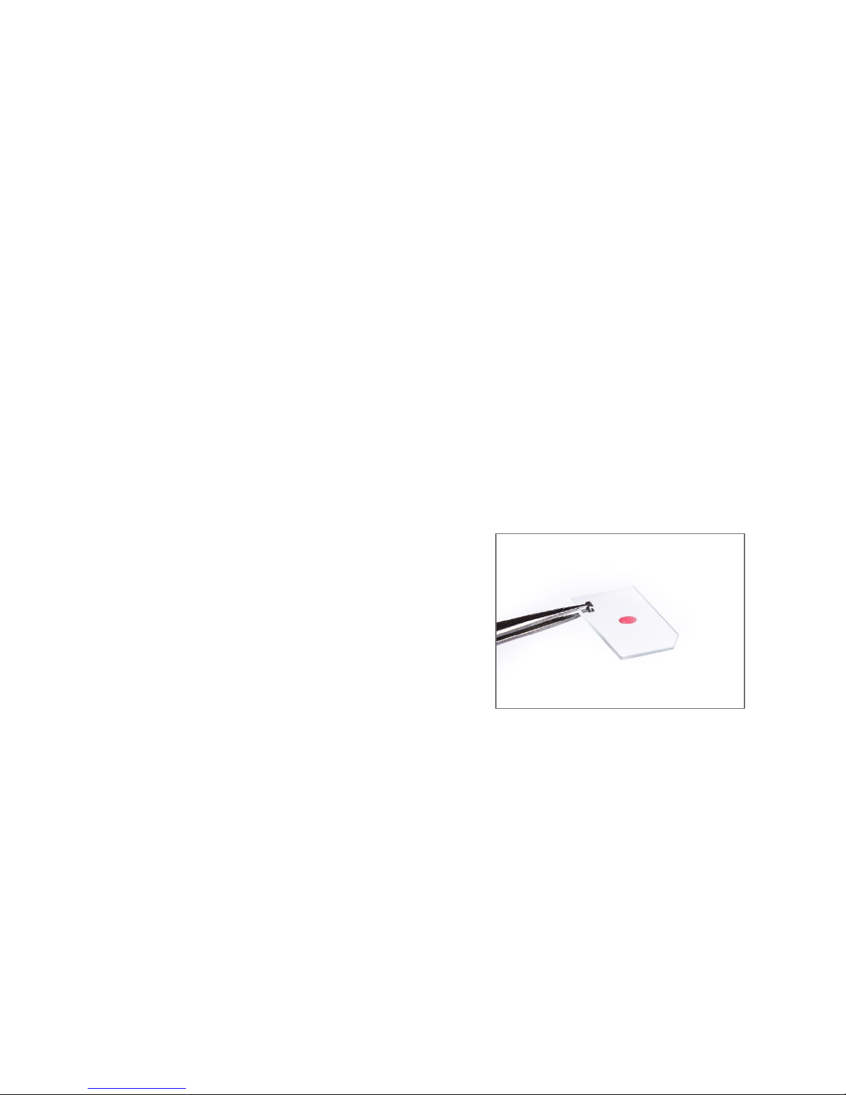
10. Handle Sensor Chips with tweezers and while
wearing gloves [Figure 0.1.1] and other
appropriate personal protection equipment. If
skin contact with the Sensor Chip occurs, rinse
exposed area thoroughly with soap and water.
11. Carefully inspect tubing and connections prior to
testing.
12. It is the responsibility of the user to ensure the
safety and appropriateness of the chemicals,
materials, and fluids being used in the OpenSPR.
13. Treat sensors as hazardous waste after use and follow all local, state/provincial, and
federal regulations. Contact a licensed waste disposal specialist for proper disposal.
14. Do not remove the cover of the OpenSPR. Contact Nicoya Lifesciences Inc. if there is an
issue with the instrument and a customer success scientist will assist you.
15. Do not remove or open the electronics compartment. Contact Nicoya Lifesciences Inc. if
there is an electrical problem and a customer success scientist will assist you.
Figure 0.1.1 - Handle chips with gloves and
tweezers
Page 6

6
OpenSPR 1-Channel Operation Manual V4.1.01
16. Ensure tubing Outlets are fed into an appropriate waste container before turning on the
pump.
17. Turn off the OpenSPR immediately if a leak is detected.
18. Only use blunt-end injection tips in the OpenSPR. Using sharp needle tips will damage the
injection port, and replacement will be at the user’s expense.
This information is based on our present knowledge. However, this does not constitute a
guarantee for any specific product features and shall not establish a legally valid contractual
relationship. Users should make independent decisions regarding completeness of the
information based on all sources available. Nicoya Lifesciences Inc. shall not be held liable for any
damage resulting from handling, contacting, or using this product.
Page 7

7
OpenSPR 1-Channel Operation Manual V4.1.01
1 GETTING STARTED
1.1 Initial Equipment Setup
1.1.1 Before any steps are taken
Prior to setting up your OpenSPR, ensure your laboratory space is setup with the below
requirements:
• A clean and level lab bench with enough space to fit both the OpenSPR and laptop
computer (3.5 ft or 1 m of bench space is recommended)
• 2x power outlets that meet the required power specifications: 100-240V 50-60Hz, 2.25A
max. Surge protected power outlets are recommended.
1.1.2 Standard Equipment Supplies
The OpenSPR Starter Pack will come equipped with the following supplies:
Table 1 OpenSPR Starter Pack supplies.
Quantity
Item
1
OpenSPR instrument
1
OpenSPR power cable
1
USB A-B cable
1
Laptop computer with installed OpenSPR software
1
USB drive containing software set-up files and other relevant documentation
4
250 mL glass bottles (3x containing tubing connector with ferrule, 1x without
tubing connector)
1
Pair of tweezers
1
Hand air pump
1
Pack of Standard Sensors
1
Package of 10 disposable syringes (1 mL)
1
Package of 10 disposable blunt-end injection tips
Page 8
8
OpenSPR 1-Channel Operation Manual V4.1.01
1
Gastight glass syringe (250 µL)
1
Training Kit
1
Declogging Kit
1
Screwdriver (for servicing)
1.1.3 Setting up the OpenSPR
1. Remove the OpenSPR Instrument from the box, and place on a clean, level surface.
2. Remove the Power Cable and USB Cable from the bottle tray of the instrument (right-
hand side) and remove all additional packaging tape present on the instrument.
3. Remove the twist-ties from the tubes within the bottle tray.
4. Unpack the glass bottles from the Accessory Box and remove all tape and stickers from
the lid and fittings.
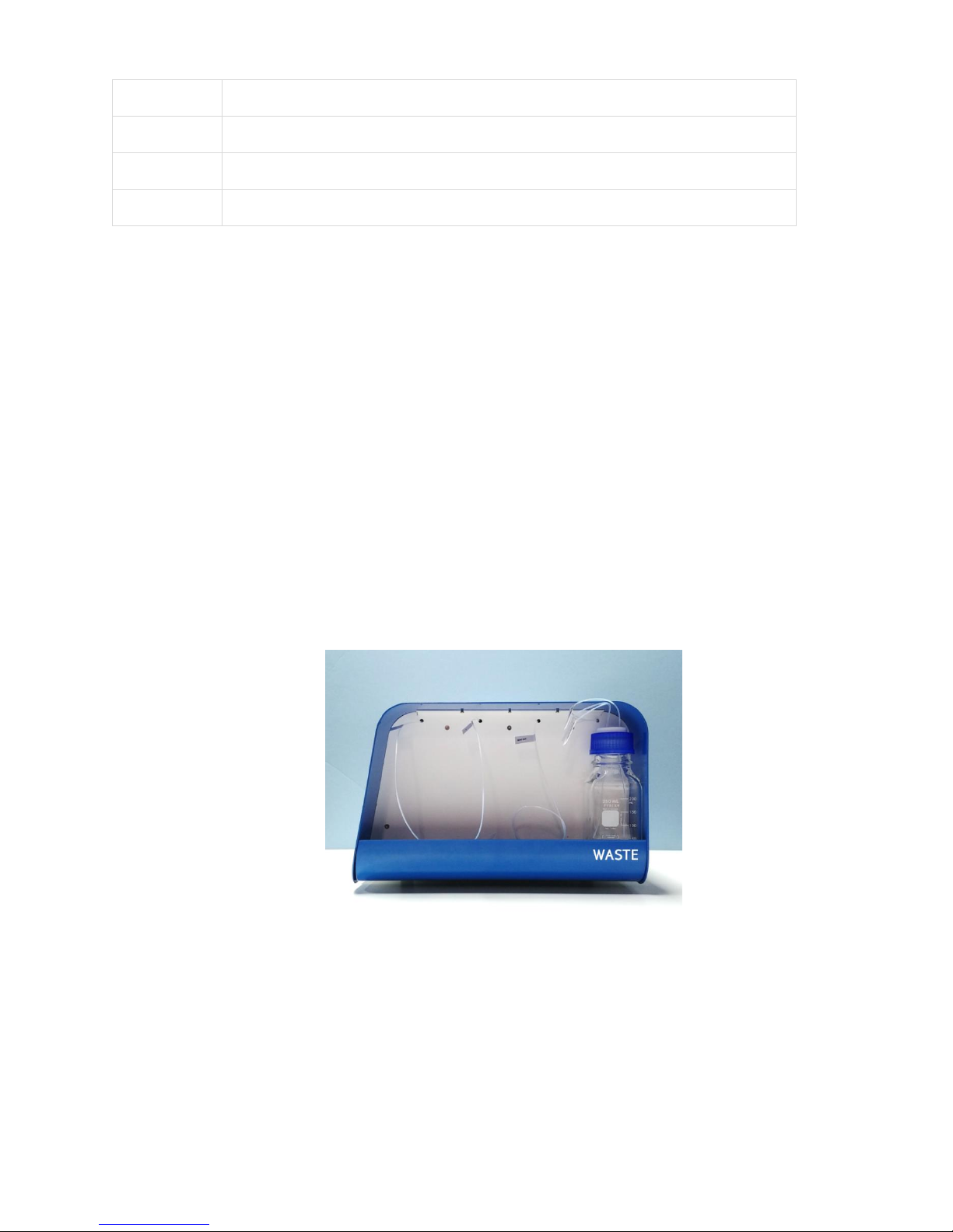
5. Locate the 250 mL glass bottle that does not contain the tube fitting (without the black
attachment on top). This will be your Waste Bottle (tip: it is good practice to label this
bottle accordingly). Find the 3 outlet tubes located in a bundle at the back of the bottle
tray. They will be labelled “Sample Waste”, “Outlet Waste”, and “Pump Waste”. Place all
3 tubes through the openings in the bottle cap, then place bottle at the back of the bottle
tray [Figure 1.1].
Figure 1.1 Waste bottle installed in the OpenSPR with 3 outlet tubes.
6. Locate the 3 remaining 250 mL glass bottles. Fill one of the bottles with 250 mL of filtered
DI water (use a 0.2 µm filter) or MilliQ water, and label accordingly. The remaining 2
bottles will be used for your running buffers (leave these empty until use, but still proceed
with the setup).
Page 9
9
OpenSPR 1-Channel Operation Manual V4.1.01
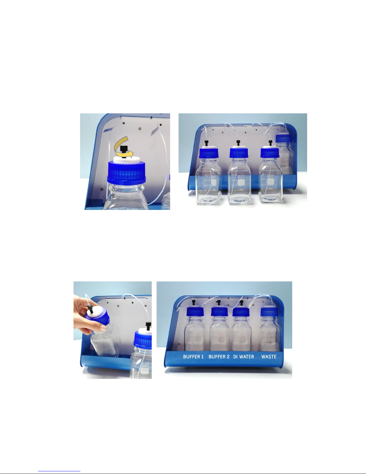
7. The 3 inlet tubes will be inserted into Buffer Bottles 1, 2 and DI Water, respectively, from
front to back of the instrument. The tubes are labelled accordingly. Keep the bottles
outside of the instrument while inserting the tubes.
8. To insert the tubes, loosen the black fitting by turning it counter-clockwise [Figure 1.2-
Left]. Note that there is a translucent ferrule beneath the black fitting. Once the fitting is
loosened, feed the tube through the fitting into the bottle, until the tube touches the
bottom [Figure 1.2 – Right]. When the tube is in the final position, gently tighten the fitting
clockwise until the tube is secured into place (do not over tighten).
Figure 1.2 Left: Loosen the fitting by turning it counter-clockwise before inserting the tube. Right: Inlet tubes properly installed
with the end of the tubes touching the bottom of the bottles.
Note: if buffer bottles 1 and 2 are not going to be used immediately, it is recommended to store
the tubes within the empty bottles to prevent dust from entering the fluidic system.
9. Insert the bottles into the tray by tilting the bottle such that the base of the bottle fits
into the tray first, followed by the top [Figure 1.3].
Figure 1.3 Left: Insert the bottles into the tray base-first and tilted. Right: Proper positioning of all bottles installed in the
OpenSPR.
Page 10
10
OpenSPR 1-Channel Operation Manual V4.1.01
1.1.4 Connecting and Turning on the OpenSPR
If a computer was provided with your instrument, it will have the OpenSPR software
already preinstalled. If a computer was not provided with your instrument, install the
Nicoya Lifesciences software per the directions provided in Section 1.2.
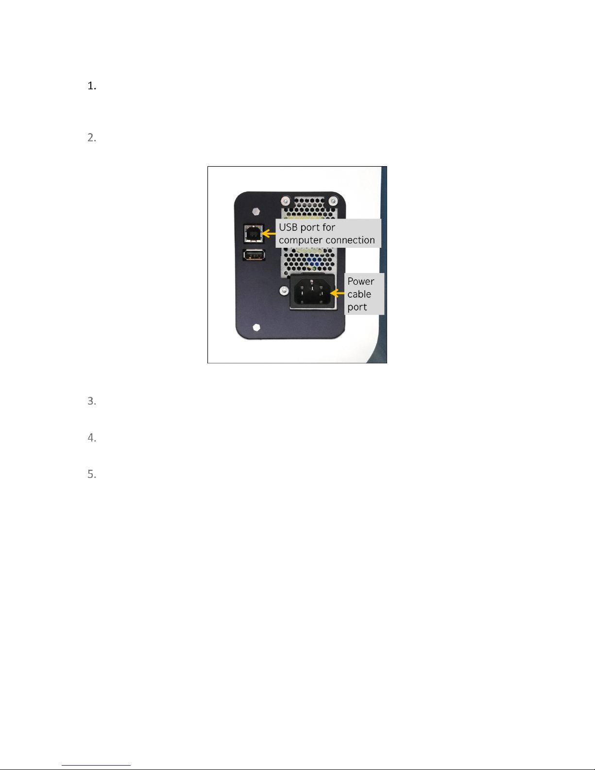
Plug the power cable into the back of the OpenSPR instrument [Figure 1.4] and connect
to the recommended power outlet.
Figure 1.4 USB and power cable ports on the back of the OpenSPR.
Plug one end of the USB Cable into the back of the OpenSPR [Figure 1.4: USB port for
computer connection] and connect the other to the computer.
Power on the OpenSPR using the button located on the front-right panel. Ensure the blue
light around the instrument’s power button turns on.
Prior to using your OpenSPR for the first time after unpacking, contact your Customer
Success Scientist to schedule a remote hands-on training session.
Page 11

11
OpenSPR 1-Channel Operation Manual V4.1.01
1.2 OpenSPR Software Setup
1.2.1 Minimum Computer Requirements
Below are the minimum required computer specifications to be able to run the OpenSPR
software:
Table 2 Minimum required specifications for OpenSPR software.
Operating System
Windows 10, 64-bit
Communication
USB 2.0 or 3.0
Microsoft .NET Framework
4.0
Memory
4 GB RAM
CPU
Dual Core
If you purchased a laptop with your OpenSPR, it will already be setup with the OpenSPR software
and TraceDrawer Analysis Software, you are all set to go! Skip down to Activation of TraceDrawer
Analysis software section.
If you did not purchase a laptop with your OpenSPR, the USB drive in the Accessories Box will
contain the installer for both the OpenSPR and TraceDrawer software.
1.2.2 Installing OpenSPR Software
1. Ensure that the computer meets the specifications listed in Section 1.2.1. It is highly
recommended the computer has access to internet to enable software updates.
2. Perform all Windows software updates before proceeding (this may require a few
computer restarts).
3. Connect the OpenSPR to the computer via the USB cables, and power on the instrument.
4. Transfer the OpenSPR-4.0.XXXX.XXXXX-windows-installer.exe file (from the USB drive or
downloaded from our website) into an accessible folder onto the computer. Double click
this file to run it.
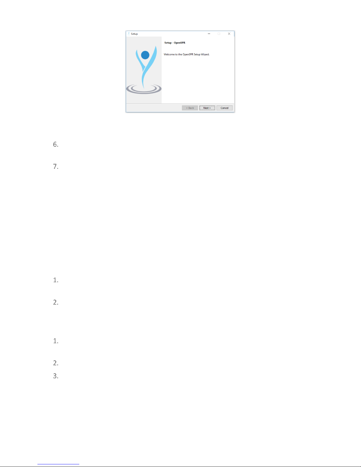
5. The OpenSPR Software Setup Wizard will open [Figure 1.5]. Follow the prompts in this
wizard to complete the installation of the software and drivers. It is recommended to use
the default settings and application file location for installation.
Page 12
12
OpenSPR 1-Channel Operation Manual V4.1.01
Figure 1.5 OpenSPR software setup wizard.
Once the installation wizard finishes, you will find a shortcut to the program called
“OpenSPR” on the desktop.
Restart your computer after the installation is complete.
Important: Ensure that the computer sleep settings are set to never. If the computer falls
asleep during an experiment, the software will lose communication with the instrument, and
the software must be restarted.
1.3 TraceDrawer Software Setup
Setup of the TraceDrawer analysis software is only applicable if a TraceDrawer license key was
purchased.
1.3.1 Installing TraceDrawer
Copy the TraceDrawer_1.8_RidgeviewSetup.exe file from the USB stick onto the
computer.
Run the installer and follow the prompts to complete the installation.
1.3.2 TraceDrawer License Activation
Locate your TraceDrawer License Key. A print-out containing your license key is provided
within the folder of the OpenSPR Accessories box.
Run the TraceDrawer program from the desktop shortcut.
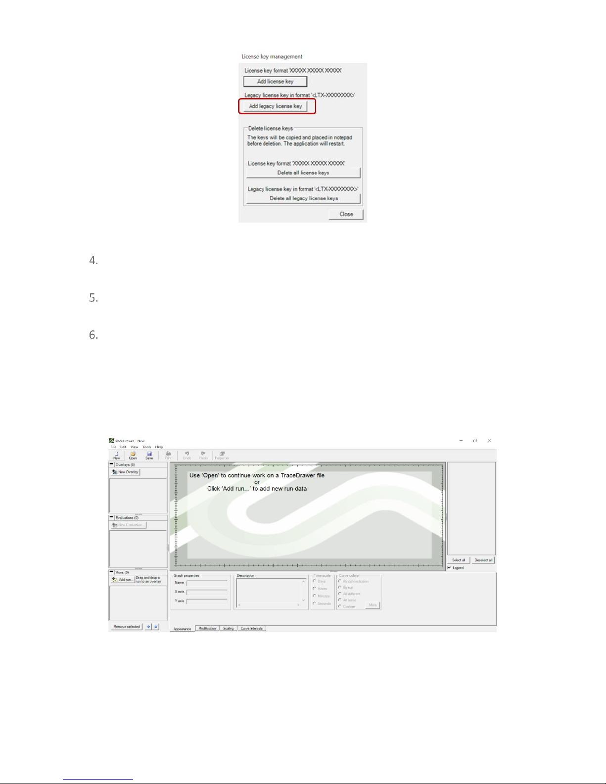
Click “Add Legacy License Key” in the window prompt.
Page 13
13
OpenSPR 1-Channel Operation Manual V4.1.01
Figure 1.6 TraceDrawer license key management window. Select "Load Legacy License Key" only.
Insert your license key with the format <LTV-XXXXXXXX> (note the brackets are apart of
the key and need to be input as well).
Click “Close” in the window prompt. TraceDrawer will restart with your license key
activated.
The TraceDrawer software will now be ready to use and will display the home screen
[Figure 1.7]. For details on how to perform data analysis using TraceDrawer, please refer
to the TraceDrawer Data Analysis Handbook.
Tip: It is recommended to create a local file on your computer containing this license key. When
Windows Updates occur, you may be prompted to re-enter the TraceDrawer license key.
Figure 1.7 TraceDrawer home screen once activated with license key.
Page 14

14
OpenSPR 1-Channel Operation Manual V4.1.01
2 STANDARD OPERATING PROCEDURES
2.1 Preparation for your Experiment
2.1.1 Required Items
The following materials are required to run a test on the OpenSPR:
• OpenSPR instrument with corresponding power and USB cables
• Computer with installed OpenSPR software
• 4x 250 mL glass buffer bottles (or equivalent)
• Tweezers
• Lint-fee wipes
• Syringes with blunt-end tips installed
• Blank Chip
• OpenSPR Sensor Chip *see optical setup considerations in section below
• Deionized (DI) water, filtered (0.2 µm filter)
• Running buffer, filtered (0.2 µm filter) and degassed
• Solution of 80% isopropanol (v/v in water)
• Relevant Personal Protective Equipment
2.1.2 Fluidic Setup
Prior to starting your experiment, the fluidic setup must be in place for proper function of the
OpenSPR. This includes having the Waste Bottle, DI Water Bottle, and Buffer Bottles filled to the
proper levels with tubes installed correctly. Details for each bottle and tubing setup are provided
below.
Waste Bottle: 250 mL square glass bottle (or equivalent) that does not contain the tube fitting.
• Ensure the Waste Bottle is empty and labelled appropriately as waste.
• Secure the cap onto the bottle.
• Insert all 3 outlet tubes into the holes located on the top of the waste bottle. The outlet
tubes are the bundle of 3 protruding from the very back of the bottle tray.
• Place the Waste Bottle containing the 3 outlet tubes at the back of the Bottle tray, as
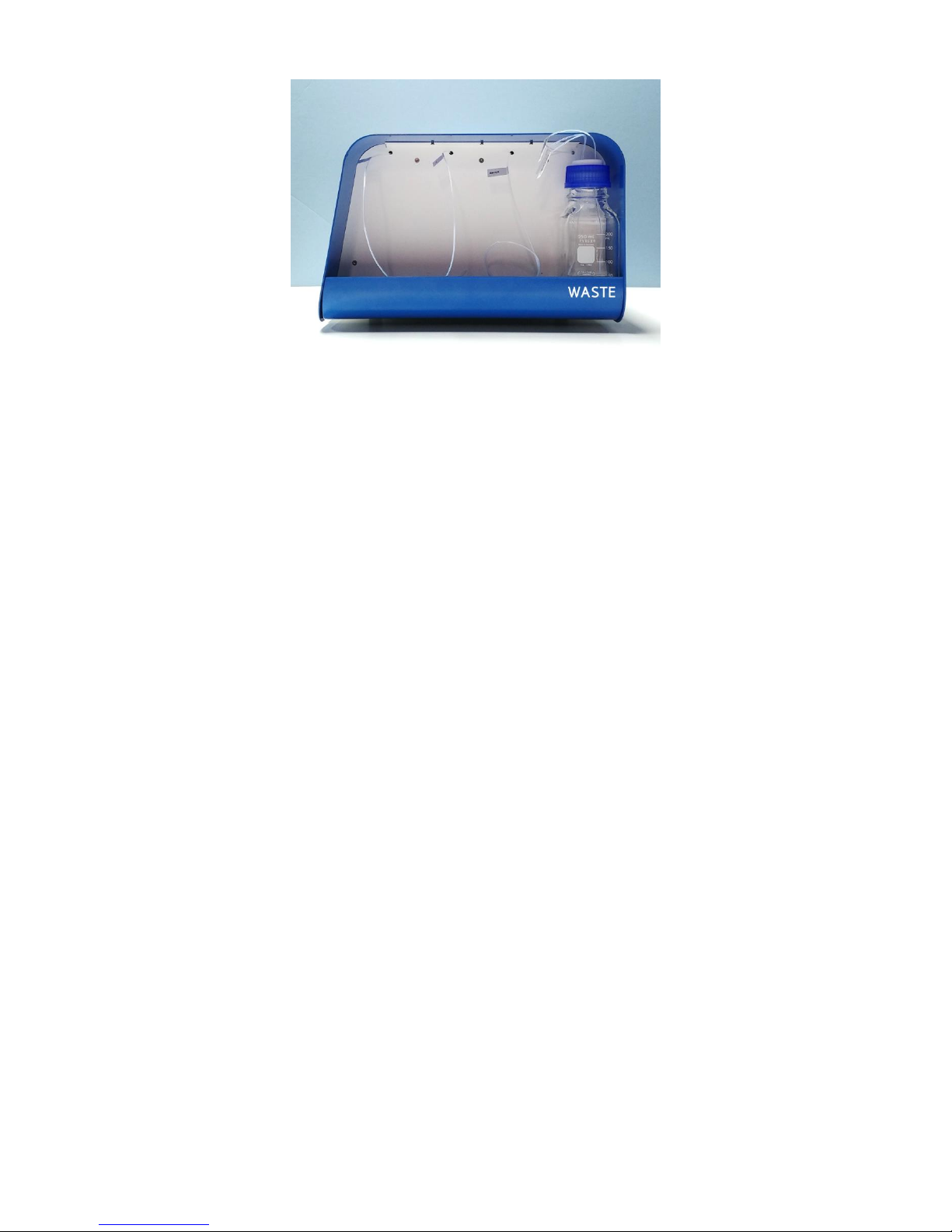
shown in [Figure 2.1].
Page 15
15
OpenSPR 1-Channel Operation Manual V4.1.01
Figure 2.1 Empty waste bottle installed in the OpenSPR containing 3 outlet tubes.
DI Water Bottle: 250 mL square glass bottle containing a tube fitting
• Fill this bottle with 250 mL of filtered (0.2 µm filter) deionized water.
• Secure the cap onto the bottle.
• Loosen the fitting, and place the 3rd inlet tube into the bottle, such that the tube is just
touching the bottom of the bottle.
• Gently tighten the fitting on the tube such that it is secured into place.
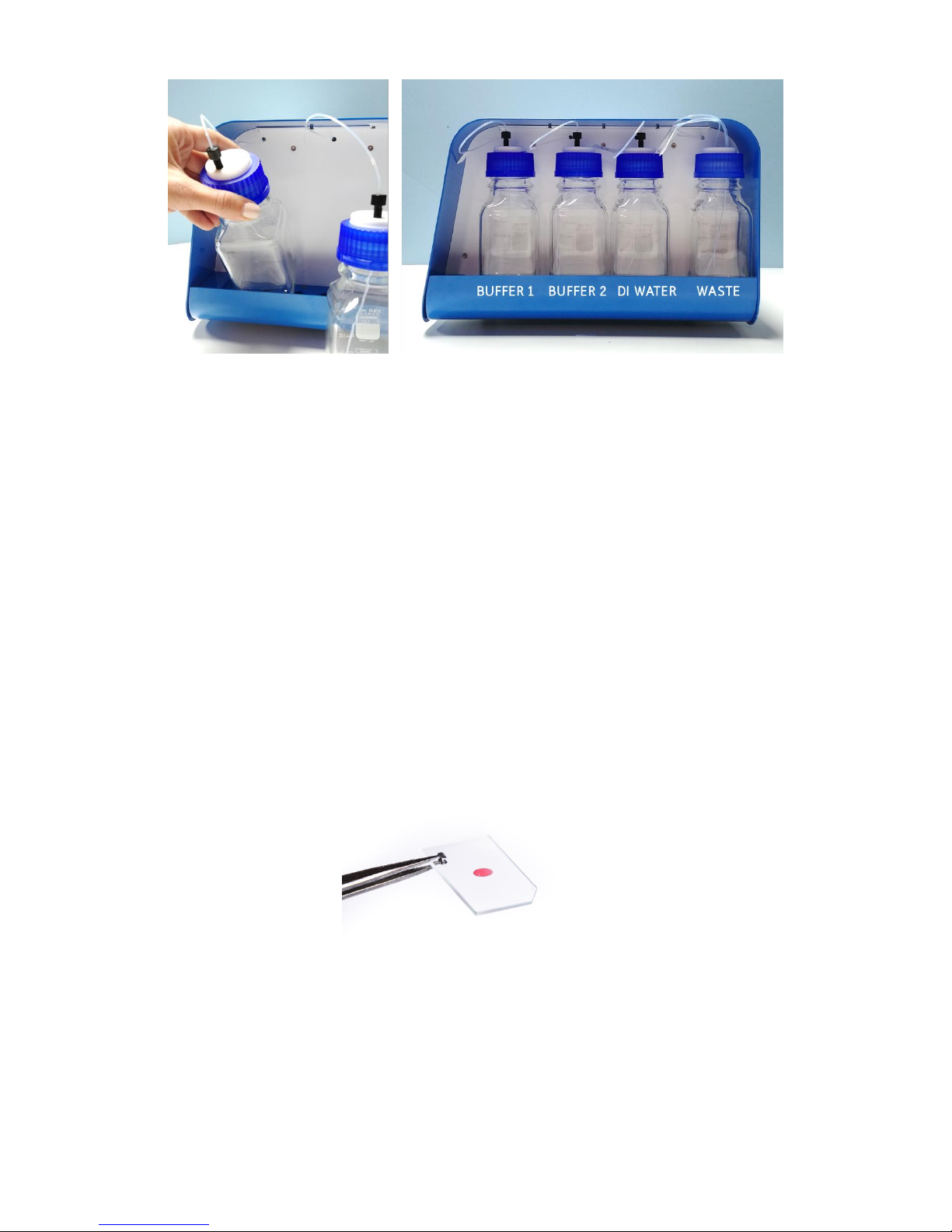
• Place the bottle onto the tray of the OpenSPR next to the Waste Bottle [Figure 2.2].
Buffer Bottle 1 and 2: 250 mL square glass bottles containing a tube fitting
• Prepare at least 100-250 mL of each running buffer for your experiment*
• Filter (using a 0.2 µm filter) and degass the running buffers prior to use.
• Fill the appropriate bottles with the running buffer to a maximum level of 250 mL.
• Secure the cap onto the bottle.
• Loosen the fitting and place the 1st and or 2nd inlet tube into appropriate buffer bottle,
such that the tube is just touching the bottom of the bottle.
• Gently tighten the fitting on the tube such that it is secured into place.
• Place the bottles onto the tray of the OpenSPR [Figure 2.2].
Page 16
16
OpenSPR 1-Channel Operation Manual V4.1.01
Figure 2.2 Left: Insert the bottles into the tray base-first and tilted. Right: Proper positioning of all bottles installed in the
OpenSPR.
*Notes:
• For most experiments, only one running buffer may be required. If this is the case, it is
recommended to prepare the buffer in the Bottle 1 Position. The inlet tube for Bottle 2
may be left in an empty bottle to prevent dust accumulation.
• It is recommended to keep at least 50 mL of each running buffer in a separate container
to use to rinse the injection port during your experiment.
2.1.3 Optical Setup
The 1-Channel OpenSPR comes pre-installed with a Cool Light LED for analysis using any standard
OpenSPR Sensor Chips (red sensor spot) [Figure 2.3]. The 1-Channel OpenSPR is not compatible
with Nicoya’s High Sensitivity Sensors as a different optical setup is required. For use of the High
Sensitivity Sensors upgrade packages are available – please contact a Customer Success scientist
for more details.
Figure 2.3 OpenSPR Standard Sensor.
Page 17
17
OpenSPR 1-Channel Operation Manual V4.1.01
2.2 Beginning a Test
Prior to beginning a test for the first time after receiving and unpacking your OpenSPR Instrument,
ensure you complete a hands-on training with a Customer Success Scientist at Nicoya Lifesciences.
Verify the fluidic setup is complete (Section 2.1.2).
Ensure the USB is connected to both the OpenSPR and computer running the OpenSPR
software, and that the instrument is connected to an appropriate power source.
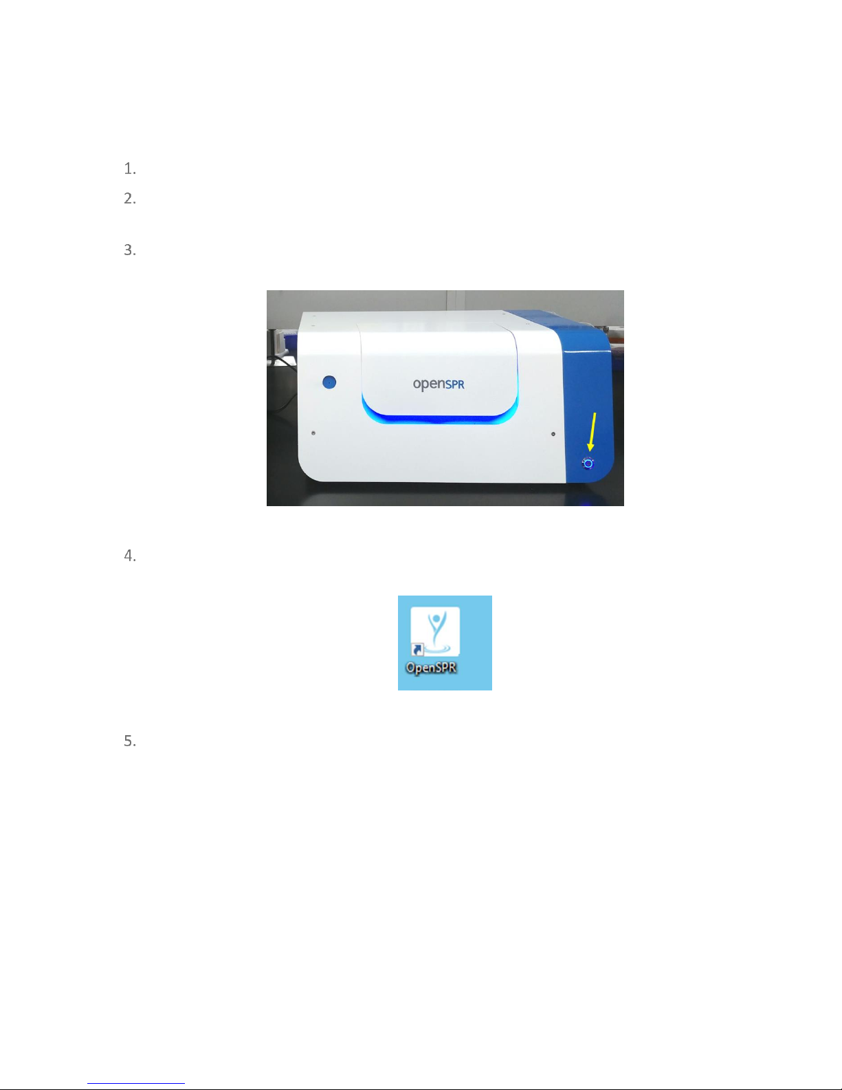
Power on the OpenSPR using the Power Button on the front of the instrument [Figure
2.4]. The blue lights of the OpenSPR should turn on, and the instrument will initialize.
Figure 2.4 Location of power button on the OpenSPR.
Run the OpenSPR software program by double-clicking on the desktop icon named
“OpenSPR” [Figure 2.5].
Figure 2.5 OpenSPR software desktop shortcut.
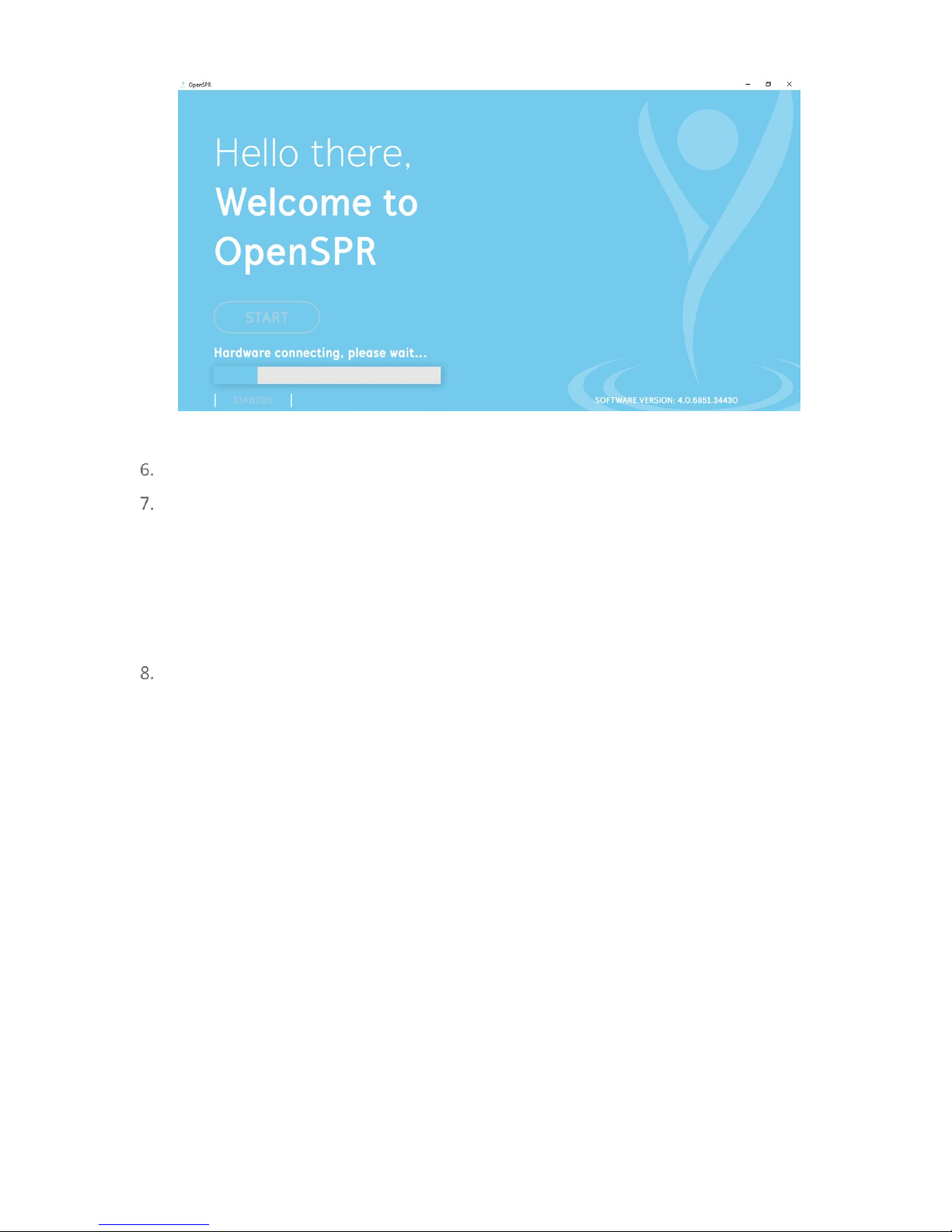
Upon opening the software, the communication connection to the OpenSPR instrument
will attempt to be established. It may take several seconds for the connection to
complete. During this time, the progress bar will be active [Figure 2.6]. Do not disconnect
or power off the OpenSPR during this time.
Page 18
18
OpenSPR 1-Channel Operation Manual V4.1.01
Figure 2.6 OpenSPR home screen with hardware connection in progress.
Once the connection is complete the Start button will be active.
If the communication connection is not able to be established, an error message will
appear in red. If this happens, unplug the USB connection to the computer, power cycle
the OpenSPR, then re-establish the USB connection. If the software is still unable to
connect, restart the software.
Tip: to power off the OpenSPR, hold the power button down for 10 seconds until the power LED
turns off
Click “Start” to enter the software. The software will walk you through the Instrument
Setup, and Sensor Setup procedures prior to collecting your data – see sections below for
details.
2.3 Instrument Setup
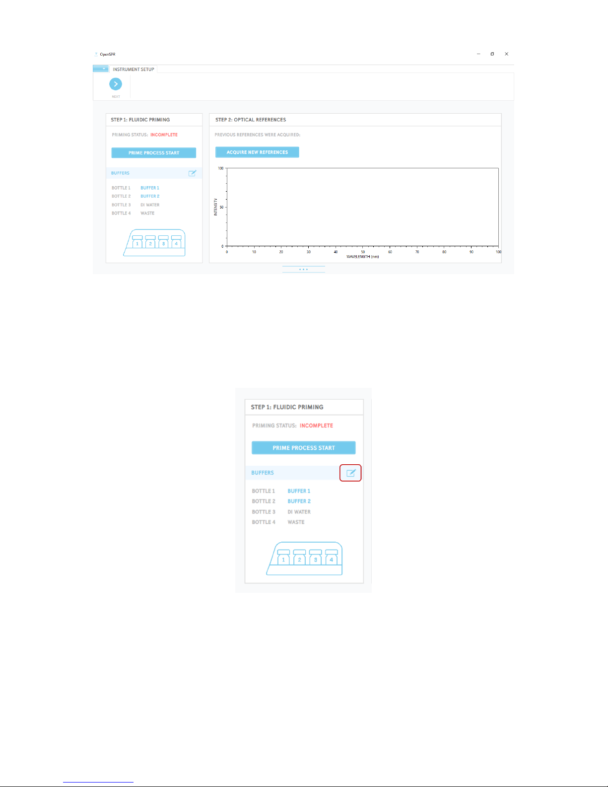
When entering the OpenSPR Software, you will begin on the Instrument Setup Screen [Figure
2.7]. This screen will allow you to indicate your running buffers used for your test, prime the
fluidics of the OpenSPR, as well as setup optical references. Full details for each of these
procedures are provided in the sections below.
Page 19
19
OpenSPR 1-Channel Operation Manual V4.1.01
Figure 2.7 Instrument setup screen.
2.3.1 Naming your Running Buffers
It is convenient to log the different types of running buffers to be used in your test. You can do
so by selecting the “edit” icon next to the Running Buffer title in the Fluidic Priming section [Figure
2.8].
Figure 2.8 Edit button located in the Fluidic Priming section. This allows the user to input the different buffer solutions used in
the test.
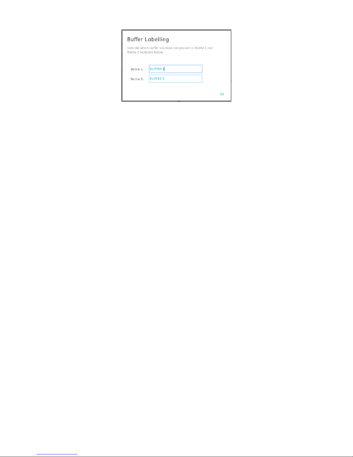
Clicking this icon will open a new window which will allow you to input the names of the running
buffers in both Bottle 1 and Bottle 2 [Figure 2.9]. You will also be given the option to input the
names of the running buffer during the Priming process as well (Section 2.3.2). Note that the DI
Water and Waste bottle designations cannot be changed.
Page 20
20
OpenSPR 1-Channel Operation Manual V4.1.01
Figure 2.9 Option to label your running buffers.
The completion of this step is not required for running a test but is recommended for your
experimental records.
2.3.2 Step 1: Fluidic Priming
Priming of the OpenSPR will fill the pumps and tubing with the running buffer to be used for the
test.
It is necessary to perform priming in the below scenarios:
1) Initial use of the instrument from purchase
2) If the instrument is being used for the first time after a full shutdown
3) If you would like to use a new running buffer for your test
4) If you are going to be starting with a running buffer in an alternate bottle position
If you are running a test with the running buffer already present in the system, using the same
bottle position and if no air has been introduced into the inlet tubing, then you do not need to
perform the priming procedure. In this scenario, you can leave the fluidic priming as incomplete
to move forwards with your test setup.
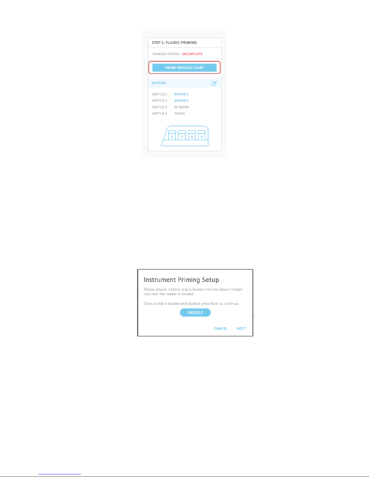
To prime the instrument with a new running buffer, click the “Prime Process Start” button [Figure
2.10] and follow the on-screen prompts.
Page 21
21
OpenSPR 1-Channel Operation Manual V4.1.01
Figure 2.10 Prime Process Start button.
The prompts will guide you though setting up the hardware to perform the priming procedures,
detailed below:
1. To setup the instrument for priming, ensure that a chip (either a blank chip or a sensor
chip) is installed in the sensor holder and docked in the system. The OpenSPR will come
pre-installed with a blank chip for your convenience upon receiving. In the prompt, you
will be able to undock the sensor stage in order to insert or change a chip if necessary
[Figure 2.11]. Instructions for placing a chip into the system can be found in Section 2.4.1.
Do not install the sensor to be used for your experiment at this stage to perform the
priming. When a chip is docked in the system, select “Next” to proceed.
Figure 2.11 Setup the instrument for priming by having a chip installed in the system.
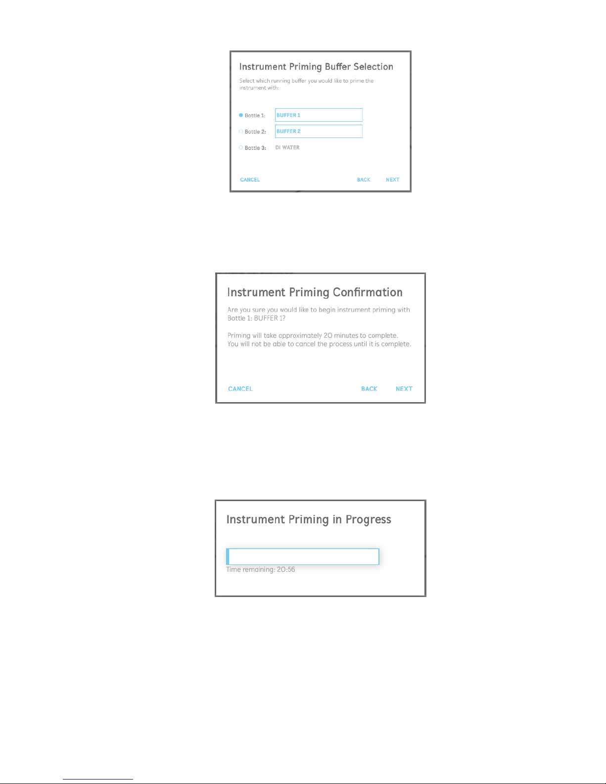
2. Select which running buffer and bottle you would like to use for priming using the radio
buttons next to the bottle names [Figure 2.12]. The user will have the option to select the
buffer in bottle 1, bottle 2, or to use DI water (for cleaning/rinsing procedures). The user
can also input the names of the running buffers located in the bottles at this stage. Once
your desired bottle has been selected, click “Next” to proceed.
Page 22
22
OpenSPR 1-Channel Operation Manual V4.1.01
Figure 2.12 Instrument priming buffer selection and naming.
3. The user will be directed to a window confirming that they would like to proceed with the
priming with the selected running buffer [Figure 2.13]. Instrument priming will take
approximately 21 minutes to complete. To begin the priming, select “Next”.
Figure 2.13 Confirmation to begin instrument priming.
4. A window with a progress bar will appear indicating how much time is remaining in the
process [Figure 2.14]. During the priming process, it is recommended to rinse the injection
port with at least 3 mL of the running buffer used for priming (taken from the separate
buffer bottle set aside for this purpose).
Figure 2.14 Instrument priming progress bar.
5. When the priming process is complete, the priming status in the software will be updated
accordingly.
Page 23
23
OpenSPR 1-Channel Operation Manual V4.1.01
2.3.3 Step 2: Optical References
Optical references are important to be able to measure the absorbance of the nanogold sensor
chip to receive an accurate response signal. Once references are obtained for the OpenSPR unit,
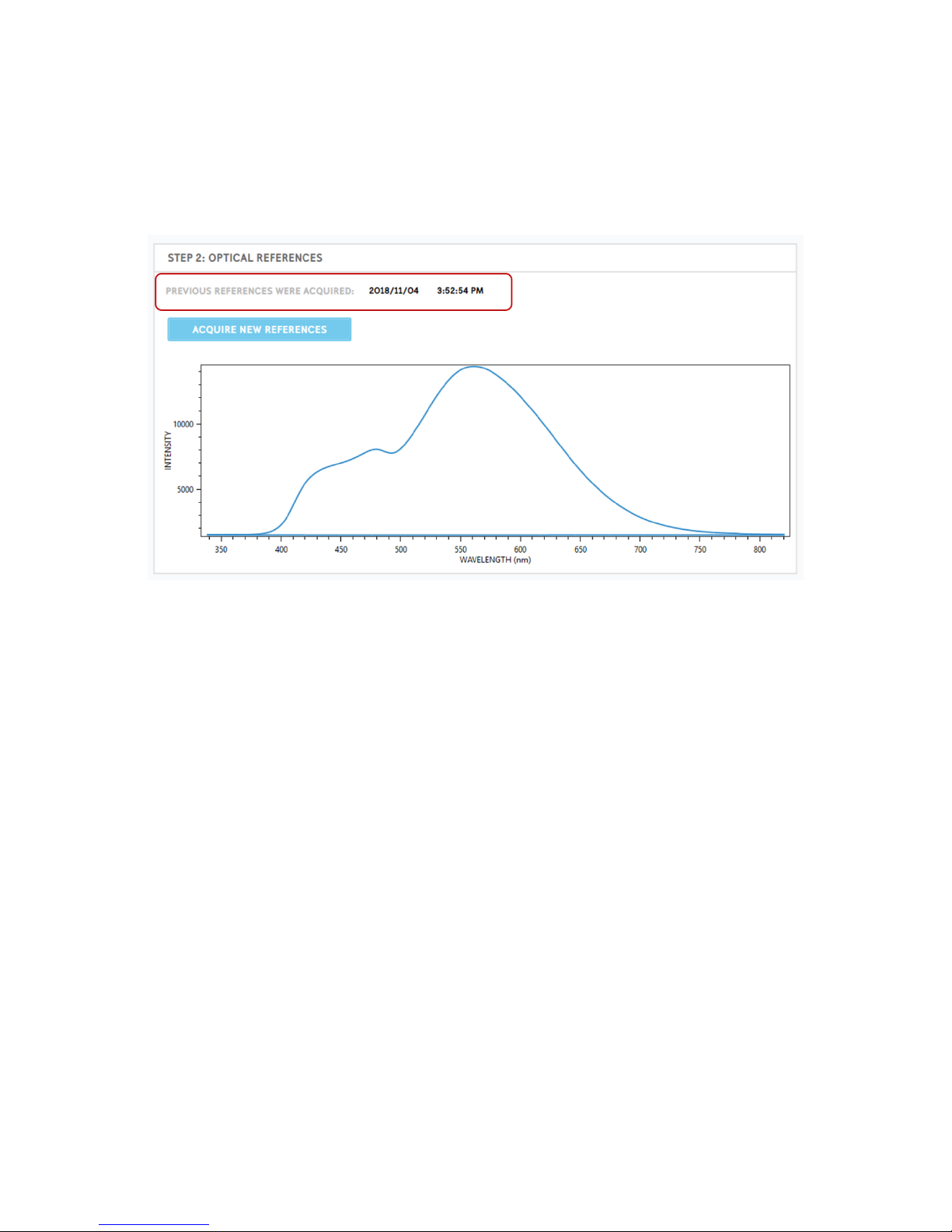
they will be valid for multiple tests. The date and time when the previous references were
acquired will be displayed on the main screen [Figure 2.15].
Figure 2.15 Date and time previous references were acquired as well as expected reference for 1-Channel OpenSPR.
It is only recommended to take new references in the below scenarios:
1) The previous references were acquired more than 1 month ago
2) An insufficient absorbance signal is obtained with a new sensor
Optical references will normalize the optics with respect to the ambient lighting in the room (dark
reference) and the LED light source in the OpenSPR (bright reference). After reference are
acquired, the reference graph should look similar to that shown in the figure above [Figure 2.15].
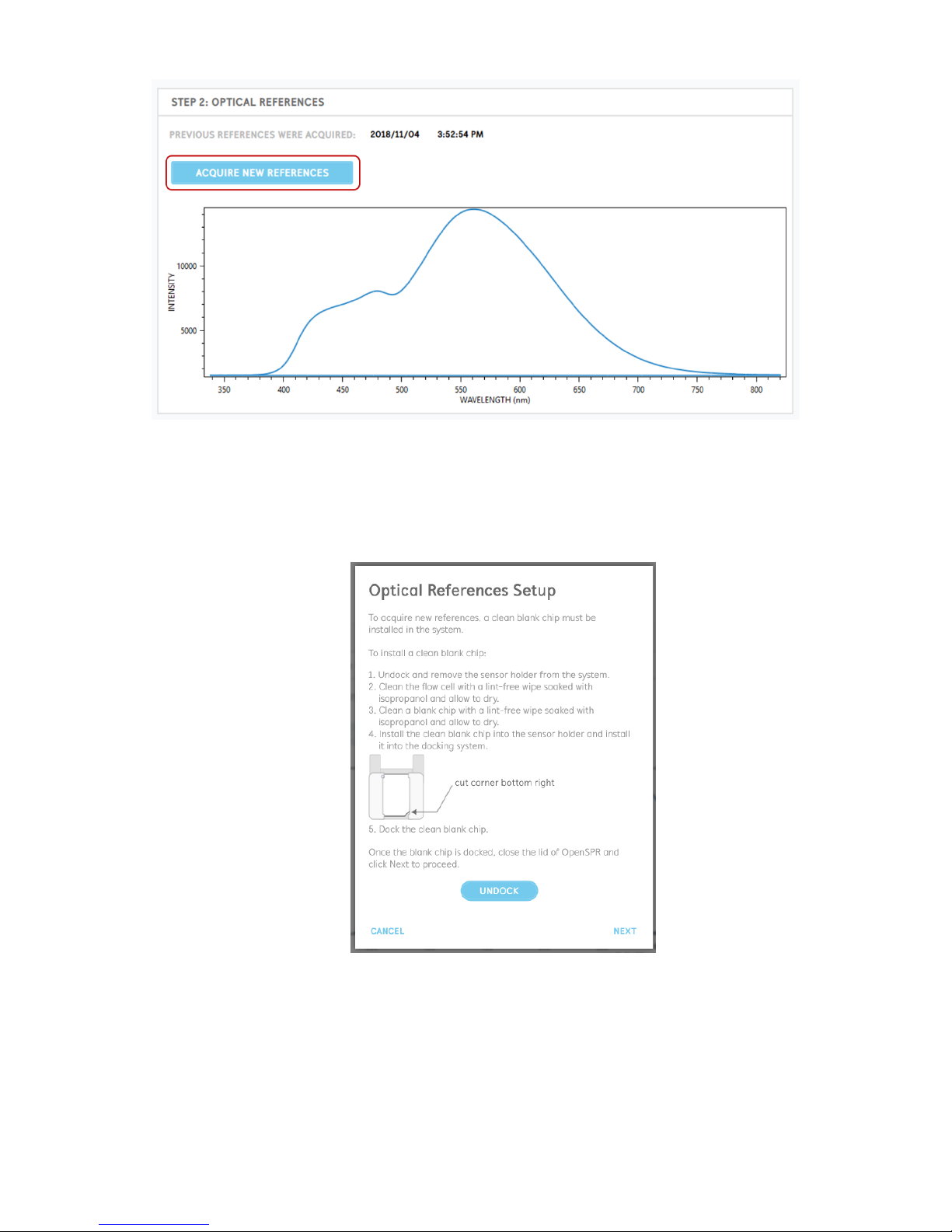
To begin the process to take new references, click the “Acquire New References” button [Figure
2.16] and follow the on-screen prompts.
Page 24
24
OpenSPR 1-Channel Operation Manual V4.1.01
Figure 2.16 Acquire new references process start button.
The process for taking new optical references is detailed below:
1. To be able to take the references, a clean blank chip must be installed in the OpenSPR
[Figure 2.17]. To install a blank chip into the OpenSPR, follow the directions below.
Figure 2.17 Optical reference setup instructions.
2. First, with the lid of the OpenSPR closed, undock the sensor stage using the button located
in the instruction window. When the stage is undocked, remove the sensor holder from
the system.
Page 25
25
OpenSPR 1-Channel Operation Manual V4.1.01
3. Clean the flow cell with a lint-free wipe soaked in isopropanol (80% isopropanol will work
for this purpose as well). Ensure the channels of the flow cell are clear of any large dust
or debris. Allow the flow cell to air dry.
4. Clean a blank chip with a lint-free wipe soaked in DI water followed by isopropanol.
Inspect the chip such that no fingerprints or residue is present in the center near the
optical path.
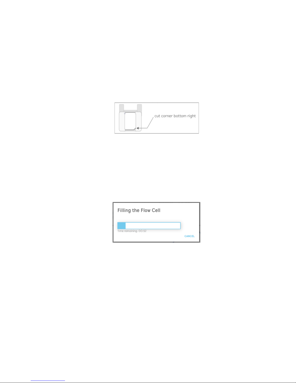
5. Install the blank chip into the sensor holder with the cut corner located in the bottom
right [Figure 2.18]. The entire window of the holder should be covered by the chip with
proper installation.
Figure 2.18 Proper installation of blank chip into the sensor holder.
6. Install the holder containing the blank chip into the sensor stage, close the lid of the
OpenSPR, then dock the stage using the button available in the window.
7. Once the blank chip is fully installed into the OpenSPR, select “Next” in the window [Figure
2.17] to proceed.
8. The flow cell will now begin to fill with running buffer. This process will take approximately
2 minutes to complete – a progress bar will display the time remaining [Figure 2.19].
Figure 2.19 Progress bar filling flow cell with buffer for references.
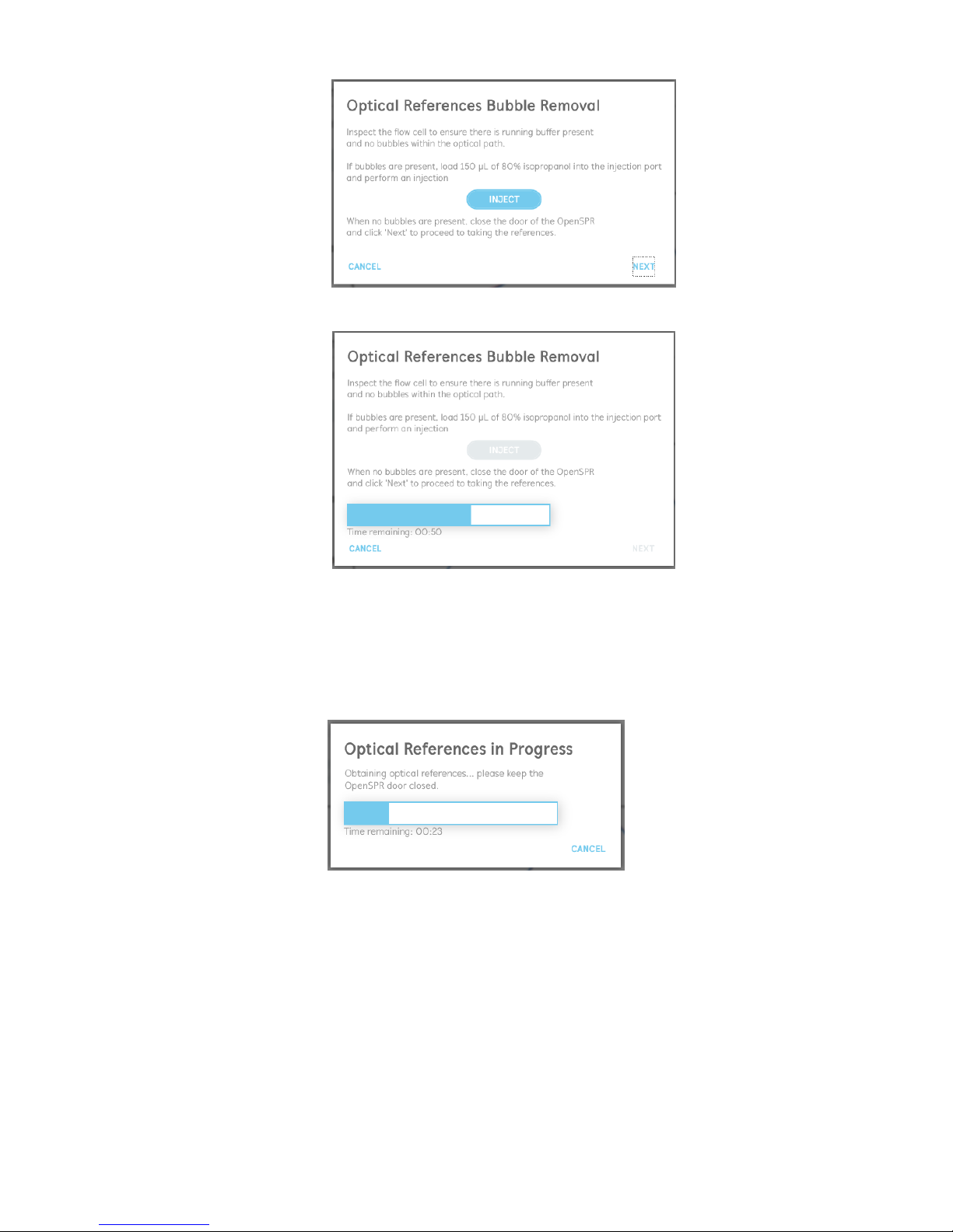
9. Once the flow cell filling is complete, the user is asked to inspect the channels within the
optical path for the presence of bubbles [Figure 2.20]. The optical path must be clear of
bubbles to obtain proper references.
If bubbles are present, load at least 150 µL of 80% isopropanol into the injection port and
click inject to clear the bubbles. The injection progress will be displayed in the window
[Figure 2.21]. Repeat this process until all bubbles have been removed.
Page 26
26
OpenSPR 1-Channel Operation Manual V4.1.01
Figure 2.20 Optical references bubble inspection and removal.
Figure 2.21 Optical references bubble removal in progress.
10. When the optical path is cleared of all bubbles, close the lid of the OpenSPR and select
“Next” to begin taking the optical references. The process will take approximately 2
minutes to complete and the progress will be displayed [Figure 2.22]. Keep the lid of the
OpenSPR closed during this process.
Figure 2.22 Optical references progress display.
11. Once the optical references are complete, the date and time the last references were
taken will be updated accordingly on the main screen. It is recommended to inspect the
references to ensure they look accurate [Figure 2.15].
Page 27
27
OpenSPR 1-Channel Operation Manual V4.1.01
2.4 Sensor Setup
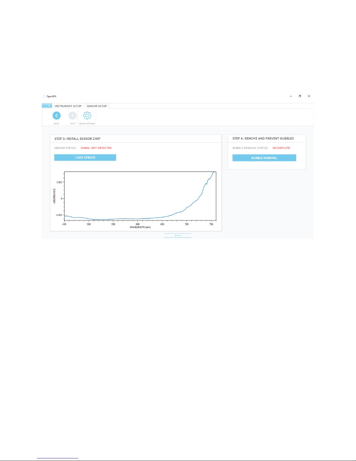
Once the priming and reference processes are complete (if needed), click “Next” in the navigator
located in the upper left of the menu bar. This will bring you to the Sensor Setup screen* [Figure
2.23]. This screen will bring you through the processes of loading a new sensor and removal and
prevention of bubbles within the fluidic path. Full details for each of these procedures are
provided in the sections below.
Figure 2.23 Sensor Setup screen.
* Note that the status of each of the processes shown and the plots of the absorbance graphs
will be different depending on the instrument state.
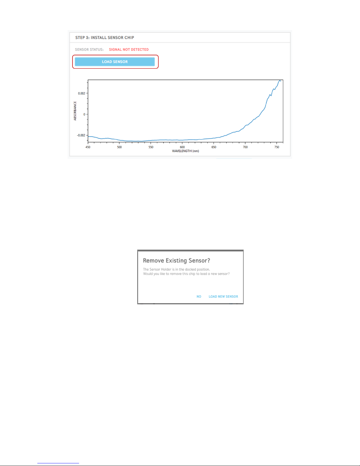
2.4.1 Step 3: Install Sensor Chip
To install a new sensor for your test, click the “Load Sensor” button [Figure 2.24].
Page 28
28
OpenSPR 1-Channel Operation Manual V4.1.01
Figure 2.24 Load Sensor button to begin the process to install a new sensor.
A series of prompts will provide directions on how to prepare the sensor and install it into the
OpenSPR for analysis. Details for this process are provided in the steps below:
1. If the sensor holder is in the docked position, the software will first ask if you would like
to continue with the current sensor installed or if you would like to load a new one [Figure
2.25]. To place a new sensor into the instrument, ensure the lid of the OpenSPR is closed
and select “Load New Sensor”. At this time the sensor stage will automatically undock for
you.
Figure 2.25 Prompt asking if you would like to remove existing sensor.
2. A prompt will appear instructing you to remove the existing sensor or chip from the
system [Figure 2.26].
Page 29
29
OpenSPR 1-Channel Operation Manual V4.1.01
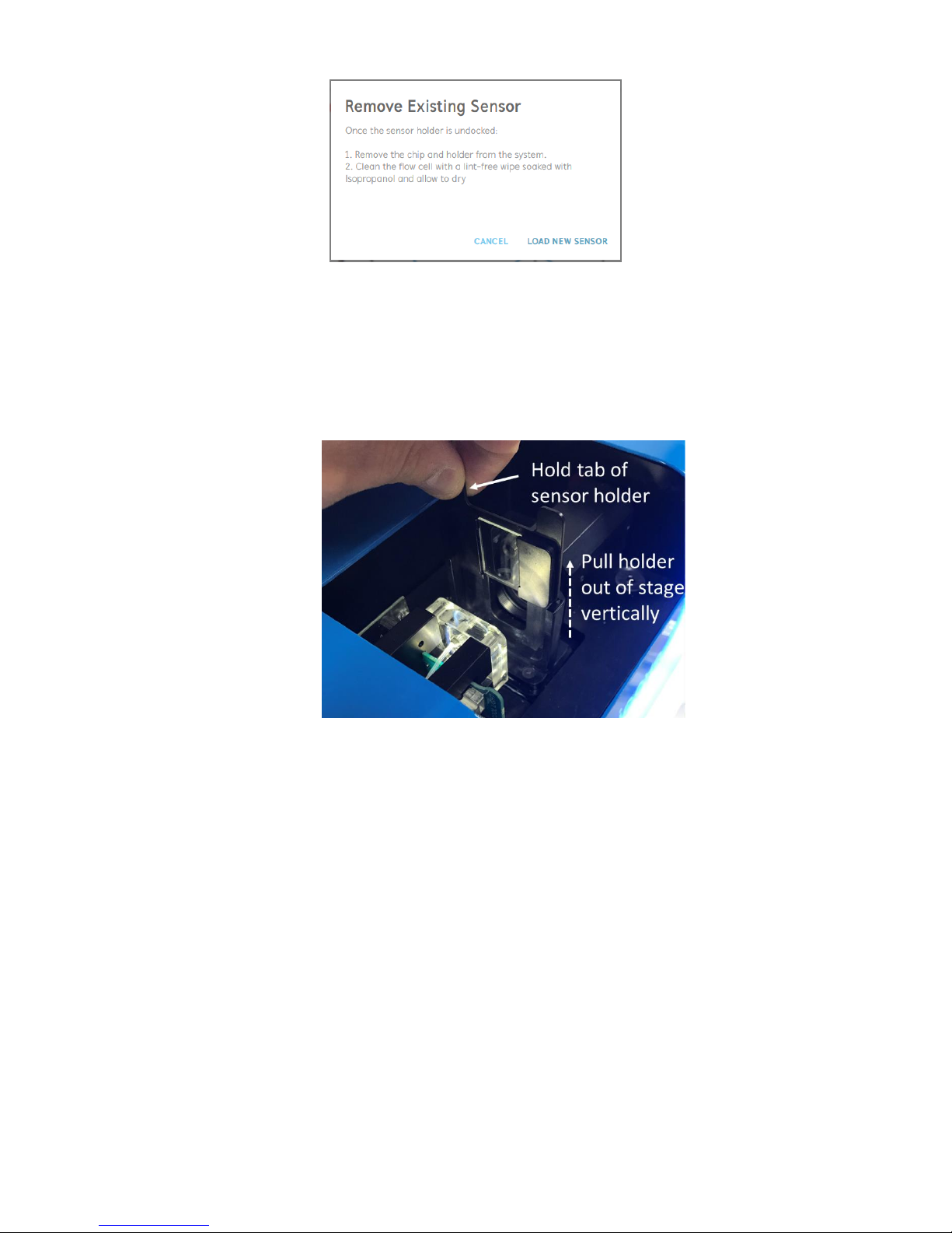
Figure 2.26 Prompt instructing user to remove existing sensor or chip from the system.
3. Once the stage is fully undocked and stationary, open the lid of the OpenSPR and remove
the sensor holder containing the existing chip from the system. To do this, lift the tabs of
the sensor holder straight out of the stage [Figure 2.27]. The existing chip can be removed
from the holder at this time, and the holder can be set aside to be used in subsequent
steps.
Figure 2.27 Remove the sensor holder from the stage by lifting vertically from the tabs.
4. Clean the face of the flow cell by gently wiping it with a lint-free wipe dampened with
isopropanol (diluted isopropanol will work for this purpose as well). After cleaning the
flow cell allow it to air dry.
The purpose of this step is 3-fold: 1) It will wick away any residual buffer, 2) It will remove
any dust present in the fluidic channels, and 3) Clean and sterilize the fluidic channels.
Perform a visual inspection of the microfluidic channels for the presence of dust. If any
dust is present within the channels, repeat the cleaning procedure until they are dustfree.
When the flow cell is clean and fully dry, click “load new sensor” to proceed to the next
step [Figure 2.26].
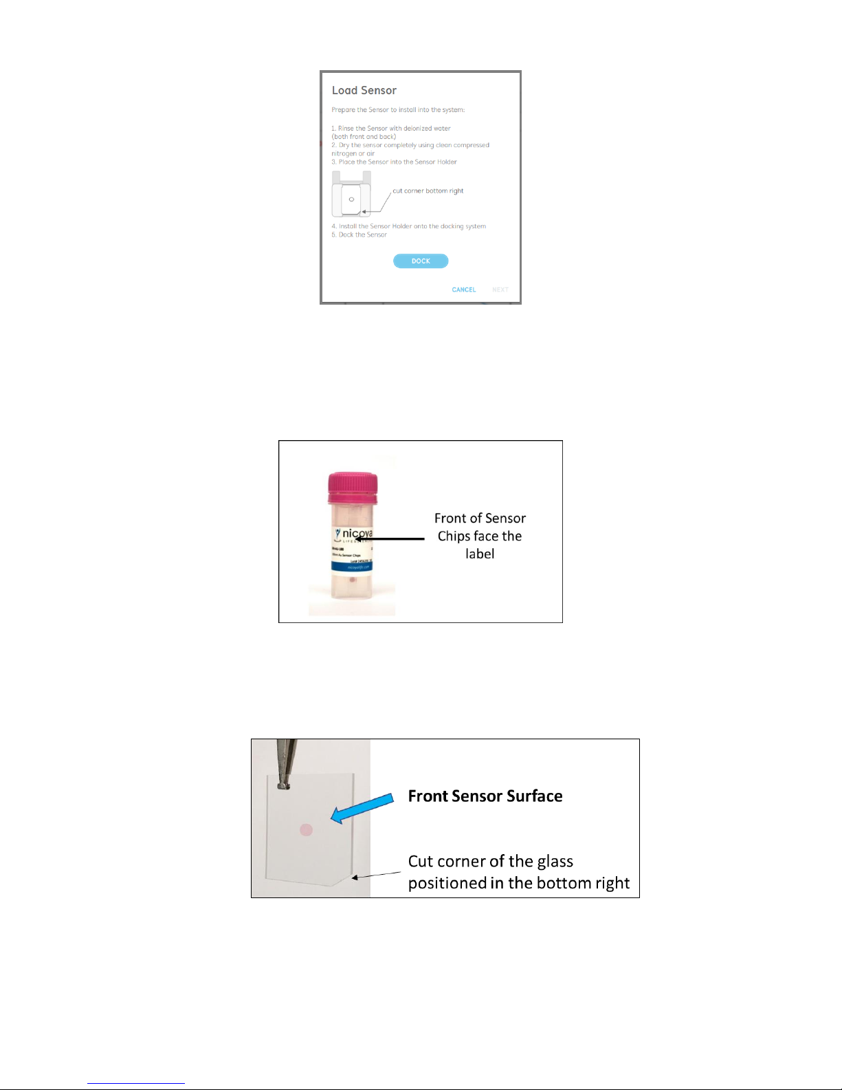
5. The new prompt will guide you through the process to load your new sensor [Figure 2.28]
and is detailed the following steps.
Page 30
30
OpenSPR 1-Channel Operation Manual V4.1.01
Figure 2.28 Prompt instructing user to load the new sensor.
6. Using a pair of tweezers, remove a sensor chip from the storage container. All sensor chips
are packaged with the front sensor surface facing the label on the outside of the storage
container [Figure 2.29]. Do not touch the sensor spot directly, as this will scratch the
surface and severely diminish its performance.
Figure 2.29 Front of the sensor chips face the label stored in the container.
The front sensor surface can also be identified using the cut corner of the sensor chip.
When viewing the sensor in a vertical position, when the cut corner can be positioned in
the bottom right, as shown in Figure 2.30, you will be viewing the front sensor surface.
Figure 2.30 With the sensor chip in the vertical position, when the cut corner is in the bottom right, you are viewing the front
sensor surface.
Page 31
31
OpenSPR 1-Channel Operation Manual V4.1.01
7. The sensor chip should be rinsed with distilled/deionized water, then dried with clean
compressed air or nitrogen (both the front and back of the chip). It is important that the
sensor chip be completely dry for it to make a proper seal with the flow cell.
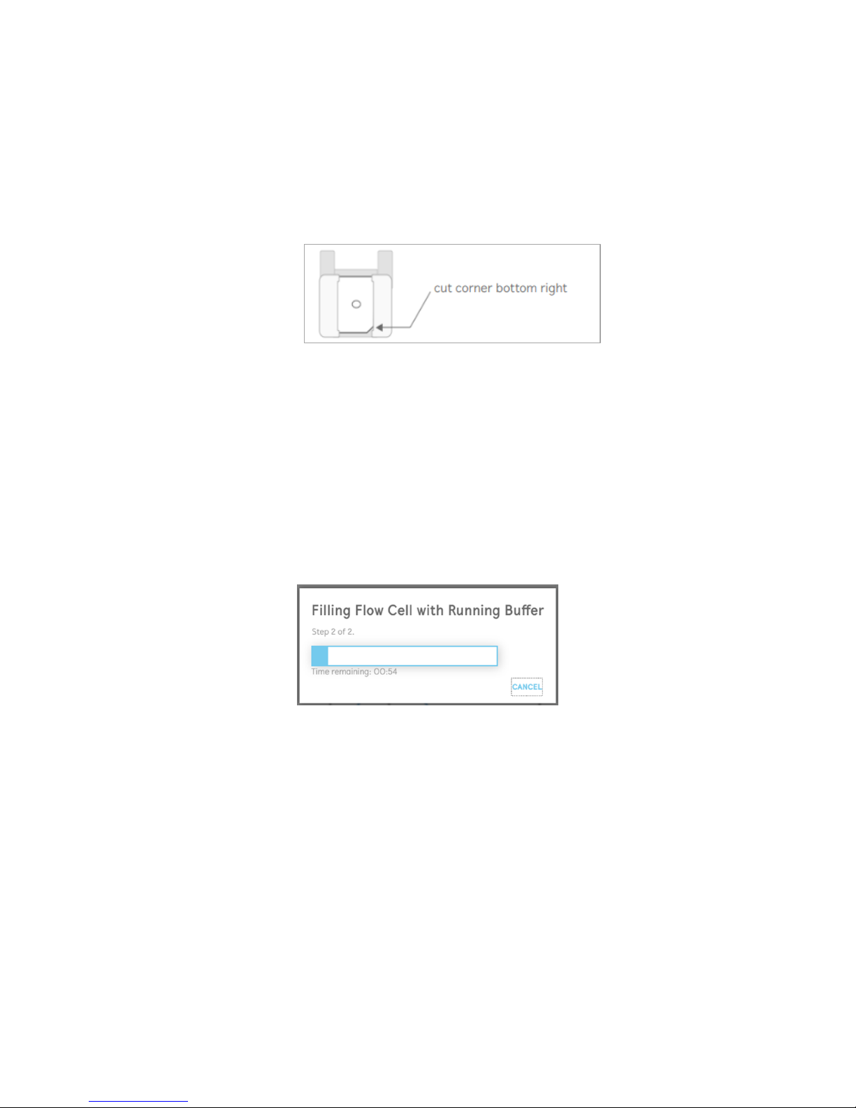
8. Carefully slide the sensor chip into the slot in the top of the sensor holder such that the
cut corner will be in the bottom right position when viewing the side of the holder
containing the slot [Figure 2.31]. If installed correctly, the glass chip will cover the entire
window, and the sensor will be fully seated into the bottom of the holder.
Figure 2.31 Proper installing of a sensor chip into the sensor holder.
9. Place the holder containing the sensor into the docking stage. Ensure it is fully seated
within the docking stage.
10. Close the lid of the OpenSPR, then click “Dock” to allow the sensor to be automatically
docked into place, creating a seal with the flow cell.
11. When the sensor is docked, click “Next” in the active prompt [Figure 2.28]. This will begin
flow of the running buffer into the flow cell. This process will take about 2 minutes to
complete, and a progress bar and timer will inform you of the time remaining [Figure
2.32].
Figure 2.32 Progress bar for filling flow cell with running buffer.
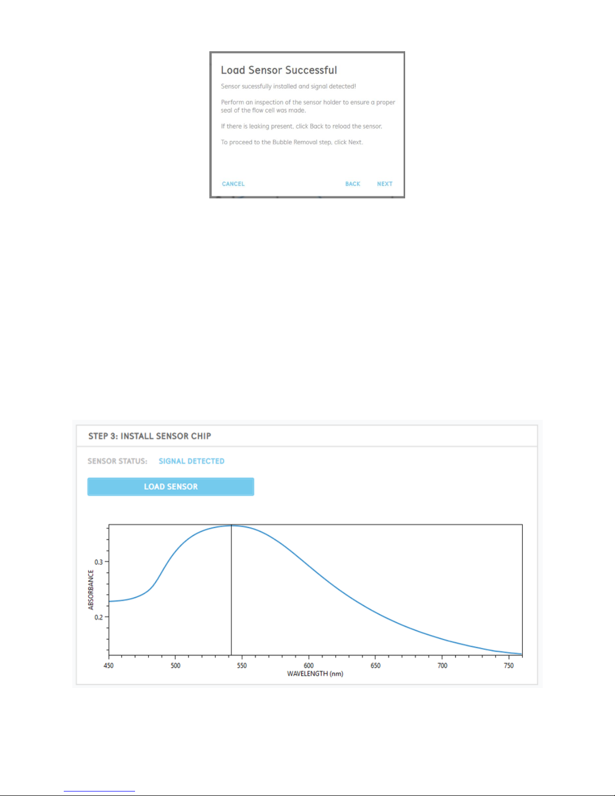
12. When the filling flow cell process is complete, the software will automatically check for
the detection of a sensor signal. A prompt will appear with the appropriate status [Figure
2.33].
Page 32
32
OpenSPR 1-Channel Operation Manual V4.1.01
Figure 2.33 Prompt after flow cell has been filled with running buffer (sensor successfully detected).
If a signal is successfully detected, perform an inspection at the base of the flow cell for
any accumulation of running buffer and leaking.
Leaking may occur if a proper seal is not made between the sensor and flow cell. If liquid
is present outside of the flow cell, select “Back” to begin the process to re-load the sensor.
If no leaking is present, select “Next” to proceed onto the bubble removal step (Section
2.4.2).
Once a sensor is loaded into the OpenSPR, an absorbance peak should be seen in the graph on
the main screen [Figure 2.34]. The center position of the absorbance peak should be near
approximately 550 nm.
Figure 2.34 Absorbance graph of a sensor installed into the OpenSPR.
Page 33
33
OpenSPR 1-Channel Operation Manual V4.1.01
2.4.2 Step 4: Bubble Removal and Prevention
It is important to remove and prevent any bubbles within the fluidic lines prior to starting your
test. Bubbles present in the system can cause interference with the sensor signal. The software
contains a semi-automated built-in procedure for removing bubbles. This procedure can be
accessed immediately following the load sensor process or can be started by selecting the
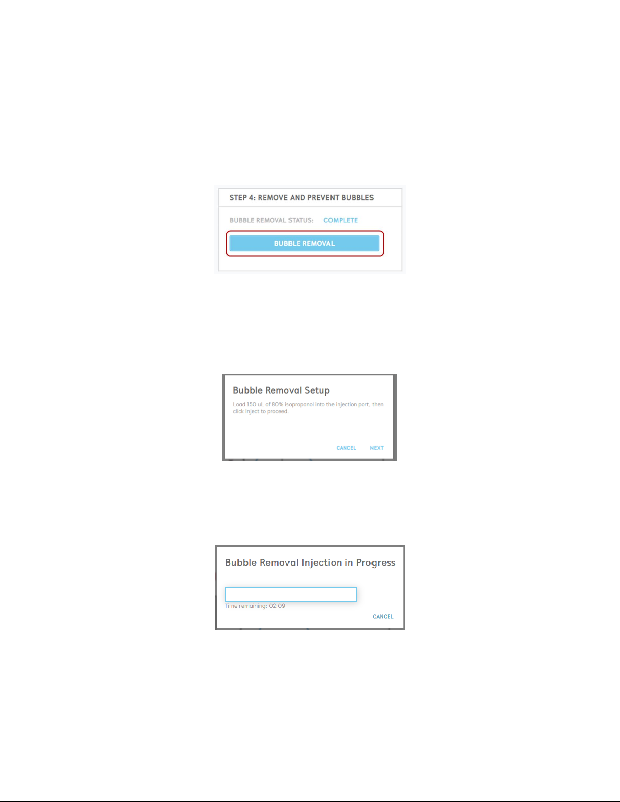
“Bubble Removal” button on the Sensor Setup Screen [Figure 2.35]. Details for the procedure are
found below.
Figure 2.35 Button to commence the bubble removal process.
1. To remove bubbles, a solution of 80% isopropanol will be used. The software will prompt
you to load this solution into the injection port – at least 150 µL volume is recommended
[Figure 2.36]. The solution should be introduced into the OpenSPR using a designated
syringe with a blunt-end injection tip.
Figure 2.36 Bubble Removal Setup prompt.
2. After the 80% isopropanol is loaded into the instrument, click “Next” to begin the
automated bubble removal procedure. This procedure will take approximately 2 minutes
to complete. The time remaining will be displayed with a progress bar [Figure 2.37].
Figure 2.37 Bubble removal progress dialogue.
During this period, the 80% isopropanol will be passed through the flow cell. The
decreased surface tension of the isopropanol solution will push out any pre-existing
bubbles towards the outlet waste.
Page 34
34
OpenSPR 1-Channel Operation Manual V4.1.01
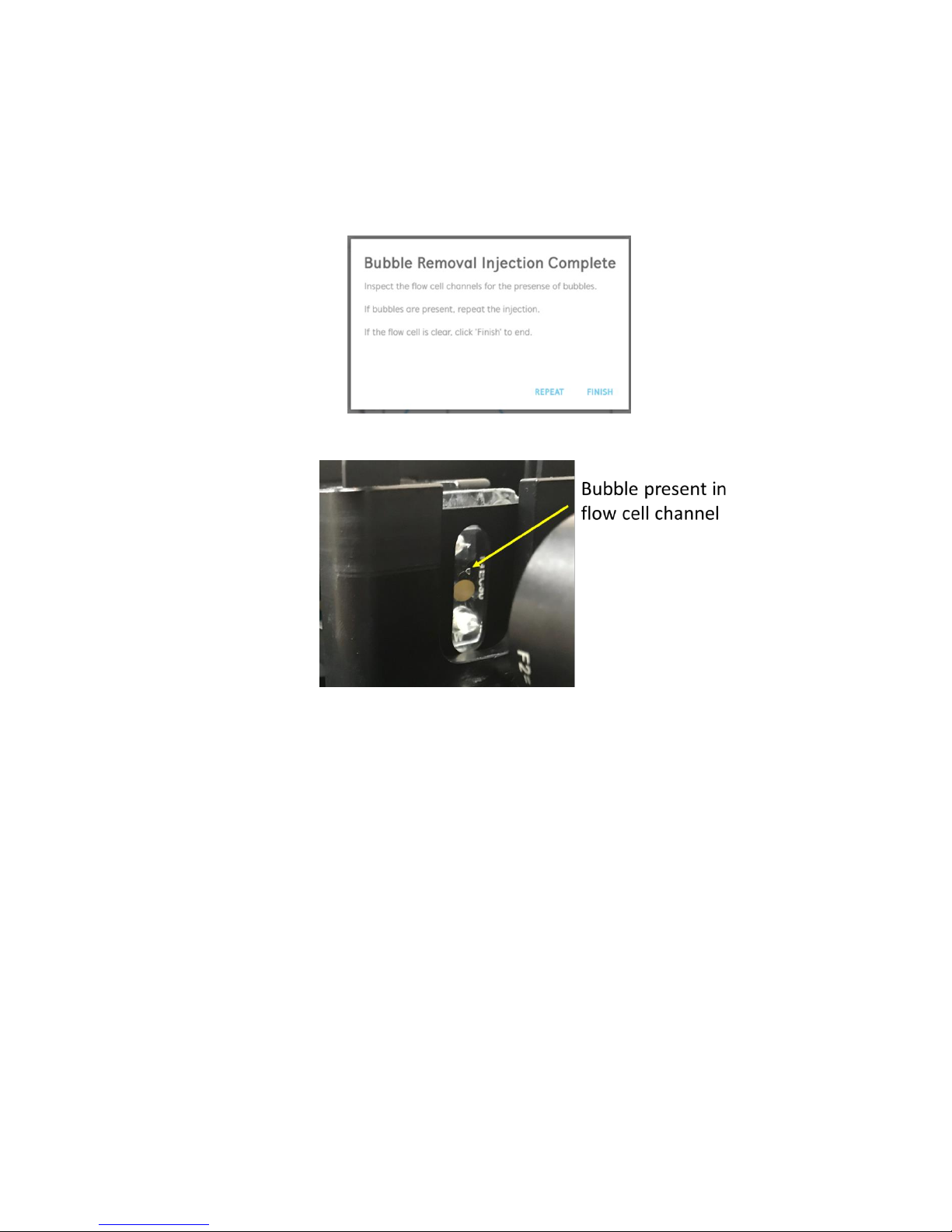
3. Once the bubble removal procedure is complete, you will be prompted to perform a visual
inspection of the flow cell [Figure 2.38]. You will want to look for the presence of any
bubbles within the full fluidic path – it is easiest to look for the outline of an air-liquid
interface [Figure 2.39]. If any bubbles are still present, click “Repeat”, which will bring you
back to the initial step, where you will need to load more isopropanol into the injection
port. Repeat this process until all bubbles are removed.
Figure 2.38 Bubble injection complete prompt.
Figure 2.39 Example of bubble present in flow cell channel.
4. Once the flow cell channels are clear, click “Finish” to end the process. The bubble
removal status will be updated accordingly on the main screen.
5. Prior to moving forward with your experiment, rinse the injection port with at least 0.5
mL of running buffer.
Page 35
35
OpenSPR 1-Channel Operation Manual V4.1.01
2.5 Running an Experiment
Once the sensor loading and bubble removal processes are complete, click “Next” in the
navigator located in the upper left of the menu bar. This will begin your test and data acquisition
will commence. The various stages of data acquisition and test options are explained below.
2.5.1 Test Name
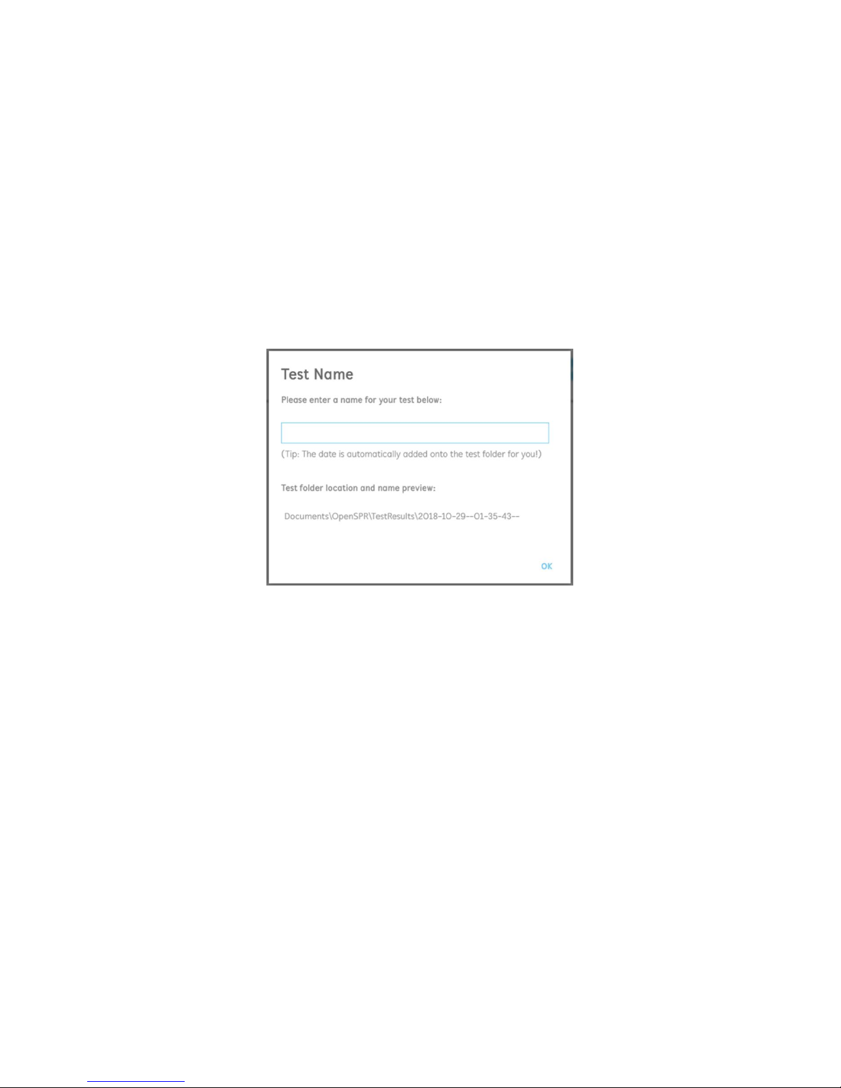
Upon beginning your test, you will be prompted to name your test [Figure 2.40]. This will name
the folder where all data for the test is saved. Note that the date and time of your test will be
automatically be appended onto the name. If a name is not given, then the test will be saved
simply under the date and time that it was started.
All data folders will be saved by default under Documents\OpenSPR\TestResults\.
Figure 2.40 Prompt to enter your test name.
2.5.2 Experiment Data Interface and Data Acquisition
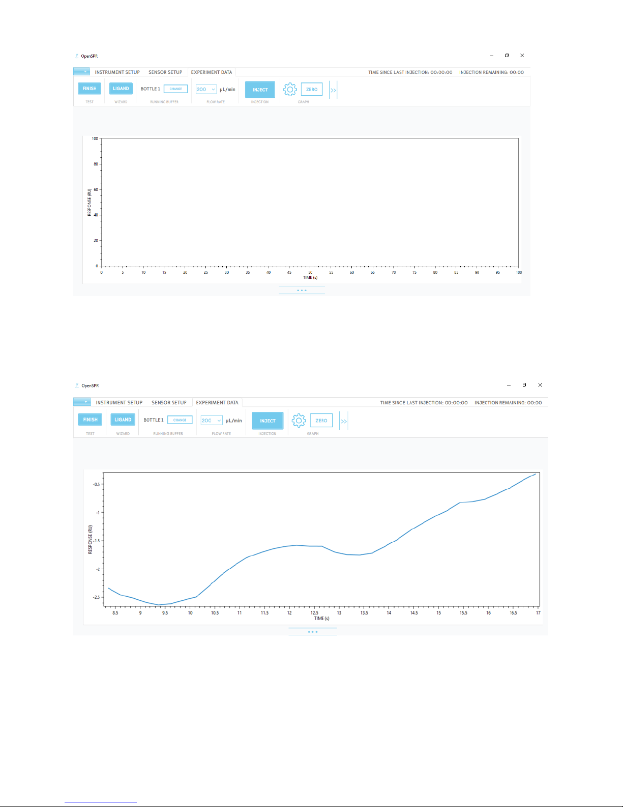
Upon starting a test, you will be introduced to the main test interface [Figure 2.41]. This interface
will allow you to control the various aspects of your OpenSPR instrument. Each aspect will be
described in detail in the sections below and how they relate to your experiment.
Page 36
36
OpenSPR 1-Channel Operation Manual V4.1.01
Figure 2.41 Experiment Data test interface.
After about 30 seconds, real-time data will begin streaming into the graph [Figure 2.42]. The axes
scales will start very small and will automatically grow to accommodate the data in both x and y
as data is collected. Approximately 4 points per second for each channel is being acquired.
Figure 2.42 Initial real-time data streaming into the response graph.
Page 37
37
OpenSPR 1-Channel Operation Manual V4.1.01
2.5.3 Changing the Running Buffer
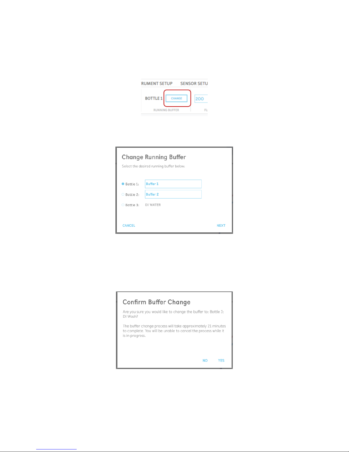
During an SPR experiment, in some scenarios a change of buffer may be needed. The OpenSPR
contains an automated process for changing the running buffer, which can be accessed by
selecting “Change Buffer” in the menu bar [Figure 2.43].
Figure 2.43 Button to begin the process to change the running buffer.
The user will be prompted to select the new running buffer to change to [Figure 2.44].
Figure 2.44 Buffer change dialogue prompt.
Prior to commencing the automated buffer change process, a confirmation will appear asking the
user to ensure enough running buffer is filled into the correct bottle with the proper tubing
installed (see Section 2.1.2 for more details) [Figure 2.45]. Note that the process to change the
buffers will take approximately 16 mL to fully flush the system.
Figure 2.45 Confirmation of buffer change.
Page 38
38
OpenSPR 1-Channel Operation Manual V4.1.01
The buffer change procedure will take approximately 21 minutes to complete to fully exchange
the buffer in the system. During this process, it is recommended to flush at least 2 mL of the new
running buffer through the injection port.
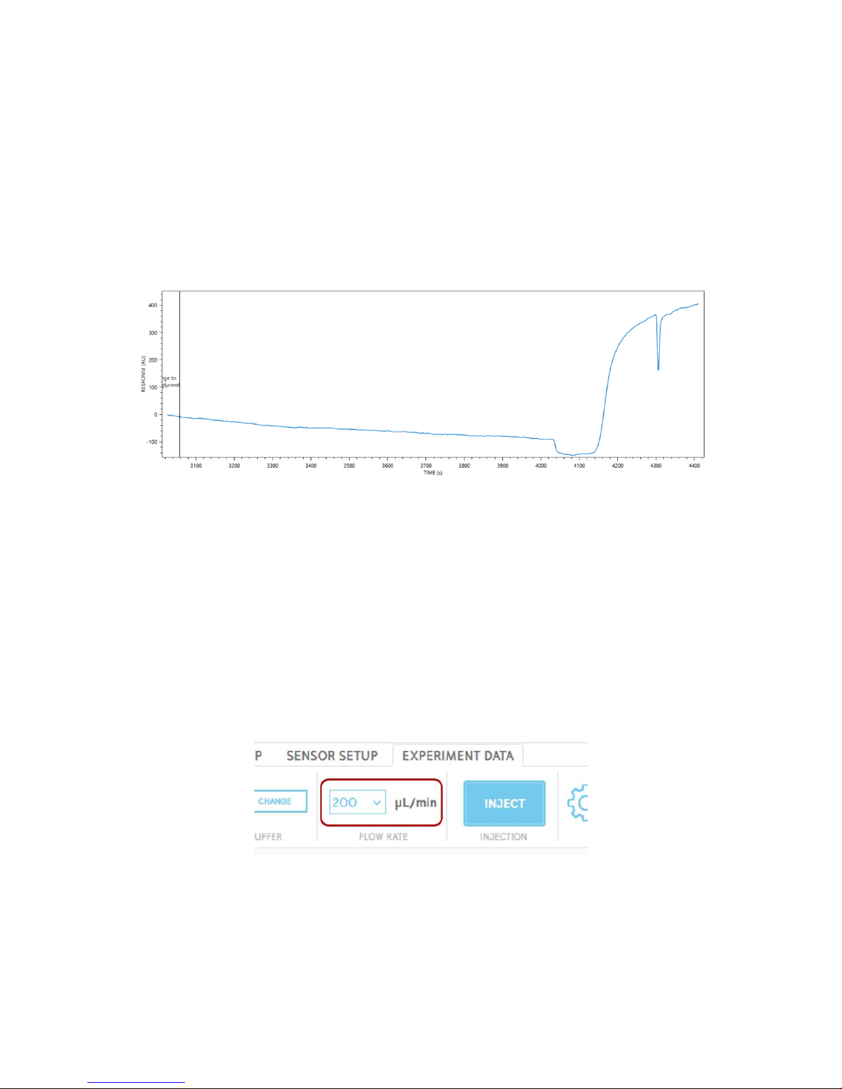
The buffer change event will be marked on the timeline with a solid line. The response signal will
change during the last 5 minutes of the buffer change process, depending on the refractive index
of the new buffer compared to the original. For example, if the refractive index of the new buffer
is higher than the original, this will result in an increase in the response baseline. A brief increase
or decrease in the response signal will be observed near the end of the buffer change process
when a separate fluidic line in the OpenSPR is flushed.
Figure 2.46 Example response graph of a buffer change to a higher refractive index running buffer.
Once the buffer change procedure is complete, the current working running buffer bottle will be
shown in the menu bar. It may take additional time for the baseline to equilibrize to the new
running buffer – it is recommended to wait until the baseline has stabilized until moving forward
with your experiment.
2.5.4 Flow Rate Controls
During a test, the user can change the flow rate in real time by using the drop-down menu located
in the menu bar [Figure 2.47]. The flow rate is used to control the interaction time of a sample
injection with the sensor.
Figure 2.47 Flow rate drop-down menu.
The interaction time of a sample injection is calculated based on the size of the sample loop
installed in the OpenSPR as well as flow rate:
Page 39

39
OpenSPR 1-Channel Operation Manual V4.1.01
𝑆𝑎𝑚𝑝𝑙𝑒 𝑖𝑛𝑡𝑒𝑟𝑎𝑐𝑡𝑖𝑜𝑛 𝑡𝑖𝑚𝑒 (min)=
𝑆𝑎𝑚𝑝𝑙𝑒 𝑙𝑜𝑜𝑝 𝑣𝑜𝑙𝑢𝑚𝑒 (μL
)
𝐹𝑙𝑜𝑤 𝑟𝑎𝑡𝑒 (μL min )
⁄
The standard sample loop that comes installed in the OpenSPR is 100 µL in volume.
For different injection types and instances in your experiment, it can be advantageous to use
different flow rates. A table of example scenarios and recommended flow rates is provided
below:
Table 3 Recommended typical flow rates for different injection types and experimental scenarios.
Injection Type / Scenario
Recommended Typical Flow
Rate
Baseline equilibration
200 µL/min
Surface Conditioning
150 µL/min
Surface Activation/Blocking
20 µL/min
Ligand Immobilization
5 - 20 µL/min
Analyte
20 - 50 µL/min
Regeneration
100 - 200 µL/min
2.5.5 Injections
Samples will be introduced to the sensor inside the OpenSPR using injections. The OpenSPR
contains a semi-automated injection procedure; introduction of the sample into the OpenSPR
instrument will be performed by the user, and then the exposure of the sample towards the
sensor will be automatically controlled via the software. This section will outline the full injection
process.
Syringes and tips:
User samples and solutions are introduced into the OpenSPR using syringes containing blunt-end
injection tips. It is important that only blunt-end injection tips are used, as pointed tips will
damage the seal of the injection port within the instrument. Nicoya Lifesciences offers two
types of syringes, both disposable and glass.
Disposable syringes (SYR-PL-50) are 1 mL in volume and have a luer-lock fitting to be used with
luer-lock disposable blunt injection tips (TIP-BLUNT-50). These syringes are recommended to be
used for general solutions where precise volume control is not required, such as 80% isopropanol,
regeneration solutions, and rinsing with running buffer. Note that these syringes are not
compatible with DMSO. With the disposable syringes, it is recommended to allocate a unique
syringe for each solution type to prevent cross-contamination. When loading solutions into the
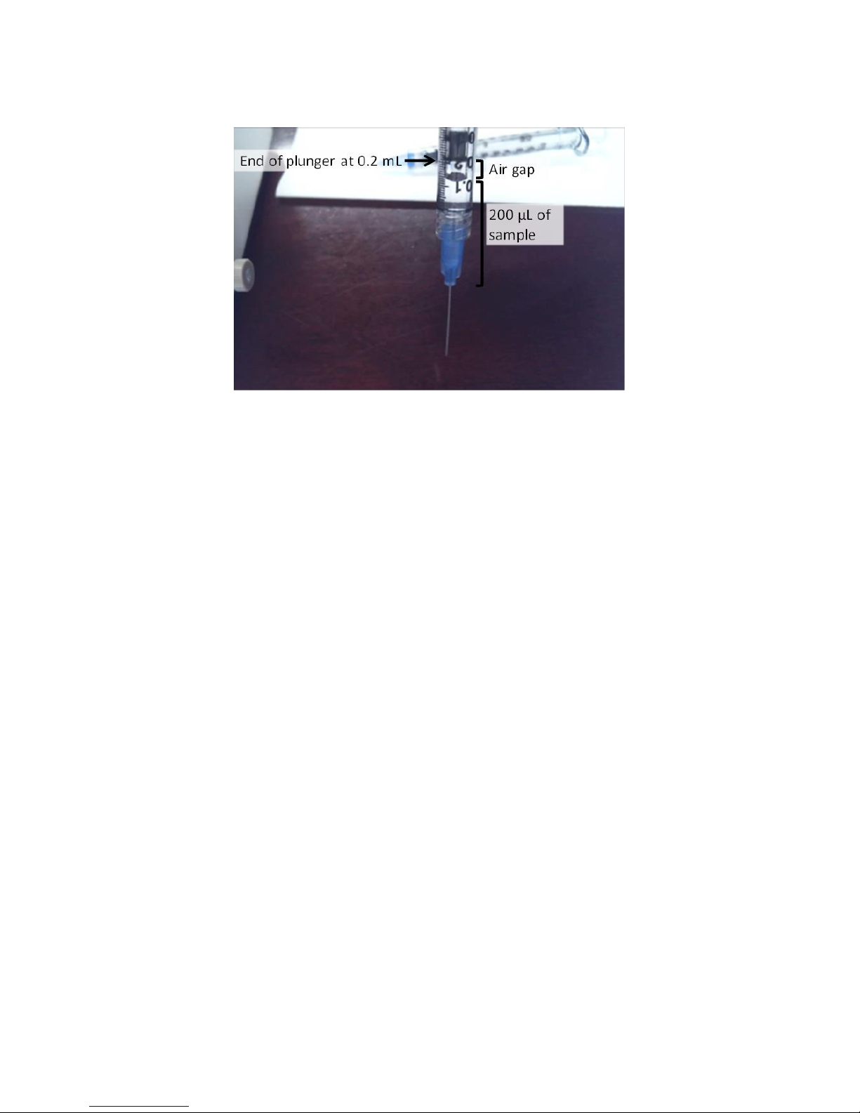
disposable syringes, note that there will be a dead-volume present in the injection tip, so an air
gap of ~100 µL will be contained within the syringe. This air gap can remain within the syringe so
Page 40
40
OpenSPR 1-Channel Operation Manual V4.1.01
long as it stays on the plunger side and is not introduced into the OpenSPR with your sample
[Figure 2.48].
Figure 2.48 Example of loading sample into disposable plastic syringe with air gap.
Glass syringes (SYR-G) are 250 µL in volume and come installed with a gastight blunt-end injection
tip which does not contain a dead volume (replacement needles are also available, RN-G-6).
These syringes are recommended to be used for performing injection of biological samples
(ligand and analyte), where precise volume control at 150 µL is desired. If using the same glass
syringe for multiple samples, it is recommended to rinse the syringe thoroughly with running
buffer between samples.
Volume for Sample Injection:
The amount of sample volume required for an injection is dependent on the size of sample loop
installed in the OpenSPR. The minimum sample volume required is the volume of the sample
loop + 50 µL. Excess volume in addition to that of the sample loop is required to ensure a uniform
sample concentration profile and prevent air from remaining within the sample loop.
The standard size of sample loop provided is 100 µL in volume. The minimum injection volume
for a 100 µL sample loop is 150 µL.
For general solutions such as 80% isopropanol, regeneration buffers, etc it is recommended to
use excess volume to prevent user error in the injection process when possible.
Injection Process:
1. Rinse the injection port and sample loop with running buffer to flush any previous
sample/solution from the sample loop fluidic lines.
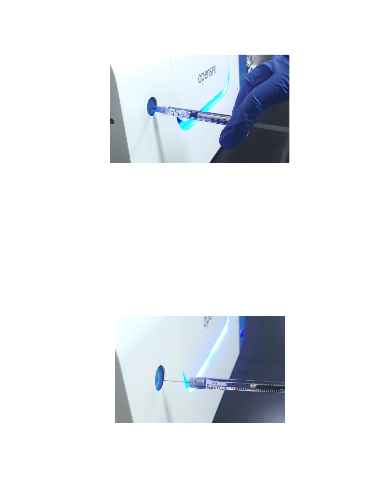
To do this, fill a syringe (designated for the running buffer) with at least 0.5 mL of the
running buffer*. Insert the blunt tipped syringe fully into the injection port making sure it
is seated, then slowly depress the plunger allowing all the running buffer to be passed
Page 41
41
OpenSPR 1-Channel Operation Manual V4.1.01
through into the instrument [Figure 2.49]. The excess buffer will exit the Sample outlet
tube into the waste bottle.
Figure 2.49 Disposable syringe properly seated into injection port for buffer rinsing.
* Some conditions may require additional rinsing to completely clean the sample loop to
avoid cross contamination.
2. Purge the Sample Loop with air.
Using the same buffer syringe, draw 0.5-1 mL of air in the syringe then insert the blunt
tipped needle into the injection port and push the air through the sample loop. The excess
buffer and eventually will exit via the outlet line, followed by air.
3. Load a syringe with the sample/solution to inject. For a standard 100 µL sample loop, at
least 150 µL of sample is required.
Insert the blunt tipped syringe fully into the injection port making sure it is seated, then
slowly depress the plunger to introduce your sample into the instrument [Figure 2.50].
Before removing the syringe from the injection port, wait at least 5 seconds with the
syringe stationary for the fluidic pressure to stabilize in the sample loop.
Figure 2.50 Glass syringe for 150 µL sample volume properly seated into OpenSPR.
Page 42
42
OpenSPR 1-Channel Operation Manual V4.1.01
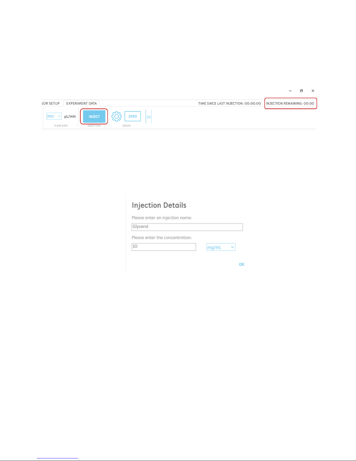
4. Click “Inject” in the software to introduce your sample over the sensor [Figure 2.51]. At
this time, the OpenSPR will automatically introduce your sample loaded into the sample
loop into the running buffer flow to be exposed over the sensor. Other instrument
functions will be disabled in the software during this time until the injection is complete.
The time remaining in the injection will be shown in the upper right corner of the software
for the user to reference.
Figure 2.51 Click the inject button to introduce your sample over the sensor. The time remaining in the injection is shown above
the menu bar.
5. When an injection is made, an Injection Details box will appear [Figure 2.52]. In this box,
the user can input the sample name as well as the concentration. It is highly
recommended to fill in these details as it will be used to identify the injection in the data
analysis.
Figure 2.52 Injection details box to fill in sample name and concentration.
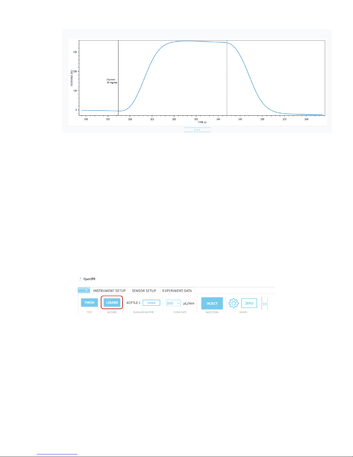
Clicking “Ok” will log the injection, and the injection will be labelled appropriately on the
graph. Injections will also be labelled with 2 lines; a solid line when the injection begins,
and then a dotted line when the injection is complete [Figure 2.53]. After the injection is
complete, the sample will be replaced with running buffer.
Page 43
43
OpenSPR 1-Channel Operation Manual V4.1.01
Figure 2.53 Solid and dotted lines on the response graph marking the beginning and end of the injection period.
The user will not be able to perform other instrument functions during the injection
period.
6. Only after the injection is complete and the baseline has settled should the user move
onto the next injection, repeating this procedure.
2.5.6 Ligand Immobilization Wizard
The OpenSPR software contains a built-in ligand immobilization wizard which walks the user
though the recommended procedures for immobilization of a ligand onto the various sensor
chemistries available.
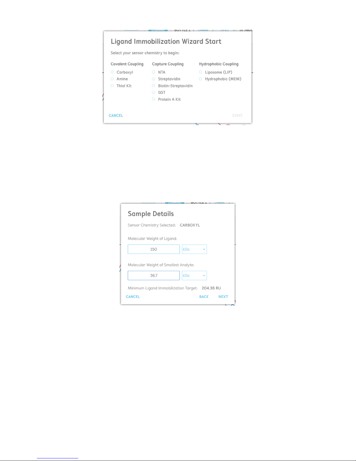
The ligand immobilization wizard can be accessed by clicking the “Ligand” button in the wizard
section of the menu bar [Figure 2.54].
Figure 2.54 Button to access the ligand wizard in the menu bar.
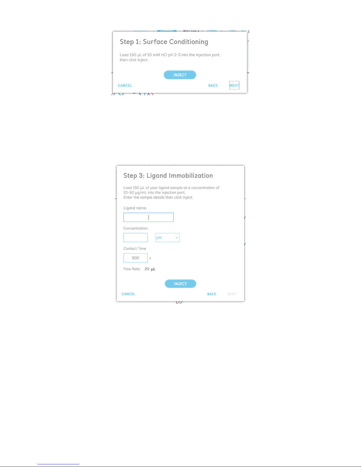
Upon opening the wizard, the user will first be prompted to select the desired sensor chemistry
[Figure 2.55]. Each chemistry will have a unique built-in protocol of for the user to follow. The
protocol will walk the user through the various injections needed (surface clearing, surface
activation, etc) with built-in controls for the recommended flow rates and channel settings.
Page 44
44
OpenSPR 1-Channel Operation Manual V4.1.01
Figure 2.55 Ligand wizard starting step: select a sensor chemistry to begin.
After selecting your desired sensor chemistry, the user will be asked to enter in the molecular
weights of their samples to be used for kinetic analysis [Figure 2.56]. The ligand is the biomolecule
being immobilized onto the sensor surface, while the analyte is the second binding partner which
will be free-flowing in solution. Based on the relative molecular weights, the software will
calculate the theoretical minimum ligand immobilization target to obtain sufficient analyte signal
for analysis.
Figure 2.56 Enter in the molecular weights of your biomolecules into the ligand wizard.
After this step, the specific protocols for each sensor chemistry will begin. Each step will indicate
the recommended solution to be loaded into the instrument, and the injections will be
performed right from the dialogue box [Figure 2.57]. It is recommended to keep the dialogue
boxes open throughout the injection processes otherwise the position in the wizard will be lost.
Once an injection is complete, the user can click “Next” to move onto the following step. Prior to
performing the subsequent injection, it is recommended that the user waits until the baseline
stabilizes from the previous injection.
Page 45
45
OpenSPR 1-Channel Operation Manual V4.1.01
Figure 2.57 Example dialogue box containing injection instructions and inject button.
When the user reaches the Ligand Immobilization step, they will be prompted to enter their
ligand details, including the name and concentration [Figure 2.58]. The user can also set the
contact time manually if desired. Note that the contact time will be dependent on the sample
loop volume installed in the instrument. For a 100 µL sample loop, for most applications a 300 s
contact time is recommended, but the time can be adjusted from 1200 – 30 s.
Figure 2.58 Ligand immobilization injection stage.
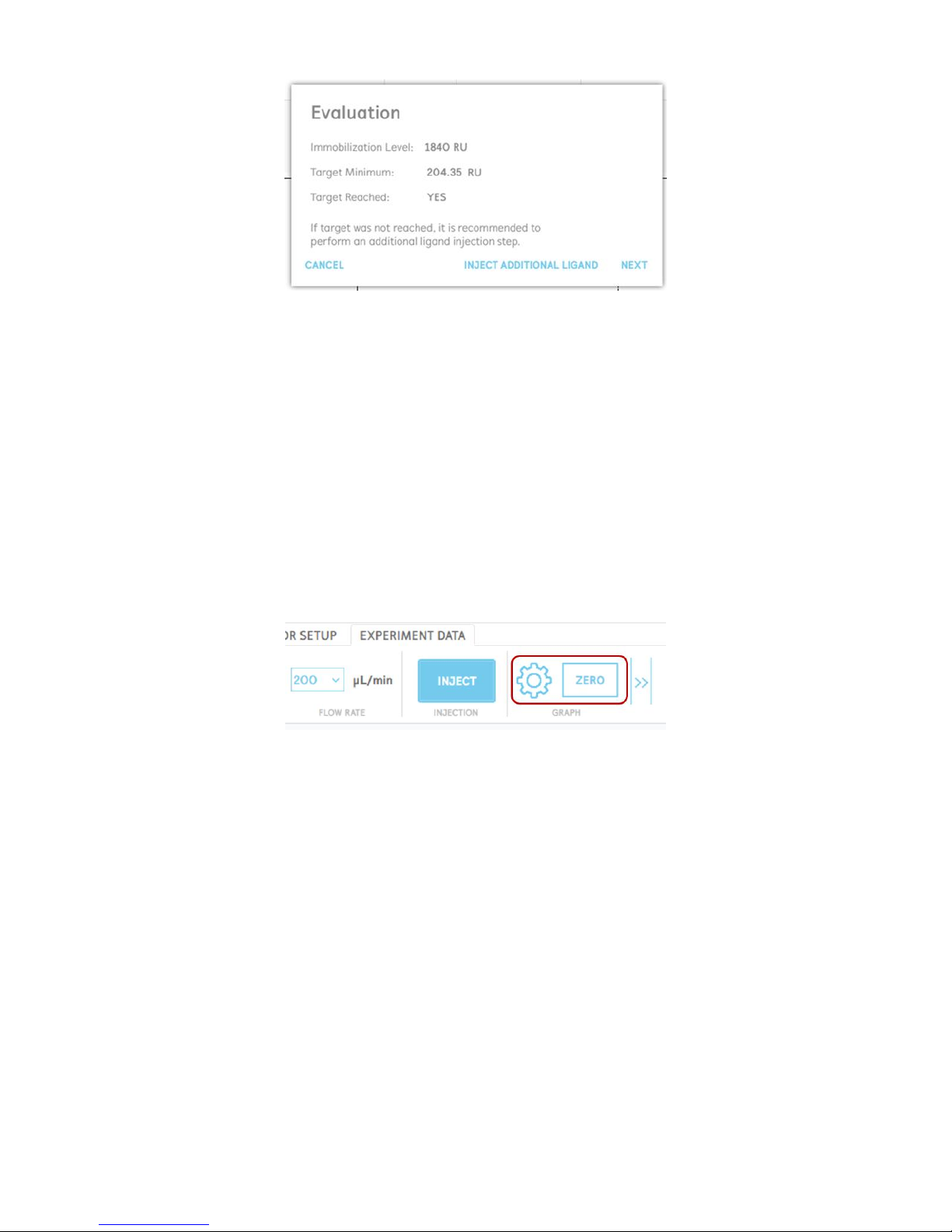
Upon performing the ligand injection, the wizard will automatically move forward onto the
evaluation stage [Figure 2.59]. The software will automatically evaluate the amount of ligand
immobilization obtained and will compare it against the minimum immobilization target level
determined at the start of the wizard. If enough ligand immobilization was obtained, the user can
move onto the next step. If not, it is recommended that the user repeats another injection of the
ligand. If the ligand immobilization level achieved is significantly lower than the target, the user
should attempt to increase the concentration of the ligand used.
Page 46
46
OpenSPR 1-Channel Operation Manual V4.1.01
Figure 2.59 Ligand evaluation stage.
Once the ligand immobilization is complete, the user will return to the main screen. It is
recommended to zero the baseline at this time (see Section 2.5.7) prior to beginning analyte
injection analysis.
2.5.7 Graph Settings
The user has the flexibility to customize the view of the response graph in real time throughout
the experiment. The primary graph controls are accessed in the menu bar of the main screen
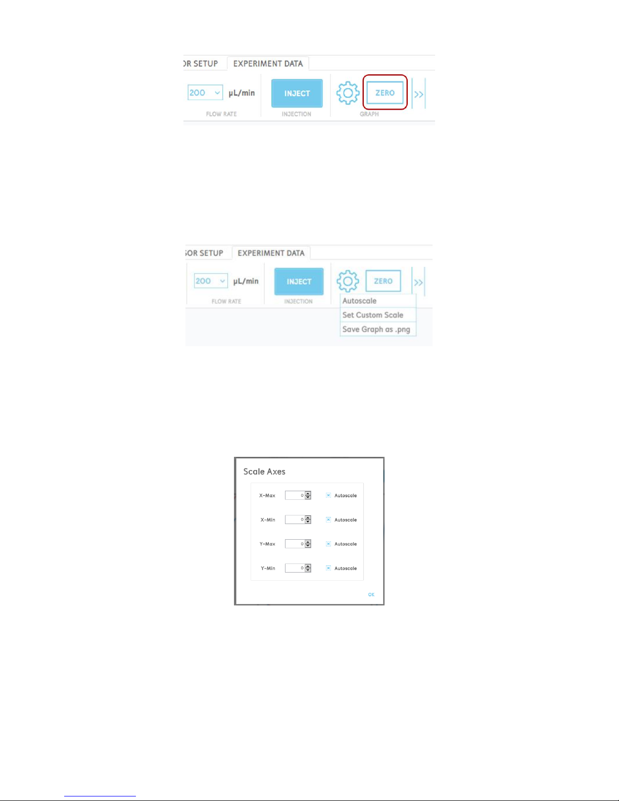
[Figure 2.60]. In the menu, the user can zero the graph, as well as open advanced settings to
manually adjust the axes scale.
Figure 2.60 Graph controls in menu bar.
Zeroing the Graph
Clicking “Zero” in the graph menu [Figure 2.61] will clear all the data points from the graph and
will normalize the response tracking to zero on the y-axis. All the previously collected data is still
saved to the data file but is only no longer being displayed on the graph.
Zeroing the graph is recommended at any stage in the experiment where a new baseline is
established, and the user wants to make a relative comparison for subsequent injections. An
example of this scenario is after the ligand immobilization step, and before injection of analyte
for analysis.
Page 47
47
OpenSPR 1-Channel Operation Manual V4.1.01
Figure 2.61 Button to zero the graph in the menu bar.
Advanced Graph Controls
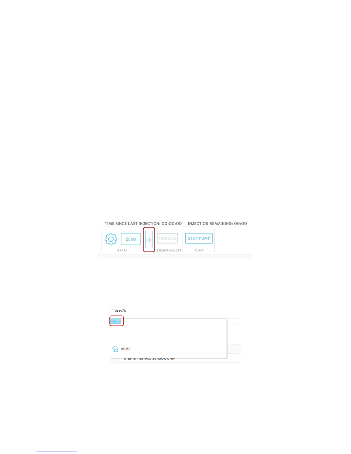
By clicking the gear (settings) button in the graph menu, the user will have the options to
autoscale the graph, set custom axes, and save an image of the graph [Figure 2.62].
Figure 2.62 Graph settings menu.
Autoscaling the graph will return the x and y-axis scales back to the default values to encompass
all of the data displayed in the graph.
Selecting “Set Custom Axes” will open a menu which will allow you to manually set the minimum
and maximum values of both the x and y-axes [Figure 2.63].
Figure 2.63 Set custom axes menu.
Manual Adjustment of the Graph
The response graph axes will autoscale by default as the data points are collected and the signal
changes. However, it can be desirable to zoom in or out on certain areas of the graph as the test
progresses. The various functions of manually adjusting the graph are described below:
Page 48
48
OpenSPR 1-Channel Operation Manual V4.1.01
• The graph can be moved in the x and y axis by holding the left mouse button and dragging
the mouse.
• The graph can be zoomed in and out by using the scroll wheel on a mouse, or the pinching
and expanding finger gestures on a trackpad.
• A single axis can be scaled by hovering the mouse on either the x or y axis, while using a
scroll wheel on a mouse or the pinching and expanding finger gestures on a trackpad.
• The graph can be zoomed in and out by holding the middle mouse button and selecting a
boxed area to zoom in to.
• The axes minimum and maximum values of the graph can be individually assigned by
using the advanced controls (see section above)
2.5.8 Advanced Controls
On the right-hand side of the menu bar, there is a bar which allows you to open advanced
instrument controls [Figure 2.64]. Normally during a test, the user should not have to use these,
but they do give flexibility when a special circumstance arises, or troubleshooting is needed.
Namely, the user will have to ability to start and stop the flow in the OpenSPR, and when the flow
is stopped, the user can then undock and dock the sensor stage. Typically, these controls should
only be used if leaking arises from the flow cell during a test.
Figure 2.64 Advanced controls menu open.
Additional advanced options can be accessed through the arrow at the top left of the menu bar
[Figure 2.67]. In here, the user has the ability to return back to the home screen by selecting the
“Home” option. This option can be accessed at any point within the software environment.
Figure 2.65 Advanced options menu located in top left of menu bar.
Page 49
49
OpenSPR 1-Channel Operation Manual V4.1.01
2.6 Shutdown Procedures
2.6.1 Ending a Test
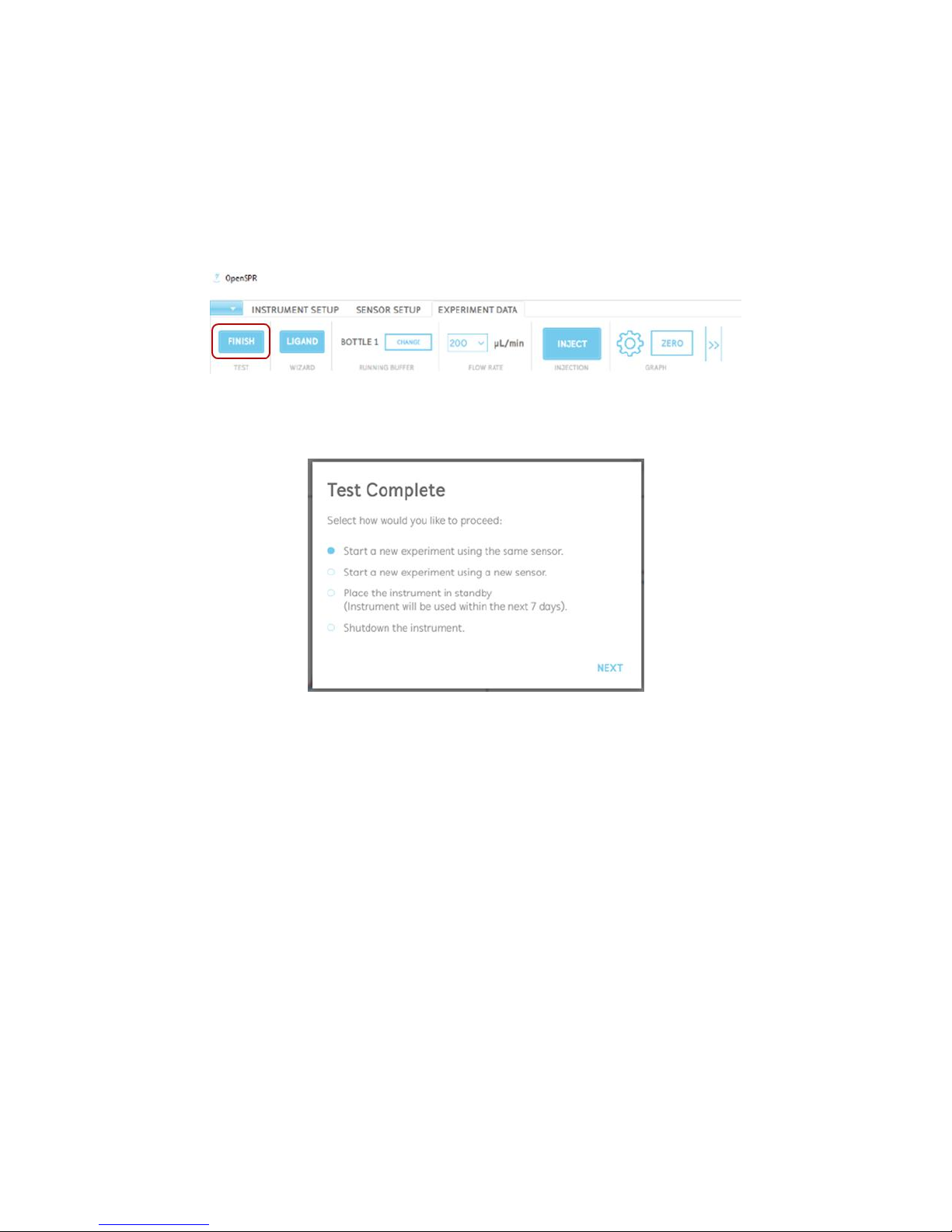
To end your SPR experiment, you must click the “Finish” button in the upper left corner of the
menu bar [Figure 2.66]. A window will appear asking to you confirm that you would like the finish
the test. Accepting this will finalize all the data files and will create additional files formatted for
data analysis in TraceDrawer.
Figure 2.66 Finish button to end a test and create the final data files.
After the data files are saved, the software will give you several options to proceed [Figure 2.67]:
Figure 2.67 Test complete window with options on how to proceed after the test.
1) Start a new experiment using the same sensor: this option will create a new test and will
restart the data acquisition on the Experiment Data screen. This option is great if you
want to perform a quick data analysis to evaluate the results collected while still being
able to continue testing on the same sensor.
2) Start a new experiment using a new sensor: This option should be selected if the user
wants to start a new SPR experiment using a new sensor. It will create a new test and will
bring the user back to the Instrument Setup screen, allowing them to change the sensor.
3) Place the instrument into standby mode: This option should be selected if the user is
finished running tests for the day. This mode will guide you through the steps to safely
store your instrument until you run your next test. Full details are provided in Section
2.6.2.
4) Shutdown the instrument: This option should be selected if the user does not plan to use
the instrument in the near future and would like to shut it down. This will guide the user
Page 50
50
OpenSPR 1-Channel Operation Manual V4.1.01
through the steps to prepare the instrument for shutdown. Full details are provided in
Section 2.6.3.
2.6.2 Standby Mode
When the user has ended testing for the day, it is important to place the OpenSPR into standby
mode for proper maintenance of the OpenSPR. Standby mode will set up the instrument under
a constant low flow rate (5 µL/min) which will prevent any buildup or blockages in the fluidic
lines. To prepare the instrument for standby mode, the software will guide the user through
several steps to prepare the instrument. The steps are outlined below:
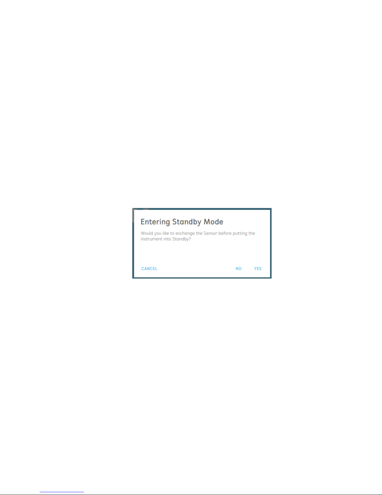
1. The user will first be asked if they would like to exchange the sensor prior to placing the
instrument into standby mode [Figure 2.68].
If the user would like to continue using the same sensor for analysis in subsequent tests,
it is recommended to leave the sensor installed in the OpenSPR during standby mode.
If the sensor is no longer going to be used for subsequent testing, it can be removed and
replaced with a blank chip at this time. If the user selects this option, they will be guided
through the process of replacing the sensor chip.
Figure 2.68 Entering standby mode option to change the sensor chip.
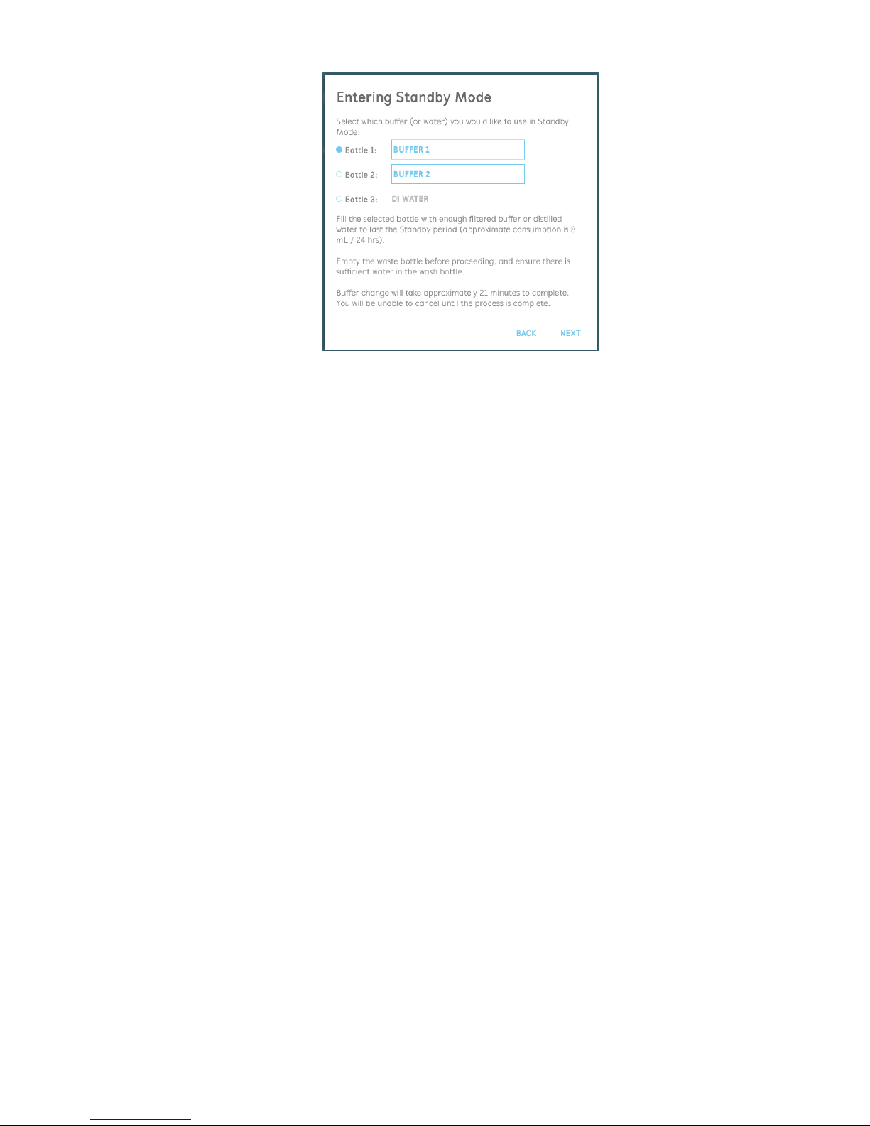
2. Next, the user will be prompted to select the bottle and buffer solution in which they
would like to use in the instrument while in standby mode [Figure 2.69].
If the user is keeping a functionalized sensor within the OpenSPR for subsequent testing,
it is recommended to place the instrument into Standby Mode with the biological running
buffer.
Otherwise, if a blank chip is installed in the instrument or if the sensor is no longer going
to be used, DI Water should be used for standby mode.
Page 51
51
OpenSPR 1-Channel Operation Manual V4.1.01
Figure 2.69 Selection of running buffer bottle to place the instrument into standby mode.
Note: Standby mode will use consume approximately 8 mL of running buffer or distilled
water / 24 hrs. Prior to entering standby mode, ensure sufficient solutions are present in
the buffer bottles.
3. Once the standby buffer is selected, the instrument will perform an initial rinsing
procedure. This will take approximately 21 minutes to complete. During this time, the
user must rinse out the injection port with at least 3 mL
4. When the rinsing procedure is complete, the instrument will enter standby mode and the
software will remain on the home screen. The status of the instrument will be displayed,
and the instrument can be left unattended.
Important: Do not shut down the software or the OpenSPR instrument while in standby
mode.
2.6.3 Instrument Shutdown
Prior to shutting down the instrument, it is important to thoroughly rinse and sterilize the tubing
to maintain proper performance of the OpenSPR.
The shutdown procedure will require the following supplies:
• At least 20 mL of filtered deionized water
• At least 20 mL of 80% isopropanol
• Blank chip
• 2x syringes for rinsing the injection port with deionized water and 80% isopropanol
The full shutdown procedure will take approximately 90 minutes to complete and consists of 3
steps: a rinse with deionized water, sterilization with 80% isopropanol, followed by purging of
the pumps and tubing with air. It is recommended to empty the waste bottle prior to beginning
Page 52
52
OpenSPR 1-Channel Operation Manual V4.1.01
the shutdown procedure to prevent overflow. The software will guide the user through the
shutdown procedure, detailed below:
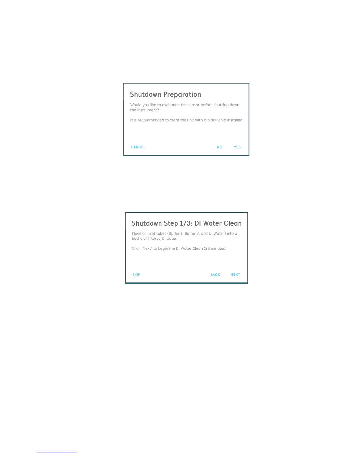
1. The user will first be asked if they would like to exchange the sensor [Figure 2.70]. It is
recommended to install a blank chip for instrument shutdown. Selecting “Yes” will guide
the user through the process to exchange the sensor.
Figure 2.70 Prompt to exchange the sensor. It is recommended to install a blank sensor for instrument shutdown.
2. The first step in the shutdown process will be to rinse the system with filtered deionized
water [Figure 2.71]. To do this, place all 3 inlet tubes into a bottle containing filtered
deionized water (multiple bottles can be used as necessary, so long as all inlet tubes are
submerged). Once all inlet tubes are submerged, click “Next” to begin the rinsing step.
Figure 2.71 Shutdown process 1/3: flush the instrument with deionized water.
3. A progress bar will display the rinsing step status. During this time, rinse the injection port
with at least 5 mL of filtered deionized water.
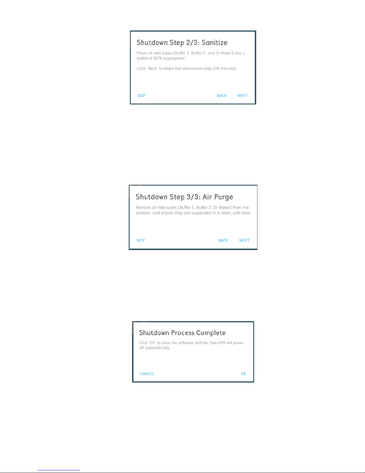
4. The second step in the shutdown process will be to sterilize the system with 80%
isopropanol [Figure 2.72]. To do this, place all 3 inlet tubes into a bottle containing 80%
isopropanol (multiple bottles can be used as necessary, so long as all inlet tubes are
submerged). Once all inlet tubes are submerged, click “Next” to begin the sterilization
step.
Page 53
53
OpenSPR 1-Channel Operation Manual V4.1.01
Figure 2.72 Shutdown process 2/3: Sterilization with 80% isopropanol.
5. A progress bar will display the sterilization step status. During this time, rinse the injection
port with at least 5 mL of 80% isopropanol.
6. The third step in the shutdown process will be to purge the pumps and tubing of the
system with air [Figure 2.73]. To do this, remove all 3 inlet tubes from solution and
suspend the ends of the tubes in a clean, safe space. Once all inlet tubes are in proper
position, click “Next” to begin the purging step.
Figure 2.73 Shutdown process 3/3: purging with air.
7. A progress bar will display the status of the purging step. During this time, purge the
injection port with at least 2 mL of air.
8. Once the shutdown preparation processes are complete, a final dialogue box will appear
[Figure 2.74]. Clicking “OK” in this dialogue will safely close the software and power off
the OpenSPR instrument automatically.
Figure 2.74 Shutdown process complete.
Page 54
54
OpenSPR 1-Channel Operation Manual V4.1.01
2.7 Data Output Files
Once an experiment is complete and the user finishes the test, several types of data files are
created into a test folder. The test folder will always be saved under:
Documents\OpenSPR\TestResults\ and will have the name given at the beginning of the test
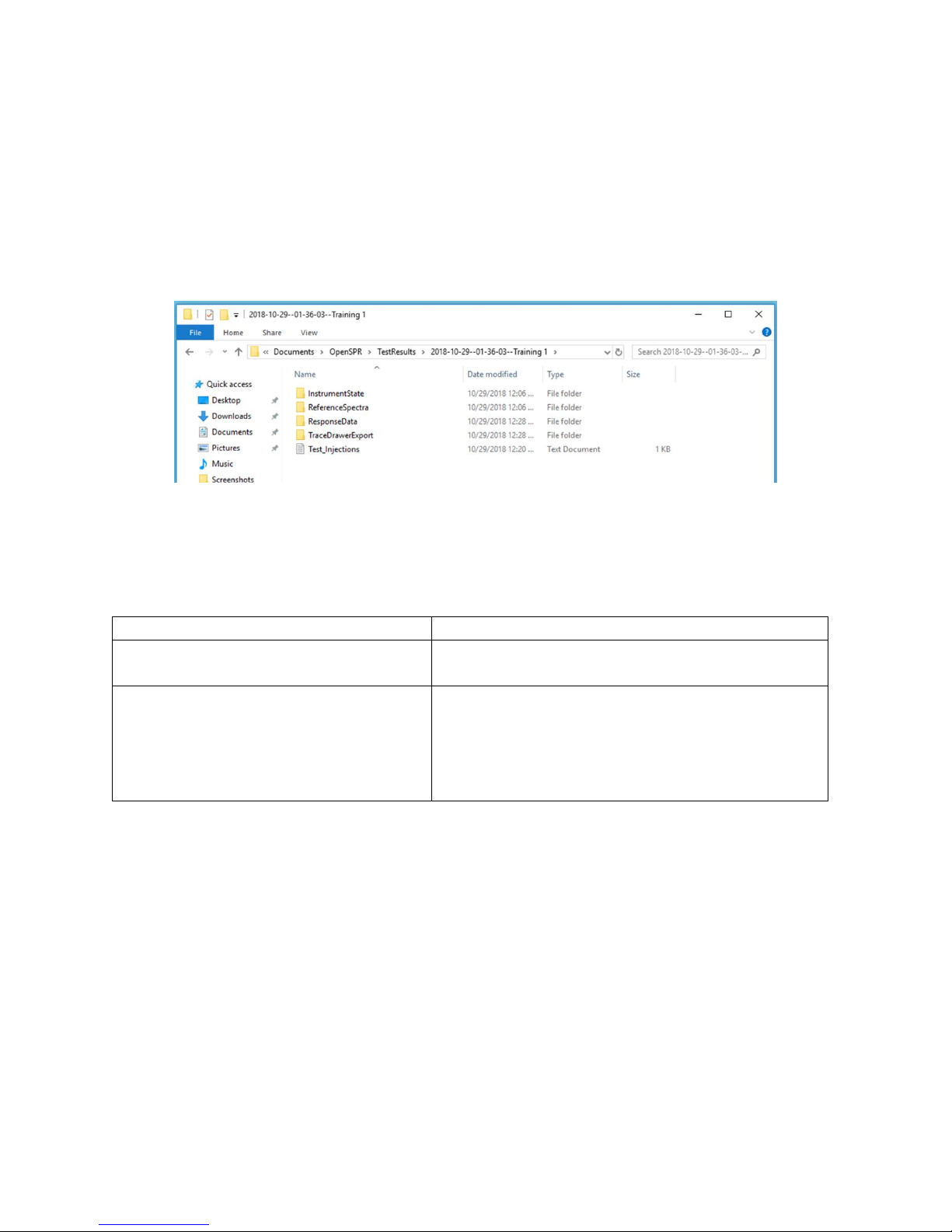
(Section 2.5.1). An example of contents of the test folder is shown below [Figure 2.75].
Figure 2.75 Data output folders and files created from a test.
The data files formatted for kinetic analysis are in the folder named “TraceDrawerExport”. In
these files, all injections have been separated and normalized in both the X and Y scales. Inside
this folder, you will find several files which are detailed below:
File
Details
Test Date--Time--Filename_CH1
Response data for each injection normalized for
kinetic analysis.
Test Date--Time-Filename_FullTestPreview
This is a file that has been formatted to import the
full test sequence into TraceDrawer as a single
injection. It is useful for reviewing the continual
test sequence and is not formatted for kinetic
analysis.
For kinetic analysis, it is recommended to use the CH1 file format for analysis. The procedure for
performing a kinetic analysis can be found in the TraceDrawer Kinetic Analysis Guide.
The other data files saved in the folder contain instrument settings and states. The user should
not need to reference these unless instructed to do so for troubleshooting purposes.
Page 55

55
OpenSPR 1-Channel Operation Manual V4.1.01
3 MAINTENANCE AND CLEANING
Proper cleaning and maintenance of the fluidic lines within the OpenSPR is important to ensure
accurate kinetic results. The following sections outline the recommended procedures for
maintaining the OpenSPR.
3.1 Preparation of Reagents
As the OpenSPR uses microfluidic tubing, it is very important to prevent any large particulates
from entering the fluidic lines as they may cause clogs.
• All running buffers and DI water must be passed through a 0.2 µm filter prior to being
used in the OpenSPR.
• All reagents to be injected into the OpenSPR should be inspected for any large particulates
or aggregation prior to be introduced into the OpenSPR and prevented accordingly
dependent on the sample type.
3.2 Standby Mode
After an experiment is complete, and the OpenSPR instrument is not going to be used
immediately afterwards, it should be placed into standby mode. Standby mode will maintain a
low flow of running buffer/DI water through the fluidic lines to prevent any buildup of
salts/sediment.
The OpenSPR software contains built-in procedures to place the instrument into standby mode.
These procedures can be accessed once finishing a test, or by selecting the “Standby” option on
the home screen. Details into the standby mode procedures are outlined in Section 2.6.2.
It is recommended to place the OpenSPR into standby mode for a maximum of 7 days. If the
instrument is not to be used within this period, a full instrument shutdown is recommended.
3.3 Instrument Shutdown
If the OpenSPR instrument is not to be used for over 7 days before the next experiment, it is
recommended to perform a full shutdown.
To shut down the OpenSPR, all the fluidic lines must be rinsed with DI Water and 80%
isopropanol, followed by purging the lines with air. The OpenSPR software contains built-in
procedures to prepare the instrument for shutdown. These procedures can be accessed once
finishing a test, or by selecting the “Shutdown” option on the home screen. Details into the
standby mode procedures are outlined in Section 2.6.3.
Page 56

56
OpenSPR 1-Channel Operation Manual V4.1.01
3.4 Recommended Cleaning
3.4.1 Regular Cleaning
Regular cleaning of the OpenSPR is recommended to prevent cross-contamination of samples
within the fluidic lines. This is particularly important to perform before between switching
binding systems for analysis, or if sample contamination is suspected. Nicoya Lifesciences’
Maintenance Kit (MNT-1) provides all necessary solutions to perform the regular cleaning
procedures, outlined below.
Materials Required:
• 2 mL sodium dodecyl sulphate (SDS), 0.5%
• 2 mL Sodium Bicarbonate, 0.2 M
• 2 mL Sodium Hypochlorite, 0.5%
• DI Water, filtered
• Blank Chip
• 4x disposable syringes with blunt-end injection tips (one syringe designated for each
solution)
Procedure:
1. Ensure there is at least 50 mL of DI Water present in Buffer Bottle 3, and at least 20 mL of
DI water is present in a separate accessible container. Empty the Waste Bottle before
commencing.
2. Begin the prime sequence and load a blank into the OpenSPR sample holder. Continue to
prime the OpenSPR with DI Water from Buffer Bottle 3. Allow the flow rate to continue
at the default speed of 200 µL/min.
3. During the prime procedure, rinse the injection port with at least 3 mL of DI water using
a designated disposable syringe.
4. When the prime is complete, rinse the injection port with 2 mL of the 0.5% SDS solution.
While the solution is still within the OpenSPR, perform a bubble removal injection of this
solution. This will pass the cleaning solution through the flow cell and fluidic lines that are
exposed to user samples.
5. Once the bubble removal sequence with the 0.5% SDS is complete, rinse the injection port
with 3 mL of DI water.
6. Rinse the injection port with 2 mL of 0.2 M sodium bicarbonate. While the solution is still
within the OpenSPR, perform a bubble removal injection of this solution.
Page 57

57
OpenSPR 1-Channel Operation Manual V4.1.01
7. Once the bubble removal sequence with the 0.2 M sodium bicarbonate is complete, rinse
the injection port with 3 mL of DI water.
8. Rinse the injection port with 2 mL of 0.5% sodium hypochlorite. While the solution is still
within the OpenSPR, perform a bubble removal injection of this solution.
9. Once the bubble removal sequence with the 0.5% sodium hypochlorite is complete, rinse
the injection port with 3 mL of DI water.
10. Rinse the injection port with at least another 3 mL of DI water to fully clear the lines.
3.4.2 Advanced Cleaning
If contamination of the fluidic lines within the OpenSPR is still expected after performing the
regular cleaning procedure, it is recommended to perform the advanced cleaning procedure.
Materials Required:
• 2 mL sodium dodecyl sulphate (SDS), 0.5%
• 2 mL Urea, 6 M
• 2 mL Sodium Bicarbonate, 0.2 M
• 2 mL Acetic Acid, 1%
• 2 mL Sodium Hypochlorite, 0.5%
• DI Water, filtered
• Blank Chip
• 6x disposable syringes with blunt-end injection tips (one syringe designated for each
solution)
Procedure:
1. Ensure there is at least 60 mL of DI Water present in Buffer Bottle 3, and at least 30 mL of
DI water is present in a separate accessible container. Empty the Waste Bottle before
commencing.
2. Begin the prime sequence and load a blank into the OpenSPR sample holder. Continue to
prime the OpenSPR with DI Water from Buffer Bottle 3. Allow the flow rate to continue
at the default speed of 200 µL/min.
3. During the prime procedure, rinse the injection port with at least 3 mL of DI water using
a designated disposable syringe.
4. When the prime is complete, rinse the injection port with 2 mL of the 0.5% SDS solution.
While the solution is still within the OpenSPR, perform a bubble removal injection of this
Page 58

58
OpenSPR 1-Channel Operation Manual V4.1.01
solution. This will pass the cleaning solution through the flow cell and fluidic lines that are
exposed to user samples.
5. Once the bubble removal sequence with the 0.5% SDS is complete, rinse the injection port
with 3 mL of DI water.
6. Rinse the injection port with 2 mL of 6 M urea. While the solution is still within the
OpenSPR, perform a bubble removal injection of this solution.
7. Once the bubble removal sequence with the 6 M urea is complete, rinse the injection port
with 3 mL of DI water.
8. Rinse the injection port with 2 mL of 0.2 M sodium bicarbonate. While the solution is still
within the OpenSPR, perform a bubble removal injection of this solution.
9. Once the bubble removal sequence with the 0.2 M sodium bicarbonate is complete, rinse
the injection port with 3 mL of DI water.
10. Rinse the injection port with 2 mL of 1% acetic acid. While the solution is still within the
OpenSPR, perform a bubble removal injection of this solution.
11. Once the bubble removal sequence with the 1% acetic acid is complete, rinse the injection
port with 3 mL of DI water.
12. Rinse the injection port with 2 mL of 0.5% sodium hypochlorite. While the solution is still
within the OpenSPR, perform a bubble removal injection of this solution.
13. Once the bubble removal sequence with the 0.5% sodium hypochlorite is complete, rinse
the injection port with 3 mL of DI water.
14. Rinse the injection port with at least another 3 mL of DI water to fully clear the lines.
Page 59
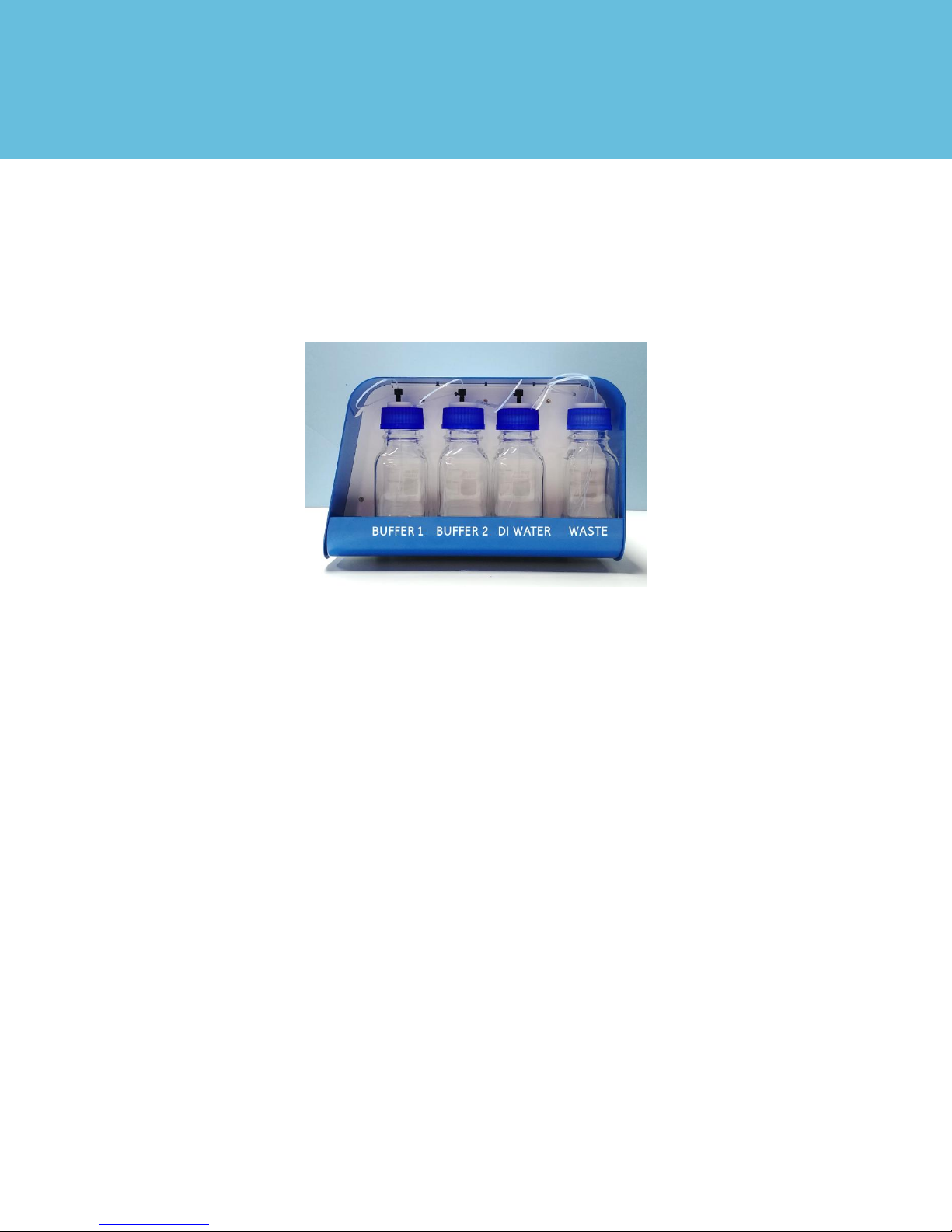
59
OpenSPR 1-Channel Operation Manual V4.1.01
4 SYSTEM DETAILS
4.1 OpenSPR Hardware
The OpenSPR contains optical, microfluidic, thermal and mechanical systems.
The right side of the instrument contains the external fluidic setup [Figure 4.1]. The external
fluidic setup contains 2 buffer bottles, a bottle for DI water, and a waste bottle for the inlets and
outlets of the fluidics respectively.
Figure 4.1 OpenSPR external fluidic setup.
On the front of the instrument, the user will interface with the power button and injection port
[Figure 4.2]. The injection port is used to insert the user sample into the instrument using a
syringe containing a blunt-end injection tip. User sample loaded into the injection port will fill a
sample loop internal to the instrument. The sample overflow will exit into the waste bottle.
Pressing the power button will turn on the OpenSPR when it is connected to a power outlet. The
outer rim of the power button as well as a light underneath the lid will illuminate when powered
on. To power off the OpenSPR, hold the power button down for 10 seconds until the lights of the
OpenSPR turn off.
Page 60
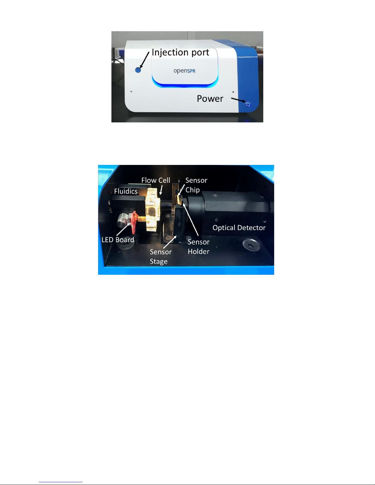
60
OpenSPR 1-Channel Operation Manual V4.1.01
Figure 4.2 OpenSPR injection port and power button.
Opening the lid of the OpenSPR box will expose the optics system, as well as the fluidics system
which interfaces with the sensor chip [Figure 4.3].
Figure 4.3 Optical and fluidic system which interfaces with the sensor chip.
The fluidics in the OpenSPR interfaces with the sensor through the flow cell. The flow cell is
composed of a PDMS material containing 2 microfluidic channels. The sensor chip will seal against
the flow cell, allowing flow to pass through to the outlet waste. The sealing of the sensor is
controlled through a motorized sensor stage. The docking and undocking of the stage can be
controlled using the OpenSPR software.
The optics system composes an LED light source, which transmits light through the flow cell and
sensor into the optical detector.
Page 61

61
OpenSPR 1-Channel Operation Manual V4.1.01
 Loading...