

Nicotra RHM 31/F1, RDA 21, RVM F1, RDM 3E/FE 4D/43/64, RDM 3E/FE BI/4P/6P Operating Instructions Manual
...
Betriebsanleitung DE
Dachventilatoren
(Original)
Operating Instructions EN
Roof extract fans
(Translation of the original)
BA-REF 5.9 - 12/2015
RHM
FDM
RVM
RDA
RDM 3E / FE

BA-REF 5.9 - 12/2015 Deutsch
Inhaltsverzeichnis
1. Revisionsindex ............................................................................................................................................ 2
2. Zu dieser Betriebsanleitung ........................................................................................................................ 3
3. Bestimmungsgemäße Verwendung ............................................................................................................ 5
4. Sicherheit .................................................................................................................................................... 6
5. Produktbeschreibung .................................................................................................................................. 9
6. Transport und Lagerung ............................................................................................................................ 11
7. Montage..................................................................................................................................................... 12
8. Elektrischer Anschluss .............................................................................................................................. 14
9. Inbetriebnahme / Bedienung ..................................................................................................................... 16
10. Instandhaltung ........................................................................................................................................... 17
11. Störungen .................................................................................................................................................. 18
12. Service, Ersatzteile und Zubehör .............................................................................................................. 19
13. Anhang ...................................................................................................................................................... 20
EG-KONFORMITÄTSERKLÄRUNG ................................................................................................................ 21
EG-KONFORMITÄTSERKLÄRUNG ................................................................................................................ 22
EG-KONFORMITÄTSERKLÄRUNG ................................................................................................................ 23
English EN-2…. EN-22
Weitere Sprachen auf Anfrage / Further languages on request
1. Revisionsindex
Tabelle 1-1: Revisionsindex
Revision Datum
BA-DV 5.1 – 05/2006 05/2006
BA-DV 5.2 – 03/2009 03/2009
BA-DV 5.3 – 11/2009 11/2009
BA-DV 5.4 – 07/2010 07/2010
BA-DV 5.5 – 01/2011 01/2011
BA-REF 5.6 – 07/2013 07/2013
BA-REF 5.7 – 02/2014 02/2014
BA-REF 5.8 – 05/2014 05/2014
BA-REF 5.9 – 12/2015 12/2015
DE-2/24
BA-REF 5.9 - 12/2015 Deutsch
2. Zu dieser Betriebsanleitung
Diese Betriebsanleitung ist Teil des Dachventilators.
Für Schäden und Folgeschäden, die durch Nichtbeachtung der
Betriebsanleitung entstehen, übernimmt die Nicotra Gebhardt GmbH
keinerlei Haftung oder Gewährleistung.
Betriebsanleitung vor Gebrauch aufmerksam lesen.
Betriebsanleitung während der Lebensdauer des Dachventilators
aufbewahren.
Betriebsanleitung dem Personal jederzeit zugänglich machen.
Betriebsanleitung an jeden nachfolgenden Besitzer oder Benutzer des
Dachventilators weitergeben.
Jede vom Hersteller erhaltene Ergänzung in die Betriebsanleitung
einfügen.
2.1. Gültigkeit
Diese Betriebsanleitung ist nur gültig für die auf der Titelseite
angegebenen Dachventilatoren.
2.2. Zielgruppe
Zielgruppe dieser Betriebsanleitung sind Betreiber und ausgebildetes
Fachpersonal, das mit Montage, Inbetriebnahme, Bedienung,
Instandhaltung und Außerbetriebnahme vertraut ist.
2.3. Mitgeltende Dokumente
Folgende Dokumente und Angaben auf dem Dachventilator zusätzlich
zur Betriebsanleitung beachten:
- IEC 60364/
- DIN VDE 0100
- DIN EN 60204-1
- DIN EN ISO 13857
- DIN EN ISO 12100-1; -2
- DIN EN ISO 13732-1
- Typenschild
- Technischer Katalog
- Zusätzliche Hinweise auf dem
Gerät (Warnhinweise,
Drehrichtungspfeile)
2.4. Symbole und Kennzeichnungen
2.4.1. Aufbau von Warnhinweisen
Signalwort
Art, Quelle und Folgen der Gefahr!
Maßnahme zur Vermeidung der Gefahr
DE-3/24

BA-REF 5.9 - 12/2015 Deutsch
2.4.2.
Gefahrenstufen in Warnhinweisen
Tabelle 2-1: Gefahrenstufen in Warnhinweisen
Symbol / Gefahrenstufe Eintretens-
Folgen bei Nichtbeachtung
Wahrscheinlichkeit
Unmittelbar drohende
Gefahr
Tod, schwere Körperverletzung
GEFAHR
Mögliche drohende Gefahr Tod, schwere Körperverletzung
WARNUNG
Mögliche drohende Gefahr Leichte Körperverletzung
VORSICHT
VORSICHT
Mögliche drohende Gefahr Sachschaden
2.4.3. Hinweise
Hinweis Hinweis zum leichteren bzw. sicheren Arbeiten.
Maßnahme zum leichteren bzw. sicheren Arbeiten.
2.4.4. Sonstige Symbole und Kennzeichnungen
Tabelle 2-2: Sonstige Symbole und Kennzeichnungen
Symbol Bedeutung
DE-4/24
Voraussetzung zu einer Handlung
Handlung mit einem Schritt
1. ….
2. ….
Handlung mit mehreren Schritten
3. ….
앫
-
Hervorhebung (fett) Hervorhebung
Aufzählung (erste Ebene)
Aufzählung (zweite Ebene)

BA-REF 5.9 - 12/2015 Deutsch
3. Bestimmungsgemäße Verwendung
3.1. Betriebsdaten / Grenzdaten
Verletzungsgefahr!
Technische Daten und zulässige Grenzwerte einhalten.
WARNUNG
VORSICHT Als nicht bestimmungsgemäße Verwendung gilt z.B. die Förderung:
VORSICHT Unerlaubte Betriebszustände:
VORSICHT Dynamische Beanspruchung des Laufrades vermeiden.
Die Technischen Daten sind dem Typenschild, dem technischen
Datenblatt und dem technischen Katalog zu entnehmen!
Die Dachventilatoren sind zur Absaugung staubfreier Luft und sonstigen,
nicht aggressiven Gasen oder Dämpfen geeignet.
Zulässige Fördermediumstemperaturen
Tabelle 3-1: Grenzdaten
Baureihe
RHM 31/F1 -20°C bis +40°C
RDA 21 -20°C bis +40°C 1)
FDM F1 -20°C bis +40°C
RVM F1 -20°C bis +40°C
RDM 3E/FE - 4D/43/63 -20°C bis +120°C
RDM 3E/FE - BI/4P/6P -20°C bis +60°C
1)
= Daten je Typ siehe Komplettkatalog „Die Dachventilatoren“.
zul. Temperatur des
Fördermediums
max. Umgebungstemperatur am
Antriebsmotor
+ 40°C
von Medien mit unerlaubten hohen oder niedrigen Temperaturen
von aggressiven Medien
von stark staubhaltigen Medien
von explosionsgefährdeten Medien
Kein Betrieb über der angegebenen Drehzahl (Typenschild, techn. Daten)
Kein Betrieb in Drehzahlbereichen erhöhter Schwingungen (Resonanz)
Kein Betrieb in Drehzahlbereichen außerhalb des zulässigen
Kennfeldbereiches (Strömungsstabilität)
Kein Betrieb bei Verschmutzung des Ventilators
Keine häufigen Lastwechsel!
DE-5/24

BA-REF 5.9 - 12/2015 Deutsch
4. Sicherheit
4.1. Produktsicherheit
Die Ventilatoren bieten ein hohes Maß an Betriebssicherheit und einen
hohen Qualitätsstandard, der durch ein zertifiziertes QualitätsmanagementSystem (EN ISO 9001) gewährleistet wird.
Alle Ventilatoren werden vor Verlassen des Werkes einer Kontrolle
unterzogen und mit einem Prüfsiegel versehen. Dennoch können beim
Betrieb von Dachventilatoren der Nicotra Gebhardt GmbH Gefahren für Leib
und Leben des Benutzers oder Dritter bzw. Beeinträchtigungen des
Dachventilators und anderer Sachwerte entstehen.
Dachventilator nur in technisch einwandfreiem Zustand sowie
bestimmungsgemäß, sicherheits- und gefahrenbewusst unter Beachtung
der Betriebsanleitung benutzen.
Störungen, die die Sicherheit beeinträchtigen können, umgehend
beseitigen lassen.
Dachventilatoren werden ohne saugseitigen Berührungsschutz
geliefert. Besteht durch die Art des Einbaus die Gefahr einer Berührung
des Laufrades, so ist eintrittsseitig ein Schutzgitter entsprechend
GEFAHR
DIN EN ISO 13857 (als Zubehör erhältlich) anzubringen.
Erst dann darf der Dachventilator in Betrieb gesetzt werden!
4.2. Sicherheitsvorschriften
Dachventilator nur in Übereinstimmung mit folgenden Vorschriften in
Betrieb nehmen, betreiben und instand halten:
− Betriebsanleitung
− Warn- und Hinweisschilder am Dachventilator
− Alle anderen zur Anlage gehörenden Betriebs- und
Montageanleitungen
− Anlagenspezifische Bestimmungen und Erfordernisse
− Gültige nationale und regionale Vorschriften, insbesondere Sicherheit,
Unfallverhütung
4.3. Schutzeinrichtungen
Rotierende Teile (Wellen, Laufrad usw.) durch geeignete
Schutzeinrichtungen gegen Berührung sichern.
Schutzvorrichtungen, die bei der Montage demontiert wurden, un-
VORSICHT Die Eignung der Schutzeinrichtungen und deren Befestigungen am
mittelbar nach der Montage (und vor dem elektrischen Anschluss) wieder
anbringen.
Ventilator sind im Zusammenhang mit dem gesamten
Sicherheitskonzept der Anlage zu bewerten.
DE-6/24

BA-REF 5.9 - 12/2015 Deutsch
4.4. Qualifikation des Personals
Sicherstellen, dass die Montage und alle Arbeiten am Dachventilator nur
von Fachmonteuren unter Beachtung dieser Betriebsanleitung sowie den
gültigen Vorschriften ausgeführt werden.
Elektroanschluss nur durch ausgebildete Elektro-Fachkraft ausführen.
4.5. Schutzausrüstung
Sicherstellen, dass das Personal je nach Einsatz und
Umgebungsbedingung geeignete Schutzausrüstung trägt.
WARNUNG
Die Schutzkleidung ist in den folgenden Abschnitten beschrieben!
4.6.
4.6.1. Geräuschemission
4.6.2. Hohe Lasten
4.6.3. Rotierende Wellen und Laufräder
Besondere Gefahren
Die zu erwartende Schallemission für den bestimmungsgemäßem Betrieb
des Ventilators ist in den technischen Katalogen dokumentiert und
entsprechend zu berücksichtigen.
Gehörschutz tragen bei Arbeiten in der Nähe - oder am laufenden
Ventilator!
Aufgrund des hohen Gewichts des Dachventilators und seiner Komponenten
ergeben sich bei Transport und Montage folgende Gefahren:
Klemm-, Quetsch- und Schneidgefahren durch Bewegen oder Kippen
Gefahren durch Herabfallen von Komponenten
Nicht unter schwebenden Lasten aufhalten oder arbeiten.
Schutzhelm, Sicherheitsschuhe und Handschuhe tragen.
Auf rotierende Wellen und Laufräder fallende Gegenstände können
wegfliegen und schwere Verletzungen verursachen.
Kleidungsstücke oder Haare können sich an rotierenden Wellen und in
Laufrädern verfangen.
Schutzvorrichtungen während des Betriebs nicht entfernen.
Eng anliegende Kleidung tragen.
Bei Arbeiten in der Nähe rotierender Wellen und Laufräder
Schutzbrille tragen.
Achtung Stromschlag!
Elektrische Spannung im Zwischenkreis der Steuerelektronik und an
den Netzanschlüssen beim Drehen des Permanentmagnet-Motors!
keine Arbeiten am Ventilator durchführen bei frei drehendem Laufrad/
Motor
Laufrad mit geeigneten Mitteln arretieren
DE-7/24

BA-REF 5.9 - 12/2015 Deutsch
4.6.4. Heiße Oberflächen
Im Betrieb besteht Verbrennungs- und Verbrühungsgefahr aufgrund heißer
Oberflächen.
Motor während des Betriebs nicht berühren.
Bei Stillstand des Dachventilators warten, bis sich der Motor
abgekühlt hat.
Schutzhandschuhe tragen
4.7. Bauliche Veränderungen, Ersatzteile
Hinweis Eigenmächtige bauliche Veränderungen am Dachventilator sind ohne
Zustimmung der Nicotra Gebhardt GmbH nicht zulässig. Für daraus
entstandene Schäden übernimmt die Nicotra Gebhardt GmbH keine
Haftung. Es dürfen nur Original-Ersatzteile der Nicotra Gebhardt GmbH
verwendet werden.
4.8. Installation und Instandhaltung
Vor Arbeiten am Dachventilator folgende Maßnahmen durchführen:
- Anlage abschalten und gegen unbeabsichtigtes Wiedereinschalten
sichern.
- Schild mit folgendem Text anbringen:
Nicht einschalten! An der Anlage wird gearbeitet.
Bild 4-1:
Typenschild-Muster
4.9. Schilder auf dem Dachventilator
Typenschild und Drehrichtungspfeil sind je nach Baureihe gut sichtbar am
Gehäuse bzw. am Tragbügel angebracht.
4.9.1. Typenschild
DE-8/24

BA-REF 5.9 - 12/2015 Deutsch
4.9.2 Drehrichtungspfeil
Bild 4-2:
Drehrichtungspfeil
4.9.3 Klemmbrett-Schaltbild
Bild 4-3:
Schaltbild-Muster
In Klemmenkasten eingeklebt / eingelegt bzw. an Motorträger
aufgeklebt.
Nur Muster!
5. Produktbeschreibung
5.1. Dachventilatoren allgemein
Alle Dachventilatoren werden anschlussfertig geliefert und sind auf der
Austrittseite mit einem Berührungsschutzgitter entsprechend
DIN EN ISO 13857 abgesichert.
Die Eintrittsseite ist serienmäßig ohne Schutzgitter.
GEFAHR
Besteht durch die Art des Einbaus die Gefahr einer Berührung des
Laufrades, so ist eintrittsseitig ein Schutzgitter entsprechend
DIN EN ISO 13857 (als Zubehör erhältlich) anzubringen.
5.2.
Dachventilatoren mit Einbaumotor
5.2.1. RDA 21 genovent
Radial-Dachventilator, mit Einbaumotor, horizontal ausblasend, aus
verzinktem Stahlblech gefertigt.
Austrittsseitig mit Berührungsschutzgitter nach DIN EN ISO 13857.
5.3. Dachventilatoren mit Anbaumotor
5.3.1. RVM F1
Radial-Dachventilator, vertikal ausblasend, mit IEC-Normmotor, V-Gehäuse
und tragende Konstruktion aus verzinktem Stahlblech gefertigt.
Austrittsseitig mit Berührungsschutzgitter nach DIN EN ISO 13857.
5.3.2. RDM 3E/FE genovent
Radial-Dachventilator, vertikal ausblasend, mit IEC-Normmotor außerhalb
des Förderstromes mit Außenluftkühlung. Gehäuse aus Aluminium und
tragende Konstruktion aus verzinktem Stahlblech gefertigt.
Weiterführende Informationen zu Geräten mit integrierter Drehzahlregelung
siehe gesonderte Betriebsanleitung BA-ESR_NI-DV.
DE-9/24

BA-REF 5.9 - 12/2015 Deutsch
5.3.3. RHM 31/F1
Radial-Dachventilator, horizontal ausblasend, mit IEC-Normmotor, Haube
und tragende Konstruktion aus verzinktem Stahlblech gefertigt.
Austrittsseitig mit Berührungsschutzgitter nach DIN EN ISO 13857.
5.3.4. FDM F1
Radial-Dachventilator, in extrem schallgedämmter Ausführung, vertikal
ausblasend, mit IEC-Normmotor, Gehäuse und tragende Konstruktion aus
verzinktem Stahlblech gefertigt.
Austrittsseitig mit Berührungsschutzgitter nach DIN EN ISO 13857.
5.4. Motorschutz
5.4.1. Baureihen RDA 21
Motoren der Baureihen RDA 21 sind mit Thermokontakten ausgerüstet.
Bei Einphasen-Wechselstrom-Motoren bis zur max. Stromaufnahme von
2,5 A sind die Thermokontakte extern in Reihe mit der Wicklung gelegt.
Sie schalten den Motor bei Erreichen einer Grenztemperatur ab und nach
dem Abkühlen selbsttätig wieder ein. Bei allen übrigen Motoren erfolgt die
Überwachung der Wicklungstemperatur über Thermokontakte, zusammen
mit einem Motorvollschutzschaltgerät oder einer Schützkombination.
5.4.2. Baureihen RVM/ RDM3E/ RDMFE/ RHM/ FDM
Motoren der Baureihen RVM/ RHM/ FDM/ RDM 3E/FE - 4D/43/63 sind
standardmäßig mit Kaltleiter-Temperaturfühlern ausgerüstet.
Die Kaltleiter schützen in Verbindung mit einem Kaltleiter-Auslösegerät den
Motor vor Überlastung.
Geräte mit integrierter Drehzahlregelung, z.B. RDM 3E/FE - BI/4P/6P werden
durch den Frequenzumrichter vor Überlast geschützt. Der Frequenzumrichter
reagiert bei Überlast mit einer Drehzahlreduktion bis hin zum Ausschalten.
DE-10/24

BA-REF 5.9 - 12/2015 Deutsch
6. Transport und Lagerung
6.1. Verpackung
Dachventilatoren werden abhängig von Baugröße und Gewicht in stabilen
Kartonagen oder Holzverschlägen verpackt.
6.2. Symbole auf der Verpackung
Auf den Kartonagen sind folgende Symbole angebracht:
Tabelle 6-1: Symbole auf der Verpackung
WARNUNG
VORSICHT Beschädigung des Gehäuses beim Anhängen!
Bild 6-1:
Anhängevorrichtung
Symbol:
Bedeutung: Zerbrechliches Gut Vor Nässe schützen Oben
6.3. Dachventilator transportieren
Verletzungsgefahr durch herabfallende Komponenten!
Nur geprüfte und geeignete Lastaufnahmemittel (siehe Typenschild bzw.
Datenblatt) verwenden.
Dachventilator nur am Grundrahmen und/oder an den Ringösen anhängen.
Ladung sichern.
Nicht unter schwebenden Lasten aufhalten.
Unten aufgeführte Dachventilatoren immer mit Anhängevorrichtung und
Abstandstraverse an den Ringösen anhängen.
Anhängevorrichtung und Abstandstraverse für Dachventilator:
RVM F1-7180 und 7190
RDM FE-7180 und 7190
1. Transportmittel entsprechend dem Ventilatorgewicht und den
Abmessungen auswählen.
2. Dachventilator an den dafür vorgesehenen Anhängepunkten anhängen
3. Ladung z. B. durch Transportgurte oder Rutschsicherungen sichern.
4. Dachventilator sorgfältig transportieren und Schäden z. B. durch Stöße
und hartes, verkantetes Aufsetzen vermeiden.
6.4. Dachventilator lagern
VORSICHT Korrosion
Dachventilator in Verpackung einlagern bzw. diese in Abhängigkeit von
den äußeren Einflüssen ergänzen.
Dachventilator nur in einem gut durchlüfteten Raum unter normalen
Temperaturverhältnissen und in einer nicht korrosiven Atmosphäre
lagern.
Dachventilator bei Luftfeuchtigkeit unter 70 % lagern.
Max. zulässige Temperatur von –20 °C bis +40 °C einhalten.
DE-11/24

BA-REF 5.9 - 12/2015 Deutsch
7. Montage
7.1. Sicherheitshinweise zur Montage
Sicherheitshinweise und Schutzmaßnahmen in Kapitel 4 sowie die
gültigen gesetzlichen Vorschriften beachten.
7.2. Montage vorbereiten
Der Aufstellungsort ist in Art, Beschaffenheit, Umgebungstemperatur
und Umgebungsmedium für den jeweiligen Dachventilator geeignet.
Die Unterkonstruktion ist eben und ausreichend tragfähig.
Der Aufstellungsort ist horizontal (Montage auf Flächen mit
Neigungen bis max. 20° Neigungswinkel ist zulässig).
Hinweis Bei unten aufgeführten Dachventilatoren beide gegenüberliegende
Austrittsöffnungen quer zur Neigung anordnen.
RDA 21;
RDM 3E/FE
Richtig Falsch
Bild 7-1:
Montagerichtung
Dachventilator vorsichtig auspacken.
Verpackungsmaterial vollständig entfernen und fachgerecht
entsorgen.
DE-12/24

BA-REF 5.9 - 12/2015 Deutsch
7.3. Montage durchführen
Die Dachventilatoren sind für Sockelmontage konzipiert.
Für die Befestigung am Dachsockel sind im Grundrahmen vier Bohrungen
enthalten.
Zugang zu den Befestigungsbohrungen:
RDA 21
RHM
Haube (7) entfernen
FDM
Außenmantel-Befestigungsschrauben lösen und
Außenmantel (6) abnehmen oder anheben und sichern.
RDM 3E /FE
RVM F1
Bild 7-2: Dachsockel
Bild 7-3: Abdichtung
Hinweis Für Kanalanschluss flexible Anschlussstutzen verwenden!
5
Seitenteile (5) abnehmen
Seitenteile (5) abnehmen
Haube (7) und Schutzgitter (8)
entfernen
A Gebhardt-Dachsockel ZBS (Zubehör)
1 Dichtungslippe (Lieferumfang-Dachsockel ZBS)
B Mauersockel (bauseits)
2 Dichtungsmaterial (bauseits)
3 Distanzscheibe (bauseits)
1. Dichtungslippe (1) bzw. Dichtungsband (2) auf die Sockelfläche auflegen
(für luftdichte Auflage).
2. Dachventilator mit der Grundplatte auf den Sockel (A bzw. B) setzen
3. Anschlusskabel einziehen, nicht anschließen.
4. Dichtungsscheiben (4) (Kunststoff) unter die SockelBefestigungsschrauben montieren.
5. Sockelschrauben gleichmäßig festdrehen.
6. Laufrad von Hand drehen und sicherstellen, dass es leicht läuft und nicht
streift.
7. Wenn erforderlich Ventilator Seitenteile, Schutzgitter und Haube wieder
anbauen.
Von Anlagenteilen werden keine Kräfte oder Schwingungen auf den
Dachventilator übertragen!
Ventilator auf Standsicherheit geprüft (kein Kippen möglich)!
DE-13/24

BA-REF 5.9 - 12/2015 Deutsch
VORSICHT Anstreifen des Laufrades und Ermüdungsbruch durch Verspannungen!
Ungleichmäßiges Festdrehen der Sockelschrauben vermeiden.
Dachventilator so montieren, dass die Standsicherheit bei Betrieb
jederzeit gewährleistet ist.
7.4. Schutzvorrichtungen montieren
Hinweis Die Einhaltung der DIN EN ISO 13857 bezieht sich nur auf den montierten
Berührungsschutz, sofern dieser zum Lieferumfang gehört.
Für die vollständige Erfüllung der DIN EN ISO 13857 ist der Betreiber der
Anlage verantwortlich.
1. Frei zugängliche Eintrittsöffnungen mit Schutzvorrichtungen
(DIN EN ISO 13857) sichern.
2. Schutzvorrichtungen so auslegen, dass sie das Ansaugen oder
Hineinfallen von Gegenständen verhindern.
3. Sicherstellen, dass alle mechanischen Schutzeinrichtungen angebracht
sind.
8. Elektrischer Anschluss
8.1. Sicherheitshinweise zum elektrischen Anschluss
Achtung, Gefahr durch Stromschlag!
Sicherheitshinweise und Schutzmaßnahmen in Kapitel 4 sowie die
GEFAHR
8.2. Motor anschließen
Hinweis Alle Dachventilatoren werden anschlussfertig geliefert. Der Klemmenkasten
Hinweis Für die Einhaltung der gültigen EMV Normen und Richtlinien ist stets das
VORSICHT
Bei der Kombination von Revisionsschalter mit externem Frequenzumrichter
Stromart, Spannung und Frequenz des Netzanschlusses auf
gültigen gesetzlichen Vorschriften beachten.
EN 60204
bzw. Revisionsschalter befindet sich unter der Haube bzw. unter dem
Gehäusedeckel.
Das Anschluss-Schaltbild befindet sich im Klemmenkasten/ integriertem FU/
REP-Schalter.
Gesamtsystem in der konkreten Anwendung zu bewerten.
Dies liegt in der Verantwortung des Kunden.
Frequenzumrichterbetrieb
Dachventilatoren der Baureihen RDA 21 nur unter Verwendung
angepasster, allpolig wirksamer Sinusfilter zwischen Umrichter und Motor
betreiben.
Einfache dU/dt-Filter sind für den Betrieb am Umrichter nicht zulässig.
sind gegebenenfalls gesonderte EMV-Schutzmaßnahmen erforderlich.
Übereinstimmung zum Ventilator- bzw. Motortypenschild geprüft
Bei Motoren mit Nennleistung >4 kW Stern-Dreieck-Anlauf oder
Sanftanlauf vorsehen
DE-14/24

BA-REF 5.9 - 12/2015 Deutsch
Ggf. Revisionsschalter vorhanden
Gesonderte Betriebsanleitung BA-ESR_NI-DV für Geräte mit
integriertem Frequenzumrichter beachten
Tabelle 8-1:
Übersicht Dachventilatoren
1 Regenschutzhaube
2 Kabeldurchführung
3 Klemmenkasten
4 Revisionsschalter
(optional)
5 Seitenteil
6 Außenkulisse
7 Gehäuse
8 Schutzgitter
9 Integrierter
Frequenzumrichter bei
RDM 3E/FE - BI/4P/6P
5
RHM
FDM
1234
RDA 21
RDM 3E / FE
RVM F1
1. Regenschutzhaube (1) demontieren.
1.1 . Schutzgitter demontieren (RVM und FDM) (8)
2. Bei hocheffizienten PM-Antrieben ist das Laufrad zu arretieren
Der Dachventilator ist gegen unerwarteten Anlauf geschützt.
3. Seitenteile demontieren bei folgenden Baureihen
3.1. Baureihe FDM - Außenkulisse (6) lösen und abheben bzw. anheben und sicher unterbauen
3.2. Baureihen RDA 21/ RDM 3E/RDM FE Seitenteil (5) demontieren
3.3. RVM: Gehäuse (7) ggf. lösen bzw. anheben und sicher unterbauen (große Baugrößen)
4. Anschlusskabel durch die Kabeldurchführung im Grundrahmen (2) zum Klemmenkasten (3) bzw.
Revisionsschalter (4) oder Frequenzumrichter (9) führen.
5. Die Netzzuleitung bei RDM 3E/RDM FE locker verlegen damit dass Mittelteil leicht zurückgeklappt
werden kann.
6. Kabel im Bereich des Laufrades mit Kabelclips an der Stütze fixieren (RDM 3E/RDM FE), bzw. mit
Kabelbinder an Schutzgitter und/oder Tragbügel fixieren.
7. Abgenommene Außenkulisse (FDM) bzw. Seitenteile (RDA 21/ RDM 3E/RDM FE) bzw. Gehäuse
(RVM) wieder montieren.
8. Motor nach beigefügtem Anschlussschema anschließen bzw. am integrierten Frequenzumrichter
(siehe gesonderte Betriebsanleitung BA-ESR_NI-DV)
9. Haube (1) und Schutzgitter (RVM und FDM) (8) montieren.
10. Sicherstellen, dass alle elektrischen Schutzeinrichtungen angebracht und angeschlossen sind.
11. Motoren mit Nennleistung >4 kW an Stern-Dreieck-Anlauf oder Sanftanlauf anschließen.
DE-15/24

BA-REF 5.9 - 12/2015 Deutsch
8.3. Probelauf durchführen
Verletzungsgefahr durch rotierendes Laufrad!
Bei geöffnetem Ventilator nie in das Laufrad greifen.
GEFAHR
1. Motor / Frequenzumrichter vom Netz trennen.
2. Dachventilator gegen unbeabsichtigtes Einschalten sichern.
3. Alle Fremdkörper (Werkzeuge, Kleinteile, Bauschutt etc.) aus dem
Kanalsystem und dem Ventilator entfernen.
4. Alle Revisionsöffnungen schließen.
5. Ventilator einschalten und die Drehrichtung des Laufrades durch
Vergleich mit dem Drehrichtungspfeil am Ventilator prüfen.
6. Bei falscher Drehrichtung den Motor / Frequenzumrichter unter
Beachtung der Sicherheitsvorschriften elektrisch umpolen oder über das
OJ-DV Hterm im Menüpunkt: Setup/Rotation (vgl. Seite 33 in der
separaten Betriebsanleitung BA-ESR_NI-DV).
7. Nach Erreichen der Betriebsdrehzahl die Stromaufnahme messen und
mit dem Motornennstrom auf dem Dachventilator- bzw. Motortypenschild
vergleichen.
8. Bei anhaltendem Überstrom Dachventilator sofort abschalten.
9. Dachventilator auf ruhigen Lauf prüfen. Sicherstellen, dass keine
außergewöhnlichen Schwingungen und Vibrationen auftreten.
10. Motor auf untypische Geräusche prüfen.
9. Inbetriebnahme / Bedienung
Die Motoren sind für Dauerbetrieb S1 ausgelegt. Bei mehr als drei Anläufen
pro Stunde ist die Eignung des Motors von der Nicotra Gebhardt GmbH zu
bestätigen.
9.1. Dachventilator in Betrieb nehmen
Verletzungsgefahr durch rotierende Teile und heiße Oberflächen!
Sicherstellen, dass alle Schutzvorrichtungen angebracht sind!
Sicherstellen, dass das Laufrad entsprechend DIN EN ISO 13857
GEFAHR
VORSICHT Sachschaden durch falschen Sinusfilter
VORSICHT Sachschaden durch Netzüberlastung bei überhöhten Anlaufströmen!
abgesichert ist!
Dachventilatoren der Baureihen RDA 21 mit Frequenzumrichter nur mit
angepasstem, allpolig wirkendem Sinusfilter betreiben.
Leistungsbegrenzung des Energieversorgungsunternehmens beachten.
Aktion
1. Funktion aller angeschlossenen Regelorgane prüfen.
2. Dachventilator einschalten.
DE-16/24

BA-REF 5.9 - 12/2015 Deutsch
10. Instandhaltung
10.1. Sicherheitshinweise zur Instandhaltung
Sicherheitshinweise und Schutzmaßnahmen in Kapitel 4 sowie die
gültigen gesetzlichen Vorschriften beachten.
Die Vorschriften des Motorherstellers sowie Angaben der Hersteller der
Schalt- und Steuergeräte beachten
10.2. Instandhaltung vorbereiten
1. Motor vom Netz trennen.
2. Bei Dachventilator mit Revisionsschalter, Motor mit Revisionsschalter
abschalten.
3. Dachventilator gegen unbeabsichtigtes Einschalten sichern.
4. Warten, bis das Laufrad steht.
5. Warten, bis alle heißen Oberflächen kalt sind.
6. Alle Reststoffe im Ventilator entfernen.
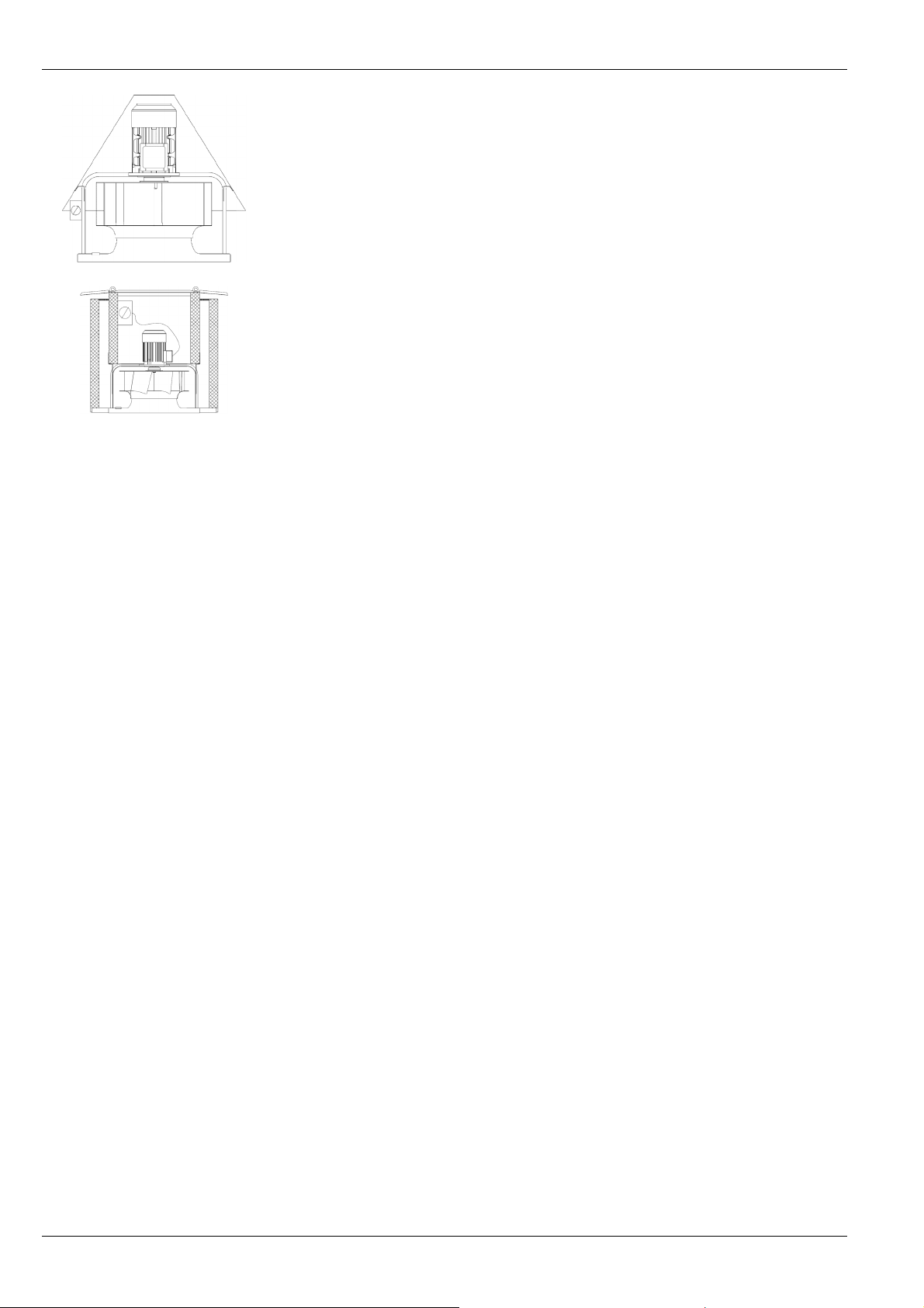
10.3. Dachventilator RDM 3E/RDM FE hochklappen /
GEFAHR
Bild 10-1: Klappmechanik
zurückklappen
Verletzungsgefahr durch unbeabsichtigtes Zurückklappen des
Dachventilators!
Dachventilator gegen Zurückklappen sichern.
Hochklappen
Seitenteile sind abgenommen; Deckel demontiert
10
9
8
1. Schrauben (8) entfernen.
2. Mittelteil (10) hochklappen.
3. Mittelteil mit Schrauben (8) und Muttern im Kippgelenk (9) beidseitig
sichern.
Zurückklappen ( nach erfolgter Wartung)
1. gekippten Dachventilator unterbauen (Sicherungsschrauben
entlasten).
2. Sicherungsschrauben im Kippgelenk (9)entfernen und Dachventilator
vorsichtig zurückschwenken.
3. Befestigungsschrauben (8) einsetzen und festziehen.
DE-17/24

BA-REF 5.9 - 12/2015 Deutsch
10.4. Regelmäßige Kontrollintervalle durchführen
Zur Aufrechterhaltung des Betriebes und der Sicherheit, empfehlen wir die
Ventilatoren in regelmäßigen Abständen auf ihre Funktion und
Beschaffenheit von fachlich qualifiziertem Personal oder einer Fachfirma
prüfen zu lassen und dies zu dokumentieren.
Art, Umfang und Wartungsintervalle, sowie darüber hinaus erforderliche
Tätigkeiten sind in Abhängigkeit des Einsatzes der Ventilatoren sowie der vor
Ort vorherrschenden Bedingungen festzulegen.
Die Wartungs- und Prüfungsempfehlung in Anlehnung an die VDMA 24186-1
finden Sie auf unserer Internetseite unter „Downloads“.
Instandhaltung vorbereitet
Dachventilator hochgeklappt und gesichert (RDM 3E/RDM FE)
VORSICHT Sachschaden durch Hochdruckreiniger!
Keine Hochdruckreiniger (Dampfstrahlreiniger) zum Reinigen
verwenden.
Wartungsempfehlung für Dachventilatoren:
Ggf. Probelauf durchführen (siehe Kapitel 8.3.).
Durchgeführte Kontrollintervalle dokumentieren.
VORSICHT Lässt der Zustand des Ventilators eine Instandsetzung durch geeignete
Maßnahmen nicht mehr zu, ist der Ventilator unverzüglich außer
Betrieb zu setzen und ggf. zu erneuern.
11. Störungen
VORSICHT Beschädigung des Dachventilators durch unzulässige
Treten während des Betriebs Störungen auf, die nicht vom Wartungspersonal behoben werden können, bitte Kontakt mit der Service-Abteilung
der Nicotra Gebhardt GmbH aufnehmen.
Betriebszustände!
Bei Überschreitung der zulässigen Werte, Unregelmäßigkeiten oder
Störungen Dachventilator sofort abschalten.
DE-18/24

BA-REF 5.9 - 12/2015 Deutsch
12. Service, Ersatzteile und Zubehör
Nicotra Gebhardt GmbH
Gebhardtstraße 19–25
74638 Waldenburg
Germany
12.1. Ersatzteile bestellen
Nur Original-Ersatzteile der Nicotra Gebhardt GmbH entsprechend der
Ersatzteilliste verwenden.
Der Einbau von Ersatzteilen anderer Hersteller kann die Sicherheit
beinträchtigen.
Beim Einbau von Ersatzteilen anderer Hersteller erlischt die CE-Konformität.
Für Schäden und Folgeschäden, die durch Verwendung von Ersatzteilen
anderer Hersteller entstehen, übernimmt die Nicotra Gebhardt GmbH
keinerlei Haftung oder Gewährleistung.
Ersatzteile online bestellen - www.gebhardt.de/Partshop
Telefon: +49 (0) 7942 101 384
Telefax: +49 (0) 7942 101 385
Mail: service@nicotra-gebhardt.com
www.nicotra-gebhardt.com
12.2. Zubehör
Die Nicotra Gebhardt GmbH bietet ein breites Zubehörprogramm zum
wirtschaftlichen Einsatz der Ventilatoren.
Das Zubehör ist optional und immer separat zu bestellen.
Die Auswahl erfolgt über die technische Dokumentation oder unser
elektronisches Auswahlprogramm.
Für die Montage bzw. Anwendung ist das Zubehör, soweit nicht
selbsterklärend, mit separaten Bedien- oder Montagehinweisen versehen.
DE-19/24

BA-REF 5.9 - 12/2015 Deutsch
13. Anhang
13.1. Weitere Dokumentation der Nicotra Gebhardt GmbH
Tabelle 14 1: Weitere Dokumentation
Art der Dokumentation Wo abgelegt
Wartungs- und Prüfempfehlungen Internet, siehe Link Kapitel 10.4.
Elektrischer Anschlussplan Anschluss-Schaltbilder
EG-Konformitätserklärung zur EG-
Maschinenrichtlinie (2006/42/EG)
EG-Konformitätserklärung zur EG-
Niederspannungsrichtlinie
2006/95/EG
EG-Konformitätserklärung zur EG-
Richtlinie umweltgerechte Gestaltung
"Ökodesign"
energieverbrauchsrelevanter
Produkte (2009/125/EG)
EG-Richtlinie Elektromagnetische
Verträglichkeit (2004/108/EG)
Anhang
Anhang
Anhang
Anhang
DE-20/24

BA-REF 5.9 - 12/2015 Deutsch
EG-KONFORMITÄTSERKLÄRUNG
zur EG-Maschinenrichtlinie (2006/42/EG)
EG-Niederspannungsrichtlinie (2006/95/EG)
Hiermit erklären wir, dass die nachfolgend bezeichnete Maschine aufgrund
ihrer Konzipierung und Bauart sowie in der von uns in Verkehr gebrachten
Ausführung den einschlägigen grundlegenden Sicherheits- und
Gesundheitsanforderungen der unten angeführten EG-Richtlinien entspricht.
Bei einer nicht mit uns abgestimmten Änderung der Maschine verliert diese
Erklärung ihre Gültigkeit.
Bezeichnung: Dachventilator
Maschinentyp: RHM / RDM 3E/FE / FDM / RDA 21 / RVM
Baujahr/Typenbezeichnung: siehe Typenschild
Einschlägige EG-Richtlinien:
EG-Maschinenrichtlinie (2006/42/EG)
EG-Niederspannungsrichtlinie (2006/95/EG)
Angewandte, harmonisierte Normen, insbesondere:
DIN EN ISO 12100 , DIN EN ISO 13857, EN 60204-1
Waldenburg, den 18.12.2015
Bevollmächtigte für die Dokumentation: Jeanette von Berg
Produktionsleiter Leiter Forschung & Entwicklung
i.V. I. Stöbe i.V. Dr. J. Anschütz
Die vollständige Liste der angewandten Normen und technischen Spezifikationen siehe
Herstellerdokumentationen.
DE-21/24

BA-REF 5.9 - 12/2015 Deutsch
EG-KONFORMITÄTSERKLÄRUNG
Hiermit erklären wir, dass die nachfolgend aufgeführten Produkte die
spezifischen Ökodesign-Anforderungen der Verordnung (EU) Nr. 1253/2014
der Kommission, gemäß Anhang III Nummer 1, erfüllen.
Bezeichnung:
Maschinentyp:
Gerätenummer:
Baujahr:
Einschlägige EG-Richtlinie:
Waldenburg, den 18.12.2015
Produktionsleiter Leiter Forschung & Entwicklung
Dachventilator
RHM / RDM 3E/FE / FDM / RDA 21-EC / RVM
siehe Typenschild
siehe Typenschild
EG-Richtlinie umweltgerechte Gestaltung
"Ökodesign" energieverbrauchsrelevanter
Produkte (2009/125/EG)
i.V. I. Stöbe i.V. Dr. J. Anschütz
Die vollständige Liste der angewandten Normen und technischen Spezifikationen siehe
Herstellerdokumentationen.
DE-22/24

BA-REF 5.9 - 12/2015 Deutsch
EG-KONFORMITÄTSERKLÄRUNG
zur EG-Richtlinie Elektromagnetische Verträglichkeit (2004/108/EG)
Hiermit erklären wir, dass die nachfolgend bezeichnete Maschine aufgrund
ihrer Konzipierung und Bauart sowie in der von uns in Verkehr gebrachten
Ausführung den einschlägigen grundlegenden Sicherheits- und
Gesundheitsanforderungen der unten aufgeführten EG-Richtlinie entspricht.
Bei einer nicht mit uns abgestimmten Änderung der Maschine verliert diese
Erklärung ihre Gültigkeit.
Bezeichnung:
Dachventilator
Maschinentyp:
RDM 3E/FE
Gerätenummer:
siehe Typenschild
Baujahr:
siehe Typenschild
Einschlägige EG-Richtlinie:
EG-Richtlinie Elektromagnetische Verträglichkeit (2004/108/EG)
Angewandte, harmonisierte Normen, insbesondere:
RDM 3E/FE - BI/4P/4F/6P: DIN EN 60204-1, DIN EN 61800-3
DIN EN 61000-3-12, DIN EN 61000-3-2
Waldenburg, den 02.01.2015
Produktionsleiter Leiter Forschung & Entwicklung
i.V. I. Stöbe i.V. Dr. J. Anschütz
Die vollständige Liste der angewandten Normen und technischen Spezifikationen siehe
Herstellerdokumentationen.
DE-23/24

BA-REF 5.9 - 12/2015 Deutsch
Nicotra Gebhardt GmbH
Gebhardtstrasse 19-25
74638 Waldenburg, Germany
Telefon +49 (0)7942 1010
Telefax +49 (0)7942 101170
E-Mail info@nicotra-gebhardt.com
www.nicotra-gebhardt.com
DE-24/24

Operating Instructions EN
Roof extract fans
(Translation of the original)
BA-REF 5.9 - 12/2015
RHM
FDM
RVM
RDA
RDM 3E / FE

BA-REF 5.9 - 12/2015 English
Contents
1. Revision Index ....................................................................................................................................... EN-2
2. About This Operating Manual ............................................................................................................... EN-3
3. Designated Use ..................................................................................................................................... EN-5
4. Safety .................................................................................................................................................... EN-6
5. Product Description ............................................................................................................................... EN-9
6. Transport and Storage ........................................................................................................................ EN-11
7. Installation ........................................................................................................................................... EN-12
8. Electrical Connection ........................................................................................................................... EN-14
9. Commissioning / Operation ................................................................................................................. EN-16
10. Maintenance ........................................................................................................................................ EN-17
11. Faults ................................................................................................................................................... EN-18
12. Service, Spare Parts and Accessories ................................................................................................ EN-19
13. Annex .................................................................................................................................................. EN-20
EC DECLARATION OF CONFORMITY ..................................................................................................... EN-21
EC DECLARATION OF CONFORMITY ..................................................................................................... EN-22
EC DECLARATION OF CONFORMITY ..................................................................................................... EN-23
German DE-2.... DE-24
Weitere Sprachen auf Anfrage / Further languages on request
1. Revision Index
Table 1-1: Revision index
Revision Date
BA-DV 5.1 – 05/2006 05/2006
BA-DV 5.2 – 03/2009 03/2009
BA-DV 5.3 – 11/2009 11/2009
BA-DV 5.4 – 07/2010 07/2010
BA-DV 5.5 – 01/2011 01/2011
BA-REF 5.6 – 07/2013 07/2013
BA-REF 5.7 – 02/2014 02/2014
BA-REF 5.8 – 05/2014 05/2014
BA-REF 5.9 – 12/2015 12/2015
EN-2/24

BA-REF 5.9 - 12/2015 English
2. About This Operating Manual
These operating instructions are an integral part of the roof fan.
Nicotra Gebhardt GmbH shall not accept any liability or provide any
warranty cover for primary damage or secondary damage arising as a
consequence of disregarding these operating instructions.
Read operating manual carefully before use.
Retain operating manual for entire service life of roof fan.
Keep operating manual accessible to personnel at all times.
Pass operating manual on to any subsequent owner or user of roof
fan.
Insert any supplementary instructions received from the manufacturer
in the operating manual.
2.1. Validity
This operating manual only applies to the roof fans stated on the front
page.
2.2. Target Group
This operating manual is intended for operators and qualified
professionals trained in installation, commissioning, operation,
maintenance and decommissioning.
2.3. Other Applicable Documents
In addition to reading these instructions, due notice should also be
taken of the following documents and specifications on the roof fan:
- IEC 60364/
- DIN VDE 0100
- DIN EN 60204-1
- DIN EN ISO 13857
- DIN EN ISO 12100-1; -2
- DIN EN ISO 13732-1
- Type plate
- Technical catalogue
- Additional notes on roof fan
(Warning Signs, Arrow
Indicating Direction of
Rotation)
2.4. Symbols and Markings
2.4.1. Use of Warning Signs
Signal word
Nature, source and consequences of hazard!
Steps required to avert danger
EN-3/24

BA-REF 5.9 - 12/2015 English
2.4.2. Levels of Danger in Warning Signs
Table 2-1: Levels of danger in warning signs
Symbol / Danger Level Likelihood of Occurrence Consequences of Neglect
DANGER
Potential danger Death, serious physical injury
Imminent danger Death, serious physical injury
WARNING
Potential danger Minor physical injury
CAUTION
CAUTION
Potential danger Damage to property
2.4.3. Notes
Note Note giving pointers for easier or safe work.
Steps required for easier or safe work.
2.4.4. Other Symbols and Markings
Table 2-2: Other symbols and markings
Symbol Meaning
Requirement for an operation
Operation with one step
1. ….
2. ….
3. ….
앫
-
Accentuation (bold) For emphasis
Operation with several steps
Bullet point (primary list)
Bullet point (secondary list)
EN-4/24

BA-REF 5.9 - 12/2015 English
3. Designated Use
3.1. Operating Data / Maximum Ratings
Risk of injury!
Adhere to technical specifications and permissible limits.
CAUTION
CAUTION
CAUTION
CAUTION
For technical specifications reference should be made to the type plate,
technical data sheet and technical catalogue.
The roof fans are suitable for extracting dust-free air and other non-corrosive
gases or vapours.
Permissible conveyed medium temperatures
Table 3-1: Maximum ratings
Range
RHM 31/F1 -20°C to +40°C
RDA 21 -20°C to +40°C 1)
FDM F1 -20°C to +40°C
RVM F1 -20°C to +40°C
RDM 3E/FE - 4D/43/63 -20°C to +120°C
RDM 3E/FE - BI/4P/6P -20°C to +60°C
1)
= Data depend on model; see full list “Roof fans”.
Perm. temperature of
conveyed medium
Max. ambient temp.
on drive motor
+ 40°C
Examples of incorrect use include the following:
Extraction of media with impermissibly high or low temperatures
Extraction of corrosive media
Extraction of very dusty media
Extraction of potentially explosive media.
Unauthorised operation
No operation above the indicated rpm (see type plate, data sheet)
No operation at rpm ranges with increased vibration (resonance)
No operation at rpm ranges out of permitted fan curve area (stability of
flow pattern)
No operation if fan becomes polluted
Avoid dynamic load of the impeller.
No frequent alteration of load (stop and go)!
EN-5/24

BA-REF 5.9 - 12/2015 English
4. Safety
4.1. Product Safety
The fans offer a high degree of operational safety and high quality standards
guaranteed by a certified Quality Management System (EN ISO 9001).
Before leaving the factory all the fans are inspected and sealed with a mark
of conformity.
Nevertheless, when operating roof fans supplied by Nicotra Gebhardt GmbH
there can be a risk of death or injury for the user or third parties, and a risk of
damage to the roof fan or other material assets.
Only use roof fans in perfect working order and as intended, having due
regard for safety, an awareness of hazards and in due compliance with
the operating instructions.
Arrange immediate repair of any faults which could compromise safety.
The roof extract fans are delivered without inlet guards. If there is a
danger of contact with the impeller owing to the way the fan is installed,
then it is necessary to fit an inlet guard conforming to DIN EN ISO
DANGER
13857 (available as an accessory).
Only then the roof fan can be set in operation!
4.2. Safety Instructions
The roof fan may only be commissioned, operated and serviced in
compliance with the following instructions:
− Operating instructions
− Warning and information signs on roof fan
− Any other operating and installation instructions pertaining to the
machine
− Terms and requirements relevant to the machine
− Applicable national and regional regulations, especially regarding
health & safety and accident prevention.
4.3. Safety Devices
Use appropriate safeguards to prevent contact with rotating parts (shafts,
impeller, etc.).
After installation (and before electrical connection) immediately refit any
guards which have been removed during installation.
CAUTION
The suitability of protection devices and their fixtures to the fan have to
be evaluated within the complete security concept of the installation.
EN-6/24
BA-REF 5.9 - 12/2015 English
4.4. Professional Staff
Installation of roof fan and any work on it to be carried out by skilled
professionals only with due regard to these operating instructions and
any applicable regulations.
Electrical connection to be carried out by qualified electricians only.
4.5. Protective Gear
Ensure that members of staff are wearing protective gear appropriate to
their deployment and environment.
CAUTION!
The protective clothing is specified below!
4.6. Specific Hazards
4.6.1. Noise Emission
The sound emission expected in normal use of the fan is documented in the
technical lists and should be duly taken into account.
Wear ear defenders when working near to or on the running fan!
4.6.2. Heavy Loads
The heavy weight of the roof fan and its components entail the following risks
in transit and during installation:
Risk of being trapped, crushed or cut by moving or toppling machinery
Danger of falling components
Do not stand or work under suspended loads
Wear a hard hat, safety shoes and gloves
4.6.3. Rotating Shafts and Impellers
Objects falling onto rotating shafts and impellers can fly off at an angle and
cause serious injury.
Articles of clothing and hair can get caught in rotating shafts and impellers.
Do not remove guards during operation
Do not wear loose-fitting clothing when working near rotating
shafts and impellers
Wear goggles
Caution electrical hazard!
Electrical potential at intermediate circuit of Driver and power
connections if the permanentmagnet motor rotates!
do not work at the fan if the impeller/motor is not locked
lock fan impeller by proper means
EN-7/24

BA-REF 5.9 - 12/2015 English
4.6.4. Hot Surfaces
There is a risk of sustaining burns or scalds on hot surfaces during operation.
Do not touch the motor during operation
When the roof fan has stopped wait until the motor has cooled
down
Wear protective gloves
4.7. Structural Modifications, Spare Parts
Note Unauthorised structural modifications may not be made to the roof fan
without the consent of Nicotra Gebhardt GmbH. Nicotra Gebhardt
GmbH shall not accept liability for any damage arising as a result of
said modifications. Use only genuine spare parts supplied by Nicotra
Gebhardt GmbH.
4.8. Installation and Maintenance
The following steps should be taken before working on the roof fan:
- Switch off the machine and take measures to prevent it from being
switched back on accidentally.
- Display the following message on a sign:
Do not switch on! Work currently in progress on the machine
Fig 4-1:
Example type plate
4.9. Signs on the Roof Fan
Depending on the model, the type plate and the arrow indicating the direction
of rotation are fitted to the housing or handle for high visibility.
4.9.1. Type Plate
EN-8/24

BA-REF 5.9 - 12/2015 English
4.9.2 Arrow Indicating Direction of Rotation
Fig 4-2:
Arrow indicating direction
of rotation
4.9.3 Terminal Board Circuit Diagram
Fig 4-3:
Example circuit diagram
Stuck / inserted in terminal box or stuck on motor bracket.
Example only!
5. Product Description
5.1. General Information on Roof Fans
All the roof fans are delivered ready for connection and are protected
by an outlet guard conforming to DIN EN ISO 13857.
Inlet guards are not fitted as standard.
If there is a danger of contact with the impeller owing to the way the fan
DANGER
is installed, then it is necessary to fit an inlet guard conforming to DIN
EN ISO 13857 (available as an accessory).
5.2.
Roof Fans with Built-In Motor
5.2.1. RDA 21 genovent
Centrifugal roof fan, with built-in motor, horizontal discharge, made of
galvanised sheet steel.
Outlet guard conforming to DIN EN ISO 13857.
5.3. Roof Fans with Built-On Motor
5.3.1. RVM F1
Centrifugal roof fan, vertical discharge, with standard IEC motor, galvanised
sheet steel V-casing and structure.
Outlet guard conforming to DIN EN ISO 13857.
5.3.2. RDM 3E/FE genovent
Centrifugal roof fan, vertical discharge, with standard IEC motor outside
airstream with external air cooling. Aluminium casing and galvanised sheet
steel structure.
More information on fans with integrated frequency inverter see separate
operation manual BA-ESR_NI-DV.
EN-9/24
BA-REF 5.9 - 12/2015 English
5.3.3. RHM 31/F1
Centrifugal roof fan, vertical discharge, with standard IEC motor, galvanised
sheet steel cowl and structure.
Outlet guard conforming to DIN EN ISO 13857.
5.3.4. FDM F1
Centrifugal roof fan, highly noise-attenuated design, vertical discharge, with
standard IEC motor, galvanised sheet steel casing and structure
Outlet guard conforming to DIN EN ISO 13857
5.4. Motor Protection
5.4.1. Models RDA 21
The motors used in RDA 21 models are fitted with thermal contacts.
With single-phase motors drawing up to max. 2.5 A the thermal contacts are
connected in sequence externally with the winding.
They switch the motor off automatically when it has reached a set maximum
temperature and switch it back on again automatically when it has cooled
down. In all other motors the winding temperature is monitored by thermal
contacts in combination with a motor protection unit or a contactor assembly.
5.4.2. Models RVM/ RDM3E/ RDMFE/ RHM/ FDM
The motors used in RVM/ RHM/ FDM/ RDM 3E/FE - 4D/43/63 models are
fitted with thermal contacts.
They switch the motor off automatically when it has reached a set maximum
temperature and switch it back on again automatically when it has cooled
down.
The motors used in the variable-speed models RDM 3E/FE - BI/4P/6P are
protected against overload by frequency inverter. The frequency inverter
reacts with a speed reduction up to switch the motor off.
EN-10/24

BA-REF 5.9 - 12/2015 English
6. Transport and Storage
6.1. Packaging
Roof fans are packaged in sturdy cardboard boxes or wooden crates
depending on their size and weight.
6.2. Symbols on Packaging
The following symbols are printed on the cardboard boxes:
Table 6-1: Symbols on packaging
Fig 6-1:
Lifting device
WARNING
CAUTION
Symbol
Meaning Handle with care Keep dry Top
6.3. Transportation of Roof Fan
Danger of injury from falling components!
Use tested and appropriate load handling equipment only (see type plate
or data sheet).
Lift the roof fan by the base frame and/or by the eyelet rings only.
Secure load.
Do not stand under suspended loads.
The casing may be damaged by lifting!
The roof fans listed below should always be lifted by the eyelet rings using a
lifting device and spacer crossbar.
Lifting device and spacer crossbar for roof fans:
RVM F1-7180 and 7190
RDM FE-7180 and 7190
1. Select means of transport according to weight and dimensions of fan.
2. Lift roof fan at the lifting points provided (see packaging).
3. Secure load using e.g. straps or other aids designed to prevent slipping.
4. Transport roof fan with care and avoid damage caused by e.g. knocks
and hitting the ground hard at an angle.
6.4. Storage of Roof Fan
Risk of corrosion!
Store the fan in its packaging, adding any other protection dictated by its
storage environment.
CAUTION
Store roof fan in a well-ventilated room only at normal temperatures and
in a non-corrosive atmosphere.
Store roof fan in conditions registering less than 70 % atmospheric
humidity.
Adhere to max. permissible temperature of –20°C to +40°C.
EN-11/24

BA-REF 5.9 - 12/2015 English
7. Installation
7.1. Safety Instructions for Installation
Observe the safety instructions and preventive measures in Chapter 4
and the relevant legal requirements.
7.2. Installation Preparation
Place of installation suitable for the roof fan in terms of its category,
condition, ambient temperature and environmental media.
Base level and with sufficient load-bearing capacity.
Place of installation horizontal (installation permissible on surfaces
with angles of inclination of up to max. 20°).
In the case of the roof fans listed below the two discharge openings opposite
Note
each other should be placed at right angles to the pitch.
RDA 21
RDM 3E/FE
Correct Incorrect
Fig 7-1:
Installation direction
Unpack the roof fan carefully.
Remove all the packaging and dispose of it correctly.
EN-12/24

BA-REF 5.9 - 12/2015 English
7.3. Carrying out Installation
The roof fans are designed for mounting on a base.
There are four holes in the base frame for fixing to the roof base.
Access to the fixing holes:
RDA 21
RHM
Remove cowl (7)
5
FDM
Undo fixing bolts on outer casing and remove or raise outer
casing (6) and secure.
RDM 3E /FE
RVM F1
Fig7-2: Roof base
Fig 7-3: Sealing
Remove side panel (5)
Remove side panel (5)
A Gebhardt ZBS roof base (accessories)
1 Sealing lip (supplied with ZBS roof base)
B Wall base (on site)
2 Sealant (on site)
3 Spacer disc (on site)
1. Place sealing lip (1) and sealing tape (2) on the base (for airtight bed).
2. Place the roof fan complete with mounting plate on the base (A and B).
3. Insert connecting cable but do not connect.
4. Mount sealing washers (4) (plastic) under the base fixing bolts.
5. Tighten base screws evenly.
6. Rotate impeller by hand ensuring that it runs smoothly and freely.
7. If applicable, refit side panels on fan.
Note Use adjustable connecting sleeves to connect to ducting!
No forces or vibrations transferred to the roof fan from plant parts!
The stability against collapse of the fan has been checked!
Remove cowl (7) und outlet
guard (8)
EN-13/24

BA-REF 5.9 - 12/2015 English
Warping impedes smooth running of impeller and causes fatigue
fractures!
CAUTION
Avoid uneven tightening of base screws.
Install roof fan so as to guarantee its stability at all times during
operation.
7.4. Installing Safety Devices
Note Conformity with DIN EN ISO 13857 only relates to the safety guard installed
insofar as it is supplied with the fan.
The operator of the system is responsible for full compliance with
DIN EN ISO 13857.
1. Fit guards to protect exposed inlet openings (DIN EN ISO 13857).
2. Design safety devices in such a way that they prevent objects from being
sucked in or from falling in.
3. Ensure that all the mechanical safety devices are fitted.
8. Electrical Connection
8.1. Safety Instructions for Electrical Connection
Caution! Danger of electric shock!
Observe the safety instructions and preventive measures in Chapter 4
and the relevant legal requirements.
EN 60204
DANGER
8.2. Connecting the Motor
Note All the roof fans are delivered ready for connection. The terminal box and
inspection switch are located under the cowl and housing cover respectively.
The connection diagram is located in the terminal box.
Note The system should always be evaluated in its entirety and specific
application in terms of assessing whether it conforms to the applicable EMC
standards and directives.
This is the responsibility of the customer.
Frequency inverter operation
RDA 21 type roof fans should only be operated using a
CAUTION
compatible sinusoidal filter active on all poles between the converter and
motor.
Standard dU/dt filters are not permitted for use on the converter.
Separate EMC protective measures may be required with the combination of
revision switches and frequency converters.
Current, voltage and frequency of mains supply checked for conformity
with fan type plate and motor rating plate.
Star-delta or soft start provided for motors with a nominal output >4 kW.
EN-14/24

BA-REF 5.9 - 12/2015 English
Inspection switch present if applicable.
Note separate operating instructions BA-ESR_NI DV for devices with
integrated frequency inverter
Table 8-1:
General diagram of roof
fans
1 Cowl
2 Cable duct
3 Terminal box
4 Inspection switch
(optional)
5 Side panel
6 Outer member
7 Casing
8 Outlet guard
9 Integrated frequency
inverter for type
RDM 3E/FE - BI/4P/6P
5
RHM
FDM
1234
RDA 21
RDM 3E / FE
RVM F1
1. Remove cowl (1).
1.1 . Dismantle outlet guard (RVM) (8)
2. Lock the impeller for highly efficient permanent magnet motors
Measures taken to prevent roof fan from starting suddenly.
3. Remove side panels on following models
3.1. FDM model - undo outer member (6) and lift off or raise and prop up securely
3.2. RDA 21/ RDM 3E/RDM FE models remove side panel (5)
3.3. RVM: undo casing (7) and lift off or raise prop up securely (large sizes)
4. Run connection cable through cable duct in base frame (2) to terminal box (3) or inspection switch
(4) or frequency inverter (9).
5. On RDM 3E/RDM FE models lay mains power cable loosely to allow the central section to be
swung back easily.
6. In the vicinity of the impeller fix the cable to the support arm with cable clips (RDM 3E/RDM FE),
and fix the cable to the guard and/or handle using cable ties.
7. Refit outer member (FDM) and side panels (RDA 21/ RDM 3E/RDM FE).
8. Connect motor as shown on connection diagram supplied resp. integrated frequency inverter (see
separate operation manual BA-ESR_NI-DV)
9. Fit cowl (1) and outlet guard (RVM and FDM) (8).
10. Ensure that all the electrical safety devices have been fitted and connected.
11. Connect motors with a nominal output >4 kW to star-delta or soft start.
EN-15/24

BA-REF 5.9 - 12/2015 English
8.3. Carrying out a Test Run
Risk of injury from rotating impeller!
Never reach into the impeller when the fan is open.
DANGER
1. Disconnect motor / frequency inverter from the mains.
2. Take measures to prevent roof fan from being switched on accidentally.
3. Clear the ducting system and fan of all foreign bodies (tools, small parts,
construction waste, etc.).
4. Close all the inspection openings.
5. Switch on fan and check direction of rotation of impeller by comparing it
with the arrow on the fan indicating the direction of rotation.
6. If the direction of rotation is wrong, reverse the polarity of the motor /
frequency inverter having due regard to the safety instructions or by used
of OJ-DV Hterm (see page 33 in separate operating manual BA-ESR_NIDV).
7. Once operating speed has been reached measure the current
consumption and compare it with the nominal motor current on the roof
fan type plate or motor rating plate.
8. If there is continuous overload switch the roof fan off immediately.
9. Check that the roof fan runs smoothly and quietly. Ensure that there are
no unusual oscillations or vibrations.
10. Check the motor for any abnormal noises.
9. Commissioning / Operation
The motors are designed for continuous operation S1. If operations involve
more than three starts per hour Nicotra Gebhardt GmbH shall be required to
confirm the suitability of the motor.
9.1. Commissioning the Roof Fan
Risk of injury from rotating parts and hot surfaces!
Ensure that all the safety devices are fitted!
DANGER
CAUTION
CAUTION
Ensure that the impeller has been secured acc. to DIN EN ISO 13857!
Incorrect sinusoidal filter may cause material damage!
RDA 21 type roof fans with frequency converters should only be
operated with a compatible sinusoidal filter active on all poles.
Material damage may be caused by overload from excessive starting
currents!
Adhere to the output limits imposed by the power supply company.
Course of action
1. Check working order of all control instruments connected.
2. Switch on roof fan.
EN-16/24

BA-REF 5.9 - 12/2015 English
10. Maintenance
10.1. Safety Instructions for Maintenance
Observe the safety instructions and preventive measures in Chapter 4
and the relevant legal requirements.
Follow the directions of the motor supplier and the instructions specified
by the manufacturers of the switches and control units.
10.2. Maintenance Preparation
1. Disconnect motor from the mains.
2. Roof fans fitted with an inspection switch should be switched off by
means of the inspection switch.
3. Take measures to prevent roof fan from being switched on accidentally.
4. Wait until the impeller has stopped.
5. Wait until all hot surfaces have cooled down.
6. Remove any residues from the fan.
10.3. Tilting the RDA/RDM 3E/RDM FE Roof Fan Up / Back
DANGER
Fig 10-1: Tilting mechanism
10
9
8
Risk of injury from roof fan falling back suddenly from tilted position!
Take measures to prevent roof fan from swinging back.
Tilting up
Side panels removed, cowl removed
1. Remove screws (8).
2. Tilt back central section (10).
3. Secure central section on both sides using screws (8) and nuts in
articulated joint (9).
Tilting back (after servicing)
1. Prop up tilted roof fan (release locking screws).
2. Remove locking screws from articulated joint (9) and lower roof fan
carefully down out of tilted position.
3. Insert and tighten fixing bolts (8).
EN-17/24

BA-REF 5.9 - 12/2015 English
10.4. Observing Regular Inspection Intervals
In the interests of upkeep and safety we recommend having the operation
and condition of the fans inspected at regular intervals by duly qualified
service personnel or a professional maintenance firm and documenting these
inspections.
The nature and extent of the maintenance work, the service intervals and any
additional work required needs to be specified on a case-by-case basis
depending on the use of the fans and the general conditions on site.
Our servicing and inspection recommendations based on VDMA 24186-1
can be found on our website -Downloads-.
Maintenance preparation completed
Roof fan tilted up and secured (RDA/RDM)
Pressure washers can cause damage to property!
CAUTION
Maintenance recommendations for roof fans:
CAUTION
Do not use pressure washers (steam jet cleaners) to clean the
equipment.
Conduct test run if applicable (see Chapter 8.3).
Document inspection intervals observed.
If the state of the fan does not allow adapted action for repair it has to
be put out of order immediately and to be replaced if required.
11. Faults
CAUTION
If faults occur during operation which cannot be repaired by maintenance
personnel please contact the service department of Nicotra Gebhardt GmbH.
Roof fan may be damaged by improper operating states!
Switch the roof fan off immediately if permissible limits are exceeded and
in the event of irregularities or faults.
EN-18/24

BA-REF 5.9 - 12/2015 English
12. Service, Spare Parts and Accessories
Nicotra Gebhardt GmbH
Gebhardtstraße 19–25
74638 Waldenburg
Germany
12.1. Ordering Spare Parts
Use only genuine spare parts supplied by Nicotra Gebhardt GmbH as
featured in the list of spare parts.
The use of spare parts supplied by other manufacturers may compromise the
safety of the equipment.
The requirements for CE conformity are no longer met if spare parts supplied
by other manufacturers are fitted.
Nicotra Gebhardt GmbH shall not accept any liability or provide any warranty
cover in respect of primary or secondary damage arising as a consequence
of using spare parts supplied by other manufacturers.
Spare parts can be ordered online at www.gebhardt.de/partshop
Tel.: +49 (0) 7942 101 384
Fax: +49 (0) 7942 101 385
Mail: service@nicotra-gebhardt.com
www.nicotra-gebhardt.com
12.2. Accessories
Nicotra Gebhardt GmbH has a wide range of accessories for economic and
efficient use of the fans.
Accessories are optional and always need to be ordered separately.
Spare parts should be selected on the basis of the technical specifications or
via our electronic selection program.
Accessories are supplied with separate operating or installation instructions
unless their installation or use are self-explanatory.
EN-19/24

BA-REF 5.9 - 12/2015 English
13. Annex
13.1. Further Documentation Supplied by
Nicotra Gebhardt GmbH
Table 14 1: Further documentation
Type of Documentation File Location
Maintenance and inspection
Internet, see link in Chapter 10.4.
recommendations
Electric wiring diagram Connection diagrams:
EC Machinery Directive 2006/42/EC Annex
EC Low Voltage Directive 2006/95/EC Annex
EC-Directive for the setting of
Annex
ecodesign requirements for energyrelated products (2009/125/EC)
EC Electromagnetic Compatibility
Annex
Directive (2004/108/EC)
EN-20/24

BA-REF 5.9 - 12/2015 English
EC DECLARATION OF CONFORMITY
to EC Machinery Directive (2006/42/EC)
EC Low Voltage Directive (2006/95/EC)
We hereby declare that, as designed, constructed and placed in the stream
of commerce by ourselves, the machinery named below meets the relevant
health and safety requirements specified in the EC Directives listed below.
This declaration shall be null and void if modifications are made to the
machine without consulting us and obtaining our approval.
Designation: Roof fan
Machine type: RHM / RDM 3E/FE / FDM / RDA 21 / RVM
Year of construction/type designation: See type plate
Relevant EC Directives:
EC Machinery Directive (2006/42/EC)
EG Low Voltage Directive (2006/95/EEC)
Harmonised standards applied, in particular:
DIN EN ISO 12100-1, 12100-2 , DIN EN ISO 13857, EN 60204-1
Waldenburg, 18.12.2015
Representative for the documentation: Jeanette von Berg
Head of Production Research & Development Director
i.V. I. Stöbe i.V. Dr. J. Anschütz
For the full list of applied standards and technical specifications see manufacturer’s documentation.
EN-21/24

BA-REF 5.9 - 12/2015 English
EC DECLARATION OF CONFORMITY
We hereby declare that, the machinery named below complies with the ecodesign requirements set by Commission Regulation (EU) No 1253/2014,
according to Annex III, No 1.
Designation:
Machine type:
Serial no:
Year of manufacturing:
Relevant EC Directives:
Waldenburg, 18.12.2015
Head of Production Research & Development Director
Roof fan
RHM / RDM 3E/FE / FDM / RDA 21-EC / RVM
See type plate
See type plate
EC-Directive for the setting of ecodesign
requirements for energy-related products
(2009/125/EC)
EN-22/24
i.V. I. Stöbe i.V. Dr. J. Anschütz
For the full list of applied standards and technical specifications see manufacturer’s documentation.

BA-REF 5.9 - 12/2015 English
EC DECLARATION OF CONFORMITY
to EC- Directive of Electromagnetic Compatibility (2004/108/EG)
Herewith we declare that the machinery designated below, on the basis of its
design and construction in the form brought onto the market by us is in
accordance with the relevant safety and health requirements of the EC
Council Directive as mentioned below.
If alterations are made to the machinery without prior consultations with us,
this declaration becomes invalid.
Designation:
Roof fan
Machine type:
RDM 3E/FE
Serial no:
See type plate
Year of manufacturing:
See type plate
Relevant EC Directives:
EC-Directive of Electromagnetic Compatibility (2004/108/EC)
Applied harmonized standards, in particular:
RDM 3E/FE - BI/4P/4F/6P: DIN EN 60204-1, DIN EN 61800-3
DIN EN 61000-3-12, DIN EN 61000-3-2
Waldenburg, 02.01.2015
Head of Production Research & Development Director
i.V. I. Stöbe i.V. Dr. J. Anschütz
For the full list of applied standards and technical specifications see manufacturer’s documentation.
EN-23/24

BA-REF 5.9 - 12/2015 English
Nicotra Gebhardt GmbH
Gebhardtstrasse 19-25
74638 Waldenburg, Germany
Telefon +49 (0)7942 1010
Telefax +49 (0)7942 101170
E-Mail info@nicotra-gebhardt.com
www.nicotra-gebhardt.com
EN-24/24
 Loading...