

Page 1
ECL3 Slim LED Combo Exit Sign & Emergency Light
INSTALLATION INSTRUCTIONS
Model: ECL310UNVWHG2SD, ECL310UNVWHG2RSD,
ECL310UNVWHR2SD, ECL310UNVWHR2RSD
READ AND FOLLOW ALL SAFETY INSTRUCTIONS.
• Review the diagrams thoroughly before beginning.
• All electrical connections must be in accordance with local codes, ordinances, and the National Electric code.
• Disconnect power at fuse or circuit breaker before installing or servicing.
• Do not use outdoors.
• Do not let power supply cords touch hot surfaces.
• Do not mount near gas or electric heaters.
• Equipment should be mounted in location and at heights where it will not readily be subject to tampering by unauthorized personnel.
• The use of accessory equipment not recommended by the manufacturer may cause an unsafe condition.
• Do not use this equipment for other than intended use.
• All servicing should be performed by qualied personnel only.
• Allow battery to charge for 24 hours before rst use.
• Max mounting height 17ft
SAVE THESE INSTRUCTIONS
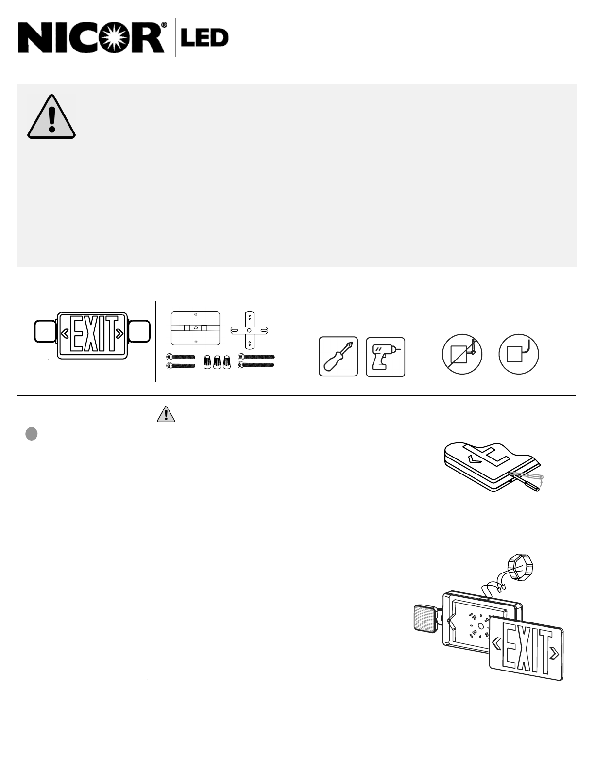
What’s In The Box
One (1) ECL3 One (1) Mounting Kit
Installing the ECL3
1
Preparation
• Carefully unpack the exit sign from its packaging.
• Inspect product for defects due to shipping.
•
Use screwdriver to carefully remove the front faceplate (See Figure 1)
Mounting and Wiring
Wall Mount (See Figure 2)
•
Use screwdriver to carefully remove the front faceplate.
•
Remove the knock out hole on the center of back plate. Then
remove the oblong knock outs on the back plate that correspond to
junction box holes to be used.
•
Remove the side hole plugs from the housing and snap the lamp
heads onto the unit.
•
Connect the lamp head wiring to the circuit board.
•
Route supply wiring through the center hole and into the housing.
•
Install the xture on the junction box using the (2) included screws
(#8-32)
•
Connect the wiring per the wiring diagram and push excess wire
into the junction box.
•
Attach the battery connector to the circuit board.
•
Snap out the desired chevron marking(s) from the front faceplate,
reinstall the faceplate and adjust the direction of the lamp heads as
needed.
Make sure all power is turn ed o before beginning installati on
Tools Needed
A Phillips screwdriver will be needed to install the ECL3.
A drill is needed to remove the knockouts if back
mounting.
Flexible Conduit Only
Figure 1 - Faceplate Removal
Figure 2 - Back Mount
NICOR, Inc. 2200 Midtown Place NE, Albuquerque, NM 87107 P: 800.821.6283 F: 800.892.8393 www.nicorlighting.com July 26, 2021 10:46 AM
Page 2
Installing the ECL3
2
Mounting and Wiring
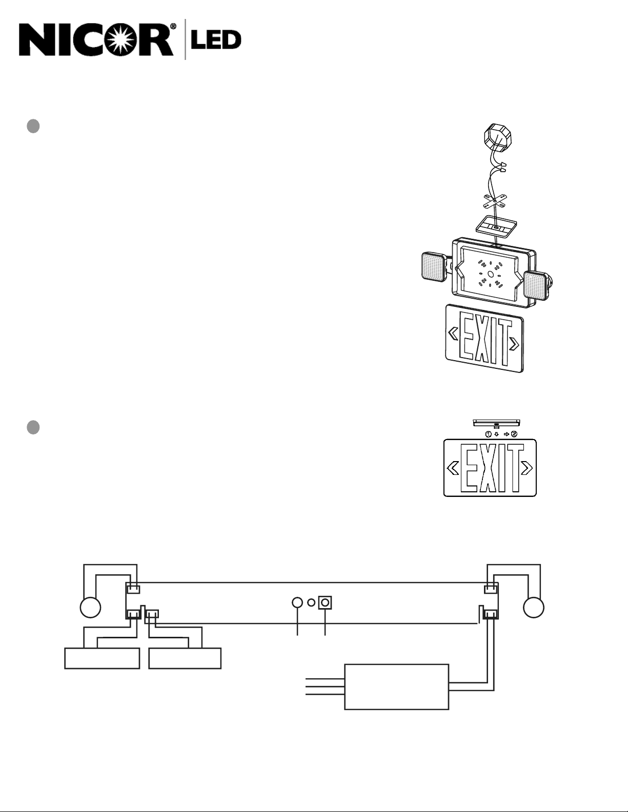
Ceiling Mount (See Figure 3)
•
Attach crossbar to junction box so that the short blade is touching
the box.
•
If double face is desired, replace back plate with additional faceplate
provided.
•
Remove the side hole plugs from the housing and snap the lamp
heads onto the unit.
•
Connect the lamp head wiring to the circuit board.
•
Remove the mounting hole cover on the top of the unit and
assemble the canopy to the unit (Figure 4)
•
Route xture wiring through the mounting hole and out of the
canopy.
•
Connect the wiring per the wiring diagram and push excess wire
into the junction box.
•
Install the xture on the junction box using the (2) included screws
(#8-32) and fasten the canopy to the crossbar.
•
Attach the battery connector to the circuit board.
•
Snap out the desired chevron marking(s) from the faceplate(s),
reinstall the front faceplate and adjust the direction of the lamp
heads as needed.
ECL3 Slim LED Combo Exit Sign & Emergency Light
INSTALLATION INSTRUCTIONS
Model: ECL310UNVWHG2SD, ECL310UNVWHG2RSD,
ECL310UNVWHR2SD, ECL310UNVWHR2RSD
Figure 3 - Top Mount
3
Connection of remote emergency lights (if applicable)
• Use Pink and Black wires for remote xture(s).
• Route wires outside of xture separately or with AC supply wires.
• Makes sure to keep all wires out of the way of the EXIT LEGEND so
there are no shadows.
Pink (+)
Black (-)
LED
Red(+) Black (-) Red(+ ) Black (-)
LED BOARD
Ready
Battery
2.4 VDC 1Ah
Battery
1.2 VDC 1Ah
Light
Black (120Vac)
Orange (277 Vac)
White (Comm)
Figure 4 - Canopy Attachment
Pink (+)
Black (-)
LED
Test
LED DRIVER
Figure 5 - Wiring Diagram
NICOR, Inc. 2200 Midtown Place NE, Albuquerque, NM 87107 P: 800.821.6283 F: 800.892.8393 www.nicorlighting.com July 26, 2021 10:46 AM
Page 3
ECL3 Slim LED Combo Exit Sign & Emergency Light
INSTALLATION INSTRUCTIONS
Model: ECL310UNVWHG2SD, ECL310UNVWHG2RSD,
4
Operating status:
When AC power is supplied to the xture, the unit will automatically initiate a self-test and self-diagnostic test as
follows:
1. Veries battery disconnection, charger board failure, lamp failure and transformer failure every 5 seconds.
2. One minute self test every month
3. 30 minute self test on the 6th month of the year after installation
4. 90 minutes self test on the 12th month of the year after installation
Note: All functions are pre-set at the factory and do not require eld adjustment.
5
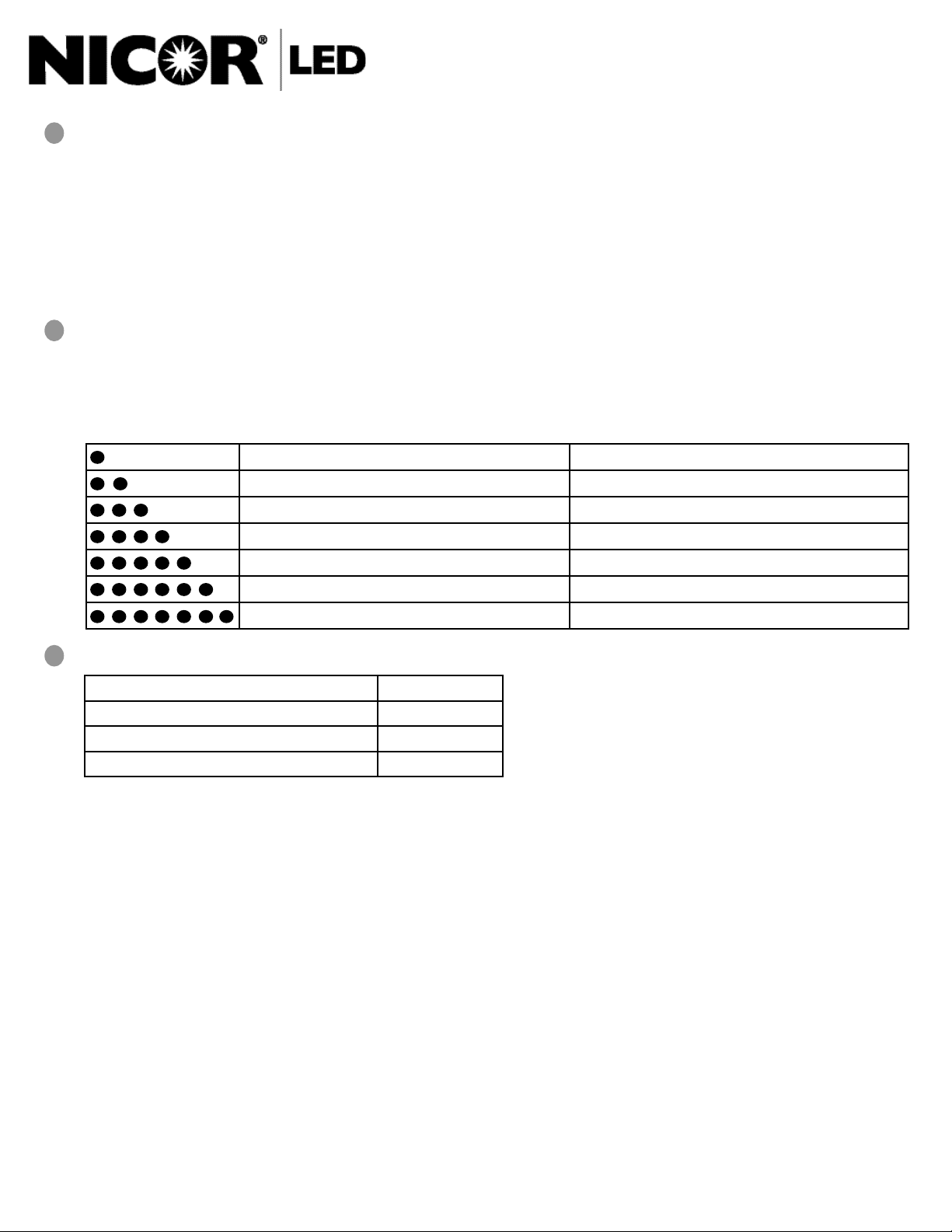
Indicator light status: Indicator is a dual color LED that shows the following status:
Green
1. Solid On : Ready
2. Blinking : Testing
Red - Service Alert
One blink ON/pause every 4 seconds Battery is not connected
Two blinks ON/pause every 4 seconds Battery voltage drops below acceptable value
Three blinks ON/pause every 4 seconds Charger board fault
Four blinks ON/pause every 4 seconds Transformer function failure
Five blinks ON/pause every 4 seconds Emergency lamp fault
Six blinks ON/pause every 4 seconds Remote head lamp fault
Seven blinks ON/pause every 4 seconds LED strip fault (Exit Sign)
ECL310UNVWHR2SD, ECL310UNVWHR2RSD
6
For manual test, press test button as follows:
Press test button once 1 minute test
Press test button 2x (within 2 seconds) 5 minute test
Press test button 3x (within 2 seconds) 30 minute test
Press test button 4x (within 2 seconds) 90 minute test
NOTE
Battery Testing: Allow 24 hours of charging before testing.
• Push In TEST Button - Fixture will switch to battery power and remain lit
• Release TEST Button - Fixture will switch back to AC power
GENERAL PRODUCT WARRANTY. Each NICOR product will be free from defect in materials and workmanship for a period of one (1) year from the date of delivery to the end-user. Powder Coat paint nish on products, other
than natural aluminum or brass, will not exhibit cracking, peeling, excessive fading, or corrosion during the warranty period. Exceptions apply as dened in each NICOR product’s specication sheets, which are incorporated
by reference herein. Warranty does not cover improper installation, operation, alterations, power surges, overheating due to external conditions, or acts of nature including but not limited to lightning strikes.
ALL NICOR WARRANTIES APPLY ONLY TO NICOR PRODUCTS THAT HAVE BEEN PURCHASED FROM AN AUTHORIZED NICOR DISTRIBUTOR; WHO PURCHASED THE PRODUCT DIREC TLY FROM NICOR; THE PRODUCT WAS NEW
AND IN AN UNOPENED NICOR PACKAGE AT THE TIME OF INSTALLATION; AND WAS INSTALLED BY A LICENSED ELECTRICIAN OR UNDER THE SUPERVISION OF A LICENSED ELECTRICIAN.
This device complies with part 15 of the FCC Rules. Operation is subject to the following two conditions: (1) This device may not cause harmful interference, and (2) this device must accept any interference received, including interference that may cause undesired operation.
NOTE: This equipment has been tested and found to comply with the limits for a Class B digital device, pursuant to part 15 of the FCC Rules. These limits are designed to provide reasonable protection against harmful
interference in a residential installation. This equipment generates, uses and can radiate radio frequency energy and, if not installed and used in accordance with the instructions, may cause harmful interference to radio
communications. However, there is no guarantee that interference will not occur in a particular installation. If this equipment does cause harmful interference to radio or television reception, which can be determined by
turning the equipment o and on, the user is encouraged to try to correct the interference by one or more of the following measures:
—Reorient or relocate the receiving antenna.
—Increase the separation between the equipment and receiver.
—Connect the equipment into an outlet on a circuit dierent from that to which the receiver is connected.
—Consult the dealer or an experienced radio/TV technician for help
NICOR, Inc. 2200 Midtown Place NE, Albuquerque, NM 87107 P: 800.821.6283 F: 800.892.8393 www.nicorlighting.com July 26, 2021 10:46 AM
 Loading...