

Page 1
CG
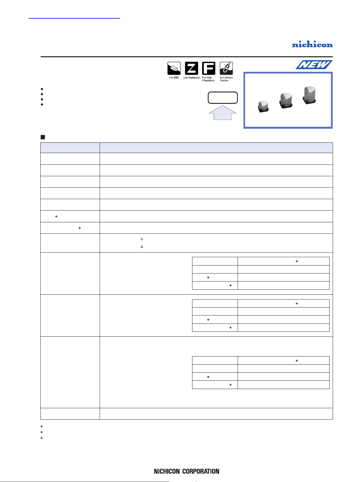
Higher Capacitance, Low ESR, High ripple current.
Load life of 2000 hours at 105
°C.
SMD type : Lead free reflow soldering condition at 260°C peak correspondence.
Adapted to the RoHS directive (2002/95/EC).
series
–55 to +105°C
2.5 to 16V
47 to 3300µF
± 20% at 120Hz, 20°C
Not more than value of Standard ratings at 120Hz, 20°C
Not more than value of Standard ratings at 100kHz, 20°C
Not more than value of Standard ratings. After 2 minute's application of rated voltage. 20°C
Z+105°C / Z+20°C 1.25 (100kHz
)
Z-55°C / Z+20°C 1.25
After 2000 hours' application of rated voltage
at 105°C, capacitors meet the specified value
for life characteristics listed at right.
After 1000 hours' application of rated voltage
at 60°C 90%RH, capacitors meet the specified
value for life characteristics listed at right.
To comply with recommended conditions for
reflow soldering. Pre-heating shall be done
at 150 to 200°C and for 60 to 180 sec.
In the case of peak temp, less than 250°C,
reflow soldering shall be within two times.
In the case of peak temp, less than 260°C,
reflow soldering shall be once.
Measurement for solder temperature profile
shall be made at the capacitor top and the
terminal.
Navy blue print on the case top.
CONDUCTIVE POLYMER
ALUMINUM SOLID ELECTROLYTIC CAPACITORS
1 ESR measurements should be made at a point on the terminal nearest where the ternimals protrude through the plastic platform.
2 Conditioning : If there is doubt about the measured result, measurement should be made again after the rated voltage is applied for 120 minutes at the temperature of 105°C.
3 Initial value : The value before test of examination of resistance to soldering.
Item Performance Characteristics
Category T emperature Range
Rated Voltage Range
Rated Capacitance Range
Capacitance T olerance
tan δ
ESR ( 1
)
Leakage Current ( 2
)
Characteristics of Temperature
Impedance Ratio
Endurance
Damp Heat
Resistance to
Soldering Heat
Marking
Capacitance change
tan δ
ESR ( 1
)
Leakage current ( 2
)
Within ± 20% of initial value ( 3
)
150% or less of the initial specified value
150% or less of the initial specified value
Initial specified value or less
Capacitance change
tan δ
ESR ( 1
)
Leakage current ( 2
)
Within ± 20% of initial value ( 3
)
150% or less of the initial specified value
150% or less of the initial specified value
Initial specified value or less
Capacitance change
tan δ
ESR ( 1
)
Leakage current ( 2
)
Within ± 10% of initial value ( 3
)
130% or less of the initial specified value
130% or less of the initial specified value
Initial specified value or less
Specifications
Chip Type, Higher Capacitance
CF
CG
Higher
Capacitance
查询PCG1A821MCL1GS供应商
Page 2
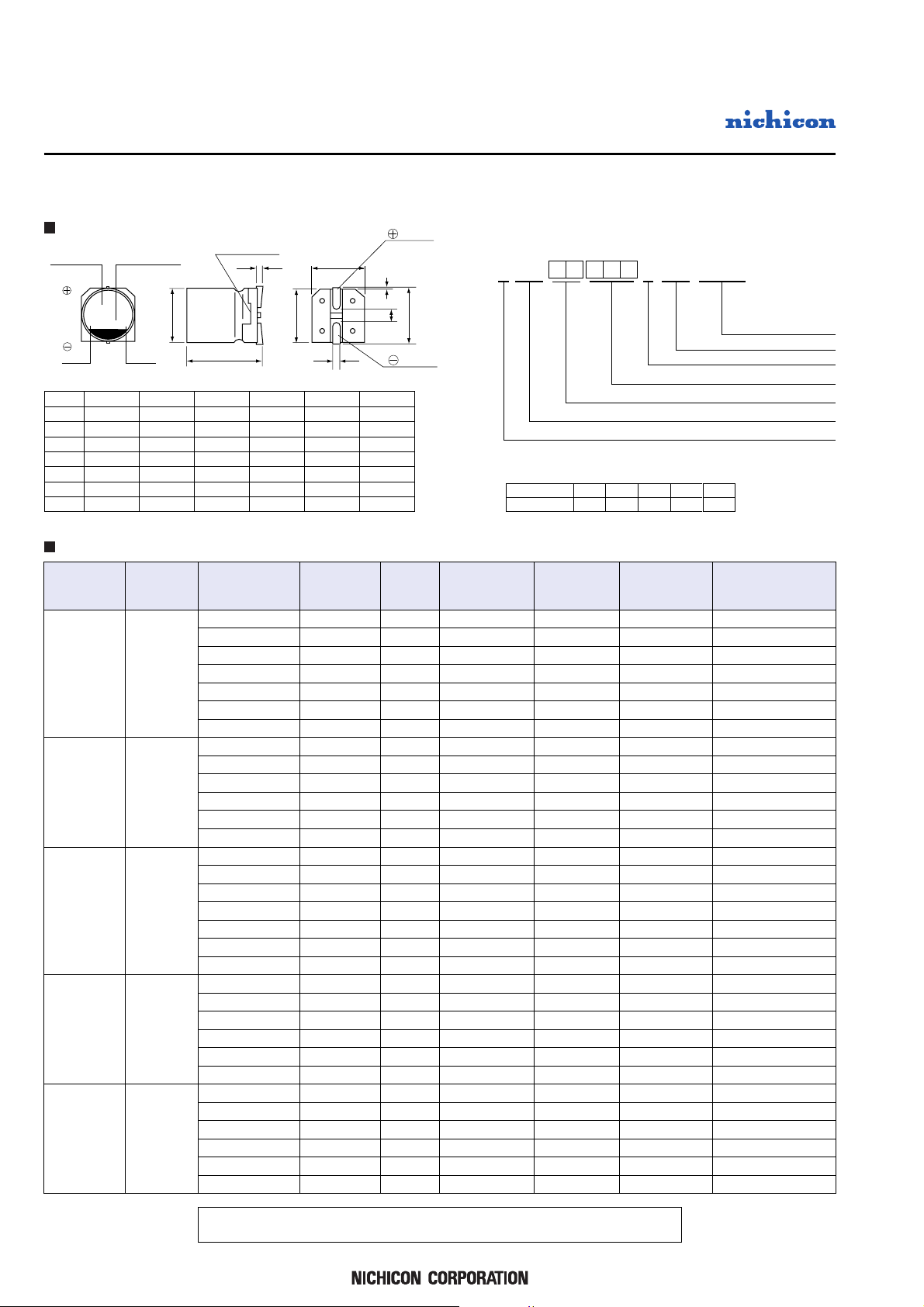
φ10 × 10Lφ10 × 8L
series
CG
CONDUCTIVE POLYMER
ALUMINUM SOLID ELECTROLYTIC CAPACITORS
Rated Voltage
(V)
Code
Rated Capacitance
(µF)
Surge Voltage
(V)
Leakage Current
(µA)
Case Size
φD × L
(mm)
2.5
(0E)
2.8
16
(1C)
10
(1A)
6.3
(0J)
4
(0G)
18.4
11.5
7.2
4.6
0.12
0.12
0.12
0.12
0.12
0.12
0.12
0.12
0.12
0.12
0.12
0.12
0.12
0.12
0.12
0.12
0.12
0.12
0.12
0.12
0.12
0.12
0.12
0.12
0.12
0.12
0.12
0.12
0.12
0.12
0.12
0.12
5 × 6
6.3 × 6
6.3 × 6
8 × 7
10 × 8
10 × 10
10 × 12.7
5 × 6
6.3 × 6
8 × 7
10 × 8
10 × 10
10 × 12.7
5 × 6
6.3 × 6
6.3 × 6
8 × 7
10 × 8
10 × 10
10 × 12.7
5 × 6
6.3 × 6
8 × 7
10 × 8
10 × 10
10 × 12.7
5 × 6
6.3 × 6
8 × 7
10 × 8
10 × 10
10 × 12.7
P1C2G304J5467718M9C10L11112G13S
14
Capacitance tolerance (±20%
)
Rated Capacitance (470µF
)
Rated voltage (6.3V
)
Series name
Configuration
Taping code
Type
Dimensions
Type numbering system (Example : 6.3V 470µF)
Standard ratings
ESR
(mΩ)
(
20˚C / 100kHz
)
Rated ripple
(mArms)
(
105˚C / 100kHz
)
φD
L
A
B
6.3
φ6.3 × 6L φ8 × 7L
5.9
7.3
6.6
8.0
6.9
9.0
8.3
Size
10.0
7.9
11.0
10.3
10.0
9.9
11.0
10.3
C
E
H
6.6
2.1
0.5 ~ 0.8
5.0
φ5 × 6L
5.9
6.0
5.3
5.3
1.2
0.5 ~ 0.8
8.3
3.2
0.8 ~ 1.1
10.3
4.6
0.8 ~ 1.1
10.3
4.6
0.8 ~ 1.1
φ10 × 12.7L
10.0
12.6
11.0
10.3
10.3
4.6
0.8 ~ 1.1
(mm)
tan δ Code
CG
470j741
H
0.3 MAX.
φD+0.5 MAX.
B±0.2
A±0.2
C±0.2
0.5 MAX.
E
L
Series
Voltage(j:6.3V
)
Plastic platform
Lot No.
Capacitance
Negative
Positive
+0.1
-0.4
Printed in Japan T.2007.B.3C
Design, Specifications are subject to change without notice.
V
Code
2.5e4
g
Voltage
6.3j10A16
C
PCG0E221MCL1GS
PCG0E471MCL1GS
PCG0E561MCL1GS
PCG0E821MCL1GS
PCG0E152MCL1GS
PCG0E272MCL1GS
PCG0E332MCL1GS
PCG0G181MCL1GS
PCG0G391MCL1GS
PCG0G681MCL1GS
PCG0G122MCL1GS
PCG0G222MCL1GS
PCG0G272MCL1GS
PCG0J151MCL1GS
PCG0J271MCL1GS
PCG0J331MCL1GS
PCG0J471MCL1GS
PCG0J102MCL1GS
PCG0J182MCL1GS
PCG0J222MCL1GS
PCG1A820MCL1GS
PCG1A151MCL1GS
PCG1A331MCL1GS
PCG1A561MCL1GS
PCG1A821MCL1GS
PCG1A102MCL1GS
PCG1C470MCL1GS
PCG1C820MCL1GS
PCG1C151MCL1GS
PCG1C271MCL1GS
PCG1C471MCL1GS
PCG1C681MCL1GS
220
470
560
820
1500
2700
3300
180
390
680
1200
2200
2700
150
270
330
470
1000
1800
2200
82
150
330
560
820
1000
47
82
150
270
470
680
110
235
280
410
750
1350
1650
144
312
544
960
1760
2160
189
340
416
592
1260
2268
2772
164
300
660
1120
1640
2000
150
262
480
864
1504
2176
30
20
20
20
17
12
10
32
22
21
17
13
11
33
23
23
22
18
14
12
35
25
23
20
15
13
40
30
28
25
20
18
2100
2900
3000
3300
4100
4700
5500
1900
2700
3200
4000
4600
5300
1800
2600
2700
3100
3800
4400
5000
1700
2500
3100
3600
4300
4800
1500
2300
2800
3300
3700
4100
 Loading...