

Page 1
NC-AD300E
PbX
User Manual
Page 2

NC-AD300E Manual
Foreword
The purpose of this manual is to supply operating, set up and configure with the
information needed to properly and quickly set up and configure the NiceUC's PBX
NC-AD300E .
We had made every effort to ensure that the information in this manual is accurate
and adequate.
If you use this manual when you encounter any problems and have any good
suggestions , please contact us:
ShenZhen NiceUC communication Tech Co., Ltd
Room 1401, YiZhe Building, YuQuan Rd, NanShan District,
ShenZhen City,GuangDong , China
Tel:86-755-26722761
Fax:86-755-26526970
Email: [email protected]
Website: http://www.nicecomm.com.cn
http://www.niceuc.com
- 2 -
Page 3

NC-AD300E Manual
Contents
Foreword........................................................................................................................... - 2 -
Contents.............................................................................................................................- 2 -
Chapter 1 Overview.......................................................................................................- 5 -
1.1 Brief introduction....................................................................................................... - 5 -
1.2 Main specialfication....................................................................................................- 5 -
Chapter 2 Hardware construction................................................................................- 5 -
2.1 Structure overview......................................................................................................- 5 -
2.2 Interface description...................................................................................................- 6 -
2.3 Hardware specification...............................................................................................- 8 -
Chapter 3 Installing Equipment...................................................................................- 9 -
3.1 Pre-installation preparation.......................................................................................- 9 -
3.1.1 Device Accessories..............................................................................................- 9 -
3.1.2 tools..................................................................................................................... - 9 -
3.1.3 Cable................................................................................................................... - 9 -
3.1.4 Enviroment.......................................................................................................- 11-
3.2 setup step................................................................................................................... - 13 -
3.3 Notes...........................................................................................................................- 13 -
Chapter 4 Basic configure...........................................................................................- 13 -
4.1 Terminalconnection................................................................................................. - 14 -
4.2 Command States.......................................................................................................- 15 -
4.2.1 Boot states.........................................................................................................- 15 -
4.2.2 Runing state......................................................................................................- 15 -
4.2.3 from the boot state to running state............................................................... - 15 -
4.3 Startup Parameters...................................................................................................- 15 -
4.3.1 Check boot parameters....................................................................................- 15 -
4.3.2 modify the boot parameters............................................................................- 16 -
4.4 Device IPAddress......................................................................................................- 17 -
4.4.1 View IP address................................................................................................- 17 -
4.4.2 modify the IP address...................................................................................... - 19 -
Chapter 5. Software configuration................................................................................- 20 -
5.1 tools............................................................................................................................ - 20 -
5.1.1 Connect device..................................................................................................- 21 -
5.1.2 Disconnect.........................................................................................................- 21 -
5.1.3 Read device parameters.................................................................................. - 21 -
5.1.4 Write device parameters................................................................................. - 22 -
5.1.5 Load Parameters..............................................................................................- 22 -
5.1.6 Export Parameters...........................................................................................- 22 -
5.1.7 Reset Device......................................................................................................- 22 -
5.2 Operation configuration...........................................................................................- 23 -
5.2.1 DSP function.....................................................................................................- 23 -
5.2.2 Telnet service....................................................................................................- 23 -
5.2.3 Login User........................................................................................................ - 23 -
- 3 -
Page 4

NC-AD300E Manual
5.2.4 E1 Configuration..............................................................................................- 24 -
5.2.4.1 Clock Source..........................................................................................- 24 -
5.2.4.2 PCM property....................................................................................... - 25 -
5.2.4.3 SS7 Signaling.........................................................................................- 28 -
5.2.4.4 V5.2 signaling........................................................................................ - 29 -
5.2.5Analog Line Configuration..............................................................................- 30 -
5.2.5.1 Line Type settings..................................................................................- 30 -
5.2.5.2Analog Signal Set.................................................................................. - 31 -
5.2.5.3 Call Detection Settings..........................................................................- 32 -
5.2.5.4 Line Volume Set.................................................................................... - 32 -
5.2.6666 Call control....................................................................................................- 33 -
5.2.6666.1 Length Rules........................................................................................- 33 -
5.2.6666.2 Routing Rule........................................................................................- 34 -
5.2.6666.3 Groups..................................................................................................- 42 -
5.3 Function Deployment............................................................................................... - 43 -
5.3.1 Ringback Tone settings....................................................................................- 43 -
5.3.2 Ring Duration time set.................................................................................... - 43 -
5.3.3Automatic recording settings.......................................................................... - 43 -
5.3.4 Subsriber line Number Configuration...........................................................- 44 -
5.3.5 User Password Configuration.........................................................................- 44 -
5.3.6 Call permissions...............................................................................................- 44 -
5.3.7 Hot number...................................................................................................... - 45 -
5.3.8 Call Forward Settings......................................................................................- 45 -
5.3.9 Do Not Disturb Setting.................................................................................... - 45 -
5.3.10 Number Convert............................................................................................ - 46 -
5.3.11login account setting.......................................................................................- 46 -
5.3.12 Multi-routing backup.................................................................................... - 46 -
Chapter 6 Calling detail records....................................................................................- 47 -
6.1 txt format...................................................................................................................- 49 -
6.2 Database format........................................................................................................- 49 -
Chapter 7. Debug monitor............................................................................................. - 50 -
7.1 Initialization Information.........................................................................................- 50 -
7.2 Equipment Command.............................................................................................. - 51 -
7.3 calling trace............................................................................................................... - 53 -
7.4 E1 monitor.................................................................................................................- 53 -
Appendix 1. The use of Hyper Terminal.......................................................................- 56 -
Appendix 2. Toestablish FTP services..........................................................................- 58 -
Appendix 3. Recording tone and load to PBX..............................................................- 59 -
Appendix 4. Equipment software upgrades................................................................. - 61 -
Appendix 5. Equipment software upgrades................................................................. - 62 -
Appendix6.SS7signaling messages introduction.......................................................... - 63 -
- 4 -
Page 5

NC-AD300E Manual
Chapter 1 Overview
1.1
Brief introduction
NC-AD300E , a small-capacity and multi-functional PBX, which is designed by Nice
communication company.it provide E1/T1,FXO,FXS interface,and can bring a new generation of
IP-based voice network to connect to the traditional trunk device, such as public switched
telephone network (PSTN) of the end office or tandem Bureau, or the enterprise's a small switch
(PBX). NC-AD300E PBX has its powerful signaling protocol handling and exchanging capability,
supporting most CTI functions like voice, meeting etc.
1.2 Main specialfication
* Media transfer between PSTN and IP network.
* Multi router、inter-office management, Intelligent router distribute and telephone traffic
sharing
* CDR output support TCP or UDP
* Grouping switching management, have PBX function like:
* Pre-recording voice attendance
* Busy call transfer
* Pre-set call transfer
* Do not disturb function
* Limit extension call out with account and password
* Caller ID display
* Add or cut prefix of dial number
* Voice recording (Optional)
* Meeting function (Optional)
* Provide CTILinkAPI interface for user program control
Chapter 2 Hardware construction
2.1 Structure overview
AD300E divided into three parts: Power,master control exchange,line module. The major
job for the Power is to complete AC Power Supply. Then master control change complete system
control and management,while line module provide all kinds of function interface.
- 5 -
Page 6
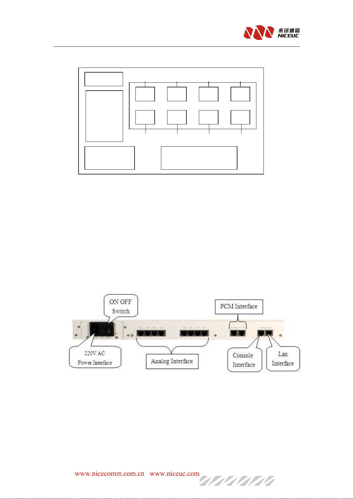
Internal structure of the diagram is as fllows:
Back interface
NC-AD300E Manual
module
0-3 8-11 16-19 24-27
(1)
((((3333))))
((((5))))
((((7))))
Main
Control
Board
(2)
4-7 12-15 20-23 28-31
((((4))))
((((6))))
((((8))))
Power moduleLink strem power
Front indicator parts
AD300E can set up two kinds of modules: FXO and FXS card, each card has four lines. The
maxium of a single device can be set up eghit cards, totally 32 lines.the sequence of FXS\FXO
cards are as shown from (1) to (8), and the number 0 to 31 is the sequence of analog lines.
.
2.2 Interface description
Interface to the back of the device:
The
The back
back of
of 300E
300E as
as shown
TheThe
backback
ofof
300E300E
asas
shown::::
shownshown
Power: 220VAC;
PCM interface:provide the corresponding number on-demond, and it can support
E1 and T1 currently.
E1 is the ITU-T developed by the European Association of Postal and
Telecommunications (CEPT) digital transmission system named after a group of (ie, PCM30)
standard, from 32 64kbps way through the words of the PCM time-multiplexed to form, its
transmission rate is 2.048Mbps . Usually 30, then road transport of voice and other user
information, the other two telephone channels as the system overhead, transmission
- 6 -
Page 7
NC-AD300E Manual
synchronization code, signaling yards and other ancillary signals. E1 interface of the
physical and electrical characteristics comply with the G.703 standard of CCITT.
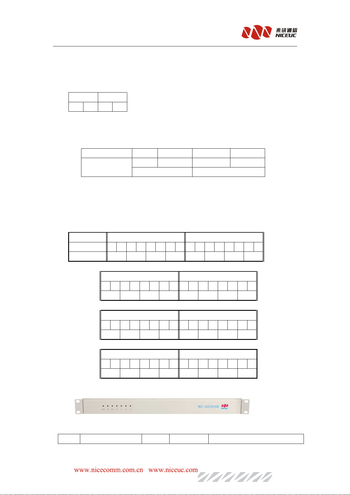
PCM sequence as shown:
PCM1 PCM0
TX2 RX2 TX1 RX1
Console and ethernet port :to be used as configure and debugging .with RJ45 connector.
And ethrnet port is a 10/100 Base-T Ethernet interface,support IEEE802.3
Reset button:can be used to reset device.
PCM RJ45 interface switch coax sequence:
RJ45 line sequence 1 2 4 5
BNC line sequence out(ring) inner (tip) out(ring) inner(tip)
RX TX
Analog interface:to connect telephone line,totally eight interfaces from UC1 to UC8.with
RJ45 connector. the sequence as shown:
表 2-2-2
interface UC8 UC7
Pin number 1 2 3 4 5 6 7 8 1 2 3 4 5 6 7 8
Line number 28 29 30 31 24 25 26 27
UC6 UC5
1 2 3 4 5 6 7 8 1 2 3 4 5 6 7 8
20 21 22 23 16 17 18 19
UC4 UC3
1 2 3 4 5 6 7 8 1 2 3 4 5 6 7 8
12 13 14 15 8 9 10 11
UC2 UC1
1 2 3 4 5 6 7 8 1 2 3 4 5 6 7 8
4 5 6 7 0 1 2 3
The front of the device as shown:
Light followed:
Power Eth Run S1 L1 S2 L2
Type
Type IIIIndicate
TypeType
ndicate NNNNormal
ndicatendicate
ormal AAAAbnormal
ormalormal
bnormal TTTThe
bnormalbnormal
he methods
hehe
methods of
methodsmethods
of solution
ofof
solution
solutionsolution
- 7 -
Page 8

NC-AD300E Manual
Power
Power Power status On Off Check the power
PowerPower
Eth
Eth Network status On Off Check the cable
EthEth
Run
Run Running status Flicks On/off Check device setup
RunRun
S1
S1 PCM0 sync indicate Off On/flicks Check E1 line connection
S1S1
L1
L1 PCM0 link indicate Off On Check signaling configuration
L1L1
S2
S2 PCM1 sync indicate Off On/flicks Check E1 line connection
S2S2
L2
L2 PCM1 link indicate Off On Check signaling configuration
L2L2
RRRR save
Note:The link indicator is relationship with configuration,it’s take effect when configuration to.
Tips:You
Tips:You can
Tips:YouTips:You
according
according to
accordingaccording
can dertimine
dertimine whether
cancan
dertiminedertimine
to sync
sync indicator.
syncsync
indicator.
indicator.indicator.
toto
whether the
whetherwhether
the E1
thethe
E1 connection
connection ,send
E1E1
connectionconnection
,send and
,send,send
and recive
andand
recive is
reciverecive
is correct
isis
correct
correctcorrect
2.3 Hardware specification
Nice AD-300E with 1U- high chassis, 19 inch width .dimension:480*365*40mm ,very easy to
install in 19-inch cabinet
Power
Power eqipment
PowerPower
E1(2M
E1(2M PCM)
E1(2ME1(2M
Analog
Analog module
AnalogAnalog
eqipment
eqipmenteqipment
Full
Full load
load power
FullFull
PCM)
PCM)PCM)
PPPPhysical
hysical interface
hysicalhysical
Framing
Framing structure
FramingFraming
G.796multi-frame structure
PCM
PCM base
Warning
III
base group
PCMPCM
basebase
Warning:compliance with the protocol G.775
WarningWarning
Jitter
Jitter and
JitterJitter
module technology
modulemodule
Interface
nterface type
nterfacenterface
power:60W
loadload
powerpower
interface:protocol G.703,unbalanced 75Ω.
interfaceinterface
structure : Compliance with the agreement G.732 frame and
structurestructure
group 2048KBps:Compliance with the protocol G.732&G.796
groupgroup
and drift
drift:Compliance with the protocol G.823
andand
driftdrift
technology indicator
technologytechnology
type:Analog trunk
typetype
indicator
indicatorindicator
Interface
Interface impendence
InterfaceInterface
Frency
Frency :300Hz~3400Hz
FrencyFrency
DDDDigital
igital voice
igitaligital
DTMF
DTMF code
DTMFDTMF
CCCCalling
alling monitor
allingalling
impendence:600 Ohm
impendenceimpendence
voice:A_Law PCM
voicevoice
code :0~9、*、#、A、B、C、D
codecode
monitor:signal ,voice,polarity reversal
monitormonitor
- 8 -
Page 9

CCCCaller
aller number
alleraller
FAX
FAX:FAX Group 3
FAXFAX
number:FSK、DTMF
numbernumber
Chapter 3 Installing Equipment
3.1 Pre-installation preparation
3.1.1 Device Accessories
Accessories list
accessories number unit note
Power line 1 article
console line 1 article
NC-AD300E Manual
ethernet line 1 article Crossover cable
E1 /T1 line 2 pair RJ45-2 BNC
data CD 1 piece
3.1.2 tools
Essential: Screwdriver, Crystal head pressure pliers,Wire cutter.
Optional:Multimeter,Electric iron,Solder wire,Knife,Needle nose plier,Etc.
3.1.3 Cable
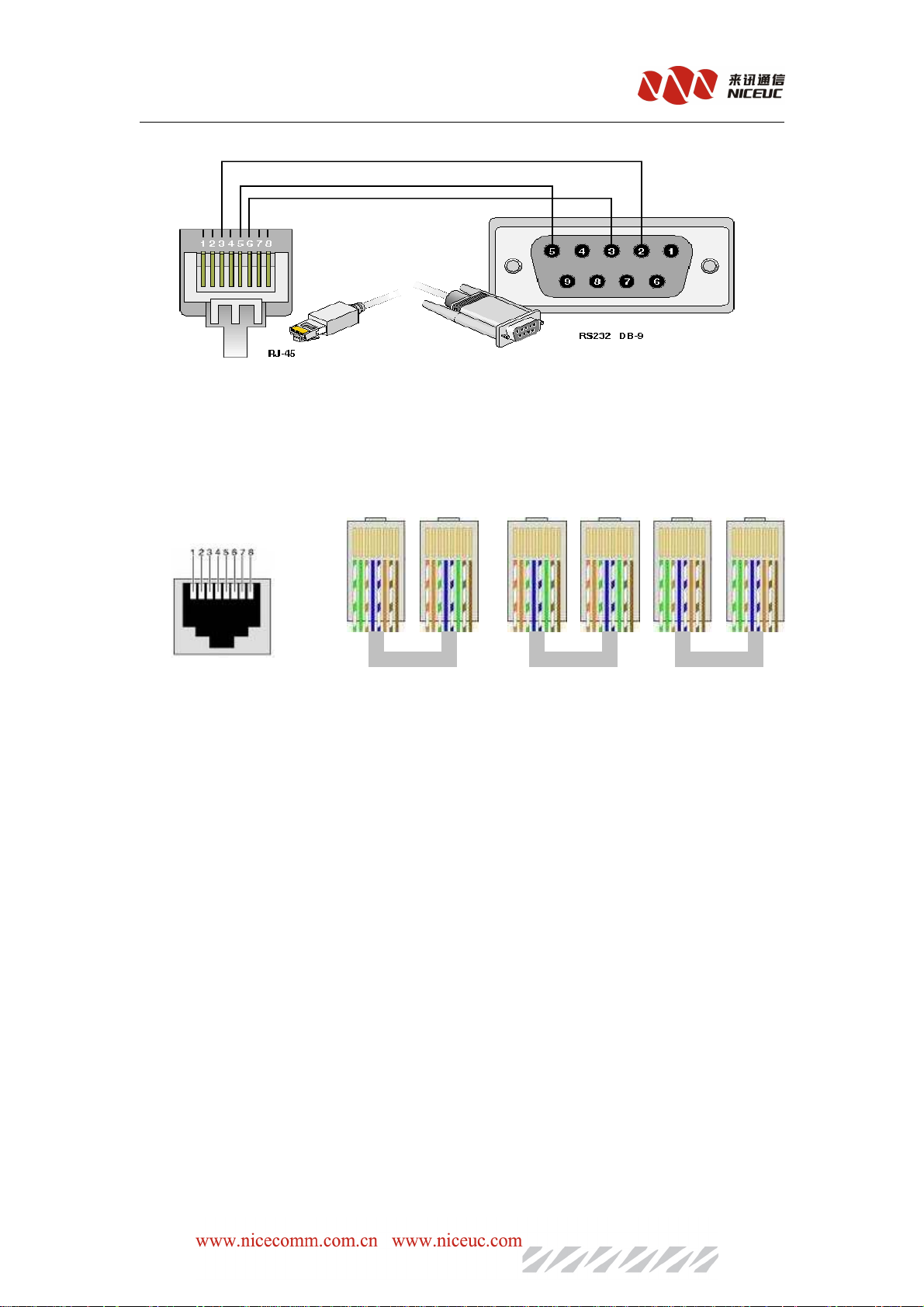
Console line: End of RJ45 crystal head,access device.and the other side of RS232 DB
Female head,then link to computer.
The realationship from console RJ45 to RS232.
- 9 -
Page 10
NC-AD300E Manual
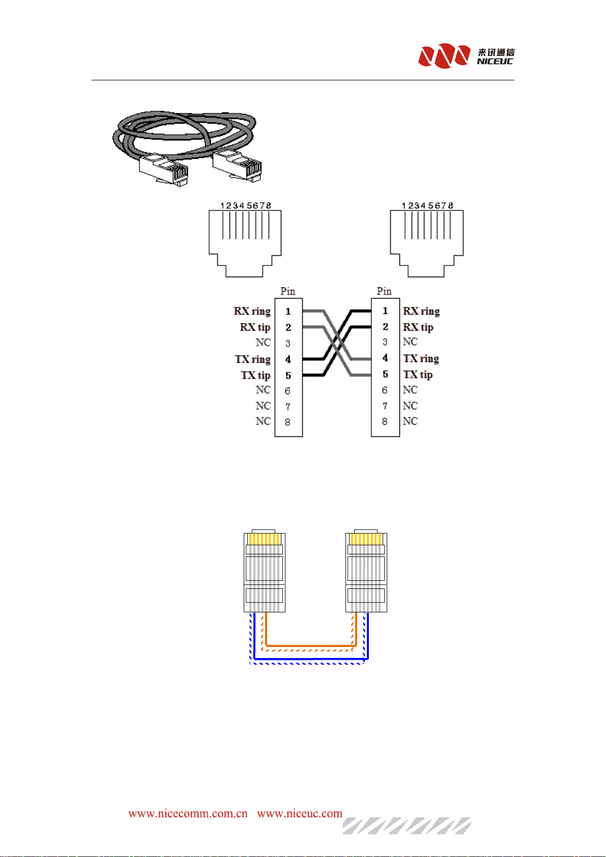
There are two kinds of network cable ,one is Crossover cable the other is straight-through.
If device connect to computer ,please use Crossover cable.If connect to HUB,use StraightThrough cable.
Network cable at both end of RJ45 line sequence as shown:
cross
cable
straight straight
- 10 -
Page 11
E1 line interface of RJ45 as shown:
NC-AD300E Manual
E1 line ,usually config RJ45 transfer line BNC,if the opposite end of the side is RJ45.You
can DIY it according the fllowing diagram:
3.1.4 Enviroment
a) Power Requirements:
Voltage should be constant, the electric current should be sufficient (to meet the nees OK),
Power can’t have too much clutter and interference.
- 11 -
Page 12

NC-AD300E Manual
Power type UPS or Secondary power supply
Nominal voltage 220VAC -48V DC
Voltage input range
130v~250v normal -48V±15% ensure indicators,
-57V~-40V normal work
b) Grounding Requirements
The engine room must have good grounding,and have separate protected. room of the
lighting protection system should be a separate system. its grounding system and used as a
reference to the power system and protected room is not shared.
c) Temperature and Humidity
Toensure the device work normally and to extend the service life ,engine room needs to
maintain a certain temperature and humidity, If the room humidity is too high for a long period, it
could easily lead to bad insulation or insulation leakage, and also occurs materials, mechanical
properties change in such phenomena as corrosion of metal parts; if the relative humidity is too
low, causing shrinkage of insulating gasket will screw loose, in the dry weather conditions, but
also prone to static electricity, against device electronics; if the temperature is too high will
accelerate the aging process of insulating materials, so that the reliability of the device greatly
reduced, seriously affecting their life.
Temperature Humidity
Transport and
storage
-20℃~60℃ 0℃~40℃ -5℃~45℃ 5%~85% 5%~90%
Description
Long-term work
conditions
The engine room temperature and humidity measurement refers to the equipment
rack before and after the failed to protect boards from the floors above 1.5m and 0.4m
from the equipment rack at the front of the measured values.
Short-term work refers to device work conditions, working continuously for less than
24 hours and an annual aggregate of not more than 15 days
Short-term work
conditions
Long-term work
conditions
Short-term work
conditions
d) Others
The major harzard of device running safty is dust, that indoor dust attched to the
body ,leads to electrostatic adsorption, the metal connectors or metal contacts being exposed,
not only will affect the service life, but also easily lead to communication failures. When the
indoor relative humidity low, the easier to produce this electrostatic adsorption. Therefore,
dust needs to be done.
Despite the anti-lightning equipment has done a lot of considerations, but also taken the
necessary design and measures, but the lightning intensity over a certain area, it is still possible to
cause damage to equipment. In order to achieve a better lightning effectsit is recommended users:
Ensure the equipment chassis of protected areas with the protection of ground to maintain
- 12 -
Page 13

NC-AD300E Manual
good contact with the earth
.
To enhance the power of the anti-lighting effect,we can consider the input front-end to join
in the power supply arrester, so that power can be greatly enhanced the ability of
anti-lightning strike. To enhance the power of the anti-lightning effect
For the device itself by the user interface to connect to the outdoor outlet signals, such as
telephone lines, E1/T1 lines, in order to achieve better anti-lightning effect, users may wish to
consider the input of additional signal lines dedicated lightning devices
And need to note that electromagnetic interference, with particular attention to
anti-static. when the observation or the transfer of the demolition of the circuit board, please
contact the circuit board by hand the outer edges to avoid touching the circuit board by hand
directly to components.
3.2 setup step
At frist please install device and fixed , and then connect the power cord, turn the power
switch, observation equipment, lights are normal. To normal, to connect serial cable, network
cable, and configure the operating parameters. Configuration is completed, connecting E1 lines.
E1 line to connect when you should pay attention to the corresponding synchronous receive light,
if the red light, try to connect the TX and RX pairs of words, the red light does not shine can be.
3.3 Notes
A. Ground must have good grounding resistance should be less than 5 ohms, preferably less
than 0.5 ohms.
B. Docking cable, the interface card bits to be solid, appropriate driving force can not fall.
C.Pull line, pay attention to circlip, must not use brute force, may cause damage to cable
connectors.
D. Don’t connect PSTN line to FXS port, otherwise will cause the FXS module damage
Chapter 4 Basic configure
NC-AD300E can be configured by two means.
1.Through the console port to connect terminal or PC running terminal emulation software.
- 13 -
Page 14
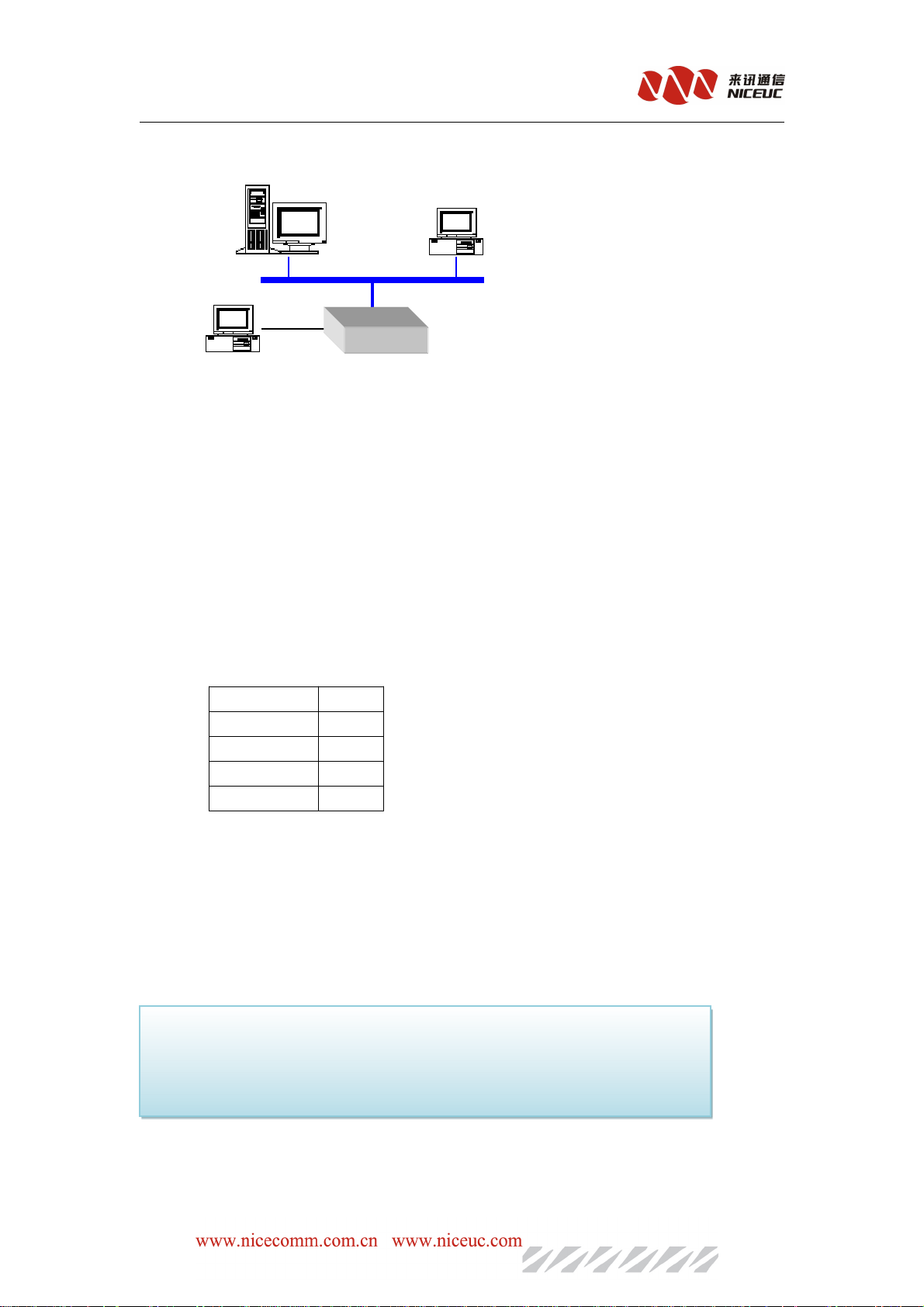
2.Through Telnet program on the Ethernet.
FTP Server
NC-AD300E Manual
Telnet
Ehternet
Console
Console
terminal
AD300E
But before use the Telnet,we need to know IP address of the device, and ensure the internet
smoothly.
4.1 Terminal connection
Weusually use PC to debugging device,when connecting to device console port,it needs to
running a simulation software on PC, In Windows system, the commonly used "Super Terminal."
you can also use any other terminal software, recommended the use of SecureCRT.
Use of methods about “Super Terminal” can be found in Appendix II or other materials
When use console port,terminal parameter configuration as shown:
Baud rate 115200
Data bits 8
Parity None
Stop bits 1
Flow Control None
Notes: Computer usually have two serial ports,COM1 and COM2,if it’s out withUSB-Serial
port, then may be COM3,COM4,COM5 etc.please confirm the choice of the port is correct
。。。。
It can be use Telnet service through Ethernet connection,in Windows system, point “Start” menu
Then choose “Run”,and enter “address of IP” .you can also use other third-party software.such as
Secure CRT. Default of the telnet login name is admin ,password is nice.
Notes:at the same time ,console port and telnet connection only one,when the telnet
Connect ,the Console port will be limited .only when the telnet exit, console port
session can be restored . and through the Ethernet you may connect telnet only
one,if you have connected a telnet. Re-connect will be limited.
- 14 -
Page 15

NC-AD300E Manual
4.2 Command States
There are two status for device, after a normal boot into the running.if the startup was
interrupted, it will enter the Boot Status.
4.2.1 Boot states
When the device starts, if it has been connected to the terminal, you can see the start of the
initialization information.
When the Press any key to stop auto-boot ... are prompted to wait for a few seconds delay,
then press any key can stop the system start up and goes to boot state, and "[Boot]:" prompt will
be shown.
In boot state, the equipment is waiting for the basic parameter change such as network
parameters, boot methods.
4.2.2 Runing state
After start up finished the Equipment will go to running state, the prompt is "->" "In PC
terminal,you can view and modify the equipment operating parameters. Running a large number
of functions under the command will be described later.
Note that all commands are case-sensitive.
4.2.3 from the boot state to running state
In boot state, after the prompt of "[Boot]:" enter "x", the equipment will be loaded from the
Flash started into running state. If the FTP server has been configured, you can also type "@", the
equipment will be start to load the file from FTP server.
4.3 Startup Parameters
4.3.1 Check boot parameters
If in the boot state, "[Boot]:" enter "p"
If in running state, "->" , enter" pboot "
boot parameter as follows:
boot device :at the system boot device name
unit number :0 Number of startup equipment unit
- 15 -
Page 16

NC-AD300E Manual
processor number:0 number of processors
host name:server host name
file name:pbxe.st netloaded at startup from the network file names
inet on ethernet(e):192.168.16.254:FFFFFF00 device itself ipaddress:Subnet Mask
host inet (h):192.168.16.85 FTP host IP address of service
gateway inet (g):192.168.16.1 Ethernet Gateway IP adress
user (u) :ad300e connect FTP service user name
ftp password (pw):nice connect FTP service password
flags (f):0x0 boot parameters
DeviceID :0x0 device ID
4.3.2 modify the boot parameters
If in boot state, "[Boot]:" type "c"
If in running state, "->" type “cboot”
Instructions:
Type the new value directly behind the old value, enter the changes, and then move to the
next one.
Enter ".", Then delete the current content.
Enter "-" then return to the previous row to make changes.
Enter "Ctrl + D", exit change.
Directly press enter, will move to the next one.
boot device: at0 can not be changed
processor number: 0 can not be modified
host name: server can be freely modified
file name: pbxe.st according to the actual file name changes
inet on ethernet (e): 192.168.16.254: FFFFFF00
Modification form must be filled, if not the subnet mask, default taken 255.255.255.0
host inet (h): 192.168.16.85
Upgrade by FTP software to use, usually do not need to modify
gateway inet (g): 192.168.16.1
Intenet using to access the gateway address, depending on the network situation.
user (u): ad300e according to practical situation
ftp password (pw): nice according to practical situation
flags (f): 0x0
Parameter values can be bitwise combination.
0x04 – go to the boot startup state, rather than running state.
0x08 - Quick Start to run state can not enter to boot state.
0x20 - Disable Telnet login account authentication.
0x40 - use DHCP to automatically obtain parameters.
- 16 -
Page 17

0x80 - load the boot image from tftp.
0x100 - use proxy arp service.
0x200 --
0x400 – load from ftp to boot
0x800 - manually set the MAC address.
0x1000 - start the DHCP service.
0x2000 - use watchdog.
target name (tn): e3 can be freely modified
startup script (s): must be empty
other (o): must be empty
DeviceID: 0x0 can be freely modified
Note that the modification will be effect after re-start up.
4.4 Device IP Address
4.4.1 View IP address
NC-AD300E Manual
A) ipconfig
Use the ipconfig command to query the device IP address for the primary user. Examples are
as follows
-> Ipconfig
ip = 192.168.16.100: ffff0000
the device IP address "192.168.16.100", the subnet mask for the hexadecimal form converted to
decimal as "255.255.0.0".
B) ifconfig
Use ifconfig command to query the device IP address for the primary user. Examples are as
follows
-> Ifconfig
ip = 192.168.16.100: ffff0000
the device IP address "192.168.16.100", the subnet mask for the hexadecimal form converted to
decimal as "255.255.0.0".
C) ifShow
Use ifShow command to view the device details of network parameters for advanced users.
Examples are as follows
-> IfShow
at (unit number 0):
Flags: (0x8063) UP BROADCAST MULTICAST ARP RUNNING
Type: ETHERNET_CSMACD
Internet address: 192.168.6.100
Broadcast address: 192.168.255.255
Netmask 0xffff0000 Subnetmask 0xffff0000
Internet address: 200.0.6.99
- 17 -
Page 18

Broadcast address: 200.0.6.255
Netmask 0xffffff00 Subnetmask 0xffffff00
Ethernet address is 08:00:3 e: a8: 06:64
Metric is 0
Maximum Transfer Unit size is 1500
323677 octets received
213766 octets sent
4596 packets received
4066 packets sent
2387 non-unicast packets received
7 non-unicast packets sent
2209 unicast packets received
4059 unicast packets sent
0 input discards
0 input unknown protocols
0 input errors
0 output errors
0 collisions; 0 dropped
lo (unit number 0):
Flags: (0x8069) UP LOOPBACK MULTICAST ARP RUNNING
Type: SOFTWARE_LOOPBACK
Internet address: 127.0.0.1
Netmask 0xff000000 Subnetmask0xff000000
Metric is 0
Maximum Transfer Unit size is 32768
0 packets received; 0 packets sent
0 multicast packets received
0 multicast packets sent
0 input errors; 0 output errors
0 collisions; 0 dropped
NC-AD300E Manual
D) pboot
Use pboot command to view the basic parameters of the device. Examples are as follows
-> Pboot
boot device: at
unit number: 0
processor number: 0
host name: server
file name: pbxe.st
inet on ethernet (e): 192.168.16.254:FFFF0000
host inet (h): 192.168.16.5
user (u):ad300e
ftp password (pw): nice
flags (f): 0x0
- 18 -
Page 19

NC-AD300E Manual
target name (tn): d
DeviceID: 0x0
The above example, "inet on ethernet (e):" is the device behind the IP address, and the
ifconfig command to see to the format, the device IP address "192.168.16.254the subnet mask for
the hexadecimal form of conversion into a decimal to "255.255.0.0".
4.4.2 modify the IP address
A) cboot
Use cboot command to modify the device's IP address, operating process is as follows:
-> Cboot
'.' = Clear field; '-' = go to previous field; ^ D = quit
boot device: at0 Enter
processor number: 0 Enter
host name: server enter
file name: pbxe.st Enter
inet on ethernet (e): 192.168.16.254: FFFF0000 Enter the new IP address + Enter
inet on backplane (b): Enter
host inet (h): 192.168.16.50 Enter
gateway inet (g): 192.168.16.1 Enter
user (u): pbxe Enter
ftp password (pw) (blank = use rsh): nice Enter
flags (f): 0x20 Enter
target name (tn): d Enter
startup script (s): Enter
other (o): Enter
DeviceID: 0x0 Enter
Instructions:
In the current row directly type the new value, press enter to change, and then move to
the next parameter.
Enter ".", Then delete the current content.
Enter "-" and return to the previous row to make changes.
Enter "Ctrl + D", exit changes.
directly press enter, then move to the next one.
IP address format is still IP: subnet mask, for example the IP address need to be changed to
10.1.123.145, subnet mask as 255.255.254.0, then need to type the value as: 10.1.123.145:
FFFFFE00
Note that the modification will be effect after re-start up.
B) ifconfig
Use ifconfig to set IP address can be effective immidiately. Examples are as follows
-> Ifconfig "192.168.16.105: FFFF0000"
- 19 -
Page 20
NC-AD300E Manual
ip set 192.168.16.105: ffff0000 ok
The example set IP address "192.168.16.105", the subnet mask for the hexadecimal form
converted to decimal as "255.255.0.0". ok means modification has been finished
Note: This method modify the IP to take effect immediately, but don’t save, even after reboot
take boot parameter.
Chapter 5. Software configuration
5.1 tools
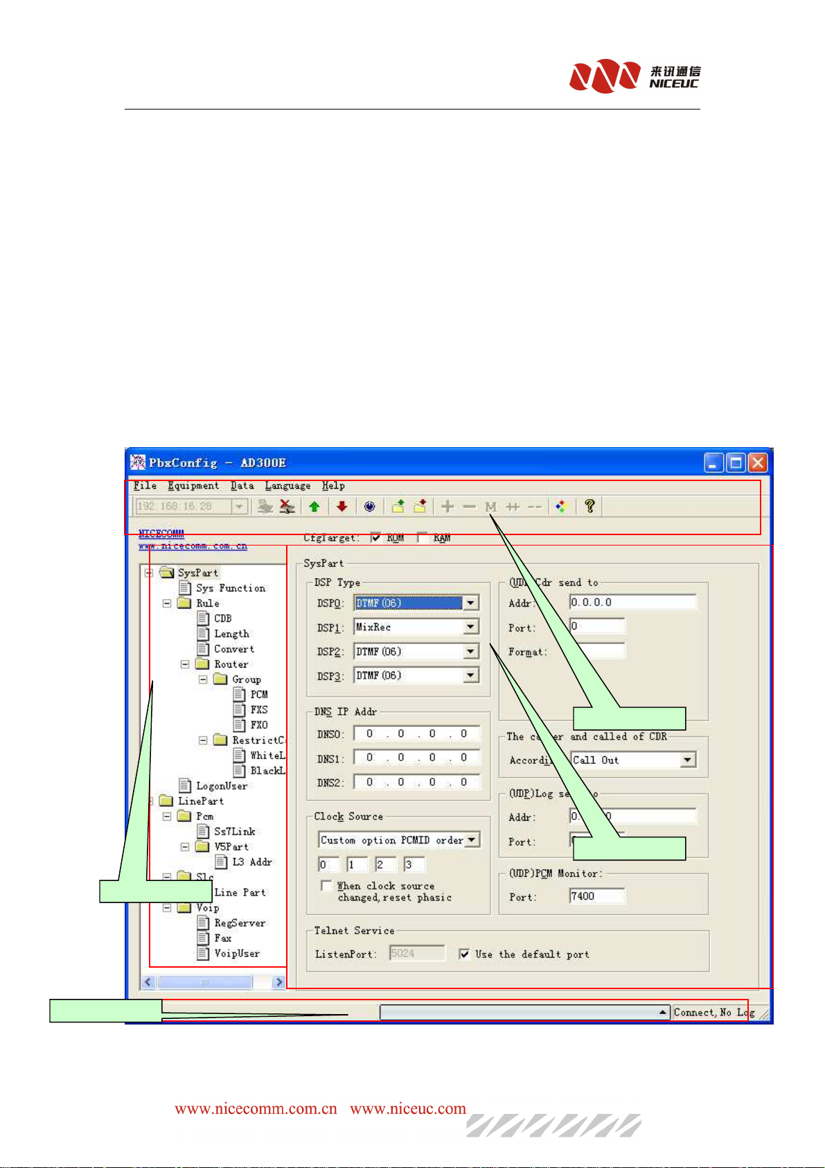
Run the tools of PbxConfig.exe,the tools looked as below:
2.Index
4.result message
Interface divided into four areas,
1.Operation
3.Parameter
- 20 -
Page 21
NC-AD300E Manual
1. Equipment operation, including menus and toolbars.
2. Parameter index is the device operating parameters of a classified index.
3. Parameters value displays the current parameters of the index of specific parameters.
4. Message showing relevant operational status and results
5.1.1 Connect device
First, fill in the correct device IP address, and then click Button or in the "Device" menu,
select "Connect." If the connection is successful, IP address bar will turn into gray, such as
, At the same time, the status bar will show "Connect".
5.1.2 Disconnect
Click Button or in the "Device" menu, select "Disconnect." If successful disconnect, IP
address bar will restore inputable, such as , At the same time, the status
displays "Not Connected."
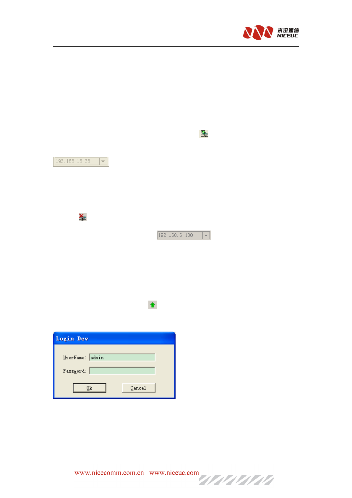
5.1.3 Read device parameters
After a successful connection, point Button or in the "Device" menu, select "read." Will
be prompted to enter a user name and password
The default user name admin, password is nice
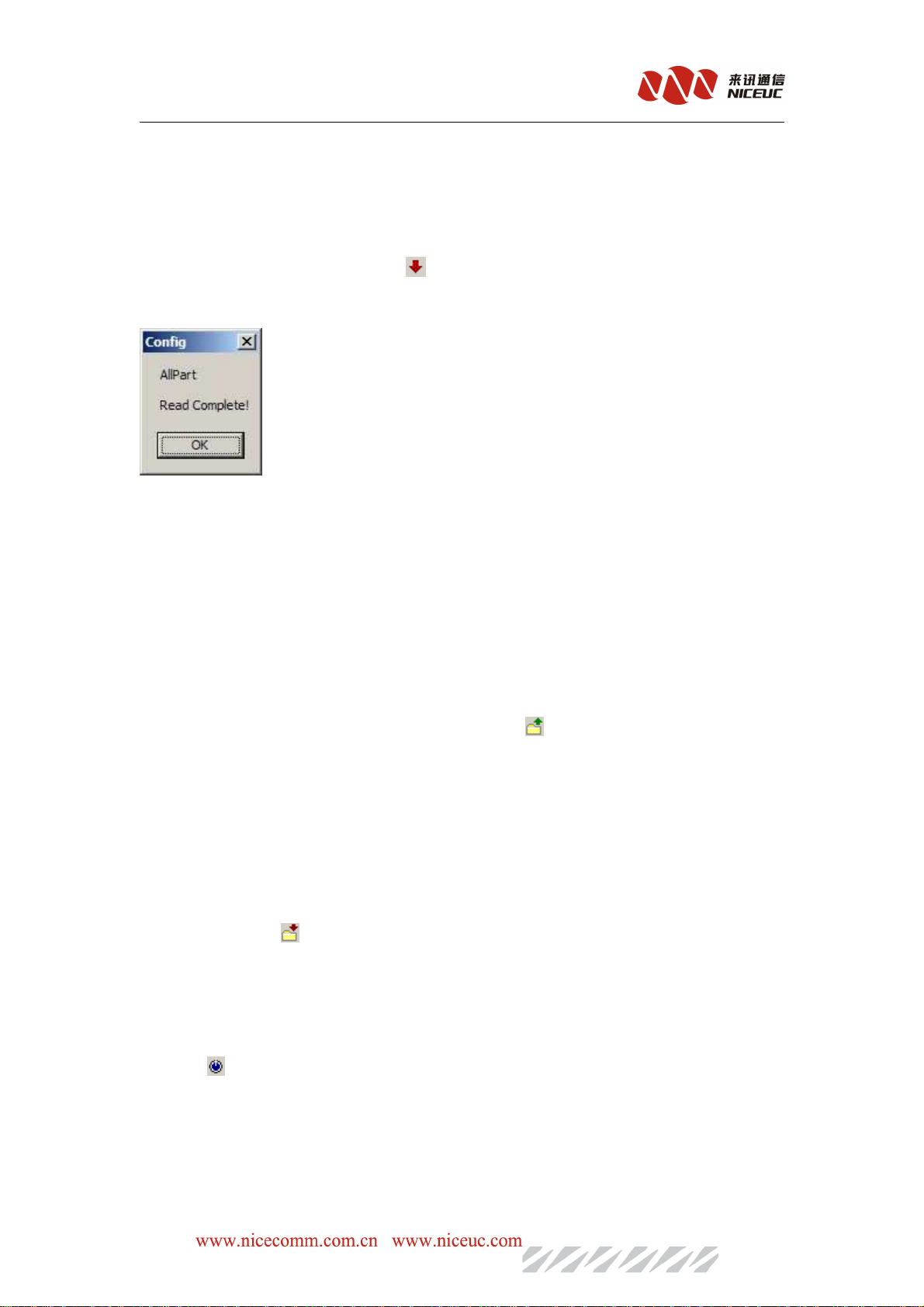
If the parameter was successfully read, read out all parameters will be prompted to complete.
For this operation, you need to pay attention "to read and write target" option. ROM is like
- 21 -
Page 22
NC-AD300E Manual
a computer's hard drive, RAM is the computer flash memory, can only choose one of them.
5.1.4 Write device parameters
After a successful connection, point Button or in the "Device" menu, select "Write."
If you write to the success of all the parameters will be prompted to write to finish.
Write operations, you need to pay attention "to read and write target" option. Write ROM
data is not lost after power-down, write RAM data will be lost after power-down, but some
parameters can take effect immediately (without restarting equipment with immediate effect). also
proposes to select the ROM and RAM in the same time for write operation.。
5.1.5 Load Parameters
Device parameters can be saved as a text file form. The text file can be loaded into the device,
commonly used to restore the backup configuration. Point Button or in the "File" menu,
select "Import."
Note that the import operation is just the parameters loaded into the buffer configuration
tool,and not written to the device.
5.1.6 Export Parameters
Device parameters can be saved as a text file. This is mainly for the back up the configuration
of the devices. Click Button or in the "File" menu, select "Export."
Note, remember to read the the device configuration before do the export action.
5.1.7 Reset Device
Click Button or in the "Device" menu, select "Reset", the equipment can be reset.
When modify parameters, it is recommended to read out the parameters of the device and import
to back up first, and try to back up for each modification to avoid mistake and can not be
recovered.
- 22 -
Page 23
NC-AD300E Manual
5.2 Operation configuration
5.2.1 DSP function
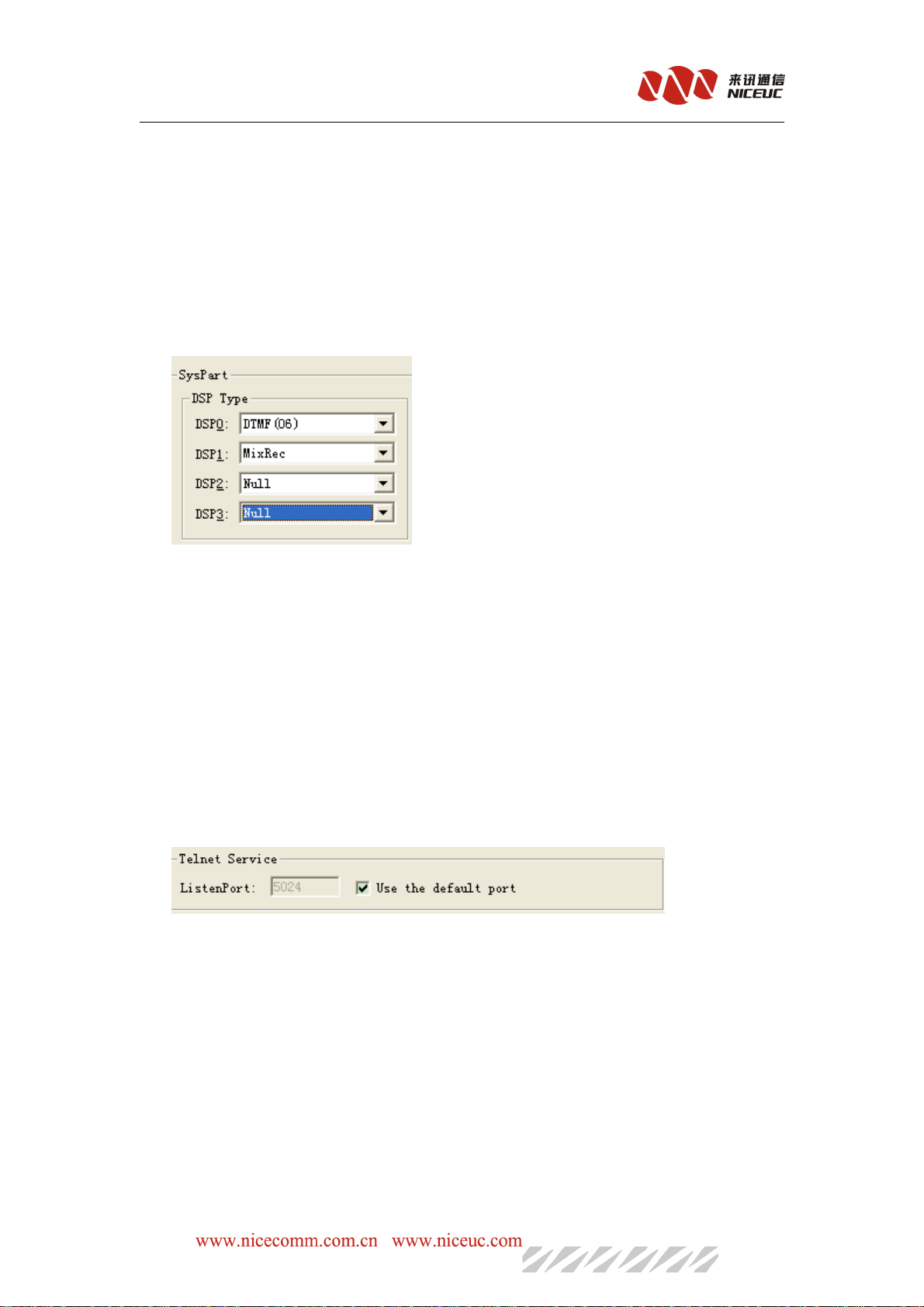
DSP function is the essential function of the device must be properly set up, In the left side of
configuration tool click"system parameters" index, and modify the parameters in the right side.
AD300E have two DSP,usually according above of the configuration
Note: you need to config “MFC/DTMF” or “DTMF(06)”to detail user button
After completion of editing, write to ROM and restart the device to take effect.
5.2.2 Telnet service
In the left side of configuration tool, pleas click"system parameters" index, and modify the
parameters in the right side
Here can modify telnet listenport
After completion of editing, write to ROM and restart the device to take effect.
5.2.3 Login User
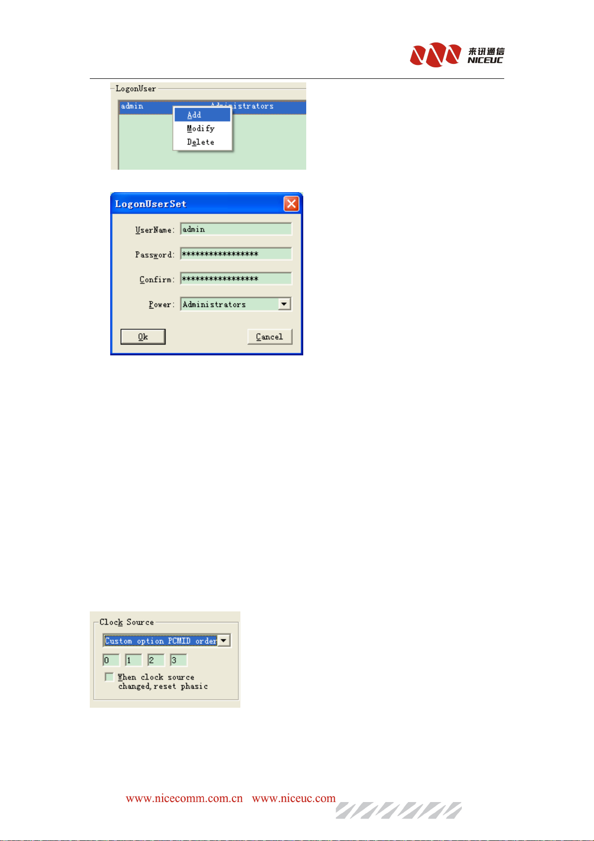
Specify the telnet connection and configuration tool for certified users, up to 10 users set up.
Choose “Loginuser” in parameter index area,and you can find there is loginuser list in the right
side. Using “data” menu,toolbar or right menu to do add and delete operation.
- 23 -
Page 24
NC-AD300E Manual
After completion of editing, write to ROM and RAM . restart the device to take effect.
5.2.4 E1 Configuration
If you need to use E1 lines, then the configuration of E1 is necessary. E1 transmission is
synchronized signals, using the call signaling control.
5.2.4.1 Clock Source
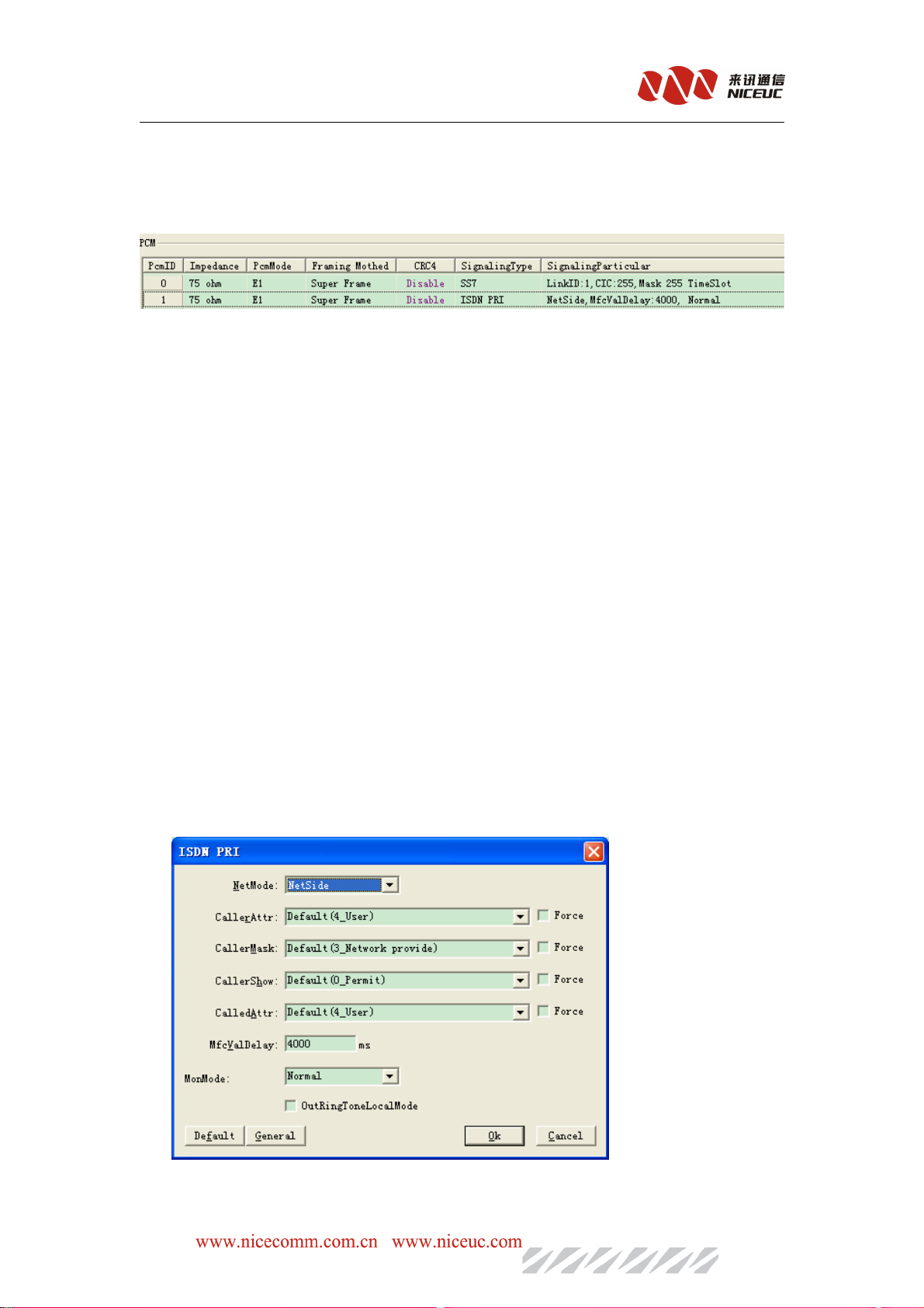
E1 clock synchronization signal needs to be unity for working properly. AD300E itself does
not provide the clock source, but it can get the clock from other side through E1.you can click
“system parameters ” index ,and modify E1 clock source on the right parameter area.
Tips: Usually get the clock source through PCM0
After completion of editing, write to ROM and restart the device to take effect.
- 24 -
Page 25
NC-AD300E Manual
5.2.4.2 PCM property
Set the relevant properties of PCM. In the INDEX area select the "PCM", Pamameter area
shows as below:
PcmID, PCM's number, see the hardware description.
Line impedance, E1 lines using coaxial cable connection typically use two kinds of 120-ohm or 75
ohm impedance.(if device interface is CC4 small head ,you can only us 75 ohm )
CRC4 check, physical frame of the 4-byte cyclic redundancy check. Normally enable.
Signaling type, set the signaling type of PCM.AD300E supports the following signaling.
A) ISDN PRI, or Primary Rate ISDN (Primary Rate Access), also known as Digital One
(DSS1) signaling, the domestic usually 30 B channels plus one D channel (30B + D)
approach.
B) SS7 signaling, SS7 signaling is a common international standard for common channel
(Common Channel) signaling system, which uses a layered functional structure and message
communication mechanism, the most suited for the use of modern digital communication
network. Currently AD300E support TUP (Telephone User Part) and ISUP (ISDN User
Part).
C) V5.2, to connect AN (Access Network) access network and the LE (Local Exchange) the
local exchange network V-interface.
Signaling parameters:signaling related to the detailed parameters.
ISDN PRI signaling has the following parameters:
Network mode: two options, the network side or user side. can not be the same at both ends.
- 25 -
Page 26
NC-AD300E Manual
Calling attributes, caller screening, caller display, called attributes, set the number of
properties, usually select the default value.
MfcVallDelay: When receiver number, if the number is passed by bit, will wait this value of
ms(second) for next bit. If longer than this time but did not receive next bit, then the number
receiving has been completed.
Usage pattern: usually choose "normal mode." "Signaling Collection" and "high-impedance
recording" in and line monitoring of the use of high barrier from the need for external devices can
be collected signaling, monitoring recording.
When the check the "ring-back does not pass through", the device will provide their own ring
back tone, rather than pass through the next level.
On the SS7 signaling parameters are as follows:
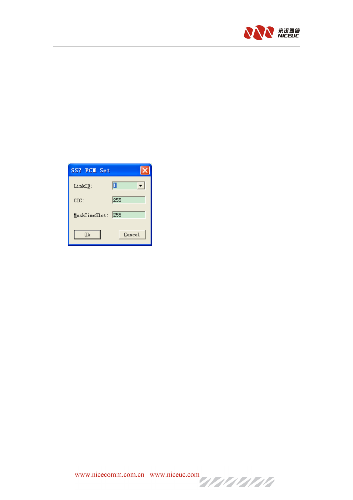
Link ID, the Link ID in this PCM,see description of SS7 link in later chapter, SS7 link should be
added before configuration the SS7 parameters.
CIC, the time slot number in each E1, This CIC number is the number of E1, number oftime slot in
this E1 will be automaticly
increased
. For example, CIC set to 0, then time slot 0-31 in this E1 will
be from 0 to 31; if the CIC set to 1, then the time slot 0-31 in this E1will be numbered from 32 to63
If the CIC set 2, then the time slot 0-31 in this E1 will be numbered from 64-95; and so on.
MaskTimeSlot: will mask this timeslot to be non-exist.
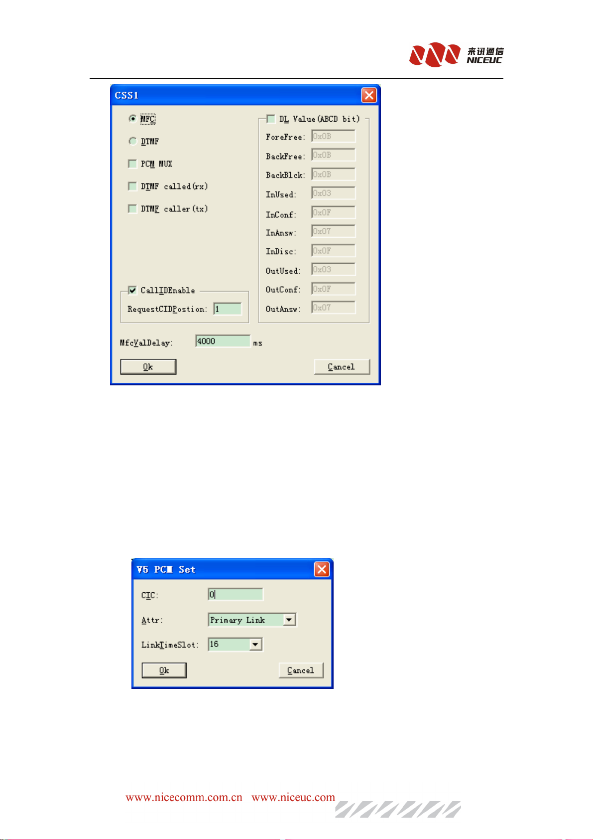
On the CSS1 sigaling parameters are as shows:
- 26 -
Page 27
NC-AD300E Manual
Device support MFC and DTMF two kinds of hair yards way. PCM multiplexing for
digital-analog conversion, the time slot channel line-one correspondence with the module,
which is equivalent analog line extension through E1. The default settings are usually able to
successfully connect, if client requests are special, according to manually specify the DL
value.
V5.2 signaling parameters are as follows:
CIC: identity V5 within the PCM-link a logical sequence of numbers, both sides must be
consistent.
Attr: to specify the primary link, 2nd link or no link.
Link time slot: designated which time slot is C-channel. When you select no link, unused
- 27 -
Page 28
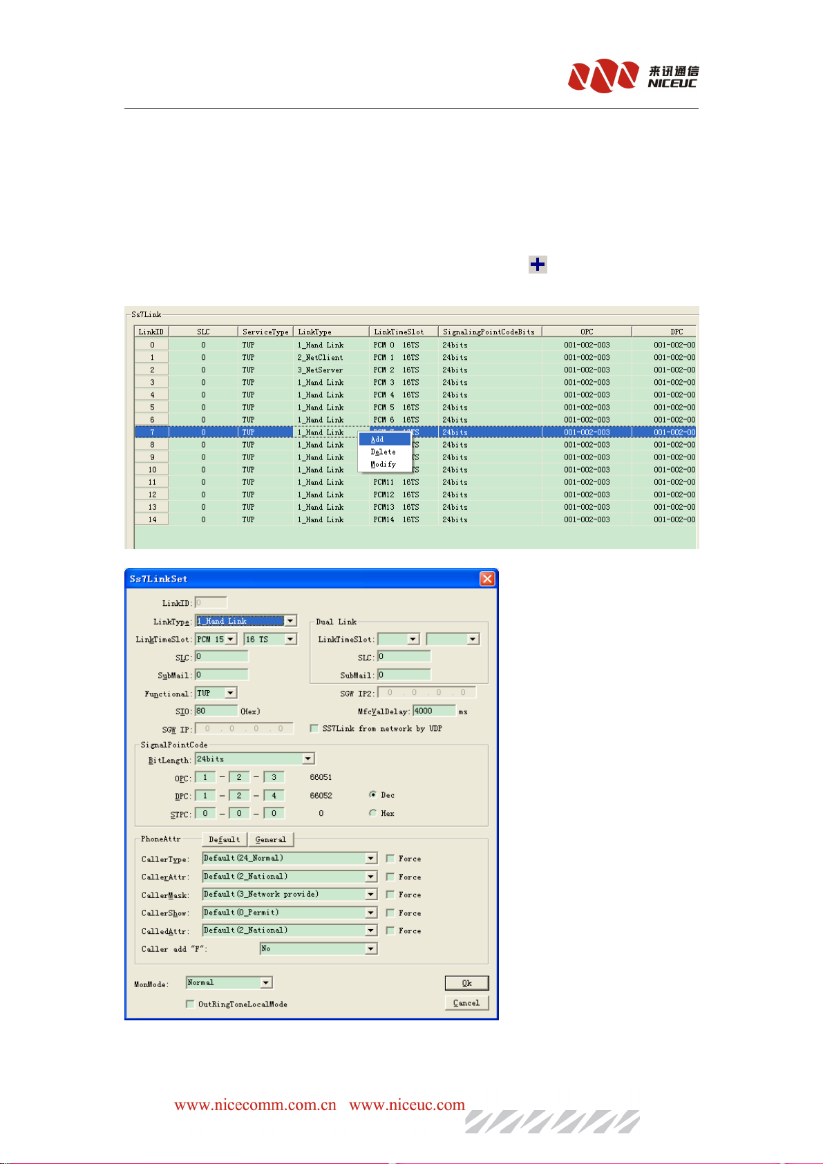
NC-AD300E Manual
slots can be blocked.
After completion of editing, write to ROM, restart the device for effective.
5.2.4.3 SS7 Signaling
For use of signaling SS7, you must first add the link parameter. In Index area select SS7
signaling, right click mouse button to add a new SS7 link in Parameter area.
This Can also be done in the "Data" menu, select "Add", or click on the toolbar Button to
add a link. Once installed, then modify the parameters one by one.
Link ID, Internal index number for SS7.
- 28 -
Page 29
NC-AD300E Manual
Link Code (SLC), the logical link number, must be consistent with the SS7 equipment on other side.
Click to Edit.
Business types, currently supports two kinds of TUP and ISUP. Click to select.
Connection method, specify the link where to connect. Click to select.
No, that there is no link connection, this link is invalid.
Hand Link, the link is from E1.
Netclient,
NetServer, forward SS7 link data through Ethernet (service side).
NetworkServerAndClient,including "NetClient" and "netserver" for cascading multiple
devices
SGW, connection from the PCM link, and transfer it to network for secondary development.
Link time slot, which time slots have the SS7 link.
Signaling point code-bit length, specify the length of the signaling point codes. Usually 24-bit for
domestic and international use 14-bit.
Signaling point code, SS7 signaling code, in the format XXX-XXX-XXX.
Backup link slot, If use 2 SS7 link to back each other, time slot for the back SS7 link.(load sharing).
Caller category, caller attributes, caller screening, caller display, called attributes, specify the
number of attributes called the primary, usually select the default value.
get ss7 link
from SWGIP
MfcValdelay, if calling number is received by-bit, over this time the receiving will be finished.
Usage pattern: usually choose "normal mode." "Signaling Collection" and "high-impedance
recording" in and line monitoring of the use of high barrier from the need for external devices can
be collected signaling, monitoring recording.
When the check the "ring-back does not pass through", the device will provide their own ring back tone,
rather than pass through the next level.
After completion of editing, write to ROM, restart the device for effective.
5.2.4.4 V5.2 signaling
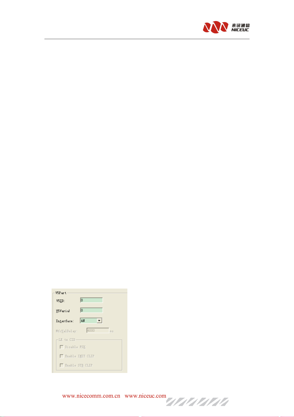
When using V5.2 signaling, the need to set the link parameters of V5. AD300E maximum support
One dirction , two links. Goes to "V5.2 signaling" and see belowparameters.
V5 variable and V5ID are the main parameters that must be consistent with the other side.
- 29 -
Page 30
NC-AD300E Manual
Interface type, designated as the AN side or LE side.
Access network AN is an abbreviation from the Service Node Interface (SNI) and the associated
user-network interface (UNI) between the number of transmission entities (such as the line facilities
and transmission facilities), is for the supply of telecommunications services to provide the necessary
carrying capacity the implementation of the system. An AN can be reused, exchange connectivity and
transport functional components.
LE is a local switch acronym, it’s a subscriber line through the AN terminating switches.
After completion of editing, write to ROM, restart the device for effective.
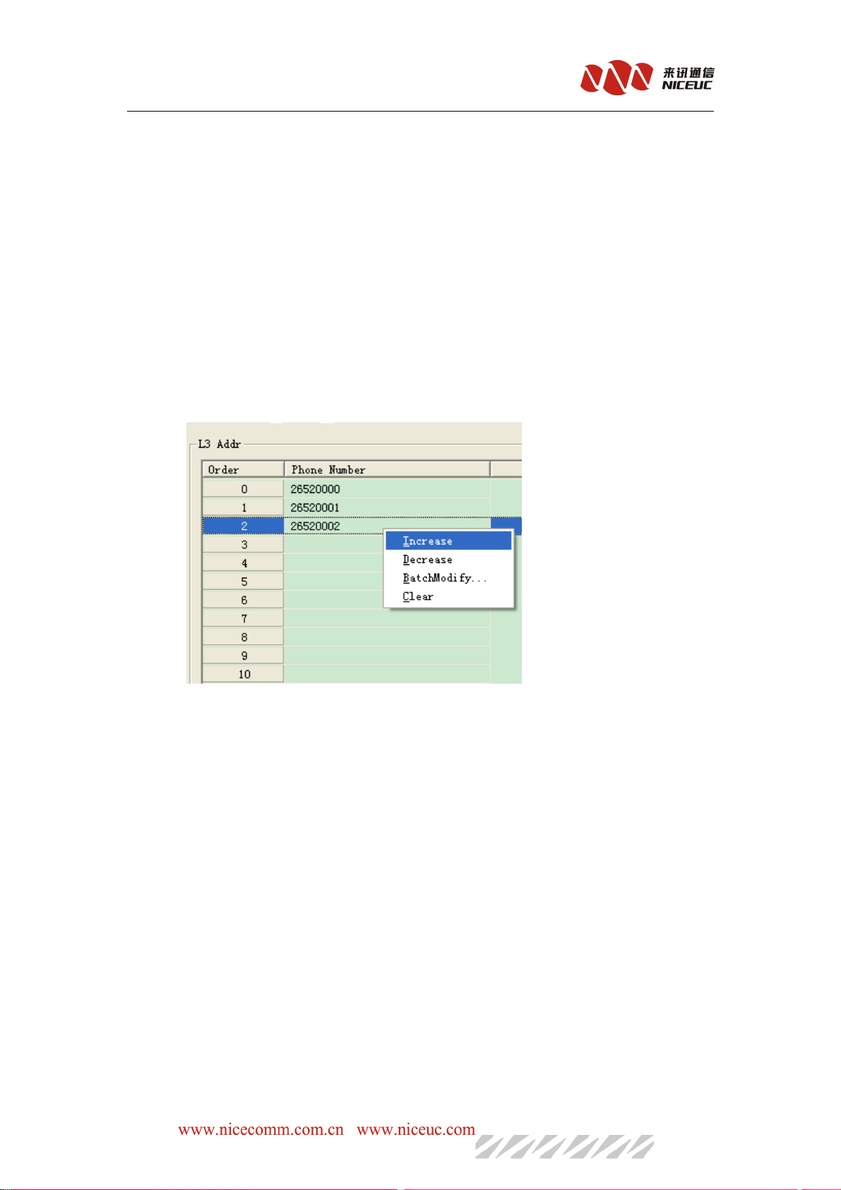
L3 address, is EFaddr types of PSTN signaling or control protocol message in the third layer of the
address. The aim is for the user port or public control functions provide a unique reference. Goes
to "L3 address" see below L3 address table.
One Phone number is corresponding to one address. In the "Phone Number" column on the
right-click pop-up menu can be "incremental", "decreasing" or "Batch Edit" number of the table.
After completion of editing, writing to ROM and RAM, can be effective immediately.
5.2.5 Analog Line Configuration
Analog circuits must be configured correctly, so user can make calls.
5.2.5.1 Line Type settings
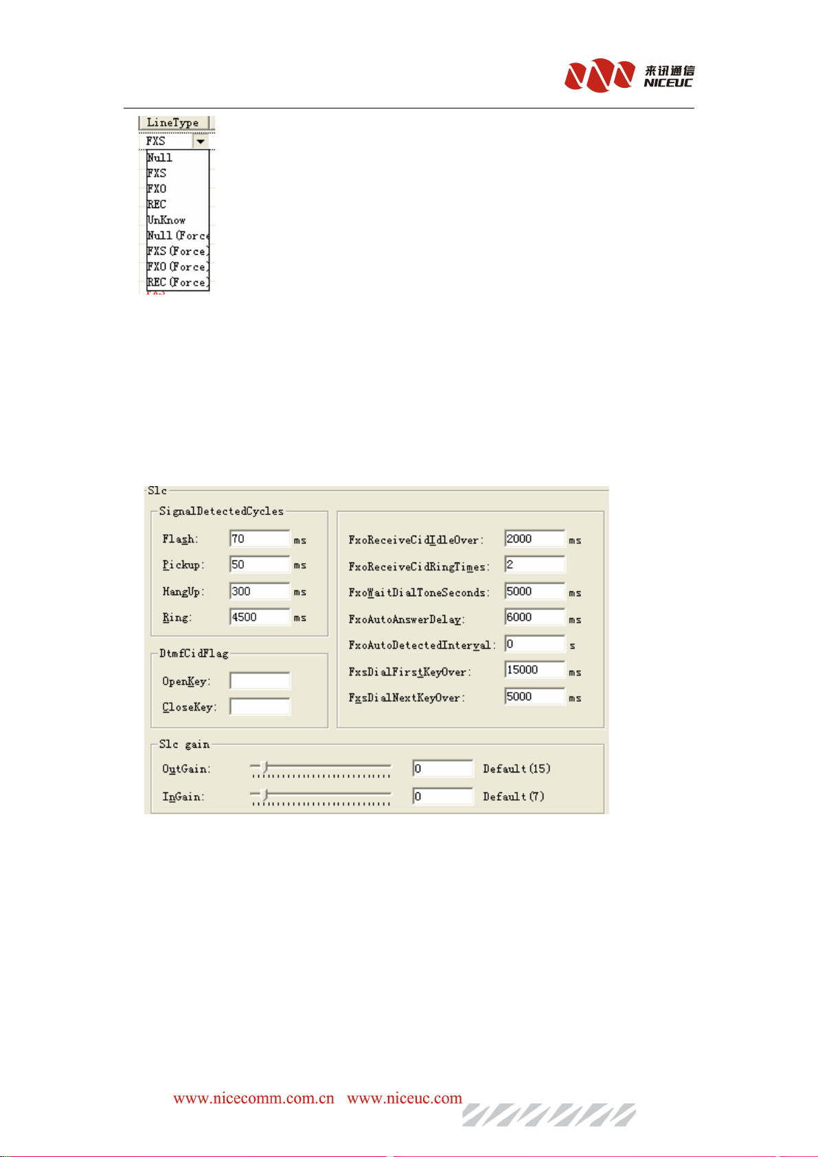
Analog circuit is divided into inner (FXS) and outside (FXO) two kinds. Select "analog line"
below the "line parameter" appears on the right analog line parameter table, in the Line Type
column, click in the pop-up list, select the correct type.
- 30 -
Page 31
NC-AD300E Manual
Device will automatically recognize the line module at startup. If automatically recognize
failed,select the right line type base on this selection menu.If you are using a Force type, such as
"FXS (forced)", it will not automatic recognize.
After completion of editing, write ROM, restart the device to take effect.
5.2.5.2 Analog Signal Set
Adjust the analog signal parameters can make equipment better adapt to the environment and
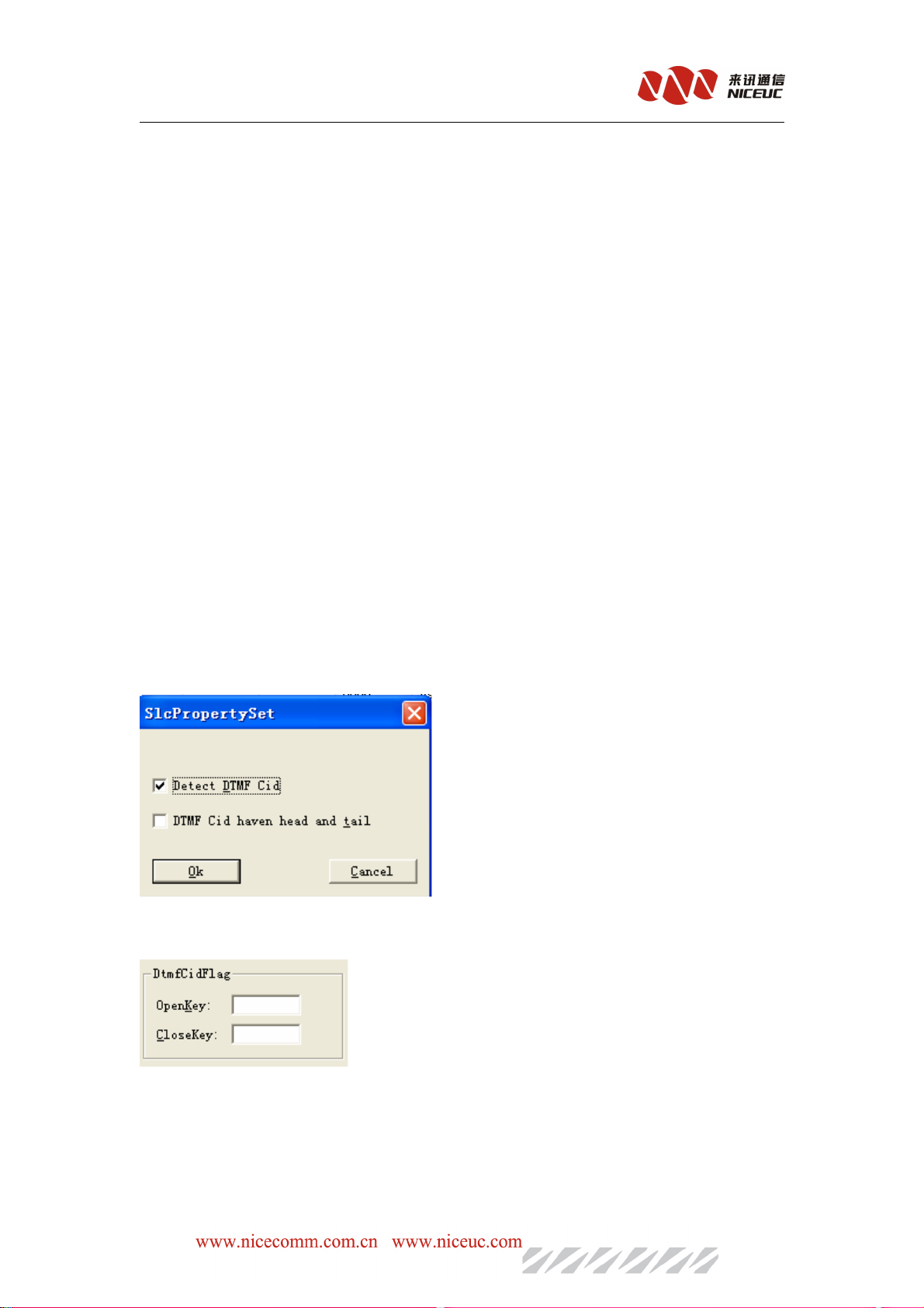
stableoperation. Goes to "SLC" in the Index area see the basic parameters as below:
In t
he part of SignalDetectedCycles: HangUp = 30 ms means that hook after 300 milliseconds the
line will be in the status of hanging up, pickup=50 ms means that after 50 ms that pick up the line
status will be pick up. Flash=70ms means if the hook up time is larger than 70ms and
300ms, the hook acation will cause the line status change to flash.
less than
Ring=4500ms means the ringing period is 4500 ms.
FxoReceivCidIdleOver: When call is incoming through analog trunk (FXO), the device will detect it
and receive Caller ID (CID). If the FXO ringing time over this time interval (which has become a
normal ringing) will be judged to have been finish the CID receiving. If less than or equal to 200
milliseconds will not detected FSK CID. Recommended value: 2000. fill the value of 0 will be the
default values: 2200.
FxoReceiveCidRingTimes:
If after FXO rings this value times but CID have not yet received,
- 31 -
Page 32
NC-AD300E Manual
the action will be stopped. Recommended value: 2, fill in 0 to take the default value: 2.
FxoWaitDialToneSeconds:
dial tone in order to call out. If more than 5000 milliseconds have not yet detected dial tone, then
stop to detection; If this value is less than 2000 milliseconds, don’t do dial tone detection, line will be
call out after the time value equal to FXOAutoAnswerDealy
FXOAutoAnswerDealy:when call out FXO, if this value is 0, indicating
signal is detected then connected, if it is (1 ~ 9), indicating a direct connect (not detect polarity reversal,
nor delay.); if equal or greater than 10, then the delay specified milliseconds to automatically connect.
For example, as here, fill in 6000, then delay 6000 milliseconds to connect.
FXOAutoDetectedInterval, you can set a long time to detect FXO lines, 0 means not detected.
FxsDialFirstKeyOver,if user pick up phone but no dial-up, after this vlue then the line will be busy.
Set to 0 will always wait no busy.
FxsDialNextKeyOver,if user pick up the phone and dial number, but more than this time no more
button pressed, then device think the dial-up has been completed. Set to 0 will be always waiting and
no time out
When the FxsDialFirstKeyOver and FxsDialNextKeyOver are set to 0 at the same time, AD300E
will not process and called number but directly route to the other side.
After completion of editing, write to ROM and RAM can be effective immediately.
When call out through analog trunk (FXO), you need to detect the
only
polarity reversal
5.2.5.3 Call Detection Settings
When the line type is FXO, you can specify whether you detect DTMF. If you do not detect
DTMF caller, the default detection is FSK. In Index area select "Line Part" goes to "LineProperty"
to see the table.
When you need to determine the beginning and end of DTMF call signs, in the "analog line"
parameter setting page as below:
Flag can only be one of the symbols in the "ABCD * #".
After completion of editing, write to ROM, restart the device to take effect.
5.2.5.4 Line Volume Set
- 32 -
Page 33

NC-AD300E Manual
In the "SLC" parameter page, you can set the circuit gain and attenuation
Move the slider to the right to increase volume, move to the left to decrease. OutGain corresponds
to the voice heared by other side, inGain corresponding to the volume of this side.
The “line Part”, you can set the volume for each line, such as:
After completion of editing, write to ROM and RAM to be effective immediately.
5.2.6 Call control
First need to group the same type of interface, as shown below:
Right click in the table, pop-up action menu, can add and delete.
menu operation. Or use the toolbar Button operation.
Once added, first select the "Line Type", then select line range (Note that the end value of
LineRange is excluded), at last select the rules for these LineType.
Rules including Length rules, number conversion rules and routing rules. Number conversion
rule can be applied to call in and call out. Each rule table can define multiple groups, each group there
are multiple rules.
User
Can also goes to "Data"
Note that the call in and call out is base on the AD300E itself
5.2.6.1 Length Rules
When the AD300E is receving the caller ID, we need to determine the length of each number. In
- 33 -
Page 34
NC-AD300E Manual
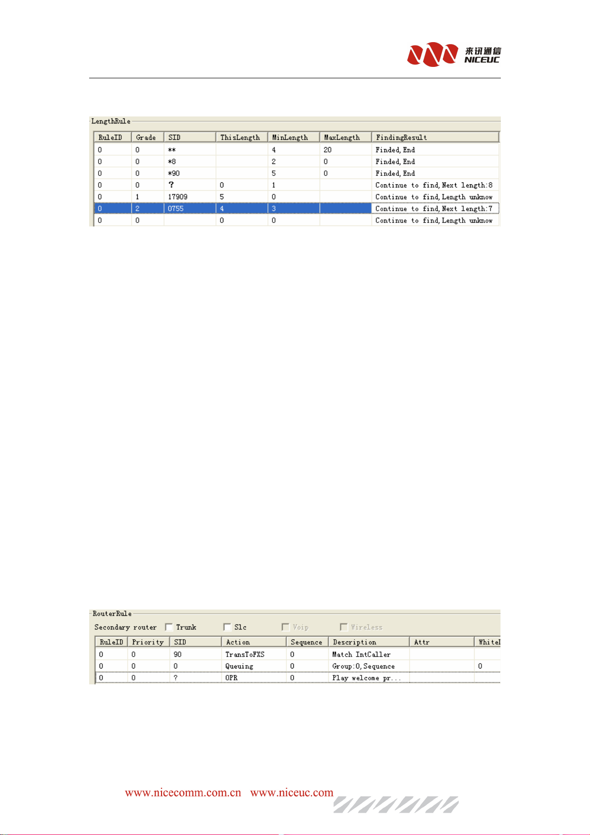
Index aera , select "SysPart->Rule->Length" will see the length table in the right, Use "Data" menu or
toolbar, or right-click menu, to add the length table.
The highest of number, matching conditions,“x”means NULL,none of the number can be
matched, “?” is wildcard, it means any number.
Length rule to serach the caller ID by devided it into sereral parts, maixma 8 parts. Fisrt to
match it with the smallest grade, if the "FindingResult" is "Finded, End", then the search stop,
otherwise, to subtract ThisLength for alreading found, and continue searching for next part. If you
can not find match for the next part, then number will be the "default length of the follow-up," or
serch failed if this value not be set.
See figure above configuration, for example, in RuleID 0, when called number is
17909075526520000 then search process is as follows: First, check rules in grade 0, SID = ? (SID
=surfix of caller ID), ? = all numbers), "The length" is 0, and FindResult is Continued to Find,
Next Length = 8, then keep searching in grade 1, in grade 1 there is a rule SID = 17909, match
with this caller ID, "ThisLength" = 5, and FindingResult is “Continue to Find, Length unknown”,
so thisLength will be cut, the number will change to 075526520000, and we keep searchingi n
Grade 2, SID = 0755 to match with the number.
5.2.6.2 Routing Rule
In Index area, select "SysPart->Rules->router" to see the router table, Use "Data" menu or
toolbar, or right-click menu, to add and delete the table.
The following for a detailed description of each parameter:
RuleID, specify which group belongs to the routing rules.
- 34 -
Page 35
NC-AD300E Manual
Priority, specify the priority of routing rules, will be related to the priority of analog circuit
parameters in the SLC->Line Part table.
SID, the Prefix of the calling number. The conditions to make judgement.
Sequence, the action will be followed from the sequence small to large, so when the small sequence
failed, route can goes to larger number sequence, thus can back up for multi routes.
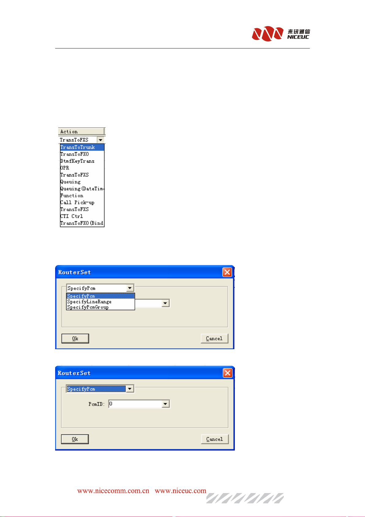
Action, specify how to handle the call. There are several options below:
1.
Switch to digital trunk
To forward calls to E1 trunking. The PCM time slot will be used for the call is decided by
the selection in description. There are three options to choose from.
1)Specify PCM, as shown below:
PCM ID is the E1 that you want to select.
- 35 -
Page 36
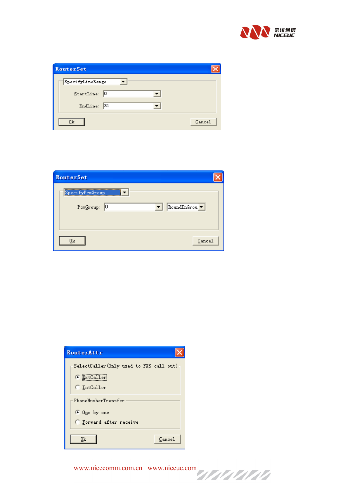
2) specify Line Range, as shown below:
Select
PCM time slot from start to the end, note that for PCM0, the number of time slot is
from 0 to 31, for PCM1 is from 32 to 63, and so on.
3), specify the PCM group, as shown below:
NC-AD300E Manual
In the PCM group you can select round in group or sequence in the group,
RoundInGroup, each time when call in will select the timeslot one by one from beginning to
the end.
SequenceInGroup, always selct the timeslot from the beginning for each time call in. only
busy to select the next one.
Members of group will be configured in the “Route->Group-> PCM”.
In the Attr column will configure the caller ID forward mode, bit-forward or one timeforward.
When using FXS to call out, you can specify the outbound Caller ID use"extension number" or "Direct
numbers."
- 36 -
Page 37
2.
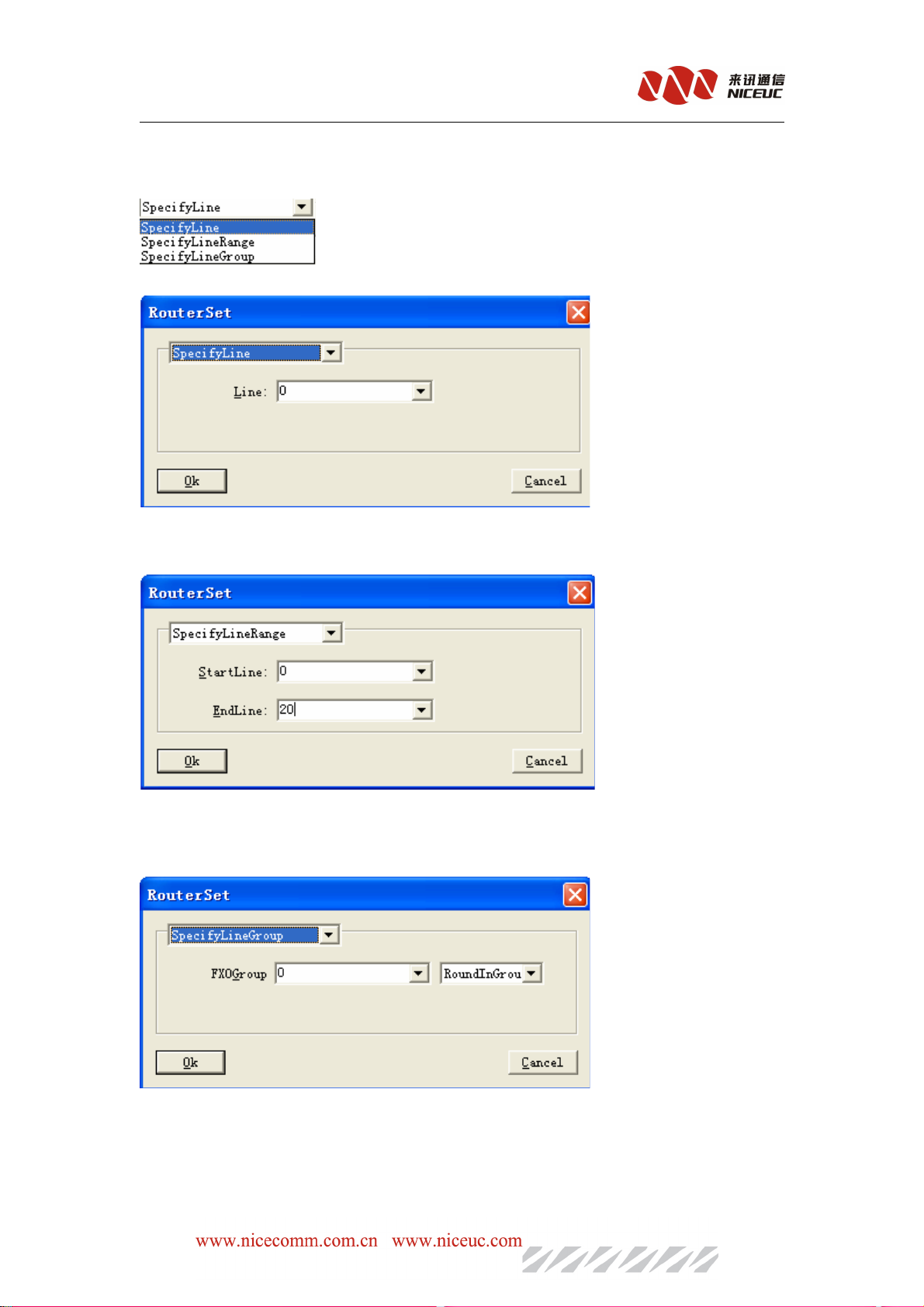
Transfer to FXO
To forward calls to FXO.
Description, There are three to choose from, as below figure:
frist SpecifyLine, as shown below:
Designate a FXO line
Second, specifyLineRange, as shown below:
The FXo
Trunk number will be used is decided by the selction in
NC-AD300E Manual
Specify a range, input the start number and end number of FXO lines
third, SpecifyLineGroups, as shown below:
The designated group of FXO, and the select of the lines in the group:
RoundInGroup: select the line one by one in turn, each time will select a different line.
SequenceInGroup, always selct the line from the beginning for each time call in. only busy
to select the next one.
- 37 -
Page 38
NC-AD300E Manual
Members of group will be configured in the “Route->Group-> FXO”.
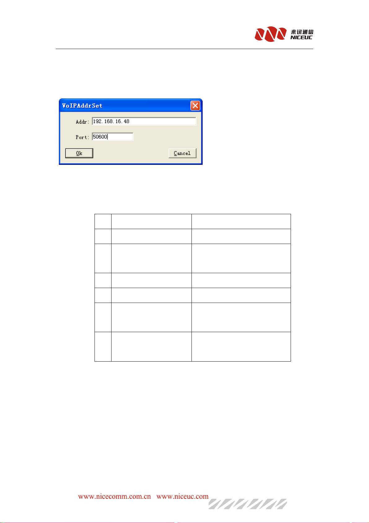
3. Transfer to
To forward calls to ,and click “RouterRule Description” list ,then you can configure it
Fill address and port .click “OK”.address: can be IPV4 or domain
4.Auto attendant
AD300E provides a simple Auto attendant process. Including six response voice as below
NO.
NO. Tip
Tip of
of the
the contents
NO.NO.
TipTip
ofof
contents Example
thethe
contentscontents
Example
ExampleExample
1 Welcome Tips “Welcome to XXX company
2 Operation Tips “Please dial extension
Number,dial zero for help”
3 Busy Tips “user is busy now
4 No answer Tips “Nobody answer the call now
5 No number Tips “The number you call doesn’t
exist”
6 Dial extension failed
Tips
When a call comes in, the Auto attendant play the first voice, then plays the second, waiting
for the user to press key, and then according to the key to play different voice. In column of description,
click to pop-up dialog box for key operational definition.
“Please call later or change
other numbers”
- 38 -
Page 39
NC-AD300E Manual
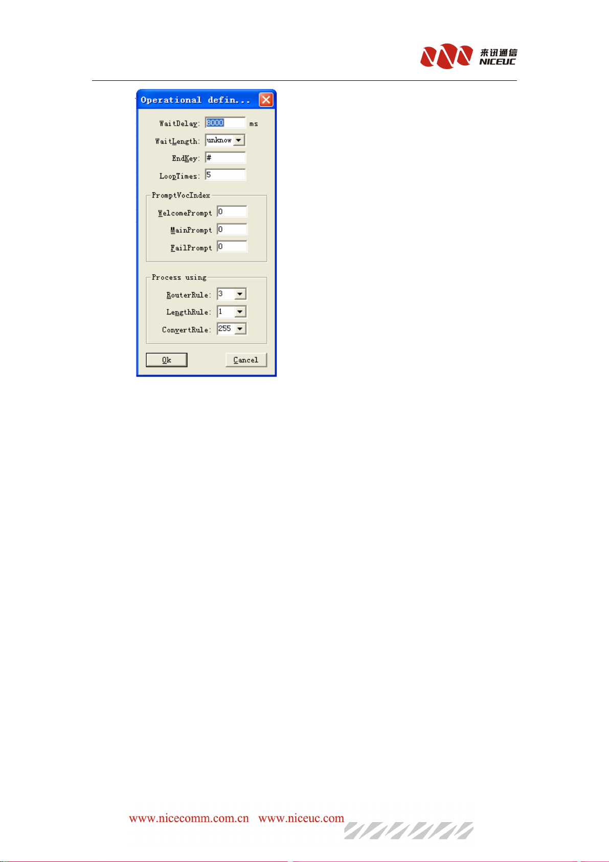
"WaitDelay" is used to set the timeout to receive the button, if more than this time no button
pressed, will stop waitting.
"WaitLength", if set to "unknown", according to the definition in "Process using” to deal with;
otherwise, according to the selection length to do treatment; proposals set to "unknown".
"End Key" to specify which key to press is the end of numbers, usually set to "#."
"LoopTimes" designated number of times the playback voice prompts. If more than this number,
still no button pressed, then the call will be terminated.
“PromptVocIndex”designate the welcome prompt tune, main instruction tune and fail prompt tune
voice index.if you fill out”0”.use the default voice.
“Process using” designates the follow up call process after the selection key pressed
Tips:More than one route can be configured out of a simple nested multi-level menus Process
1)Secondary
1)Secondary Dial-up
1)Secondary1)Secondary
Dial-up
Dial-upDial-up
。。。。
play dial tone to prompt the user to re-dial.It is the same to the “turn computer operator”
function, the only problem is that it playdial tone only one time,while “turn computer operator”
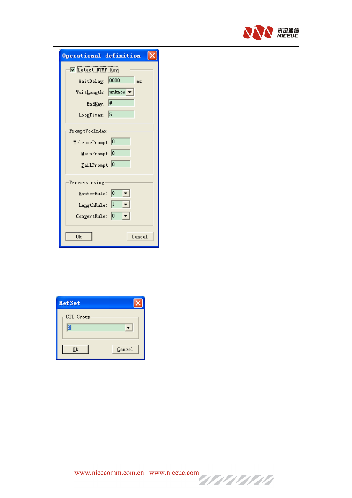
can play back recorded voice. Routing content to set operational definitions, as follows:
- 39 -
Page 40
NC-AD300E Manual
the parameter is the same with the "turn the computer operator" parameter.no more detaile
description
2)CTI
2)CTI Control
2)CTI2)CTI
Control
ControlControl
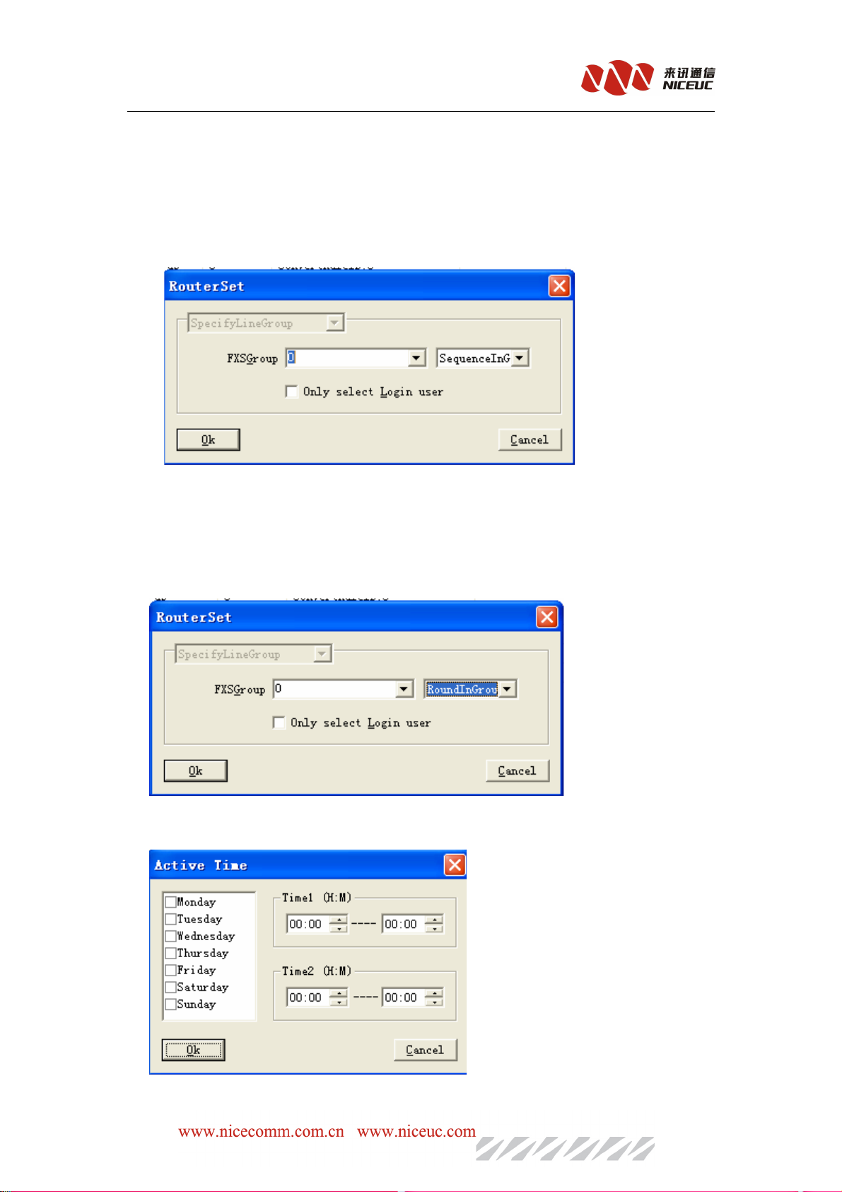
Calls can be transferred to the CTI program to control,CTI group parameters as a logo
Parameter. It will be sent to the CTI program interface
3)SWitch
3)SWitch to
3)SWitch3)SWitch
to digital
digital Trunk
toto
digitaldigital
Trunk((((Transmitted
TrunkTrunk
Transmitted by
TransmittedTransmitted
by the
the virtual
byby
thethe
virtual caller
virtualvirtual
caller))))
callercaller
The basic function is the same to “switch to digital trunk”, But it will follow the virtual caller
ID to select the channel line.
4)Transfer to FXS
- 40 -
Page 41
NC-AD300E Manual
Call will be transferred to the FXS, there are 2 ways to match the extensionnumber, one is
“Matching IntCaller”, the other is “Matching ExtCaller”, clickmouse button in “Description area”
to change these 2 options.
5 Queuing
When a call comes in, extension (FXS lines) will be ringing according to the order line one
by one. To set up the lines in the queue group, click “description” see below:
To set up a group, please goes to “SysPart->Rule->Router->Group->FXS
6. Queuing (datetime)
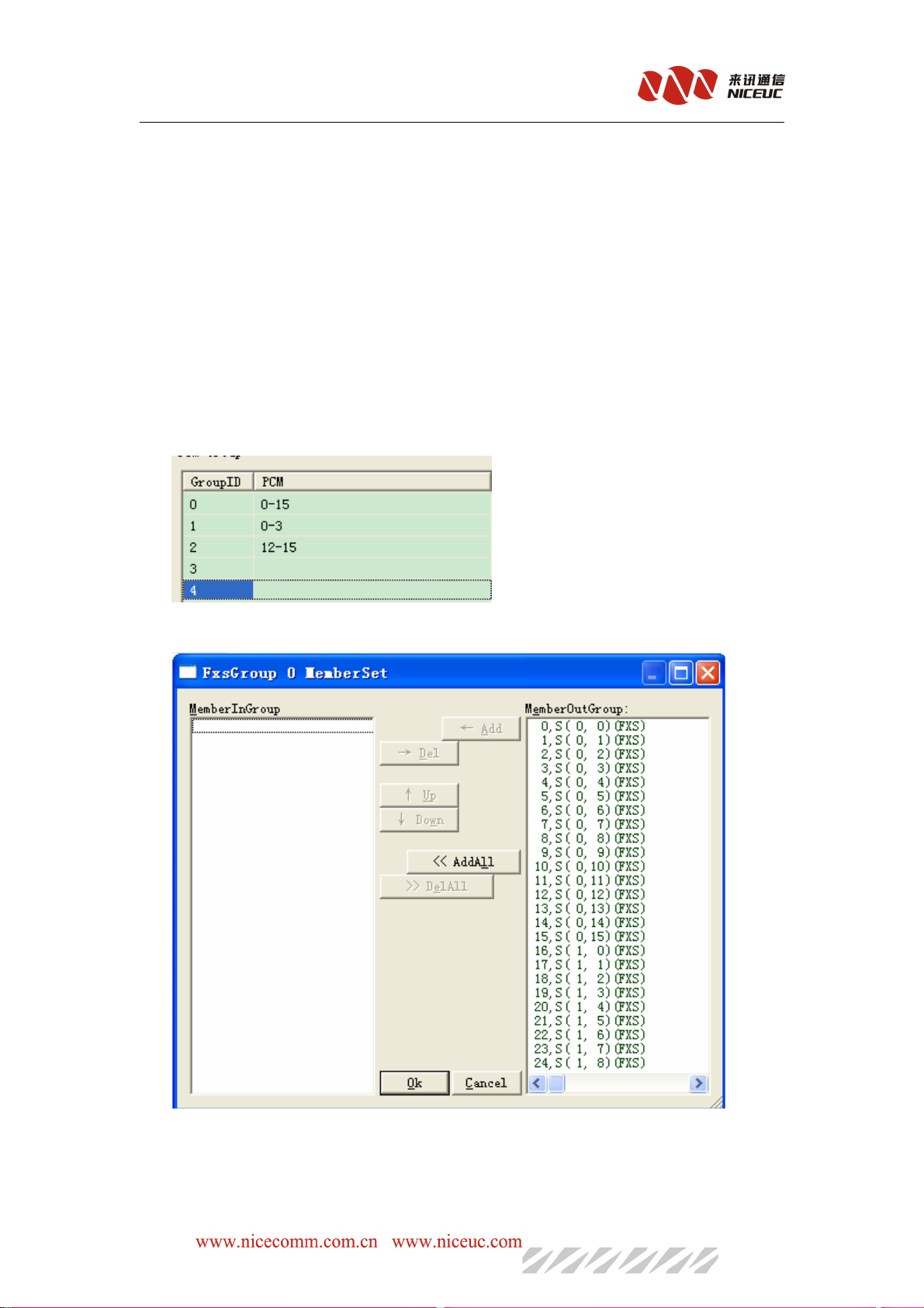
This action if for the set up of queuing function base on the working time.
In description to click as the same as in Queuing function
But in “Attr”, Click to see below interface for the time setting
- 41 -
Page 42
NC-AD300E Manual
For this can set up the active time of queuing functions.
7. Function
The definition of the specified phone keypad , usually set to "**". Through this functionkey, you
can set up the equipment through phone terminal, Detials See instructions attached 5.
8 Call Pick-up
Answer on behalf of the ringing extension by press defined function keys. Usually set to
"*8".
5.2.6.3 Groups
Goes to “SysPart->Rule->Router->group”, you can set up groups for PCM, FXS and FXO,
members in these groups will have the same properties.
PCM group, set the PCM of the grouping.
FXS group, set the grouping of subscriber lines.
Instructions: Group number is fixed, only need to add the lines or timeslot in that group.
- 42 -
Page 43
NC-AD300E Manual
5.3 Function Deployment
AD300E provides basic switch functions, also provide their own special features, and correctly
configured is required to make it work properly.
5.3.1 Ringback Tone settings
AD300E can customize their own personalized ringback tones. Operation is as follows:
1. AD300E convert audio files to use library files, steps see the attached 4.
2. Audio library file loaded into the device, the steps see attached 4.
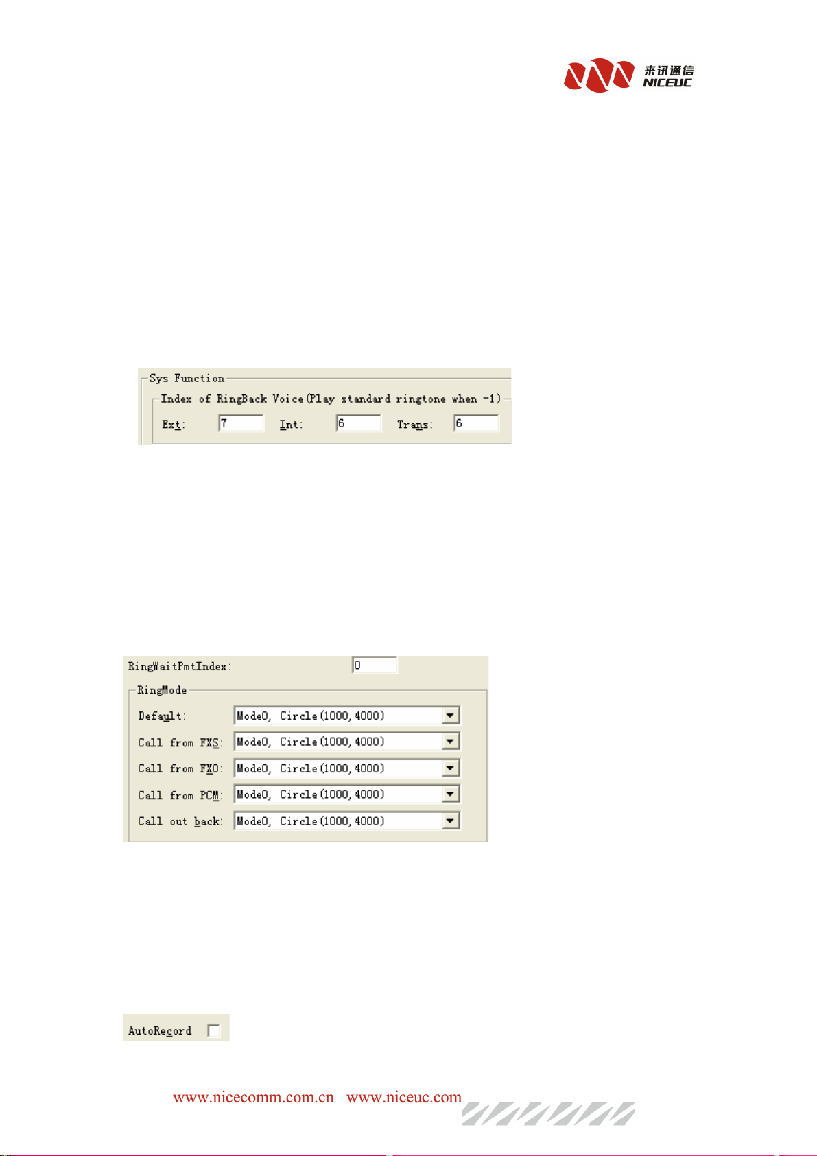
3. Using the configuration tool to modify the parameters.Goes to “SysPart->Sys Function” to
see below:
AD300E can specify three kinds of ringback tones. “Ext” means the ringback tone when call
from FXO, “Int”means ringback tone between extensions, “Trans” means ringback tone when
answer foract.
After completion of editing, writing to ROM and RAM, can be effective immediately.
5.3.2 Ring Duration time set
AD300E can specify a different method calls ringing circumstances. Goes to “SysPart->Sys
Function” to see below:
" Call out Back" means the system automatically calls the situation, and other undefined
conditions are by "default" processing.
After completion of editing, writing, ROM and RAM, can be effective immediately.
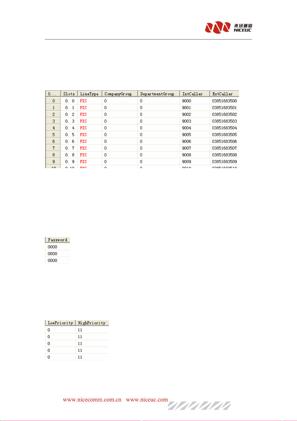
5.3.3 Automatic recording settings
AD300E can set to recording for all calls. Recording server software need to run in this case.
- 43 -
Page 44
NC-AD300E Manual
After completion of editing, writing to ROM and RAM, can be effective immediately.
5.3.4 Subsriber line Number Configuration
Goes to “LinePart->SLC->Line Part”
“ExtCaller”is the caller number for call out, “IntCaller”is the caller number for call between
extensions. Click to change the numbers. After completion of editing, writing to ROM and RAM,
can be effective immediately.
5.3.5 User Password Configuration
When using the phone instructions and desktop assistants password authentication is required.
Click to Edit, the password must be four of the numbers.
After completion of editing, writing to ROM and RAM can be effective immediately.
5.3.6 Call permissions
This can lock the extensions with different level of call permissions such as long distance call,
internation call
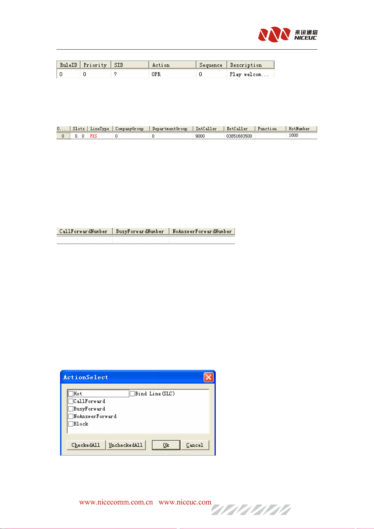
The higher the value the greater the access, if the line use HighPriority big than the value of call
routing access to all call routing.Then the call for this line will have high access.
- 44 -
Page 45
NC-AD300E Manual
This function is related to the value of priority in “SysPart->Router” as below:
5.3.7 Hot number
Subscriber Line For automatic call after picking up phones, you can use this feature.
For above configuration, extension number 9000 will dial hotnumber 1000 automaticly when pick
up this line.
After completion of editing, writing to ROM and RAM can be effective immediately.
5.3.8 Call Forward Settings
AD300E supports three kinds of call transfer, call forwarding, busy transfer and non-response
transfer.
“Call forwarding” is an unconditional call forwarding, any calls to this line will be automatically
transferred to the "call forwarding number".
“ BusyForwardNumber”, only when this line is busy call will be transferred to the
"BusyForwardNumber".
“NoAnswerForwardNumber”, only when no body answer the call then will be transferred to the
“NoAnswerForwardNumber”.
After completion of editing, writing to ROM and RAM can be effective immediately.
5.3.9 Do Not Disturb Setting
In the "function select" column, click to pop-up feature selection dialog:
Check the "Do Not Disturb," point "OK."
After completion of editing, writing to ROM and RAM can be effective immediately.
- 45 -
Page 46
NC-AD300E Manual
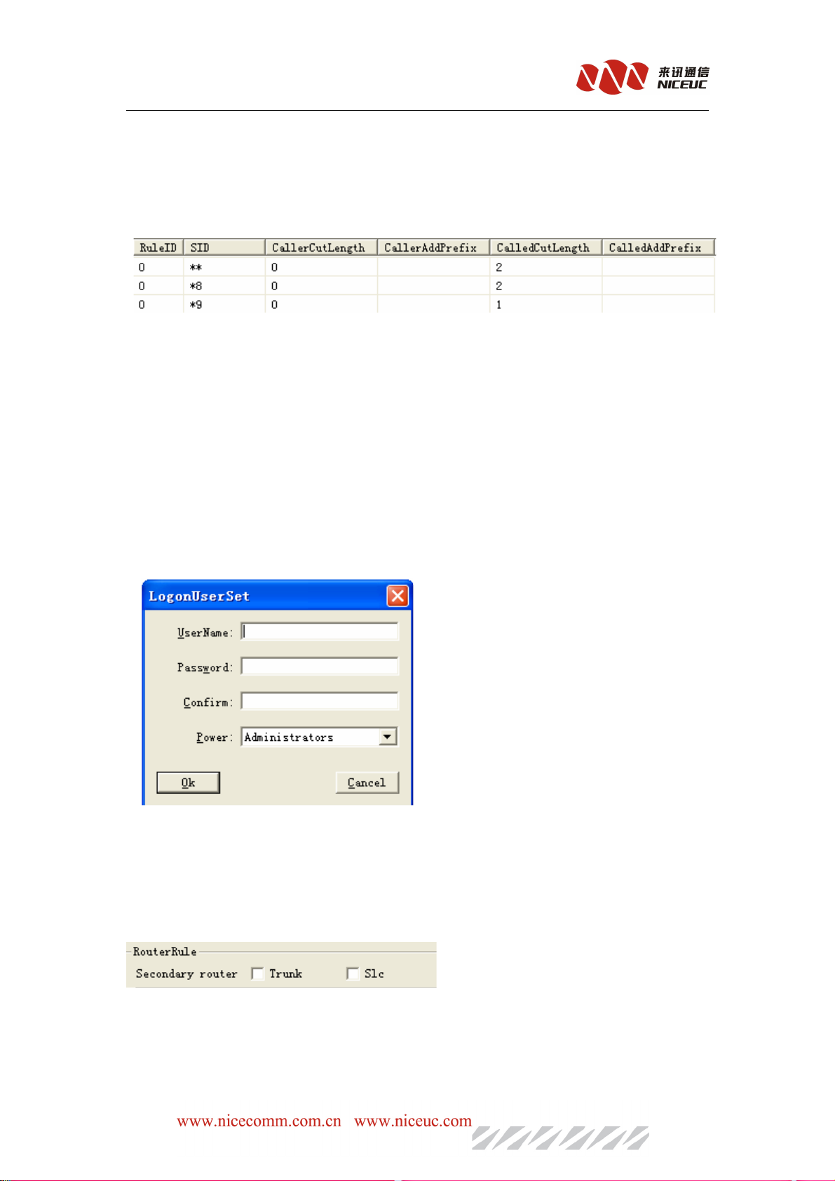
5.3.10 Number Convert
Goes to “SysPart->Rule->Convert” see below number convert tables:
"The word crown number" is the number at the beginning part of the rules dealing with the
conditions of the judge. Processing, are numbers in front of (prefix) to, delete or add a few
numbers. For example figure above the 0 group, the if the called number is 0 at the beginning,
then add 17909 in front.
After completion of editing, writing, ROM and RAM, can be effective immediately.
5.3.11 login account setting
Specify the telnet connection, authentication account, up to 10 accounts set up. The index in the
parameter area, select "login account" in the right side of the logon account management table.
Use "Data" menu or toolbar, or right-click menu, to add the delete operation.
After completion of editing, writing to ROM and RAM can be effective immediately.
5.3.12 Multi-routing backup
in the parameter area, select "routing rule" in the right setting parameters.
Select the appropriate line type, will enable the backup router for this line type, base on the rule
ID in router table.
- 46 -
Page 47
NC-AD300E Manual
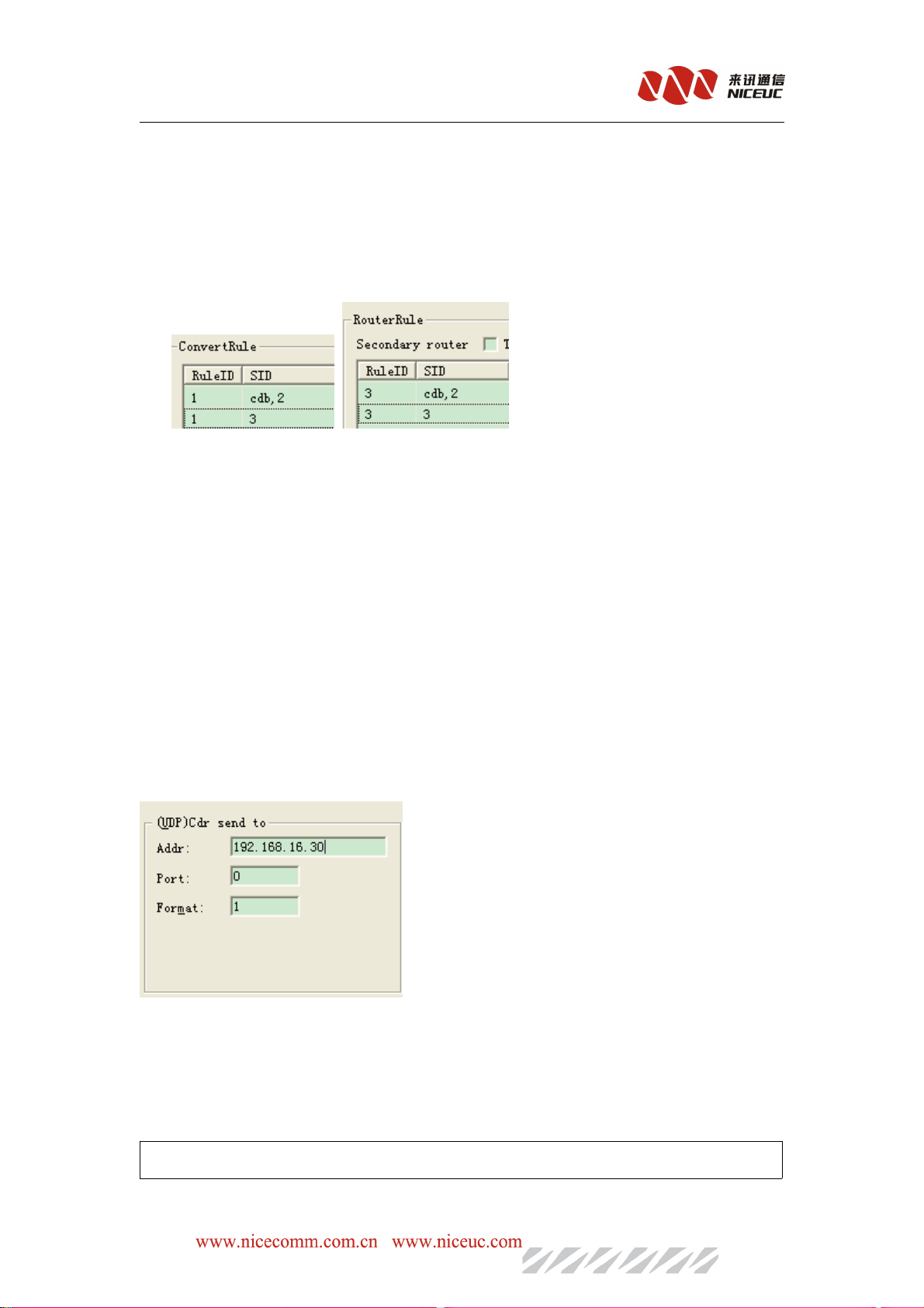
Every number correspondence a group number,and you can not only increase single,but also
batch. Click right menu operation,to support load numbers from the files.
After add CDB numbers, you can reference them in the routing and convert rule tables.
As frist , you must add a virtual rule that SID format is “cdb,xx” ,xx means character length,
If you want to match that figure above 8-bit word length of crown number,and then add the actual
number.
When device are searching crown number, if there have vitural rules, then it will
After completion of editing, write to ROM and RAM for effective.
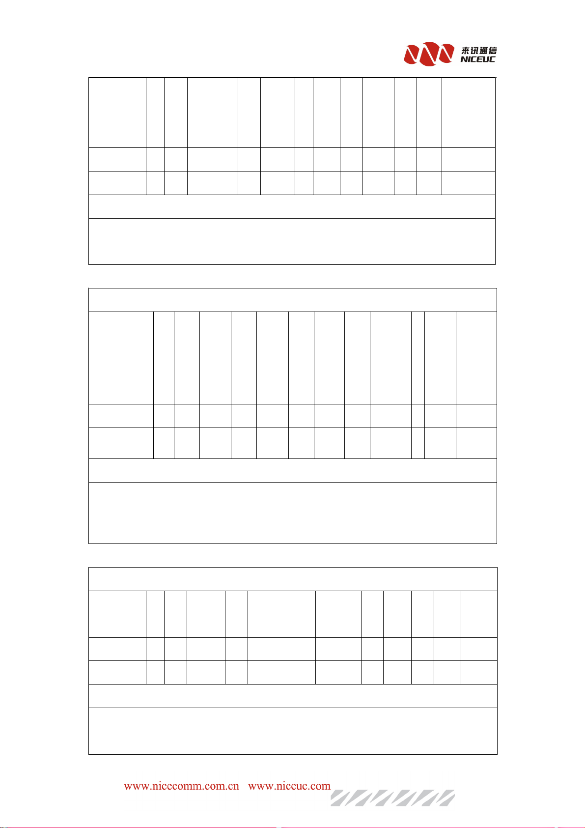
Chapter 6 Calling detail records
AD300E send out the CDR through net port.
For set up the destination of the CDR goes to “SysPart”
The original format of CDR is text strings, each one with "R" at the beginning and "\ r \ n" at the
end. With a space between each text string separated by fixed length, if the text string is not long
enough, will add the space to this fixed length, in the text string, there are four kinds of line types, 0 is
E1,1 is analog line, 2 is lines, 3 is wireless lines. Call duration is seconds.
There are three formate of CDR, 1, 2 and 101 which are shown below:
For receiving CDR, other software need to run.
Format 1
- 47 -
Page 48
String
String
StringString
logo
Outbound
line type
Inbound
line
type
caller
Called
number
NC-AD300E Manual
Talk
End
time
Length
Length
LengthLength
Description
Description
DescriptionDescription
1 1 1 1 1 1 15 1 20 1 5 2
R space space spae Left Space Left Space right “\r\n”
String Example: “R 0 1 88889010 98888 5”
The sample indicated that calls from analog lines to digital trunking, calling number is 88889010, the
called number is 98888, call duration is 5 seconds.
Format 2
String
String
StringString
Length
Length
LengthLength
Description
Description
DescriptionDescription
Out
bound
logo
Line
type
1 1 4 1 4 1 15 1 20 1 5 2
C Space space space left space left
In
bound
Line
type
caller
Called
number
Talk
time
空
right “\r\n”
格
End
String Example
:“C 0 1 1 18 88889010 98888 5”
Outbound lines and incoming line length is 4, the first one is line type, the latter three is the line
number.
The sample indicated that calls from analog lines number 18 to digital E1 timeslot 1, calling
number is 8888 9010, the called number is 98888, and call duration is 5 seconds.
Format 101
String
String
StringString
Length
Length
LengthLength
Description
Description
DescriptionDescription
String Example
Out bound
logo
line type
1 1 1 1 1 1 15 1 20 1 5 2
R space space space Left Space Left Space right “\r\n”
:“R 0 1 001 98888 5”
In bound
line type
Out bound
line NO.
Called
number
Talk
End
time
The sample indicated that calls from analog lines to E1, the called number is 98888, call duration is 5
seconds.
- 48 -
Page 49

Voice over UDP format is only an effective way.
If voice over TCP ,The format as fllows:
"\rCaaaa1,aaaa2,sssss,nnnnn,bbbb,cccc\n"
Beginning at”\r”. as the identity Character “C”
aaaa means : line number
ssss means :end_calling time
nnnn means: talk_duration
bbbb means:caller
cccc means:called number
the end : a carriage return “\n”
when we using “wcdrrx”,the format of CDR as fllows:
6.1 txt format
NC-AD300E Manual
CDR field as fllows:
CCCCaller,called
aller,called number,starttime,endtime,talk_duration,in_channel,out_channel.
aller,calledaller,called
The format of time :
year-month-day,hour:miniute:second.the
year-month-day,hour:miniute:second.the format
year-month-day,hour:miniute:second.theyear-month-day,hour:miniute:second.the
number,starttime,endtime,talk_duration,in_channel,out_channel.
number,starttime,endtime,talk_duration,in_channel,out_channel.number,starttime,endtime,talk_duration,in_channel,out_channel.
format of
formatformat
of channel:PCMID.slot
channel:PCMID.slot
ofof
channel:PCMID.slotchannel:PCMID.slot
6.2 Database format
Table name:cdr
Field Definitions:
Id type:int(10) unsigned,Not null, automatically increase,the primary Key
deviceid` type:smallint,Not null, default:0
in_channel`type:int(11) ,Not null,default : 0
out_channel`type:int(11) ,Not null, default :0
incomingtime`type:datetime,Not null ,default :'0000-00-00 00:00:00'
duration`type:int(10) unsigned,Not null ,default:0
caller`type:varchar(30),Not null,default:''
called`type:varchar(30),Not null,default:''
fail`type:tinyint(4),Not null,default :0
field means as follows:
ID,deviceID,in_channel,out_channel,incomingtime,talk_duration,caller,called,fail
- 49 -
Page 50

cdr.sql
Chapter 7. Debug monitor
7.1 Initialization Information
NC-AD300E Manual
During d
according to the device working condition. The following information is some commonly used
example for reference purposes only.
Now link status is speed: 100, duplex: FullDuplex
This line is the net port initialization information, device start-up will automatically detect the
speed of Ethernet, speed: 100 Mbps network, FullDuplex . If it is speed: 10, the network is 10 Mbps, If
network is not connected, you can not do automatically detection. The default speed is set to 100 Mbps
Network.
evice start-up there will be some initialization information, the information can be judged
dsp[0] dtmf06 load ok!
dsp[1] metrec load ok!]
This is a DSP chip initialization information, the format is "dsp [number] function description,
loaded situation." Number start from 0. Function including voice, dtmf mfc, metrec, conference,
callerid and so on. If load successful then "load ok", or else (like add [80]: 0x0! = 0xf073) means load
failed.
voc channels: 64
The number of voice processing resources available, one DSP has 64 channels.
voc read num: 6
number of
voc num: 6
voc [0] len: 17760
.........
After the success of voice-loaded, display the total number and size of each audio file, in bytes.
The following is a list PCM signaling
pcm [0] ss7 link [0], ts = 16
pcm [1] ss7 link [1], ts = 16
ss7 [0] mailnum: 1 ch (1,32) start ...
ss7 [1] mailnum: 1 ch (33,64) start ...
Here is information on STUN
set stun server = [: 3478]
The following is CtiLnk development interface server startup information
CtiLnk enter ...
automtic
Voice response resources have been loaded, -1 indicated that there is no voice.
- 50 -
Page 51

NC-AD300E Manual
CtiLnk tcp server enter ... lnk: 0 recv err
CtiLnk listen ... lnk: 1 recv err
Here are the voice recording and playing server from network startup information
VocCmd enter ...
NetVocRx run ...
VocCmd tcp server enter ...
VocCmd listen ..
Here is information on the network configuration server startup
NetCfg tcp server enter ...
NetCfg listen ...
NetCfg accept ...
McuTimer task spawn
Here is information on PCM synchronization
pcm: 0 sync: 0x3
pcm: 1 sync: 0x3
If the PCM synchronization loss will appear pcm: X sync: 0x3 or pcm: X sync: 0x1, success will
occur if the synchronization pcm: X sync: 0x0. Where X is the PCM number. If there pcm: X sync:
0x2, showing the alarming from opposite side.
7.2 Equipment Command
Common Command Description
OOOOrder
rder PPPParameters
rderrder
View
View basic
basic information
ViewView
basicbasic
ver
ver
verver
devinfo
devinfo
devinfodevinfo
pboot
pboot
pbootpboot
shsid
shsid
shsidshsid
sgmtime
sgmtime
sgmtimesgmtime
ipconfig
ipconfig
ipconfigipconfig
ifconfig
ifconfig
ifconfigifconfig
View resources
LineGrpShow
LineGrpShow
LineGrpShowLineGrpShow
CvTableShow
CvTableShow
CvTableShowCvTableShow
LenTableShow
LenTableShow
LenTableShowLenTableShow
RtTableShow
RtTableShow
RtTableShowRtTableShow
PcmAppShow
PcmAppShow
PcmAppShowPcmAppShow
Ss7AppShow
Ss7AppShow
Ss7AppShowSs7AppShow
VocSrcShow
VocSrcShow
VocSrcShowVocSrcShow
information
informationinformation
arameters Description
arametersarameters
The new IP address Read and modify new address
Modify sample“ifconfig “192.168.16.253:FFFFFF00””
PCM code View PCM parameters
Link ID View SS7 link parameters
Description
DescriptionDescription
Query the device software version
Read device information
See basic setting
Read Equipment Serial Number
Show Time
Read IP address
View call control table
View number convertion table
View number length rule table
View the routing rules table
View voice resources
Operations command
- 51 -
Page 52

cboot
cboot
cbootcboot
ldvoclib
ldvoclib
ldvoclibldvoclib
ldboot
ldboot
ldbootldboot
ldapp
ldapp
ldappldapp
chkapp
chkapp
chkappchkapp
settime
settime
settimesettime
setdate
setdate
setdatesetdate
reset
reset
resetreset
ChannelAlerting
ChannelAlerting
ChannelAlertingChannelAlerting
ChannelAnswer
ChannelAnswer
ChannelAnswerChannelAnswer
ChannelReleaseBy
ChannelReleaseBy
ChannelReleaseByChannelReleaseBy
ChannelAttrPrn
ChannelAttrPrn
ChannelAttrPrnChannelAttrPrn
NC-AD300E Manual
Modify basic setting
FTP connection mode
(0=active mode,1=passive mode)
FTP connection mode
(0=active mode,1=passive mode)
FTP connection
(0=active mode,1=passive mode)
FTPconnection mode
(0=active mode,1=passive mode)
Hours,minutes,seconds Set time
Year,month,day,hour,minute,
second
Line type,line number ,model Line reminder
Line type,line number ,model Line answer
Line type,line number,called
status
Line type,line number View detail property of lines
Add speech database
Update device Boot
Update device software
Calibration device software
Set date and time
Reset device
Release line
logNetEn
logNetEn
logNetEnlogNetEn
logNetDis
logNetDis
logNetDislogNetDis
logTerEn
logTerEn
logTerEnlogTerEn
logTerDis
logTerDis
logTerDislogTerDis
Debug
monpcm
monpcm
monpcmmonpcm
monpcms
monpcms
monpcmsmonpcms
monss7
monss7
monss7monss7
monss7s
monss7s
monss7smonss7s
setlapp
setlapp
setlappsetlapp
setlhdlc
setlhdlc
setlhdlcsetlhdlc
setlpri
setlpri
setlprisetlpri
setlss7
setlss7
setlss7setlss7
setlmtp2
setlmtp2
setlmtp2setlmtp2
setlusr
setlusr
setlusrsetlusr
setltab
setltab
setltabsetltab
Enable the Ethernet port to send
messages
Close net mouth send a message
Enable the serial port send a message
Close the serial port send a message
PCMID, switch (0 or 1) Monitor PCM
PCMID, number switch (0 or 1) PCM volume control
LinkID, switch (0 or 1) Monitoring on the SS7
LinkID, the number of
switches (0 or 1)
Trace levels (0 ~ 7) Global call tracking
Trace levels (0 ~ 7) Tracking HDLC imformation
Trace levels (0 ~ 7) Tracking PRI signaling
Trace levels (0 ~ 7) Tracking on the 7 th signaling
Trace levels (0 ~ 7) Signaling MTP2 part of the track on the 7th
Trace levels (0 ~ 7) Track analog line
Trace levels (0 ~ 7) Tracking call control look-up table
Volume control on the 7 th signaling
setlex
setlex
setlexsetlex
setlvoc
setlvoc
setlvocsetlvoc
Trace levels (0 ~ 7) Tracking the exchange of operation
Trace levels (0 ~ 7) Tracking voice operation
- 52 -
Page 53
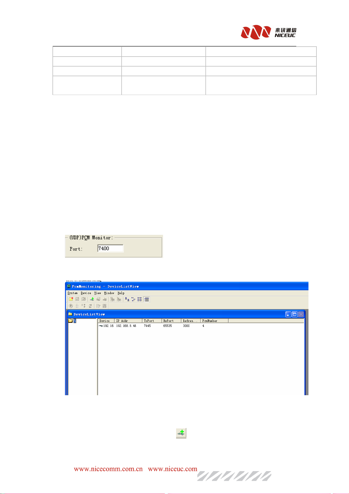
setlcdr
setlcdr
setlcdrsetlcdr
ErrorCode
ErrorCode
ErrorCodeErrorCode
ErrorHelp
ErrorHelp
ErrorHelpErrorHelp
Note that all of the commands are case-sensitive.
Trace levels (0 ~ 7) Track,then send the case
Mistake code See the error code information
7.3 calling trace
Using setlapp 7 command can track calling record .
7.4 E1 monitor
NC-AD300E Manual
Show trace levels of the detailed description
of
The small tools of NiceMonitor.exe
network connections. In the configuration tool interface, the parameters of the index area, select
"SysPart" in the right to see the UDP port.
7400 is commonly used.
Monitoring software interface is as follows:
is to
monitor the E1 status of AD300E. Monitor use UDP
NiceMonitor can monitor all of the equipment from Nice Communication which has E1 interfaces.
m
ultiple devices can be monitored, the port for each device must be set to different values.
Add your equipment, by click the shortcut of
, input the parameter of this device:
- 53 -
Page 54
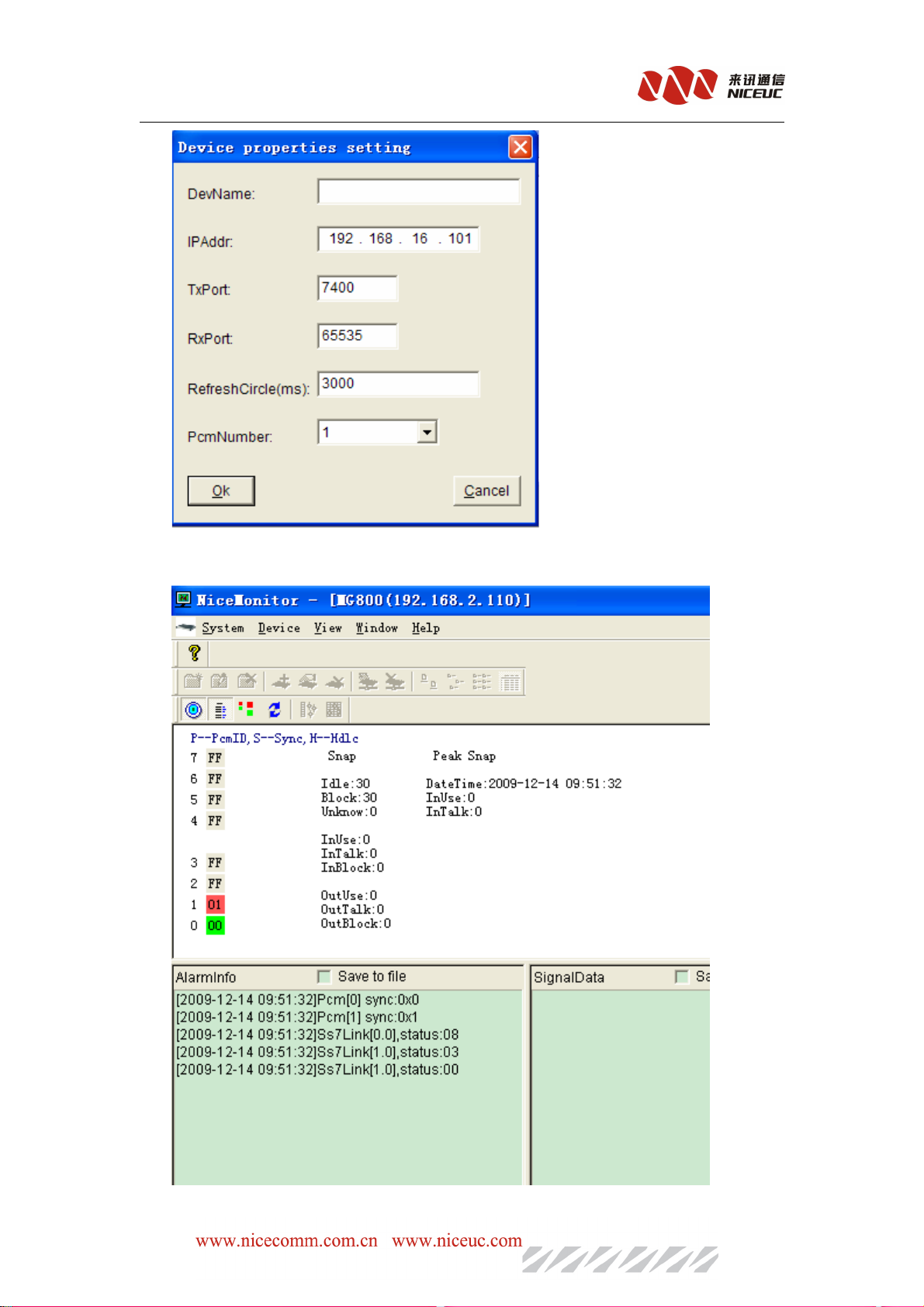
After finished, double-click to open control device. As shown
NC-AD300E Manual
- 54 -
Page 55

NC-AD300E Manual
Each E1 expressed by two square boxes, the red color means failure, the green color means
normal. The left boxes indicate the physical synchronization signal. The right box indicate the
HDLC link status. "Ss7Link" Here is the status of signaling links on SS7 signaling. Double-click
the sync box (left), you can open the current E1 channel state table. Double-click the link box
(right), you can open the link data tracking.
- 55 -
Page 56
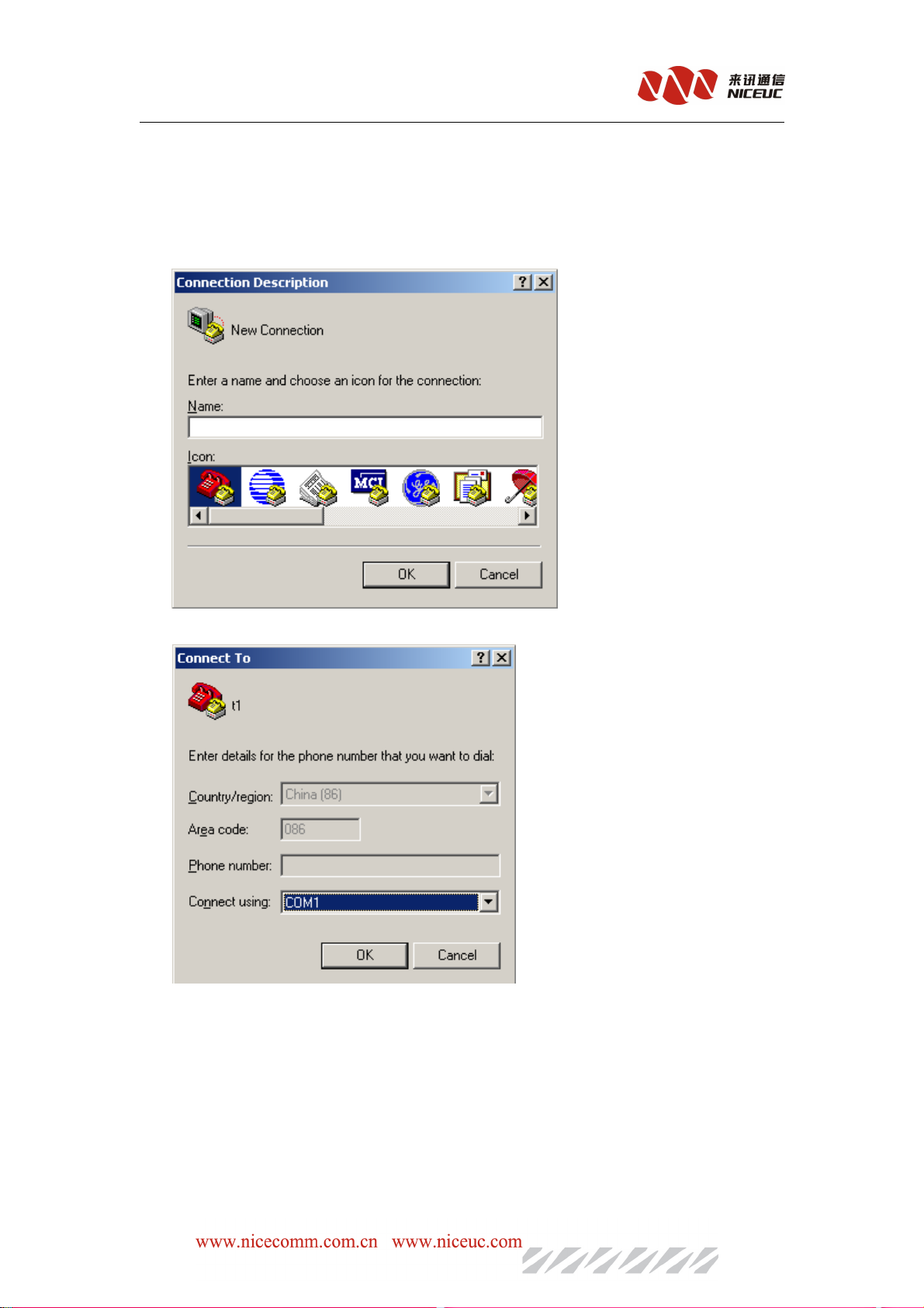
NC-AD300E Manual
Appendix 1. The use of Hyper Terminal
Create a hyperterminal, click "Start -" program - "Accessories -" Communication - "Hyper
Terminal" menu, pop-up "New Connection" wizard, fill in names as "HTCOM1-115200", then
select one your favorite icon.
Click "OK", a dialog box appears as follows:
Select the connected serial port, click "OK", pop-up properties interface of the Settings dialog
box.
- 56 -
Page 57
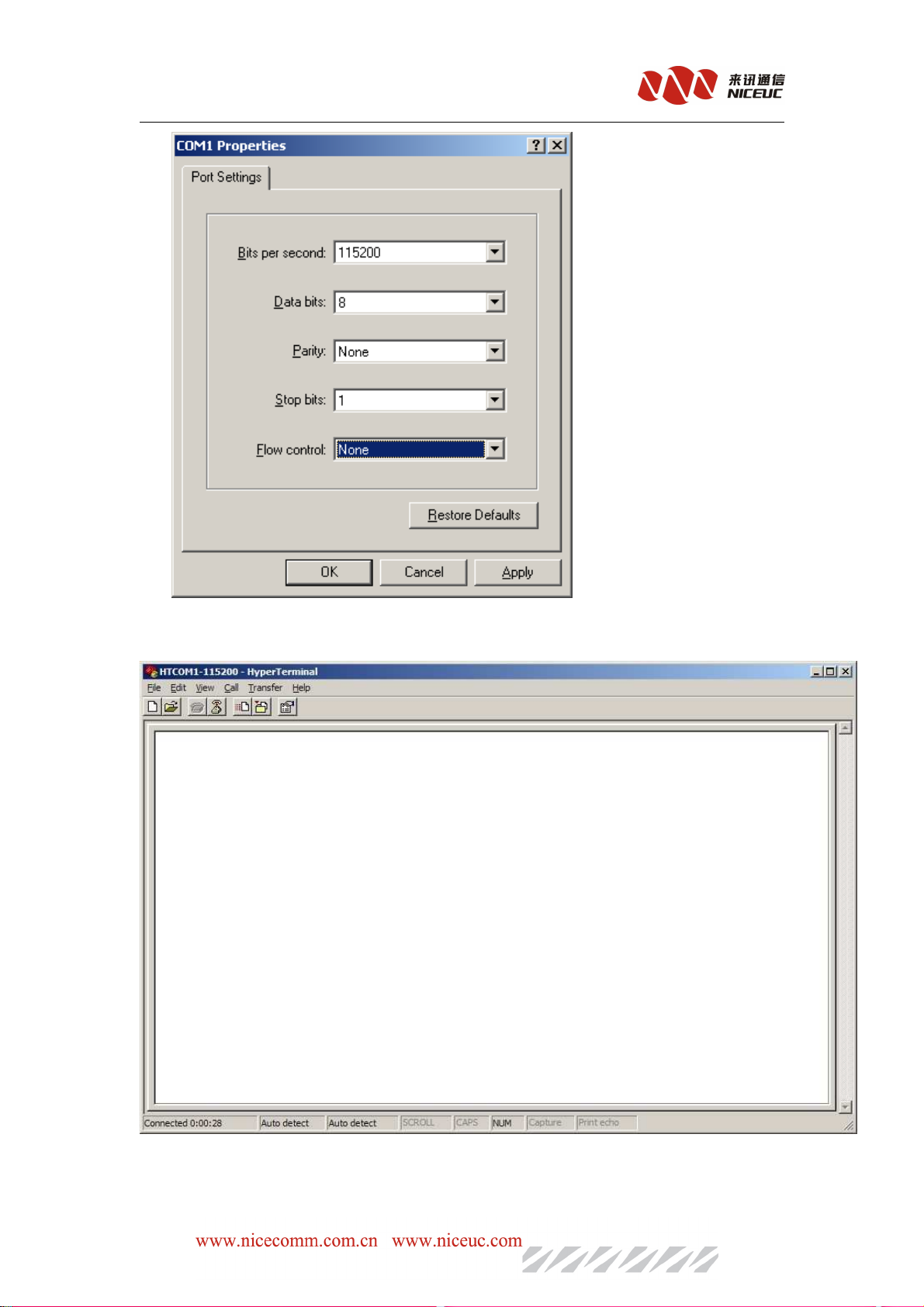
NC-AD300E Manual
Click "Restore Defaults", change the "bits per second" to 115200, then click "OK" appears
below thewindow.
This has been established, you can save it to your desktop for easy use next time. Click "File -"
Save As "menu can be saved to your desktop.
- 57 -
Page 58
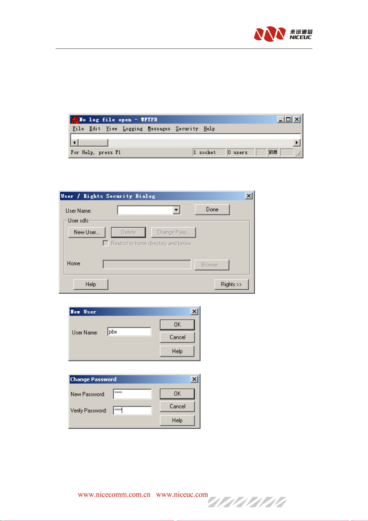
NC-AD300E Manual
Appendix 2. To establish FTP services
FTP is a file transfer protocol, when the device to download a file from your computer to use. If
the computer does not have FTP service program, you can use CD-ROM included with Wftpd32
software.
It is a small and easy to use FTP server program. After the interface is running as follows:
Next, create a new user:
Click "Security" menu, select "User / right ...", the following dialog box appears:
Click "New User ..." button, enter the user name, such as pbx, click "OK"
To enter a password, such as nice, click "OK",
In the Home (FTP services in the root directory), followed by the edit box enter a path, such as
"D: \Pbx", you can point "Browse ..." Browse to select the path.
- 58 -
Page 59
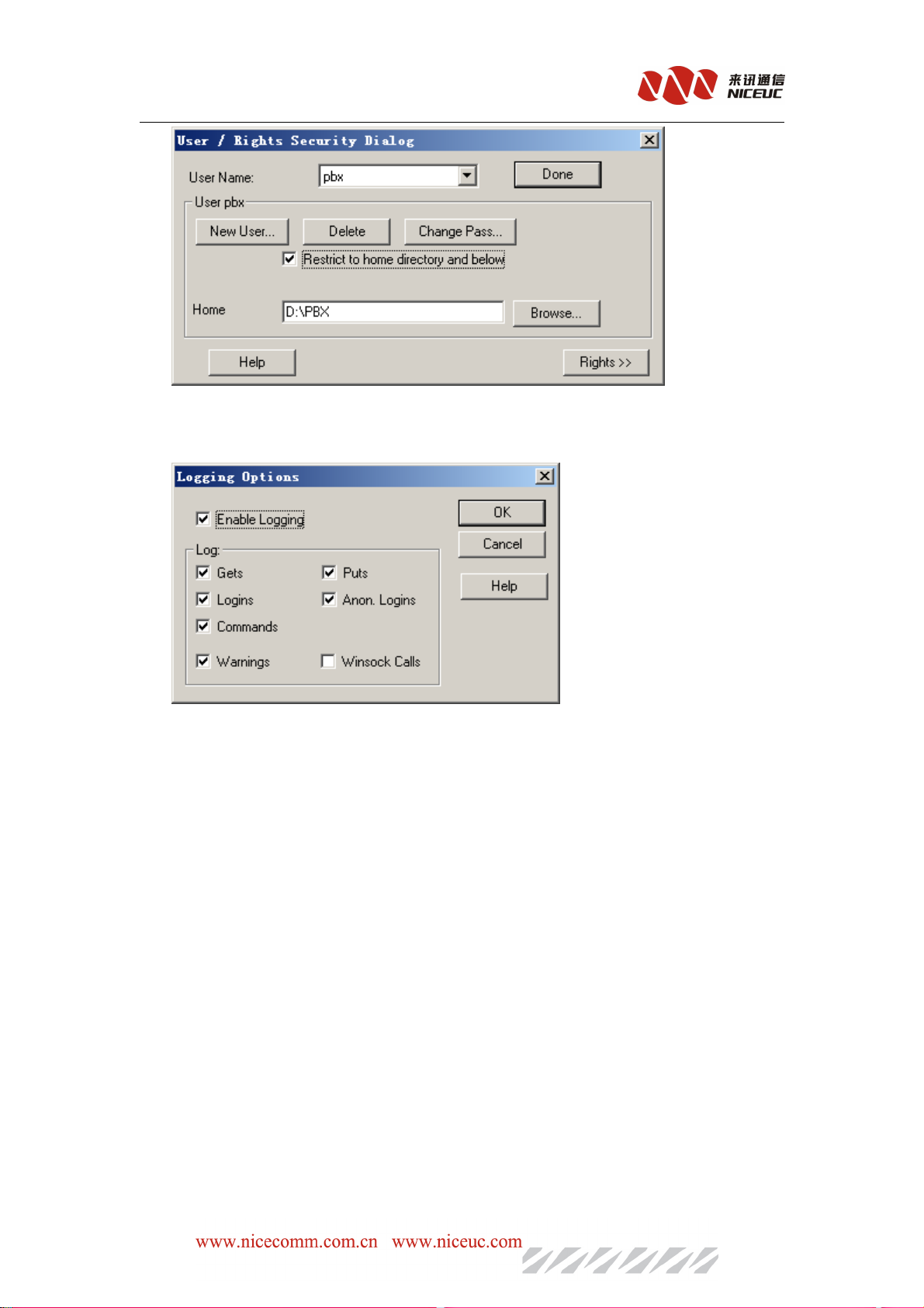
NC-AD300E Manual
Finally, click "Done" button to complete.
If you need to display the log, in the "Logging" menu, select "Log options", the pop-up
"Logging options" Settings dialog box.
Check the appropriate option, click "OK".
Appendix 3. Recording tone and load to PBX
You can use the recording software (such as Windows system with a tape recorder) to record
tone. Saved as a wav sound files, format must be used CCITT A-Law, 8kHz, 8 bit, mono, 7kb /
sec. After recording finished, use NiceVocMake.exe for formate transfer.
Run NiceVocMake.exe, interface is as follows.
- 59 -
Page 60
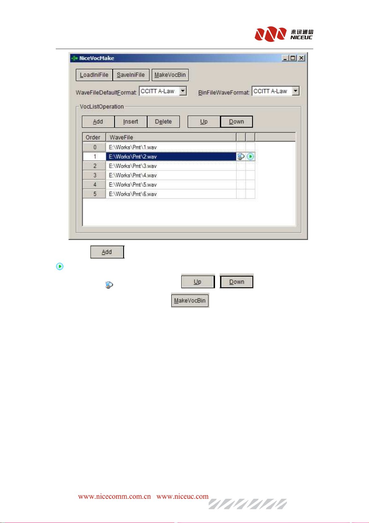
NC-AD300E Manual
Click " " button, will add the recorded wav file, select the added item, click
can play
the tone,and click can re-select the file, and , button can move the
positon of this tone up or down, Then click , to save these tone file into the BIN
file.
After the Bin file was made (usually 300evoc.bin), put it into the root directory of FTP accounts
In Running state of telnet, type the command: dwvoclib
Message show as follows:
Upload file of AD300E to FLASH!
Data in FLASH will be erased, continue? (Y/N)
EnterYto continue, typeNis
cancel.
HOST: server --->
here to enter the FTP hostIPIP address. The default is server,
which is the IP address in startup parameters.
USER:ad300e --->
PASSWORD: nice--->here
FILENAME: voclib.bin--->
Loading......
Received bytes:
......
here to enter the FTP account name.
here to
to enter
enter the
the FTP
FTP password,default
herehere
toto
enterenter
where the name of
thethe
password,default ::::nice
FTPFTP
password,defaultpassword,default
bin file
number of bytes shown here updated.
default
default :::: ad300e
defaultdefault
to be load .
ad300e。。。。
ad300ead300e
nice。。。。
nicenice
。。。。default
default :voclib
defaultdefault
:voclib.bin
:voclib:voclib
.bin。。。。
.bin.bin
After loading is complete, restart the equipment to be effect.
- 60 -
Page 61

NC-AD300E Manual
Appendix 4. Equipment software upgrades
Key
Key Code
Code Function
KeyKey
CodeCode
**00# Get line number
**01# Get line caller ID
**19*Old pwd *new pwd# Subscriber line to change password
**10*0 password# Unlock access (high-limit)
**10*1 password# Lock access (with a low limit)
**11*1# Set temporary Do not disturb (off-lock)
**11*0# Cancellation of the provisional don’t
Function Discription
FunctionFunction
disturb
Discription
DiscriptionDiscription
**12*1# Set do not disturb
**12*0# Cancel do not disturb
**13*SUB PHONE# Unconditional call forwarding
**13*0# Cancel unconditional call forwarding
**14*SUB PHONE# Busy transfer
**14*0# Cancel busy transfer
**15*SUB PHONE# No answer transfer
**15*0# Cancel No answer tranfer
**20*01# Objects to join the meeting
**20*01# Object to attend the meetings
**30*ID# Seat login in
**30# Cancel seat login
**40*# Delete all clock
**40*hhmm# Delete designed clock
**41*hhmm# Set once clock
**42*hhmm# Set premenant clock
**47*hhmmss# Set real-time clock
- 61 -
Page 62

NC-AD300E Manual
**48*yymmdd# Set year-month-day
**48*yymmddhhmmss# Set year-month-day-hour-miniute-second
**49*00# Select present time
**49*01# Select time(hhmmss)
**49*02# Select
**96# Device version ID
**97# Device
**98* new IP address# Set device address,the format is
XXX*XXX*XXX*XXX
**99# Attach device IP address
Appendix 5. Equipment software upgrades
Note: Be careful about software upgrade ,improper operation will cause the device not work.
Start the FTP service, put the file will be upgraded (usually Pbxe.bin) into the FTP root
directory. in running state, input the command ldapp to upgrade.
Message show as follows:Upload file of AD300E to FLASH!
Data in FLASH will be erased, continue? (Y/N)
HOST: server --->
here to enter the FTP host IP address. The default is server IP
address in startup parameters.
USER:ad300e --->
PASSWORD: nice--->Here
FILENAME: pbxe.bin--->
Loading......
Received bytes:
......
here to enter the FTP account name. The default is ad300e.
Here to
to enter
enter the
the FTP
HereHere
toto
enterenter
FTP password
thethe
FTPFTP
Enter to load the upgrade file name. The default is
number of bytes shown here updated.
Afterloading is complete successfully , restart the equipment to be effect.
In boot state, use command "u" to do upgrade.
In the [Boot]: prompt, enter "u", message show as follows:
boot device : at
unit number : 0
processor number : 0
host name : server
file name : pbxe.st
inet on ethernet (e) : 192.168.16.155:ffff0000
host inet (h) : 192.168.16.5
user (u) : ad300e
ftp password (pw) : nice
EnterYto continue, typeNis cancel.
password ,default
passwordpassword
,default :nice
,default,default
:nice
:nice:nice
pbx
pbxeeee.bin
.bin。。。。
pbxpbx
.bin.bin
- 62 -
Page 63

NC-AD300E Manual
flags (f) : 0x20
Attached TCP/IP interface to at0.
No link,set speed:100,duplex:FullDuplex
No link,set speed:100,duplex:FullDuplex
Attaching network interface lo0... done.
Begin to Load pbxe.bin
And then use the "x" command to start device can be.
Note: When you upgrade from the boot state, must first set boot parameters correctly.
Appendix6.SS7signaling messages introduction
ACB(Access barred signal)
ACC(Automatic congestion control information message)
ACM (Address complete message (note))
Note:ACM
Note:ACM including
Note:ACMNote:ACM
ADC(Address-complete, charge)
ADN(Address-complete, no charge)
ADX(Address-complete, coin box)
AFC(Address-complete, charge subscriber free)
AFN(Address-complete, no charge, subscriber free)
AFX(Address-complete, coin box, subscriber free)
ADI(Address incomplete signal)
ANC(Answer signal, charge)
ANN(Answer signal, no charge)
ANU(Answer signal, unqualified)(Temporarily use)
BLA(Blocking-acknowledgement signal)
BLO Blocking signal)
BSM(Backward set-up message)
CBK(Clear-back signal)
CCF(Continuity-failure signal)
CCL(Calling party clear signal)
CCM(Circuit supervision message)
CCR(Continuity-check-request signal)
CFL(Call-failure signal)
CGC(Circuit-group-congestion signal)
CHG(Charging message)(Temporarily use)
CLF(Clear-forward signal)
CNM(Circuit network management message group)
COT(Continuity signal)
CSM(Call supervision message)
DPN(Digital path not provided signal)
EUM(Extended unsuccessful backward set-up information message)
FAM(Forward address message)
including six
includingincluding
six kinds
sixsix
kinds of
kindskinds
of signaling
ofof
signaling
signalingsignaling
- 63 -
Page 64

NC-AD300E Manual
FOT(Forward-transfer signal)
FSM(Forward set-up message)
GRA(Circuit group reset-acknowledgement message)
GRM(Circuit group supervision messages)
GRQ(General request massage)
GRS(Circuit group reset message)
GSM(General forward set-up information message)
HBA(Hardware failure oriented group blocking-acknowledgement message)
HGB(Hardware failure oriented group blocking message)
HGU(Hardware failure oriented group unblocking message)
HUA(Hardware failure oriented group unblocking-acknowledgement message)
IAI(Initial address message with additional information)
IAM(Initial address message)
LOS(Line-out-of-service signal)
MAL(Malicious call identification signal)
MBA(Maintenance oriented group blocking-acknowledgement message)
MGB(Maintenance oriented group unblocking message)
MGU(Maintenance oriented group unblocking message)
MPM(Meter Pulse Message)
MUA(Maintenance oriented group unblocking-acknowledgement message)
NAM(National area message)
NCB(National call supervision message)
NNC(National-network-congestion signal)
NSB(National successful backward set-up message)
NUB(National unsuccessful backward set-up massage)
OPR(Operator signal)
RAN(Reanswer signal)
RLG(Release-guard signal)
RSC(Reset-circuit signal)
SAM(Subsequent address message)
SAO(Subsequent address message with one signal)
SBA(Software generated group blocking-acknowledgement message)
SBM(Successful backward set-up information message)
SEC(Switching-equipment-congestion signal)
SGB(Software generated group blocking message)
SGU(Software generated group unblocking message)
SLB(Subscriber Local busy signal)
SSB(Subscriber-busy signal (electrical))
SST(Send-special-information tone signal)
STB(Subscriber toll busy signal)
SUA(Software generated group unblocking-acknowledgement message)
UBA(Unblocking-acknowledgment message)
UBM(Unsuccessful backward set-up information message)
UNN(Unallocated-number signal)
- 64 -
 Loading...