


AVIO600
AVIO1000
Motorisation pour portes de garage
FR - Instructions et avertissements pour l’installation et l’utilisation
EN - Instructions and warnings for installation and use
IT - Istruzioni ed avvertenze per l’installazione e l’uso
PL - Instrukcje i ostrzeenia do instalacji i uytkoania

GENERAL SAFETY WARNINGS AND PRECAUTIONS (Instructions translated from Italian)
––– STEP 1 –––
CAUTION - Important safety instructions. Observe all the instructions as improper installation may cause serious damage
CAUTION - Important safety instructions. It is important to comply with these instructions to ensure personal safety. Store these
instructions
• Before commencing the installation, check the “Product technical
specifications”, in particular whether this product is suitable for automating your guided part. Should it be unsuitable, DO NOT proceed
with the installation
• The product cannot be used before it has been commissioned as
specified in the “Testing and commissioning” chapter
CAUTION - According to the most recent European legislation, the
implementation of an automation system must comply with the
harmonised standards set forth in the Machinery Directive in force,
which allow for declaring the presumed conformity of the automation. On account of this, all operations regarding connection
to the mains electricity, as well as product testing, commissioning and maintenance, must be performed exclusively by a qualified
and skilled technician!
• Before proceeding with the product’s installation, check that all materi-
als are in good working order and are suitable for the intended applications
• The product is not intended for use by persons (including children) with
reduced physical, sensory or mental capacities, nor by anyone lacking
sufficient experience or familiarity with the product
• Children must not play with the appliance
• Do not allow children to play with the control devices of the product.
Keep the remote controls out of reach of children
CAUTION - In order to avoid any danger from inadvertent resetting of the
thermal cut-off device, this appliance must not be powered through an external switching device, such as a timer, or connected to a supply that is
regularly powered or switched off by the circuit
• Provide a disconnection device (not supplied) in the plant’s mains power supply, with a contact opening distance that ensures complete disconnection under the conditions envisaged by Overvoltage Category III
• Handle the product with care during installation, taking care to avoid
crushing, knocks, falls or contact with liquids of any kind. Keep the
product away from sources of heat and open flames. Failure to observe the above can damage the product and increase the risk of danger or malfunctions. If this should happen, stop installation immediately
and contact the Customer Service
• The manufacturer assumes no liability for damage to property, items or
persons resulting from non-compliance with the assembly instructions.
In such cases the warranty does not cover material defects
• The weighted sound pressure level of the emission A is lower than 70
dB(A)
• Cleaning and maintenance to be carried out by the user must not be
effected by unsupervised children
• Before intervening on the system (maintenance, cleaning), always disconnect the product from the mains power supply
• Check the system periodically, in particular all cables, springs and supports to detect possible imbalances, signs of wear or damage. Do not
use if repairs or adjustments are necessary, because a failure with the
installation or an incorrectly balanced automated system may lead to
injury
• The packaging materials of the product must be disposed of in compliance with local regulations
• Keep persons away from the gate when it is moved through the control
elements
• When performing a manoeuvre, keep an eye on the automated mechanism and keep all bystanders at a safe distance until the movement
has been completed
• Do not operate the automation if anyone is working on it; disconnect
the power supply before permitting any work to be carried out
m from the ground and must not be accessible
• If the opening movement is controlled by a fire-prevention system,
make sure that any windows larger than 200 mm are closed by the
control elements
• Prevent and avoid any form of trapping between the moving and fixed
parts during manoeuvres
• Permanently affix the manual operation label next to the element enabling the manoeuvre itself
• After installing the drive motor, make sure that the mechanism, protective system and all manual manoeuvres operate properly
English
INSTALLATION PRECAUTIONS
• Prior to installing the drive motor, check that all mechanical compo-
nents are in good working order and properly balanced, and that the
automation moves correctly
• If the door being automated has a pedestrian door, the system must
include a control device inhibiting the operation of the motor when the
pedestrian door is open
• Make sure that the controls are kept at a safe distance from moving
parts, while allowing a good view of these.
• Unless a selector is used, the controls should be installed at least 1.5
English – 1

PRODUCT DESCRIPTION
––– STEP 2 –––
2.1 – APPLICATIONS
AVIO is a line of gearmotors designed for the automation of sectional
doors and the suitable GA2 accessory, not supplied, or overhead (springs
or counterweights) doors.
TABLE 1 - Comparison of main features of the AVIO gearmotors
Gearmotor type
Maximum torque (corresponding to the maximum force)
Max. No. of ECSBus units
English
Emergency power supply
Guide length
2.2 – DESCRIPTION OF THE AUTOMATION
To clarify a few terms and aspects of a sectional or overhead door automation system: in Figure 1 we provide an example of a typical AVIO600 or
AVIO1000 application:
1
Any applications other than those described above or in different
conditions from those specied in this manual are forbidden.
AVIO operates with electric power. In the event of a power failure, the
gearmotor can be released using a suitable cord in order to move the
door manually.
As an alternative, the optional accessory can be used on the AVIO1000
model: PR100 buffer battery.
AVIO600
10,8 Nm (600 N)
1
No
3x1m
A) FL200 ashing light ith incorporated aerial (optional)
B) Pair of PH200 photocells (optional)
C) Mechanical stops
D) GD102 or GD103 gearmotor
AVIO1000
18 Nm (1000 N)
6
with PR100
4x1m
A
B
2.3 – DESCRIPTION OF DEVICES
AVIO600 and AVIO1000 can be made-up of the devices shown in Fig. 2;
make immediately sure that they correspond to the contents of the package and verify the integrity of the devices.
TABLE 2 - Component and accessory list
Reference
a
b
c
d
e
f
g
h
AVIO600
1 GD102 electromechanical gearmotor with incorporated
control unit
1 3-metre guide with pre-assembled belt.
2 coupling proles
2 ceiling-mounted brackets
Miscellaneous small parts: screws, washers, etc. see tables
1, 2, 3 and 4 (*)
2 ECCO5... radio transmitters
PH200 pair of wall-mounted photocells
FL200 ashing light ith incorporated aerial
D
C
Note: to adapt AVIO600 and AVIO1000 to local regulations, the contents
of the package may vary; an exact list of the contents is shown on the
outside of the package. Anyhow, please consult the sales manager.
AVIO1000
1 GD103 electromechanical gearmotor with incorporated
control unit
1 4-metre guide with pre-assembled belt.
3 coupling proles
4 ceiling-mounted brackets
Miscellaneous small parts: screws, washers, etc. see tables 1,
2, 3 and 4 (*).
2 ECCO5... radio transmitters
PH200 pair of wall-mounted photocells
FL200 ashing light ith incorporated aerial
* The screws required for mounting AVIO600 and AVIO1000 are not supplied as they depend on the type of material and its thickness
2 – English

2
a b dc
e f g
2.3.1 – GD102 and GD103 Electromechanical Gearmotor
GD102 and GD103 are electromechanical gearmotors made up of a
24Vdc motor. They feature a mechanical release mechanism with cord
that allows you to move the door manually in the event of a power failure.
The gearmotor is xed to the ceiling ith the relative mounting brackets.
The PR100 buffer battery can be used on the AVIO1000 version, which
allows some manoeuvres in the absence of the mains power supply.
The control unit actuates the gearmotor and provides for the control of the
supply of the different components; it features an electronic board with
incorporated radio receiver.
The control unit can actuate the gearmotor with two speeds: “slow” or
“fast”.
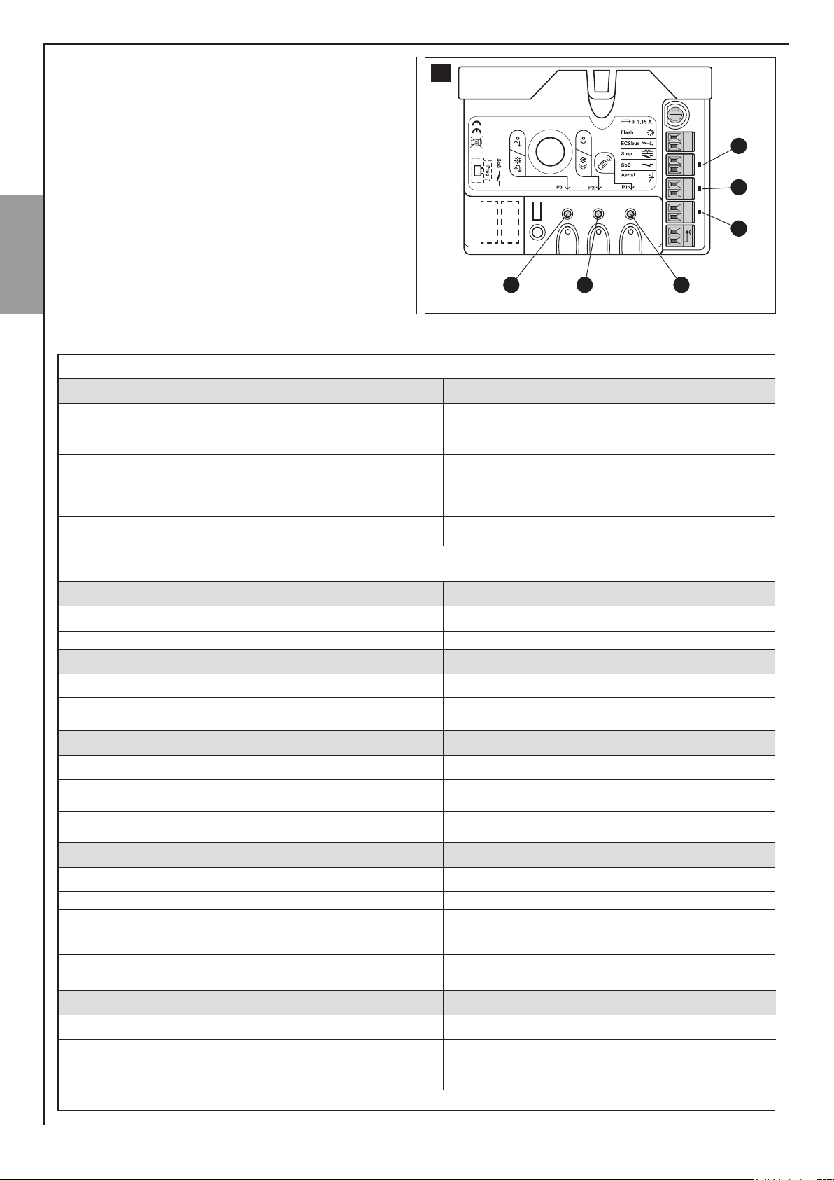
Fig. 3:
The three P1, P2 and P3 buttons [B] and the corresponding LEDs are
used to program the control unit.
The yellow button [C] allows the door to be controlled during testing. The
same key will also be operated during daily use, through the incorporated
orange button [D].
To facilitate the electrical connections there are separate terminals for
each device [A], which are removable and colour-coded based on the
function performed. Next to each input terminal there is a LED that signals
its status.
The connection to the power supply is very easy: just insert the plug in a
power outlet.
h
3
C
B
2.3.2 – PH200 photocells (optional)
The pair of PH200 wall-mounted photocells, once they are connected to
the control unit, enables the detection of obstacles found on the optical
axis between the transmitter (TX) and the receiver (RX).
A
D
English
List of small parts
M6 self-tapping nuts
M6 x14 screws
6,3x38 tcei screws
TABLE 3
GD102
Pcs 2
Pcs 2
Pcs 4
GD103
Pcs 4
Pcs 4
Pcs 4
TABLE 4
List of small parts for PH200
HI LO 4X9,5 screw
3,5X25 self-tapping screw
s 5 c nylon screw anchor
4
Q.ty
Pcs 4
Pcs 4
Pcs 4
English – 3

2.3.4 – FL200 ashing light with incorporated aerial (optional)
2.3.5 – ECCO5... radio transmitter
The ashing light is controlled by the control unit and signals danger hen
the door is moving. Inside the ashing light there is also the aerial for the
radio receiver.
TABLE 6
List of small parts for FL200
4,2X32 self-tapping screw
s 6 c nylon screw anchor
Q.ty
Pcs 4
Pcs 4
6
English
The radio transmitter is used for the remote control of the door opening and closing manoeuvres. It features 5 buttons (T5: not used in this
application) that can all be used for the 4 types of command to a single
automation unit, or to control up to 4 different automation units.
The transmission of the command is conrmed by the LED [A]; an eyelet
[B] allows them to be hung on a keyring.
7
[A] Led
T5
T1
T2
T3
T4
[B]
INSTALLATION
––– STEP 3 –––
The installation must be carried out by qualied and skilled
personnel in compliance with the directions provided in chapter
1 “WARNINGS”.
3.1 – PRELIMINARY CHECKS
AVIO600 and AVIO1000 must not be used to power a door that
is not efcient and safe and cannot solve defects resulting from
incorrect installation or poor maintenance of the door itself.
WARNING: incorrect installation could cause serious damage.
Before proceeding with the installation you must:
• Make sure that the door movement does not hinder roads or
public footpaths.
• After the motor has been installed, remove unnecessary cables
or chains and turn off any unneeded equipment.
• Make sure that the weight and dimensions of the door fall within
the specied operating limits (Chapter 3.1.1). If they do not, AVIO
cannot be used.
4 – English
• Make sure that the structure of the door is suitable for automation and in compliance with regulations in force.
• Make sure that there are no points of greater friction in the opening or closing stroke of the door.
• Make sure that the mechanical structure of the door is sturdy
enough and that there is no risk of it derailing out of the guides.
• Make sure that the door is well balanced: it must not move by
itself when it is placed in any position.
• Make sure that the installation area is compatible with the size of
the gearmotor and that it is safe and easy to release.
• Make sure that the mounting positions of the various devices
are protected from impacts and that the mounting surfaces are
sufciently sturdy.
• Make sure that the mounting surfaces of the photocells are at
and that they enable the proper alignment between TX and RX.
• Pay attention in particular to the methods for securing the head
of the guide and the brackets to the ceiling. The head of the guide
will have to bear all the strain of opening and closing the door; the
ceiling-mounted brackets will have to bear all the weight of AVIO.

In both cases, the wear and deformations which may occur in time
must be taken into consideration.
• Make sure that the minimum and maximum clearances specied
in g. 8 are observed.
8
2970 mm
C
D 420 mm
B 0÷400 mm
• Make sure that, in the position corresponding to the door, or
slightly to the side, (see positions “A” and “B”) the conditions
are suitable for mounting the head of the guide; in particular, the
material should be sufciently sturdy and compact.
Make sure that AVIO can be mounted on the ceiling along position
“C” using the mounting brackets.
If the door to be automated is an overhead type with springs or
counterweights, it will be necessary to install a GA2 OSCILLATING
ARM, which must be mounted next to the handle (Figure 9).
• Make sure that distance [E] in Figure 10, i.e. the minimum distance between the upper side of the guide and the maximum point
reached by the upper edge of the door, is no shorter than 65 mm
and no longer than 100 mm, otherwise AVIO cannot be installed.
A 40÷400 mm
280 mm280 mm
• The gearmotor should be mounted so that it coincides with the
centre of the door, or is slightly off-centre. E.g. in order to mount
the OSCILLATING ARM next to the handle (Figure 9).
9
10
0÷400 mm
B
E 65÷100 mm
If the door closes a room that has no other means of access, we
recommend installation of the GU2 EXTERNAL RELEASE KIT (Figure 11). Otherwise a fault or, for the AVIO600 version with buffer
batteries, a simple power failure could prevent access to the room.
Note: the oscillating arm and external release kit are supplied with
the related assembly instructions.
11
English
EXTERNAL MANUAL RELEASE
B
1) Fit the lever
[A] Lever
[B] Black screw
E
D
2) Fit the steel cable
[C] Sheath
[D] Steel cable
[E] Clamp
A
C
English – 5

3.1.1 – Operating Limits
Chapter 6 “Technical Characteristics” provides the fundamental data
needed to determine whether all the AVIO600 and AVIO1000 components are suitable for the intended application. In general AVIO600 and
AVIO1000 are suitable for the automation of sectional and overhead
TABLE 7
doors for residential applications having the values shown in the table 7.
The shape of the door and the climatic conditions (e.g. presence of strong
wind) may reduce this maximum limit. In this case it is necessary to measure the torque needed to move the door under the worst conditions, and
to compare it to the data provided in the technical characteristics chart.
SECTIONAL doorModel Maximum force
Height
2,4m
3,4m
AVIO600
AVIO1000
600N
1000N
English
3.1.2 – Tools and Materials
Make sure you have all the tools and materials needed to install the system; make sure that they are in good condition and service-
able according to current safety standards. See examples in gure 12.
12
Width
4,4m
5,2m
OVERHEAD door
non-protruding (with GA2)
Height
2,2m
3,2m
Width
4,2m
5m
OVERHEAD door
protruding (with GA2)
or with springs (without GA2)
Height
2,8m
3,5m
Width
4,2m
5m
3.1.3 – List of cables
The cables required for the installation of AVIO may vary depending on the type and quantity of devices to be installed; gure 13 shos the cables
needed for a typical installation; no cable is supplied with AVIO.
13
E
D
B
A
C
C
6 – English
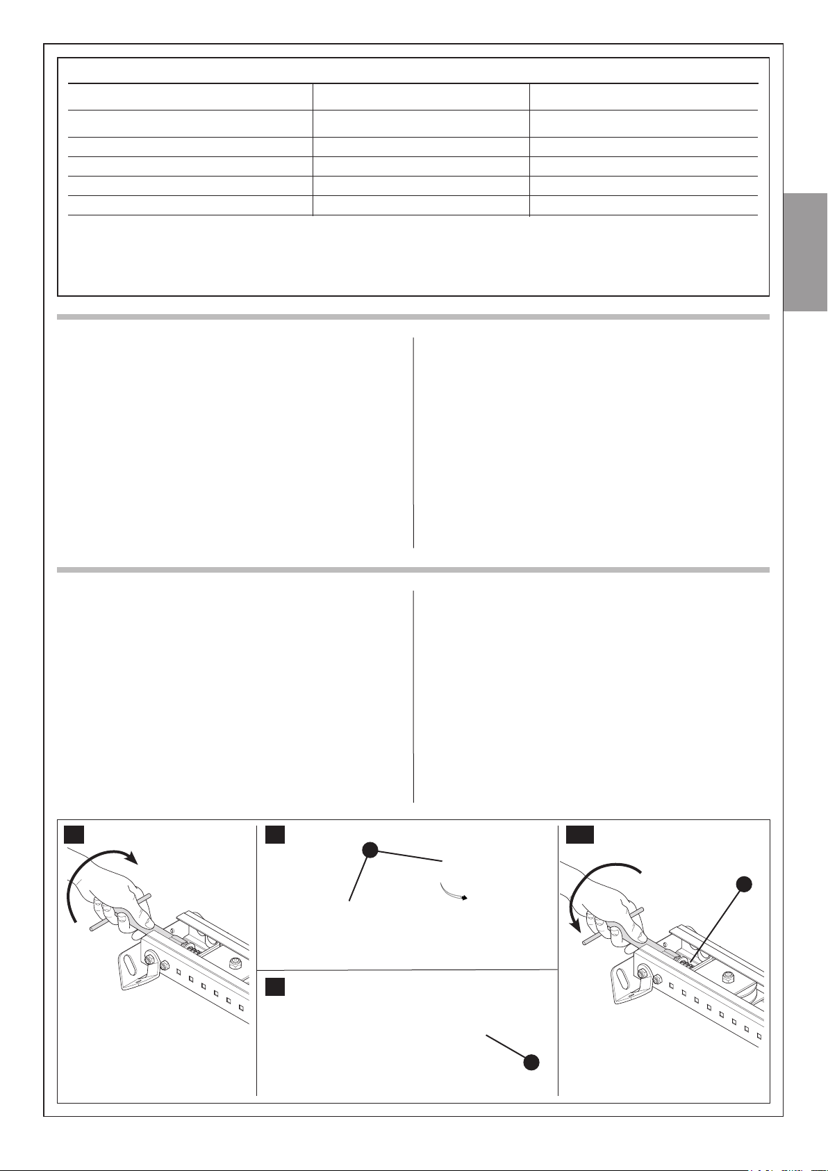
Table 8: List of cables
Connection
[A] STOP input
[B] SbS input
BUS input/output
[C]
[D] FLASH light output
[E] Radio aerial
Note 1 – For the BUS, STOP and SbS cables, there are no special contraindications to the use of a single cable that groups together multiple
connections; for example, a single 4x0,5mm2 cable.
WARNING! – the cables used must be suitable for the type of installation; for example, an H03VV-F type cable is recommended for
indoor applications.
3.2 – PREPARING THE ELECTRICAL SYSTEM
With the exception of the plug and the power cable, the rest of the system
uses extra-low voltage (approx. 24V); the wiring can therefore be done by
personnel that is not properly qualied, provided that all the instructions in
this manual are carefully observed.
After selecting the position of the various devices (refer to gure 13) you
can start preparing the conduits for the electrical cables connecting the
devices to the control unit.
The shock-resistant conduits are designed to protect the electrical cables
and prevent accidental breakage.
Cable type
2 x 0,5 mm
2 x 0,5 mm
TX 2 x 0,5 mm
2 x 0,5 mm
2
cable
2
cable
2
cable
2
cable
RG58 type shielded cable
3.2.1 – Connection to the Electrical Mains
Although the connection of AVIO to the electrical mains is beyond the
scope of this manual, we wish to remind you that:
• The poer supply line must be laid and connected by a qualied
professional electrician.
• Have a suitably protected 16A “schuko” outlet installed, where
you can plug in AVIO.
• Make sure that the power supply cable does not hang over moving parts or hazardous areas.
Maximum length allowed
20 m (note 1)
20 m (note 1)
20 m (note 1)
20 m
20 m (less than 5m recommended)
English
3.3 – INSTALLATION OF THE VARIOUS DEVICES
Depending on the model, the installation of AVIO is comprised of the following parts:
- Assembly of the guide supplied with AVIO600 (see paragraph 3.3.1).
- Assembly of the guide supplied with AVIO1000 (see paragraph 3.3.2).
- Fixing of the gearmotor to the guide (see paragraph 3.3.3).
- Fixing of the gearmotor to the ceiling (see paragraph 3.3.4).
3.3.1 – AVIO600 guide assembly
The guide supplied with AVIO600 must be assembled as follows:
1. Slacken the adjustment screw of the belt tensioner device before
assembling the guide, as in gure 14.
2. Remove the belt from the three pieces that make up the guide
(excluding the part next to the pulley) and place them to one side.
3. With the aid of a hammer, assemble the three pieces of the guide
engaging them into the connection brackets [A] ith force, as in g-
ure 15.
Important – the guides must slide into the brackets until they click into
position.
4. Carefully reposition the belt into the guide, making sure that it is not
twisted.
5. Connect the head [B] ith force into the guide, as in gure 16.
6. Finally, tension the belt with the adjustment screw [C] of the belt ten-
sioner device, as in gure 16a.
Warning - The gearmotor could break if the belt is too TAUT; if it is
too SLACK, it could cause unpleasant noise.
14 15 16a
A
16
C
B
English – 7
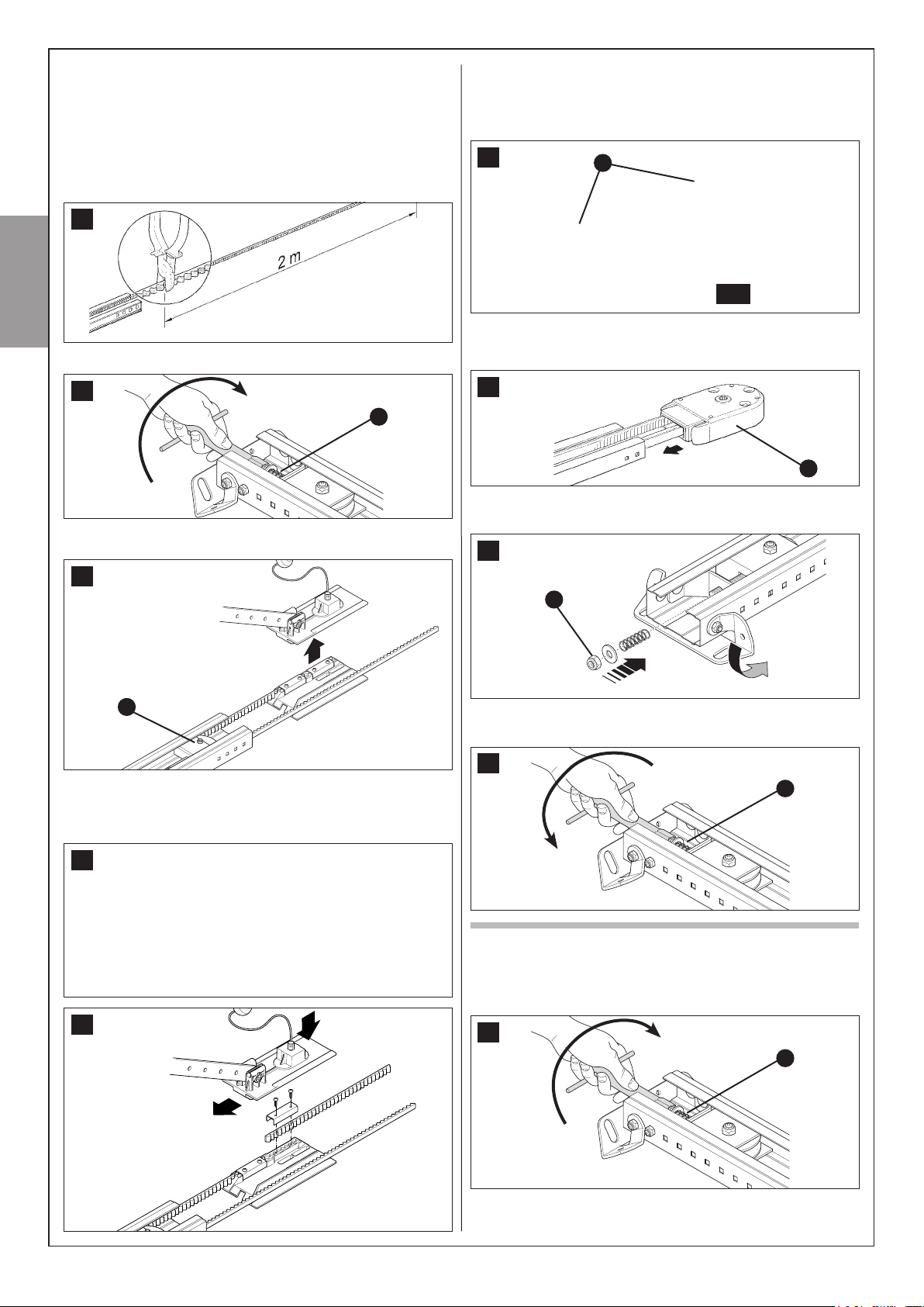
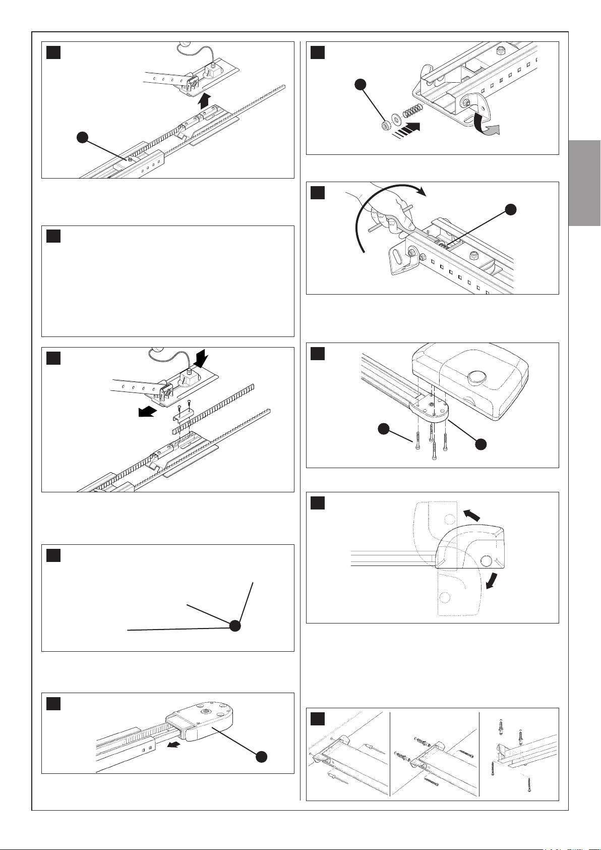
3.3.2 – Assembly of the guide supplied with AVIO1000
The guide is made up of four 1 m long proles, hich permit 2 versions
to be made:
3m VERSION:
If the height of the door to be automated is equal to or less than 2,5 m
assemble the guide as follows:
1 Cut the free end of the belt to obtain a length of exactly 2 metres, as
shon in gure 17.
17
English
2 Loosen the M8 nut [C] completely, as shon in gure 18.
5 With the aid of a hammer, assemble the three pieces of the guide
engaging them into the connection brackets [A] ith force, as in gures
22 and 22a.
Important – the guides must slide into the brackets until they click into
position.
22
A
22a
6 Return the belt tensioner device and carriage to the initial position.
Assemble the guide head section [B], as shon in gure 23. This requires
a certain force; if necessary use a rubber mallet.
18
C
3 Slide the belt tensioner device to mid-stroke [D], as shon in gure 19,
and remove the carriage completely.
19
D
4 Pass the free end of the belt through the head section, as shon in g-
ure 20, and secure IT to the carriage by means of the screws and wash-
ers present, as shon in gure 21. Take care hen positioning the belt: it
must be with the teeth facing inwards, straight and without twists.
23
B
7 Insert the spring, washer and M8 nut [C] in the screw of the belt ten-
sioner device, as shon in gure 24.
24
C
8 Tension the belt by means of the M8 nut [C] (gure 25) until it is sufciently taut.
25
C
20
21
8 – English
4m VERSION:
If the height of the door to be automated is greater than 2,5m assemble
the guide as follows:
1 Loosen the M8 nut [C] completely, as shon in gure 26.
26
C
2 Slide the belt tensioner device to mid-stroke [D], as shon in gure 27,
and remove the carriage completely.
27
D
3 Pass the free end of the belt through the head section, as shown in
gure 28, and secure it to the carriage by means of the scres and ashers present, as shon in gure 29. Take care hen positioning the belt: it
must be with the teeth facing inwards, straight and without twists.
28
32
C
7 Tension the belt by means of the M8 nut [C] (gure 33) until it is suf-
ciently taut.
33
C
3.3.3 – Fixing of the gearmotor to the guide
1 Couple the GD102 gearmotor’s shaft extension with the head of the
guide [B]; then secure them using the four M6,3x45 screws [E].
English
29
4 With the aid of a hammer, assemble the four pieces of the guide into the
three connection brackets [A], as in gures 30.
Important – The guides must slide into the brackets until they click
into position.
30
A
5 Return the belt tensioner device and carriage to the initial position.
Assemble the guide head section [B], as shon in gure 31. This requires
a certain force; if necessary use a rubber mallet.
31
34
E
B
The gearmotor can be rotated in three different positions
35
3.3.4 – Fixing of the gearmotor to the ceiling
1 Observing the A, B and C positions shown in Figure 8, mark the 2 fas-
tening points for the guide’s front bracket in the centre of the garage door
(or slightly off-centre – Figure 11).
Depending on the type of material, the front bracket can be fastened
using rivets, anchors or scres (Figure 36). If positions A, B, and C (gure
8) allow it, the bracket can be fastened directly to the ceiling.
36
B
6 Insert the spring, washer and M8 nut [C] in the screw of the belt ten-
sioner device, as shon in gure 32.
English – 9

2 After drilling the holes, leave the head of the gearmotor on the ground,
lift the guide from the front and secure it with two screws, anchors or rivets depending on the type of surface.
3 Secure the mounting brackets [F] using the screws [G], and nuts [H]
and choosing the hole that is closest to the established position B (see
Figure 8).
37
H
G
Value B
English
F
41
I
8 Slide the carriage until the door mounted bracket [L] shown in Figure
42 is positioned on the upper edge of the door, exactly perpendicular to
the guide [M].
Next, secure the door mounted bracket [L] with screws or rivets. Use
screws or rivets that are suitable for the door material, making sure that
they are capable of bearing all the strain resulting from opening and closing the door.
4 Using a ladder, lift the gearmotor and position the brackets against
the ceiling. Mark the drilling points, then put the gearmotor back on the
ground.
38
5 Drill the holes as marked; then, using a ladder, lift the gearmotor, position the brackets over the holes you have just drilled and fasten them
using screws and anchors suited to the material.
39
42
M
L
9 Loosen the screws in the two mechanical stops, then place the front
mechanical stop [N] before the carriage (Figure 43).
Push the carriage hard in the closing direction and, in the reached posi-
tion, tighten the scre rmly [O].
43
O
N
6 Make sure that the guide is perfectly horizontal, then cut the excess of
the brackets using a hacksaw.
40
7 With the door closed, pull the cord and release the carriage [I] from the
guide.
10 – English
10 Open the door manually to the desired open position, then place the
rear mechanical stop [P] near the carriage (Figure 44) and secure it by
tightening the scre rmly [O].
44
P
O
11 Make sure that the release cord can be activated at a height less than
1,8 m.
3.3.5 –
PH200 photocells (optional)
Caution: disconnect the power supply to the system before performing
any installation operations.
• position each photocell 40/60 cm above the ground • position
them on the opposite sides of the zone to be protected • position
them as close as possible to the door (maximum distance = 15 cm)
• a tube for passing the cables must be present in the fastening
point • orient the TX transmitter towards the central zone of the
RX receiver (allowed misalignment: maximum 5°)
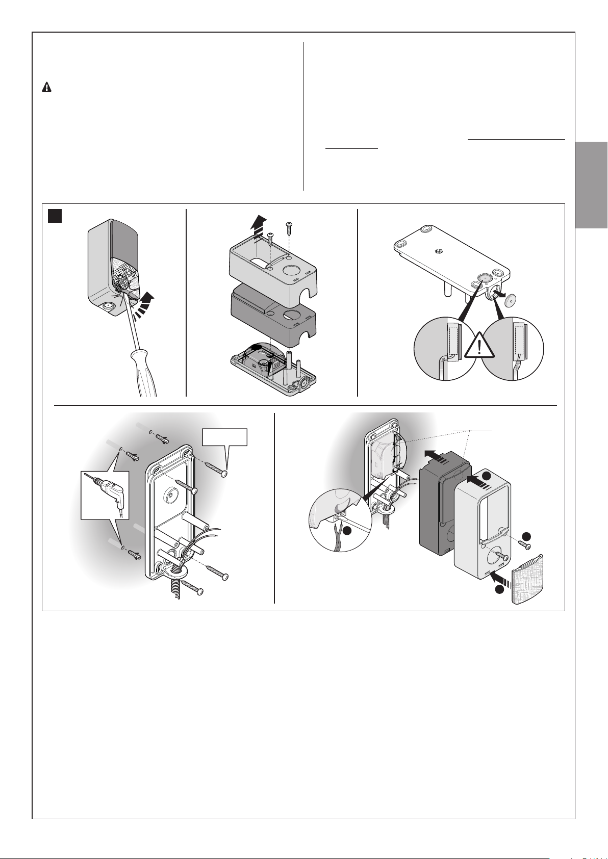
01. Remove the front glass (Phase 01 - Fig. 45)
02. Remove the upper casing then the internal casing of the photocell
(Phase 02 - Fig. 45)
03. Perforate the lower casing in the point where the cables should pass
(Phase 03 - Fig. 45)
04. - Position the lower casing in the point where the tube for the passa-
ge of the cables arrives and mark the perforation points (Phase 04
- Fig. 45)
- Use a percussion drill to drill the wall with a 5 mm bit. Insert the 5
mm wall plugs (Phase 04 - Fig. 45)
- Pass the electrical cables through the relevant holes and fasten the
lower casing with the screws (Phase 04 - Fig. 45)
05. - Connect the electrical cable to the terminals of the TX and RX,
which must be connected in parallel to each other then connected to
the terminal on the control unit (Fig. 65). It is not necessary to observe any polarity.
- Put back in place, in the following order, the inner casing followed
by the upper casing to be fastened with the two screws then, lastly,
insert the cover and exert slight pressure to close it (Phase 05 - Fig.
45).
45
01.
04.
02. 03.
05.
Ø < 5 mm
English
Led SAFE
2
1
3
4
English – 11
3.3.6 – FL200 ashing light (optional)
• The ashing light must be positioned near the door in a clearly
visible position. It can be fasted to a horizontal or vertical surface.
• For connection to the Flash terminal, no polarity needs to be observed;
instead for connection of the shielded aerial cable, it is necessary to connect the cable and sheath as shown in Fig. 46(06) and Fig. 65.
Choose the most suitable position in hich to install the ashing light: it
must be positioned near the door in a clearly visible position. It can be
fasted to a horizontal or vertical surface.
For the installation procedure see Fig. 46.
01. 02. 03. 04.
46
English
1
05. A
05. B
2
Ø = 6 mm
x4
06. 07.
(aerial)(flash)
12 – English
x4
Ø = 6 mm
08. 09.
1
2

3.3.7 – Electrical connections to the control unit
1 Unscrew screw [A] and push button [B], to open the lid.
2 Thread the cables through the slit [C].
3 Refer to gure 65 for the electrical extra lo voltage connection of the
various devices to the control unit terminals.
• The terminals have the same colour coding as the corresponding devices; for example, the grey terminal (SbS) of the control unit must be connected to the grey terminal (SbS) of the accessory.
• For most connections you do not need to observe any polarity; only for
the shielded cable of the aerial incorporated in the FL200 ashing light
(optional accessory) it is necessary to connect the central core and the
shield as shon in gure 65.
• If you are using the asher’s aerial, remove the piece of ire (connected
to the green terminal at the factory) and connect the RG58-type shielded
braiding.
• The terminals [D] can be removed in order to facilitate the operations as
shon in gure 66; make the connections and then reinsert them.
4 When the connections have been completed, secure the cables using
suitable clamps.
5 To close the cover, turn and push until a click is heard. Secure the screw
[A].
64
A
6362
B
C
English
65
FL200
FLASH
PH200
TX RX
NC
NO
66
FLASH
BUSSTOP
SbS
D
English – 13

3.4 – POWER SUPPLY CONNECTION
FLASH
The connection of AVIO to the mains must be made by a qua-
lied electrician.
To carry out tests, insert the plug for AVIO in a power outlet; if necessary,
use an extension cord.
67
English
3.5 – INITIAL CHECKS
As soon as the control unit is energised, you should check the following:
1 Make sure that the LED [A] ashes regularly, ith about one ash per
second.
68
A
71
A
C
B
2 Wait a fe seconds for the control unit to nish recognising the devices.
3 When the recognition procedure is completed, the STOP LED [A] must
remain on, while the P2 LED [B] must go off. If the P2 LED ashes it
means that an error has occurred: see paragraph 5.5 “Troubleshooting”.
The connected devices recognition stage can be repeated again at any
time, even after the installation (for example, if an additional photocell is
installed); just repeat the procedure starting from step 1.
3.5.2 – Recognition of the door’s open and closed positions
After recognising the devices, the control unit must recognise the door’s
open and closed positions. During this stage, the stroke of the door from
the closing stop to the opening stop is detected.
1 Make sure that the carriage is attached.
2 Press key P3 [A] on the control unit and hold it down for at least three
seconds, then release the key (Figure 72).
FLASH
BUSSTOP
2 If the system is equipped with the PH200 photocells, make sure that the
SAFE LED [B] shon in gure 69 ashes (on both TX and RX). The type of
ashing is irrelevant, it depends on other factors; hat matters is that it is
not always off or always on.
SbS
69
Led SAFE
4 If the above conditions are not satised, you should immediately sitch
off the power supply to the control unit and check the cable connections more carefully. For more useful information see also chapters 5.5
“Troubleshooting” and 5.6 “Diagnostics and Signals”.
72
A
B
• Wait until the control unit has completed the recognition stage: closing,
opening and re-closing of the door.
• If any device is triggered during the recognition stage, or the P3 key is
pressed, the recognition stage will be immediately interrupted. In this case
it must be repeated from the beginning.
• During the recognition stage the courtesy light ill ash just like the
ashing light.
3 If the P3 LED [B] ashes at the end of the learning stage, it means that
there is an error; see paragraph 5.5 “Troubleshooting”.
4 Press the yellow button [C] in gure 73 to execute a complete opening
and closing manoeuvre. Then push it again to perform a complete closing
manoeuvre. During these two manoeuvres the control unit memorises the
force needed at each point along the stroke.
73
C
BUSSTOP
SbS
3.5.1 – Recognition of the connected devices
When you have completed the initial checks, the control unit must recognise the devices connected to it on the “BUS” and “STOP” terminals.
1 On the control unit, press the P2 button [C] and hold it down for at least
three seconds, then release the button (Figure 71).
14 – English
It is important that these to rst manoeuvres are not interrupted by any
commands.
If the manoeuvres are not completed, repeat the recognition procedure
starting from step 1.
The position recognition stage can be repeated at any time in the future
(for instance, if one of the mechanical stops is moved); just repeat starting
from step 1.

WARNING: if the belt is not tightened properly, during the
search for the positions it may slip between the belt and the
pinion. If this happens, stop the learning procedure by pressing
key P3 and stretch the belt by tightening the nut [D]. Then repeat
the recognition procedure starting from step 1.
74
D
77
B
3.7 – TESTING AND COMMISSIONING
A
3.5.3 – Testing the radio transmitter
To test the transmitter just press one of its 4 keys, make sure that the red
LED [A] ashes and that the automation carries out the related command.
The command associated to each button depends on how it has been
memorised (see paragraph 5.4 “Memorisation of radio transmitters”).
75
[A] Led
T5
T1
T2
T3
T4
[B]
3.6 – ADJUSTMENTS
3.6.1 – Selecting door speed
The door can be opened and closed at two speeds: “slow” or “fast”.
To switch from one speed to the other press the P2 button [A] momen-
tarily; the corresponding P2 LED [B] will light up or go off; if the LED is off
the speed is “slow”, if the LED is on the speed is “fast”.
76
A
These are the most important operations, designed to guarantee the
maximum safety and reliability of the automation system.
The testing procedure can also be used as a periodic check of the devices that make up the automation.
The testing and commissioning operations must be performed
by qualied and experienced personnel ho must establish hat
tests should be conducted based on the risks involved and verify
the compliance of the system with applicable regulations, legislation and standards, in particular with all the provisions of EN
standards 12445 and 12453 which establish the test methods for
sectional and overhead door automation systems.
3.7.1 – Testing
1 Make sure that the provisions contained in chapter 1 “WAR-
NINGS” have been carefully observed.
2 Using the radio transmitter, test the opening and closing of the door and
make sure that the door moves in the intended direction.
The test should be carried out a number of times to make sure that the
door moves smoothly, that there are no points of excessive friction and
that there are no defects in the assembly or adjustments.
3 Check the proper operation of all the safety devices, one by one (photocells, sensitive edges, etc.). In particular, each time a device is activated,
the BUS LED on the control unit ashes for a longer time, conrming
that the control unit recognises the event.
4 To check the photocells (if provided), pass a 5 cm diameter, 30 cm long
cylinder on the optical axis, rst near TX, then near RX and nally at the
mid-point between them and make sure that in all these cases the device
is triggered, switching from the active to the alarm status and vice-versa;
nally, that it causes the intended action in the control unit, for example:
that it causes the reversal of the movement during the closing manoeuvre.
8
English
B
3.6.2 – Selecting the type of operating cycle
The opening and closing of the door can take place according to different operating cycles:
• single cycle (semiautomatic): the door opens with a command and stays
open until the next command is given, causing it to close.
• complete cycle (automatic closing): the door opens with a command
and then closes automatically after a short time (for the time, see paragraph 5.1.1 “Adjusting the parameters with the radio transmitter”).
To switch from one operating cycle to the other, press the P3 button [A]
momentarily; the corresponding LED P3 [B] will light up or go off; if the
LED is off the cycle is “single”, if the LED is on the cycle is “complete”.
5 The control of the correct obstacle detection is performed with the
700x300x200mm test parallelepiped with 3 black sides and 3 polished
white or mirrored sides, according to the EN 12445 standard.
6 Measure the impact force according to EN standards 12445 and 12453.
If “motor force” control is used to assist the system for the reduction of the
impact force, try to nd the adjustment that gives the best results.
7 Ensure that the entire mechanism is correctly adjusted and that the
automation system inverts the manoeuvre when the door collides with a
50 mm high object on the oor.
8 Ensure that the automation prevents or blocks the opening manoeuvre
hen the door is loaded ith a mass of 20 kg, xed in the middle of the
door’s lower edge.
English – 15

3.7.2 – Commissioning
The commissioning operations can be performed only after all the
tests have been successfully carried out. Partial commissioning
or implementation of “temporary” conditions are not permitted.
1 Prepare the technical documentation for the automation, which must
include at least: assembly draing (e.g. gure 1), iring diagram (e.g. gure 65), analysis of hazards and solutions adopted, manufacturer’s declaration of conformity of all the devices installed. For AVIO use Annex 1 “CE
Declaration of Conformity of the AVIO components”.
2 Post a label on the door providing at least the following data: type of
automation, name and address of manufacturer (person responsible for the
“commissioning”), serial number, year of manufacture and “CE” marking.
3 Fill out the declaration of conformity and deliver it to the owner of the
automation system; for this purpose you can use Annex 2 “CE Declaration of Conformity”.
English
4 Prepare the operating guide and deliver it to the owner of the automa-
tion system; Annex 3 “OPERATING GUIDE” can be used as an example.
5 Prepare the maintenance schedule and deliver it to the owner of the
automation system; it must provide directions regarding the maintenance
of all the automation devices.
6 Post a permanent label or sign detailing the operations for the release
and manual manoeuvre (use the gures in Annex 3 Operating guide).
7 Before commissioning the automation system, inform the owner regarding dangers and hazards that are still existing.
8 Post a permanent label or sign with this image on the door (minimum
height 60 mm) with inscription WARNING – RISK OF CRUSHING.
79
min. 60 mm
MAINTENANCE
––– STEP 4 –––
The maintenance operations must be performed in strict compliance with the safety directions provided in this manual and
according to the applicable legislation and standards.
The devices used for the AVIO automation system do not require any special maintenance. However, periodically make sure (at least once every six
PRODUCT DISPOSAL
This product is an integral part of the automation system it controls and must be disposed of along with it.
As in installation operations, at the end of the product’s lifespan, disposal
operations must be performed by qualied personnel.
The product is made of various types of materials: some of them may be
recycled, while others must be scrapped. Seek information on the recycling and disposal methods envisaged by the local regulations in your
area for this product category.
Warning! – Some parts of the product may contain polluting or hazardous substances which, if released to the environment, may cause serious
damage to the environment or to human health.
As indicated by the symbol alongside, disposal of this product with household waste is prohibited. Separate the waste into categories for disposal,
months) that all the devices are perfectly efcient.
To this end, carry out all the tests and checks described in paragraph
3.7.1 “Testing” and the operations described in paragraph 7.3.3 “Maintenance operations to be performed by the user”.
If other devices are present, follow the directions provided in the corresponding maintenance schedule.
according to the methods established by current legislation in
your area, or return the product to the retailer when purchasing a new version.
Warning! – Local legislation may impose heavy nes in the
event of illegal disposal of this product.
Disposal of buffer battery (if present)
Warning! – Even if discharged, the batteries may contain pollutant sub-
stances and therefore must never be disposed of in normal waste collection points.
Dispose of according to separate waste collection methods as envisaged
by current local standards.
16 – English

ADDITIONAL INFORMATION
––– STEP 5 –––
The following chapters describe different ways of customising AVIO to
make it suitable for specic application requirements.
5.1 – ADVANCED ADJUSTMENTS
5.1.1 – Adjusting the parameters with the radio transmitter
The radio transmitter can be used to adjust certain control unit operation
parameters: there are four parameters and each of them can have four
different values:
1) Pause time: time during which the door remains open (in the automatic
closing mode).
2) Partial opening: partial door opening mode.
3) Motor force: maximum force beyond which the control unit recognises
an obstacle and reverses the movement.
4) “Step-by-Step” function: sequence of movements associated to each
“Step-by-Step” command.
The parameter adjustment operation can be performed using a radio
transmitter, provided it is memorised in mode 1.
If no transmitter memorised in Mode 1 is available, you can memorise one
just for this phase and delete it immediately afterwards (see paragraph
5.4.1 “Memorisation Mode 1” and paragraph 5.4.4 “Deleting a radio
transmitter”).
WARNING:
WARNING: when using the transmitter to make adjustments you need
to give the control unit time to recognise the radio command; this means
that the buttons must be pressed and released slowly, held down for at
least one second, then released for one second and so on.
1 Press buttons T1 and T2 on the radio transmitter simultaneously for at
least 5s.
2 Release the two buttons.
80
T1
T2
3 Within 3 seconds, perform the action described in Table 9 based on the
parameter to be modied
Example: to set the pause time at 40 s.
st
1
Press buttons T1 and T2 and hold them down for at least 5s
2nd Release T1 and T2
3rd Press button T1 three times
All the parameters can be adjusted as required without any contraindication; only the adjustment of the “motor force” requires special care:
• Do not use high force values to compensate for points of abnormal friction on the door. Excessive force can compromise the operation of the
safety system or damage the door.
• If the “motor force” control is used to assist the impact force reduction system, measure the force again after each adjustment in compliance
with EN standard 12445.
• The weather conditions may affect the movement of the door, therefore
periodic re-adjustments may be necessary.
English
Parameters
Pause Time
Partial opening
Motor force
“Step-by-Step”
function
N°
1°
2°
3°
4°
1°
2°
3°
4°
1°
2°
3°
4°
1°
2°
3°
4°
(*) Original factory setting
Setting
10s
20s (*)
40s
80s
Opening the door 1/4 of the way
Opening the door half way (*)
Opening the door 3/4 of the way
Opening the door all the way
Low
Medium-low (*)
Medium-high
High
“Open”-“Stop”-“Close”-“Stop”
“Open”-“Stop”-“Close”-“Open” (*)
“Open”-“Close”-“Open”-“Close”
“Open”-“Open”-“Open” (opening only)
TABLE 9
Action: operation to be performed at point 3 in the adjustment phase
Press button T1 once
Press button T1 twice
Press button T1 three times
Press button T1 four times
Press button T2 once
Press button T2 twice
Press button T2 three times
Press button T2 four times
Press button T3 once
Press button T3 twice
Press button T3 three times
Press button T3 four times
Press button T4 once
Press button T4 twice
Press button T4 three times
Press button T4 four times
5.1.2 – Checking the parameters with the radio transmitter
With a radio transmitter memorised in Mode 1 you can check the
values set for each parameter at any time by following the sequence
described below:
1 Press buttons T1 and T2 on the radio transmitter simultaneously
for at least 5s.
2 Release the two buttons.
3 Within 3 seconds, perform the action described in Table 10 based
on the parameter to be checked.
4 Release the button hen the ashing light starts ashing.
5 Count the ashes and, based on their number, check the corre-
sponding value in Table 10.
Example: If the flashing light flashes three times after you have
pressed T1 and T2 for 5s and then button T1, the pause time is set
at 40s.
English – 17
TABLE 10
Parameter
Pause Time
Partial opening
Motor force
“Step-by-Step” function
Action
Press button T1 and hold it down
Press button T2 and hold it down
Press button T3 and hold it down
Press button T4 and hold it down
5.2 – OPTIONAL ACCESSORIES
In addition to the devices featured in AVIO, other ones are available as
optional accessories designed to enhance the automation system and
improve its safety and performance.
English
PR100: (For AVIO1000 only) 24V buffer battery for power supply in the
event of power failure. It guarantees at last 10 complete cycles.
GA2: OSCILLATING ARM accessory that enables the system to open
overhead-type doors
GU2: MANUAL RELEASE KIT accessory that enables the manual open-
ing of the door even in the event of power failures.
For information on the new accessories, refer to the Nice Home catalogue
or visit the website www.niceforyou.com.
Note 4 Onl to devices it 8,2kΩ constant resistance output can be
connected in parallel; if needed, multiple devices must be connected “in
cascade it a sinle 8,2kΩ termination resistance
Warning: if the STOP input is used to connect devices with safety
functions, only the devices ith 8,2kΩ constant resistance output
guarantee the fail-safe category 3.
During the recognition stage the control unit, like BUS, recognises the
type of device connected to the STOP input; subsequently it commands a
STOP whenever a change occurs in the recognised status.
5.3.3 – Recognition of Other Devices
Normally the recognition of the devices connected to the BUS and the
STOP input takes place during the installation stage. However, if new
devices are added or old ones removed, the recognition process can be
gone through again by proceeding as follows:
1 On the control unit, press the P2 [A] button and hold it down for at least
ve seconds, then release it.
81
A
5.3 – ADDING OR REMOVING DEVICES
Devices can be added to or removed from the AVIO automation system at any time.
Do not add any devices until you have made sure that they
are perfectly compatible with AVIO; for further information
contact Nice Customer Service.
5.3.1 – ECSBus
ECSBus system allows device connections to be made using just 2 ECSBus conductors for both the electricity supply and the communication
signals. All the devices are connected in parallel on the 2 wires of the BUS
itself; each device is individually recognised because a univocal address is
assigned to it during the installation.
The photocells, as well as other devices that adopt this system, can be
connected to BUS, such as safety devices, control buttons, signalling
lights etc.
For information on the ECSBus devices, refer to the Nice Home catalogue
or visit the site www.niceforyou.com.
The control unit recognises all the connected devices individually through
a suitable recognition process, and can detect all the possible abnormalities with absolute precision. For this reason, each time a device connected to BUS is added or removed the control unit must go through the recognition process; see paragraph 5.3.3 “Recognition of Other Devices”).
5.3.2 – STOP input
STOP is the input that causes the immediate interruption of the manoeuvre (with a short reverse run). Devices with output featuring normally open
“NO” contacts and devices with normally closed “NC” contacts, as well
as devices with 8,2kΩ constant resistance output, like sensitive edges,
can be connected to this input. Multiple devices, even of different type,
can be connected to the STOP input if suitable arrangements are made.
To do this, proceed as described in the following table 11:
Note 1. The NO and NC combination can be obtained by placing the
to contacts in parallel, and placin in series to te N contact an 8,2kΩ
resistance (therefore, the combination of 3 devices is also possible: NO,
N and 8,2kΩ
Note 2. Any number of NO devices can be connected to each other in
parallel.
Note 3. Any number of NC devices can be connected to each other in
series.
B
2 Wait a fe seconds for the control unit to nish recognising the devices.
3 When the recognition stage is completed the P2 LED [B] should go off.
If the P2 LED ashes it means that an error has occurred: see paragraph
5.5 “Troubleshooting”.
4 After you have added or removed any devices, the automation system
must be tested again according to the directions contained in paragraph
3.7.1 “Testing”.
5.3.4 – Photocells addition
You can install a pair of photocells (not supplied with AVIO) at any time.
To ensure the correct recognition of the photocells by the control unit, the
former must be assigned addresses by means of jumpers. The routing
operation is performed both on TX as well as RX (arranging the jumpers
in the same manner). Make sure there are no other photocell pairs with
the same address.
The photocells need to be assigned addresses to make sure that they are
correctly recognised among the other BUS devices, and in order to assign
the performed function.
The photocell of a sectional door automation system can be installed folloing that shon in g. 82. Refer to Fig. 83 for overhead door automation systems.
Photo E and Photo F are used in installations that require the complete
protection of the automation system, also in opening.
The recognition phase must be performed after installation or the removal of photocells as described in paragraph “5.3.3 Recognition of Other
Devices”.
5.4 – MEMORISATION OF RADIO TRANSMITTERS
The control unit incorporates a radio receiver for ECCO5 transmitters
(various models). The transmitters supplied are not memorised, therefore
it is rst necessary to memorise the 1st transmitter (Mode 1).
If you wish to memorise a new radio transmitter you have two choices:
TABLE 11
1st device type:
NO NC 8,2kΩ
NO In parallel (note 2) (note 1) In parallel
NC (note 1) In series (note 3) In series
device type:
nd
2
8,2kΩ In parallel In series (note 4)
18 – English

82 83
TABLE 12
Photocell
Internal photocell h= 50 cm;
A
activated when closing
Internal photocell h= 100 cm;
B
activated when closing
External photocell h= 50 cm;
activated when closing and
C
opening
External photocell h= 100 cm;
activated when closing and
D
opening
WARNING: in the AVIO600 version the BUS output has a maximum load of 1 unit (with A type addresses only).
• Mode 1: in this “mode” the radio transmitter is used to its fullest extent,
i.e. all the buttons execute a pre-established command. It is obvious that
in Mode 1 a radio transmitter can be used to command a single automation, i.e.:
Button T1 “Step-by-Step” command
Button T2 “Open partially” command
Button T3 “Open only” command
Button T4 “Close only” command
in the AVIO1000 version it has a maximum load of 6 units; a pair of photocells absorbs power equal to 1 ECSBUS unit.
Jumpers
External photocell activated
E
when opening
Internal photocell activated
F
when opening
INADMISSIBLE
G
CONFIGURATION
5.4.1 – Memorisation mode 1
1 Press button P1 [A] for at least 3s.
84
B
JumpersPhotocell
A
English
• Mode 2: one of the four commands available can be associated to
each button. This mode, used properly, allows you to command 2 or
more different automations; for example:
Button T1 “Open only” command automation N° 1
Button T2 “Close only” command automation N° 1
Button T3 “Step-by-Step” command automation N° 2
Button T4 “Step-by-Step” command automation N° 3
Obviously, each transmitter is a separate unit, and while some are memorised in mode 1 others can be memorised in mode 2 on the control unit.
The overall memory capacity is 150 units; memorisation in mode 1 takes
up one unit for each transmitter while mode 2 takes up one unit for each
button.
Warning: since the memorisation procedures are timed (10s), you
must read the instructions in the following paragraphs before you
proceed with their execution.
When the P1 LED [B] illuminates, release the button.
2 Within 10s, press any button on the radio transmitter to be memorised
and hold it down for at least 3s.
If the memorisation procedure is successful, the P1 LED ill ash 3
times.
3 If there are other transmitters to be memorised, repeat step 2 within the
next 10s, otherwise the memorisation stage will terminate automatically.
5.4.2 – Memorisation mode 2
With the memorisation in mode 2 of the radio transmitter, any one of
the four commands (“Step-by-Step”, “Partial opening”, “Open only” and
“Close only”) can be associated to each button.
In Mode 2 each button requires a separate memorisation stage.
1 Press button P1 [A] (gure 84) on the control unit as many times as the
number corresponding to the desired command, according to the following table:
Once “Step-by-Step” command
Twice “Open partially” command”
3 times “Open only” command
4 times “Close only” command
English – 19

2 Make sure that the P1 LED [B] makes as many quick ashes as the
number corresponding to the selected command.
3 Within 10 s, press the desired button on the radio transmitter to be
memorised, and hold it down for at least 2 s.
If the memorisation procedure is successful, the P1 LED ill ash 3
times slowly.
4 If there are other transmitters to be memorised for the same type of
command, repeat step 3 within the next 10s, otherwise the memorisation
stage will terminate automatically.
5.4.3 – Remote memorisation
A new radio transmitter can be memorised in the control unit without
directly operating the buttons on it. You need to have an “OLD” pre-memorised operational radio transmitter. The “NEW” radio transmitter to be
memorised will inherit the characteristics of the OLD one, i.e. if the OLD
radio transmitter was memorised in Mode 1, the NEW one will also be
memorised in Mode 1. In this case, during the memorisation stage you
English
can press any key on the two transmitters. If, on the other hand, the OLD
transmitter was memorised in Mode 2 you must press the button on the
OLD transmitter which corresponds to the desired command, and the
button on the NEW transmitter to which you wish to associate that command.
Holding the two transmitters, position yourself within the operating range
of the automation and perform the following operations:
1 Press the button on the NEW radio transmitter and hold it down for at
least 5s, then release it.
2 Press the button on the OLD radio transmitter 3 times slowly.
3 Press the button on the NEW radio transmitter once slowly.
At this point the NEW radio transmitter will be recognised by the control
unit and will assume the characteristics of the OLD one.
If there are other transmitters to be memorised, repeat all the steps above
for each new transmitter.
1 Press the P1 button [A] (Figure 85) on the control unit and hold it down.
85
A
B
2 Wait until the P1 LED [B] lights up, then, within three seconds...
3 Press the key on the radio transmitter to be deleted and hold it down
for at least three seconds. If the deletion procedure is successful, the P1
LED ill ash rapidly ve times. If the P1 LED ashes only once sloly, it
means that the deletion procedure has not been successful because the
transmitter is not memorised.
4 If there are other transmitters to be deleted, press the P1 key and repeat
step 3 within ten seconds, otherwise the deletion procedure will be terminated automatically.
5.4.5 – Deleting all the radio transmitters
With this operation all the memorised transmitters are deleted.
1 Press the P1 button [A] on the control unit and hold it down (Figure 85).
2 Wait until the P1 LED [B] lights up, then wait until it goes off, then wait
until it has ashed 3 times.
3 Release the P1 button precisely upon the third ash.
4 Wait approximately 4s for the deletion process to be completed; during
this time the P1 LED ill ash very quickly.
If the procedure is successful, after a fe moments the P1 LED ill ash
slowly 5 times.
5.4.4 – Deleting a radio transmitter
Only if the system features a radio transmitter, you can delete it from the
memory by proceeding as follows.
If the transmitter is memorised in Mode 1, only one deletion procedure
will be needed and at step 3 you can press any button. If the transmitter
is memorised in Mode 2, one deletion procedure will be needed for each
key memorised.
5.5 – TROUBLESHOOTING
The following table contains instructions to help you solve malfunctions
or errors that may occur during the installation stage or in case of failure.
TABLE 13 - g. 86
Symptoms
The radio transmitter does not emit
any signal (the LED [A] does not
light up)
The manoeuvre does not start and
the “BUS” LED [B] does not ash
The manoeuvre does not start and
the courtesy light [G] is off
The manoeuvre does not start and
the courtesy light flashes a few
times
The manoeuvre starts but inverts
immediately
The manoeuvre is carried out but
the ashing light does not ork
The manoeuvre is carried out but
the courtesy light does not work.
Probable cause and possible solution
• Check to see if the batteries are exhausted, if necessary replace them (Paragraph 7.3.4 “Replacing the
remote control battery”).
• Make sure that the power cord is properly plugged into the mains outlet
• Check to see if the fuses [E] or [F] are blown; if necessary, identify the reason for the failure and then
replace the fuses with others having the same current rating and characteristics.
• Make sure that the command is actually received. If the command reaches the SbS input, the corresponding “SbS” LED [D] must light up; if you are using the radio transmitter, the “BUS” LED must make
to long ashes.
• Make sure that the STOP input is active, i.e. that the “STOP” LED [C] comes on. If this does not happen,
check the device connected to the STOP input.
• The photocell test which is performed at the start of each manoeuvre is not successful; check the photocells, also according to Table 12 (Paragraph 5.6.1 Photocells).
• The selected force is too low to move the door. Check for possible obstacles and if necessary select a
higher force as described in chapter 5.1 “Advanced adjustments”.
• Make sure that there is voltage on the ashing light’s FLASH terminal during the manoeuvre (being intermittent, the voltage value is not important: approximately 10-30V ); if there is voltage, the problem is due
to the lamp; in this case replace the lamp with one having the same characteristics.
• Replace the lamp with one having the same characteristics.
20 – English

86
E
B C D
[A] Led
FLASH
BUSSTOP
5.6 – DIAGNOSTICS AND SIGNALS
A few devices issue special signals that allow you to recognise the operating status or possible malfunctions.
5.6.1 – Photocells
The photocells are equipped with a “SAFE” LED (Figure 87) that allows
you to check the operating status at any time.
TABLE 14
LED “SAFE”
Status
SbS
8
G
F
English
Led SAFE
Action
Off
3 quick ashes and a
second’s pause
1 very slo ash
1 slo ash
1 quick ash
1 very quick ash
Always on
5.6.2 – Flashing and courtesy lights
During the manoeuvre the ashing light ashes once every second, hile
the courtesy light is alays on; hen something is rong the ashes
The photocell is not powered or is faulty
Device not recognised by the control unit
The RX receives a perfect signal
The RX receives a fair signal
The RX receives a poor signal
The RX receives a very poor signal
The RX does not receive any signal
TABLE 15
uick ashes
1 ash
1 second pause
1 ash
2 ashes
1 second pause
2 ashes
3 ashes
1 second pause
3 ashes
4 ashes
1 second pause
4 ashes
Status
ECSBus error
Photocell activated
Activation of the “motor force” limiting device
STOP input activation
Make sure that there is voltage (approx. 8-12 V ) on the photocell’s terminals; if the voltage is correct, the photocell is probably
faulty
Repeat the recognition procedure on the control unit.
Make sure that all the photocell pairs on BUS have correct
addresses
Normal operation
Normal operation
Normal operation but you should check the TX-RX alignment and
make sure the glasses are clean
It is at the limit of normal operation, you should check the TX-RX
alignment and make sure the glasses are clean
Check to see if there is an obstacle between TX and RX. Make
sure that the LED on TX ashes once sloly. Check the TX-RX
alignment
are more frequent (half a second); the light ashes tice ith a second’s
pause beteen ashes. The diagnostic ashing itself is signalled by the
courtesy light.
Action
At the starting of the manoeuvre, the devices present do not correspond to those recognised; check and if necessary try repeating
the recognition process. (5.3.3 “Recognition of Other Devices”).
One or more devices may be faulty; check and, if necessary,
replace them.
At the start of the manoeuvre, one or more photocells do not
enable it; check to see if there are any obstacles.
If there is an obstacle impeding the movement no action is
required.
During the movement, the door experienced excessive friction;
identify the cause.
At the start of the manoeuvre or during the movement, the STOP
input was activated; identify the cause.
English – 21
5.6.3 – Control Unit
On the control unit there is a set of LEDs, each of which can give special
indications both during normal operation and in case of malfunctions.
88
FLASH
BUSSTOP
SbS
A
B
C
English
LED OK [A]
Off
On
1 ash per second
2 long ashes
Series of ashes separated
by a pause
LED STOP [B]
Off
On
LED SbS [C]
Off
On
LED P1 [D]
F E D
TABLE 16
Status
Fault
Serious fault
All OK
Input status variation
It corresponds to the ashing and courtesy light’s signal. (See Table 14)
Status
STOP input activation
All OK
Status
All OK
SbS input activation
Status
Action
Make sure there is power supply; check to see if there are blown
fuses; identify the cause of the malfunction and then replace
blown fuses with others having the same characteristics.
This indicates a serious fault; try switching off the control unit for
a few seconds; if the condition persists there is a fault and the
electronic board needs to be replaced
Normal operation of control unit
It is normal when there is a variation to one of the inputs: SbS,
STOP, triggering of photocells or the radio transmitter is used.
Action
Check the devices connected to the STOP input
STOP input active
Action
SbS input not active
This is normal only if the device connected to the SbS input is
actually active
Action
Off
On
Series of quick ashes, from
1 to 4
LED P2 [E]
Off
On
1 ash per second
2 ashes per second
LED P3 [F]
Off
On
1 ash per second
2 ashes per second
22 – English
All OK
Memorisation in Mode 1
Memorisation in Mode 2
Status
All OK
All OK
No device has been memorised or an error
has occurred in the memorised devices
Device recognition stage in progress
Status
All OK
All OK
The positions have not been acquired.
Position recognition procedure in progress
No memorisation in progress
This is normal during memorisation in mode 1 which lasts maxi-
mum 10s
This is normal during memorisation in mode 2 which lasts maxi-
mum 10s
Action
“Slow” speed selected
“Fast” speed selected
There may be faulty devices; check and, if necessary, try repeat-
ing the recognition process (see paragraph 3.5.1 “Recognition of
Connected Devices”).
It indicates that the search for the connected devices is underway
(this stage lasts a few seconds at the most).
Action
Cyclic operation
Complete cyclic operation
Repeat the position recognition procedure again (see paragraph
3.5.2. “Recognition of the door’s open and closed positions”)

TECHNICAL CHARACTERISTICS OF THE VARIOUS COMPONENTS OF THE PRODUCT
The product AVIO600 / AVIO1000 is produced by Nice S.p.a. (TV) I. In order to improve its products, Nice S.p.a. reserves the right to modify their tech-
nical characteristics at any time ithout prior notice. In any case, the manufacturer guarantees their functionality and tness for the intended purposes.
Note: all the technical characteristics refer to a temperature of 20°C.
DESCRIPTION DATA
Type
Adopted technology
Peak thrust [corresponds to the force
necessary to move a leaf]
Nominal torque [corresponds to the
force necessary to keep a leaf moving]
Idling speed
Speed at nominal torque
Maximum frequency of cycles
Maximum continuous cycle time
Operating Limits
Power supply AVIO
Max. absorbed power
Insulation class
Emergency power supply
Flashing light output
Courtesy light
BUS output
“SbS” input
“STOP” input
Radio aerial input
Maximum cable length
Remote control possibility
ECCO5... transmitters memorised
Range of ECCO5... transmitters
Programmable functions
Self-programmed functions
Operating ambient temperature
Assembly
Protection rating
Dimensions / weight
Electromechanical gearmotor for automated sectional and overhead doors incorporating a control
24V
A transformer inside the motor but separated from the control unit reduces mains voltage to the
10,8 Nm 18 Nm
[600 N] [1,000 N]
5,4 Nm 9 Nm
[300 N] [500 N]
0,10 m/s in “slow” speed mode 0,10 m/s in “slow” speed mode
0,18 m/s in “fast” speed mode 0,15 m/s in “fast” speed mode
0,05 m/s in “slow” speed mode 0,05 m/s in “slow” speed mode
0,09 m/s in “fast” speed mode 0,08 m/s in “fast” speed mode
Its structural characteristics make it suitable for use on sectional and overhead doors with coun-
250 W 370 W
--- with PR100 accessory
12V lamp maximum 10W BA15 socket (automotive type lamp), stays on 60s after the manoeuvre
One output with a maximum One output with a maximum
load of 1 ECSBus unit load of 6 ECSbus units
For normally open contacts (the closing of the contact causes the “Step-by-Step” command)
For normally open contacts and/or for 8,2kΩ constant resistance, or normally closed contacts
with recognition of the “normal” status (any variation from the memorised status causes the
Mains power supply: 30 m; inputs/outputs: 20m with aerial cable preferably shorter than 5m
With ECCO5... transmitters, the control unit can receive one or more of the following commands:
From 10 to 50 m ithout aerial, from 50 to 100 m ith aerial incorporated in the FL200 ashing
light. The range can vary if there are obstacles or electromagnetic disturbances, and is affected by
Automatic detection of the type of STOP device (NO or NC contact or 8,2kΩ resistance)
Model GD102 Model GD103
unit complete with radio receiver for “ECCO5...” transmitters.
motor, helical teeth reduction gear; drive guide with timing belt and mechanical release.
nominal voltage of 24V
50 complete cycles per day
(For a maximum of approx. 10 cycles per hour. A maximum of 5 cycles per hour
4 minutes (the control unit limits the continuous operation)
terweights that are within the dimensions and limits indicated in table 7
230 V
I (a safety grounding system is required)
For Led visual signalling devices (mod. FL200)
52 Ω for RG58 or similar type of cable
(observe the directions regarding the minimum gauge and type of cable)
“Step-by-Step”, “Partial opening”, “Open only” and “Close only”
Up to 150 if memorised in mode 1
the position of the receiving aerial incorporated in the ashing light.
“Cycle” or “Complete cycle” operation (automatic closing)
“Slow” or “fast” motor speed
The pause time in the “complete cycle” mode can be set at 10, 20, 40, 80 seconds
The sensitivity of the obstacle detection system can be selected from 4 levels
The operation of the “Step-by-Step” command can be selected from 4 modes
Automatic detection of devices connected to the BUS Output.
Automatic detection of door length and calculation of deceleration points.
380 x 280 x h 110 mm / 4 kg
used by the automation system.
is permitted at 50°C
(±10%) 50/60 Hz
“STOP” command)
-20°C...+50°C
Horizontal
IP40
English
English – 23
USER MANUAL (to be delivered to the end user)
––– STEP 6 –––
This user guide should be stored and handed to all users of the
automation.
6.1 – WARNINGS
l Keep at a safe distance from the moving door until it is com-
pletely open or closed; do not transit through the door until it is
completely open and has come to a standstill. l Do not let children play near the door or with its commands. l Keep the transmitters away from children. l Suspend the use of the automation immediately as soon as you notice something abnormal in
the operation (noises or jolting movements); failure to follow this
warning may cause serious danger and accidents. l Do not touch
moving parts. l Regular maintenance checks must be carried out
by qualified personnel according to the maintenance plan. l Maintenance or repairs must only be carried out by qualified technical
personnel. l Send a command with the safety devices disabled:
If the safety devices do not work properly or are out of order, the door can
still be operated.
01. Command the door with the transmitter. If the safety devices give the
enable signal, the door opens normally; otherwise, reattempt within 3 seconds and keep the control activated. 02. After approximately 2 seconds
the door will start moving in the “man present” mode, that is, so long as
the control is kept activated the door will keep moving; as soon as the
control is released the door will stop.
If the safety devices are out of order, arrange to repair the automation as
soon as possible.
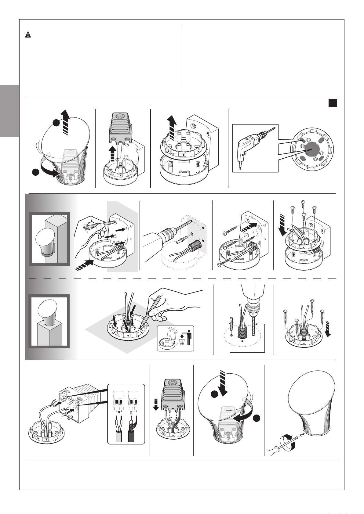
6.2 – Manually
The gearmotor is equipped with a mechanical system that allows for
opening and closing the door manually.
Manual operation must be performed in the case of a power outage or in
the event of anomalies affecting the system.
releasing and locking the gearmotor
6.4 – User-admissible maintenance operations
The operations that the user must carry out periodically are listed below:
• Cleaning of the surfaces of the devices: use a slightly damp (not
wet) cloth. Do not use substances containing alcohol, benzene,
thinners or other flammable substances; the use of these substances may damage the devices and cause fires or electric
shocks.
• Removal of leaves and stones: disconnect the power supply before proceeding, so as to prevent anyone from moving the door.
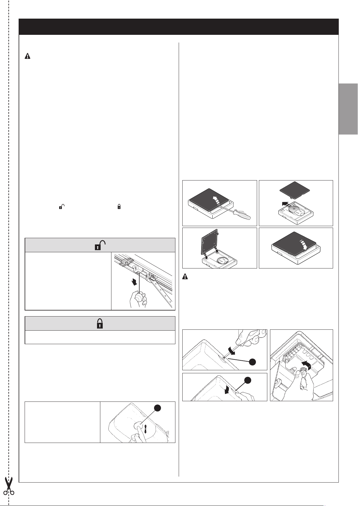
6.5 – Replacing the transmitter battery
When the battery is flat, the transmitter capacity is significantly reduced.
If, when a button is pressed, the relevant Led turns on then immediately
fades and turns off, it means that the battery is completely flat and should
be immediately replaced.
If instead the Led turns on only for a moment, it means that the battery is
partially flat; the button must be kept pressed for at least half a second for
the transmitter to attempt to send the command.
However, if the battery level is too low to complete the command (and
possibly wait for the response), the transmitter will turn off and the relevant Led will fade. In these cases, normal transmitter operation can be
restored by replacing the battery with another of the same type, while
observing the relevant polarity. To replace the battery, proceed as shown
below.
a b
c d
English
1 Pull the release cord down until you
hear the carriage being released.
2 The door can now be moved
manually.
The activation of the manual release may cause an uncontrollable
movement of the door if the springs
are weak or broken, or if the door is
off-balance.
To restore the functionality of the automation system, move the door
back in position until you hear the carriage being engaged.
In the event of a gearmotor fault, it is still possible to try release the motor
to check whether the fault lies in the release mechanism.
6.3 – Door Control
• With radio transmitter
The command associated to each button depends on how it has been
memorised.
• With button (integrated)
You can control the door movement by acting directly on the
orange button [A]
A
Batteries contain polluting substances: do not dispose of them
together with common waste but use the methods set forth in the
local regulations.
6.6 – Lamp replacement
Before proceeding, disconnect AVIO500 from the power supply.
1 Unscrew screw [A] and push button [B], to open the lid.
2 Push the lamp up and rotate to remove. Insert a new 12V / 10W lamp
with BA15 socket.
A
B
English – 25

ANNEX 1
EC DECLARATION OF CONFORMITY
In conformity to Directive 2006/42/EC, ANNEX I, Part A (EC declaration of conformity for machinery)
––––––––––––––––––––
The undersigned / company (name or company name of the subject who/that commissioned the motor-driven door):
. . . . . . . . . . . . . . . . . . . . . . . . . . . . . . . . . . . . . . . . . . . . . . . . . . . . . . . . . . . . . . . . . . . . . . . . . . . . . . . . . . . . . . .
Address: . . . . . . . . . . . . . . . . . . . . . . . . . . . . . . . . . . . . . . . . . . . . . . . . . . . . . . . . . . . . . . . . . . . . . . . . . . . . . . . .
. . . . . . . . . . . . . . . . . . . . . . . . . . . . . . . . . . . . . . . . . . . . . . . . . . . . . . . . . . . . . . . . . . . . . . . . . . . . . . . . . . . . . . . .
English
Hereby declares under its/his/her sole responsibility that:
- The automation: o motorized sectional door o motorized overhead door
- Serial N°: . . . . . . . . . . . . . . . . . . .
- Year of manufacture: . . . . . . . . . . . . . . . . . . .
- Location (address): . . . . . . . . . . . . . . . . . . . . . . . . . . . . . . . . . . . . . . . . . . . . . . . . . . . . . . . . . . . . . . . . . . . . . . .
. . . . . . . . . . . . . . . . . . . . . . . . . . . . . . . . . . . . . . . . . . . . . . . . . . . . . . . . . . . . . . . . . . . . . . . . . . . . . . . . . . . . . . . .
Complies with the essential requirements of the following directives:
2006/42/EC “Machines” Directive
and as provided for in the following harmonised standards:
EN 12445 “Industrial, commercial and garage doors and gates. Safety in use of Power-operated doors and
gates – Test Methods”
EN 12453 “Industrial, commercial and garage doors and gates. Safety in use of Power-operated doors and
gates – Requirements”
Name: . . . . . . . . . . . . . . . . . . . . . . . . . . . . . . . . . . . . . Signature: . . . . . . . . . . . . . . . . . . . . . . . . . . . . . . . . . . . . . . .
Date: . . . . . . . . . . . . . . . . . . . . . .
Place: . . . . . . . . . . . . . . . . . . . . . . . . . . . . . . . . . . . .
English – 27

CE declaration of conformity and declaration of incorporation for a
“quasi-machine”
Declaration in accordance with Directives: 1999/5/EC (R&TTE), 2014/30/EC (EMC); 2006/42/EC (MD) annex II, part B
Note - The content of this declaration corresponds to the declaration made in the official document filed in the offices of Nice
S.p.a., and particularly the latest version thereof available prior to the printing of this manual. The text herein has been re-edited
for editorial purposes. A copy of the original declaration can be requested from Nice S.p.a. (TV) IT.
Number: 582/AVIO Revision: 0 Language: EN
English
Name of manufacturer: Nice s.p.a.
Address: Via Pezza Alta 13, 31046 Rustignè, Oderzo (TV) Italy
Person authorised to provide technical documentation: Nice s.p.a.
Product type: Gearmotor 24Vdc assembled, with incorporated control unit and receiver
Model / Type: AVIO500C, AVIO600C, AVIO1000C, AVIO500CC
Accessories: GA2, GU2, PR100, KS200KIT, ECCO5BO, ECCO5WO
The undersigned Roberto Griffa, as Chief Executive Officer, hereby declares under his own responsibility that the products specified above comply with the provisions of the following directives:
• DIRECTIVE 1999/5/EC OF THE EUROPEAN PARLIAMENT AND COUNCIL of 9 March 1999 regarding radio equipment and
communications terminals and the mutual recognition of their conformity in accordance with the following harmonised standards:
- Health and safety: EN 62479:2010
- Electrical safety: EN 60950-1:2006 + A11:2009 + A12:2011 + A1:2010 + A2:2013
- Electromagnetic compatibility: EN 301 489-1 V1.9.2:2011; EN 301 489-3 V1.6.1:2013
- Radio spectrum: EN 300 220-2 V2.4.1:2012
• DIRECTIVE 2014/35/EU OF THE EUROPEAN PARLIAMENT AND OF THE COUNCIL of 26 February 2014 on the harmonisation of the laws of the Member States relating to the making available on the market of electrical equipment designed for
use within certain voltage limits (recast), according to the following standards: EN 60335-1:2002 + A1:2004 + A11:2004 +
A12:2006 + A2:2006 + A13:2008 + A14:2010 + A15:2011; EN 60335-2-95:2015 + A1:2015, EN 62233:2008
ANNEX 2
The product also complies with the following directive in accordance with the requirements for “quasi-machines”:
Directive 2006/42/EC OF THE EUROPEAN PARLIAMENT AND COUNCIL of 17 May 2006 regarding machines and amending
directive 95/16/EC (consolidated text)
• I declare that the pertinent technical documentation has been prepared in accordance with Annex VII B to Directive 2006/42/
EC and that the following essential requirements have been met: 1.1.1 - 1.1.2 - 1.1.3 - 1.2.1 - 1.2.6 - 1.5.1 - 1.5.2 - 1.5.5 -
1.5.6 - 1.5.7 - 1.5.8 - 1.5.10 - 1.5.11
• The manufacturer agrees to send the national authorities pertinent information on the “quasi-machine” in response to a motivated request without affecting its intellectual property rights.
• If the “quasi-machine” is operated in a European country with an official language other than the language used in this declaration, the importer must associate a translation with this declaration.
• The “quasi-machine” must not be operated until the final machine in which it is to be incorporated is declared to conform to
the provisions of Directive 2006/42/EC, if applicable to it.
The parts of the product which are subject to the following standards comply with them:
EN 13241-1:2003 + A1:2011; EN 12445:2000; EN 12453:2000; EN 12978:2003 + A1:2009
Oderzo, 28 July 2016
Eng. Roberto Griffa
(Chief Executive Officer)
28 – English

Service Après Vente France
En cas de panne, merci de contacter obligatoirement
notre Service Après Vente par téléphone ou par email :
0 820 859 203
Service 0,15 €/min + prix appel
niceservice@niceforyou.com
Merci de ne pas retourner le produit en magasin
Worldwide Customer Service
customerservice@niceforyou.com
Nice S.p.A.
Via Pezza Alta, 13
31046 Oderzo TV Italy
infoniceforyou.com
IS0498A01MM_19-01-2017
www.niceforyou.com
 Loading...