


Vehicular Swing Gate Operator
Nice
Gate
Operators
Titan 912L
The Titan 912L Gate Operator is intended for use with vehicular swing
gates.
The Titan 912L Gate Operator can be used in Class I, Class II and
Class III applications.

TABLE OF CONTENTS

LIST OF FIGURES
Figure 5-1 Left And Right Hand Swing Pivot Point
Figure 5-2
Figure 5-3
Figure 5-4 Hinge Post
Figure 5-5 Actuator Mounting
Figure 5-6
Figure 5- 7
Figure 5-8 Manual Release Handle
Figure 5-9
Figure 5-10 Titan Actuator Wiring
Figure 5-11 Titan Actuator Wiring (Standard)
Figure 5-12 Titan Actuator Wiring (Push To Open)
Figure 5-13 Actuator Motor Leads
Figure 5-14
Figure 5-15 Limit And Motor Connection To The Board
Figure 5-16 Gate Bracket Mounting
Figure 5-17
Figure 5-19
Figure 5-20 Learning Mode - Closed Limit
Figure 6-1 Board Outputs
Figure 6-2
Figure 6-3 Communication Buses
Figure 7-1 Equipment Safety Warnings
Figure 9-1 Fire Department Input
Figure 9-2 Magnetic Lock Wiring (Example)
Figure 9-3 Guard Station Inputs
Figure 9-4 Exit And Edge Inputs
Figure 10-1 Radio Receiver
Figure 12-1 Layout For Inground Loops
Figure 12-2 Layout For Photocells
Figure 14 -1
Figure 13-3 Manual Release Disable
Vertical Pivot Position
Pivot Arm Installation
Control Box Mounting
Incoming Power Wiring 7
Titan Actuator Wiring 8
Actuator Motor Leads 9
Limit Switch Adjustment
Learning Mode - Open Limit
Board Inputs
Manual Release 19
5
5
6
6
6
7
8
8
8
8
9
9
10
10
10
10
12
12
13
14
15
15
15
15
16
17
17
19

1
DO NOT CONNECT
A
/C POWER TO THIS
C
IRCUIT BOARD!
This circuit board is designed for
10VDC - 35VDC power input only.
• Vehicular Swing-Gate Operator (or system) - A vehicular
gate operator (or
system) that controls a gate which swings
or rotates in a direction that is intended for use for vehicular
entrance or exit to a drive, parking lot, or the like.
• Gate - A moving barrier such as a Swinging, sliding, raising,
lowering, rolling, or like barrier that is a stand-alone passage
barrier or is that portion of a wall or fence system that
controls entrance and/or egress by persons or vehicles and
completes the perimeter of a defined area.
• Residential Vehicular Gate Operator - Class I - A vehicular
gate operator (or system) intended for use in a home of one
to four single family dwellings,
or a garage or parking area
associated therewith.
• Commercial / General Access Vehicular Gate Operator -
Class II - A vehicular gate operator (or system) intended for
use in a commercial location or building such as a multi-
family housing unit (five or more single
family units), hotel,
garages, retail store, or other buildings servicing the general
public.
• Commercial / General Access Vehicular Gate Operator -
Class III - A vehicular gate operator (or system) intended for
use in an industrial
location, loading dock area, or other
location not intended to service the general public.
912L
The Titan 912L swing gate operator delivers the next generation of
easily installed, configured and maintained swing gate operators
from Nice. With a maximum gate capacity of 600 lbs and 20 ft,
this operator has a key lockable manual release, easily accessible
limit switch settings as well as simple in-the-field maintenance and
repair. The Titan gives dealers, installers and homeowners the
ability to take control of their access and security systems.
Combining the Titan with Nice brand control boards like the 1050
will bring solid performance for hundreds of thousands of open
and close cycles. This operator includes a 2-year factory warranty
against manufacturing defects and lifetime customer support.
ll
ll
l
This manual provides documentation for mechanical installation and electrical wiring of the Titan swing gate opener with the Nice-brand 1050 gate
operator. The Titan swing gate opener is intended for residential gate installations only. Please consult your Nice distributor or Nice dealer/installer for
more information regarding installations or questions not specifically covered
in this manual.
l
ll
ll
ll
ll
Optionally Available

2.2 - Gate latches
death.
death.
2.4 - Swing and Slide Gates
and slide g control
point to or
or s lide
autono
periodic schedule.
2.5 - General requirements
countles s
AUTOMATIC GATES ARE
NOT FOR PEDESTRIANS!
3 - SAFETY AND CAUTIONS
WARNING
IMPORT
ANT SAFETY INSTRUCTIONS
WARNING - TO REDUCE THE RISK OF INJURY OR DEATH READ AND
FOLLOW ALL INSTRUCTIONS.
3.1 - Properly installed safety devices
3.2 - Safety signs, notices to personnel warning signs
danger posed
t lashing lamp that i s
acti te tim
2

d
3.3 - Gate system safety devices
3.4 - Infrared beams and warning signs
3.5 - Establish the location
3.6 - Read and follow all instructions
3.7 - Keep childr
en away
main
them regu
application.
4.1 - Follow Instructions
4.2 - Intended usage
4.3 - Warnings, cautions and notes
3.8 - Test the gate system
release.
3.9 - Keep gates pr
technicians are not recommended.
operly maintained
i
4 - PRE-INSTALLATION NOTES
operator.
can
can
incorporated in all installations.
the application.
tions.
and s houl
gate operation.
3
reach through gate

4
4.3.16 Protrusions shall not be permitted on any gate, refer to ATSM
F2200 for exceptions, if any.
4.3.17 Gates shall not be designed, constructed and installed in such a
manner that gravity will cause or initiate movement in any direction
whether the operator is attached or not.
4.3.18 A pedestrian gate shall not, under any circumstances, be attached
to, or incorporated into, and vehicular gate system in manner. This
also applies to any fence or wall, or any portion thereof, that the
gate may cover in the open or closed position.
4.3.19 Any non-automated gate that is to be automated in any manner
should be upgraded to conform to the provisions contained within
the provisions of this document and ASTM F2200 as applicable.
4.3.20 To reduce the risk of severe injury or death please read and under stand this entire manual and your local code requirements prior to
starting installation. Additionally, understanding the ASTM standards
will assist you in the proper assembly, installation and operation of
your gate opening system.
4.3.21 Disconnect all electricity and/or all sources of power before per forming any maintenance.
4.3.22 To reduce the risks of fire or injury always contact the installer or
distributor prior to performing any repairs or maintenance.
4.3.23 Never operate gate with obstructions present.
4.3.24 No one should ever cross the operative path of the gate.
4.3.25 Never let children play or linger in the vicinity of the gate or opener
equipment.
4.3.26 Never operate the gate or the opener when the opener is not oper ating or adjusted correctly.
4.3.27 Never allow children to play with or manipulate gate controls. Keep
all remotes away from children.
4.3.28 Only use the MANUAL RELEASE when gate is completely station ary. Untrained persons should never touch the gate or any releases
if any are installed or applicable.
4.3.29 Test the gate operator periodically (once every 6 months minimum).
Gate must reverse course or stop immediately upon contact with
any source in its path. Gate must stop and reverse course at any
time any object or other item crosses the path of the gate. Should
the safety sensors not stop and/or reverse the gates travel, imme diately investigate and repair the inoperative condition. Gate should
not be used under any circumstances, if all sensors and safety de vices are not performing to standards illustrated within this manual.
4.3.30 Gate should not be used if safety devices are not performing to all
local, state and federal guidelines.
4.3.31 Replace fuse only with fuse of same type and rating.
4.3.32 Installation of this gate system in a manner inconsistent with the
manufacturer’s recommended instructions, local, State, or Federal
law transfers the liability unto the installer. Careful consideration has
been taken by the manufacturer’s to devise safe measures, safe
design sad incorporate safety measures to prevent injury, death
or property damage. By circumventing, ignoring or modifying any
safety system or the exclusion thereof, the installer is creating a new
untested process outside the purview of the manufacturer and
therefore assumes all risk.
4.3.33 This unit is not to be installed on any gate, door or other structure
which serves to block, secure, close off or otherwise control a
pedestrian entry point or access point.
4.3.34 Vehicular swing gates shall be designed, constructed and installed
in accordance with security related parameters specific to the appli cation in question, with absolute safety in all considerations.
4.3.35 Never mount any device that operates the gate opener where the
user can reach around, over or through the fate to operate the con trols. Controls should be mounted at minimum, 8 feet away from
any moving part of the gate or gate system.
4.3.36 A hard wired control shall be located in such a manner so that
electronic communication between the two is never interrupted or
the wires damaged.
4.3.37 Any controls used to reset the device after obstruction/entrapment
protection incidents should be located within view of the gate and
should have safety features that prevent unauthorized use.
4.3.38 Never allow anyone to ride, hang on or otherwise touch the gate.
4.3.39 Safety sensors must be present at all times. The hard wired safety
sensors must be arranged and installed in such a manner so that
the communication between gate operator and sensor(s) are never
interrupted or severed by mechanical damage or movement. All items
which have sensors or safety devices installed must be constructed
or installed in such a manner so as to prevent removal or damamge.
All subsequent sensors must be suitable for the system installed and
approved for use.
4.3.40 Never increase the force used to move the gate, beyond the absolute
minimum required.
4.3.41 Never use force adjustments to compensate for binding, sticking or
resistant operation. These situations should be addressed and cor rected before installation of the gate operator. Gate systems should
swing freely in all directions prior to installation of this gate operator.
4.3.42 After any adjustment is made, all safety modes/features must be
tested. Gate must stop or reverse upon any object crossing the path
of the gate or the fate comes into contact with any object.
4.3.43 Activate gate only when the gate is in clear view of the user, the gate
system is properly adjusted, tested and verified, and there are no
obstructions present.
4.3.45 Keep gate and gate system properly maintained and properly in spected at all times.
4.3.46 This operator is intended for installation only on swing and slide
gates used to control vehicular traffic.
4.3.47 The gate must be properly installed and work freely in both directions
prior to the installation of the gate operator.
4.3.48 Install the gate operator only when the operator is appropriate for the
construction and the usage class of the gate.
4.3.49 The gate must be properly installed and work freely in both directions
prior to the installation of the gate operator.
4.3.50 Controls must be far enough from the fate so that the user is
prevented from coming in contact with the gate while operating the
controls. Controls intended to be used to reset an operator after two
sequential activations of the entrapment protection device(s) must
be located in the line of sight of the outdoor gate or easily accessible
controls shall have a security feature to prevent unauthorized use.
4.3.51 All warning signs and placards must be installed where visible in the
area of the gate.
4.3.52 Care shall be given to reduce the risk of nuisance tripping such as
when a vehicle trips the sensor while the gate is still moving.
4.3.53 Gate operators must utilize a contact sensor such as an edge sensor.
4.3.54 A hardwired contact sensor shall be located and its wiring arranged
so that the communication between the sensor and the gate opera tor is not subject to mechanical damage.
4.3.55 A wireless contact sensor such as one that transmits radio frequency
(RF) signals to the gate operator for entrapment protection functions
are recommended.

5
5 - INSTALLATION PROCEDURES
OVERHEAD VIEW
FIGURE 5 - 1 PULL TO OPEN INSTALLATION - LEFT AND RIGHT HAND SWING PIVOT POINT
FIGURE 5 - 2 VERTICAL PIVOT POSITION
V
ERTICAL POSITION OF PIVOT ARM
SIDE VIEW
The top edge of the Pivot Arm will be located 1/2”
below the center line for the gate bracket. The Pivot
Arm must be level when secured.
NOTE
If
you have columns built around
your gate hinge post, check these
measurements for proper clearance
before proceeding with this pull to
open installation.
5.1 - Pivot Arm Installation
IMPORT
ANT
-
Never weld parts to the gate or posts when the operator circuit board is powered. Doing so may
damage the board beyond repair.
PULL TO OPEN INSTALLATION - PIVOT ARM INSTALLATION - Location of Pivot Point
The following instructions provide up to 105° of swing.
Measurements are taken from the center of pivot of the gate hinge.
The pivot arm needs to be securely mounted to the hinge post or equivalent mounting surface. It is recommended to weld
the pivot arm to a metal post. In order to achieve the correct articulation, geometry and rate of speed of the gate it is
critical that the measurements below are followed. The pivot arm may need to be cut to achieve the correct placement of
the actuator mounting hole. Measurements are taken from the center of pivot of the gate hinge.
Center line of
attachment point
for gate bracket
Hinge Post
I
I I
I
I
I

5.2 - Push to open installation
PIVOT ARM INST
ALLATION - Location of Pivot Point
Measurements are taken from the center of pivot of the gate hinge.
The pivot arm needs to be securely mounted to the hinge post or equivalent mounting surface. It is recommended
to weld the pivot arm to a metal post. In order to achieve the correct articulation, geometry and rate of speed of the
gate it is critical that the measurements below are followed. The pivot arm may need to be cut to achieve the correct
placement of the actuator mounting hole. Measurements are taken from the center of pivot of the gate hinge.
LEFT HAND SWING RIGHT HAND SWING
HINGE POST HINGE POST
6”
11”
FIGURE 5 - 3 PIVOT ARM INSTALLATION
DIRECTION OF OPENING
TES CLOSED
GA
TOP VIEW
6”
11”
Center line of attachment point
Vertical Position Of Pivot Arm
for gate bracket
The top edge of the Pivot Arm will be located 1/2”
below the center line for the gate bracket. The
Pivot Arm must be level when secure
d.
5.3 - Actuator mounting
Mount the actuator to the pivot arm as shown.
Please notice the washer goes below the actuator
The lock nut should be tight to prevent movement or
shifting when the actuator is running. This will also
event excessive “bounce” or “wobble” when the gate
pr
stops moving.
FIGURE 5 - 5 ACTUATOR MOUNTIN
Hinge Post
FIGURE 5 - 4 HINGE POST
G
6

5.4 - Control box mounting
Mount the control box within 4 feet of the pivot arm. Use mounting hardware
capable of supporting the weight of the contro
l box with the battery installed.
Do not mount the control box where the person using the push button on
side of the box can come in contact with the gate.
Set battery inside of control box with terminals toward the front (Do not use
any battery with side terminals).
FIGURE 5 - 6 CONTROL BOX MOUNTING
5.5 - Incoming power wiring
Power input connections should be wired as follows:
Solar Panel
Connect wires to the solar panel terminal block. The positive wire
Note: If the panel is connected backwards a red LED will illuminate below the terminal.
of the panel connects to the left terminal marked “+”.
If solar power is to be used it will be
necessary to program control board for STANDBY operation.
Battery
Connect wires to the battery terminal block. The positive wire of the battery connects to the left terminal marked “+”.
NOTE
the battery is connected back-
If
wards a red LED will illuminate below
the terminal.
Main Power - This terminal block is for incoming 10-35VDC power only!
Connect wir
es to the main power terminal block. Positive of the power supply connects to the left terminal marked “+”. This
input should only be used with a power supply capable of supplying 10-35VDC at 20 amps.
NOTE
If supply is connected backwar
ds, a
red LED will illuminate below the
terminal. If supply is connected
properly, a green LED will illuminate.
TTERY
+ -
BA
MAIN POWER
SOLAR PANEL
FIGURE 5 - 7 INCOMING POWER WIRING
7

8
5.6 - Titan actuator wiring
Actuator Limit Switch And Smart Sensor Wiring Actuator Limit Switch And Smart Sensor Wiring
Connect the actuator cable to the 5-pin connector as shown
below. These connections enable the limit switch and smar
t
sensor inputs into the gate controller.
Connect the actuator cable to the 5-pin connector as shown
below. These connections enable the limit switch and smart
sensor inputs into the gate controller.
TITAN ACTUATOR WIRING (STANDARD)
TITAN ACTUATOR WIRING (PUSH TO OPEN)
Terminal Block
For Harness
Connections
Connect the wiring to the actuator terminal block as shown.
Limits and
Encoder
White: Close limit
Orange: Open Limi
t
Green: Limit Common
Yellow: Encoder Signal
Blue: Encoder Power
Green
Ye
llow
Blue
Orange
White
Limits and
Encoder
White: Close limit
Orange: Open Limit
Gr
een: Limit Common
Yellow: Encoder Signal
Blue: Encoder Power
Green
Ye
llow
Blue
White
Orange
With the release handle up, remove the screws from the limit cover and remove the cover. On the bottom of the actuator
loosen the strain relief nut and insert the wire into the actuator housing. The connections are on the top of the atuator behind
the limit assembly.
Using the supplied key, unlock the manual release handle. Lift upwards on the release handle as shown.
EXTEND LIMIT
COMMON
ENCODER
ENCODER
MOTOR -
MOTOR +
RETRACT LIMIT
NOTE
WHITE
ORANGE
YELLOW
BLUE
BLACK
RED
GREEN
FIGURE 5 - 8 MANUAL RELEASE HANDLE
FIGURE 5 - 9 TITAN ACTUATOR WIRING
FIGURE 5 - 10 TITAN ACTUATOR WIRING
FIGURE 5 - 11 TITAN ACTUATOR WIRING (STANDARD)
FIGURE 5 - 12 TITAN ACTUATOR WIRING (PUSH TO OPEN)
1
2
2
3
3
1
4
4
5
5
l
ll
I
l ll
l
l
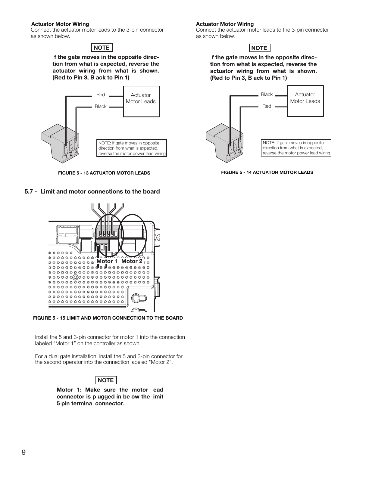
Actuator Motor Wiring
Actuator
Motor Leads
NOTE: If gate moves in opposite
direction from what is expected,
reverse the motor power lead wiring
Red
Black
Actuator Motor Wiring
Connect the actuator motor leads to the 3-pin connector
as shown below.
Connect the actuator motor leads to the 3-pin connector
as shown below.
Actuator
Motor Leads
NOTE: If gate moves in opposite
direction from what is expected,
reverse the motor power lead wiring
Black
Red
Motor 1 Motor 2
Install the 5 and 3-pin connector for motor 1 into the connection
labeled
"Motor 1” on the controller as shown.
For a dual gate installation, install the 5 and 3-pin connector for
the second operator into the connection labeled "
Motor 2”.
5.7 - Limit and motor connections to the board
FIGURE 5 - 13 ACTUATOR MOTOR LEADS
FIGURE 5 - 14 ACTUATOR MOTOR LEADS
FIGURE 5 - 15 LIMIT AND MOTOR CONNECTION TO THE BOARD
NOTE
NOTE
NOTE
9
1
2
2
1
3
3
I
I
l
l
l
l
l
l
l

MOTOR 1 LED - GREEN MOTOR 2 LED - GREEN
MOTOR 2 LED - RED
5.8 - Limit switch adjustment
FIGURE 5 - 19 LEARNING MODE - CLOSED LIMIT
10
MOTOR 1 LED - RED
FIGURE 5 - 18 LEARNING MODE - OPEN LIMIT
FIGURE 5 - 16 GATE BRACKET MOUNTING
FIGURE 5 - 17 LIMIT SWITCH ADJUSTMENT
Retract
adjustment
Extend
adjustment
Turning the knob in the direction shown above will move
the limit cog toward the limit switch
NOTE
1. From the manufacturer, these
units will be in the fully retracted position.
2. If the actuator is not mounted to the pivot arm, do so at this time, before
proceeding (see Sec. 5.3).
a. For a standard
pull to open application, bring the gate leaf to the fully open
position.
b. For
a reversed
push to open application, bring the gate leaf to the fully
closed position.
3. Bring
the bracket end of the actuator (with the gate bracket attached) into
contact with the gate and mark placement.
4. Remove the extension tube from the bracket and weld or bolt the bracket to the
gate using 3/8” bolts
, lock washers and nuts.
5. B
olt
the extension tube of the operator back into the gate bracket.
6. Engage the manual release for the operator to allow for manual operation (see
figure 5-8).
7. Remove the top
cover to expose the limit
assembly.
8. Manually move the gate to the:
a. Fully closed position for
pull to open applications
b. Fully
open position for
push
to open applications
A clicking sound will be heard as this manual operation is
performed. This sound is the extend limit cog (blue) self-adjusting.
9. Manually move the gate back to the:
a. Fully open position for
pull to open applications
b. Fully
closed position for
push to open applications
10. Disengage the manual
release for the operator to engage the drive train.
11. Plug the actuator into the control board (see Sec. 5.9)
12. Put the control board in “LEARN MODE” by pressing the FUNCTION b
utton,
select “LEARN”, press the
OK button, select “Swing”, press OK, select “LIGHT”,
“AVERAGE” or “HEAVY” (depending
on
the gate) and press OK a last time.
If
done correctly the display should read “LEARN” with “ENTER” flashing
below.
13. Turn the knob controlling the linear motion of the
retract limit cog (white) to bring
it into contact with the
limit switch. If this is done correctly you will see:
a. The LED below the motor connection port being used, illuminate green
indicating the open limit
is active for a
pull to open application.
b. The LED
below the motor connection port being used, illuminate red
indicating the closed limit is active for a push to
o
pen application.
14. Press and hold:
a. The
close button until the close limit is activated for a
pull to open
application.
b. The
open button until the open limit is activated for a
push to open
application.
15. If t
he location of the gate is not the location desired, engage the manual release,
move the gate to the position
desired and disengage the manual release.
16. Turn the knob controlling the linear motion of
the extend limit cog (blue) to bring it
into contact with the
limit switch. If this is done correctly you will see:
a. The LED below the motor connection port being used, illuminate red
indicating the close limit is active for a
pull to open application.
b. The
LED below the motor connection port being used, illuminate
green indicating the open limit
is active for a push to o
pen application.
17. Press and hold:
a. The open
button until the open limit is activated for a
pull to open
application.
b. The close button
until the close limit is activated for a push to o
pen
application.
18. If
the location of the gate is not the location desired, engage the manual release,
move the gate to the position
desired and disengage the manual release. Then
repeat step 13 above.
Steps 14 thru 18 above may need to be repeated if the open
and
close positions established during the learn cycle need
adjustment.
*Once the operator has been learned and the location of the
limits is correct, replace the top cover
.
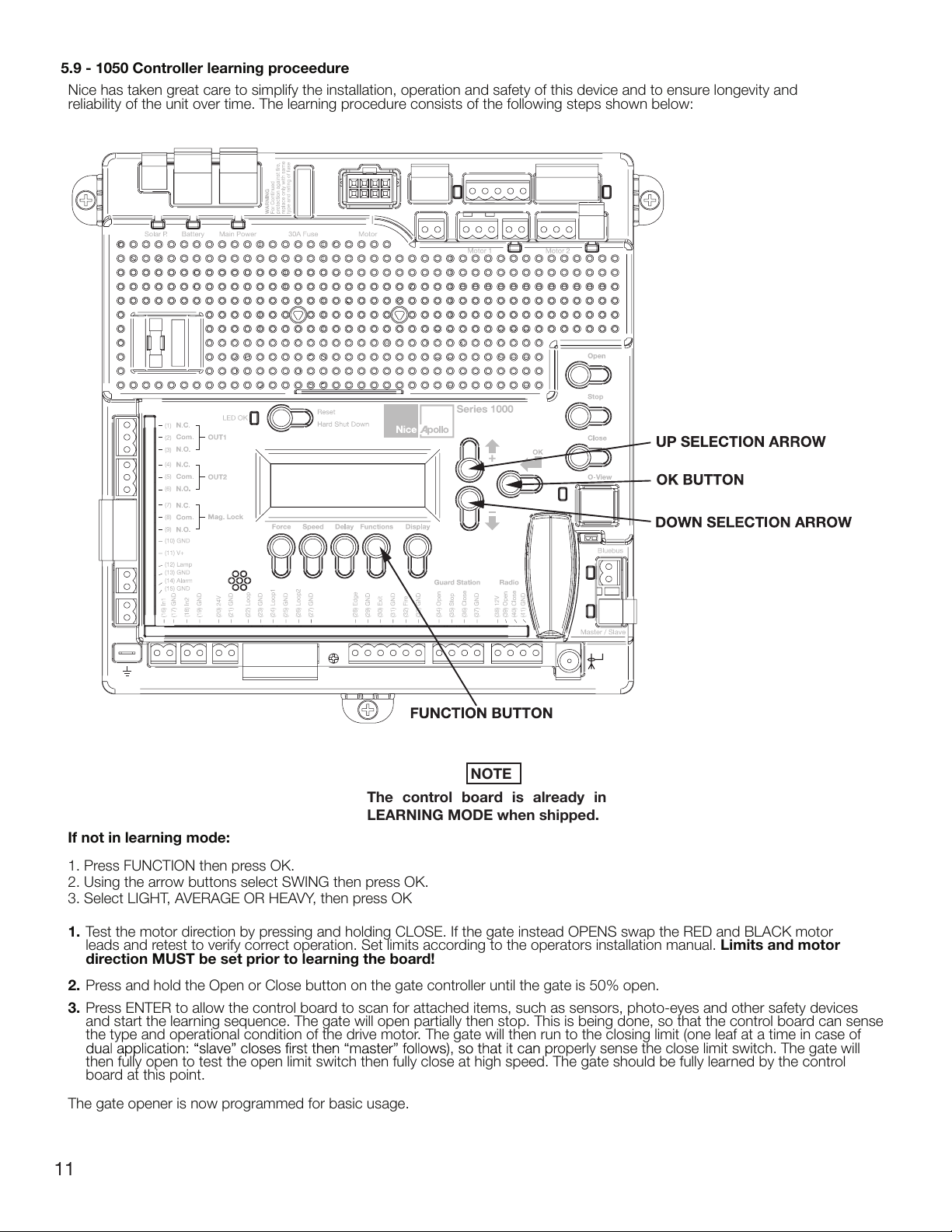
5.9 - 1050 Controller learning proceedure
Nice has taken great care to simplify the installation, operation and safety of this device and to ensure longevity and
reliability of the unit over time. The learning procedure consists of the following steps shown below:
NOTE
control board is already in
The
LEARNING MODE when shipped.
If not in learning mode:
Press FUNCTION then press OK.
1.
2. Using the arrow buttons select SWING then press OK.
3. Select LIGHT, AVERAGE OR HEAVY, then press OK
1. Test the motor direction by pressing and holding CLOSE. If the gate instead OPENS swap the RED and BLACK motor
leads and retest to verify correct operation. Set limits according to the operators installation manual. Limits and motor
direction MUST be set prior to learning the board!
2. Press and hold the Open or Close button on the gate controller until the gate is 50% open.
3. Press ENTER to allow the control board to scan for attached items, such as sensors, photo-eyes and other safety devices
and start the learning sequence. The gate will open partially then stop. This is being done, so that the control board can sense
the type and operational condition of the drive motor. The gate will then run to the closing limit (one leaf at a time in case of
then fully open to test the open limit switch then fully close at high speed. The gate should be fully lear
board at this point.
The gate opener is now programmed for basic usage.
operly sense the close limit switch. The gate will
ned by the control
11
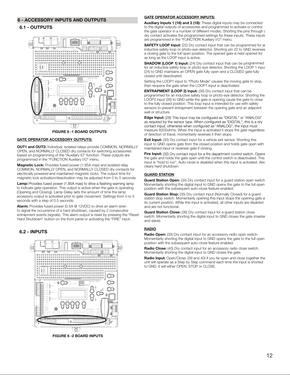
6 - ACCESSORY INPUTS AND OUTPUTS
GATE OPERATOR ACCESSORY INPUTS:
Auxiliary Inputs 1 (16) and 2 (18): These digital inputs may be connected
to the digital outputs of accessories and programmed to activate or contr
ol
the gate operator in a number of different modes. Shorting the pins thr
ough a
dry contact activates the pr
ogrammed settings for these inputs. These inputs
are programmed in the “FUNCTION Auxiliary I/O” menu.
SAFETY LOOP Input:
(22) Dry contact input that can be pr
ogrammed for an
inductive safety loop or photo-eye detector. Shorting pin 22 to GND r
everses
a closing gate to the full open position. The opened gate is held opened for
as long as the LOOP input is active.
SHADOW (LOOP 1) Input:
(24) Dry contact input that can be pr
ogrammed
for an inductive safety loop or photo-eye detector
. Shorting the LOOP 1 input
(24) to GND maintains an OPEN gate fully open and a CLOSED gate fully
closed until deactivated.
Setting the LOOP1 input to “Photo Mode” causes the moving gate to stop,
then r
eopens the gate when the LOOP1 input is deactivated.
ENTRAPMENT (LOOP 2) Input:
(26) Dry contact input that can be
programmed for an inductive safety loop or photo-eye detector
. Shorting the
LOOP2 input (26) to GND while the gate is opening cause the gate to close
to the fully closed position. This loop input is intended for use with safety
sensors to pr
event entrapment between the opening gate and an adjacent
wall or structure.
Edge Input:
measure 8200ohms. When the input is activated it stops the gate regar
dless
of direction of travel, momentarily reverses it then stops.
Exit Input:
(30) Dry contact input for a vehicle exit sensor. Shorting this
input to GND opens gate fr
om the closed position and holds gate open with
maintained input or reverses gate if closing.
Fir
e Input:
the gate and holds the gate open until the contr
ol switch is deactivated. This
input is “hold to run”. Auto-close is disabled when this input is activated. Also
clears hard shutdown.
GUARD ST
ATION
Guard Station Open: (34) Dry contact input for a guar
d station open switch.
Momentarily shorting the digital input to GND opens the gate to the full open
position with the subsequent auto-close feature enabled.
Guar
d Station Stop: (35) Dry contact input (Normally Closed) for a guard
station stop switch. Momentarily opening this input stops the opening gate at
its current position. While this input is activated, all other inputs are disabled
and ar
e not functional.
Guard Station Close: (36) Dry contact input for a guar
d station close
switch. Momentarily shorting the digital input to GND closes the gate (master
and slave).
RADIO
Radio Open: (39) Dry contact input for an accessory radio open switch.
Momentarily shorting the digital input to GND opens the gate to the full open
position with the subsequent auto-close feature enabled.
Radio Close: (40) Dry contact input for an accessory radio close switch.
Momentarily shorting the digital input to GND closes the gate.
Radio Input:
Open/Close: (39 and 40) If you tie open and close together the
unit will operate as a Step by Step command each time the input is shorted
to GND, it will either OPEN, STOP or CLOSE.
FIGURE 6 -1 BOARD OUTPUTS
GATE OPERATOR ACCESSORY OUTPUTS:
OUT1 and OUT2: Individual, isolated relays provide COMMON, NORMALLY
OPEN, and NORMALLY CLOSED dry contacts for switching accessories
based on programming of the “Auxiliary IO” function. These outputs are
programmed in the “FUNCTION Auxiliary I/O” menu.
Magnetic Lock: Provides fused power (1.85A max) and isolated relay
COMMON, NORMALLY OPEN, and NORMALLY CLOSED dry contacts for
electrically powered and maintained magnetic locks. The output time for
magnetic lock activation/deactivation may be adjusted from 0 to 5 seconds.
Lamp:
to indicate gate operation. This output is active when the gate is operating
(Opening and Closing). Lamp Delay sets the amount of time the lamp
accessory output is activated prior to gate movement. Settings from 0 to 5
seconds with a step of 0.5 seconds.
Alarm: Provides fused power (0.5A @ 12VDC) to drive an alarm siren
to signal the occurrence of a hard shutdown, caused by 2 consecutive
entrapment events (signals). This alarm output is reset by pressing the “Reset
Hard Shutdown” button on the front panel or activating the “FIRE” input.
6.1 - OUTPUTS
6.2 - INPUTS
FIGURE 6 -2 BOARD INPUTS
12

6.3 - COMMUNICATION BUSES
On the Slave operator, select Function -> Adv. Settings -> Remote Mst. Slv.
Then select On -> Slave. The r
connector will illuminate.
identical open/close/stop functions in tandem with the Master gate operator.
ed LED associated with the Master/Slave
Programming the plug-in receiver and remote controls Nice
Plug in Receiver: The Nice 433Plug-In Receiver provides up to 15
FIGURE 6.3 COMMUNICATION BUSES
OVIEW
Programming and diagnostic unit which connects directly to the gate
controller and is part of the Nice “Opera” control system. The unit can be
used in “stand-alone” mode via its front-panel keypad, or it may be accessed
via a Bluetooth or cellular-enabled PDA, PC, or Smartphone when used with
the
O-View Software Suite. This unit, when matched with the OVIEW Bluetooth
or
GSM modules, enables remote control and management of the gate
controller. Remote control functions include most of the programming
functions that are available at the front panel LCD on the control board as
well as software updates.
OVBT:
Bluetooth module for OVIEW and the “O-View Software Suite”
application for PC, PDA, or Smartphone for localized wireless control of the
gate controller.
OVBTGSM:
OVIEW and provides cellular phone access through the “O-View Software
Suite” application for PC, PDA, or Smartphone, for wireless local, national,
and international controller of the gate controller.
O-VIEW Software Suite: Provides desktop or Smartphone level control of
as new versions of software are made available.
BLUEBUS ACCESSORIES
MOTB: Moon Touch programmable keypad with secure codes (up to 9
digits per code if required) to control gate opening and closing. Connects to
the 2-wire BlueBUS connector with inexpensive unshielded twisted-pair wire.
MOFB: Photocell transmitter and receiver pair that connects to the 2-wire
BlueBUS connector with inexpensive unshielded twisted-pair wire and is a
31.1 “General Entrapment Protection Provisions”.
MASTER/SLAVE - ONLY USED IN 24V COMMERCIAL OPERATORS
The gate operator includes a two-pin connector designed to link two
separate gate operators together as a Master/Slave pair. The Master/Slave
unshielded twisted-pair wire (Max.100 ft.). All entrapment sensors, switch
inputs, receiver controls, and outputs must be wired to the gate operator
designated as the “Master”. The following procedure outlines the process for
for each operator. See the “Programming Quick Start” procedures in this
manual for a description of the gate lear
On the Master operator, select Function -> Adv. Settings -> Remote Mst. Slv.
Then select On -> Master. The red LED associated with the Master/Slave
connector will illuminate.
Combination
GSM and Bluetooth module that plugs into the
ning process.
ogramming functions for adding or r
built-in pr
controls to/from a gate installation. The following procedures detail the steps
to assign a remote control, add a new remote control, delete a single remote
control, or remove all remote controls from the receiver memory.
Programming the Nice 2-Button or 4-Button Remote Control with the
Nice Plug-In Receiver.
These procedures apply to the Nice wireless remote control. These procedures
assign factory default controls automatically to the remote control.
1. Have a functioning Nice 2-button or 4-button r
installed prior to programming the remote control.
2. Press and hold the button on the side of the Nice receiver until the led
illuminates green on the Nice receiver, then release the button.
3. Within 10 seconds, press and hold any key on the Nice remote control until
the led in the Nice receiver blinks green 3 times, indicating that the Nice is
programmed to control the receiver.
4. After the led on the Nice receiver blinks green 3 times, another 10 second
interval is started to program another Nice remote control if desired. Repeat
step 3 to program the additional Nice remote control. Step 3 may be repeated
as many times as necessary to program all available Nice remote controls.
5. Verify that the Nice remote control(s) can control the gate by pressing one or
more buttons individually on the remote control(s).
Add new remote control to the Nice Plug-In Receiver
A Nice remote control that has been programmed to control a Nice receiver
may be used to create other Nice remote controls for the same receiver. This
procedure needs to be performed within 10 to 20m (30 to 60 feet) of the Nice
receiver, but the Nice receiver does not need to be physically accessed.
1. Press and hold any button on the non programmed Nice remote control for
at least 5 seconds, then release the button, taking note of the button that was
pressed.
2. Press the same button on the programmed Nice remote control three times.
3. Press the same button in step 1 on the non programmed Nice remote control
and release.
4. It is recommended to test the new copy of the Nice remote control with the
assigned gate controller.
NOTE: This procedure will affect all Nice receivers within radio range.
Deleting a Single Nice Remote Control from the Nice Plug-In Receiver
Memory
A Nice remote control that has been programmed to control a Nice receiver may
be removed from the Nice receiver memory without affecting other assigned
remote controls. This procedure needs to be performed at the Nice Plug-In
Receiver with the affected Nice remote control.
1. Press and hold the button on the side of the Nice receiver until the led on
the Nice receiver illuminates green and keep the button pressed. The led will
illuminate after approximately 4 seconds.
2. Press and hold any button on the Nice remote control until the led on the Nice
3. Release the button on the side of the Nice r
4. It is recommended to verify that the non programmed Nice remote control no
longer controls the gate.
emoving Nice wireless remote
emote control with a battery
eceiver.
13

7 - 120VAC POWER WIRING
Table 1 - MAXIMUM RUN (FT) PER WIRE GAUGE
110V AWG
MAX RUN (ft)
14 12
10 8 6 4
180 280 460 700 1150 1800
Deleting all Nice transmitters from the Nice Plug-In Receiver Memory.
All pr
ogrammed remote controls may be removed from the Nice plug
in receiver memory . This procedures need to be performed at the gate
controller.
1. Press and hold the button on the side of the Nice receiver until the led on
the Nice receiver illuminates green and keep the button pressed.
2. Watch the led and on the receiver and verify the following sequence in the
led.
3. Within 4 seconds after pressing the button (approx.) the green led
illuminates.
4. Within 8 seconds after pressing the button (approx.) the green led turns
off.
5. Within 12 seconds after pressing the button (approx.) the green led starts
6. EXACTLY the 3
rd
release the button on the Nice receiver.
7. I
t is recommended to test the Nice remote controls, if available, with Nice
plug in receiver to verify that it no longer affects the gate controller.
• Disconnect power to the gate operator by manually opening its dedicated
circuit breaker before making any mechanical or electrical adjustments.
• Use a 20 Amp dedicated circuit breaker for each installed gate operator.
• Open dedicated circuit breaker supplying power to this gate operator
installation of this gate operator.
•
• Run individual circuits in separate U.L. listed conduits. Do not combine
high voltage (120VA
C) power wiring and low voltage (+12VDC to +24VDC)
control wiring in the same conduits.
• Use the information in table 1 to determine high voltage wire size
requirements. The distance shown in the chart is measured in feet from the
operator to the power source. If power wiring is greater than the maximum
distance shown, it is recommended that a service feeder be installed.
When large gauge wire is used, a separate junction box must be installed
for the operator connection. The wire table is based on stranded copper
wire. Wire run calculations are based on a 110 VAC power source with a
3% voltage drop on the power line, plus an additional 10% reduction in
distance to allow for other losses in the system.
The gate operator system should be grounded through the earth ground
in the AC mains wiring system (GREEN WIRE). This ground connection will
prevent dangerous currents from appearing on the metal control box, the
actuator, or the gate itself.
DO NOT WIRE AC MAINS POWER TO THE METAL CONTROL BOX
WITHOUT AN EARTH GROUND CONNECTION!
8 - SOLAR PANEL CHART
Daily cycles 1-10 1-20 1-40 1-60 1-80 80+
5 watt solar panel
*
10 watt solar panel
*
20 watt solar panel
(requires regulator)
*
30 watt solar panel
(requires regulator)
*
40 watt solar panel
(requires regulator)
*
1.5 amp battery
charger
*
10 amp battery
charger
*
Note: Double the amount of solar wattage for dual gate operators
Nice Apollo operators with the 1050 board that are used in solar applications
need to be put into “Standby” mode.
To do this, press Functions – scroll to #8 “Standby” – Press OK – Scroll to
desired amount of time before system enters Standby mode – Pr
ess OK. Once
this is done, the operator will enter a Standby mode after the set time when the
operator is not moving or in the auto-close countdown.
Things to note in Standby:
1.
Display will be off and only a “heartbeat” will be present at the LED OK
2. Voltage at #20 (24 volts) and #38 (12 volts) will turn off - DO NOT
CONNECT ENTRY OR EXIT DEVICES HERE
3. BlueBus connection is non functional
4. Master/Slave syncing is non functional (used for commercial operators
only)
Connection of the solar panel(s) may be made at the top left corner of the
board at “Solar P” (regulated charging to the “Battery” via the controller in the
board) – note that the maximum output of the regulator in the 1050 board is
1.5A. If the installation requires larger than a 30W solar panel – an off-board
regulator should be used and connected directly to the battery.
DO NOT WIRE AC POWER TO THE 1050 CONTROL BOARD!
THE CONTROL BOARD OPERAT
ES ON 10 - 35 VDC ONLY!
This section intended for residential systems where a 120VAC
transformer will be used
To reduce the risk of SEVERE INJURY or DEATH:
FIGURE 7-1 EQUIPMENT SAFETY WARNINGS
This Apollo Gate Operator is 12 Volt DC (Direct Current) powered. A 12 Volt
sealed battery (33 ampere hour minimum for AC charged systems, 70 ampere
hour minimum for solar charged systems) with connecting posts located on the
top is recommended.
The following table should be used as a guide for capacity of operation of
operators only, additional options and accessories may reduce the daily usage.
Please note that the charge capability of solar panels will vary with different
geographical locations.
14

9 - OPTIONAL INPUTS
32 FIRE
33 GND
contact must be shorted to ground through a switch to open the gate.
The FAIL SAFE connector which is shorted at the factory with a jumper
(Normally
Closed NC), may be wired in parallel with the Fire input to release the
a power failure. Opening the FAIL SAFE contacts allows the gate to be
pushed open by hand.
9.4 - EXIT & EDGE INPUTS WIRING DIAGRAM
28 EDGE
29 GND
30 EXIT
31 GND
(NC or NO) input. The EDGE sensor input is intended for ANSI/UL 325 listed
gate edge sensors to protect against entrapment and hazardous pinch points
along the moving edge of the closing gate. The EXIT sensor input is provided
to activate to open the gate, or re-open a closing gate, upon sensing an exiting
vehicle.
9.2 - MAGNETIC LOCK CONNECTION
7 NC
8 Com (Common)
9 NO
10 GND
11 V+ (Voltage is determined by incoming power supply)
This connection is used to install the magnetic lock. In this instance a gate
can be locked magnetically to prevent a forced opening. Consult lock
34 OPEN
35 STOP
36 CLOSE
37 GND
Wi
th the Guard Station switches installed, the user can operate the gate
by pushing the r
espective buttons for the command that is desired. Gate
Open and Close ar
e controlled by NORMALLY OPEN (NO) and Stop is
cont
rolled by NORMALLY CLOSED (NC) momentary switches.
NOTE:
If the guard station inputs are not used STOP (35) and GND (37)
need to be tied together
Exit Device
9.1 - FIRE DEPARTMENT CONNECTION
FIGURE 9 -1 FIRE DEPARTMENT INPUT
FIGURE
9 -2 MAGNETIC LOCK WIRING (EXAMPLE)
9.3 - GUARD STATION
FIGURE 9 -3 GUARD STATION INPUTS
FIGURE 9 - 4 EXIT AND EDGE INPUTS
15

10-
RADIO RECEIVER CONNECTION (THIRD PARTY)
38 12V
39 OPEN
40 CLOSE
41 GND
The customer supplied radio receiver allows the gate operator to be operated
via remote, such as wireless key-card readers or user remote controls.
Connecting the Open (39) and Close (40) pins together with a receiver
to control the gate in the following sequence:
Press - Gate Open
Press - Gate Stop
Press - Gate Close
Press - Gate Stop
11 - INSPECTION AND OPERATION
Proper inspection of all equipment is required to ensur e continuous
functionality, safety and to ensure r
eliable operation in all weather conditions.
Inspect electrical assemblies and wiring installations for damage, general
condition, and proper functioning to ensure the continued satisfactory
operation of the electrical system. Adjust, repair, overhaul, and test electrical
equipment and systems in accordance with the recommendations and
procedures in the gate operator system and/or component manufacturer’s
maintenance instructions.
Replace components of the electrical system that are damaged or defective
with identical parts, with manufacturer’s approved equipment, or its
equivalent to the original in operating characteristics, mechanical strength,
for and checks to be performed are listed below:
12V Power
Normally Open
Common
Ground
FIGUR E 10-1 RADIO RECEIVER
16
Damaged, discolored, or overheated equipment, connections, wiring,
bearing caps and installations.
Excessive heat or discoloration at high current carrying connections.
(look for bluing or heat affected metal).
Misalignment if electrically driven equipment. (Causes strain on
pulley assemblies and bearings).
Poor electrical bonding (broken, disconnected or corroded bonding
strap) and grounding, including evidence of corrosion.
Dirty equipment and connections. Clean equipment and connections.
Improper, broken, inadequately supported equipment, wiring and
conduit, loose connections of terminals, and loose ferrules.
Poor mechanical or weld joints. Broken welds.
Condition of circuit breaker and fuses. Ensure that they are of the
correct type and amperage.
Insufficient clearance between exposed current carrying parts
and ground or poor insulation of exposed terminals. All exposed
connections must be covered (prevent arcing between exposed
parts, and electrical shock).
Broken or missing wire, connectors, etc.
Operational check of electrically operated equipment such as
motors, inverters, generators, batteries, lights, protective devices,
etc. Ensure proper functionality of all systems during inspections.
Ensure safety placards and warning signs are present as specified
within this document. Ensure proper functionality of all safety devices
as specified. Non-functioning or malfunctioning safety devices should
be replaced immediately.

12 - GENERAL LAYOUT AND SAFETY ACCESS
Entrapment Pro
Outside
Photo 2 Photo 2
tection Inputs - Typical Installation Diagram Utilizing Loop Sensors and Photocells
Loop (Safety)
Gate
4’ Min. from closed gate
4’ Min. from closed gate
Loop (Shadow
4’ Min. from open gate
)
Loop (Safety)
Loop (Exit)
FIGURE 12 -1 LAYOUT FOR IN-GROUND LOOPS
Entrapment Protection Inputs - Typical Installation Diagram Utilizing Photocells
Outside
Gate
Photo
Photo 2 Photo 2
Photo 1
17
12 -2 LAYOUT FOR PHOTOCELLS
FIGURE

SECTION 13 - ACCESSORIES AND SENSORS
EXTERNAL ENTRAPMENT PROTECTION
Non-contact and contact sensors must be installed individually or in combination with each other to provide external entrapment pr
otection.
Care should be exercised to reduce the risk of nuisance tripping, such as when a vehicle trips the sensor while the gate is still moving, and one or mo
contact sensors shall be located where the risk of entrapment or obstruction exists, such as the perimeter reachable by a moving gate or barrie
A hardwired contact sensor shall be located and its wiring arranged so that the communication between the sensor and the gate o
perator is not subjected to
mechanical damage.
A wir
eless contact sensor such as one that transmits radio f
requency (RF) signals to the gate operator for entrapment pr
otection functions shall be located
where the transmission of the signals are not obstructed or impeded by building structures, natural landscaping or similar obstruction.
DURING INSTALLATION
• DISCONNECT POWER at the control panel before making any electric service power connection.
• Be aware of all moving parts and avoid close proximity to any pinch points.
• Know how to operate the manual release.
• Adjust the unit to use the minimum force required to operate the gate smoothly even during mid-travel reversing.
• Place controls a minimum of 8 feet away from the gate so that the user can see the gate and operate controls but cannot touch the gate or gate operator
while operating the controls.
• Warning signs must be placed on each side of the gate or in high-visibility areas to alert of automatic gate operations.
18
Moving Gate Can Cause
Serious Injury or Death.
Persons are to keep clear! The gate is able to be moved without prior warning.
Do not allow children to operate gate or play in gate area.
This entrance is for vehicles only. Pedestrians must use separate entrance.
Persons are to read the owner's manual and safety instructions.

14 - MANUAL RELEASE/MANUAL OPERATION
Manual Release
1. Lift rubber key cover and insert
key into lock and ro
tate 90°
clockwise.
2. Lift handle
Safety Manual Lock
In Released Position
FIGURE 13 -2 MANUAL RELEASE
RUBBER
KEY
COVER
3. Operator is now in Manual
Mode.
90°
Manual Release Disengage
Close handle
1.
2.
Rotate key 90° counterclock wise
and remove key.
Manual Release
In Locked Position
19
3. Replace rubber key cover.
4. Operator is now in
Automatic Mode.
FIGURE 13 -3 MANUAL RELEASE DISABLE

• Slow Down – Close: Sets the % of gate opening when the gate begins
deceleration to the fully close position.
•
Partial: Sets the point in the % of gate opening when the gate begins when
given a PARTIAL command.
Auxiliary Inputs: Auxiliary inputs IN AUX1 (16) and IN AUX2 (18) can be
programmed with one of the following options:
• No program No Function used
• OPEN the Gate
• CLOSE the Gate
• STEP Cycling Step (Open-Stop-Close-Stop)
• PARTIAL opening
• PARTIAL 1 Partial Opening 1 (open one leaf in dual gate applications)
• STOP the gate and Auto-closing
• HOLD TO OPEN Input must be maintain active for Opening
• HOLD TO CLOSE Input must be maintain active for Closing
• FIRE Reset Hard Shut Down and Open the Gate
• TIMER 1 Start Count Down TIMER1
• TIMER 2 Start Count Down TIMER2
• PHOTO Photocell PHOTO input: reverse to opening when closing
• PHOTO1 Photocell PHOTO1 input: Stop Gate when activated
• PHOTO2 Photocell PHOTO2 input: reverse to closing when opening
• SHADOW Loop input: prevent closing gate when completely open
• LOCK system from other command (only STEP H overrides the lock)
• UNLOCK Unlock the system if locked
• OPEN and LOCK Open the Gate and inhibit further commands (except STEP
H)
•
CLOSE and LOCK Close the Gate and inhibit further commands (except
STEP H)
• OPEN and UNLOCK Open the Gate and un-inhibit further commands
• CLOSE and UNLOCK Close the Gate and un-inhibit further commands
• STEP H Command high priority Step cycling (open-stop-close-stop)
Auxiliary Outputs:
Auxiliary outputs OUT AUX1 (1,2,3,) and OUT AUX2
(4,5,6,) can be programmed with one of the following options:
• NO PROGRAM Output not used
• OPEN Output is activated when Gate is open
• CLOSE Output is activated when Gate is closed
• MOVING Output is activated when Gate is moving
• TIMER 1 Output is activated when TIMER1 is counting down
• TIMER 2 Output is activated when TIMER2 is counting down
Radio Channel: For the Plug-in On board Receiver
, 15 radio channels may be
programmed with one of the following options:
•
NO PROGRAM
• OPEN (Default CH. 2)
• CLOSE
• STEP (Default CH. 1)
• PARTIAL
• PARTIAL 1
• STOP
• HOLD TO OPEN
• HOLD TO CLOSE
• TIMER 1
• TIMER 2
• PHOTO
• LOCK
• UNLOCK
• OPEN and LOCK
• CLOSE and LOCK
• OPEN and UNLOCK
• CLOSE and UNLOCK
• STEP H
• TOGGLE & LATCH
Timers: Set time for count down timers Timer 1 and Timer 2. Settings
between 1 second and 9 hours in 1 second increments.
Events: Up to 8 weekly events (EV1 through EV8) can be pr
ogrammed and
15 - 1050 PROGRAMMING
15.1 - FOR
CE
Static: Set sensitivity to constant force on a scale of 1 to 10 (1 being the
most sensitive).
Dynamic
: Set sensitivity of sudden impact for
ce to the moving gate on a
scale of 1 to 10 (1 being most sensitive).
ESC: Exit the FORCE menu.
15.2 - SPEED
Max: Sets the limit of maximum allowed gate speed on a scale of 20% to
100% (20% being the lowest setting).
Standard
: Sets the limit of the gate speed during normal movement (not soft
start/stop) on a scale of 20% to MAX (20% being the lowest setting).
Low
:
Sets the limit of the gate speed while in LEARNING mode and when
moving in SLOW, on a scale of 20% to 100% (20% being the lowest setting).
Slowdown: Set gate speed when going into approaching the open or close
limits on a scale of 20% to 100% (20% being the lowest setting).
15.3 - ACCELERATION
Max: Sets the limit of gate acceleration when reversing the gate after an
obstacle has been detected by the UL/Edge or current sense featur
e (Force).
Settings from 3 to 10, with 10 being the highest rate of gate acceleration. *
Standard:
Sets the limit of the gate acceleration in normal operation.
Settings from 1 to MAX, with MAX being the highest rate of gate acceleration.
* *TO PREVENT DAMAGE TO THE GATE OR THE CONTROLLER USE
LOWER ACCELERATION SETTINGS FOR HEAVIER GATES.
ESC: Exit the SPEED menu.
15.4 - DELAY
Auto Close:
Sets the timeout before the gate closes automatically from the
fully open position. Settings from 0 (off) to 90 seconds. Setting this to 0 will
disable the auto close timer.
Slave: Sets the delay for opening the slave gate leaf in a Master/Slave (Motor
1 and Motor 2 operation), (dual gate) system. Settings from 0 to 5 seconds
with a step of 0.5 seconds.
Lamp/Strobe:
Sets the amount of time the Lamp accessory output is
activated prior to gate movement. Settings from 0 to 5 seconds with a step
of 0.5 seconds.
Lock: Sets the amount of time the Magnetic Lock accessory output is
activated to disable the lock when opening the gate. Settings from 0 to 5
seconds with a step of 0.5 seconds.
Run Time:
Sets the maximum run time for the gate. Used in case the gate
doesn’t reach its limits. Settings from 15 to 120 seconds with a step of 1
second.
ESC: Exit the DELA
Y menu.
15.5 - FUNCTION
Learn
: Puts the gate operator into learning mode for a Swing or Slide gate,
and Blue BUS peripherals. Learning mode for a Swing or Slide style gate
involves selecting the gate type (Light, A
verage, Heavy), then fully opening
and closing the gate to sense the limits. Selecting the gate type selects
pre-calculated values for the FORCE, SPEED, and ACCELERATION settings.
Learning the Blue BUS peripherals enables the gate operator to discover and
integrate accessory devices like Blue BUS access control and safety devices.
Positions
at which deceleration occurs.
• Slow Down – Open: Sets the point in the % of gate opening when the gate
begins deceleration to the fully open position.
20

be assigned to any combination of days of the week (Monday through
Sunday). Events that a
re already programmed into the system may be
suspended temporarily
, or removed permanently from memory. The following
actions can be assigned to events:
• No pr
ogram
• Open
• Close
• Partial
• Partial1
• AxOut1On
• AxOut1 Of
f
• AxOut2 On
• AxOut2 Of
f
• Open and Lock
• Close and Lock
• Open and Unlock
• Close and Unlock
•
Timer 1
•
Timer 2
To
program weekly events EV1 through EV8, perform the following
steps:
1.
P ress FUNCTION -> Events.
2.
P ress and hold OK to display EV1 (display will blink “EV1”).
3.
P ress UP or DOWN to toggle between events, then press OK to make a
selection. The display changes to hours.
4.
P ress UP or DOWN to toggle between hours, then press OK to make a
selection. The display changes to minutes.
5
. P ress UP or DOWN to toggle between minutes, then press OK to make a
selection. The display changes to individual days of the week.
6.
P ress UP or DOWN to toggle between days of the week. Press OK to
toggle between ON and OFF for each day of the week. Continue toggling
through the days of the week until ESC is displayed. Pr
ess OK to advance
to the next event.
7.
R epeat step 2 through 6 for event EV2 through EV8.
To
temporarily suspend one or more weekly events (EV1 through EV8),
perform the following steps:
1.
P ress FUNCTION -> Events.
2.
P ress OK quickly to display EV1 active days.
3.
P ress OK quickly again to display “Suspend”. Event EV1 is now
suspended and will not run until re-enabled.
4.
P ress UP or DOWN to toggle through the events EV1 – EV8 and repeat
steps 2 through 3 to suspend or enable other weekly events.
Charger
: A battery charger is built-in with the Control board
for use with a
backup battery
. The charger may be manually programmed for customized
automatically compensates for temperatur
e and current during the charging
pr
ocess. The following parameters are available for programming the battery
charger:
• Charger On/Of
f
• Select Max curr
ent for charging (from 0.1A to 1.5A step 0.05A)
• Cycling
Time (1 second off charging every cycling time)
• Auto (best charge considering temperatur
e)
Standby:
Programs the timeout for the gate operator to go into low power
standby mode. Low power standby is Settings
from 5 to 120 seconds, or
may be disabled with “OFF”. During low power standby th
ere is no data
displayed on the gate operator LCD and it consumes a minimum amount of
power to extend the life of the backup battery
. All the outputs are switched off
and the LED OK blinks to show this standby status of the system.
Advance Settings:
The following settings are available for customizing the
gate operator as r
equired by the customer’s installation requirements:
•
Set Language (English Spanish French)
•
Set clock 12H/24H
•
Set LCD Contrast
•
Direction Motor (Changes main motor direction) (Can only be performed in
learn mode)
•
Auto Close Option (Allows auto close timer to close from any open position)
•
Exit Option (Disables free exit input when partially open)
• Set Anti-tailgate (Closes gate immediately after vehicle has clear
ed safety
sensors)
• Select inputs LOOP or PHOTO
• Select UL/EDGE input type (NO, NC, Analog)
• Select Master / Slave Motor1 or Motor2
• Activate link for remote Master/Slave (Enables control of an additional gate
operator board)
•
Power Fail Open (Opens gate automatically on batter backup power if main AC
power input loss is detected)
•
Motor 12V (For
ces motor contro
l voltage to +12VDC even if the supply voltage
varies from +9.5VDC up to +35VDC)
•
Set Virtual Encoder (Used for motors without built-in encoders)
Default:
This setting gives the installer/user the option of returning some or all
settings of the gate operator to the original factory settings:
• System settings
• Radio Channel settings
• Event settings
• Charger settings
ESC: Exit the FUNCTION menu.
15.6 - DISPLAY
ESC: Exit the DISPLAY menu.
Info
: Displays the manufactur
er name, product name/model, software versions,
and serial number.
Clock: Displays the calendar date and time in the real time clock. Pressing and
holding the “OK” button for 5 seconds enables the date and time settings to be
updated manually.
Main Volt: Displays the gate operator main control voltage in volts DC.
Battery Volt: Displays the gate operator backup battery voltage in volts DC.
Sun Volt: Displays the solar panel input voltage in volts DC.
Motor Volt: Displays the voltage at the motor in volts DC.
UL Volt: Displays the voltage at the UL/Edge sensor input in volts DC.
Temperature: Displays the temperature of the gate controller board in degr
ees
Centigrade or Fahr
enheit (press OK and hold 5 seconds to change scale).
Service: The following information is recor
ded and viewable about the operating
history of the gate:
• To
tal: Displays the total number of open-close cycles (non- Settings ).
• Partial: Display the total number of partial cycles. Reset by pressing the “OK”
button for several seconds.
• Maint. Display the number of cycles before service is required. Settings from
1000 to 50000 cycles in increments of 1000 cycles.
Motor: Displays the Motor position, voltage, and current.
Motor 1: Displays the Motor1 position, voltage, and current.
Motor 2: Displays the Motor2 position, voltage, and current.
Charger
: Displays the battery charger voltage and curr
ent.
Last Reset: Displays the code for diagnostic review. Used for diagnostic and
troubleshooting.
ESC: Exit the DISPLAY menu.
21
www.ApolloGateOpeners.com
sales@apollogateopeners.com
Phone: 800.878.7829
Fax: 330.650.9004
 Loading...