

Page 1

Nice
SO2000
Garage door opener
EN - Instructions and warnings for installation and use
Page 2

ENGLISH
Translation of the original instructions in full
CONTENTS
1 GENERAL SAFETY WARNINGS AND PRECAUTIONS . . . . .2
1.1 IMPORTANT INSTALLATION INSTRUCTIONS . . . . . . . . . . . 2
1.2 IMPORTANT SAFETY INSTRUCTIONS . . . . . . . . . . . . . . . . . 3
2 PRODUCT DESCRIPTION AND INTENDED USE . . . . . . . . . 4
2.1 List of constituent parts . . . . . . . . . . . . . . . . . . . . . . . . . . . . . 4
3 INSTALLATION . . . . . . . . . . . . . . . . . . . . . . . . . . . . . . . . . . . . . 5
3.1 Pre-installation checks . . . . . . . . . . . . . . . . . . . . . . . . . . . . . 5
3.2 Product usage limits . . . . . . . . . . . . . . . . . . . . . . . . . . . . . . . 5
3.2.1 Product durability . . . . . . . . . . . . . . . . . . . . . . . . . . . . . . . 5
3.3 Product identification and overall dimensions . . . . . . . . . . . . 6
3.4 RECEIPT OF THE PRODUCT . . . . . . . . . . . . . . . . . . . . . . . . 6
3.5 Pre-installation works . . . . . . . . . . . . . . . . . . . . . . . . . . . . . . 7
3.6 Installing the gearmotor . . . . . . . . . . . . . . . . . . . . . . . . . . . . . 8
3.7 Manually unlocking and locking the gearmotor . . . . . . . . . . . 9
4 ELECTRICAL CONNECTIONS . . . . . . . . . . . . . . . . . . . . . . . . 9
4.1 Preliminary checks . . . . . . . . . . . . . . . . . . . . . . . . . . . . . . . . 9
4.2 Wiring diagram and description of connections . . . . . . . . . . 10
4.2.1 Wiring diagram . . . . . . . . . . . . . . . . . . . . . . . . . . . . . . . . 10
4.2.2 Description of connections . . . . . . . . . . . . . . . . . . . . . . . 10
4.3 Addressing of devices connected with the BlueBUS system 11
4.3.1 FT210B photosensor . . . . . . . . . . . . . . . . . . . . . . . . . . . 12
5 FINAL CHECKS AND START-UP. . . . . . . . . . . . . . . . . . . . . . 12
5.1 Power supply connection . . . . . . . . . . . . . . . . . . . . . . . . . . 12
5.2 Device learning . . . . . . . . . . . . . . . . . . . . . . . . . . . . . . . . . . 12
5.3 Learning of the door opening and closing positions. . . . . . . 12
5.4 Checking the door movement . . . . . . . . . . . . . . . . . . . . . . . 14
5.5 Connecting other devices . . . . . . . . . . . . . . . . . . . . . . . . . . 14
6 TESTING AND COMMISSIONING. . . . . . . . . . . . . . . . . . . . . 14
6.1 Testing . . . . . . . . . . . . . . . . . . . . . . . . . . . . . . . . . . . . . . . . 15
6.2 Commissioning . . . . . . . . . . . . . . . . . . . . . . . . . . . . . . . . . . 15
7 PROGRAMMING . . . . . . . . . . . . . . . . . . . . . . . . . . . . . . . . . . 16
7.1 Using the programming buttons . . . . . . . . . . . . . . . . . . . . . 16
7.2 Level 1 programming (ON-OFF) . . . . . . . . . . . . . . . . . . . . . 17
7.2.1 Level 1 programming procedure . . . . . . . . . . . . . . . . . . . 17
7.3 Level 2 programming (adjustable parameters) . . . . . . . . . . . 18
7.3.1 Level 2 programming procedure . . . . . . . . . . . . . . . . . . . 18
7.4 Programming the direction . . . . . . . . . . . . . . . . . . . . . . . . . 20
7.5 Resetting the encoder position . . . . . . . . . . . . . . . . . . . . . . 20
7.6 Special functions . . . . . . . . . . . . . . . . . . . . . . . . . . . . . . . . . 20
7.6.1 “Always open” function . . . . . . . . . . . . . . . . . . . . . . . . . 20
7.6.2 “Move anyway” function . . . . . . . . . . . . . . . . . . . . . . . . . 20
7.6.3 “Maintenance notice” function . . . . . . . . . . . . . . . . . . . . 20
7.7 Verifying the number of manoeuvres completed . . . . . . . . . 21
7.8 Manoeuvre counter resetting . . . . . . . . . . . . . . . . . . . . . . . . 21
7.9 Memory deletion . . . . . . . . . . . . . . . . . . . . . . . . . . . . . . . . . 21
8 TROUBLESHOOTING GUIDE . . . . . . . . . . . . . . . . . . . . . . . . 22
8.1 Troubleshooting . . . . . . . . . . . . . . . . . . . . . . . . . . . . . . . . . 22
8.2 Anomaly log . . . . . . . . . . . . . . . . . . . . . . . . . . . . . . . . . . . . 23
8.3 Signalling through warning light . . . . . . . . . . . . . . . . . . . . . . 23
8.4 Signals on the control unit . . . . . . . . . . . . . . . . . . . . . . . . . . 24
9 FURTHER DETAILS (Accessories) . . . . . . . . . . . . . . . . . . . . 26
9.1 Modifying the STOP input configuration . . . . . . . . . . . . . . . 26
9.2 Alarm system . . . . . . . . . . . . . . . . . . . . . . . . . . . . . . . . . . . 26
9.3 Connecting an SM-type radio receiver . . . . . . . . . . . . . . . . 26
9.4 Connecting and installing the back-up battery . . . . . . . . . . . 27
9.5 Connecting the Oview programmer . . . . . . . . . . . . . . . . . . . 28
9.6 Connecting the Solemyo solar energy system . . . . . . . . . . . 29
10 PRODUCT MAINTENANCE . . . . . . . . . . . . . . . . . . . . . . . . . . 30
11 PRODUCT DISPOSAL . . . . . . . . . . . . . . . . . . . . . . . . . . . . . . 30
12 TECHNICAL SPECIFICATIONS. . . . . . . . . . . . . . . . . . . . . . . 31
INSTRUCTIONS AND WARNINGS FOR THE USER. . . . . . 33
1
1 GENERAL SAFETY WARNINGS AND PRECAUTIONS
1.1 IMPORTANT INSTALLATION INSTRUCTIONS
a
PRECAUTIONS
WARNING – To reduce the risk of severe
injury or death:
• READ AND FOLLOW ALL INSTALLATION INSTRUCTIONS.
• Install only on a properly operating and balanced
garage door. An improperly balanced door has the
potential to inict severe injury.
– For vertically sliding doors: have a qualied service
person make repairs to cables, spring assemblies,
and other hardware before installing the opener.
– For horizontally sliding doors: have a qualied
service person make repairs and hardware adjustments before installing the opener.
• Remove all pull ropes and remove, or make inoperative, all locks connected to the garage door before installing the operator.
• For “Commercial/industrial door operators (or
systems)”: moving parts capable of causing injury
to persons or employs a motor deemed indirectly
accessible by virtue of its location above the oor
shall include:
– a) Install the door operator at least 2.44 m (8 ft) or
more above the oor; or
– b) If the operator must be installed less than 2.44
m (8 ft) above the oor, then exposed moving parts
must be protected by covers or guarding, provided
by the operator manufacturer; or
– b) If the operator must be installed less than 2.44
m (8 ft) above the oor, then exposed moving parts
must be protected by covers or guarding, provided
by the operator manufacturer; or
• Where possible, install the door operator 2.14 m (7
ft) or more above the oor. For products having an
emergency release, mount the emergency release
within reach, but at least 1.83 m (6 ft) above the
oor and avoiding contact with vehicles to avoid
accidental release.
• Do not connect the door operator to source of
power until instructed to do so.
• Locate the control button: (a) within sight of the
door, (b) at a minimum height of 1.53 m (5 ft) above
oors, landings, steps or any other adjacent walking surface so small children are not able to reach
it, and (c) away from all moving parts of the door.
• Install the Entrapment Warning Label next to the
control button in a prominent location. Install the
Emergency Release Marking. Attach the marking
on or next to the emergency release.
GENERAL SAFETY WARNINGS AND
2 – ENGLISH
Page 3

• After installing the opener, the door must reverse
when it contacts a 38-mm (1-1/2-inch) high object
(or a 2 by 4 board laid at) on the oor.
• For products having a manual release, instruct the
end user on the operation of the manual release.
• Only enable [+] feature when installed with a sectional door.”, where + is the unattended operation
function.
• This operator not equipped for permanent wiring.
Contact licensed electrician to install a suitable receptacle if one is not available.
• Before commencing the installation, check the “Product
technical specications”, in particular whether this product is suitable for automating your guided part. Should
it not be suitable, do NOT proceed with the installation.
• The product cannot be used before it has been commissioned as specied in the “Testing and commissioning” chapter.
• Before proceeding with the product’s installation, check
that all the materials are in good working order and suited to the intended applications.
• ATTENTION! In order to avoid any danger from
inadvertent resetting of the thermal cut-off device, this appliance must not be powered through
an external switching device, such as a timer, or
connected to a supply that is regularly powered or
switched off by the circuit.
• The system’s power supply network must include a disconnection device (not supplied) with a contact opening
gap permitting complete disconnection under the conditions envisaged by Overvoltage Category III.
• Handle the product with care during installation, taking
care to avoid crushing, denting or dropping it, or allowing contact with liquids of any kind. Keep the product
away from sources of heat and naked ames. Failure
to observe the above can damage the product, and
increase the risk of danger or malfunction. Should this
happen, stop installation immediately and contact Customer Service.
• The manufacturer declines all liability for damages to
property, objects or people resulting from failure to observe the assembly instructions. In such cases, the warranty for material defects shall not apply.
• The weighted sound pressure level of the emission A is
lower than 70 dB(A).
• Before working on the system (maintenance, cleaning),
always disconnect the product from the mains power
supply.
• Inspect the system frequently, in particular the cables,
springs and supports to detect any imbalances and
signs of wear or damage. Do not use the product if it
needs to be repaired or adjusted, because defective installation or incorrect balancing of the automation can
lead to injuries.
• The packing materials of the product must be disposed
of in compliance with local regulations.
• The product must not be installed outdoors.
• Prior to installing the drive motor, check that the door
is in good working order, correctly balanced and that it
opens and closes properly.
• Prior to installing the motor, remove all unnecessary cables or chains and deactivate any equipment – such as
locking devices – not required for motorised operation.
• Check that there are no points where people could get
trapped or crushed against xed parts when the door
is fully open or closed; if there are, arrange adequate
protective measures for these parts.
• After installation, make sure that the motor prevents or
stops opening of the door when the latter is loaded with
a 20-kg weight secured to the centre of its bottom edge
(for drive motors that can be used with doors having
opening widths exceeding 50 mm).
• After installation, make sure that the mechanism is properly adjusted and that the motor reverses when the door
collides with a 38mm (1inch 1/2) -tall object placed on
the ground (for drive motors incorporating a trapping
safety system that intervenes when the bottom edge of
the door encounters an obstacle).
• Following installation, check and ensure that no door
parts obstruct public roadways or pavements.
1.2 IMPORTANT SAFETY INSTRUCTIONS
WARNING – To reduce the risk of severe
a
injury or death:
• READ AND FOLLOW ALL INSTRUCTIONS.
• Never let children operate or play with door controls. Keep the remote control away from children.
• Always keep the moving door in sight and away
from people and objects until it is completely
closed. NO ONE SHOULD CROSS THE PATH OF
THE MOVING DOOR.
• For vertically moving doors: NEVER GO UNDER A
STOPPED, PARTIALLY OPEN DOOR.
• For horizontally moving doors: NEVER GO
THROUGH A STOPPED, PARTIALLY OPEN DOOR.
• Test door opener monthly. The garage door MUST
reverse on contact with a 38-mm (1-1/2-inch) high
object (or a 2 by 4 board laid at) on the oor. After adjusting either the force or thelimit of travel,
retest the door opener. Failure to adjust the opener properly increases the risk ofsevere injury or
death.
ENGLISH – 3
Page 4

• For vertically moving doors for products having
an emergency release, when possible, use the
emergency release only when the door is closed.
Use caution when using this release with the door
open. Weak or broken springs are capable of increasing the rate of door closure and increasing
the risk of severe injury or death.
• KEEP GARAGE DOORS PROPERLY BALANCED.
See user’s manual. An improperly balanced door
increases the risk of severe injury or death.
– For vertically moving doors: have a qualied ser-
vice person make repairs to cables, spring assemblies, and other hardware.
– For horizontally moving doors: have a qualied
service person make repairs and hardware adjustments before installing the opener.
• For operator systems equipped with an unattended operation feature, the following statement shall
be included: “This operator system is equipped
with an unattended operation feature. The door
could move unexpectedly. NO ONE SHOULD
CROSS THE PATH OF THE MOVING DOOR.”
• SAVE THESE INSTRUCTIONS.
• Be careful when activating the manual unlocking device
(manual manoeuvre), as an open door may fall suddenly
due to weak or broken springs, or if it is unbalanced.
• If the power cable is damaged, it must be replaced by
the manufacturer or by an appointed servicing company
or similarly qualied person in order to prevent any form
of risk.
2
2 PRODUCT DESCRIPTION AND INTENDED USE
SO2000 is an electromechanical actuator for automating sectional
doors up to 215ft2 40in2 1/16 (20mq). Thanks to the cable outlet
shaft, it ensures easy connection with the spring support shaft of
most sectional doors available on the market. !da duplicazione!
The control unit supplied with the product, besides powering the
DC motor, ensures optimal adjustment of the gearmotor torque
and speed, precise measurement of the positions, gradual starting and closing, and obstacle detection. It is also equipped with
a maintenance indicator to enable recording of the manoeuvres
performed by the gearmotor during its lifetime.
The unlocking mechanism, activated from the ground, disengages
the motor from the gearmotor body.
a
2.1 LIST OF CONSTITUENT PARTS
“Figure 1” shows the main parts making up the Soon.
INTENDED USE
Any use of the product other than the intended use
described is not allowed!
1
A
B
PRODUCT DESCRIPTION AND
RECEIVER
FUSE
FUSE
LED
Light
Flash Alarm
Bluebus
StopSbSOpenLight
C D E
A Cover
B Electronic control and command unit
C Gearmotor body
D Locking/unlocking system
E Transmission shaft housing
4 – ENGLISH
Page 5

3
3 INSTALLATION
INSTALLATION
3.1 PRE-INSTALLATION CHECKS
The installation must be carried out by qualied
a
personnel in compliance with the current legislation, standards and regulations, and with the instructions provided in this manual.
Before proceeding with the product’s installation, it is necessary to:
– check the integrity of the supply
– check that all the materials are in good working order and suited
to the intended use
– make sure that the structure of the door is suitable for being
automated
– make sure that the characteristics of the door fall within the op-
erating limits specied in the “Product usage limits” paragraph
– verify that there are no points of greater friction during the open-
ing and closing movements along the entire door path
– verify that the area where the gearmotor is installed allows for
unlocking the latter and manoeuvring easily and safely
– verify that the mounting positions of the various devices are pro-
tected against impacts and that the mounting surfaces are suf-
ciently sturdy
– prevent any parts of the automation from being immersed in wa-
ter or other liquids
– keep the product away from heat sources and open ames and
acid, saline or potentially explosive atmospheres; these may
damage the product and cause malfunctions or dangerous situations
– connect the control unit to an electricity supply line equipped
with a safety earthing system
– include a device on the electric power line ensuring complete
disconnection of the automation from the grid. The disconnec-
tion device must have contacts with a sufcient gap to ensure
complete disconnection, under the Category III overvoltage conditions, in accordance with the installation instructions. Should it
be necessary, this device guarantees fast and safe disconnection
from the power supply; it must therefore be positioned in view of
the automation. If placed in a non-visible location, it must have a
system that blocks any accidental on unauthorised reconnection
of the power supply, in order to prevent dangerous situations.
The disconnection device is not supplied with the product.
3.2 PRODUCT USAGE LIMITS
The data relative to the product’s performances is included in the
“TECHNICAL SPECIFICATIONS” chapter and is the only data
that allows for properly assessing whether the product is suitable
for its intended use.
Check the application limits of SO2000 and of the accessories to
be installed, assessing whether their characteristics are capable of
meeting the requirements of the environment and the limitations
specied below:
– the door dimensions must be below 215ft2 40in2 1/16 (20mq)
– the drive shaft must be compatible with the SO2000 output and
the relative keys supplied with the package
– the wall-mounting bracket must be sufciently long.
Table 1
SO2000 - LIMITATIONS OF USE IN RELATION TO THE TYPE OF
DOOR
Type of door Operating limits (m)
Door
Max height 16ft 4in
55/64 (5m)
Max width 13ft 1in
31/64 (5m)
The measurements shown in “Table 1” are purely indicative and
are only needed for making a rough estimate. The actual suitability
of SO2000 for automating a specic door depends on the degree
of leaf balancing, guide friction and other aspects, including occasional events such as wind pressure or the presence of frost, which
could obstruct the leaf’s movement.
To determine the actual conditions, the force required to move the
leaf throughout its path must be measured, to ensure that this value
does not exceed the “rated torque” specied in the “TECHNICAL
SPECIFICATIONS” chapter; moreover, to calculate the number of
cycles/hour and consecutive cycles, it is important to consider the
data shown in “Table 2”.
Table 2
SO2000 - LIMITS RELATING TO THE FORCE REQUIRED TO MOVE
THE DOOR LEAF
Force required to move the
leaf (N)
Up to 120
120 ÷ 180
180 ÷ 220
The control unit is equipped with a manoeuvre lim-
a
Maximum no. of cycles/hour
Maximum no. of consecutive cycles
20
35
18
33
15
30
iting device that prevents possible overheating; it is
based on the motor load and duration of the cycles,
and intervenes when the maximum limit is exceeded.
3.2.1 Product durability
The product’s durability is its average economic life value and is
strongly inuenced by the degree of severity of the manoeuvres: in
other words, the sum of all factors that contribute to product wear.
To estimate the durability of your automated device, proceed as
follows:
1. add the values of the items in “Table 3” relative to the sys-
tem’s conditions
2. in the graph shown in “Figure 2”, from the value obtained
above, trace a vertical line until it intersects the curve; from
this point trace a horizontal line until it intersects the line of
the “manoeuvre cycles”. The value obtained is the estimated
lifetime of your product.
The durability values shown in the graph can only be obtained if the
maintenance schedule is strictly observed – see the “PRODUCT
MAINTENANCE” chapter. The durability is estimated on the basis
of the design calculations and the results of tests effected on pro-
totypes. Being an estimate, therefore, it offers no explicit guarantee
of the product’s actual useful life.
Example of durability calculation: automation of a door
weighing 286lb 9oz (130 Kg)
“Table 3” shows the “severity indices” for this type of installation:
30% (“Weight of the door”), 20% (“Force required to move the
door”) and 10% (“Ambient temperature above 40°C or below 0°C
or humidity above 80%”).
These indicators must be added together to obtain the overall se-
verity index, which in this case is 60%. With the value identied
(60%), look at the horizontal axis of the graph (“severity index”) and
identify the value corresponding to the number of “manoeuvre cycles” that the product can perform throughout its lifetime – roughly
18,000 cycles.
ENGLISH – 5
Page 6

Table 3
100
140.000
Durability in cycles (No.)
Severity index (%)
B
PRODUCT DURABILITY
Severity
index
Weight of the
door
Force
required to
move the
door
Ambient temperature greater than 104°F (40°C) or
below 32°F (0°C), or humidity greater than 80%
Presence of dust, sand or salinity 15%
Manoeuvre interrupted by photocell 10%
Manoeuvre interrupted by Stop 20%
Speed greater than “L4 fast” 15%
< 200lb 7oz
200lb 7oz - 396lb 13oz
396lb 13oz - 507lb 1oz
> 507lb 1oz
< 352lb 12oz
352lb 12oz - 529lb 2oz
529lb 2oz - 639lb 5oz
< 100 kg
100 - 180 kg
180 - 230 kg
> 230 kg
< 160 kg
160 - 240 kg
240 - 290 kg
20%
30%
40%
60%
10%
20%
40%
10%
2
120.000
3.3 PRODUCT IDENTIFICATION AND OVERALL DIMENSIONS
The overall dimensions and label (A) that allow for identifying the
product are shown in “Figure 3”.
3
2” 41/64
(67 mm)
2” 31/64
27/64
(10,8 mm)
A
14” 49/64 (375 mm)
4” 63/64
(126,5 mm)
(63 mm)
4” 17/32
(115 mm)
61/64”
(24,3 mm)
11” 3/4 (298 mm)
100.000
80.000
60.000
40.000
20.000
0
10 20 30 40 50 60 70 80 90
3.4 RECEIPT OF THE PRODUCT
All the components contained in the product’s packaging are illustrated and listed below.
4
C
A
A Gearmotor
B Release mechanism
C 3 black self-tapping screws
D M8x130 screw
E M8 locknut
F D8 washer
G Mounting bracket
H User manual
I 2 keys
D
E
F
G
H
I
6 – ENGLISH
Page 7

3.5 PRE-INSTALLATION WORKS
The gure shows an example of an automation system, constructed using Nice components.
5
A4
6
F
B
A Gearmotor
B Photocells
C Wall-mounted push-button panel
D Photocells on column
E Warning light with incorporated antenna
F Transmitter
G Main edge
These above-mentioned components are positioned according to
a typical standard layout. Using the layout in “Figure 5” as a refer-
ence, dene the approximate position in which each component of
the system will be installed.
Table 4
TECHNICAL SPECIFICATIONS OF ELECTRICAL CABLES
Identication
no.
1
2
3
4
5
6
Cable characteristics
GEARMOTOR POWER SUPPLY cable
1 cable 3 x 15 AWG (3 x 1,5 mm2)
Maximum length 98ft 5in 7/64 (30 m) [note 1]
WARNING LIGHT cable
1 cable 2 x 17 AWG (2 x 1 mm
Maximum length 65ft 7in 13/32 (20 m)
ANTENNA cable
1 x RG58-type shielded cable
Maximum length 65ft 7in 13/32 (20 m);
recommended < 16ft 4in 55/64 (5 m)
PHOTOCELL cable
1 cable 2 x 20 AWG (2 x 0,5 mm
Maximum length 98ft 5in 7/64 (30 m) [note 2]
WALL-MOUNTED PUSH-BUTTON PANEL cable
2 cables 2 x 20 AWG (2 x 0,5 mm
Maximum length 164ft 1/2in (50 m)
MAIN EDGE cable
1 cable 2 x 20 AWG (2 x 0,5 mm
Maximum length 65ft 7in 13/32 (20 m)
2
)
2
)
2
2
)
) [note 3]
1
E
2 3
C
D
D
4
5
B
G
Note 1 If the power supply cable is longer than 98ft 5in 7/64 (30
m), a cable with larger cross-sectional area (3 x 13 AWG
(3 x 2,5 mm
2
)) must be used and a safety earthing system
must be installed near the automation.
Note 2 If the BlueBus cable is longer then 98ft 5in 7/64 (30 m),
up to maximum 164ft 1/2in (50 m), it is necessary to use a
cable with a greater cross-sectional area (2 x 17 AWG (2 x
2
1 mm
)).
Note 3 These two cables can be replaced by a single 4 x 20 AWG
(4 x 0,5 mm
Before proceeding with the installation, prepare the
a
2
) cable.
required electrical cables by referring to “Figure 5”
and to that stated in the “TECHNICAL SPECIFICA-
TIONS” chapter.
The cables used must be suited to the type of envi-
a
ronment of the installation site.
When laying the pipes for routing the electrical ca-
a
bles, take into account that any water deposits in
the junction boxes may cause the connection pipes
to form condensate inside the control unit, thus
damaging the electronic circuits.
ENGLISH – 7
Page 8

3.6 INSTALLING THE GEARMOTOR
Incorrect installation may cause serious physical
a
injury to the person working on the system or to its
future users.
Before starting to assemble the automation, complete the preliminary checks described in the “Pre-
installation checks” and “Product usage limits”
paragraphs.
The automation must be installed EXCLUSIVELY
a
WITH THE DOOR CLOSED.
To install SO2000:
1. insert the output shaft (A) into the transmission shaft (B) of
the door, coupling them with the aid of the key (C) provided
6
A
3. fasten the bracket (E) to the wall using wall plugs (not sup-
plied) suited to the wall’s material
8
E
B
C
2. fasten the bracket (E) to the gearmotor (D) using the screw,
nut and washer provided
7
D
E
4. SO2000 can be installed in the horizontal position using the
release mechanism (F), supplied with the kit, which must be
fastened with the three screws in the position shown, while
making sure that the unlocking cables (G) are fed through.
9
D
F
G
8 – ENGLISH
Page 9

3.7 MANUALLY UNLOCKING AND LOCKING THE GEARMOTOR
The gearmotor is equipped with a mechanical unlocking device
that can be used to open and close the door manually.
These manual operations should only be performed in case of a
power outage, malfunctions or during the installation phases.
To unlock the device:
1. pull the ball (A)
2. the door can now be moved manually to the desired posi-
tion.
2. insert all the connecting cables into the various devices,
leaving them 8÷12 in (20÷30 cm) longer than necessary. Refer to “Table 4” for the type of cables and to “Figure Table
4” for the connections.
3. use a clamp to hold together all the cables entering the gear-
motor then place the clamp slightly below the cable entry
hole
4. connect the other cables according to the diagram shown
in “Figure 12”. For greater convenience, the terminals are
removable.
10
A
To lock the mechanism, pull the ball (B).
4
4 ELECTRICAL CONNECTIONS
ELECTRICAL CONNECTIONS
4.1 PRELIMINARY CHECKS
12
B
5. Connect the power cable (B) to the relevant socket, then use
another clamp to fasten the cable onto the rst cable ring.
All electrical connections must be made with the
f
system disconnected from the mains electricity and
with the back-up battery (if present) disconnected.
The connection operations must only be carried out
a
by qualied personnel.
To make the electrical connections:
1. take out the screw and remove the protective cover (A) by
lifting it up
11
A
13
B
ENGLISH – 9
Page 10

4.2 WIRING DIAGRAM AND DESCRIPTION OF CONNECTIONS
4.2.1 Wiring diagram
14
NO
NC
8K2
OSE
STOP
DOOR
CONTROL
OPEN
NO
KEYS
Light
LED
RECEIVER
FUSE
Bluebus
StopSbSOpenLight
FUSE
Flash Alarm
FLASH
AERIAL
BUZZER
TX
1 2
RX
1 2
4.2.2 Description of connections
ELECTRICAL CONNECTIONS
Terminals Description
ALARM This (programmable) output is congured as default for alarm system notications.
This output is programmable (refer to the “PROGRAMMING” chapter) to connect one of the following devices:
Warning light, “Door open indicator” output, Suction cup [note 1], Electric latch [note 1], Electric lock
[note 1].
If programmed as “warning light”, on the “FLASH” output it is possible to connect a “LUCYB” warning light
or similar with a single 12 V maximum 21 W car-type lamp. During the manoeuvre, check that the warning light
ashes at intervals of 0.5 seconds on and 0.5 seconds off.
If programmed as “door open indicator”, on the “FLASH” output it is possible to connect a 24 V max 5 W
indicator light to signal the door open status. It can also be programmed for other functions (refer to the “PRO
GRAMMING” chapter).
FLASH
If programmed as “suction cup”, on the “FLASH” output it is possible to connect a 24 V max 10 W suction
cup (versions with electromagnet only, without electronic devices). When the door is closed, the suction cup is
activated to lock the door in place. During the opening and closing manoeuvre, it is deactivated.
If programmed as “electric latch”, on the “FLASH” it is possible to connect a 24 V max 10 W electric device
with latch (versions with electromagnet only, without electronic devices).
During the opening manoeuvre, the electric latch is activated and remains active to free the door and perform
the manoeuvre.
During the closing manoeuvre, ensure that the electric latch re-engages mechanically.
If programmed as “electric lock”, on the “FLASH” output it is possible to connect a 24 V max 10 W electric
lock with latch (versions with electromagnet only, without electronic devices).
During the opening manoeuvre, the electric lock is activated for a brief interval to free the door and perform the
manoeuvre. During the closing manoeuvre, ensure that the electric lock re-engages mechanically.
Table 5
Note 1 Only devices containing the electromagnet only can be connected.
10 – ENGLISH
Page 11

ELECTRICAL CONNECTIONS
Terminals Description
This terminal can be used to connect compatible devices, which are all connected in parallel with only two
BLUEBUS
STOP
SbS
OPEN Input for devices that control the opening movement only; it is possible to connect “Normally Open” contacts.
LIGHT Input dedicated to the control of the Courtesy light; it is possible to connect “Normally Open” contacts.
ANTENNA
wires carrying both the electric power and communication signals.
For further information on the BlueBUS, refer to the “Addressing of devices connected with the BlueBUS
system” paragraph.
Input for the devices that block or, if necessary, stop the manoeuvre under way. With suitable arrangements,
“Normally Closed” or “Normally Open” contacts, or xed resistor or optical devices can be connected to the
input.
For further information on the STOP function, refer to the “Modifying the STOP input conguration”
paragraph.
Input for devices that control the movement in Step-by-Step mode; it is possible to connect “Normally Open”
contacts.
With the motor stopped, the movement lock status imposed by the Alarm system can be reset.
Antenna connection input for radio receiver; the antenna is incorporated in the warning light; alternatively, an
external antenna can be used.
4.3 ADDRESSING OF DEVICES CONNECTED WITH THE BLUEBUS SYSTEM
By means of addressing using special jumpers, the “BlueBUS”
system enables the user to make the control unit recognise the
photocells and assign the correct detection function.
The addressing operation must be done on both the TX and RX
photocells (setting the jumpers in the same way), while making
sure there are no other pairs of photocells with the same address.
In systems for automated overhead doors, the photocells can be
connected as shown in the gure below.
15
FOTO 2
FOTO 2 II
FOTO 1 II
FOTO 1
At the end of the installation procedure, or after
m
photocells or other devices have been removed, it
is necessary to complete the learning procedure
(see the “Device learning” paragraph).
FOTO II
FOTO
PHOTOCELL ADDRESSES
Photocell
FOTO (PHOTO)
External photocell h = 50 activated during
the closing phase (stops and reverses the
gate’s movement)
FOTO II (PHOTO II)
External photocell h = 100 activated
during the closing phase (stops and
reverses the gate’s movement)
FOTO 1 (PHOTO 1)
Internal photocell h = 50 activated during
the closing and opening phases (stops
and reverses the door’s movement)
FOTO 1 II (PHOTO 1 II)
Internal photocell h = 100 activated during
the closing and opening phases (stops
and reverses the door’s movement)
FOTO 2 (PHOTO 2)
External photocell activated during the
opening phase
FOTO 2 II (PHOTO 2 II)
Internal photocell activated during the
opening phase
FOTO 3 (PHOTO 3)
Single photocell covering the entire
automation
FA1
Photocell for opening command
(cut jumper A on the back of the TX and
RX boards)
FA2
Photocell for opening command
(cut jumper A on the back of the TX and
RX boards)
Table 6
Position of the
jumpers
ENGLISH – 11
Page 12

4.3.1 FT210B photosensor
RECEIVER
RECEIVER
The FT210B photosensor combines in a single device a force limiting system (type C, in accordance with the EN12453 standard)
and a presence sensor that detects obstacles on the line of sight
between the TX transmitter and RX receiver (type D, in accordance
with the EN12453 standard). In the FT210B photosensor, the signals regarding the status of the sensitive edge are sent through the
photocell range, integrating the 2 systems in a single device. The
transmitting element located on the moving leaf is battery-powered, which eliminates visually unpleasant connection systems;
special circuits reduce battery consumption, ensuring up to 15
years’ life (see estimation details in the product’s instructions).
A single FT210B device combined with a sensitive edge (TCB65,
for example) allows for attaining the level of safety of the “primary
edge” required by the EN12453 standard for all “types of use” and
“types of activation”.
The FT210B photosensor combined with the “resistive” sensitive
edges (8.2 kΩ) is safe against faults (category 3 pursuant to the
EN 13849-1 standard). It is equipped with a special anti-collision
circuit to prevent interference with other detectors, even not syn-
chronised, and allows for adding other photocells; for example,
in case of transit of heavy vehicles, where a second photocell is
normally positioned 1 m above the ground.
Consult the FT210B instruction manual for further
l
information on the connection and addressing
methods.
5.2 DEVICE LEARNING
Once the power supply has been connected, the control unit must
recognise the devices connected to the “BlueBUS” and “STOP”
inputs. Prior to this phase, LEDs “L1” and “L2” will ash to signal
that the device learning procedure must be performed.
The learning phase must be carried out even if no
m
device is connected to the control unit.
To do this:
1. simultaneously press and hold the
2. release the buttons when LEDs “L1” and “L2” start ashing
quickly (after roughly 3 seconds)
3. wait a few seconds until the control unit has completed the
device learning phase
4. once this phase terminates, the “Stop” LED must be lit and
LEDs “L1” and “L2” must switch off (LEDs “L3” and “L4”
could start ashing).
16
LED
L1
L2
Light
and o buttons
p
FUSE
FUSE
5
5 FINAL CHECKS AND START-UP
It is advisable to position the leaf approximately halfway along its
path before starting the automation check and start-up phases, so
that the leaf is free to open and close.
FINAL CHECKS AND START-UP
5.1 POWER SUPPLY CONNECTION
The power supply connections must only be made
a
by qualied and experienced personnel possessing
the necessary requirements and in full conformity
to the laws, regulations and standards in force.
As soon as the product is powered, a few simple checks should
be carried out:
1. check that the BlueBus LED ashes regularly with one ash
per second.
2. make sure that the LEDs on the photocells (both the TX and
RX) also ash; the type of ashing is irrelevant, since it depends on other factors.
3. check that the warning light connected to the FLASH output
is off.
4. check that the courtesy light is off.
If the above conditions are not satised, immediately switch off the
power supply to the control unit and carefully check the electrical
connections.
Further useful information on searching and diagnosing faults is
included in the “Troubleshooting” paragraph.
Flash Alarm
Bluebus
StopSbSOpenLight
The self-learning phase of the connected devices can be repeated
at any time also after the installation, for example whenever a device must be added.
5.3 LEARNING OF THE DOOR OPENING AND CLOSING POSITIONS
Once the devices have been learned, the control unit must recognise the door opening and closing positions, in addition to a few
optional positions.
There are 6 positions in total:
Before this phase, LEDs “L3” and “L4” ash (“Figure 17”) to signal that the positions must be learned.
17
FUSE
LED
L3
L4
Light
FUSE
12 – ENGLISH
StopSbSOpenLight
Bluebus
Flash Alarm
Page 13

The position memorisation procedures are described below.
Two procedures are available:
– FULL: enables the user to manually set multiple positions
(FCA-opening limit switch, RA-opening slowdown, RI-intermediate slowdown, AP-partial opening, etc.)
– REDUCED: allows for setting only the opening and closing limit
switches (respectively FCA and FCC; the other positions will be
calculated autonomously by the control unit). If necessary, they
can be modied at a later stage through the full procedure.
Table 7
PROGRAMMING POSITIONS
Position
A1 L1
RA1 L2
RINT L4
AP L5
RA0 L7
A0 L8
m
LED Description
Maximum desired opening position. When the
door reaches this position it stops.
Slowdown start position during opening
manoeuvre. When the door reaches this position,
the motor slows down to the minimum speed.
Intermediate slowdown position during closing
manoeuvre. When this point is programmed, the
door starts to slow down roughly 50 cm before
the point so that it passes the intermediate
slowdown position at minimum speed. On
passing the intermediate slowdown position, the
motor returns to the set speed.
Partial opening position. This is the position at
which the door stops after receiving a partial
opening command.
Slowdown start position during closing
manoeuvre. When the door reaches this position,
the motor slows down to the minimum speed.
Maximum closing position. When the door
reaches this position it stops.
The automation can only be moved between the 5%
and 95% values of the nominal range. If the automation’s position falls out of this range, the control
unit will signal an overrun error (refer to the control unit signals chapter): it is necessary to manu-
ally turn the motor axis or impart any manoeuvre
command to bring the automation back to a valid
position. If this is not done, the automation cannot
be moved in any way.
FULL PROCEDURE
1. Press the
sition memorisation mode
Position A1 programming, LED “L1” ashes:
2. use the
mum opening position
3. press the
LED “L1” will remain lit
Position RA1 programming, LED “L2” ashes:
4. if the opening slowdown position does not have to be pro-
grammed, press the
next programming; LED “L2” will remain off. Otherwise, pro-
ceed with the sequence
5. use the
slowdown position
6. press the
LED “L2” will remain lit
and q buttons for 3 seconds to enter the po-
o
and q buttons to move the door to the maxi-
p
button for 2 seconds to conrm position “A1”.
o
button twice rapidly to skip to the
o
and q buttons to move the door to the opening
p
button for 2 seconds to conrm position “RA1”.
o
Position RINT programming, LED “L4” ashes:
7. If the intermediate slowdown position does not have to be
programmed, press the
the next programming; LED “L4” will remain off. Otherwise,
proceed with the sequence
8. use the
diate slowdown position
9. press the
“RINT”. LED “L4” will remain lit
Position RAP programming, LED “L5” ashes:
10. if the partial opening position does not have to be pro-
grammed, press the
next programming; LED “L5” will remain off. Otherwise, pro-
ceed with the sequence
11. use the
opening position
12. press the
“RAP”. LED “L5” will remain lit
Position RA0 programming, LED “L7” ashes:
13. if the closing slowdown position does not have to be pro-
grammed, press the
next programming; LED “L7” will remain off. Otherwise, pro-
ceed with the sequence
14. use the
slowdown position
15. press the
LED “L7” will remain lit
Position A0 programming, LED “L8” ashes:
16. use the
mum closing position
17. press the
LED “L8” will remain lit
18. when the
19. the courtesy light will start ashing once every second (1
Hz) to signal the need to run the MANDATORY “Automatic
Force Search” procedure. During the “Automatic Force
Search” procedure, check that there are no assembly and
adjustment defects, or other anomalies, for example points
of excessive friction
20. impart a movement command (for example: through the
“SbS”, “OPEN” inputs) to start the” Automatic Force
Search” procedure: 3 complete cycles will be performed.
If the above-mentioned procedure is interrupted, it can be
restarted by selecting the “SbS”, “Open”, “Close” commands.
REDUCED PROCEDURE
1. Press the
sition memorisation mode
Position A1 programming, LED “L1” ashes:
2. use the
mum opening position
3. press the
LED “L1” will remain lit
Position A0 programming, LED “L8” ashes:
4. use the
mum closing position
5. press the
LED “L8” will remain lit
6. when the
and q buttons to move the door to the interme-
p
button for 2 seconds to conrm position
o
and q buttons to move the door to the partial
p
button for 2 seconds to conrm position
o
and q buttons to move the door to the closing
p
button for 2 seconds to conrm position “RA0”.
o
and q buttons to move the door to the maxi-
p
button for 2 seconds to conrm position “A0”.
o
button is released, all the LEDs will switch off
o
and q buttons for 3 seconds to enter the po-
o
and q buttons to move the door to the maxi-
p
button for 5 seconds to conrm position “A1”.
o
and q buttons to move the door to the maxi-
p
button for 2 seconds to conrm position “A0”.
o
button is released, all the LEDs will switch off
o
button twice rapidly to skip to
o
button twice rapidly to skip to the
o
button twice rapidly to skip to the
o
ENGLISH – 13
Page 14

7. the courtesy light will start ashing once every second (1
RECEIVER
L8
RECEIVER
Hz) to signal the need to run the MANDATORY “Automatic
Force Search” procedure. During the “Automatic Force
Search” procedure, check that there are no assembly and
adjustment defects, or other anomalies, for example points
of excessive friction
8. impart a movement command (for example: through the
“SbS”, “OPEN” inputs) to start the” Automatic Force
Search” procedure: 3 complete cycles will be performed.
If the above-mentioned procedure is interrupted, it can be
restarted by selecting the “SbS”, “Open”, “Close” commands.
During these manoeuvres, the control unit memorises the force
required for the opening and closing movements.
18
L7
L2
L1
L5
L4
FUSE
LED
FUSE
To do this:
1. press the
check that the door opens properly without any speed variations; only when the leaf reaches the “RA1” position, it must
reach the minimum speed and stop at the “A1” maximum
opening position
2. press the
check that the door closes properly without any speed variations; only when the leaf reaches the “RA0” position, it must
reach the minimum speed and stop at the “A0” maximum
closing position
3. during the manoeuvre, check that the warning light ashes
at intervals of 0.5 seconds on and 0.5 seconds off
4. open and close the gate several times to make sure that
there are no points of excessive friction and that there are no
defects in the assembly or adjustments
5. check that the gearmotor is fastened in a solid, stable and
suitably resistant manner even during sudden door acceleration or slowdown movements.
button to command an “Open” manoeuvre;
p
button to command a “Close” manoeuvre;
q
5.5 CONNECTING OTHER DEVICES
If the user needs to power external devices, such as a proximity
reader for transponder cards or the light of the key selector switch,
power can be tapped as shown in the gure.
The power supply voltage is 24Vc -30% ÷ +50% with a maximum
available current of 100mA.
The position learning procedure can be redone at any time, even
after installation; simply repeat it from the beginning. If only a single
position must be modied, repeat the reduced procedure only.
It is important that the “Automatic Force Search”
m
procedure is not interrupted, e.g. by a STOP command. If the “positions”, “motor opening speed”,
“motor closing speed” and “motor rotation direction” parameters are modied, the “Automatic Force Search” procedure will be automatically re-proposed by the control unit. The procedure
must terminate correctly and autonomously, that is,
without any interruptions: the procedure will remain
pending even after a blackout.
5.4 CHECKING THE DOOR MOVEMENT
Once the leaf length has been learned, it is advisable to carry out
a few manoeuvres in order to verify that the door moves properly.
19
FUSE
FUSE
LED
20
(-)(+)
SBS
6
6 TESTING AND COMMISSIONING
These are the most important phases of the automation’s con-
struction, as they ensure maximum safety of the system. The test
can also be used to periodically verify the devices making up the
automation.
m
TESTING AND COMMISSIONING
Testing and commissioning of the automation must
be performed by skilled and qualied personnel,
who are responsible for the tests required to verify the solutions adopted according to the risks
present, and for ensuring that all legal provisions,
standards and regulations are met, in particular all
the requirements of the EN 12445 standard, which
denes the test methods for checking door automations.
The additional devices must undergo specic testing, both in terms
of their functions and their proper interaction with the control unit.
Refer to the instruction manuals of the individual devices.
STOP
14 – ENGLISH
Page 15

6.1 TESTING
To run the test:
1. verify that all the instructions stated in the “GENERAL
SAFETY WARNINGS AND PRECAUTIONS” chapter have
been strictly observed
2. unlock the gearmotor as indicated in the “Manually un-
locking and locking the gearmotor” paragraph
3. make sure that the leaf can be moved manually during both
the opening and closing phases with a force not exceeding
225N (roughly 51 lb (23 Kg))
4. lock the gearmotor
5. using the control devices (selector, radio transmitter, etc.),
test the door opening, closing and stoppage phases, en-
suring that the movement matches the specications. Run
several tests to check that the door moves smoothly and
check for any defects in the assembly or adjustment and any
possible points of friction
6. To check the operation of the photocells and ensure that
there is no interference with other devices, pass a cylinder
(2in (5 cm) diameter, 12in (30 cm) length) on the optical axis,
rst near the “TX” photocell then near “RX” photocell and,
lastly, at the mid-point between the two and verify that in
all these cases the device is triggered, switching from the
active to the alarm status and vice-versa; make sure that it
triggers the intended action in the control unit; for example,
that it triggers the reversal of movement during the closing
manoeuvre.
7. check, one-by-one, that all safety devices mounted on the
system (photocells, sensitive edges, etc.) work properly.
Each time a device intervenes, the “Bluebus” LED on the
control unit will emit two faster ashes to conrm the recognition
8. if potentially dangerous situations due to the movement of
the leaves have been prevented by limiting the impact force,
the latter must be measured according to the EN 12445
standard and, if the “motor force” control is used to aid the
system in reducing the impact force, it is necessary to test
various adjustments to nd the one that gives the best results.
6.2 COMMISSIONING
Commissioning can only be performed after all
a
testing phases have been successfully completed.
Before commissioning the automation, ensure that
a
the owner is properly informed of all residual risks
and hazards.
21
3. permanently afx a label or sign to the door with the follow-
ing image (minimum height 2in 3/8 (60 mm)) “Figure 22“
22
4. afx a label to the door containing at least the following data:
type of automation, name and address of manufacturer (person responsible for commissioning), serial number, year of
manufacture and the CE mark
5. compile the declaration of conformity of the automation and
hand it to the owner of the automation
6. compile the User Manual of the automation and hand it to
the owner of the automation
7. compile and provide the owner with the automation’s “Main-
tenance schedule”, containing the maintenance instructions
for all the automation’s devices.
For all the above-mentioned documentation, Nice –
l
through its technical assistance service – provides
the following: pre-completed forms.
The gate cannot be commissioned partially or un-
a
der “temporary” conditions.
To commission the automation:
1. compile the automation’s technical le, which must include
the following documents: overall drawing of the automation, wiring diagram, risk assessment and relative solutions
adopted, the manufacturer’s declaration of conformity for all
devices used and the declaration of conformity compiled by
the installer
2. permanently afx a label or plate in the vicinity of the door,
indicating the operations for the door unlocking and manual
manoeuvres “Figure 21“
ENGLISH – 15
Page 16

7
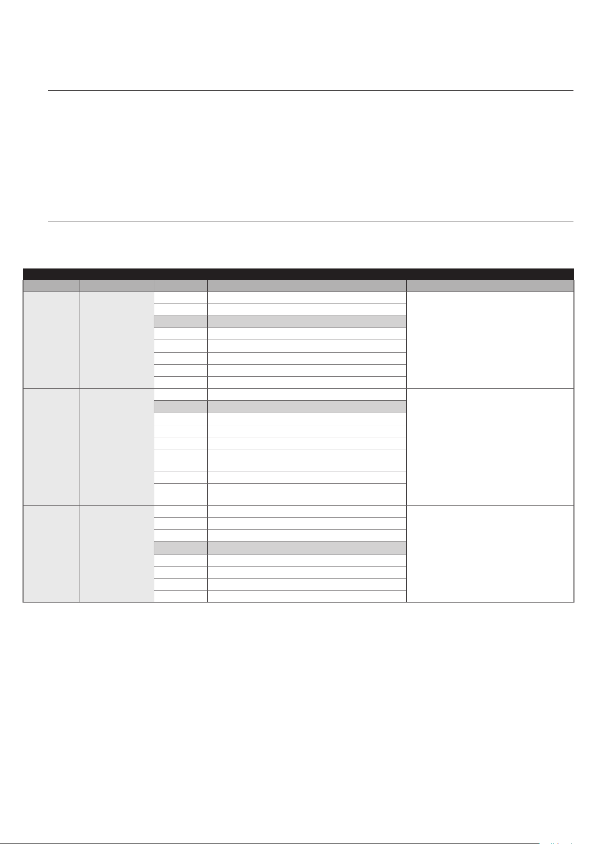
RECEIVER
7 PROGRAMMING
There are 3 buttons on the control unit: p, o and q (“Figure
23”) which can be used both to command the control unit during
the testing phase and to programme the available functions.
PROGRAMMING
23
FUSE
FUSE
LED
L1 ... L8
The available programmable functions are grouped into two levels
and their operating status is signalled by eight LEDs “L1 ... L8”
located on the control unit (LED lit = function enabled; LED off =
function disabled).
7.1 USING THE PROGRAMMING BUTTONS
The button allows for commanding the door opening move-
p
ment, or shifting the programming point upwards.
Button used to stop a manoeuvre
o
If pressed for more than 3 seconds, it allows for entering the
programming mode.
The button enables the user to close the door or shift the
q
programming point downwards.
During the manoeuvre, whether opening or closing is irrelevant, all the buttons perform the STOP function and stop the
motor’s movement.
16 – ENGLISH
Page 17

7.2 LEVEL 1 PROGRAMMING (ON-OFF)
All the Level 1 functions are factory-set to “OFF” and can be modied at any time. To check the various functions, refer to “Table 8”.
7.2.1 Level 1 programming procedure
The user has maximum 10 seconds to press the buttons consecutively during the programming procedure, af-
m
ter which time the procedure terminates automatically and memorises the changes made up to then.
To perform Level 1 programming:
1. press and hold the
2. release the
3. press the
4. press the
– short ash = OFF
– long ash = ON
5. wait 10 seconds (maximum time) to exit the programming mode.
To set other functions to “ON” or “OFF”, while the procedure is running, repeat points 2 and 3 during the phase
l
button when LED “L1” starts ashing
o
or q button to move the ashing LED to the LED associated with the function to be modied
p
button to change the status of the function:
o
itself.
LEVEL 1 FUNCTIONS (ON-OFF)
LED Function Description
L1 Automatic closing
L2 Close after photo
L3 Always Close
L4 Stand-by
L5 Long reversal
L6 Pre-ashing
L7 Sensitivity
L8 Type of door
button until LED “L1” starts ashing
o
Function ENABLED: after an opening manoeuvre there is a pause (equal to the set pause time), after which
the control unit automatically starts a closing manoeuvre. The pause time is set by default to 30 seconds.
Function NOT ENABLED: the system works in “semi-automatic” mode.
Function ENABLED: the behaviour changes depending on whether the “Automatic Closing” function is
enabled or not.
When “Automatic closing” is not active: The door always reaches the fully open position (even if Photo is
disengaged beforehand). When Photo disengages, automatic closing is triggered with a 5-second pause.
When “Automatic Closing” is enabled: the opening manoeuvre stops immediately after the photocells have
disengaged. After 5 seconds, the gate will start closing automatically.
The “Close After Photo” function is always disabled in manoeuvres interrupted by a Stop command.
Function DISABLED: the pause time is that which has been programmed or automatic re-closing will not take
place if the function is disabled.
Function ENABLED: in the event of a blackout, even of short duration, if the control unit detects that the door
is open once the electricity is restored, it automatically starts a closing manoeuvre, preceded by a 3-second
pre-ashing sequence.
Function DISABLED: when the electricity is restored, the gate remains in the same position.
Function ENABLED: 1 minute after the completion of the manoeuvre, the control unit switches off the
BlueBUS output (and, therefore, the devices) and all LEDs, with the exception of the BlueBUS LED, which
ashes more slowly. When the control unit receives a command, it restores full operation.
Function DISABLED: there will be no reduction in consumption.
This function is useful, in particular, during operation with the back-up battery.
Function ENABLED: once the STOP device or the force limiter intervenes, the movement is reversed up to the
maximum opening or closing position
Function DISABLED: the reversal is short (roughly 6in (15cm)).
Function ENABLED: a 3-second pause can be added between the switching on of the warning light and the
start of the manoeuvre, to warn the user in advance of a potentially dangerous situation.
Function DISABLED: the signalling of the warning light coincides with the start of the manoeuvre.
Function ENABLED: allows for considerably increasing the motor’s sensitivity in detecting obstacles. If used
to aid impact force detection, the “Speed” and “Motor force” parameters in the Level 2 menu must also be
adjusted.
Function DISABLED: the motor’s obstacle detection sensitivity is unchanged.
Function ENABLED: allows for selecting the type of door to be moved: Light or Heavy. If enabled, the control
unit is optimised to move Heavy doors.
Function DISABLED: the control unit is optimised to move smaller-size doors.
Table 8
During normal operation, in other words when no manoeuvre is under way, LEDs “L1 ... L8“” are on or off de-
l
pending on the status of the respective function; for example, “L1” is lit when the “Automatic Closing” function
is enabled. During the manoeuvre, LEDs “L1 ... L8” ash to signal the force required to move the door at that
time. If “L1” ashes, the force required is low and so forth, until LED “L8” ashes to signal the maximum force.
There is no relation between the force level indicated by the LEDs during the movement (which is an absolute
value) and the level indicated by the LEDs during the force (which is a relative value) programming phase. See
“L5” and “L6” in “Table 9”.
ENGLISH – 17
Page 18
7.3 LEVEL 2 PROGRAMMING (ADJUSTABLE PARAMETERS)
All the Level 2 parameters are factory-set as highlighted in “GREY” in “Table 9” and can be modied at any time. The parameters can
be set to a scale of 1 to 8. The check the value corresponding to each LED, refer to “Table 9”.
7.3.1 Level 2 programming procedure
The user has maximum 10 seconds to press the buttons consecutively during the programming procedure, af-
m
ter which time the procedure terminates automatically and memorises the changes made up to then.
To perform Level 2 programming:
1. press and hold the
2. release the
3. press the
4. press and hold the
– wait roughly 3 seconds, until the LED representing the current level of the parameter to be modied lights up
– press the
5. release the
6. wait 10 seconds (maximum time) to exit the programming mode.
To set multiple parameters during the procedure's execution, repeat the operations from point 2 to point 4 dur-
l
button when LED “L1” starts ashing
o
or q button to move the ashing LED to the “entry LED” associated with the parameter to be modied
p
p
button
o
ing the phase itself.
LEVEL 2 FUNCTIONS (ADJUSTABLE PARAMETERS)
Entry LED Parameter LED (level) Set value Description
L1* Pause Time
L2**
L3* Motor speed
Step-by-Step
function
button until LED “L1” starts ashing
o
button. With the o button pressed:
o
or q button to shift the LED associated with the parameter’s value
L1 10 seconds
L2 20 seconds
L3 40 seconds
L4 60 seconds
L5 80 seconds
L6 120 seconds
L7 160 seconds
L8 200 seconds
L1 Open - Stop - Close - Stop
L2 Open - Stop - Close - Open
L3 Open - Close - Open - Close
L4 Condominium
L5 Condominium 2 (more than 2 sec triggers “Stop”)
L6
L7 Hold-to-run
L8
L1 Speed 1 (30% - slow)
L2 Speed 2 (44%)
L3 Speed 3 (58%)
L4 Speed 4 (72%)
L5 Speed 5 (86%)
L6 Speed 6 (100% - fast)
L7 Open V4, close V2
L8 Open V6, close V4
Step-by-Step 2 (more than 2 sec triggers “Partial
Open”)
Opening in “semi-automatic” mode, closing in
“hold-to-run” mode
Table 9
Adjusts the pause time, in other words,
the time before automatic re-closure. It is
only effective if the “Automatic Closing”
function is enabled.
Controls the sequence of controls
associated with the Sbs input or the 1st
radio command.
Adjusts the motor speed during normal
manoeuvres.
18 – ENGLISH
Page 19

LEVEL 2 FUNCTIONS (ADJUSTABLE PARAMETERS)
Entry LED Parameter LED (level) Set value Description
L1 Door Open Indicator
L2 Enabled if door closed
L3 Enabled if door open
L4** FLASH output
L5*
L6*
L7*
L8
Motor force on
opening
Motor force on
closing
Maintenance
notice
List of
malfunctions
L4 Warning light
L5 Electric latch
L6 Electric lock
L7 Suction cup
L8 Maintenance indicator
L1 Force 1 (low)
L2 Force 2
L3 Force 3
L4 Force 4
L5 Force 5
L6 Force 6
L7 Force 7
L8 Force 8 (high)
L1 Force 1 (low)
L2 Force 2
L3 Force 3
L4 Force 4
L5 Force 5
L6 Force 6
L7 Force 7
L8 Force 8 (high)
L1
L2 1000
L3 2000
L4 4000
L5 6000
L6 8000
L7 10000
L8 12000
L1 Result of 1st manoeuvre (most recent)
L2 Result of 2nd manoeuvre
L3 Result of 3rd manoeuvre
L4 Result of 4th manoeuvre
L5 Result of 5th manoeuvre
L6 Result of 6th manoeuvre
L7 Result of 7th manoeuvre
L8 Result of 8th manoeuvre
Automatic (depending on the severity of the
manoeuvres)
Selects the device connected to the
FLASH output.
Adjusts the motor force control system to
adapt it to the weight of the door during
the opening manoeuvre.
Adjusts the motor force control system to
adapt it to the weight of the door during
the closing manoeuvre.
Adjusts the number of manoeuvres after
which the automation maintenance
request is triggered (see the “
“Maintenance notice” function”
paragraph).
Allows for viewing the type of anomalies
that occurred in the last 8 manoeuvres
(refer to the “Anomaly log” paragraph).
This is a read-only parameter, which
means that its values cannot be modied.
All parameters can be adjusted as desired without any problems; only the “Motor force on opening” and “Motor force on closing” settings
require special attention:
– high force values should not be used to compensate for points of abnormal friction on the leaf. Excessive force can jeopardise the
operation of the safety system or damage the leaf
– if the “Motor Force” control is used to aid the impact force reduction system, measure the force again after each adjustment in ac-
cordance with the EN 12445 standard
– wear and atmospheric conditions inuence the door’s movement, so the force settings should be checked periodically.
(*) If the value of a parameter falls between two adjacent values, the control unit will switch on intermittently the two LEDs identifying
the value itself. If necessary, the values can be rounded off by pressing the
or q button to round off respectively to the higher
p
or lower value among the two values highlighted by the control unit.
Example: Maintenance warning = 7000 manoeuvres - LEDs L5 and L6 ash. Pressing the
(6000), while pressing the
button rounds off to value L6 (8000).
p
button rounds off to value L5
q
If the value of a parameter is below the minimum value or above the maximum value among those listed in the table, the control
unit will switch on intermittently LED L1 or L8 respectively. If necessary, the values can be rounded off by pressing the
p
or q
button to round off to the nearest value.
Example: Pause Time = 5 seconds - LED L1 will ash. Pressing the
button rounds off to value L1 (10 s) and L1 will no longer
p
ash because the parameter will have been rounded off to a known value.
(**) If the conguration has not been learned, when LEVEL 2 of the MENU opens up, the control unit will propose the default cong-
uration.
ENGLISH – 19
Page 20

7.4 PROGRAMMING THE DIRECTION
This procedure allows for reversing the motor’s rotation direction.
To do this:
1. press and hold the
2. release the
3. simultaneously press the
motor’s direction
4. release the
– the lit courtesy light signals that the reversal of the motor
direction has been programmed
– if the courtesy light is off, the standard motor rotation di-
rection has been programmed.
5. wait 10 seconds to exit the programming mode due to the
expiry of the maximum time limit.
Note Points 3 and 4 can be repeated during the same program-
ming phase to change the direction of motor rotation.
When the direction of motor rotation is changed,
m
button when LED “L1” starts ashing
o
and q buttons:
p
button for roughly 3 seconds
o
and q buttons to change the
p
the “Position memorisation” procedure must be repeated (refer to the “Learning of the door opening
and closing positions” paragraph).
At the end of the programming procedure, it is necessary to verify
the direction of motor rotation.
To do this:
1. disconnect the power supply (by removing the plug or fuse)
2. power the device
3. after the initial ashing of LEDs “L1 … L8”, a single LED light
up to signal the encoder position
4. on the signal indicating the encoder position, check the
courtesy light:
– if the courtesy light switches on, the reversed direction of
motor rotation has been programmed
– if the courtesy light is off, the standard motor rotation di-
rection has been programmed.
7.5 RESETTING THE ENCODER POSITION
This procedure allows for restoring the encoder to the factory-set
position to enable the assembly of Soon with the door closed. At
the same time, it will reset the factory settings in the memory: all the
parameters and the settings chosen by the user will be restored.
If the motor’s direction of rotation must be modied, rst run the
“Programming the direction” procedure then the “Resetting
the encoder position” procedure.
The procedure described below must be performed
m
exclusively on a workbench. Do not perform the
procedure with the motor installed.
To do this:
1. press and hold the
“L1” to “L8” light up.
2. release the buttons when only one lights up again (from “L1”
to “L8”) to signal the current position of the encoder
3. press and release the
The control unit commands the motor’s movement to bring
the encoder position to LED “L7”
4. once the motor has stopped, all LEDs switch on and then
off; at this point, check that the LED that lights up again is
“L7”. If this does not occur, repeat the procedure
5. at the end of the sequence, LEDs “L1” and “L2” continue
to ash.
and q buttons until all LEDs from
p
button when the motor restarts.
o
7.6 SPECIAL FUNCTIONS
7.6.1 “Always open” function
The “Always open” function is a control unit feature that enables the
user to always command an opening manoeuvre when the “Step-
by-Step” command lasts longer than 2 seconds; this is useful,
for example, for connecting a timer contact to the SbS terminal in
order to keep the gate open for a certain time frame.
This feature is valid regardless of how the “SbS” input is programmed, unless it is programmed to perform the “Condominium 2” function. Refer to the “Step-by-Step function” under the “
Level 2 programming (adjustable parameters)” paragraph.
7.6.2 “Move anyway” function
This function can be used to operate the automation even one or
more some safety devices fail to work properly or are out of order.
The automation can be controlled in “hold-to-run” mode by proceeding as follows:
1. send a command to operate the gate, using a transmitter or
key selector, etc. If everything functions properly, the gate
will move normally, otherwise proceed with point 2
2. within 3 seconds, press the control again and hold it down
3. after roughly 2 seconds, the gate will complete the request-
ed manoeuvre in “hold-to-run” mode, in other words, it will
continue to move so long as the control is held down.
When the safety devices fail to work, the warning
l
light will emit a few ashes to signal the type of
problem. To verify the type of anomaly, consult the “
TROUBLESHOOTING GUIDE” chapter.
7.6.3 “Maintenance notice” function
This function noties the user when the automation needs a maintenance check. The number of manoeuvres after which the signal
is triggered can be selected among 8 levels, through the “Main-
tenance notice” adjustable parameter (see paragraph “Level 2
programming (adjustable parameters)“).
Level 1 adjustment is “automatic” and takes into account the severity of the manoeuvres, in other words, their force and duration,
while the other adjustments are dened on the basis of the number
of manoeuvres.
The maintenance signal is sent through the Flash warning light or
the maintenance indicator, depending on the relative settings (see
paragraph “Level 2 programming (adjustable parameters)“).
The “Flash” warning light and the maintenance indi-
l
cator give the signals indicated in “Table 10” based
on the number of manoeuvres completed with respect to the set limit.
20 – ENGLISH
Page 21

Table 10
RECEIVER
RECEIVER
RECEIVER
MAINTENANCE NOTICE THROUGH FLASH AND MAINTENANCE
INDICATOR
Number of
manoeuvres
Below 80% of the
limit
Between 81% and
100% of the limit
Exceeding 100% of
the limit
Signal on “Flash”
Normal (0.5 sec on,
0.5 sec off)
Remains lit for 2
seconds at the start
of the manoeuvre
Remains lit for 2
seconds at the
start and end of the
manoeuvre then
carries on normally
Maintenance
indicator signal
Lit for 2 seconds
at the start of the
opening manoeuvre
Flashes for the
entire duration of the
manoeuvre
Flashes always
7.7 VERIFYING THE NUMBER OF MANOEUVRES COMPLETED
The “Maintenance notice” function can be used to verify the
number of manoeuvres completed as a percentage of the set limit.
24
L7
FUSE
LED
FUSE
25
L7
FUSE
LED
L1
To do this:
1. press and hold the
2. release the
3. press the
that is, the “entry LED” for the “Maintenance notice” parameter
4. press and hold the
– wait roughly 3 seconds until the LED representing the cur-
rent level of the “Maintenance notice” parameter lights
up
– press and hold for at least 5 seconds the
tons then release them. The LED corresponding to the
selected level will emit a series of fast ashes to signal that
the manoeuvre counter has been reset
5. release the
button when LED “L1” starts ashing
o
or q button to shift the ashing LED to “L7”,
p
button
o
button until LED “L1” starts ashing
o
button. With the o button pressed:
o
FUSE
p
7.9 MEMORY DELETION
and q but-
L1
To do this:
1. press and hold the
2. release the
3. press the
that is, the “entry LED” for the “Maintenance notice” parameter
4. press and hold the
– wait roughly 3 seconds until the LED representing the cur-
rent level of the “Maintenance notice” parameter lights
up
– press and immediately release the
– the LED corresponding to the selected level will ash a
few times; the number of ashes indicates the percentage
of manoeuvres performed (in multiples of 10%) with re-
spect to the set limit. For example: with the maintenance
notice set to L7 namely 10000, 10% corresponds to 1000
manoeuvres; if the visualisation LED ashes 4 times, it
means that 40% of the manoeuvres has been reached
(being between 4000 and 4999 manoeuvres). If 10% of
the manoeuvres has not yet been reached, the LED does
not ash at all.
5. release the
button when LED “L1” starts ashing
o
or q button to shift the ashing LED to “L7”,
p
button.
o
button until LED “L1” starts ashing
o
button. With the o button pressed:
o
and q buttons
p
7.8 MANOEUVRE COUNTER RESETTING
Once maintenance has been performed on the system, the manoeuvre counter must be reset.
The procedure described below restores the con-
m
trol unit’s default settings. All the custom settings
will be lost.
26
FUSE
FUSE
LED
L1 ... L8
To delete the control unit’s memory and restore all the default settings, proceed as described below:
1. press and hold the
LEDs “L1-L8” light up (after roughly 3 seconds)
2. release the buttons
3. if the operation was successful, the programming LEDs “L2”
and “L8” will ash rapidly for 3 seconds.
With this procedure it is possible to also delete any
l
errors left in the memory.
This procedure does not cancel the parameter rel-
l
ative to the motor’s rotation direction and the num-
ber of manoeuvres executed.
and q buttons until the programming
p
ENGLISH – 21
Page 22

8
8 TROUBLESHOOTING GUIDE
8.1 TROUBLESHOOTING
The table below contains useful instructions to resolve any malfunctions or errors that may occur during installation or in case of a fault.
TROUBLESHOOTING
Problems Recommended checks
The radio transmitter does not control the
automation and the LED on the transmitter
fails to light up
The radio transmitter does not control the
automation but the LED on the transmitter
lights up
No manoeuvre starts and the “BlueBUS”
LED does not ash
No manoeuvre starts and the warning light
is off
No manoeuvre starts and the warning light
ashes a few times
The manoeuvre starts but is immediately
followed by a reverse run
The manoeuvre is completed correctly but
the warning light does not work
LED “L1” or LED “L8” ashes rapidly
(troubleshooting guide)
Table 11
Check whether the transmitter batteries are exhausted and replace them if necessary.
Check whether the transmitter has been memorised correctly in the radio receiver.
Check that the gearmotor is being powered with the mains voltage
Check whether fuses F1 and F2 are blown; if they are, identify the cause of the failure
then replace the fuses with others having the same current rating and characteristics.
Check that the command is actually received. If the command reaches the Step-by-Step
input, the corresponding “SbS” LED must light up; if instead the radio transmitter is used,
the “BlueBUS” LED must emit two quick ashes.
Count the number of ashes and check the corresponding value in “Table 13”.
The selected force value may be too low to move the type of gate. Check whether there
are any obstacles and, if necessary, select a higher force.
Check whether a safety device connected to the Stop input has tripped.
Make sure that there is voltage on the warning light’s FLASH terminal during the
manoeuvre (being intermittent, the voltage value is not signicant: roughly 10–30 Vc); if
there is voltage, the problem is due to the lamp, which must be replaced with one having
the same characteristics; if there is no voltage, there may have been an overload on the
FLASH output. Check that the cable has not short-circuited.
This means that the high overrun position (LED “L1” ashes rapidly) or the low overrun
position (LED “L8” ashes rapidly) has been reached.
If LED “L1” ashes, perform a closing manoeuvre until LED “L1” stops ashing rapidly.
Then detach Soon from the spring support shaft, open the door to the maximum position
and re-install Soon from this position.
If LED “L8” ashes, perform an opening manoeuvre until LED “L8” stops ashing
rapidly. Then detach Soon from the spring support shaft, close the door to the maximum
position and re-install Soon from this position.
TROUBLESHOOTING...
27
F2
2
1
F1
Table 12
CHARACTERISTICS OF FUSES F1 AND F2
F1 Mains Power Supply Fuse = 1.6A
F2 Control Unit Fuse = 1.6 Delayed
Fuse F1 can be accessed after removing screw (1) and cover (2).
22 – ENGLISH
Page 23
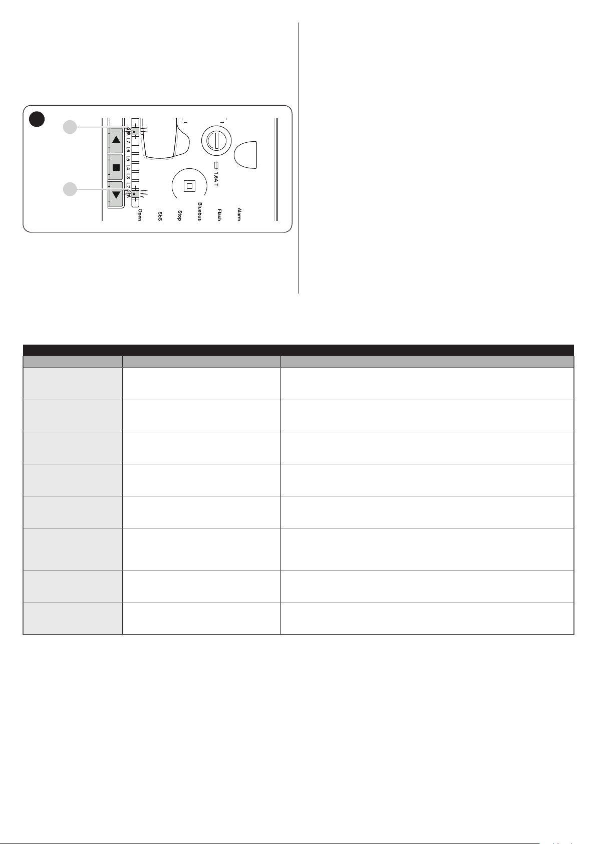
8.2 ANOMALY LOG
RECEIVER
The gearmotor allows for displaying any anomalies that occurred in
the last 8 manoeuvres, for example, the interruption of a manoeuvre due to the intervention of a photocell or sensitive edge.
To do this:
1. press and hold the
2. release the
button when LED “L1” starts ashing
o
button until LED “L1” starts ashing
o
28
L8
FUSE
LED
L1
FUSE
3. press the p or q button to shift the ashing LED to “L8”,
that is, the “entry LED” for the “List of anomalies” parameter
4. press and hold the
button. With the o button pressed:
o
5. wait roughly 3 seconds, after which the LEDs corresponding
to the manoeuvres that had anomalies will light up. LED L1
indicates the result of the most recent manoeuvre, while LED
L8 indicates the result of the eighth manoeuvre. If the LED
is lit, it means that anomalies occurred during the manoeuvre; if the LED is off, the manoeuvre terminated without any
anomalies
6. press the
or q button to select the desired manoeuvre:
p
the corresponding LED will ash the same number of times
as those emitted by the warning light following an anomaly
(see “Table 13”)
7. release the
button.
o
8.3 SIGNALLING THROUGH WARNING LIGHT
During the manoeuvre, the “FLASH” warning light ashes once every second; whenever anomalies occur, shorter ashes are emitted; the
ashes are repeated twice with a one-second pause in between.
Table 13
FLASH WARNING LIGHT SIGNALS
Fast ashes Cause ACTION
2 ashes
1-second pause
2 ashes
3 ashes
1-second pause
3 ashes
4 ashes
1-second pause
4 ashes
5 ashes
1-second pause
5 ashes
6 ashes
1-second pause
6 ashes
7 ashes
1-second pause
7 ashes
8 ashes
1-second pause
8 ashes
9 ashes
1-second pause
9 ashes
Intervention of a photocell
Intervention of the “Motor Force” limiter
Intervention of the STOP input
Error in the internal parameters of the
control unit
The maximum number of manoeuvres
per hour limit has been exceeded
Error in the internal electric circuits
A command that prevents other
commands from being executed is
already present
The automation was stopped by a
“Stop automation” command
At the start of the manoeuvre, one or more photocells are blocking
the movement; check whether there are any obstacles. During the
manoeuvre, this is normal if an obstacle is present.
During the movement, the door experienced excessive friction; identify the
cause.
At the start of the manoeuvre or during the movement, the STOP input
intervened; identify the cause.
Wait at least 30 seconds then try giving a command; if the condition
persists, it means that there is a serious malfunction and the electronic
board must be replaced.
Wait a few minutes until the manoeuvre limiter drops below the maximum
limit.
Disconnect all the power circuits for a few seconds and then try giving a
command again; if the condition persists, it means there is a serious fault
on the electronic board or on the motor cabling. Perform any necessary
checks and replacements.
Another command is already present. Remove the command present to
be able to send other commands.
Unlock the automation mechanism by giving the “Unlock automation”
command.
ENGLISH – 23
Page 24

8.4 SIGNALS ON THE CONTROL UNIT
AB
The control unit has a series of LEDs, each of which can emit special signals both during regular operation and when an anomaly
29
D
LED
occurs.
A BlueBus LED
B Light Led, Open, Sbs, Stop
C “L1 ... L8” programming LEDs
C
Light
D Courtesy light
TERMINAL LEDS ON THE CONTROL UNIT
Status Meaning Possible solution
BlueBus LED
Check for the presence of power; check that the fuses are not blown;
OFF Anomaly
if necessary, identify the cause of the fault then replace them with fuses
having the same specications.
There is a serious anomaly; try switching off the control unit for a few
On Serious anomaly
seconds; if the condition persists, it means that there is a fault and the
electronic circuit board must be replaced.
1 green ash per second Everything normal Normal control unit operation.
This is normal when there is a change in one of the inputs: SbS, STOP,
2 quick green ashes The status of the inputs has changed
OPEN, LIGHT, the photocells intervene or a command has been given
to the control unit.
A series of ashes
separated by a 1-second
Various Refer to that shown in “Table 13”.
pause
A series of quick and
extended red ashes
Short circuit on the BlueBUS terminal
clamp
Disconnect the terminal and verify the cause of the short-circuit on the
BlueBUS connections. If the short-circuit is resolved, the LED will start
ashing normally after about ten seconds.
STOP LED
OFF Intervention of the STOP input Check the devices connected to the STOP input.
On Everything normal STOP input active.
SbS LED
OFF Everything normal SbS input not active.
On Intervention of the SbS input
This is normal if the device connected to the SbS input is actually
active.
OPEN LED
OFF Everything normal OPEN input not active.
On Intervention of the OPEN input
This is normal if the device connected to the OPEN input is actually
active
LIGHT Led
OFF Everything normal LIGHT input not active.
On Intervention of the LIGHT input
This is normal if the device connected to the LIGHT input is actually
active.
FUSE
Flash Alarm
Bluebus
StopSbSOpenLight
Table 14
CONTROL UNIT COURTESY LIGHT
Status Description
OFF Automation Stopped
Steady Lit Manoeuvre in progress
On 3 sec Automation Lock Command Executed
The control unit must run the automatic force search procedure (refer to the “Learning of the door opening and
Flashes
closing positions” paragraph). If the courtesy light ashes also during the manoeuvre, it means that a procedure is
under way to detect the critical points of the manoeuvre.
If it ashes synchronously with the warning light, there is an anomaly (refer to “Table 13”).
24 – ENGLISH
Table 15
Page 25

LEDS ON THE CONTROL UNIT BUTTONS
LED 1 Description
OFF During normal operation, this indicates that “Automatic Closing” is disabled.
On During normal operation, this indicates that “Automatic Closing” is active.
Function programming in progress.
With the motor stationary, if it ashes individually it means that the encoder position is in the Low Overrun position
Flashes
(position below or equal to 5%). Adjust the position then rerun the position search procedure.
If it ashes together with “L2”, it means that the device learning phase must be carried out (refer to the “Device
learning” paragraph).
LED 2 Description
OFF During normal operation, it signals that the “Close after photo” mode is not active.
On During normal operation, it signals that the “Close after photo” mode is active.
Function programming in progress.
Flashes
If it ashes together with “L1”, it means that the device learning phase must be carried out (see the “Device learning”
paragraph)
LED 3 Description
OFF During normal operation, this indicates that “Always Close” is not active.
On During normal operation, it signals that “Always close” is active.
Function programming in progress.
Flashes
If it ashes together with L4, it means that the door opening and closing positions must be learned (refer to the “
Learning of the door opening and closing positions” paragraph).
LED 4 Description
OFF During normal operation, it signals that the “Stand-by” mode is not active.
On During normal operation, it signals that the “Stand-by” mode is active.
Function programming in progress.
Flashes
If it ashes together with L3, it means that the door opening and closing positions must be learned (refer to the “
Learning of the door opening and closing positions” paragraph).
LED 5 Description
OFF During normal operation, it indicates that “Long reversal” is not enabled.
On During normal operation, it indicates that “Long reversal” is enabled.
Flashes Function programming in progress.
LED 6 Description
OFF During normal operation, it signals that the “Pre-ashing” mode is not active.
On During normal operation, it signals that the “Pre-ashing” mode is active.
Flashes Function programming in progress.
LED 7 Description
OFF During normal operation, it indicates that “Sensitivity” is not enabled.
On During normal operation, it indicates that “Sensitivity” is enabled.
Flashes Function programming in progress.
LED 8 Description
OFF During normal operation, it indicates that the installation includes 1 motor.
On During normal operation, it indicates that the installation includes 2 motors.
Function programming in progress.
Flashes
With the motor stationary, if it ashes individually it means that the encoder position is in the High Overrun position
(position above or equal to 95%). Adjust the position then rerun the position search procedure.
Table 16
ENGLISH – 25
Page 26

9
9 FURTHER DETAILS (Accessories)
9.1 MODIFYING THE STOP INPUT
STOP is the input that causes immediate stoppage of the manoeuvre followed by its brief reversal. Devices with output featuring normally open “NO” and normally closed “NC” contacts, as well as
devices with 8.2 kΩ xed resistor output, such as sensitive edges,
can be connected to this input.
As with the BlueBUS, the control unit recognises the type of device
connected to the STOP input during the learning phase (see the “
Device learning” paragraph); subsequently the control unit gives
a STOP command when it detects a variation with respect to the
learned status.
Multiple devices, even of different types, can be connected to the
STOP input if suitable arrangements are made:
– Any number of NO devices can be connected to each other in
parallel.
– Any number of NC devices can be connected to each other in
series.
– Two devices with 8.2 kΩ xed resistor output can be connected
in parallel; if there are more than 2 devices then they must all be
connected in cascade, with a single 8.2 kΩ terminating resistor.
– It is possible to combine two NO and NC contacts by placing
them in parallel, while also mounting a 8.2 kΩ resistor in series
with the NC contact (this also allows for combining 3 devices:
NA, NC and 8.2 kΩ).
(Accessories)
CONFIGURATION
FURTHER INFORMATION
If required, the alarm siren can be disconnected and the ALARM
output can be recongured for other applications: in this case the
alarm will be disabled, but all the other safety systems required to
detect obstacles will remain active.
The alarm system can be activated/deactivated using the Oview
programmer (see paragraph “Connecting the Oview program-
mer“).
9.3 CONNECTING AN SM-TYPE RADIO RECEIVER
The control unit has a slot for mounting radio receivers with SM
connector (optional accessories) belonging to the SMXI, SMXIS,
OXI, etc. families, which can be used to remotely control the control unit through transmitters that intervene on the control unit’s
inputs.
Before installing a receiver, disconnect the power
f
supply to the control unit.
To install a receiver ("Figure 30"):
1. insert the receiver (A) in the appropriate slot (B) on the control unit’s electronic board.
30
B
A
If the STOP input is used to connect devices with
a
safety functions, only those devices with 8.2 kΩ
xed resistor guarantee Category 3 safety against
faults in accordance with the EN 13849-1 standard.
9.2 ALARM SYSTEM
Congured control units, and those identied with code ***/V1,
have an integrated alarm system that activates following 2 consecutive obstacle detections, or sensitive edge interventions, during
the manoeuvre.
The moment the automation reaches the closed position, the alarm
system resets and prepares for subsequent manoeuvres.
After two interventions as described above, the control unit inhibits any movement by activating the automation’s permanent lock
and triggering the siren (connected to the ALARM terminal) for 5
minutes.
To unlock the automation and silence the siren, (any) one of the
following must occur: the STOP button on the control panel is
pressed, the sensitive edge is pressed, the contact on the SbS
terminal is triggered (with the motor stopped) or the contact on the
STOP terminal (NC) is triggered. From then onwards, the control
unit will resume its normal operation.
The start of each closing manoeuvre (commanded from a radio
transmitter or Oview Terminal) is preceded by a pre-ashing sequence and by the activation of the siren for 5 seconds (non-ex-
cludable), after which the motor will start.
If the aerial incorporated in LUCYB or other type
l
of external aerial is not used, screw the rigid cable
supplied with the receiver onto the aerial terminal
(“Figure 31”):
31
In the event of a power supply failure during the
l
automation’s permanent lock condition, the alarm
system will re-emit the acoustic and visual signals
for 5 minutes at the next re-start of the control unit.
The alarm system is active by default and can be
a
deactivated by the user: please note, however, that
in this case the control unit will no longer be compliant with standard UL325.
26 – ENGLISH
The association between the radio receiver output and the com-
mand executed by the motor is shown in “Table 17”:
Page 27

Table 17
A
SMXI / SMXIS
Receiver output Command
Output No. 1 “Step-by-Step”
Output No. 2 “Partial opening”
Output No. 3 “Open”
Output No. 4 “Close”
If the OXI radio receiver used in “EXTENDED MODE” is installed, it
may send the commands shown in “Table 18“.
Table 18
OXI / OXIFM /OXIT / OXITFM IN MODE 2 EXTENDED
No. Command Description
1 Step-by-Step “SbS” (Step-by-Step) command
2 Partial opening 1 “Partial opening 1” command
3 Open “Open” command
4 Close “Close” command
5 Stop Stops the manoeuvre
Condominium
6
Step-by-Step
High priority Step-
7
by-Step
8 Partial open 2
9 Partial open 3
Opens and locks
10
the automation
Closes and locks
11
the automation
12 Lock automation
Release
13
automation
On Timer
14
Courtesy light
On-Off
15
Courtesy light
Command in condominium mode
Commands also with the automation
locked or the commands enabled
Partial opening (the M2 gate leaf
opens to 1/2 the full length)
Partial open (the two gate leaves open
to 1/2 the full length)
Triggers an opening manoeuvre
and, once this terminates, locks the
automation; the control unit will not
accept any command other than “High
priority Step-by-Step” and automation
“Unlock”, or (only from Oview) the
following commands: “Unlock and
close” and “Unlock and open”
Triggers a closing manoeuvre and,
once this terminates, locks the
automation; the control unit will not
accept any command other than “High
priority Step-by-Step” and automation
“Unlock”, or (only from Oview) the
following commands: “Unlock and
close” and “Unlock and open”
Triggers the stoppage of the
manoeuvre and locks the automation;
the control unit will not accept any
command other than “High priority
Step-by-Step” and automation
“Unlock”, or (only from Oview) the
following commands: “Unlock and
close” and “Unlock and open”
Triggers unlocking of the automation
and restores normal operation
The courtesy light output switches on
with timer-based switching off
The courtesy light output switches on
and off in Step-by-step mode
9.4 CONNECTING AND INSTALLING THE BACKUP BATTERY
The electrical connection of the battery to the con-
f
trol unit must be made only after completing all the
installation and programming stages, as the battery
is an emergency power supply.
To install and connect the battery:
1. remove the plastic protection (A) with the aid of a screwdriver
32
2. connect the appropriate cable to the back-up battery con-
nector
33
3. insert the relative connector (C) on the control unit
34
For further information, consult the specic manual
l
of the receiver.
C
ENGLISH – 27
Page 28

4. insert the back-up battery (B) into its housing inside the mo-
tor body.
35
C
B
9.5 CONNECTING THE OVIEW PROGRAMMER
The control unit has a BusT4 connector to which the “Oview”
programmer can be connected, through the IBT4N interface. The
programmer allows for fully and rapidly managing the installation,
maintenance and diagnosis of the entire automation.
To access the connector, proceed as shown in the gure and connect the connector to its relevant slot.
36
The Oview can be connected to multiple control units simultaneously (up to 16 without any particular precautions) and can be left
connected to the control unit during the automation’s normal operation. In this case, it can be used to send commands directly to the
control unit using the specic “user” menu.
It is also possible to update the rmware. If the control unit has a
radio receiver belonging to the OXI family, the “Oview” can be used
to access the transmitter parameters memorised in the receiver.
For more detailed information, consult the respective instruction
manual and the “Opera system book” manual.
28 – ENGLISH
Page 29

9.6 CONNECTING THE SOLEMYO SOLAR ENERGY SYSTEM
A
When the automation is powered by the “Solemyo” system, IT MUST NOT BE POWERED by the electricity grid
f
at the same time.
For information on the “Solemyo” system, consult the relevant instruction manual.
l
To connect the “Solemyo” system:
1. remove the plastic protection (A) with the aid of a screwdriver
2. insert the relative connector (B) on the control unit.
37
B
ENGLISH – 29
Page 30

10
10 PRODUCT MAINTENANCE
The automation must be subjected to regular maintenance to keep
its safety level constant and guarantee long-lasting operation; to
this aim, Soon has a manoeuvre counter and maintenance warning system; refer to the ““Maintenance notice” function” paragraph.
a
To carry out maintenance on the gearmotor:
1. Schedule maintenance interventions within maximum 6
2. disconnect all power supplies, including any back-up bat-
3. check for any deterioration in the materials making up the
4. check the state of wear of moving parts: pinion, rack and all
5. connect the power supplies again and run all the tests and
PRODUCT MAINTENANCE
Maintenance must be carried out strictly in compliance with the safety provisions provided in this
manual and in accordance with the laws and regulations in force.
months or after maximum 4.000 manoeuvres from the previous maintenance intervention
teries
automation, with special emphasis on erosion or oxidation of
the structural parts; replace any parts that are not to standard
gate leaf components; replace any worn parts
checks described in the “Testing” paragraph.
11
11 PRODUCT DISPOSAL
l
As with the installation, only qualied personnel must dismantle the
product at the end of its life.
This product is composed of different types of materials. Some
of these materials can be recycled; others must be disposed of.
Please enquire about the recycling or disposal systems in place in
your local area for this type of product.
a
l
PRODUCT DISPOSAL
This product is an integral part of the operator and
must therefore be disposed of with it.
WARNING
Some parts of the product may contain polluting or
dangerous substances. If not disposed of correctly,
these substances may have a damaging effect on
the environment and human health.
As indicated by the symbol shown
here, this product must not been
disposed of with household
waste. Separate the waste for disposal and recycling, following the
methods stipulated by local regulations, or return the product to
the seller when purchasing a new
product.
WARNING
a
Local regulations may impose heavy penalties if
this product is not disposed of in compliance with
the law.
30 – ENGLISH
Page 31

12
12 TECHNICAL SPECIFICATIONS
l
TECHNICAL SPECIFICATIONS
All technical specications stated in this section refer to an ambient temperature of 20°C (± 5°C). Nice S.p.A.
reserves the right to apply modications to the product at any time when deemed necessary, without altering
its functions and intended use.
Table 19
TECHNICAL SPECIFICATIONS
Description Technical specication
Product type Electromechanical gearmotor for sectional doors
Power supply
Maximum current draw (A) 3,0
Nominal current draw (A) 2
Maximum torque (Nm) 50
Rated torque (Nm) 30
Maximum power consumption (W) 350
Nominal power consumption (W) 220
Maximum speed (rpm) 30
Nominal speed (rpm) 18
Static holding torque (Nm) 130
Protection rating (IP) 40
Operating temperature (min/max °C) -20°C ÷ 50°C
Maximum door surface area 215ft2 40in2 1/16 (20 mq)
Maximum door height 16ft 4in 55/64 (5 m)
Insulation class I
Durability
Cycles per hour at the rated torque – for doors with 3 m
height (cycles/hour)
Dimensions 4in 1/2 x 14in 3/4 x 11in 13/16 (115x375x300 mm)
Weight 23 lb (10,5 Kg)
Hole 1in (25,5 mm)
Emergency power supply Yes (PS124 battery)
Courtesy light Integrated with LED
Warning light output [Note 1] For 1 LUCYB warning light; MLB or MLBT (12 V, 21 W lamp)
ALARM output [Note 1] for 24Vdc 108dB Siren
BLUEBUS output One output with maximum load of 12 BlueBUS units
STOP input
Sbs input [Note 2]
OPEN input [Note 2]
LIGHT input [Note 2]
Radio ANTENNA input 52 Ω for RG58-type cable or similar
Programming input For 1 OVIEW programmer with 4-pin telephone cable and RJ14 connector
Radio connector SM connector for SMXI, SMXIS or OXI receivers
Programmable functions 8 ON-OFF and 8 adjustable functions
Self-learning functions
Use in highly acid, saline or potentially explosive
atmosphere
120Va (+10% -15%) 60Hz
Estimated between 40,000 and 120,000 cycles, depending on the
conditions specied in the “Product durability” paragraph
15
For normally closed or normally open contacts or for 8.2 kΩ xed resistor
contacts with self-learning (any variation from the memorised status
triggers the STOP command, and with the alarm system triggered, allows
the automation to be released)
For normally open contacts (the closing of the contact triggers the STEPBY-STEP command, and with the motor stopped and the alarm system
triggered, allows the automation to be released)
For normally open contacts (closing of the contact triggers the “OPEN”
command)
For normally open contacts (the closing of the contact causes the
Courtesy Light status to switch)
Self-learning of the devices connected to the BlueBus output
Self-learning of the type of “STOP” device (Normally Open, Normally
Closed contact or 8.2 kΩ resistor)
No
Note 1 The output can be programmed with other functions (see “Table 9” or through the Oview programmer).
Note 2 The inputs can be programmed with other functions through the Oview programmer.
ENGLISH – 31
Page 32

NOTES
32 – ENGLISH
Page 33

&
INSTRUCTIONS AND WARNINGS FOR THE USER
Before using the automation for the rst time, ask the installer to
explain the origin of any residual risks and take a few minutes to
read this instruction manual and warnings for the user given to you
by the installer. Store the manual for future reference and hand it to
the new owner when transferring the automation.
WARNING!
a
Your automation is a machine that faithfully executes commands imparted by the user. Negligence
and improper use may lead to dangerous situations:
– do not manoeuvre the gate if there are people, animals or
objects within its range of operation
– it is strictly forbidden to touch parts of the automation
while it is moving
– the photocells are not a safety device but only an auxiliary
aid to safety. They are built using highly reliable technol-
ogy but, in extreme conditions, may malfunction or even
become defective. In certain cases, the defect may not
be clearly evident. For these reasons, it is important to
follow all the instructions given in this manual when using
the automation
– periodically check that the photocells work properly.
IT IS STRICTLY FORBIDDEN to transit while the au-
a
tomation is closing! Transit is allowed only if the automation is fully open and stationary.
CHILDREN
a
An automation system guarantees a high degree
of safety. With its detection systems, it can control
and guarantee the gate’s movement in the presence
of people or objects. It is nonetheless advisable to
forbid children from playing near the automation
and not to leave remote controls near them to prevent any unwanted activation of the system. The
automation is not a toy!
The product is not intended for use by persons, including children, with limited physical, sensory or
mental capacities, or who lack experience or knowledge, unless supervised or trained in the use of the
product by a person responsible for their safety.
Anomalies: if the automation shows any signs of anomalous be-
haviour, disconnect the power supply to the system and manually
unlock the motor (see instructions at the end of the chapter) to
manoeuvre the automation manually. Do not attempt any repairs
personally, but contact your trusted installer.
Do not modify the system or the programming and
l
adjustment parameters of the control unit: your installer is exclusively responsible for these operations.
Failure or lack of power supply: while waiting for the installer
to intervene or the electricity to be restored, if the system is not
equipped with back-up batteries, the automation can nonetheless
be used by manually unlocking the motor (see the instructions at
the end of the chapter) and moving the automation manually.
Safety devices out of order: the automation can also be used
when one or more safety devices are defective or out of order.
The automation can be controlled in “Hold-to-run” mode in the
following way:
1. send a command to operate the gate using a transmitter or
key selector, etc. If everything works normally, the automa-
tion will move regularly, otherwise the warning light will ash
a few times and the manoeuvre will not start (the number
of ashes depends on the reason for which the manoeuvre
cannot start)
2. in this case, within 3 seconds press the control again and
hold it down
3. after roughly 2 seconds, the automation will complete the requested manoeuvre in “Hold-to-run” mode, in other words,
it will continue to move so long as the control is held down.
If the safety devices are out of order, have the sys-
m
tem repaired as soon as possible by a qualied
technician.
The test, periodic maintenance and any repairs must be documented by the person carrying out the work and the documents must
be stored by the owner of the automation. The only interventions
the user may carry out periodically include cleaning of the photocell
glass components (use a soft and slightly damp cloth) and removing any leaves or stones that may obstruct the automation.
Before carrying out any maintenance operations,
m
the user of the automation must manually unlock
the motor to prevent anyone from accidentally triggering the automation’s movement (see the instructions at the end of the chapter).
Maintenance: in order to ensure constant levels of safety and the
longest useful life for the automation, routine maintenance must be
carried out (at least every 6 months).
Only qualied personnel is authorised to carry out
l
checks, maintenance operations and repairs.
Disposal: at the end of its useful life, the automation must be dis-
mantled by qualied personnel and the materials must be recycled
or disposed of in compliance with the local regulations in force.
Replacing the remote control battery: if your remote control
appears to be working poorly after some time, or stops working
altogether, it may simply depend on at batteries (depending on
how much the device is used, the batteries may last from several
months to over a year). You will notice this by the fact that the
indicator light signalling the transmission fails to light up, is weak
or lights up only for a short time. Before contacting the installer, try
replacing the battery with that of another transmitter that works
properly: if the anomaly is resolved, simply replace the at battery
with one of the same type.
&
ENGLISH – 33
Page 34

Unlocking and manual movement
The gate can only be unlocked once the leaf has
a
come to a standstill.
The gearmotor is equipped with a mechanical unlocking device
that can be used to open and close the door manually.
These manual operations should only be performed in case of a
power outage, malfunctions or during the installation phases.
To unlock the device:
1. pull the ball (A)
2. the door can now be moved manually to the desired posi-
tion.
38
&
A
To lock the mechanism, pull the ball (B).
B
34 – ENGLISH
&
Page 35

NOTES
ENGLISH – 35
Page 36

Nice SpA
Via Callalta, 1
31046 Oderzo TV Italy
info@niceforyou.com
IDV0697A00EN_14-06-2019
www.niceforyou.com
 Loading...