

– 1 –
Signo
Automatic barrier
New integrated operations to the Signo
barrier operator
Warning! – The present instructions must be integrated to those in the
instructions manual of the automation system.
This addendum presents the new functions that have been recently
integrated to all SIGNO series barrier operator models. Below are the
functions that have been recently introduced:
• New universal control unit, mod. SIA20/A.
• Possibility of synchronising the operations of two Signo
together (Master & Slave operations).
• New procedure for the personalisation of the bar’s “movement deceleration”.
• New Signo starting signal mode.
• New automatic diagnostics function of the operational
faults.
NEW UNIVERSAL CONTROL UNIT, mod. SIA20/A
The previous SIA20 control unit is replaced by the new SIA20/A control
unit that is standardized for all models of the Signo line. After installation,
by means of the Automatic detection of the mechanical stops, the control unit automatically detects and memorises the Signo model that has
been installed without performing additional programming operations.
POSSIBILITY OF SYNCHRONISING THE OPERA-
TIONS OF TWO SIGNO TOGETHER
(Master & Slave operations)
This new operational capability allows automating a thoroughfare using
two Signo positioned opposite one another and to synchronise the
movement of the two bars. Practically speaking, one of the two Signo is
programmed to operate as a Master (that which receives the user’s
command), while the other is programmed in the Slave mode (that
which receives the command from the Master-Control unit).
Proceed as follows to create a system of this type:
01. Install the two Signo following the instructions in their instructions
manuals. Important! – When fitting the electrical cables, also fit a
cable in order to connect the two control units (minimum cable section: 0.75 mm
2
).
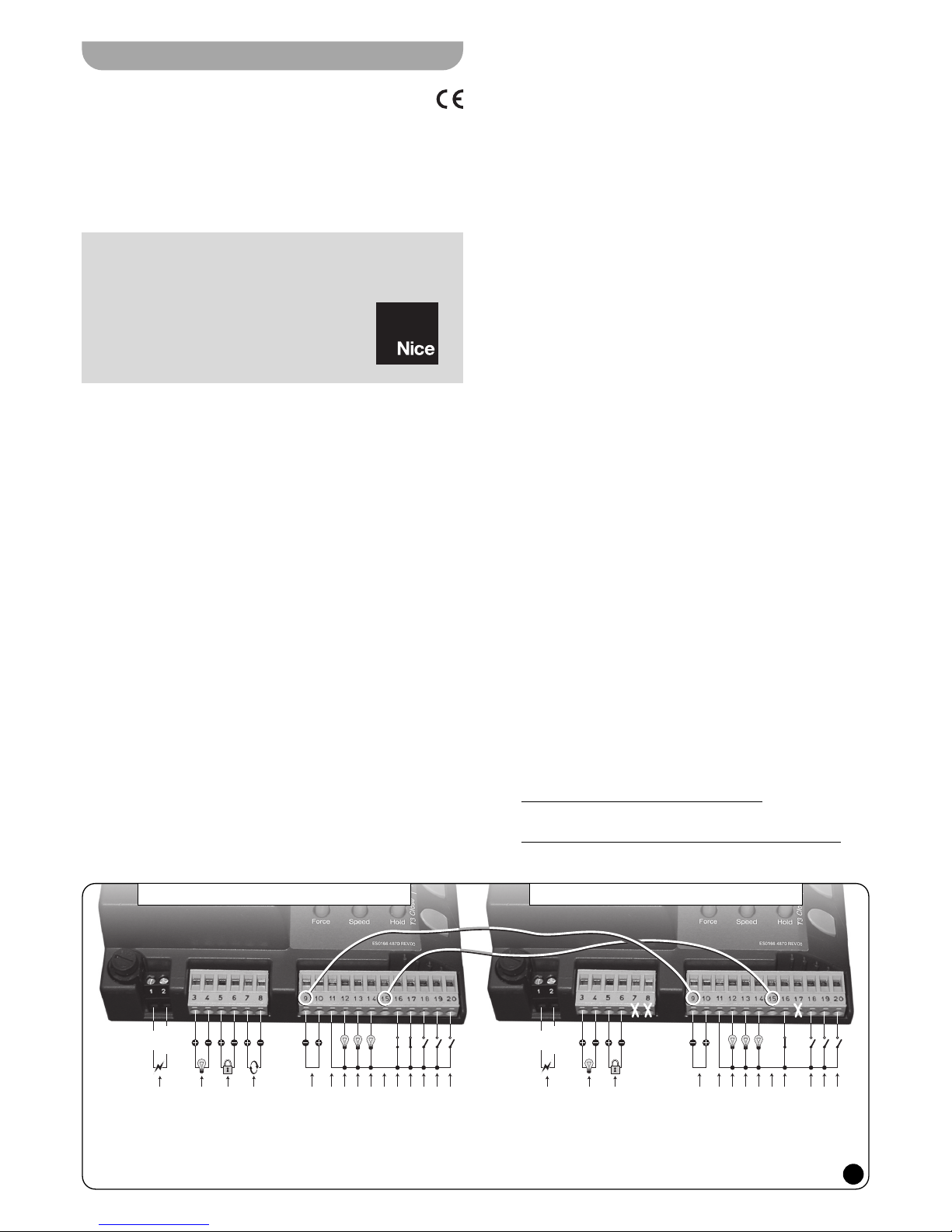
02. Connect the two control units together as illustrated in Fig. 1 and as
follows:
– connect the two terminals 9 (0 volt) of each control unit together.
– connect the two terminals 15 (sync) of each control unit together.
03. Then perform the other electrical connections referring to the
instructions in the instructions manuals of the two Signo. Also take
into account the following factors:
The following connections and adjustments can be made on
the MASTER-Control unit:
• Connection of a flashing light (for the entire system).
• Connection of an electric lock or suction cup (for Signo-Master
only).
• Connection of photocells for the entire system, with or without
“Phototest” control.
• Connection of LEDs to terminals 12 (Sca) and 13 (Cor) for the
entire system.
• Connection of a maintenance LED (for Signo-Master only).
• Connection of a safety device for the entire system, to terminal 16
(Stop). Note: if the terminal is not used it must be connected with
a jumper to terminal 11 (Common).
• Connection of one or more Photocells for the entire system, to
terminal 17 (Photo). Note: if the terminal is not used it must be
connected with a jumper to terminal 11 (Common.)
• Connection of control devices to terminals 18 (Step-by-Step), 19
(Open), 20 (Close), to open and close the two bars.
• Adjustment of the gearmotor power (for Signo-Master only).
• Adjustment of the pause time between the Opening and Closing
manoeuvres for the entire system.
The following connections and adjustments can be made on
the SLAVE-Control unit:
• Connection of a flashing light (for Signo-Slave only).
• Connection of an electric lock or suction cup (for Signo-Slave
only).
• Connection of LEDs to terminals 12 (Sca) and 13 (Cor) (for Signo-
Slave only).
• Connection of a maintenance LED (for Signo-Slave only).
• Connection of a safety device for the entire system, to terminal 16
(Stop). Note: if the terminal is not used it must be connected with
a jumper to terminal 11 (Common).
• Connection of control devices to terminals 18 (Step-by-Step), 19
(Open), 20 (Close), to open and close Signo-Slave only. Note:
The command is only performed once the Signo-Master bar is
closed.
The following operations can not be performed on the SLAVEControl unit:
• Use of terminals
8 (Phototest) and 17 (Photo).
The Photocells can be connected to the Master-Control unit only.
Terminal 17 (Photo) must be left free.
• Adjustment of the
pause time of the operation in Automatic. This
adjustment must be made on the Master-Control unit.
Power Supply:
230 VAC 50/60 HZ
Flashing Light:
24 Vcc, max 25 W
Electric Lock:
Phototest:
24 Vcc, max 200 mA
Services:
24 Vcc, max 200 mA
Common: 24 Vcc
(Sca)
(Cor)
(Man)
(Sinc)
(Stop)
(Photo)
(Open)
(Step-by-step)
(Close)
(Sca)
(Cor)
(fase)
(neutro)
Power Supply:
230 VAC 50/60 HZ
Flashing Light:
24 Vcc, max 25 W
Electric Lock:
Services:
Common: 24 Vcc
(Man)
(Sinc)
(Stop)
(Open)
(Step-by-step)
(Close)
(fase)
(neutro)
1
ENGLISH
Addendum to the Instructions
manual for the installation and use
Control unit “MASTER” (dip-switch 12 in OFF) Control unit “SLAVE” (dip-switch 12 in ON)

– 2 –
1 point
1
2
3
4
6° approx.
5
6
6
5
4
3
2
1
0 point
1 point
0 point
6° approx.
(OPENING manoeuvre) (CLOSING manoeuvre)
2
cedure” described in the Signo instructions manual (the set values
are saved in the memory).
04. Then position all Dip-switches to Off.
—— To adjust point RA ——
01. Set the Dip-switches as follows:
on -------4-------------- | -11---off -1-2-3--5-6-7-8-9-10- | - -12-
02. Then follow steps 02, 03 and 04 illustrated above to adjust point
RC.
NEW SIGNO STARTING SIGNAL MODE
This new signal occurs when Signo is started and signals that the control unit is on and operating correctly.
To verify this, turn the control unit on and check that the five LEDs next
to terminals 16, 17, 18, 19, 20 and the “Led Ok” rapidly flash immediately for a few seconds. Then check that the “LED Ok” continues to
flash regularly every second: This indicates that the control unit is
operating correctly.
NEW AUTOMATIC DIAGNOSTICS FUNCTION OF
THE OPERATIONAL FAULTS
This new function performs the automatic diagnostics of faults that the
Control unit encounters during the automation’s normal operations, and
signals the problem through a determined number of flashes of the “LED
Ok” (the diagnostic flashes always refer to the last action performed by
Signo).
Refer to the following table to understand the meaning of the number of
“LED Ok” flashes:
Note (*): Flashed 6 and 7 are only possible on the Master-Control unit.
N°✺
CAUSES
2
= Input from “Photo” or “Phototest” error
3
= Motor torque is not enough
4
= Input from “Stop”
5
= Error in Memory parameters
6*
= Error in Signo-Slave
7*
= Error in Signo-Master comunication
• Selection of the operational mode and Auxiliary Operations.
Only the “Electric lock / Suction cup” operations can be select-
ed with Dip-switch 8 on the Slave-Control unit. The other modes
and operations must be selected on the Master-Control unit.
Note: If Buffer batteries are used, each automation must have its
own battery.
04. Apply power to each of the Control units once the various electrical
connections have been completed, and perform procedure “3.10 –
checking the connections”, described in the two Signo instruction
manuals, on each of the control units.
05. Complete the Signo-Master installation by carrying out the “Testing”
procedure described in the two Signo instruction manuals. Once
completed, leave dip-switch 12 in OFF
(the Signo is assigned the
“Master” function with this setting).
06. Complete the Signo-Slave installation by carrying out the “5 - Test-
ing” procedure described in the two Signo instruction manuals.
Once completed, leave dip-switch 12 in ON
(the Signo is assigned
the “Slave” function with this setting).
NEW PROCEDURE FOR THE PERSONALISATION
OF THE BAR’S “MOVEMENT DECELERATION”
Warning! – This new procedure replaces the “4.3 – Manual pro-
gramming of deceleration positions”, present in the Signo instructions manual.
This new procedure allows choosing a point along the trajectory of the
bar at which the control unit must decelerate the bar during the opening
and closing manoeuvre before its movement stops against the mechanical stop.
In reference to Fig. 2, the distance in which the bar performs the “decel-
eration movement” is between points RA and
1 (during opening) and
points RC and
0 (during closure). The extent of these two distances is
automatically obtained by the control unit during the “4.1 – Mechanical
stop initial search” described in the Signo instructions manual. The values memorised during this search are defined in the factory on a scale
between 1 and 6 positions (1 = approx. 6°):
– point RA = position 2 (= approx. 12°);
– point RC = position 3 (= approx. 18°).
The initial set positions can be viewed by means of the following procedure that can be modified if necessary by increasing or decreasing the
position number for each of the two RA and RC points.
—— To adjust point RC ——
01. Set the Dip-switches as follows:
on -----3---------------- | -11---off -1-2--4-5-6-7-8-9-10- | - -12-
02. – To INCREASE the value of 1 position, push button “T1 Open”
once (each time the button is pushed the “LED Ok” flashes the
same number of times as the positions set up to that point).
– To DECREASE the value of 1 position, push button “T3 Close”
once (each time the button is pushed the “LED Ok” flashes the
same number of times as the positions set up to that point).
03. Once the choice has been made, follow procedure “4.4 – Save pro-
 Loading...