

Nice RONDO, RONDO RN2040, RONDO RN2040/V1 Instructions And Warnings For Installation And Use

Nice
RONDO
Balanced rolling door opener
EN - Instructions and warnings for installation and use

ENGLISH
Translation of the original instructions in full
CONTENTS
1 GENERAL SAFETY WARNINGS AND PRECAUTIONS . . . . . 2
1.1 General warnings . . . . . . . . . . . . . . . . . . . . . . . . . . . . . . . . . 2
1.2 Installation warnings . . . . . . . . . . . . . . . . . . . . . . . . . . . . . . . 3
2 PRODUCT DESCRIPTION AND INTENDED USE . . . . . . . . . 3
2.1 List of constituent parts . . . . . . . . . . . . . . . . . . . . . . . . . . . . . 3
3 INSTALLATION . . . . . . . . . . . . . . . . . . . . . . . . . . . . . . . . . . . . . 4
3.1 Pre-installation checks . . . . . . . . . . . . . . . . . . . . . . . . . . . . . 4
3.2 Product usage limits . . . . . . . . . . . . . . . . . . . . . . . . . . . . . . . 4
3.3 Product identification and overall dimensions . . . . . . . . . . . . 4
3.4 RECEIPT OF THE PRODUCT . . . . . . . . . . . . . . . . . . . . . . . . 4
3.5 Pre-installation works . . . . . . . . . . . . . . . . . . . . . . . . . . . . . . 5
3.6 Installing the gearmotor . . . . . . . . . . . . . . . . . . . . . . . . . . . . . 6
4 ELECTRICAL CONNECTIONS . . . . . . . . . . . . . . . . . . . . . . . . 8
4.1 Preliminary checks . . . . . . . . . . . . . . . . . . . . . . . . . . . . . . . . 8
4.2 Wiring diagram and description of connections . . . . . . . . . . . 8
5 FINAL CHECKS AND START-UP. . . . . . . . . . . . . . . . . . . . . . . 9
5.1 Adjusting the mechanical limit switches . . . . . . . . . . . . . . . . . 9
5.2 Manually unlocking and locking the gearmotor . . . . . . . . . . . 9
6 TESTING AND COMMISSIONING. . . . . . . . . . . . . . . . . . . . . . 9
6.1 Testing . . . . . . . . . . . . . . . . . . . . . . . . . . . . . . . . . . . . . . . . . 9
6.2 Commissioning . . . . . . . . . . . . . . . . . . . . . . . . . . . . . . . . . . . 9
7 TROUBLESHOOTING GUIDE . . . . . . . . . . . . . . . . . . . . . . . . 10
7.1 Troubleshooting . . . . . . . . . . . . . . . . . . . . . . . . . . . . . . . . . 10
8 PRODUCT MAINTENANCE. . . . . . . . . . . . . . . . . . . . . . . . . . 11
9 PRODUCT DISPOSAL . . . . . . . . . . . . . . . . . . . . . . . . . . . . . . 11
10 TECHNICAL SPECIFICATIONS. . . . . . . . . . . . . . . . . . . . . . . 12
11 CONFORMITY . . . . . . . . . . . . . . . . . . . . . . . . . . . . . . . . . . . . 13
INSTRUCTIONS AND WARNINGS FOR THE USER. . . . . . 15
1
1 GENERAL SAFETY WARNINGS AND PRECAUTIONS
1.1 GENERAL WARNINGS
a
a
a
PRECAUTIONS
Prior to installing the appliance, carefully read and
observe these instructions, since incorrect installation can cause serious harm to people and damage
to the appliance. Store them with care.
According to the latest European legislation, an automated device must be constructed in conformity
to the harmonised rules specied in the current
Machinery Directive, which allow for declaring the
presumed conformity of the automation. Consequently, all the operations for connecting the product to the mains electricity, its commissioning and
maintenance must be carried out exclusively by a
qualied and expert technician.
In order to avoid any danger from inadvertent resetting of the thermal cut-off device, this appliance
must not be powered through an external switching
device, such as a timer, or connected to a supply
that is regularly powered or switched off by the circuit.
WARNING! Please abide by the following warnings:
– Before commencing the installation, check the “Product
technical specications”, in particular whether this product is suitable for automating your guided part. Should it
not be suitable, do NOT proceed with the installation.
– The product cannot be used before it has been commis-
sioned as specied in the “Testing and commissioning”
chapter.
– Before proceeding with the product’s installation, check
that all the materials are in good working order and suited
to the intended applications.
– The product is not intended for use by persons (including
children) with reduced physical, sensory or mental capacities, nor by anyone lacking sufcient experience or famil-
iarity with the product.
– Children must not play with the appliance.
– Do not allow children to play with the product’s control
devices. Keep the remote controls out of reach of chil-
dren.
– The system’s power supply network must include a dis-
connection device (not supplied) with a contact opening
gap permitting complete disconnection under the condi-
tions envisaged by Overvoltage Category III.
– During the installation process, handle the product with
care by avoiding crushing, impacts, falls or contact with
liquids of any kind. Do not place the product near sources
of heat nor expose it to open ames. All these actions can
damage the product and cause it to malfunction, or lead
to dangerous situations. Should this occur, immediately
suspend the installation process and contact the Techni-
cal Assistance Service.
– The manufacturer declines all liability for damages to
property, objects or people resulting from failure to ob-
serve the assembly instructions. In such cases, the war-
ranty for material defects shall not apply.
– The weighted sound pressure level of the emission A is
lower than 70 dB(A).
GENERAL SAFETY WARNINGS AND
2 – ENGLISH

– Cleaning and maintenance reserved for the user must not
C
F
A
be carried out by unsupervised children.
– Before intervening on the system (maintenance, cleaning),
always disconnect the product from the mains power
supply and from any batteries.
– Inspect the system frequently, in particular the cables,
springs and supports to detect any imbalances and signs
of wear or damage. Do not use the product if it needs to
be repaired or adjusted, because defective installation or
incorrect balancing of the automation can lead to injuries.
– The packing materials of the product must be disposed of
in compliance with local regulations.
– The product must not be installed outdoors.
– Keep an eye on moving doors and do not let anyone go
near them until they have opened or closed fully.
– Be careful when activating the manual unlocking device
(manual manoeuvre), as an open door may fall suddenly
due to weak or broken springs, or if it is unbalanced.
– Every month, check that the drive motor reverses when
the door encounters a 50 mm-high object placed on the
ground. If necessary, readjust the door and check it again,
as incorrect adjustment is potentially dangerous (for drive
motors incorporating a trapping safety system that inter-
venes when the door's lower edge encounters an obsta-
cle).
– Motor with xed power cable: the power cable cannot
be replaced. If the cable is damaged, the appliance must
be scrapped.
– Motor with removable power supply cable with dedicat-
ed connector: if the power supply cable is damaged, it
must be replaced by the manufacturer or by the latter’s
technical assistance service, or nonetheless by a similarly
qualied person, so as to prevent any risk.
1.2 INSTALLATION WARNINGS
– Prior to installing the drive motor, check that the door is in
good working order, correctly balanced and that it opens
and closes properly.
– Prior to installing the drive motor, remove all unnecessary
cables or chains and deactivate any equipment, such as
the locking devices,
– Check that there are no points where people could get
trapped or crushed against xed parts when the door is
fully open or closed; if there are, arrange adequate pro-
tective measures for these parts.
– Install the manoeuvre device for manual unlocking at less
than 1.8 m above the ground. NOTE - If removable, the
manoeuvre device must be kept next to the door when
removed.
– Make sure that the control elements are kept far from
moving parts but nonetheless directly within sight. Unless
a selector is used, the control elements must be installed
at least 1.5 m above the ground and must not be acces-
sible.
– Permanently attach the trapping hazard warning labels in
a highly visible location or near the xed control devices
(if present).
– Permanently attach the manual unlock (manual manoeu-
vre) label close to the manoeuvring element.
– After installation, make sure that the motor prevents or
stops opening of the door when the latter is loaded with a
20-kg weight secured to the centre of its bottom edge (for
drive motors that can be used with doors having opening
widths exceeding 50 mm).
– After installation, make sure that the mechanism is prop-
erly adjusted and that the motor reverses when the door
collides with a 50 mm-tall object placed on the ground (for
drive motors incorporating a trapping safety system that
intervenes when the bottom edge of the door encounters
an obstacle). Following installation, check and ensure that
no door parts obstruct public roadways or pavements.
PRODUCT DESCRIPTION AND
2
2 PRODUCT DESCRIPTION AND INTENDED USE
RONDO is a gearmotor for spring-balanced rolling shutters. It
allows for automating shutters with a maximum height 6 m and
weight up to 170 kg.
The gearmotor can be mounted on shutters with spring support
shaft having a 42 mm, 48 mm or 60 mm diameter.
The spring support boxes can have a 200 mm or 220 mm diameter. The two collars are made of die-cast aluminium.
It has a limit switch with micrometer screw and mechanical position
memory.
The unlocking device, operated from the ground, disengages the
motor from the gearmotor body and is only available for models
with electric brake.
a
2.1 LIST OF CONSTITUENT PARTS
"Figure 1" shows the main parts making up the RONDO.
A Half-collar
B Transmission shaft housing
C Adaptor for collar
D Gearmotor body
E Limit switch position regulators
F Locking/unlocking system (where congured)
G Electric brake (where congured)
INTENDED USE
Any use of the product other than the intended use
described is not allowed!
1
G
B
E
D
ENGLISH – 3

3
Ø 220 mm
A
DC E F
3 INSTALLATION
INSTALLATION
3.1 PRE-INSTALLATION CHECKS
The installation must be carried out by qualied
a
personnel in compliance with the current legislation, standards and regulations, and with the instructions provided in this manual.
Before proceeding with the product’s installation, it is necessary to:
– check the integrity of the supply
– check that all the materials are in good working order and suited
to the intended use
– check that the shutter is properly balanced, in other words, it
must not start moving again when stopped in any position
– verify that there are no points of greater friction during the open-
ing and closing movements along the entire shutter path
– verify that the shutter moves silently and smoothly along its path
– verify that the xing zone is compatible with the product’s size
(see paragraph “Product identication and overall dimen-
sions“).
– verify that the mounting positions of the various devices are pro-
tected against impacts and that the mounting surfaces are suf-
ciently sturdy
– prevent any parts of the automation from being immersed in wa-
ter or other liquids
– keep the product away from heat sources and open ames and
acid, saline or potentially explosive atmospheres; these may
damage the product and cause malfunctions or dangerous sit-
uations
– connect the control unit to an electricity supply line equipped
with a safety earthing system
– include a device on the electric power line ensuring complete
disconnection of the automation from the grid. The disconnec-
tion device must have contacts with a sufcient gap to ensure
complete disconnection, under the Category III overvoltage con-
ditions, in accordance with the installation instructions. Should it
be necessary, this device guarantees fast and safe disconnection
from the power supply; it must therefore be positioned in view of
the automation. If placed in a non-visible location, it must have a
system that blocks any accidental on unauthorised reconnection
of the power supply, in order to prevent dangerous situations.
The disconnection device is not supplied with the product.
3.2 PRODUCT USAGE LIMITS
The data relative to the product’s performances is included in the
“TECHNICAL SPECIFICATIONS” chapter and is the only data
that allows for properly assessing whether the product is suitable
for its intended use.
Check the application limits of RONDO and of the accessories to
be installed, assessing whether their characteristics are capable of
meeting the requirements of the environment and the limitations
specied below:
– verify that the weight of the shutter does not exceed the value
stated in the "TECHNICAL SPECIFICATIONS" chapter
– the door dimensions must be below 20 m2
– the drive shaft must be compatible with the RONDO output and
the relative keys supplied with the package.
The gearmotor is equipped with a thermal cut-off which, in case
of overheating caused by overuse of the automation (beyond the
specied limits), automatically cuts off the electricity supply, restoring it as soon as the temperature returns to its normal value.
The control unit is equipped with a manoeuvre lim-
a
iting device that prevents possible overheating; it is
based on the motor load and duration of the cycles,
and intervenes when the maximum limit is exceeded.
3.3 PRODUCT IDENTIFICATION AND OVERALL DIMENSIONS
The overall dimensions and the label (A), which allows for identifying the product, are shown in "Figure 2".
2
320 mm
A
350 mm (230V)
370 mm (120V)
3.4 RECEIPT OF THE PRODUCT
All the components contained in the product’s packaging are illustrated and listed below.
3
A
B
A Gearmotor
B Electric brake (where congured)
C Adaptor for collar
D Adaptor for spring support shaft size 48 mm
E User manual
F Power cable
4 – ENGLISH

3.5 PRE-INSTALLATION WORKS
The gure shows an example of an automation system, constructed using Nice components.
4
D
3
1
C
2
B
A
A Spring support box
B Spring support shaft
C Gearmotor
D Junction box
E Locking/unlocking knob
F Command inverter
The above-mentioned components are positioned according to a
typical standard layout. Using the layout shown in "Figure 4" for
reference, dene the approximate position in which each component of the system will be installed.
Table 1
TECHNICAL SPECIFICATIONS OF ELECTRICAL CABLES
Identication
no.
1
2
Cable characteristics
GEARMOTOR POWER SUPPLY cable
1 cable 4 x 0.75 mm
Maximum length 30 m [note 1]
PUSHBUTTON PANEL cable
1 cable 3 x 0.75 mm
2
2
minimum
E
Note 1 If the power supply cable is longer than 30 m, a cable with
larger cross-sectional area (3 x 2.5 mm
F
2
) must be used
and a safety earthing system must be installed near the
automation.
The cables used must be suited to the type of envi-
a
ronment of the installation site.
ENGLISH – 5

3.6 INSTALLING THE GEARMOTOR
12 mm
Incorrect installation may cause serious physical
a
injury to the person working on the system or to its
future users.
Before starting to assemble the automation, complete the preliminary checks described in the “Pre-
installation checks” and “Product usage limits”
paragraphs.
To install RONDO:
1. close the shutter completely
2. cut the three holes specied in the image on the spring sup-
port shaft
5
=
50 mm
Ø 10 mm
=
500 mm
Ø 12 mm
4. dismantle the two half-collars (B) by loosening the screws
(C)
7
C
B
B
C
550 mm
Ø
3. loosen the screw (A) and remove the washer
6
A
5. gently remove the roller band (D) without bending it, as the
rollers could fall off
8
D
6 – ENGLISH

6. separate the item (E) by loosening the four screws (F)
The sleeves (G) on the gearmotor are suitable for
m
a spring support shaft with 48 mm diameter. If the
shutter shaft has a smaller diameter, replace the
sleeves with other sleeves having a 33 or 42 mm
diameter (not supplied) and place them against the
10 mm hole cut previously (see “Figure 5“).
9
F
E
G
9. tighten the M10 screw (J) with the nut supplied (K) to lock
the gearmotor on the spring support shaft; tighten the nut to
lock the screw in position
11
J
K
10. mount the roller band back on without bending it, as the
rollers could fall off
11. mount the two half-collars back on with the appropriate
screws
12. if there are any spring support boxes with a 220 mm diam-
eter, mount the adaptor supplied (L) using the appropriate
at-head screw (M)
7. draw the gearmotor against the spring support shaft and
couple it with item (E) using the four screws (F) removed
previously
8. completely tighten the M10 screw supplied (H) without the
hexagonal nut, until it penetrates into the spring support
shaft through the 10 mm hole
10
H
F
E
H
12
L
M
13. cut a 12 mm hole on the last item of the shutter near the hole
on the half-collar (B)
14. fasten the last item of the shutter to the gearmotor using
screw (A) and the appropriate washer
Ø10 mm
ENGLISH – 7

13
12 mm
Ø 12 mm
50 Hz
Ø 12 mm
15
Ø
A
B
4
4 ELECTRICAL CONNECTIONS
ELECTRICAL CONNECTIONS
4.1 PRELIMINARY CHECKS
All electrical connections must be made with the
f
system disconnected from the mains electricity and
with the back-up battery (if present) disconnected.
The connection operations must only be carried out
a
by qualied personnel.
To make the electrical connections:
1. remove the screws and the protective cover (A)
4. make the connections by following the scheme shown in
"Figure 16"
5. after making the connections, lock the power cable by
screwing the protective cover (A) in place.
4.2 WIRING DIAGRAM AND DESCRIPTION OF CONNECTIONS
16
B
A
NL
C
230 Vac
14
A
2. pass the power cable through the hole cut previously on the
spring support shaft
3. if the gearmotor is equipped with an electric brake, t the
brake sheath through the second hole on the spring support
shaft
A Mains power inputs terminal
B Manual command buttons
C Omnipolar device
8 – ENGLISH
5
5 FINAL CHECKS AND START-UP
FINAL CHECKS AND START-UP
6 TESTING AND COMMISSIONING
2. at this point, the shutter can be moved manually to the desired position.
To lock the device, turn the knob clockwise all the way.
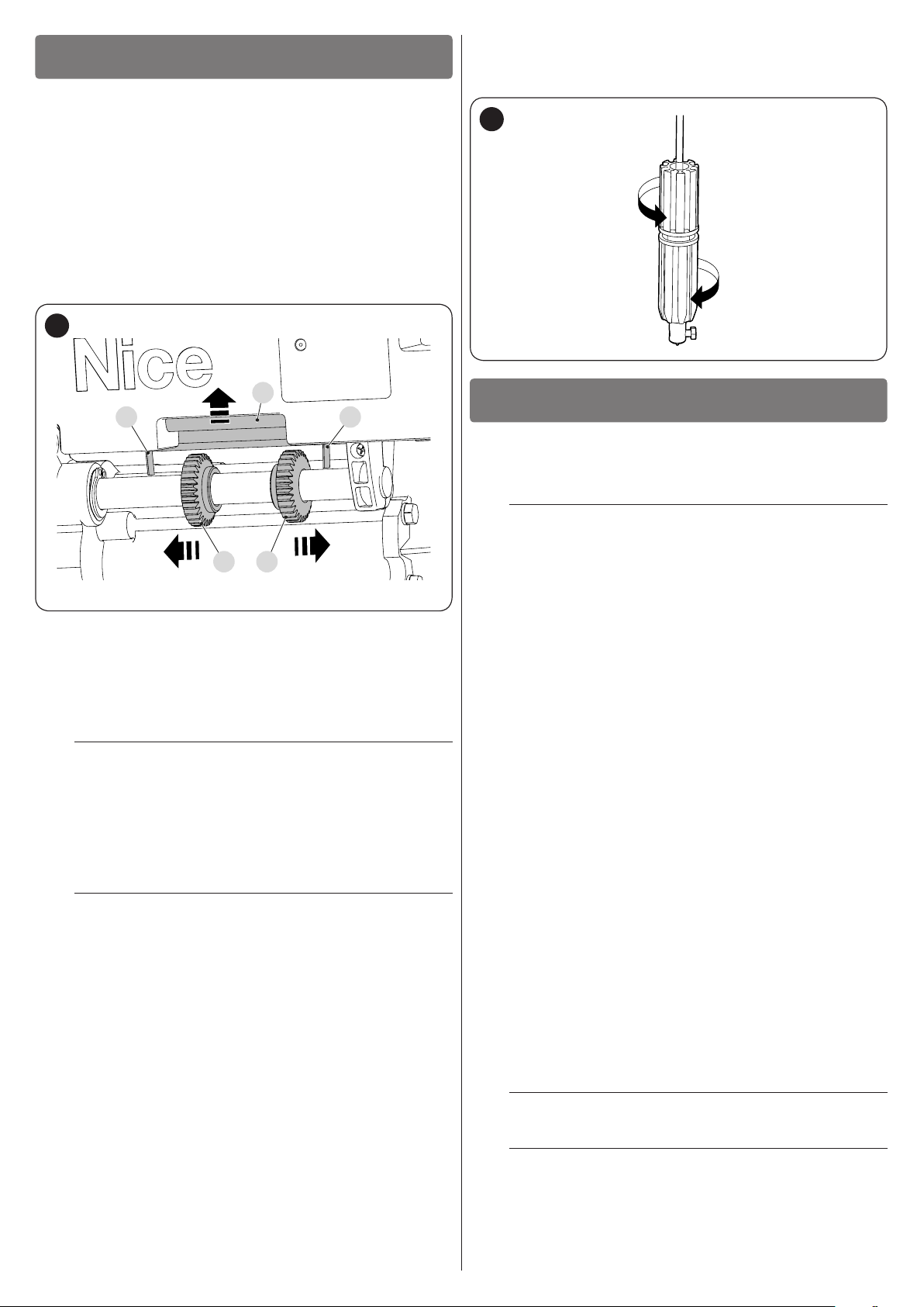
5.1 ADJUSTING THE MECHANICAL LIMIT SWITCHES
To adjust the limit switches, proceed as follows:
1. close the shutter completely
2. press and hold the presser (A) upwards so as to allow the
limit switch adjusters to move freely
3. turn the adjuster (B) until the lowering switch (C) clicks (lowering limit switch adjustment completed)
4. turn the adjuster (D) by moving it towards the lifting switch
(E)
5. release the presser (A)
17
A
EC
DB
6. power the gearmotor
7. control the lowering of the shutter through the key selector
or button
8. verify whether the shutter stops in the desired position
9. to allow the shutter to stop in a different position during the
opening movement, change the position of the adjuster (D)
as shown previously
If the gearmotor is installed in the opposite direc-
m
tion, switch (C) will allow the shutter to stop while it
is lifted, while switch (E) will allow it to stop while it
is lowered. Adjust the cursors accordingly.
5.2 MANUALLY UNLOCKING AND LOCKING THE GEARMOTOR
If the shutter is lifted before the limit switches are
a
adjusted, the gearmotor could get seriously damaged. Carry out the procedure set forth in the "Ad-
justing the mechanical limit switches" paragraph.
Gearmotors equipped with an electric brake have a mechanical
unlocking system that allows for opening and closing the shutter
manually.
These manual operations should only be performed in case of a
power outage, malfunctions or during the installation phases.
To unlock the device:
1. loosen the lower part of the knob anti-clockwise until you
can
18
6
These are the most important phases of the automation’s con-
struction, as they ensure maximum safety of the system. The test
can also be used to periodically verify the devices making up the
automation.
m
The additional devices must undergo specic testing, both in terms
of their functions and their proper interaction with the control unit.
Refer to the instruction manuals of the individual devices.
TESTING AND COMMISSIONING
Testing and commissioning of the automation must
be performed by skilled and qualied personnel,
who are responsible for the tests required to verify the solutions adopted according to the risks
present, and for ensuring that all legal provisions,
standards and regulations are met, in particular all
the requirements of the EN 12445 standard, which
denes the test methods for checking door automations.
6.1 TESTING
To run the test:
1. verify that all the instructions stated in the “GENERAL
SAFETY WARNINGS AND PRECAUTIONS” chapter have
been strictly observed
2. check that the die-cast items are in good condition and are
not broken
3. check that the gearmotor is properly secured to the spring
support shaft
4. check that the electrical contacts are in good condition
5. check that the collar does not have any excessive axial
clearance
6. verify the adjustment of the limit switches by performing a
complete manoeuvre (up-down)
7. check that the gearmotor – when locked in any position –
does not move
8. check that the unlocking manoeuvre easily disengages the
gearmotor from the shutter (only for versions with brake).
6.2 COMMISSIONING
Commissioning can only be performed after all
a
testing phases have been successfully completed.
Before commissioning the automation, ensure that
a
the owner is properly informed of all residual risks
and hazards.
ENGLISH – 9

The gate cannot be commissioned partially or un-
a
der “temporary” conditions.
To commission the automation:
1. compile the automation’s technical le, which must include
the following documents: overall drawing of the automation, wiring diagram, risk assessment and relative solutions
adopted, the manufacturer’s declaration of conformity for all
devices used and the declaration of conformity compiled by
the installer
2. permanently afx a label or plate near the manual manoeu-
vre knob, indicating the operations for unlocking the shutter
“Figure 19“
19
3. permanently afx a label or sign to the door with the follow-
ing image (minimum height 60 mm) “Figure 20“
20
4. afx a label to the door containing at least the following data:
type of automation, name and address of manufacturer (person responsible for commissioning), serial number, year of
manufacture and the CE mark
5. compile the declaration of conformity of the automation and
hand it to the owner of the automation
6. compile the User Manual of the automation and hand it to
the owner of the automation
7. compile and provide the owner with the automation’s “Main-
tenance schedule”, containing the maintenance instructions
for all the automation’s devices.
For all the above-mentioned documentation, Nice –
l
through its technical assistance service – provides
the following: pre-completed forms.
TROUBLESHOOTING...
7
7 TROUBLESHOOTING GUIDE
7.1 TROUBLESHOOTING
The table below contains useful instructions to resolve any malfunctions or errors that may occur during installation or in case of a fault.
TROUBLESHOOTING
Problems Recommended checks
The motor does not start
The shutter does not stop in the pre-dened
positions
The manual manoeuvre knob is unlocked, but the
shutter cannot be lifted
The thermal cut-off was activated The motor has overheated: wait until its normal temperature is restored.
The motor struggles to lift the shutter
(troubleshooting guide)
Table 2
Verify that the connections shown in the electrical diagram are correct.
If the motor is equipped with an electric brake, verify that it is properly connected to
the limit switch casing.
On the version without brake, a jumper must be connected between the two
terminals.
Verify that the limit switch is properly adjusted as set forth in the "Adjusting the
mechanical limit switches" paragraph.
Verify that the cord of the electric brake was suitably tensioned during the
installation phase.
Verify that the spring support boxes are not damaged.
Verify that the size and weight of the shutter are compatible with the gearmotor’s
installation.
Verify the correct operation of the spring support boxes.
10 – ENGLISH

8
8 PRODUCT MAINTENANCE
a
To service the gearmotor, repeat the testing procedure from beginning to end.
PRODUCT MAINTENANCE
Maintenance must be carried out strictly in compliance with the safety provisions provided in this
manual and in accordance with the laws and regulations in force.
9
9 PRODUCT DISPOSAL
l
As with the installation, only qualied personnel must dismantle the
product at the end of its life.
This product is composed of different types of materials. Some
of these materials can be recycled; others must be disposed of.
Please enquire about the recycling or disposal systems in place in
your local area for this type of product.
a
l
PRODUCT DISPOSAL
This product is an integral part of the operator and
must therefore be disposed of with it.
WARNING
Some parts of the product may contain polluting or
dangerous substances. If not disposed of correctly,
these substances may have a damaging effect on
the environment and human health.
As indicated by the symbol shown
here, this product must not been
disposed of with household
waste. Separate the waste for disposal and recycling, following the
methods stipulated by local regulations, or return the product to
the seller when purchasing a new
product.
WARNING
a
Local regulations may impose heavy penalties if
this product is not disposed of in compliance with
the law.
ENGLISH – 11

10
10 TECHNICAL SPECIFICATIONS
l
TECHNICAL SPECIFICATIONS
All technical specications stated in this section refer to an ambient temperature of 20°C (± 5°C). Nice S.p.A.
reserves the right to apply modications to the product at any time when deemed necessary, without altering
its functions and intended use.
TECHNICAL SPECIFICATIONS
Description Technical specication
RN2040 RN2040/V1
Product type Gearmotor for spring-balanced rolling shutters
Power supply
Maximum current draw (A) 2,7 5,2
Maximum torque (Nm) 170
Maximum power consumption (W) 630 610
Maximum speed (rpm) 10
Protection rating (IP) 20
Operating temperature (min/max °C) -20°C ÷ 50°C
Maximum shutter height (m) 7
Lifting capacity (kg) 170
Cycles per hour at the rated torque – for shutters
with 3 m height (cycles/hour)
Dimensions (mm) Ø220 x 350 Ø220 x 370
Weight (kg) 7 8
Emergency power supply No
Use in highly acid, saline or potentially explosive
atmosphere
230Va (+10% -15%) 50 Hz 120Va (+10% -15%) 60 Hz
1
No
Table 3
12 – ENGLISH

11
EU Declaration of Conformity
Note - The contents of this declaration correspond to declarations in the ofcial document deposited at the registered ofces of Nice S.p.a. and in particular to the last revision available before
printing this manual. The text herein has been re-edited for ed
Number:
Manufacturer’s Name:
Address:
Authorized Person to constitute
technical documentation:
Type of product:
Model/Type:
Accessories:
The undersigned Roberto Griffa, in the role of Chief Executive Ofcer, declares under his sole responsibility that the product described above complies with the provisions
laid down in the following directives:
•
The product also complies with the following directives according to the requireme
•
It is hereby stated that the relevant technical documentation has been compiled in accordance with annex VII B of Directive 2006/42/EC and that the following essential
requirements have been fullled: 1.1.1 - 1.1.2 - 1.1.3 - 1.2.1 - 1.2.6 - 1.5.1 - 1.5.2 The manufacturer undertakes to transmit to the national authorities, in response to a reasoned request, the relevant information on the “ partly completed machinery “, while
maintaining full rights to the related intellectual property.
Should the “ partly completed machinery” be put into service in a European country with an ofcial language other than that used in this declaration, the importer is obliged
to arrange for the relative translation to accompany this declaration.
The “partly completed machinery” must not be used until the nal machine in which it is incorporated is in turn declared as compliant, if applicable, with the provisions of
directive 2006/42/EC.
The product also complies with the following standards:
EN 60335-1:2012+A11:2014, EN 62233:2008, EN 60335-2-103:2015
Oderzo,
Ing. Roberto Griffa
(Chief Executive Ofcer)
11 CONFORMITY
CONFORMITY
and declaration of incorporation of “partly completed machinery”
itorial purposes. A copy of the original declaration can be requested from Nice S.p.a. (TV) I.
168/RN
Rev: 8 Language: EN
Via Callalta 1, 31046 Oderzo (TV) Italy
Nice s.p.a.
“RONDO” electromechanical gearmotor for balanced shutters
Nice s.p.a.
RN2040
Refer to the catalog
Directive 2014/30/EU (EMC), according to the following harmonized standards: EN 61000-6-2:2005, EN 61000-6-3:2007+A1:2011
Directive 2006/42/EC of the EUROPEAN PARLIAMENT AND COUNCIL of 17 May 2006 related to machinery and amending the Directive 95/16/EC (recast).
07/05/2019
nts envisaged for “partly completed machinery” (Annex II, part 1, section B):
1.5.5 - 1.5.6 - 1.5.7- 1.5.8 - 1.5.10 - 1.5.11
ENGLISH – 13

NOTES
14 – ENGLISH

&
INSTRUCTIONS AND WARNINGS FOR THE USER
Before using the automation for the rst time, ask the installer to
explain the origin of any residual risks and take a few minutes to
read this instruction manual and warnings for the user given to you
by the installer. Store the manual for future reference and hand it to
the new owner when transferring the automation.
WARNING!
a
Your automation is a machine that faithfully executes commands imparted by the user. Negligence
and improper use may lead to dangerous situations:
– do not manoeuvre the gate if there are people, animals or
objects within its range of operation
– it is strictly forbidden to touch parts of the automation
while it is moving.
IT IS STRICTLY FORBIDDEN to transit while the au-
a
tomation is closing! Transit is allowed only if the automation is fully open and stationary.
CHILDREN
a
An automation system guarantees a high degree
of safety. With its detection systems, it can control
and guarantee the gate’s movement in the presence
of people or objects. It is nonetheless advisable to
forbid children from playing near the automation
and not to leave remote controls near them to prevent any unwanted activation of the system. The
automation is not a toy!
The product is not intended for use by persons, including children, with limited physical, sensory or
mental capacities, or who lack experience or knowledge, unless supervised or trained in the use of the
product by a person responsible for their safety.
Anomalies: if the automation shows any signs of anomalous be-
haviour, disconnect the power supply to the system and manually
unlock the motor (see instructions at the end of the chapter) to
manoeuvre the automation manually. Do not attempt any repairs
personally, but contact your trusted installer.
Failure or lack of power supply: while waiting for the installer
to intervene or the electricity to be restored, if the system is not
equipped with back-up batteries, the automation can nonetheless
be used by manually unlocking the motor (see the instructions at
the end of the chapter) and moving the automation manually.
Do not modify the system: the responsibility lies on
l
your installer.
Testing, periodic maintenance and any repairs must be documented by the person performing the operations and the relative documents must be kept by the owner of the installation.
Before carrying out any maintenance operations,
m
the user of the automation must manually unlock
the motor to prevent anyone from accidentally triggering the automation’s movement (see the instructions at the end of the chapter).
Maintenance: in order to ensure constant levels of safety and the
longest useful life for the automation, routine maintenance must be
carried out (at least every 6 months).
Only qualied personnel is authorised to carry out
l
checks, maintenance operations and repairs.
Disposal: at the end of its useful life, the automation must be dis-
mantled by qualied personnel and the materials must be recycled
or disposed of in compliance with the local regulations in force.
Unlocking and manual movement
The device can only be unlocked once the automa-
a
tion is stationary.
Gearmotors equipped with an electric brake have a mechanical
unlocking system that allows for opening and closing the shutter
manually.
These manual operations should only be performed in case of a
power outage, malfunctions or during the installation phases.
To unlock the device:
1. loosen the lower part of the knob anti-clockwise until you
can
2. at this point, the shutter can be moved manually to the de-
sired position.
21
&
To lock the device, turn the knob clockwise all the way.
ENGLISH – 15

Nice SpA
Via Callalta, 1
31046 Oderzo TV Italy
info@niceforyou.com
IDV0726A00EN_31-05-2019
www.niceforyou.com
 Loading...