


Instructions and warnings for the fitter
Istruzioni ed avvertenze per l’installatore
Instructions et recommandations pour l’installateur
Anweisungen und Hinweise für den Installateur
Instrucciones y advertencias para el instalador
Instrukcje i uwagi dla instalatora
Aanwijzingen en aanbevelingen voor de installateur
For sliding gates
Robus
600/600P
1000/1000P

2
Table of contents: page
1 Warnings 3
2 Product description and applications 4
2.1 Operating limits 4
2.2 Typical system 6
2.3 List of cables 6
3 Installation 7
3.1 Preliminary checks 7
3.2 Installation of the gearmotor 7
3.3 Fixing of the limit switch bracket
on versions with inductive limit switch 8
3.4 Installation of the various devices 9
3.5 Electrical connections 9
3.6 Description of the electrical connections 10
4 Final checks and start up 10
4.1 Choosing the direction 10
4.2 Power supply connection 10
4.3 Recognition of the devices 10
4.4 Recognizing the length of the leaf 11
4.5 Checking gate movements 11
4.6 Preset functions 11
4.7 Radio receiver 11
5 Testing and commissioning 11
5.1 Testing 12
5.2 Commissioning 12
6 Maintenance and Disposal 12
6.1 Maintenance 12
6.2 Disposal 12
7 Additional information 13
7.1 Programming keys 13
7.2 Programming 13
7.2.1 Level one functions (ON-OFF functions) 13
7.2.2 Level one programming
(ON-OFF functions) 14
7.2.3 Level two functions
(adjustable parameters) 14
7.2.4 Level two programming
(adjustable parameters) 15
7.2.5 Level one programming example
(ON-OFF functions) 16
7.2.6 Level two programming example
(adjustable parameters) 16
7.3 Adding or removing devices 16
7.3.1 BlueBUS 16
7.3.2 STOP input 17
7.3.3 Photocells 17
7.3.4 FT210B Photo-sensor 17
7.3.5 ROBUS in “Slave” mode 18
7.3.6 Recognition of Other Devices 19
7.4 Special functions 19
7.4.1 “Always open” Function 19
7.4.2 “Move anyway” function 19
7.4.3 Maintenance warning 19
7.5 Connection of Other Devices 20
7.6 Troubleshooting 21
7.6.1 Malfunctions archive 21
7.7 Diagnostics and signals 21
7.7.1 Flashing light signalling 22
7.7.2 Signals on the control unit 22
7.8 Accessories 23
8 Technical characteristics 24
Instructions and Warnings for users of
ROBUS gearmotor 25
Robus
600/600P
1000/1000P

3
1) Warnings
This manual contains important information regarding safety. Before you
start installing the components, it is important that you read all the information contained herein. Store this manual safely for future use.
Due to the dangers which may arise during both the installation and use
of the ROBUS, installation must be carried out in full respect of the laws,
provisions and rules currently in force in order to ensure maximum safety. This chapter provides details of general warnings. Other, more specific warnings are detailed in Chapters “3.1 Preliminary Checks” and “5
Testing and Commissioning”.
According to the most recent European legislation, the
automation of doors or gates is governed by the provisions
listed in Directive 98/37/CE (Machine Directive) and, more
specifically, to provisions: EN 13241-1 (harmonised standard);
EN 12445; EN 12453 and EN 12635, which enables to declare
the conformity to the machine directive.
Please access “www.niceforyou.com” for further information, and guidelines for risk analysis and how to draw up the Technical Documentation.
This manual has been especially written for use by qualified fitters.
Except for the enclosed specification “Instructions and Warnings for
Users of the ROBUS gearmotor” which is to be removed by the installer,
none of the information provided in this manual can be considered as
being of interest to end users!
• Any use or operation of ROAD200 which is not explicitly provided for
in these instructions is not permitted. Improper use may cause damage and personal injury.
• Risk analysis must be carried out before starting installation, to include
the list of essential safety requisites provided for in Enclosure I of the
Machine Directive, indicating the relative solutions employed.
Risk analysis is one of the documents included in the “Technical Documentation” for this automation.
• Check whether additional devices are needed to complete the
automation with ROBUS based on the specific application requirements and dangers present. The following risks must be considered:
impact, crushing, shearing, dragging, etc. as well as other general
dangers.
• Do not modify any components unless such action is specified in this
manual. Operations of this type are likely to lead to malfunctions. NICE
disclaims any liability for damage resulting from modified products.
• During installation and use, ensure that solid objects or liquids do not
penetrate inside the control unit or other open devices. If necessary,
please contact the NICE customer service department; the use of
ROBUS in these conditions can be dangerous.
• The automation system must not be used until it has been commis-
sioned as described in chapter 5 “Testing and commissioning”.
• The ROBUS packing materials must be disposed of in compliance
with local regulations.
• If a fault occurs that cannot be solved using the information provided
in this manual, refer to the NICE customer service department.
• In the event that any automatic switches are tripped or fuses blown,
you must identify the fault and eliminate it.
• Disconnect all the power supply circuits before accessing the terminals
inside the ROBUS cover. If the disconnection device is not identifiable,
post the following sign on it: “WARNING: MAINTENANCE WORK IN
PROGRESS”.
Particular warnings concerning the suitable use of this product in relation
to the 98/37CE “Machine Directive” (ex 89/392/EEC):
• This product comes onto the market as a “machine component” and
is therefore manufactured to be integrated to a machine or assembled
with other machines in order to create “a machine”, under the directive
98/37/EC, only in combination with other components and in the manner described in the present instructions manual. As specified in the
directive 98/37CE the use of this product is not admitted until the manufacturer of the machine on which this product is mounted has identified and declared it as conforming to the directive 98/37/CE.
Particular warnings concerning the suitable use of this product in relation
to the 73/23/EEC “Low Voltage” Directive and subsequent modification
93/68/EEC:
• This product responds to the provisions foreseen by the “Low Voltage”
Directive if used in the configurations foreseen in this instructions manual and in combination with the articles present in the Nice S.p.a. product catalogue. If the product is not used in configurations or is used
with other products that have not been foreseen, the requirements
may not be guaranteed; the use of the product is prohibited in these
situation until the correspondence with the requirements foreseen by
the directive have been verified by installers.
Particular warnings concerning the suitable use of this product in relation
to the 89/336/EEC “Electromagnetic Compatibility” Directive and subsequent modifications 92/31/EEC and 93/68/EEC:
• This product has been subjected to tests regarding the electromagnetic compatibility in the most critical of use conditions, in the configurations foreseen in this instructions manual and in combination with
articles present in the Nice S.p.A. product catalogue. The electromagnetic compatibility may not be guaranteed if used in configurations or
with other products that have not been foreseen the use of the product is prohibited in these situations until the correspondence to the
requirements foreseen by the directive have been verified by those performing the installation.
!
GB

4
ROBUS is a line of irreversible electromechanical gearmotors for the
automation of sliding gates. It is equipped with an electronic control
unit and connector for the optional SMXI or SMXIS radiocontrol
receiver. The electrical connections to external devices have been
simplified through the use of “BlueBUS”, a technique by which several devices can be connected up using just 2 wires. ROBUS oper-
ates with electric power. In the event of a power failure, the gearmotor can be released using a special key in order to move the gate
manually. Alternatively, there is the PS124 buffer battery (optional
accessory) which makes it possible to use the gate also during the
event of a power failure.
Other products are also part of the ROBUS line, the difference of which is described in table 1.
Note: 1Kg = 9,81N for example: 600N = 61Kg
2) Product description and applications
1
Gearmotor type RB600 RB600P RB1000 RB1000P
Limit switch type electromechanical inductive proximity electromechanical inductive proximity
Maximum leaf length 8m 12m
Maximum leaf weight 600Kg 1000Kg
Peak thrust 18Nm 27Nm
corresponding to a force) (600N) (900N)
Motor and transformer Motor 24Vcc Ø 77mm Motor 24Vcc Ø 115mm
EI core-type transformer Toroidal transformer
Table 1: comparison of the ROBUS gearmotor main characteristics
2.1) Operating limits
Chapter 8 “Technical Characteristics” provides the only data needed
to determine whether the products of the ROBUS line are suitable for
the intended application.
The structural characteristics of ROBUS make it suitable for use on sliding leaves in conformity with the limits indicated in tables 2, 3 and 4.
The effective suitability of ROBUS to automate a particular sliding
gate depends on the friction as well as other correlated factors, such
as ice, that could interfere with the movement of the leaf.
For an effective control it is absolutely vital to measure the force necessary to move the leaf throughout its entire run and ensure that this
is less than half of the “nominal torque” indicated in chapter 8 “Technical characteristics” (a 50% margin on the force is recommended,
as unfavourable climatic conditions may cause an increase in the
friction); furthermore, it is necessary to take into consideration the
data indicated in tables 2 and 3 to establish the number of
cycles/hour, consecutive cycles and maximum speed allowed.
RB600, RB600P RB1000, RB1000P
Leave width (m) max. cycle/hour
max. no. of consecutive cycles
max. cycle/hour
max. no. of consecutive cycles
Up to 4 40 20 50 25
4 ÷ 6 25 13 33 16
6 ÷ 8 20 10 25 12
8 ÷ 10 --- --- 20 10
10 ÷ 12 --- --- 16 8
Table 2: limits in relation to the length of the leaf
330mm 210mm
303mm
92mm

5
GB
The length of the leaf makes it possible to determine both the maximum number of cycles per hour and consecutive cycles, while the weight
makes it possible to determine the reduction percentage of the cycles and the maximum speed allowed. For example, for ROBUS 1000 if
the leaf is 5 m long it will be possible to have 33 cycles/hour and 16 consecutive cycles. However, if the leaf weighs 700 Kg, they must be
reduced to 50%, resulting in 16 cycles/hour and 8 consecutive cycles, while the maximum speed allowed is V4: fast. The control unit has a
limiting device which prevents the risk of overheating based on the load of the motor and duration of the cycles. This device triggers when
the maximum limit is exceeded. The manoeuvre limiting device also measures the ambient temperature reducing the manoeuvre further when
the temperature is particularly high.
The “durability” estimate is shown in chapter 8 “Technical characteristics”, which is the average useful life of the product. The value is deeply
influenced by the severity index of the manoeuvre, this being the sum of all factors that contribute to wear. To perform this estimate, all severity indexes in table 4 must be totalled, then the estimated durability in the graph must be checked with the total result.
For example, when ROBUS 1000 is fitted to a gate weighing 650 Kg and 5m in length, equipped with photocells and without other stress
related elements, it obtains a severity index equal to 50% (30+10+10). From the graph the estimated durability is equal to 80,000 cycles.
RB600, RB600P RB1000, RB1000P
Leaf weight (kg) % cycles Maximum speed % cycles Maximum speed
allowed allowed
Up to 200 100% V6 = Extremely fast 100% V6 = Extremely fast
200 ÷ 400 80 V5 = Very fast 90 V5 = Very fast
400 ÷ 500 60 V4 = Fast 75 V4 = Fast
500 ÷ 600 50 V3 = Medium 60 V4 = Fast
600 ÷ 800 --- --- 50 V3 = Medium
800 ÷ 900 --- --- 45 V3 = Medium
900 ÷ 1000 --- --- 40 V3 = Medium
Table 3: limits in relation to the weight of the leaf
Table 4: durability estimate in relation to the manoeuvre severity index
Severity index % Robus Durability in cycles
600 1000
Leaf weight Kg
Up to 200 10 5
200 ÷ 400 30 10
400 ÷ 600 50 20
600 ÷ 700 --- 30
700 ÷ 800 --- 40
800 ÷ 900 --- 50
900 ÷ 1000 --- 60
Leaf length m
Up to 4 10 5
4 ÷ 6 20 10
6 ÷ 8 35 20
8 ÷ 10 --- 35
10 ÷ 12 --- 50
Other stress related elements
(to be taken into consideration if the probability that
they occur is greater than 10% )
Surrounding temperature greater than 40°C
or lower than 0°C or humidity greater than 80%
10 10
Presence of dust and sand 15 15
Presence of salinity 20 20
Photo manoeuvre interruption 15 10
Stop manoeuvre interruption 25 20
Speed greater than “L4 fast” 20 15
Thrust active 25 20
Severity index total%:
Note: if the severity index exceeds 100%, this means that the conditions are beyond the acceptable limits; a larger model is therefore advised.
Severity index %
Durability in cycles
6
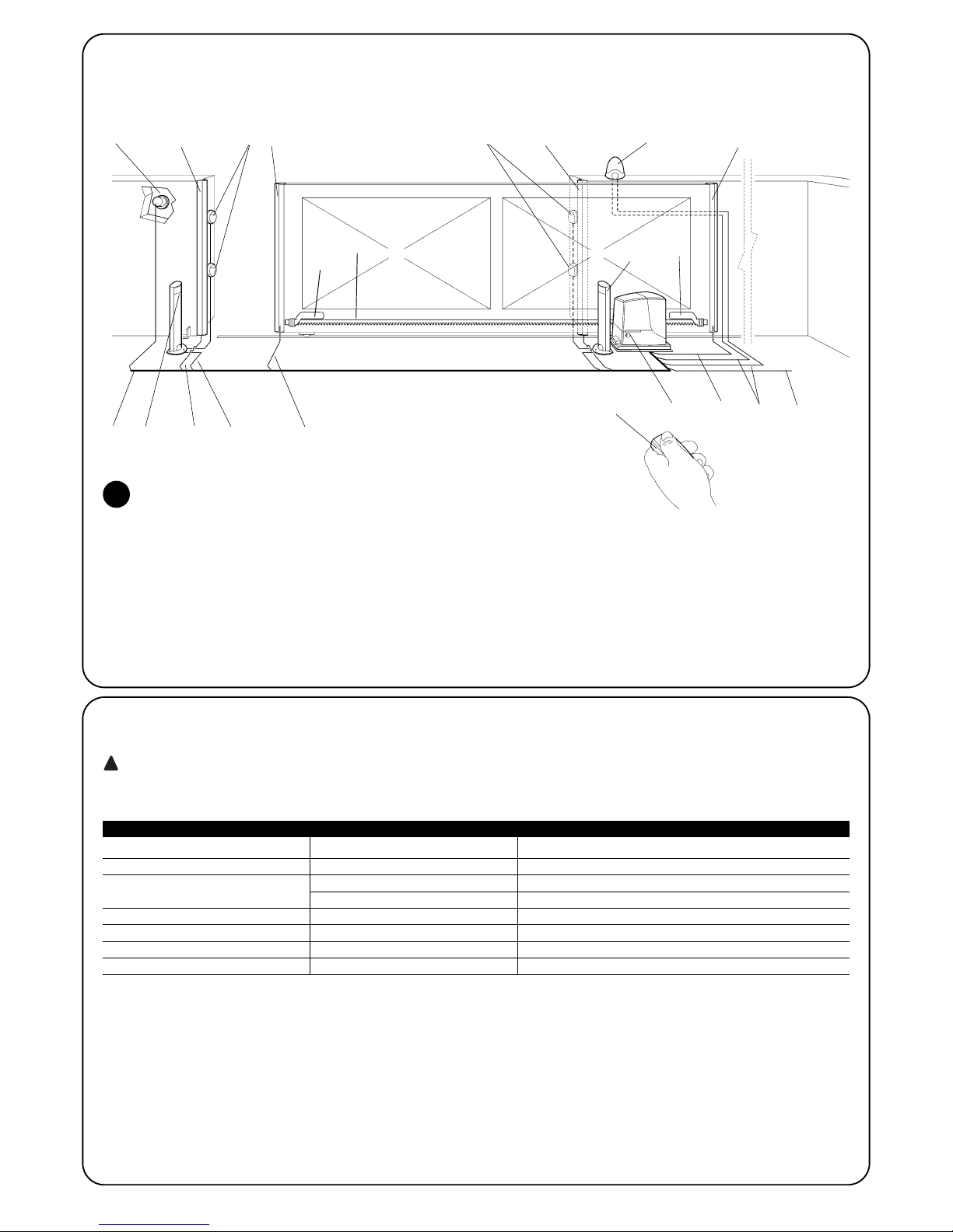
2.2) Typical system
Figure 2 shows a typical system for automating a sliding gate using ROBUS
2
1 Key-operated selector switch
2 Photocells on post
3 Photocells
4 Main fixed edge (optional)
5 Main movable edge
6 “Open” stop bracket
7 Rack
8 Secondary fixed edge (optional)
9 Flashing light with incorporated aerial
10 ROBUS
11 “Closed” stop bracket
12 Secondary movable edge (optional)
13 Radio-transmitter
2.3) List of cables
Figure 2 shows the cables needed for the connection of the devices in a typical installation; table 5 shows the cable characteristics.
The cables used must be suitable for the type of installation; for example, an H03VV-F type cable is recommended for indoor
applications, while H07RN-F is suitable for outdoor applications.
!
Note 1: power supply cable longer than 30 m may be used provided it has a larger gauge, e.g. 3x2,5mm2, and that a safety grounding sys-
tem is provided near the automation unit.
Note 2: If the “BLUEBUS” cable is longer than 30 m, up to 50 m, a 2x1mm
2
cable is needed.
Note 3: A single 2x0,5mm
2
cable can be used instead of two 4x0,5mm2cables.
Note 4: Please refer to Chapter “7.3.2 STOP Input” in situations where there is more than one edge, for information about the type of con-
nection recommended by the manufacturer.
Note 5: special devices which enable connection even when the leaf is moving must be used to connect movable edges to sliding leaves.
Connection Cable type Maximum length allowed
A: Power line 1 3x1,5mm2 cable 30m (note 1)
B: Flashing light with aerial 1 2x0,5mm2cable 20m
1 RG58 type shielded cable 20m (recommended less than 5 m)
C: Photocells 1 2x0,5mm2 cable 30m (note 2)
D: Key-operated selector switch 2 2x0,5mm2 cable (note 3) 50m
E: Fixed edges 1 2x0,5mm2 cable (note 4) 30m
F: Movable edges 1 2x0,5mm2 cable (note 4) 30m (note 5)
Table 5: List of cables
2
43 38
10
2
6
11
7
9
13
1251
EC F
D
C
F
A
B

7GB7
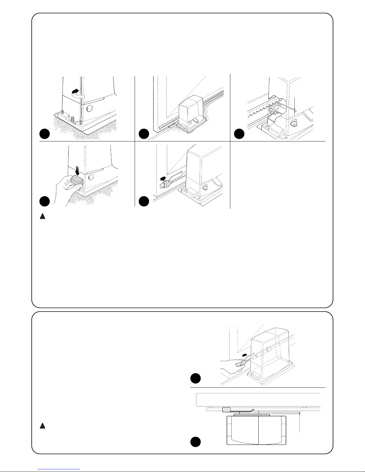
3.2) Installation of the gearmotor
The gearmotor must be fastened directly to an already existing
mounting surface using suitable means, for example expansion
screw anchors. Otherwise, in order to fasten the gearmotor the
installer must:
1. Dig a foundation hole with suitable dimensions referring to Figure 3.
2. Prepare one or more conduits for the electrical cables as shown
in figure 4.
3. Assemble the two clamps on the foundation plate setting one nut
underneath and one on top of the plate. The nut underneath the
plate must be as shown in Figure 5 screwed so that the thread-
ed part protrudes above the plate by approximately 25÷35 mm.
4. Pour the concrete and, before it starts to harden, set the foundation plate to the values shown in Figure 3. Check that it is parallel to the leaf and perfectly level (Figure 6). Wait for the concrete
to harden completely.
5. Remove the 2 upper nuts of the plate and then place the gearmotor onto them. Check that it is perfectly parallel to the leaf,
then screw the two nuts and washers supplied, as shown in Figure 7.
The installation of ROBUS must be carried out by qualified personnel in compliance with current legislation, standards and
regulations, and the directions provided in this manual.
!
3) Installation
3.1) Preliminary checks
Before proceeding with the installation of ROBUS you must:
•Check that all the materials are in excellent condition, suitable for
use and that they conform to the standards currently in force.
• Make sure that the structure of the gate is suitable for automation.
• Make sure that the weight and dimensions of the leaf fall within the
specified operating limits provided in chapter “2.1 Operating limits”.
• Check that the force required to start the movement of the leaf is
less than half the “maximum torque”, and that the force required to
keep the leaf in movement is less than half the “nominal torque”.
Compare the resulting values with those specified in Chapter “8
Technical Characteristics”. The manufacturers recommend a 50%
margin on the force, as unfavourable climatic conditions may
cause an increase in the friction.
• Make sure that there are no points of greater friction in the opening or closing travel of the gate leaves.
• Make sure there is no danger of the gate derailing.
• Make sure that the mechanical stops are sturdy enough and that
there is no risk of the deformation even when the leaf hits the
mechanical stop violently.
• Make sure that the gate is well balanced: it must not move by itself
when it is placed in any position.
•Make sure that the area where the gearmotor is fixed is not subject
to flooding. If necessary, mount the gearmotor raised from the
ground.
• Make sure that the installation area enables the release of the gearmotor and that it is safe and easy to release it.
• Make sure that the mounting positions of the various devices are
protected from impacts and that the mounting surfaces are sufficiently sturdy.
• Components must never be immersed in water or other liquids.
• Keep ROBUS away from heat sources and open flames; in acid,
saline or potentially explosive atmosphere; this could damage
ROBUS and cause malfunctions or dangerous situations.
• If there is an access door in the leaf, or within the range of movement of the gate, make sure that it does not obstruct normal travel. Mount a suitable interblock system if necessary.
• Only connect the control unit to a power supply line equipped with
a safety grounding system.
• The power supply line must be protected by suitable magnetothermal and differential switches.
• A disconnection device must be inserted in the power supply line
from the electrical mains (the distance between the contacts must
be at least 3.5 mm with an overvoltage category of III) or equivalent system, for example an outlet and relative plug. If the disconnection device for the power supply is not mounted near the
automation, it must have a locking system to prevent unintentional, unauthorised connection.
3
4
5
6
25÷35
7
192
330 0÷50
0÷50 330
192
0÷10
0÷10
3.3) Fixing of the limit switch bracket on versions with inductive limit switch
8
In order to prevent the weight of the leaf from affecting the
gearmotor, it is important that there is a play of 1÷2 mm between
the rack and the pinion as shown in Figure 10.
8.
Slide the leaf, using the pinion as a reference point for the fastening
the other elements of the rack.
9.
Cut away the exceeding part of the rack.
10.
Open and close the gate several times and make sure that the rack
is aligned with the pinion with a maximum tolerance of 5 mm. Moreover, check that the play of 1÷2 mm has been respected along the
entire length between the pinion and the rack.
11.
Thoroughly tighten the two fixing nuts of the gearmotor making sure
it is well fastened to the ground. Cover the fixing nuts with the relative caps as shown in figure 11.
12.
Fix the limit switch bracket as described below (for versions
RB600P and RB1000P, fix the bracket as described in paragraph
“3.3 Fixing of the limit switch bracket on versions with inductive limit switch”):
• Manually place the leaf in the open position leaving at least 2-3 cm
from the mechanical stop.
• Slide the bracket along the rack in the opening direction until the
limit switch cuts-in. Then bring the bracket forward by at least 2
cm and secure it to the rack with the appropriate dowels, as in fig.
12.
• Perform the same operation for the closure limit switch.
13. Lock the gearmotor as shown in “Release and manual movement”
paragraph in the Chapter “Instructions and Warnings for Users”
!
8 9 10
11 12
If the rack is already present, once the gearmotor has been fastened,
use the adjustment dowels as shown in Figure 8 to set the pinion of
ROBUS to the right height, leaving 1÷2 mm of play from the rack.
Otherwise, in order to fasten the rack the installer must:
6. Release the gearmotor as shown in “Release and manual movement” paragraph in the Chapter “Instructions and Warnings for
users of the ROBUS gearmotor”.
7. Open the leaf up completely and place the first piece of the rack
on the pinion. Check that the beginning of the rack corresponds
to the beginning of the leaf, as shown in Figure 9. Leave a 1÷2
mm play between the rack and the pinion, then fasten the rack to
the leaf using suitable means.
1÷2
The limit switch bracket must be fixed as described below for the
RB600P and RB1000P versions that utilise the inductive limit switch.
1. Manually place the leaf in the open position leaving at least
2-3 cm from the mechanical stop.
2. Slide the bracket along the rack in the opening direction until the
corresponding LED switches off, as in fig. 13. Then bring the
bracket forward by at least 2 cm and secure it to the rack with the
appropriate dowels.
3. Manually place the leaf in the closed position leaving at least 2-3
cm from the mechanical stop
4. Slide the bracket along the rack in the closing direction until the
corresponding LED switches off. Then bring the bracket forward
by at least 2 cm and secure it to the rack with the appropriate
dowels.
The ideal distance of the bracket for inductive limit switch-
es is between 3 and 8 mm as indicated in fig. 14.
!
13
14
3÷8

9
GB
3.5) Electrical connections
Only carry out electrical connections once the electricity supply to the system has been switched off. Disconnect any buffer batteries present.
1. Remove the protection cover in order to access the electronic control unit of
the ROBUS. The side screw must be removed, and the cover lifted upwards.
2. Remove the rubber membrane which closes the hole for passage of the
cables and insert all the connection cables towards the various devices,
leaving a length of 20÷30 cm longer than necessary. See Table 5 for information regarding the type of cables and Figure 2 for the connections.
3. Use a clamp to collect together and join the cables which enter the gear-
motor. Place the clamp just underneath the hole the cables enter
through.
Make a hole in the rubber membrane which is slightly smaller than the
diameter of the cables which have been collected together, and insert the
membrane along the cables until you reach the clamp. Then put the
membrane back in the slot of the hole the cables pass through. Lay a
second clamp for collecting the cables which are set just above the
membrane.
4. Connect the power cable to the appropriate terminal as shown in figure
15, then block the cable at the first cable block ring using the clamp.
5. Connect up the other cables according to the diagram in Figure 17. The
terminals can be removed in order to make this work easier.
6.
Once the connections have been completed, block the cables collected in the
second cable block ring using clamps. The excess of the aerial cable must be
blocked to the other cables using another clamp as shown in Figure 16.
!
3.4) Installation of the various devices
If other devices are needed, install them following the directions provided in the corresponding instructions. Check this in paragraph “3.6
Description of electrical connections” and the devices which can be connected to the ROBUS in Figure 2.
15
17
16
See paragraph “7.3.5 ROBUS in Slave mode” for the connection of 2 motors on opposite leaves.
LUCYB
S.C.A.
MOFB MOSE
OPEN CLOSE

10
3.6) Description of the electrical connections
The following is a brief description of the electrical connections; for
further information please read “7.3 Adding or Removing Devices”
paragraph.
FLASH: output for one or two “LUCYB” or similar type flashing
lights with single 12V maximum 21W bulb.
S.C.A.: “Open Gate Light” output. An indication lamp can be connected (24V max. 4W). It can also be programmed for other functions; see paragraph “7.2.3 Level two functions”.
BLUEBUS: compatible devices can be connected up to this terminal. They are connected in parallel using two conductors only,
through which both the electricity supply and the communication
signals travel. For more useful information about BlueBUS see also
Paragraph “7.3.1 BlueBUS”.
STOP: input for the devices which block or eventually stop the
manoeuvre in progress. Contacts like “Normally Closed”, “Normally
Open” or constant resistance devices can be connected up using
special procedures on the input. For more useful information about
STOP see also Paragraph “7.3.2 STOP Input”.
STEP-BY-STEP: input for devices which control Step-by-Step
movement. It is possible to connect “Normally Open” devices up to
this input.
OPEN: input for devices which control only the opening movement. It is possible to connect “Normally Open” devices up to this
input.
CLOSE: input for devices which control only the closing movement. It is possible to connect “Normally Open” devices up to this
input.
AERIAL: connection input for the radio receiver aerial (the aerial is
incorporated in LUCY B).
The manufacturers recommend you position the leaf at approximately half travel before starting the checking and start up phase of the
automation. This will ensure the leaf is free to move both during opening and closure.
4) Final checks and start up
4.1) Choosing the direction
The direction of the opening manoeuvre must be chosen depending
on the position of the gearmotor with respect to the leaf. If the leaf
must move left for opening, the selector must be moved towards left
as shown in Figure 18; alternatively, if the leaf has to move right during opening, the selector must be moved towards the right as shown
in Figure 19
18
19
4.2) Power supply connection
The connection of ROBUS to the mains must be made
by qualified and experienced personnel in possession of
the necessary requisites and in full respect of the laws,
provisions and standards currently in force.
As soon as ROBUS is energized, you should check the following:
1. Make sure that the “BLUEBUS” LED flashes regularly, with about
one flash per second.
2. Make sure that the LED’s on the photocells flash (both on TX and
RX); the type of flashing is not important as it depends on other
factors.
3. Make sure that the flashing light connected to the FLASH output
and the lamp LED connected to the “Open Gate Indicator” output are off.
If the above conditions are not satisfied, you should immediately
switch off the power supply to the control unit and check the electrical connections more carefully.
Please refer to Chapter “7.6 Troubleshooting” for further information
about finding and analysing failures.
!
4.3) Recognition of the devices
After connecting up the power supply, the control unit must be made to recognise the devices connected up to the BLUEBUS and STOP
inputs. Before this phase, LEDs L1 and L2 will flash to indicate that recognition of the devices must be carried out.
The connected devices recognition stage can be repeated at any time, even after the installation (for example, if a device is installed); for performing the new recognition see paragraph “7.3.6 Recognition of Other Devices”.
1. Press keys [▲] and [Set] and hold them down
2. Release the keys when L1 and L2 LED’s start flashing very quickly (after approx. 3 s)
3. Wait a few seconds for the control unit to finish recognizing the devices
4. When the recognition stage is completed the STOP LED must remain on while the
L1 and L2 LED’s must go off (LEDs L3 and L4 will eventually start flashing).
20

11
GB
4.4) Recognizing the length of the leaf
After recognizing the devices, L3 and L4 LED’s start flashing; the control unit must recognize the length of the gate. During this stage, the
length of the leaf is measured from the closing limit switch to the opening limit switch. This measurement is required to calculate the deceleration points and the partial opening point.
If the above conditions are not satisfied, you should immediately switch off the power supply to the control unit and check the electrical connections more carefully. For more useful information see also chapter “7.6 Troubleshooting”.
1. Press keys [▼] and [Set] and hold them down
2. Release the keys when the manoeuvre starts (after approx. 3 s)
3. Check the manoeuvre in progress is an opening manoeuvre. Otherwise, press the [Stop] key and
carefully check Paragraph “4.1 Choosing the Direction”, then repeat the process from Point 1.
4. Wait for the control unit to open the gate until it reaches the opening limit switch; the closing manoeuvre will
start immediately afterwards.
5. Wait for the control unit to close the gate.
4.5) Checking gate movements
On completion of the recognition of the length of the leaf, it is advisable to carry out a number of manoeuvres in order to check the gate
travels properly.
1. Press the [Open] key to open the gate. Check that gate opening
occurs regularly, without any variations in speed. The leaf must
only slowdown and stop when it is between 70 and 50 cm from
the opening mechanical stop. Then, at 2÷3 cm from the mechanical opening stop the limit switch will trigger.
2. Press the [Close] key to close the gate. Check that gate closing
occurs regularly, without any variations in speed. The leaf must
only slowdown and stop when it is between 70 and 50 cm from
the closing mechanical stop. Then, at 2÷3 cm from the mechanical closing stop the limit switch will trigger.
3. During the manoeuvre, check that the flashing light flashes at a
speed of 0.5 seconds on and 0.5 seconds off. If present, also
check the flashes of the light connected to the S.C.A. terminal:
slow flashes during opening, quick flashes during closing.
4.Open and close the gate several times to make sure that there are
no points of excessive friction and that there are no defects in the
assembly or adjustments.
5. Check that the fastening of the ROBUS gearmotor, the rack and
the limit switch brackets are solid, stable and suitably resistant,
even if the gate accelerates or decelerates sharply.
4.6) Preset functions
The ROBUS control unit has a number of programmable functions.
These functions are set to a configuration which should satisfy most
automations. However, the functions can be altered at any time by
means of a special programming procedure.
Please refer to paragraph “7.2 Programming” for further information
about this.
21
4.7) Radio receiver
The “SM” radio receiver connector for SMXI or SMXIS type optional radio receivers has been provided in order to enable the user to control
ROBUS from a distance. For further information consult the radio receiver instructions manual. The association between the radio receiver
output and the command performed by ROBUS is described in table 6:
22
Output N°1 STEP-BY-STEP command
Output N°2 “Partial opening” command
Output N°3 “Open” command
Output N°4 “Close” command
Table 6: commands with transmitter
This is the most important stage in the automation system installation procedure in order to ensure the maximum safety levels. Testing
can also be adopted as a method of periodically checking that all the
various devices in the system are functioning correctly.
Testing of the entire system must be performed by
qualified and experienced personnel who must establish
which tests to conduct on the basis of the risks involved,
and verify the compliance of the system with applicable
regulations, legislation and standards, in particular with
all the provisions of EN standard 12445 which establishes
the test methods for automation systems for gates.
!
5) Testing and commissioning
12
5.1) Testing
Each component of the system, e.g. safety edges, photocells, emergency stop, etc. requires a specific testing phase. We therefore recommend observing the procedures shown in the relative instruction
manuals. To test ROBUS proceed as follows:
1. Ensure that the instructions outlined in this manual and in particular in chapter 1 "WARNINGS" have been observed in full;
2. Release the gearmotor as shown in “Release and manual movement” paragraph in chapter “Instructions and Warnings for users
of the ROBUS gearmotor”
3. Make sure you can move the door manually both during opening
and closing with a force of max. 390N (40 kg approx.).
4. Lock the gearmotor.
5. Using the control or stop devices (key-operated selector switch,
control buttons or radio transmitter) test the opening, closing and
stopping of the gate and make sure that the leaves move in the
intended direction.
6. Check the proper operation of all the safety devices, one by one
(photocells, sensitive edges, emergency stop, etc.) and check
that the gate performs as it should. In particular, each time a
device is activated the “BlueBUS” LED on the control unit flashes
2 times quickly, confirming that the control unit recognizes the
event.
7. If the dangerous situations caused by the movement of the leaf
have been safeguarded by limiting the force of impact, the user
must measure the impact force according to EN Standard 12445.
If the adjustment of the “speed” and control of the “motor force”
are used to assist the system for the reduction of the impact
force, try to find the adjustment that gives the best results.
5.2) Commissioning
Commissioning can take place only after all the testing phases of the
ROBUS and the other devices have been terminated successfully. It
is not permissible to execute partial commissioning or to enable use
of the system in makeshift conditions.
1. Prepare and store for at least 10 years the technical documentation
for the automation, which must include at least: assembly drawing
of the automation, wiring diagram, analysis of hazards and solutions
adopted, manufacturer’s declaration of conformity of all the devices
installed (for ROBUS use the annexed CE declaration of conformity); copy of the instruction manual and maintenance schedule of the
automation.
2. Post a label on the gate providing at least the following data: type
of automation, name and address of manufacturer (person
responsible for the “commissioning”), serial number, year of manufacture and “CE” marking.
3. Post a permanent label or sign near the gate detailing the operations for the release and manual manoeuvre.
4. Prepare the declaration of conformity of the automation system
and deliver it to the owner.
5. Prepare the “Instructions and warnings for the use of the automation system” and deliver it to the owner.
6. Prepare the maintenance schedule of the automation system and
deliver it to the owner; it must provide all directions regarding the
maintenance of the single automation devices.
7. Before commissioning the automation system inform the owner in
writing regarding dangers and hazards that are still existing (e.g.
in the “Instructions and warnings for the use of the automation
system”).
This charter provides information about how to draw up a maintenance schedule, and the disposal of ROBUS
6) Maintenance and Disposal
6.1) Maintenance
The automation must be subjected to maintenance work on a regular basis, in order to guarantee it lasts; to this end ROBUS has a
manoeuvre counter and maintenance warning system; see paragraph “7.4.3 Maintenance warning”
The maintenance operations must be performed in
strict compliance with the safety directions provided in
this manual and according to the applicable legislation
and standards.
If other devices are present, follow the directions provided in the corresponding maintenance schedule.
1. ROBUS requires scheduled maintenance work every 6 months or
20,000 manoeuvres (max.) after previous maintenance:
2. Disconnect the power supply (and buffer batteries, if featured)
3. Check for any deterioration of the components which form the
automation, paying particular attention to erosion or oxidation of
the structural parts. Replace any parts which are below the
required standard.
4. Check the wear and tear on the moving parts: pinion, rack and
the leaf components; if necessary replace them.
5. Connect the electric power sources up again, and carry out the
testing and checks provided for in Paragraph “5.1 Testing”.
!
6.2) Disposal
ROBUS is constructed of various types of materials, some of which
can be recycled: steel, aluminium, plastic, electric cables; while others must be disposed of (batteries and electronic boards).
Some electronic components and the batteries may
contain polluting substances; do not pollute the environment. Enquire about the recycling or disposal systems
available in compliance regulations locally in force.
1. Disconnect the power supply of the automation system (and the buffer
battery, if featured).
2. Disassemble all the devices and accessories, following in reverse order
the procedures described in chapter 3 “Installation”.
3. Wherever possible, separate any parts which can or must be recycled
or disposed of in different ways, e.g. metal parts must be disposed of
separately from plastic ones, as must the electronic cards, batteries etc.
4. Sort the various materials and consign them to local licensed firms for
recovery and disposal.
!

13
GB
Programming, personalisation and how to look for and deal with faults on the ROBUS will be dealt with in this chapter.
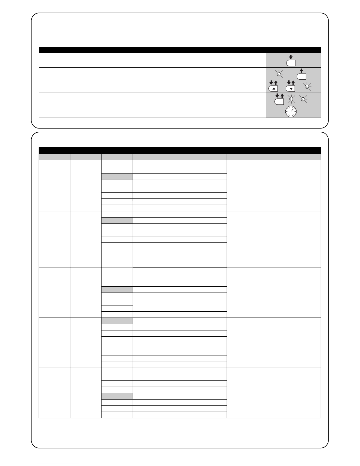
7) Additional information
Open The “OPEN” key enables the user to control the opening
▲ of the gate or move the programming point upwards.
Stop The “STOP” key enables the user to stop the manoeuvre. If pressed down
Set for more than 5 seconds it enables the user to enter programming.
Close The “CLOSE” key enables the user to control the closing of the gate or
▼ move the programming point downwards.
7.1) Programming keys
The ROBUS control unit feature three keys that can be used to command the control unit both during tests and programming.
23
7.2) Programming
A number of programmable functions are available on the ROBUS
control unit. The functions are adjusted using 3 keys set on the control unit: [▲] [Set] [▼] and are used by means of 8 LEDs: L1….L8.
The programmable functions available on ROBUS are set out on 2
levels:
Level one: the functions can be adjusted in modes ON-OFF (active
or inactive). In this case, each of the LEDs L1….L8 indicates a function. If the LED is on, the function is active, if off the function is inactive. See Table 7.
Level two: the parameters can be adjusted on a scale of values
(from 1 to 8). In this case, each of the LEDs L1…L8 indicates the
value set (there are 8 possible settings). Please refer to Table 9.
Led Function Description
L1 Automatic Closing This function causes the door to close automatically after the programmed time has lapsed. The factory
set Pause Time is 30 seconds, but can be changed to 5, 15, 30, 45, 60, 80, 120 or 180 seconds. If the
function is inactive, functioning will be “semi-automatic”.
L2 Close After Photo This function enables the gate to be kept open for the necessary transit time only. In fact the “Photo”
always causes an automatic closure with a pause time of 5s (regardless of the programmed value).
The action changes depending on whether the “Automatic closing” function is active or not.
When “Automatic Closing” is inactive: The gate always arrives to the totally open position (even if
the Photo disengages first). Automatic closing with a pause of 5s occurs when the Photo is disengaged.
When “Automatic Closing” is active: The opening manoeuvre stops immediately after the
photocells have disengaged. After 5 seconds, the gate will begin to close automatically.
The “Close after photo” function is always disabled in manoeuvres interrupted by a Stop command.
If the “Close after photo” function is inactive the pause time is that which has been programmed or there
is no automatic closing if the function is inactive.
L3 Always Close The “Always Close” function will trigger, and the gate will close if an open gate is detected when the
power supply returns. If the function is inactive when the power supply returns, the gate will remain still.
L4 Stand-By Stand-By This function enables the user to lower consumption to a very minimum. It is particularly
useful in cases when the buffer battery is being used. If this function is active, the control unit will switch
the BLUEBUS output (and consequently the devices) and all the LEDs off one minute after the end of the
manoeuvre. The only LED which will remain on is the BLUEBUS LED which will simply flash more slowly.
When a command arrives, the control unit will reset to complete functioning. If this function is inactive,
there will be no reduction in the consumption.
L5 Peak If this function is activated, the gradual acceleration at the beginning of each manoeuvre will be disconnected.
It enables the peak thrust and is useful whenever static friction is high, e.g. if snow or ice are blocking the
leaf.If the thrust is inactive, the manoeuvre will start with a gradual acceleration.
L6 Pre-flashing With the pre-flashing function, a 3 second pause is added between the flashing light switching on and
the beginning of the manoeuvre in order to warn the user, in advance, of a potentially dangerous
situation. If pre-flashing is inactive, the flashing light will switch on when the manoeuvre starts.
L7 “Close” becomes By activating this function all “close” commands (“CLOSE” input or radio command “close”)
“Open partially” activate a partial opening manoeuvre (see LED L6 on table 9).
L8 “Slave” mode By activating this function ROBUS becomes “Slave”: in this way it is possible to synchronise the
functioning of two motors on opposite leaves where one motor functions as Master and the other as
Slave; for further information see paragraph “7.3.5 ROBUS in “Slave” mode”.
During the normal functioning of the ROBUS, LEDs L1….L8 will either be on or off depending on the state of the function they represent.
For example, L1will be on if the “Automatic Closing” function is active.
Table 7: programmable function list: level one
7.2.1) Level one functions (ON-OFF functions).
14
Pause
Time
Step-by-step
Motor
speed
Open Gate Indicator Output
Motor
force
L1
L2
L3
L4
L5
L6
L7
L8
L1
L2
L3
L4
L5
L6
L7
L8
L1
L2
L3
L4
L5
L6
L7
L8
L1
L2
L3
L4
L5
L6
L7
L8
L1
L2
L3
L4
L5
L6
L7
L8
5 seconds
15 seconds
30 seconds
45 seconds
60 seconds
80 seconds
120 seconds
180 seconds
Open – stop – close - stop
Open – stop – close - open
Open – close – open - close
Condominium operation
Condominium operation 2 (more than 2” causes stop)
Step-by-Step 2 (less than 2” causes partial opening)Uomo presente
Man present
“Semiautomatic” opening,
“Man present ” closing
Very slow
Slow
Medium
Fast
Very fast
Extremely Fast
Opens “Fast”; closes “slow”
Opens “Extremely Fast” Closes “Fast”
Open Gate Indicator Function
On if leaf closed
On if leaf open
Active with 2nd radio output
Active with 3rd radio output
Active with 4th radio output
Maintenance indicator
Electric lock
Super light gate
“Very light” gate
“Light” gate
“Average” gate
“Average-heavy” gate
“Heavy” gate
“Very heavy” gate
“Super heavy” gate
7.2.2) Level one programming (ON-OFF functions).
Level 1 functions are all factory set to “OFF”. However, they can be changed at any time as shown in Table 8. Follow the procedure carefully, as there is a maximum time of 10 seconds between pressing one key and another. If a longer period of time lapses, the procedure will finish automatically and memorize the modifications made up to that stage.
1. Press the key [Set] and hold it down (approx. 3 s)
3s
2. Release the [Set] key when L1 LED starts flashing
L1
3. Press keys [▲] or [▼] to move the flashing LED onto the LED representing
the function which is to be changed or
4. Press the [Set] key to change the state of the
function (short flashing = OFF; long flashing = ON)
5. Wait 10 seconds before leaving the programme to allow the maximum time to lapse.
10s
Note: Points 3 and 4 can be repeated during the same programming phases in order to set other functions to ON or OFF
Table 8: changing ON-OFF functions Example
SET
SET
SET
7.2.3 Level two functions (adjustable parameters)
Table 9: programmable function list: level two
Input LED
Parameter LED (level) value Description
Adjusts the pause time, namely the time
which lapses before automatic closure.
This will only have an effect if automatic
closing is active.
Manages the sequence of controls associated to the Step-by-Step input or to the
1st radio command.
Adjusts the speed of the motor during normal travel.
Adjusts the function associated with the
S.C.A. output (whatever the associated
function may be, the output supplies a voltage of 24V –30 +50% with a maximum
power of 4W when active).
Adjusts the system which controls the
motor force in order to adapt it to the
weight of the gate. The force control system also measures the ambient temperature, automatically increasing the force in
the event of particularly low temperatures.
L1
L2
L3
L4
L5

15
GB
Note: “ ” represents the factory setting
All the parameters can be adjusted as required without any contraindication; only the adjustment of the “motor force” could require special
care:
• Do not use high force values to compensate for points of abnormal friction on the leaf. Excessive force can compromise the operation of
the safety system or damage the leaf.
• If the “motor force” control is used to assist the impact force reduction system, measure the force again after each adjustment in compli-
ance with EN standard 12445.
• Wear and weather conditions may affect the movement of the gate, therefore periodic force re-adjustments may be necessary.
Open Partially
Maintenance
warning
List of
malfunctions
L1
L2
L3
L4
L5
L6
L7
L8
L1
L2
L3
L4
L5
L6
L7
L8
L1
L2
L3
L4
L5
L6
L7
L8
0,5 m
1 m
1,5 m
2 m
2,5 m
3 m
3,4 m
4 m
Automatic (depending on the severity of the
manoeuvre)
1000
2000
4000
7000
10000
15000
20000
1amanoeuvre result
2amanoeuvre result
3amanoeuvre result
4amanoeuvre result
5amanoeuvre result
6amanoeuvre result
7amanoeuvre result
8
a
manoeuvre result
Led di entrata
Parametro Led (livello) Valore Descrizione
Adjusts the measurement of the partial
opening. Partial opening can be controlled
with the 2nd radio command or with
“CLOSE”, if the “Close” function is present,
this becomes “Open partially”.
Adjusts the number of manoeuvres after
which it signals the maintenance request of
the automation (see paragraph “7.4.3
Maintenance warning”).
The type of defect that has occurred in the
last 8 manoeuvres can be established (see
paragraph “7.6.1 Malfunctions archive”).
L6
L7
L8
7.2.4) Level two programming (adjustable parameters)
The adjustable parameters are factory set as shown in the table 9, with: “ ” However, they can be changed at any time as shown in Table
10. Follow the procedure carefully, as there is a maximum time of 10 seconds between pressing one key and another. If a longer period of
time lapses, the procedure will finish automatically and memorize the modifications made up to that stage.
1. Press the key [Set] and hold it down (approx. 3 s
3s
2. Release the [Set] key when L1 LED starts flashing
L1
3. Press key [▲] or [▼] to move the flashing LED onto the input LED representing the
parameter which is to be changed or
4. Press the key [Set], and hold it down during step 5 and 6
5. Wait approx. 3 seconds, after which the LED representing the current
level of the parameter which is to be modified will light up.
6. Press key [▲] or [▼] to move the LED representing the parameter value.
or
7. Release the key [Set]
8. Wait 10 seconds before leaving the programme to allow the maximum time to lapse.
10s
Note: Points 3 to 7 can be repeated during the same programming phase in order to set other parameters
Table 10: changing the adjustable parameters Example
SET
SET
SET
SET

16
7.2.6) Level two programming example (adjustable parameters)
The sequence to follow in order to change the factory settings of the parameters increasing the “Pause Time” to 60 seconds (input on L1
and level on L5) and reducing the “Motor Force” for light gates (input on L5 and level on L2) have been included as examples
1. Press the key [Set] and hold it down (approx. 3 s)
3s
2. Release the [Set] key when L1 LED starts flashing
L1
3. Press the key [Set] and hold it down during step 4 and 5
4. Wait approx. 3 seconds until LED L3, representing the current level
of the “Pause Time” will light up L3 3s
5. Press the [▼] key twice to move the LED which is lit to LED L5,
which represents the new “Pause Time” value L5
6. Release the key [Set]
7. Press the [▼] key four times to move the flashing LED to LED L5
L5
8. Press the key [Set]; and hold it down during step 9 and 10
9. Wait approx. 3 seconds until LED L5, representing the current
level of the “Motor Force” will light up 3s L5
10. Press the [▲] key three times to move the LED which is lit to LED L2,
which represents the new “Motor Force” value L2
11. Release the key [Set]
12. Wait 10 seconds before leaving the programme to allow the maximum time to lapse.
10s
Table 12: Level two programming example Example
SET
SET
SET
SET
SET
SET
7.3) Adding or removing devices
Devices can be added to or removed from the ROBUS automation
system at any time. In particular, various devices types can be connected to “BlueBUS” and “STOP” input as explained in the following
paragraphs.
After you have added or removed any devices, the
automation system must go through the recognition
process again according to the directions contained in
paragraph 7.3.6 “Recognition of other devices”.
7.3.1) BlueBUS
BlueBUS technology allows you to connect compatible devices
using only two wires which carry both the power supply and the
communication signals. All the devices are connected in parallel on
the 2 wires of the BlueBUS itself. It is not necessary to observe any
polarity; each device is individually recognized because a univocal
address is assigned to it during the installation. Photocells, safety
devices, control keys, signalling lights etc. can be connected to
BlueBUS. The ROBUS control unit recognizes all the connected
devices individually through a suitable recognition process, and can
detect all the possible abnormalities with absolute precision. For this
reason, each time a device connected to BlueBUS is added or
removed the control unit must go through the recognition process;
see paragraph 7.3.6 “Recognition of Other Devices”.
7.2.5) Level one programming example (ON-OFF functions).
The sequence to follow in order to change the factory settings of the functions for activating “Automatic Closing” (L1) and “Always close” (L3)
have been included as examples.
1. Press the key [Set] and hold it down (approx. 3 s)
3s
2. Release the [Set] key when L1 LED starts flashing
L1
3. Press the [Set] key once to change the state of the function associated with L1
Automatic Closing). LED L1 will now flash with long flashes. L1
4. Press the [▼] key twice to move the flashing LED to LED L3
L3
5. Press the [Set] key once to change the state of the function associated with L3
(Always Close). LED L3 will now flash with long flashes. L3
6. Wait 10 seconds before leaving the programme to allow the maximum time to lapse.
10s
Once these operations have been completed, LEDs L1 and L3 must remain on to indicate that the “Automatic Closing” and the “Always
Close” functions are active.
Tabella 11: Level one programming example Example
SET
SET
SET
SET

17
GB
7.3.2) STOP input
STOP is the input that causes the immediate interruption of the
manoeuvre (with a short reverse run). Devices with output featuring
normally open “NO” contacts and devices with normally closed “NC”
contacts, as well as devices with 8,2KΩ, constant resistance output,
like sensitive edges, can be connected to this input.
During the recognition stage the control unit, like BlueBUS, recognizes the type of device connected to the STOP input (see paragraph 7.3.6 “Recognition of Other Devices”); subsequently it commands a STOP whenever a change occurs in the recognized status.
Multiple devices, even of different type, can be connected to the
STOP input if suitable arrangements are made.
• Any number of NO devices can be connected to each other in
parallel.
• Any number of NC devices can be connected to each other in
series.
• Two devices with 8,2KΩ constant resistance output can be connected in parallel; if needed, multiple devices must be connected
“in cascade” with a single 8,2KΩ.
• It is possible to combine Normally Open and Normally Closed by
making 2 contacts in parallel with the warning to place an 8,2KΩ
resistance in series with the Normally Closed contact (this also
makes it possible to combine 3 devices: Normally Open, Normally Closed and 8,2KΩ).
If the STOP input is used to connect devices with safety functions, only the devices with 8,2KΩ constant resistance output guarantee the fail-safe category 3 according
to EN standard 954-1.
!
FOTO
External photocell h = 50
activated when gate closes
FOTO II
External photocell h = 100
activated when gate closes
FOTO 1
External photocell h = 50
activated when gate closes
FOTO 1 II
Internal photocell h = 100
activated when gate closes
FOTO 2
External photocell
activated when gate opens
FOTO 2 II
Internal photocell
when gate opens
FOTO 3
Single photocell for the
entire automation system
in the case of the installation of FOTO 3 and FOTO II together
the position of the photocell elements (TX-RX) must comply with the
provisions contained in the photocell instruction manual.
!
7.3.3) Photocells
By means of addressing using special jumpers, the “BlueBUS” system enables the user to make the control unit recognise the photocells and assign them with a correct detection function. The
addressing operation must be done both on TX and RX (setting the
jumpers in the same way) making sure there are no other couples of
photocells with the same address.
In an automation for sliding gates, with ROBUS it is possible to install
the photocells as shown in Figure 24.
Each time a photocell is added or removed the control unit must go
through the recognition process; see paragraph 7.3.6 “Recognition
of Other Devices”.
7.3.4) FT210B Photo-sensor
The FT210B photo-sensor unites in a single device a force limiting
device (type C in accordance with the EN1245 standard) and a presence detector which detects the presence of obstacles on an optical axis between the TX transmitter and the RX receiver (type D in
accordance with the EN12453 standard). The sensitive edge status
signals on the FT210 photo-sensor are transmitted by means of the
photocell beam, integrating the two systems in a single device. The
transmitting part is positioned on the mobile leaf and is powered by
a battery thereby eliminating unsightly connection systems; the consumption of the battery is reduced by special circuits guaranteeing a
duration of up to 15 years (see the estimation details in the product
instructions).
By combining a FT210B device to a sensitive edge (TCB65 for
example) the level of security of the “main edge”, required by the
EN12453 standard for all “types of use” and “types of activation”,
can be attained. The FT210B is safe against individual faults when
combined to a “resistive” type (8,2Kohm) sensitive edge. It features
a special anticollision circuit that prevents interference with other
detectors, even if not synchronised, and allows additional photocells
to be fitted; for example, in cases where there is a passage of heavy
vehicles and a second photocell is normally placed at 1 m from the
ground.
See the FT210B instructions manual for further information concerning connection and addressing methods.
24
Tabelle 13: Photocell addressing
Photocell Jumpers Photocell Jumpers

18
7.3.5) ROBUS in “Slave” mode
Properly programming and connecting, ROBUS can function in
“Slave” mode; this type of function is used when 2 opposite gates
need to be automated with the synchronised movement of the two
leaves. In this mode ROBUS works as Master commanding the
movement, while the second ROBUS acts as Slave, following the
commands transmitted by the Master (all ROBUS are Masters when
leaving the factory).
To configure ROBUS as a Slave the level one “Slave mode” must be
activated (see table 7).
The connection between ROBUS Master and ROBUS Slave is made
via BlueBus.
In this case the polarity of the connections between
the two ROBUS must be respected as illustrated in fig. 26
(the other devices remain with no polarity).
Follow the operations below to install 2 ROBUS in the Master and
Slave mode:
• Install the 2 motors as indicated in fig. 25. It is not important which
motor is to function as Slave or Master; when choosing, one must
consider the convenience of the connections and the fact that the
Step-by-Step command of the Slave only allows the Slave leaf to
be opened fully.
• Connect the 2 motors as shown in fig. 26.
• Select the opening direction of the 2 motors as shown in fig. 25
(see also paragraph “4.1 Choosing the direction”).
• Supply power to the 2 motors.
• Program the “Slave mode” on the ROBUS Slave (see table 7).
• Perform the device recognition on the ROBUS Slave (see paragraph “4.3 Recognition of the devices”).
• Perform the device recognition on the ROBUS Master (see paragraph “4.3 Recognition of the devices”).
• Perform the recognition of the leaf length on the ROBUS Master
(see paragraph “4.4 Recognition length of the leaf”).
!
25
26
When connecting 2 ROBUS in the Master-Slave mode, pay attention that:
• All devices must be connected to the ROBUS Master (as in fig. 26) including the radio receiver.
• When using buffer batteries, each motor must have its own battery.
• All programming performed on ROBUS Slave are ignored (those on ROBUS Master override the others) except for those mentioned in table 14.
LUCYB
S.C.A.
MOFB
MOSE
OPEN
CLOSE
LUCYB
S.C.A.
STOP
PP

19
GB
7.4.1) “Always open” Function
The “Always open” function is a control unit feature which enables the
user to control an opening manoeuvre when the “Step-by-Step” command lasts longer than 2 seconds. This is useful for connecting a timer
contact to the “Step-by-Step” terminal in order to keep the gate open for
a certain length of time, for example. This feature is valid with any kind of
“Step-by-Step” input programming, except for “Close”. Please refer to
the “Step-by-Step Function” parameter in Table 9.
7.4.2) Move anyway” function
In the event that one of the safety devices is not functioning properly or is out of use, it is still possible to command and move the gate
in “Man present” mode.
Please refer to the Paragraph “Control with safety devices out of
order” in the enclosure “Instructions and Warnings for users of the
ROBUS gearmotor” for further information.
7.4.3) Maintenance warning
With ROBUS the user is warned when the automation requires a maintenance control. The number of manoeuvres after the warning can be selected from 8 levels, by means of the “Maintenance warning” adjustable parameter (see table 9).
Adjustment level 1 is “automatic” and takes into consideration the severity
of the manoeuvre, this being the force and duration of the manoeuvre, while
the other adjustments are established based on the number of manoeuvres.
The maintenance request signal is given by means of the flashing light
(Flash) or by the light connected to the S.C.A. output when programmed as a “Maintenance light” (see table 9). The flashing light
“Flash” and the maintenance light give the signals indicated in table
16, based on the number of manoeuvres performed in respect to the
limits that have been programmed.
7.4) Special functions
Tabella 14: ROBUS Slave programming independent from ROBUS Master
Level one functions (ON-OFF functions) Level two functions (adjustable parameters)
Stand-by Motor speed
Peak Open Gate Indicator Output
Slave Mode Motor force
Error list
On Slave it is possible to connect:
•
A flashing light (Flash)
•
An open gate light (S.C.A.)
•
A sensitive edge (Stop)
•
A command device (Step by Step) that controls the complete opening of the Slave leaf only.
•
The Open and Close inputs are not used on the Slave
7.3.6) Recognition of Other Devices
Normally the recognition of the devices connected to the BlueBUS and the STOP input takes place during the installation stage. However, if new
devices are added or old ones removed, the recognition process can be gone through again by proceeding as shown in Figure 15.
1. Press keys [▲] and [Set] and hold them down
2. Release the keys when L1 and L2 LED’s start flashing very quickly (after approx. 3 s)
L1 L2
3. Wait a few seconds for the control unit to finish recognizing the devices
4. When the recognition stage is completed L1 and L2 LED’s will go off, the STOP LED must remain on,
while L1…L8 LED’s will light up according to the status of the relative ON-OFF functions L1 L2
After you have added or removed any devices, the automation system must be tested again according to the directions
contained in paragraph 5.1 “Testing”.
!
Tabella 15: Recognition of Other Devices Example
SET
SET
Number of manoeuvres Flash signal Maintenance light signal
Lower than 80% of the limit
Between 81 and 100% of the limit
Over 100% of the limit
Normal (0.5s on, 0.5s off)
Remains on for 2s at the beginning of the
manoeuvre then carries on normally
Remains ON for 2s at the start and end of
the manoeuvre then carries on normally
On for 2s when opening begins
Flashes throughout the manoeuvre
Always flashes .
Tabella 16: maintenance warning with Flash and maintenance light

1. Press the key [Set] and hold it down (approx. 3 s)
3s
2. Release the [Set] key when L1 LED starts flashing
L1
3. Press key [▲] or [▼] to move the flashing LED onto the input LED L7
representing the “Maintenance warning” parameter or L7
4. Press the key [Set],and hold it down during step 5, 6 and 7
5. Wait approx. 3 seconds, after which the LED representing the current
level of the parameter “Maintenance warning” will light up 3s
6. Press and immediately release the [▲] and [▼] keys.
and
7. The LED that corresponds to the selected level flashes. The number of flashes indicates the percentage
of manoeuvres performed(in multiples of 10%) in relation to the set limit.
For example: with the maintenance warning set on L6 being 10000, 10% is equal to 1000 manoeuvres;
if the LED flashes 4 times, this means that 40% of the manoeuvres have been reached (being between
4000 and 4999 manoeuvres). The LED will not flash if 10% of the manoeuvres hasn’t been reached.
8. Release the key [Set]
20
Control of the number of manoeuvres performed
The number of manoeuvres performed as a percentage on the set limit can be verified by means of the “Maintenance warning” function. Follow the indications in table 17 for this control.
Tabella 17: control of the number of manoeuvres performed Example
SET
SET
SET
SET
.... n=?
Manoeuvre counter reset
After the maintenance of the system has been performed the manoeuvre counter must be reset. Proceed as described in table 18.
1. Press the key [Set] and hold it down (approx. 3 s)
3s
2. Release the [Set] key when L1 LED starts flashing
L1
3. Press key [▲] or [▼] to move the flashing LED onto the input LED L7 representing the
“Maintenance warning” parameter or L7
4. Press the key [Set], and hold it down during step 5 and 6
5. Wait approx. 3 seconds, after which the LED representing the current
level of the parameter “Maintenance warning” will light up. 3s
6. Press keys [▲] and [▼], hold them down for at least 5 seconds and then release them.
The LED that corresponds to the selected level flashes rapidly indicating that the
manoeuvre counter has been reset
and
7. Release the key [Set]
Table 18: manoeuvre counter reset Example
SET
SET
SET
SET
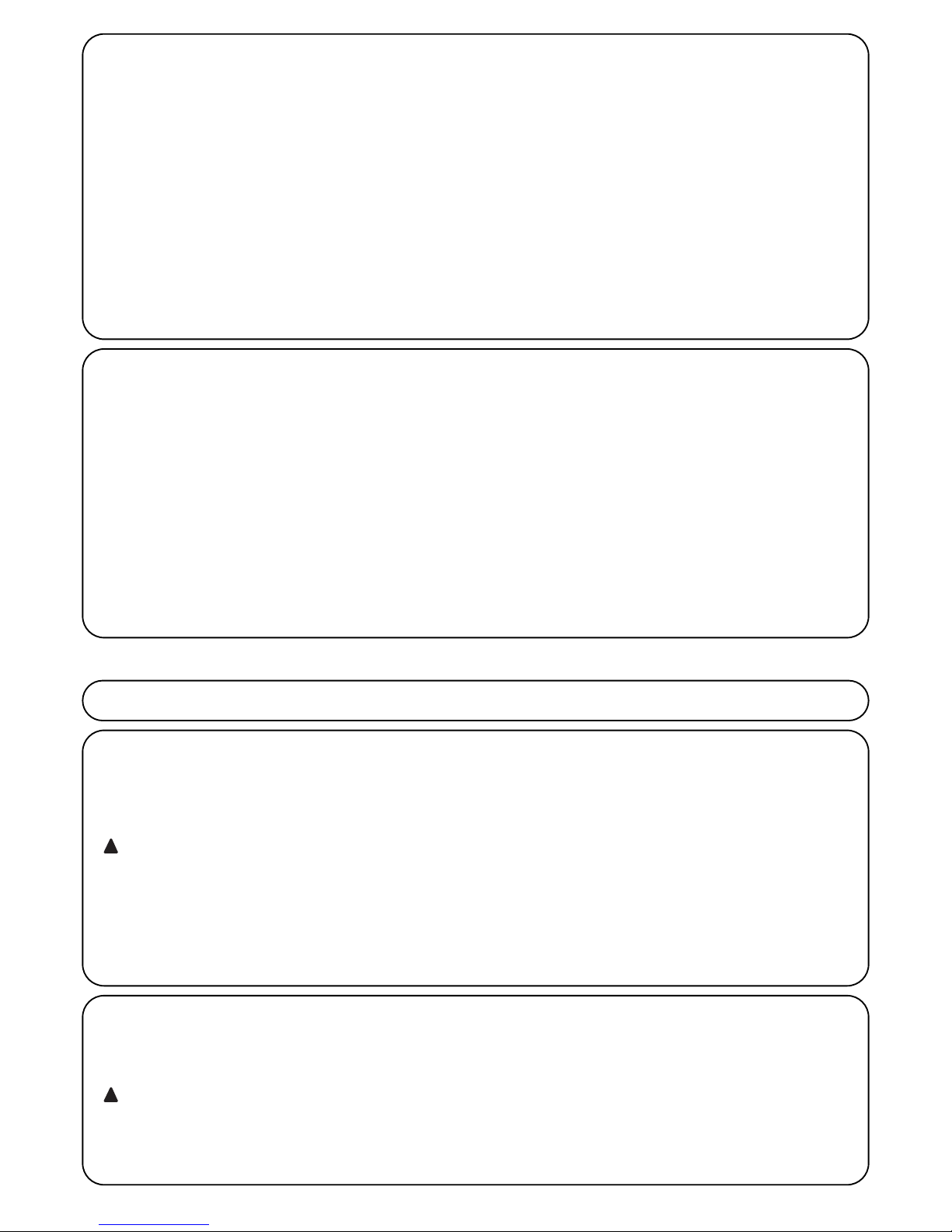
7.5 Connection of Other Devices
If the user needs to feed external devices such as a proximity reader for transponder cards or the illumination light of the key-operated
selector switch, it is possible to tap power as shown in Figure 27.
The power supply voltage is 24Vdc -30% - +50% with a maximum
available current of 100mA.
-+
24Vcc
27

21
GB
7.7) Diagnostics and signals
A few devices issue special signals that allow you to recognize the
operating status or possible malfunctions.
7.6) Troubleshooting
The table 19 contains instructions to help you solve malfunctions or
errors that may occur during the installation stage or in case of failure.
29
Tabella 19: Troubleshooting
Symptoms Recommended checks
The radio transmitter does not control the gate
and the LED on the transmitter does not light up
The radio transmitter does not control the gate
but the LED on the transmitter lights up
No manoeuvre starts and the “BlueBUS” LED
does not flash
No manoeuvre starts and the flashing light is off
No manoeuvre starts and the flashing light flashes a few times
The manoeuvre starts but it is immediately followed by a reverse run
The manoeuvre is carried out but the flashing
light does not work
The manoeuvre is carried out but the Open
Gate Indicator does not work
Check to see if the transmitter batteries are exhausted, if necessary replace them
Check to see if the transmitter has been memorised correctly in the radio receiver
Check that ROBUS is powered by a 230V mains supply.
Check to see if the fuses are blown; if necessary, identify the reason for the failure and
then replace the fuses with others having the same current rating and characteristics.
Make sure that the command is actually received. If the command reaches the STEPBY-STEP input, the corresponding “STEP-BY-STEP” LED must light up; if you are
using the radio transmitter, the “BlueBus” LED must make two quick flashes.
Count the flashes and check the corresponding value in table 21
The selected force could be too low for this type of gate. Check to see whether there
are any obstacles; if necessary increase the force
Make sure that there is voltage on the flashing light’s FLASH terminal during the
manoeuvre (being intermittent, the voltage value is not important: approximately 1030Vdc); if there is voltage, the problem is due to the lamp; in this case replace the
lamp with one having the same characteristics; if there is no voltage, there may have
been an overload on the FLASH output. Check that the cable has not short-circuited.
Check the type of function programmed for the S.C.A. output (Table 9)
When the light should be on, check there is voltage on the S.C.A. terminal (approximately
24Vdc). If there is voltage, then the problem will have been caused by the light, which will have
to be replaced with one with the same characteristics. If there is no voltage, there may have
been an overload on the S.C.A. output. Check that the cable has not short-circuited.
F2
F1
1. Press the key [Set] (approx. 3 s)
3s
2. Release the [Set] key when L1 LED starts flashing
L1
3. Press key [▲] or [▼] to move the flashing LED onto the input LED
L8 representing the “malfunctions list” parameter or L8
4. Press the key [Set], and hold it down during step 5 and 6
5. Wait for about 3s after which the LEDs corresponding to the manoeuvres in which the
defect occurred will light. The L1 LED indicates the result of the last manoeuvre
and L8 indicates the result of the 8th manoeuvre. If the LED is on, this means that a defect occurred
during that manoeuvre; if the LED is off, this means that no defect occurred during that manoeuvre.
6. Press keys [▲] and [▼] to select the required manoeuvre:
The corresponding LED flashes the same number of times as those made by the
flashing light after a defect (see table 21).
and
7. Release the key [Set]
Table 20: malfunctions archive Example
SET
SET
SET
SET
7.6.1) Malfunctions archive
ROBUS allows the possible malfunctions that have occurred in the last 8 manoeuvres to be viewed; for example, the interruption of a
manoeuvre due to a photocell or sensitive edge cutting in. To verify the malfunctions list, proceed as in table 20.
3s

22
BLUEBUS LED Cause ACTION
STOP LED Cause ACTION
STEP-BY-STEP LED Cause ACTION
OPEN LED Cause ACTION
Off
ACTION
7.7.2) Signals on the control unit
On the ROBUS350 control unit there is a set of LED's each of which can give special indications both during normal operation and in
case of malfunctions.
Tabella 22: LED’s on the control unit’s terminals
Malfunction
Make sure there is power supply; check to see if the fuses are blown; if necessary, identify the reason for the failure and then replace the fuses with others having the same characteristics replaced
On Serious malfunction
There is a serious malfunction; try switching off the control unit for a few seconds; if the condition persists it means there is a malfunction and the electronic board has to be replaced
One flash every second Everything OK Normal operation of control unit
2 quick flashes
The status of the inputs has
changed
This is normal when there is a change in one of the inputs: STEP-BY-STEP,
STOP, OPEN, CLOSE, triggering of photocells or the radio transmitter is used
Series of flashes separated by a
second's pause
Miscellaneous It corresponds to the flashing light's signal. See table n° 21.
Off
ACTION
Activation of the STOP input Check the devices connected to the STOP input
On Everything OK STOP Input active
Off Everything OK input not active
On
Off
Activation of the STEP-BY-STEP input
Everything OK
This is normal if the device connected to the STEP-BY-STEP input is actually active
OPEN input not active
On
Activation of the OPEN input
This is normal if the device connected to the OPEN input is actually active
CLOSE LED Cause ACTION
Off Everything OK CLOSE input not active
On
Activation of the CLOSE input
This is normal if the device connected to the CLOSE input is actually active
29
6 flashes
1 second’s pause
6 flashes
At the starting of the manoeuvre, the devices connected to BLUEBUS do not
correspond to those recognized during the recognition phase. One or more
devices may be faulty; check and, if necessary, replace them; in case of modifications repeat the recognition process (7.3.4 Recognition of Other Devices).
7.7.1) Flashing light signalling
During the manoeuvre the flashing light FLASH flashes once every second. When something is wrong the flashes are more frequent; the light
flashes twice with a second's pause between flashes.
Tabella N°21: FLASH flashing light signalling
Quick flashes Cause ACTION
1 flash
1 second’s pause
1 flash
BlueBUS error
2 flashes
1 second’s pause
2 flashes
Triggering of a photocell
At the starting of the manoeuvre, one or more photocells do not enable it;
check to see if there are any obstacles.
This is normal when there is an obstacle impeding the movement.
3 flashes
1 second’s pause
3 flashes
Activation of the “motor force” limiting device
During the movement, the gate experienced excessive friction; identify the
cause.
4 flashes
1 second’s pause
4 flashes
Activation of the STOP input
At the starting of the manoeuvre or during the movement, the STOP input was
activated; identify the cause
5 flashes
1 second’s pause
5 lampeggi
Error in the internal parameters of the electronic control
unit
Wait at least 30 seconds, then try giving a command. if the condition persists it
means there is a malfunction and the electronic board has to be replaced
The maximum manoeuvre
limit/hour has been exceeded.
Wait for a few minutes until the manoeuvre limiting device drops to under the
maximum limit
7 flashes
1 second’s pause
7 flashes
8 flashes
1 second’s pause
8 flashes
here is an error in the internal electric circuits
A command that does not
permit other commands to be
performed is already present.
Disconnect all the power circuits for a few seconds and then try to give the
command again. if the condition persists it means there is a serious malfunction and the electronic board has to be replaced
Check the type of command that is always present; for example, it could be a
command from a timer on the “open” input.

23
GB
7.8) Accessories
The following optional accessories are available for ROBUS:
• PS124 PS124 24 V Buffer battery - 1,2Ah with integrated charger
battery.
• SMXI or SMXIS 433.92MHz Radio receiver with digital Rolling code.
For information on the complete range of accessories, refer to the
Nice s.p.a. product catalogue.
30
Led 1 Description
• Function programming in progress.
• If it flashes together with L4, it means that the user must carry out the leaf length recognition phase
(refer to Paragraph “4.4 Recognition length of the leaf”).
Led L6 Description
Led L5 Description
Led L3 Description
Led L2 Description
Led L4
Description
During normal operation the device indicates “Thrust” is not active.Off
Off
Tabella 23: LED’s on the control unit’s keys
During normal operation the device indicates “Automatic Closing” is not active
During normal operation the device indicates “Automatic Closing” is active.
• Function programming in progress.
• If it flashes together with L2, it means that the user must carry out the device recognition phase (refer to
Paragraph “4.3 Recognition of the devices”).
on
It flashes
Off During normal operation the device indicates “Close after photo” is not active.
During normal operation the device indicates “Close after photo” is active.
• Function programming in progress.
• If it flashes together with L1, it means that the user must carry out the device recognition phase (refer to
Paragraph “4.3 Recognition of the devices”).
on
It flashes
Off During normal operation the device indicates “Always close” is not active.
During normal operation the device indicates “Always close” is active.
During normal operation the device indicates “Stand-by” is not active.
During normal operation the device indicates “Stand-by” is active.
• Function programming in progress.
• If it flashes together with L3, it means that the user must carry out the leaf length recognition phase
(refer to Paragraph “4.4 Recognition length of the leaf”).
on
It flashes
Off
on
It flashes
During normal operation the device indicates “Thrust” is active.
Function programming in progress.
on
It flashes
During normal operation the device indicates “Pre-flashing” is not active.
During normal operation the device indicates “Pre-flashing” is active.
Function programming in progress.
Off
on
It flashes
Led L7 Description
During normal operation the device indicates that the CLOSE input activates a closing manoeuvre.
During normal operation the device indicates that the CLOSE input activates a partial opening manoeuvre.
Function programming in progress.
Off
on
It flashes
Led L8 Description
During normal operation the device indicates that ROBUS is configured as Master.
During normal operation the device indicates that ROBUS is configured as Slave.
Function programming in progress.
Off
on
It flashes
31

Use in acid, saline or potentially explosive
atmosphere
330 x 210 h 303; 11Kg 330 x 210 h 303; 13Kg
Nice S.p.a., in order to improve its products, reserves the right to modify their technical characteristics at any time without prior notice. In
any case, the manufacturer guarantees their functionality and fitness for the intended purposes.
All the technical characteristics refer to an ambient temperature of 20°C (±5°C)
8) Technical characteristics
Type
Model
Technical characteristics: ROBUS
Electromechanical gearmotor for the automatic movement of sliding gates for residential
use, complete with electronic control unit
RB600 – RB600P RB1000 – RB1000P
Pinion Z: 15; Module: 4; Pitch: 12.6 mm; Pitch diameter: 60mm
Peak thrust
[corresponding to the ability to develope a
force capable of moving the leaf]
18Nm
[600N]
27Nm
[900N]
Nominal torque
[corresponding to the ability to develope a force
capable of maintaining the movement of the leaf]
9Nm
[300N]
15Nm
[500N]
Nominal torque speed
0,15m/s 0,14m/s
Idling speed (the control unit allows 6 speeds
to be programmed, approx. equal to: 100, 85,
70, 55, 45, 30%) 70, 55, 45, 30%)
0,31m/s 0,28m/s
Maximum frequency of operating cycles
(nominal torque)
100 cycles / day (the control unit allows up to
the maximum described in tables 2 and 3)
150 cycles / day (the control unit allows up to
the maximum described in tables 2 and 3)
Maximum continuous operating time (nominal torque)
7 minutes
(the control unit limits the continuous operation
up to the maximum described in tables 2 and 3)
5 minutes
(the control unit limits the continuous operation
up to the maximum described in tables 2 and 3)
Operating limits
In general, ROBUS is suitable for the automation of gates featuring weights or lengths as
shown in Tables 2, 3 and 4
Durability
Estimated between 20,000 and 250,000 cycles, following the conditions indicated in
table 4
Thrust maximum absorbed power [equivalent to amperes]
515W [2,5A] [4,8A versione /V1] 450W [2,3A] [4,4A versione /V1]
Insulation class 1 (a safety grounding system is required)
Emergency power supply With PS124 optional accessory
Flashing light output For 2 LUCYB flashing lights (12V, 21 W lamp)
BLUEBUS Output One output with a maximum load of 15 BlueBus units
Open Gate Indicator Output
for one 24V maximum 4W bulb (the output voltage may vary between –30 and +50%
and can also control small relays)
STOP input
For normally open contacts, for 8,2KΩ; constant resistance, or normally closed contacts; with
self-recognition (any variation from the memorized status causes the “STOP” command)
Step-by-step Input For normally open contacts (the closing of the contact causes the “STEP-BY-STEP” command)
OPEN input
CLOSE input
For normally open contacts (the closing of the contact causes the “OPEN” command)
For normally open contacts (the closing of the contact causes the “CLOSE” command)
Radio connector “SM” connector for SMXI and SMXIS receivers
Radio AERIAL Input 52Ω for RG58 or similar type of cable
ROBUS 600 – 1000 power supply
ROBUS 600 – 1000/V1 power supply
230Vac (+10% -15%) 50/60Hz.
120Vac (+10% -15%) 50/60Hz.
Programmable functions 8 ON-OFF functions and 8 adjustable functions (see tables 7 and 9)
Operating temperature -20°C ÷ 50°C
No
Protection class IP 44
Dimensions and weight
Self-Recognition functions
Self-recognition of the type of “STOP” device (Normally Open, Normally Closed contact
or 8,2KΩ) Self-recognition of the gate length and calculation of the deceleration points
and the partial opening point.
24

25
GB
Congratulations for having chosen a Nice product
for your automation system! Nice S.p.A. produces
components for the automation of gates, doors, rolling
gates, roller shutters and awnings: gearmotors, control
units, radio controls, flashing lights, photocells and
miscellaneous accessories. Nice uses only the finest
materials and first-class workmanship. It focuses on
the development of innovative solutions designed to
simplify the use of its equipment, dedicating meticulous care to the study of its technical, aesthetic and
ergonomic characteristics: From the wide range of
Nice products, your installation technician will certainly have selected the one best suited to your specific
requirements. However, Nice is not the producer of
your automation system, which is rather the result of a
combination of operations carried out by your installation technician, namely analysis, evaluation, selection
of materials and system implementation. Each
automation system is unique. Your installation technician is the only person who possesses the experience
and professionalism needed to set up a system capable of satisfying your requirements, a system that is
safe, reliable, long lasting and built in accordance with
the regulations in force. An automation system is not
only very convenient; it also improves the level of security in your home. Moreover, it will last for years with
very little maintenance. Even though the automation
system you posses meets the safety requirements of
the legislation in force, this does not exclude the existence of a “residual risk”, i.e. the possibility that dangers may arise, usually as a result of improper or
unreasonable use. We have prepared the following list
of do’s and don’ts to help you avoid any mishaps:
•Before using your automation system for the
first time, ask the installer to explain the origin of
residual risks; take a few minutes and read the users
instructions manual given you by the
installer. Retain the manual for future use and deliv-
er it to any subsequent owner of the automation system.
•Your automation system is a machine that will
faithfully execute your commands; unreasonable or improper use may generate dangers: do not
operate the system if there are people, animals or
objects within its range of operation.
•Children: automation systems are designed to guarantee high levels of safety and security. They are
equipped with detection devices that prevent movement if people or objects are in the way, guaranteeing
safe and reliable activation. However, children should
not be allowed to play in the vicinity of automated
systems; to prevent any accidental activations, keep
all remote controls away from children: they are not
toys!
•Malfunctions: If you notice that your automation is
not functioning properly, disconnect the power supply
to the system and operate the manual release device.
Do not attempt to make any repairs; call the installation technician and in the meantime, operate the system like a non-automatic door after releasing the
gearmotor as described below.
•Maintenance: Like any machine, your automation
needs regular periodic maintenance to ensure its long
life and total safety. Arrange a periodic maintenance
schedule with your installation technician. Nice recommends that maintenance checks be carried out
every six months for normal domestic use, but this
interval may very depending on the intensity of use.
Only qualified personnel are authorised to carry out
checks, maintenance operations and repairs.
•Do not modify the system or its programming and
adjustment parameters in any way, even if you feel
capable of doing it: your installation technician is
responsible for the system.
•The final test, the periodic maintenance operations
and any repairs must be documented by the person
who has performed them; these documents must
remain under the custody of the owner of the system.
The only recommended maintenance operations
that the user can perform periodically concern the
cleaning of the photocell glasses and the removal of
leaves and debris that may impede the
automation. To prevent anyone from activating the
gate release the automation system (as described
below). Use a slightly damp cloth to clean.
•Disposal: At the end of its useful life, the automation
must be dismantled by qualified personnel, and the
materials must be recycled or disposed of in compliance with the legislation locally in force.
• In the event of malfunctions or power fail-
ures. While you are waiting for the technician to
come (or for the power to be restored if your system
is not equipped with buffer batteries), you can operate the system like any non-automatic gate. In order
to do this you need to manually release the gearmotor (this operation is the only one that the user of the
automation is authorized to perform): This operation
has been carefully designed by Nice to make it
extremely easy, without any need for tools or physical
exertion.
Instructions and Warnings for users of ROBUS gearmotor

26
Manual movement and release: before carrying out this operation please note that release can only occur when
the leaf is stopped.
To lock: carry out the same procedures backwards.
Control with safety devices out of order: If the
safety devices are malfunctioning, it is still possible to
control the gate.
• Operate the gate control device (remote control or
key-operated selector switch, etc.). If the safety
devices enable the operation, the gate will open and
close normally, otherwise the flashing light flashes a
few times but the manoeuvre does not start (the
number of flashes depends on the reason why the
manoeuvre is not enabled).
• In this case, actuate the control again within 3
seconds and keep it actuated.
• After approximately 2s the gate will start moving in
the “man present” mode, i.e. so long as the control
is maintained the gate will keep moving; as soon as
the control is released the gate will stop.
If the safety devices are out of order the
automation must be repaired as soon as possible.
Replacing the Remote Control Battery: if your
radio control, after a period of time, seems not to work
as well, or not to work at all, it may simply be that the
battery is exhausted (depending on the type of use, it
may last from several months up to one year and
more). In this case you will see that the light confirming
the transmission is weak, or does not come on, or
comes on only briefly. Before calling the installation
technician try exchanging the battery with one from
another operating transmitter:
if the problem is caused by a low battery, just replace
it with another of the same type. The batteries contain
polluting substances: do not dispose of them together
with other waste but use the methods established by
local regulations.
Are you satisfied? If you wish to install another
automation system in your home, call your old installation technician and use Nice products. You will get the
services of a specialist and the most advanced products available on the market, superior performances
and maximum system compatibility. Thank you for reading these instructions. We feel confident that you will
be well satisfied with your new system: for any present
or future requirements, please contact your reliable
installation technician.
!
1 Slide the lock cover disc 2 Insert and turn the key clockwise.
3 Pull the release handle 4 Move the leaf manually.


28
Indice: pag.
1 Avvertenze 29
2 Descrizione prodotto e destinazione d’uso 30
2.1 Limiti d’impiego 30
2.2 Impianto tipico 32
2.3 Elenco cavi 32
3 Installazione 33
3.1 Verifiche preliminari 33
3.2 Fissaggio del motoriduttore 33
3.3 Fissaggio delle staffe di finecorsa nelle
versioni con finecorsa induttivo 34
3.4 Installazione dei vari dispositivi 35
3.5 Collegamenti elettrici 35
3.6 Descrizione dei collegamenti elettrici 36
4 Verifiche finali ed avviamento 36
4.1 Selezione della direzione 36
4.2 Allacciamento dell’alimentazione 36
4.3 Apprendimento dei dispositivi 36
4.4 Apprendimento lunghezza dell’anta 37
4.5 Verifica del movimento del cancello 37
4.6 Funzioni preimpostate 37
4.7 Ricevitore radio 37
5 Collaudo e messa in servizio 37
5.1 Collaudo 38
5.2 Messa in servizio 38
6 Manutenzione e smaltimento 38
6.1 Manutenzione 38
6.2 Smaltimento 38
7 Approfondimenti 39
7.1 Tasti di programmazione 39
7.2 Programmazioni 39
7.2.1 Funzioni primo livello (funzioni ON-OFF) 39
7.2.2 Programmazione primo livello
(funzioni ON-OFF) 40
7.2.3 Funzioni secondo livello
(parametri regolabili) 40
7.2.4 Programmazione secondo livello
(parametri regolabili) 41
7.2.5 Esempio di programmazione primo livello
(funzioni ON-OFF) 42
7.2.6 Esempio di programmazione secondo livello
(parametri regolabili) 42
7.3 Aggiunta o rimozione dispositivi 42
7.3.1 BlueBUS 42
7.3.2 Ingresso STOP 43
7.3.3 Fotocellule 43
7.3.4 Fotocellula FT210B 43
7.3.5 ROBUS in modalità “Slave” 44
7.3.6 Apprendimento altri dispositivi 45
7.4 Funzioni particolari 45
7.4.1 Funzione “Apri sempre” 45
7.4.2 Funzione “Muovi comunque” 45
7.4.3 Avviso di manutenzione 45
7.5 Collegamento altri dispositivi 46
7.6 Risoluzione dei problemi 47
7.6.1 Elenco storico anomalie 47
7.7 Diagnostica e segnalazioni 47
7.7.1 Segnalazioni con il lampeggiante 48
7.7.2 Segnalazioni sulla centrale 48
7.8 Accessori 49
8 Caratteristiche tecniche 50
Istruzioni ed avvertenze destinate all’utilizzatore del
motoriduttore ROBUS 51
Robus
600/600P
1000/1000P

29
1) Avvertenze
Questo manuale di istruzioni contiene importanti informazioni riguardanti la sicurezza per l'installazione, è necessario leggere tutte le istruzioni
prima di procedere all'installazione. Conservare con cura questo manuale anche per utilizzi futuri.
Considerando i pericoli che si possono verificare durante l'installazione e
l'uso di ROBUS, per la massima sicurezza è necessario che l'installazione avvenga nel pieno rispetto di leggi, norme e regolamenti. In questo
capitolo verranno riportate avvertenze di tipo generico; altre importanti
avvertenze sono presenti nei capitoli “3.1 Verifiche preliminari”; “5 Collaudo e messa in servizio”.
Secondo la più recente legislazione europea, l'automazione di una porta o cancello ricade in quanto previsto dalla
Direttiva 98/37/CE (Direttiva Macchine) e nel particolare, alle
norme: EN 13241-1 (norma armonizzata); EN 12445; EN
12453 ed EN 12635, che consentono di dichiarare la conformità alla direttiva macchine
Ulteriori informazioni, linee guida all'analisi dei rischi ed alla realizzazione
del Fascicolo Tecnico, sono disponibili su:“www.niceforyou.com”. Il presente manuale è destinato solamente al personale tecnico qualificato per
l'installazione. Salvo lo specifico allegato da staccare a cura dell'installatore “Istruzioni ed avvertenze destinate all'utilizzatore del motoriduttore
ROBUS” nessuna altra informazione contenuta nel presente fascicolo
può essere considerata d'interesse per l'utilizzatore finale!
• L'uso di ROBUS diverso da quanto previsto in queste istruzioni è vie-
tato; usi impropri possono essere causa di pericoli o danni a persone
e cose.
• Prima di iniziare l'installazione è necessario eseguire l'analisi dei rischi
che comprende l'elenco dei requisiti essenziali di sicurezza previsti nell'allegato I della Direttiva Macchine, indicando le relative soluzioni adottate.
Si ricorda che l'analisi dei rischi è uno dei documenti che costituiscono il “fascicolo tecnico” dell'automazione.
• Verificare la necessità di ulteriori dispositivi per completare l'automa-
zione con ROBUS in base alla specifica situazione d'impiego ed ai
pericoli presenti; devono essere considerati ad esempio i rischi di
impatto, schiacciamento, cesoiamento, convogliamento, ecc., ed altri
pericoli in genere.
• Non eseguire modifiche su nessuna parte se non previste nelle pre-
senti istruzioni; operazioni di questo tipo possono solo causare malfunzionamenti; NICE declina ogni responsabilità per danni derivati da
prodotti modificati.
• Durante l'installazione e l'uso evitare che parti solide o liquidi possano
penetrare all'interno della centrale e di altri dispositivi aperti; eventualmente rivolgersi al servizio di assistenza NICE; l'uso di ROBUS in queste situazioni può causare situazioni di pericolo
• L'automatismo non può essere utilizzato prima di aver effettuato la
messa in servizio come specificato nel capitolo: “5 Collaudo e messa
in servizio”.
• Il materiale dell'imballaggio di ROBUS deve essere smaltito nel pieno
rispetto della normativa locale.
• Nel caso di guasto non risolvibile facendo uso delle informazioni ripor-
tate nel presente manuale, interpellare il servizio di assistenza NICE.
• Qualora si verifichino interventi di interruttori automatici o di fusibili, pri-
ma di ripristinarli è necessario individuare ed eliminare il guasto.
• Prima di accedere ai morsetti interni al coperchio di ROBUS scollega-
re tutti i circuiti di alimentazione; se il dispositivo di sconnessione non
è a vista apporvi un cartello: “ATTENZIONE MANUTENZIONE IN CORSO”.
Avvertenze particolari sull'idoneità all'uso di questo prodotto in relazione
alla Direttiva "Macchine" 98/37/CE (ex 89/392/CEE):
• Questo prodotto viene immesso sul mercato come "componente di
macchina" e quindi costruito per essere incorporato in una macchina
o per essere assemblato con altri macchinari al fine di realizzare "una
macchina" ai sensi della Direttiva 98/37/CE solo in abbinamento agli
altri componenti e nei modi così come descritto nel presente manuale
di istruzioni. Come previsto dalla direttiva 98/37/CE si avverte che non
è consentita la messa in servizio di questo prodotto finché il costruttore della macchina, in cui questo prodotto è incorporato, non l'ha identificata e dichiarata conforme alla direttiva 98/37/CE.
Avvertenze particolari sull'idoneità all'uso di questo prodotto in relazione
alla Direttiva "Bassa Tensione" 73/23/CEE e successive modifiche
93/68/CEE:
• Questo prodotto risponde ai requisiti previsti dalla Direttiva "Bassa Tensione" se impiegato per l'uso e nelle configurazioni previste in questo
manuale di istruzioni ed in abbinamento con gli articoli presenti nel
catalogo prodotti di Nice S.p.a. Potrebbero non essere garantiti i requisiti se il prodotto è usato in configurazioni o con altri prodotti non previsti; è vietato l'uso del prodotto in queste situazioni finchè chi esegue
l'installazione non abbia verificato la rispondenza ai requisiti previsti
dalla direttiva.
Avvertenze particolari sull'idoneità all'uso di questo prodotto in relazione
alla Direttiva "Compatibilità Elettromagnetica" 89/336/CEE e successiva
modifiche 92/31/CEE e 93/68/CEE:
• Questo prodotto è stato sottoposto alle prove relative alla compatibilità elettromagnetica nelle situazioni d'uso più critiche, nelle configurazioni previste in questo manuale di istruzioni ed in abbinamento con gli
articoli presenti nel catalogo prodotti di Nice S.p.a. Potrebbe non essere garantita la compatibilità elettromagnetica se il prodotto è usato in
configurazioni o con altri prodotti non previsti; è vietato l'uso del prodotto in queste situazioni finchè chi esegue l'installazione non abbia
verificato la rispondenza ai requisiti previsti dalla direttiva.
!
I

30
ROBUS è una linea di motoriduttori elettromeccanici irreversibili,
destinati all'automazione di cancelli scorrevoli. Dispongono di una
centrale elettronica di controllo e di un connettore per il ricevitore del
radiocomando SMXI o SMXIS (opzionali). I collegamenti elettrici verso i dispositivi esterni sono semplificati grazie all'uso di “BlueBUS”,
una tecnica che permette di collegare più dispositivi con soli 2 fili.
ROBUS funzionano mediante energia elettrica, in caso di mancanza
di alimentazione dalla rete elettrica, è possibile effettuare lo sblocco
mediante apposita chiave e muovere manualmente il cancello;
oppure è possibile usare l'accessorio opzionale: batteria tampone
PS124 che permette alcune manovre anche in assenza di alimentazione da rete.
Della linea ROBUS fanno parte i prodotti le cui differenze principali sono descritte in tabella 1.
Nota: 1Kg = 9,81N quindi, ad esempio: 600N = 61Kg
2) Descrizione prodotto e destinazione d’uso
1
Motoriduttore tipo RB600 RB600P RB1000 RB1000P
Tipo di finecorsa elettromeccanico di prossimità induttivo elettromeccanico di prossimità induttivo
Lunghezza massima anta 8m 12m
Peso massimo anta 600Kg 1000Kg
Coppia massima allo spunto 18Nm 27Nm
(corrispondenti a forza) (600N) (900N)
Motore e trasformatore Motore 24Vcc Ø 77mm Motore 24Vcc Ø 115mm
Trasformatore a colonna EI Trasformatore toroidale
Tabella 1: comparazione caratteristiche essenziali motoriduttore ROBUS
2.1) Limiti d’impiego
I dati relativi alle prestazioni dei prodotti della linea ROBUS sono
riportati nel capitolo “8 Caratteristiche tecniche” e sono gli unici valori che consentono la corretta valutazione dell'idoneità all'uso.
Le caratteristiche strutturali di ROBUS li rendono adatti all'uso su
ante scorrevoli, secondo i limiti riportati nelle tabelle 2, 3 e 4.
La reale idoneità di ROBUS ad automatizzare un determinato cancello scorrevole dipende dagli attriti e da altri fenomeni, anche occasionali, come la presenza di ghiaccio che potrebbe ostacolare il
movimento dell'anta.
Per una verifica reale è assolutamente indispensabile misurare la forza necessaria per muovere l'anta in tutta la sua corsa e controllare
che questa non superi la metà della “coppia nominale” riportata nel
capitolo “8 Caratteristiche tecniche” (è consigliato un margine del
50% perché le condizioni climatiche avverse possono far aumentare
gli attriti); inoltre per stabilire il numero di cicli/ora; i cicli consecutivi e
la velocità massima consentita occorre considerare quanto riportato
nelle tabelle 2 e 3.
RB600, RB600P RB1000, RB1000P
Lunghezza anta (m) cicli/ora massimi cicli consecutivi massimi cicli/ora massimi cicli consecutivi massimi
Fino a 4 40 20 50 25
4 ÷ 6 25 13 33 16
6 ÷ 8 20 10 25 12
8 ÷ 10 --- --- 20 10
10 ÷ 12 --- --- 16 8
Tabella 2: limiti in relazione alla lunghezza dell'anta
330mm 210mm
303mm
92mm

31
I
La lunghezza dell'anta permette di determinare il numero massimo di cicli per ora ed i cicli consecutivi mentre il peso permette di determinare la percentuale di riduzione dei cicli e la velocità massima consentita; ad esempio per ROBUS 1000, se l'anta è lunga 5m sarebbero possibili 33 cicli/ora e 16 cicli consecutivi ma se l'anta pesa 700Kg occorre ridurli al 50%, il risultato è quindi circa 16 cicli/ora e 8 cicli consecutivi mentre la velocità massima consentita è V4: veloce. Per evitare surriscaldamenti la centrale prevede un limitatore di manovre che si
basa sullo sforzo del motore e la durata dei cicli, intervenendo quando viene superato il limite massimo. Il limitatore delle manovre misura
anche la temperatura ambientale riducendo ulteriormente le manovre in caso di temperatura particolarmente alta.
Nel capitolo “8 Caratteristiche tecniche” è riportata la stima di “durabilità” cioè di vita economica media del prodotto. Il valore è fortemente
influenzato dall'indice di gravosità delle manovre, cioè dalla somma di tutti i fattori che concorrono all'usura. Per effettuare la stima occorre
sommare tutti gli indici di gravosità della tabella 4, poi con il risultato totale verificare nel grafico la durabilità stimata.
Ad esempio, ROBUS 1000 su un cancello di 650Kg, lungo 5m, dotato di fotocellule e senza altri elementi di affaticamento, ottiene un indice di gravosità pari al 50% (30+10+10). Dal grafico la durabilità stimata è 80.000 cicli.
RB600, RB600P RB1000, RB1000P
Peso dell'anta (kg) Percentuale cicli Velocità massima Percentuale cicli Velocità massima
consentita consentita
Fino a 200 100% V6 = Velocissima 100% V6 = Velocissima
200 ÷ 400 80 V5 = Molto veloce 90 V5 = Molto veloce
400 ÷ 500 60 V4 = Veloce 75 V4 = Veloce
500 ÷ 600 50 V3 = Media 60 V4 = Veloce
600 ÷ 800 --- --- 50 V3 = Media
800 ÷ 900 --- --- 45 V3 = Media
900 ÷ 1000 --- --- 40 V3 = Media
Tabella 3: limiti in relazione al peso dell'anta
Indice di gravosità % Robus Durabilità in cicli
600 1000
Peso dell'anta Kg
Fino a 200 10 5
200 ÷ 400 30 10
400 ÷ 600 50 20
600 ÷ 700 --- 30
700 ÷ 800 --- 40
800 ÷ 900 --- 50
900 ÷ 1000 --- 60
Lunghezza dell'anta metri
Fino a 4 10 5
4 ÷ 6 20 10
6 ÷ 8 35 20
8 ÷ 10 --- 35
10 ÷ 12 --- 50
Altri elementi di affaticamento
(da considerare se la probabilità che
accadano è superiore al 10%)
Temperatura ambientale superiore a 40°C
o inferiore a 0°C o umidità superiore all'80%
10 10
Presenza di polvere o sabbia 15 15
Presenza di salsedine 20 20
Interruzione manovra da Foto 15 10
Interruzione manovra da Alt 25 20
Velocità superiore a “L4 veloce” 20 15
Spunto attivo 25 20
Totale indice di gravosità %:
Nota: se l'indice di gravosità supera il 100% significa che le condizioni sono oltre il limite di accettabilità; si consiglia l'uso di un modello di taglia superiore.
Tabella 4: stima della durabilità in relazione all'indice di gravosità della manovra
Indice di gravosità %
Durabilità in cicli

32
2.2) Impianto tipico
In figura 2 è riportato l'impianto tipico di un cancello scorrevole automatizzato con ROBUS.
2
1 Selettore a chiave
2 Fotocellule su colonnina
3 Fotocellule
4 Bordo primario fisso (opzionale)
5 Bordo primario mobile
6 Staffa di finecorsa “Aperto”
7 Cremagliera
8 Bordo secondario fisso (opzionale)
9 Lampeggiante con antenna incorporata
10 ROBUS
11 Staffa di finecorsa “Chiuso”
12 Bordo secondario mobile (opzionale)
13 Radio trasmettitore
2.3) Elenco cavi
Nell'impianto tipico di figura 2 sono indicati anche i cavi necessari per i collegamenti dei vari dispositivi; in tabella 5 sono indicate le caratteristiche dei cavi.
I cavi utilizzati devono essere adatti al tipo di installazione; ad esempio si consiglia un cavo tipo H03VV-F per posa in
ambienti interni oppure H07RN-F se posato all'esterno.
!
Nota 1: se il cavo di alimentazione è più lungo di 30m occorre un cavo con sezione maggiore, ad esempio 3x2,5mm2ed è necessaria una
messa a terra di sicurezza in prossimità dell'automazione.
Nota 2: se il cavo “BLUEBUS” è più lungo di 30m, fino ad un massimo di 50m, occorre un cavo 2x1mm
2
.
Nota 3: i due cavi 2x0,5mm
2
possono essere sostituiti da un solo cavo 4x0,5mm2.
Nota 4: se è presente più di un bordo vedere il paragrafo “7.3.2 Ingresso STOP” per il tipo di collegamento consigliato
Nota 5: per il collegamento dei bordi mobili su ante scorrevoli occorre utilizzare opportuni dispositivi che permettono la connessione anche
con l'anta in movimento.
Collegamento Tipo cavo Lunghezza massima consentita
A: Linea elettrica di alimentazione N°1 cavo 3x1,5mm
2
30m (nota 1)
B: Lampeggiante con antenna N°1 cavo 2x0,5mm
2
20m
N°1 cavo schermato tipo RG58 20m (consigliato minore di 5m)
C: Fotocellule N°1 cavo 2x0,5mm
2
30m (nota 2)
D: Selettore a chiave N°2 cavi 2x0,5mm2(nota 3) 50m
E: Bordi fissi N°1 cavo 2x0,5mm2(nota 4) 30m
F: Bordi mobili N°1 cavo 2x0,5mm2(nota 4) 30m (nota 5)
Tabella 5: elenco cavi
2
43 38
10
2
6
11
7
9
13
1251
EC F
D
C
F
A
B

33
I
3.2) Fissaggio del motoriduttore
Se la superficie di appoggio è già esistente il fissaggio del motoriduttore dovrà avvenire direttamente sulla superficie utilizzando adeguati mezzi ad esempio attraverso tasselli ad espansione. Altrimenti, per fissare il motoriduttore:
1. Eseguire uno scavo di fondazione di adeguate dimensioni usando come riferimento al quote indicate in figura 3.
2. Predisporre uno o più tubi per il passaggio dei cavi elettrici come
in figura 4.
3. Assemblare le due zanche sulla piastra di fondazione ponendo un
dado sotto ed uno sopra la piastra; il dado sotto la piastra va
avvitato come in figura 5 in modo che la parte filettata sporga circa 25÷35 mm sopra la piastra.
4. Effettuare la colata di calcestruzzo e, prima che inizi la presa, porre la piastra di fondazione alle quote indicate in figura 3; verificare che sia parallela all'anta e perfettamente in bolla, figura 6.
Attendere la completa presa del calcestruzzo.
5. Togliere i 2 dadi superiori alla piastra quindi appoggiarvi il motoriduttore; verificare che sia perfettamente parallelo all'anta poi avvitare leggermente i 2 dadi e rondelle in dotazione come in figura 7.
L'installazione di ROBUS deve essere effettuata da personale qualificato, nel rispetto di leggi, norme e regolamenti e di
quanto riportato nelle presenti istruzioni.
!
3) Installazione
3.1) Verifiche preliminari
Prima di procedere con l'installazione di ROBUS è necessario eseguire questi controlli:
• Verificare che tutto il materiale da utilizzare sia in ottimo stato, adatto all'uso e conforme alle norme.
• Verificare che la struttura del cancello sia adatta ad essere automatizzata.
• Verificare che peso e dimensioni dell'anta rientrino nei limiti di
impiego riportati nel capitolo “2.1 Limiti d'impiego”
• Verificare, confrontando con i valori riportati nel capitolo “8 Caratteristiche tecniche”, che la forza necessaria per mettere in movimento l'anta sia inferiore a metà della “Coppia massima” e che la
forza necessaria per mantenere in movimento l'anta sia inferiore a
metà della “Coppia nominale”; viene consigliato un margine del
50% sulle forze perché le condizioni climatiche avverse possono
far aumentare gli attriti.
• Verificare che in tutta la corsa del cancello, sia in chiusura che in
apertura, non ci siano punti con maggiore attrito.
• Verificare che non vi sia pericolo di deragliamento dell'anta e che
non ci siano rischi di uscita dalle guide
• Verificare la robustezza degli arresti meccanici di oltre corsa controllando che non vi siano deformazioni anche se l'anta dovesse
sbattere con forza sull'arresto.
• Verificare che l'anta sia in equilibrio cioè non deve muoversi se
lasciata ferma in una qualsiasi posizione.
• Verificare che la zona di fissaggio del motoriduttore non sia soggetta ad allagamenti; eventualmente prevedere il montaggio del
motoriduttore adeguatamente sollevato da terra.
• Verificare che la zona di fissaggio del motoriduttore permetta lo
sblocco ed una manovra manuale facile e sicura.
• Verificare che i punti di fissaggio dei vari dispositivi siano in zone
protette da urti e le superfici siano sufficientemente solide.
• Evitare che le parti dell'automatismo possano venir immerse in
acqua o in altre sostanze liquide.
• Non porre ROBUS vicino a fiamme o fonti di calore; in atmosfere
potenzialmente esplosive, particolarmente acide o saline; questo
può danneggiare ROBUS ed essere causa di malfunzionamenti o
situazioni di pericolo.
• Nel caso sia presente un porta di passaggio interna all'anta oppure una porta sull'area di movimento dell'anta, occorre assicurarsi
che non intralci la normale corsa ed eventualmente provvedere
con un opportuno sistema di interblocco
• Collegare la centrale ad una linea di alimentazione elettrica dotata
di messa a terra di sicurezza.
• La linea di alimentazione elettrica deve essere protetta da un adeguato dispositivo magnetotermico e differenziale.
• Sulla linea di alimentazione dalla rete elettrica è necessario inserire
un dispositivo di sconnessione dell'alimentazione (con categoria di
sovratensione III cioè distanza fa i contatti di almeno 3,5mm) oppure altro sistema equivalente ad esempio una presa e relativa spina.
Se il dispositivo di sconnessione dell'alimentazione non è in prossimità dell'automazione deve disporre di un sistema di blocco contro la connessione non intenzionale o non autorizzata.
3
4
5
6
25÷35
7
192
330 0÷50
0÷50 330
192
0÷10
0÷10

34
3.3) Fissaggio delle staffe di finecorsa nelle versioni con finecorsa di prossimità induttivo
Per evitare che il peso dell’anta possa gravare sul motoriduttore è importante che tra cremagliera e pignone ci sia un gioco
di 1÷2 mm come in figura 10.
8.
Far scorrere l’anta ed utilizzare sempre il pignone come riferimento
per fissare gli altri elementi della cremagliera.
9.
Tagliare l’ultimo tratto di cremagliera per la parte eccedente.
10.
Provare a muovere l’anta varie volte in apertura e chiusura e verificare che la cremagliera scorra allineata sul pignone con un disallineamento massimo di 5 mm e che per tutta la lunghezza sia stato
rispettato il gioco 1÷2 mm tra pignone e cremagliera.
11.
Serrare energicamente i dadi di fissaggio del motoriduttore assicurandosi così che sia ben saldo a terra; coprire i dadi di fissaggio con
gli appositi tappi come in figura 11.
12.
Fissare le staffe di finecorsa come descritto di seguito (per le versioni
RB600P e RB1000P fissare le staffe come descritto nel paragrafo
“3.3 Fissaggio delle staffe di finecorsa nelle versioni con finecorsa di
prossimità induttivo”):
• Portare manualmente l’anta in posizione di apertura lasciando
almeno 2 – 3cm dall’arresto meccanico.
• Far scorrere la staffa sulla cremagliera nel senso dell’apertura fino
a far intervenire il finecorsa. Quindi far avanzare la staffa di almeno 2cm e poi bloccare con i relativi grani la staffa alla cremagliera,
come in figura 12.
• Eseguire la stessa operazione per il finecorsa di chiusura.
13. Bloccare il motoriduttore come indicato nel paragrafo “Sblocco e
movimento manuale” sul capitolo “Istruzioni ed avvertenze destinate all’utilizzatore
!
8 9 10
11 12
Se la cremagliera è già presente, una volta fissato il motoriduttore,
agire su grani di regolazione come in figura 8 per porre il pignone di
ROBUS alla giusta altezza lasciando 1÷2 mm di gioco dalla cremagliera. Altrimenti per fissare la cremagliera occorre:
6. Sbloccare il motoriduttore come indicato nel paragrafo “Sblocco
e movimento manuale” sul capitolo “Istruzioni ed avvertenze
destinate all'utilizzatore del motoriduttore ROBUS”.
7. Aprire completamente l'anta, appoggiare sul pignone il primo
tratto di cremagliera e verificare che l'inizio della cremagliera corrisponda all'inizio dell'anta come in figura 9. Verificare che tra
pignone e cremagliera vi sia un gioco di 1÷2 mm, quindi fissare
con mezzi adeguati la cremagliera sull'anta.
1÷2
Per le versioni RB600P e RB1000P che utilizzano il finecorsa di prossimità induttivo, occorre fissare le staffe finecorsa come descritto di
seguito.
1. Portare manualmente l’anta in posizione di apertura lasciando
almeno 2 - 3cm dall’arresto meccanico.
2. Far scorrere la staffa sulla cremagliera nel senso dell’apertura fino
a quando il led corrispondente si spegne, come in figura 13.
Quindi far avanzare la staffa di almeno 2cm e poi bloccare con i
relativi grani la staffa alla cremagliera.
3. Portare manualmente l’anta in posizione di chiusura lasciando
almeno 2 - 3cm dall’arresto meccanico.
4. Far scorrere la staffa sulla cremagliera nel senso della chiusura
fino a quando il led corrispondente si spegne. Quindi far avanzare la staffa di almeno 2cm e poi bloccare con i relativi grani la staffa alla cremagliera.
Nel finecorsa di prossimità induttivo la distanza ottimale
della staffa è compresa tra 3 e 8mm, come indicato in figura
14.
!
13
14
3÷8

35
I
3.5) Collegamenti elettrici
Tutti i collegamenti elettrici devono essere eseguiti in
assenza di tensione all’impianto e con l’eventuale batteria
tampone scollegata.
1. Per rimuovere il coperchio di protezione ed accedere alla centra-
le elettronica di controllo di ROBUS occorre togliere la vite a lato
e sfilare il coperchio tirandolo verso l’alto.
2. Rimuovere la membrana di gomma che chiude il foro per il pas-
saggio dei cavi ed infilare tutti i cavi di collegamento verso i vari
dispositivi, lasciandoli 20÷30 cm più lunghi del necessario. Vedere tabella 5 per il tipo di cavi e figura 2 per i collegamenti.
3. Attraverso una fascetta raccogliere ed unire tutti i cavi che entra-
no nel motoriduttore, porre la fascetta poco sotto il foro d’entrata
cavi. Sulla membrana di gomma ritagliare un foro un po’ più stretto del diametro dei cavi raccolti ed infilare la membrana lungo i
cavi fino alla fascetta; quindi reinserire la membrana nella sede del
foro per il passaggio dei cavi. Porre una seconda fascetta per
raccogliere i cavi appena sopra la membrana.
4. Collegare il cavo di alimentazione sull’apposito morsetto come
indicato in figura 15 quindi con una fascetta bloccare il cavo al primo anello ferma cavi.
5. Eseguire i collegamenti degli altri cavi secondo lo schema di figura 17. Per maggiore comodità i morsetti sono estraibili.
6. Terminati i collegamenti bloccare con delle fascette i cavi raccolti
al secondo anello ferma cavi, la parte eccedente del cavo d’antenna va bloccata agli altri cavi con un’altra fascetta come indicato in figura 16.
!
3.4) Installazione dei vari dispositivi
Effettuare l’installazione degli altri dispositivi previsti seguendo le rispettive istruzioni. Verificare nel paragrafo “3.6 Descrizione dei collegamenti
elettrici” ed in figura 2 i dispositivi che possono essere collegati a ROBUS.
15
17
16
Per il collegamento di 2 motori su ante contrapposte vedere il paragrafo “7.3.5 ROBUS in modalità Slave”.
LUCYB
S.C.A.
MOFB MOSE
OPEN CLOSE

36
3.6) Descrizione dei collegamenti elettrici
In questo paragrafo c’è una breve descrizione dei collegamenti elettrici; ulteriori informazioni sono presenti nel paragrafo “7.3 Aggiunta
o rimozione dispositivi”.
FLASH: uscita per uno o due lampeggianti tipo “LUCYB” o simili con
la sola lampada 12V massimo 21W.
S.C.A.: uscita “Spia Cancello Aperto”; è possibile collegare una lampada di segnalazione 24V massimo 4W. Può essere programmata
anche per altre funzioni; vedere paragrafo “7.2.3 Funzioni secondo
livello”.
BLUEBUS: su questo morsetto si possono collegare i dispositivi
compatibili; tutti vengono collegati in parallelo con soli due conduttori sui quali transita sia l’alimentazione elettrica che i segnali di
comunicazione. Altre informazioni su BlueBUS sono presenti nel
paragrafo “7.3.1 BlueBUS”.
STOP: ingresso per dispositivi che bloccano o eventualmente arrestano la manovra in corso; con opportuni accorgimenti sull’ ingresso è possibile collegare contatti tipo “Normalmente Chiuso”, tipo
“Normalmente Aperto” oppure dispositivi a resistenza costante. Altre
informazioni su STOP sono presenti nel paragrafo “7.3.2 Ingresso
STOP”.
P. P. : ingresso per dispositivi che comandano il movimento in modalità Passo-Passo; è possibile collegare contatti di tipo “Normalmente Aperto”.
OPEN: ingresso per dispositivi che comandano il movimento di sola
apertura; è possibile collegare contatti di tipo “Normalmente Aperto”.
CLOSE: ingresso per dispositivi che comandano il movimento di
sola chiusura; è possibile collegare contatti di tipo “Normalmente
Aperto”.
ANTENNA: ingresso di collegamento dell’antenna per ricevitore
radio (l’antenna è incorporata su LUCY B).
Prima di iniziare la fase di verifica ed avviamento dell’automazione è consigliabile porre l’anta a metà corsa circa in modo che sia libera di
muovere sia in apertura che in chiusura.
4) Verifiche finali ed avviamento
4.1) Selezione della direzione
A seconda della posizione del motoriduttore rispetto all’anta è
necessario scegliere la direzione della manovra di apertura; se per
l’apertura l’anta deve muovere verso sinistra occorre spostare il
selettore verso sinistra come in figura 18, se per l’apertura l’anta
deve muovere a destra occorre spostare il selettore a destra come
in figura 19.
18
19
4.2) Allacciamento dell’alimentazione
L’allacciamento dell’alimentazione a ROBUS deve essere eseguito da personale esperto, qualificato, in possesso
dei requisiti richiesti e nel pieno rispetto di leggi, norme e
regolamenti.
Non appena viene fornita tensione a ROBUS è consigliabile fare
alcune semplici verifiche:
1. Verificare che il led BlueBUS lampeggi regolarmente alla frequen-
za di un lampeggio al secondo.
2. Verificare che lampeggino anche i led sulle fotocellule (sia su TX
che su RX); non è significativo il tipo di lampeggio, dipende da altri
fattori.
3. Verificare che il lampeggiante collegato all’uscita FLASH e la lampada spia collegata sull’uscita S.C.A. siano spenti
Se tutto questo non avviene occorre spegnere immediatamente l’alimentazione alla centrale e controllare con maggiore attenzione i collegamenti elettrici.
Altre informazioni utili per la ricerca e la diagnosi dei guasti sono presenti nel capitolo “7.6 Risoluzione dei problemi”.
!
4.3) Apprendimento dei dispositivi
Dopo l'allacciamento dell'alimentazione occorre far riconoscere alla centrale i dispositivi collegati sugli ingressi BlueBUS e STOP. Prima di
questa fase i led L1 ed L2 lampeggiano per indicare che occorre eseguire l'apprendimento dei dispositivi.
La fase di apprendimento dispositivi collegati può essere rifatta in qualsiasi momento anche dopo l'installazione per esempio se venisse
aggiunto un dispositivo; per effettuare il nuovo apprendimento vedere paragrafo “7.3.6 Apprendimento altri dispositivi”.
1. Premere e tenere premuti i tasti [▲] e [Set]
2. Rilasciare i tasti quando i led L1 e L2 iniziano a lampeggiare molto velocemente (dopo circa 3s)
3. Attendere alcuni secondi che la centrale finisca l'apprendimento dei dispositivi
4. Al termine dell'apprendimento il led STOP deve rimanere acceso, i led L1 e L2 si spegneranno
(eventualmente inizieranno a lampeggiare i led L3 e L4)
20

37
I
4.4) Apprendimento lunghezza dell'anta
Dopo l'apprendimento dei dispositivi inizieranno a lampeggiare i led L3 e L4; ciò significa che è necessario far riconoscere alla centrale la lunghezza dell'anta (distanza dal finecorsa di chiusura al finecorsa di apertura); questa misura è necessaria per il calcolo dei punti di rallentamento ed il punto di apertura parziale.
Se tutto questo non avviene occorre spegnere immediatamente l'alimentazione alla centrale e controllare con maggiore attenzione i collegamenti elettrici. Altre informazioni utili sono presenti nel capitolo “7.6 Risoluzione dei problemi”.
1. Premere e tenere premuti i tasti [▼] e [Set]
2. Rilasciare i tasti quando inizia la manovra (dopo circa 3s)
3. Verificare che la manovra in corso sia una apertura altrimenti premere il tasto [Stop] e controllare con mag-
giore attenzione il paragrafo “4.1 Selezione della direzione”; poi ripetere dal punto 1.
4. Attendere che la centrale completi la manovra di apertura fino al raggiungimento del finecorsa di apertura;
subito dopo inizia la manovra di chiusura.
5. Attendere che la centrale completi la manovra di chiusura.
4.5) Verifica del movimento del cancello
Dopo l'apprendimento della lunghezza dell'anta è consigliabile effettuare alcune manovre per verificare il corretto movimento del cancello.
1. Premere il tasto [Open] per comandare una manovra di “Apre”;
verificare che l'apertura del cancello avvenga regolarmente senza
variazioni di velocità; solo quando l'anta è tra 70 e 50cm dal finecorsa di apertura dovrà rallentare e fermarsi, per intervento del
finecorsa, a 2÷3cm dall'arresto meccanico di apertura.
2. Premere il tasto [Close] per comandare una manovra di “Chiu-
de”; verificare che la chiusura del cancello avvenga regolarmente
senza variazioni di velocità; solo quando l'anta è tra 70 e 50cm dal
finecorsa di chiusura dovrà rallentare e fermarsi, per intervento del
finecorsa, a 2÷3cm dall'arresto meccanico di chiusura.
3. Durante le manovra verificare che il lampeggiante effettui i lampeggi con periodi di 0,5s acceso e 0,5s spento. Se presente,
controllare anche i lampeggi della spia collegata al morsetto
S.C.A.: lampeggio lento in apertura, veloce in chiusura.
4. Effettuare varie manovre di apertura e chiusura con lo scopo di
evidenziare eventuali difetti di montaggio e regolazione o altre
anomalie come ad esempio punti con maggior attrito.
5. Verificare che il fissaggio del motoriduttore ROBUS, della cremagliera e delle staffe di finecorsa siano solidi, stabili ed adeguatamente resistenti anche durante le brusche accelerazioni o decelerazioni del movimento del cancello.
4.6) Funzioni preimpostate
La centrale di controllo di ROBUS dispone di alcune funzioni programmabili; di fabbrica queste funzioni vengono regolate in una configurazione che dovrebbe soddisfare la maggior parte delle automazioni.
Le funzioni possono essere cambiate in qualsiasi momento attraverso una opportuna procedura di programmazione, a questo scopo
vedere paragrafo “7.2 Programmazioni”.
21
4.7) Ricevitore radio
Per il comando a distanza di ROBUS, sulla centrale di controllo è previsto l'innesto SM per ricevitori radio tipo SMXI o SMXIS opzionali.
Per ulteriori informazioni, consultare il manuale di istruzioni del ricevitore radio. Per inserire il ricevitore radio eseguire l'operazione indicata in
figura 22. In tabella 6 è descritta l'associazione tra l'uscita del ricevitore radio ed il comando che ROBUS eseguirà:
22
Uscita N°1 Comando “P.P.” (Passo-Passo)
Uscita N°2 Comando “Apertura parziale”
Uscita N°3 Comando “Apre”
Uscita N°4 Comando “Chiude”
Tabella 6: comandi con trasmettitore
Questa è la fase più importante nella realizzazione dell'automazione
al fine di garantire la massima sicurezza. Il collaudo può essere usato anche come verifica periodica dei dispositivi che compongono
l'automatismo.
Il collaudo dell'intero impianto deve essere eseguito da
personale esperto e qualificato che deve farsi carico delle prove richieste, in funzione del rischio presente e di
verificare il rispetto di quanto previsto da leggi, normative
e regolamenti, ed in particolare tutti i requisiti della norma EN12445 che stabilisce i metodi di prova per la verifica degli automatismi per cancelli.
!
5) Collaudo e messa in servizio

38
5.1) Collaudo
Ogni singolo componente dell'automatismo, ad esempio bordi sensibili, fotocellule, arresto di emergenza, ecc. richiede una specifica
fase di collaudo; per questi dispositivi si dovranno eseguire le procedure riportate nei rispettivi manuali istruzioni. Per il collaudo di
ROBUS eseguire la seguente sequenza di operazioni:
1. Verificare che sia stato rispettato rigorosamente tutto quanto previsto nel presente manuale ed in particolare nel capitolo “1 Avvertenze”;
2. Sbloccare il motoriduttore come indicato nel paragrafo “Sblocco
e movimento manuale” sul capitolo “Istruzioni ed avvertenze
destinate all'utilizzatore del motoriduttore ROBUS”
3. Verificare che sia possibile muovere manualmente l'anta in apertura e in chiusura con una forza non superiore a 390N (circa 40kg)
4. Bloccare il motoriduttore.
5. Utilizzando i dispositivi di comando o arresto previsti (selettore a
chiave, pulsanti di comando o trasmettitori radio), effettuare delle
prove di apertura, chiusura ed arresto del cancello e verificare che
il comportamento corrisponda a quanto previsto.
6. Verificare uno ad uno il corretto funzionamento di tutti i dispositivi
di sicurezza presenti nell'impianto (fotocellule, bordi sensibili, arresto di emergenza, ecc.); e verificare che il comportamento del
cancello corrisponda a quanto previsto. Ogni volta che un dispositivo interviene, sulla centrale il led “BlueBUS” deve eseguire 2
lampeggi più veloci a conferma che la centrale riconosce l'evento.
7. Se le situazioni pericolose provocate dal movimento dell'anta
sono state salvaguardate mediante la limitazione della forza d'impatto si deve eseguire la misura della forza secondo quanto previsto dalla norma EN 12445. Se la regolazione della “Velocità” ed
il controllo della “Forza Motore” vengono usati come ausilio al
sistema per la riduzione della forza d'impatto, provare e trovare le
regolazioni che offrono i migliori risultati.
5.2) Messa in servizio
La messa in servizio può avvenire solo dopo aver eseguito con esito positivo tutte le fasi di collaudo di ROBUS e degli altri dispositivi
presenti. E' vietata la messa in servizio parziale o in situazioni “provvisorie”.
1. Realizzare e conservare per almeno 10 anni il fascicolo tecnico dell'automazione che dovrà comprendere almeno: disegno complessivo dell'automazione, schema dei collegamenti elettrici, analisi dei
rischi e relative soluzioni adottate, dichiarazione di conformità del
fabbricante di tutti i dispositivi utilizzati (per ROBUS utilizzare la
Dichiarazione CE di conformità allegata); copia del manuale di istruzioni per l'uso e del piano di manutenzione dell'automazione.
2. Apporre sul cancello una targhetta contenente almeno i seguenti
dati: tipo di automazione, nome e indirizzo del costruttore
(responsabile della “messa in servizio”), numero di matricola, anno
di costruzione e marchio “CE”.
3. Fissare in maniera permanente in prossimità del cancello un'etichetta o una targa con indicate le operazioni per lo sblocco e la
manovra manuale.
4. Realizzare e consegnare al proprietario la dichiarazione di conformità dell'automazione.
5. Realizzare e consegnare al proprietario il manuale di “Istruzioni ed
avvertenze per l'uso dell'automazione”.
6. Realizzare e consegnare al proprietario il piano di manutenzione
dell'automazione (che deve raccogliere tutte le prescrizioni sulla
manutenzione dei singoli dispositivi installati).
7. Prima di mettere in servizio l'automatismo informare adeguatamente ed in forma scritta il proprietario (ad esempio sul manuale
di istruzioni ed avvertenze per l'uso dell'automazione) sui pericoli
ed i rischi ancora presenti.
In questo capitolo sono riportate le informazioni per la realizzazione del piano di manutenzione e lo smaltimento di ROBUS.
6) Manutenzione e smaltimento
6.1) Manutenzione
Per mantenere costante il livello di sicurezza e per garantire la massima durata dell'intera automazione è necessaria una manutenzione
regolare; a tale scopo ROBUS dispone di un contatore di manovre e
un sistema di segnalazione di manutenzione richiesta; vedere paragrafo “7.4.3 Avviso di Manutenzione”.
La manutenzione deve essere effettuata nel pieno
rispetto delle prescrizioni sulla sicurezza del presente
manuale e secondo quanto previsto dalle leggi e normative vigenti.
Per gli altri dispositivi diversi da ROBUS seguire quanto previsto nei
rispettivi piani manutenzione.
1. Per ROBUS è necessaria una manutenzione programmata al
massimo entro 6 mesi o al massimo dopo 20.000 manovre dalla
precedente manutenzione.
2. Scollegare qualsiasi sorgente di alimentazione elettrica, comprese le eventuali batterie tampone.
3. Verificare lo stato di deterioramento di tutti i materiali che compongono l'automazione con particolare attenzione a fenomeni di
erosione o di ossidazione delle parti strutturali; sostituire le parti
che non forniscono sufficienti garanzie .
4. Verificare lo stato di usura delle parti in movimento: pignone, cremagliera e tutte le parti dell'anta, sostituire la parti usurate.
5. Ricollegare le sorgenti di alimentazione elettrica ed eseguire tutte
le prove e le verifiche previste nel paragrafo “5.1 Collaudo”.
!
6.2) Smaltimento
ROBUS è costituito da diverse tipologie di materiali, alcuni di questi
possono essere riciclati: acciaio, alluminio, plastica, cavi elettrici; altri
materiali dovranno essere smaltiti: batterie e schede elettroniche.
Alcuni componenti elettronici e le batterie potrebbero
contenere sostanze inquinanti, non disperderli nell'ambiente. Informatevi sui sistemi di riciclaggio o smaltimento attenendovi alle norme in vigore a livello locale.
1. Scollegare l'alimentazione elettrica dall'automatismo e l'eventua-
le batteria tampone.
2. Smontare tutti i dispositivi ed accessori, seguendo il procedimento inverso a quello descritto nel capitolo “3 Installazione”.
3. Separare per quanto possibile le parti che possono o devono essere riciclate o smaltite in modo diverso, ad esempio le parti metalliche da quelle plastiche, le schede elettroniche, le batterie ecc.
4. Smistare ed affidare i vari materiali così separati ai centri abilitati
al recupero ed allo smaltimento previsti a livello locale.
!

39
I
In questo capitolo verranno trattate le possibilità di programmazione, personalizzazione, diagnostica e ricerca guasti su ROBUS.
7) Approfondimenti
Open Il tasto “OPEN” permette di comandare l'apertura del cancello oppure di
▲ spostare verso l'alto il punto di programmazione
Stop Il tasto “STOP” permette di fermare la manovra se premuto per più di
Set 5 secondi permette di entrare in programmazione.
Close Il tasto “CLOSE “permette di comandare la chiusura del cancello oppure
▼ di spostare verso il basso il punto di programmazione
7.1) Tasti di programmazione
Sulla centrale di controllo di ROBUS sono presenti 3 tasti che possono essere usati sia per il comando della centrale durante le prove
sia per le programmazioni:
23
7.2) Programmazioni
Sulla centrale di controllo di ROBUS sono disponibili alcune funzioni
programmabili; la regolazione delle funzioni avviene attraverso 3 tasti
presenti sulla centrale [▲] [Set] [▼] e vengono visualizzate attraverso 8 led: L1….L8.
Le funzioni programmabili disponibili su ROBUS sono disposte su 2
livelli:
Primo livello: funzioni regolabili in modo ON-OFF (attivo oppure
non attivo); in questo caso ogni led L1….L8 indica una funzione, se
acceso la funzione è attiva, se spento la funzione non è attiva; vedere tabella 7.
Secondo livello: parametri regolabili su una scala di valori (valori
da 1 a 8); in questo caso ogni led L1….L8 indica il valore regolato
tra i 8 possibili; vedere tabella 9.
Led Funzione Descrizione
L1 Chiusura Automatica Questa funzione permette una chiusura automatica del cancello dopo il tempo pausa programmato, di
fabbrica il Tempo Pausa è posto a 30 secondi ma può essere modificato a 5, 15, 30, 45, 60, 80, 120 e
180 secondi. Se la funzione non è attivata, il funzionamento è “semiautomatico”.
L2 Richiudi Dopo Foto Questa funzione permette di tenere il cancello aperto solo per il tempo necessario al transito, infatti
l'intervento di "Foto" provoca sempre una richiusura automatica con un tempo pausa di 5s
(indipendentemente dal valore programmato)
Il comportamento cambia a seconda che sia attiva o meno la funzione di "Chiusura Automatica".
Con "Chiusura Automatica" non attiva: Il cancello raggiunge sempre la posizione di totale apertura
(anche se il disimpegno di Foto avviene prima). Al disimpegno di Foto si provoca la richiusura automatica
con una pausa di 5s.
Con "Chiusura Automatica" attiva: la manovra di apertura si arresta subito dopo il disimpegno delle
fotocellule e si provoca la richiusura automatica con una pausa di 5s.
La funzione di "Richiudi Dopo Foto" viene sempre disabilitata nelle manovre interrotte con un comando di Stop.
Se la funzione "Richiudi Dopo Foto" non è attiva il tempo di pausa sarà quello programmato o non ci
sarà richiusura automatica se la funzione non è attiva.
L3 Chiude Sempre La funzione “Chiude Sempre” interviene, provocando una chiusura, quando al ritorno dell'alimentazione
viene rilevato il cancello aperto. Per questioni di sicurezza la manovra viene preceduta da 5s di
prelampeggio. Se la funzione non è attiva, al ritorno dell'alimentazione il cancello rimarrà fermo.
L4 Stand-By Questa funzione permette di ridurre al massimo i consumi, è utile in particolare nel funzionamento con
batteria tampone. Se questa funzione è attiva, dopo 1 minuto dal termine della manovra, la centrale
spegne l'uscita BlueBUS (e quindi i dispositivi) e tutti i led ad esclusione del led BlueBUS che lampeggerà
più lentamente. Quando la centrale riceve un comando ripristina il pieno funzionamento. Se la funzione
non è attiva non ci sarà riduzione dei consumi.
L5 Spunto Attivando questa funzione, viene disinserita l'accelerazione graduale ad ogni inizio manovra; permette di
avere la massima forza di spunto ed è utile dove ci sono elevati attriti statici, ad esempio in caso di neve
o ghiaccio che bloccano l'anta. Se lo spunto non è attivo la manovra inizia con una accelerazione graduale.
L6 Prelampeggio Con la funzione di prelampeggio viene aggiunta una pausa di 3s tra l'accensione del lampeggiante e
l'inizio della manovra per avvertire in anticipo della situazione di pericolo. Se il prelampeggio non è attivo
l'accensione del lampeggiante coincide con l'inizio manovra.
L7 “Chiude” diventa Attivando questa funzione tutti i comandi “chiude” (ingresso “CLOSE” o comando radio “chiude”) attivano
“Apre Parziale” una manovra di apertura parziale (vedere led L6 su tabella 9).
L8 Modo “Slave” (schiavo) Attivando questa funzione ROBUS diventa “Slave” (schiavo): è possibile, così, sincronizzare il
funzionamento di 2 motori su ante contrapposte nelle quali un motore funziona da Master e uno da
Slave; per maggiori dettagli vedere il paragrafo “ 7.3.5 ROBUS in modalità “Slave”.
Durante il funzionamento normale di ROBUS i led L1….L8 sono accesi o spenti in base allo stato della funzione che rappresentano, ad
esempio L1 è acceso se è attiva la “Chiusura automatica”.
Tabella 7: elenco funzioni programmabili: primo livello
7.2.1) Funzioni primo livello (funzioni ON-OFF)

40
Tempo
Pausa
Funzione P.P.
Velocità
Motore
Uscita
S.C.A.
Forza
motore
L1
L2
L3
L4
L5
L6
L7
L8
L1
L2
L3
L4
L5
L6
L7
L8
L1
L2
L3
L4
L5
L6
L7
L8
L1
L2
L3
L4
L5
L6
L7
L8
L1
L2
L3
L4
L5
L6
L7
L8
5 secondi
15 secondi
30 secondi
45 secondi
60 secondi
80 secondi
120 secondi
180 secondi
Apre - stop – chiude- stop
Apre - stop - chiude- apre
Apre - chiude- apre – chiude
Condominiale
Condominiale 2 (più di 2” fa stop)
Passo-Passo 2 (meno di 2” fa apre parziale)
Uomo presente
Apertura in “semiautomatico”, chiusura a
“uomo presente”
Molto lenta
Lenta
Media
Veloce
Molto veloce
Velocissima
Apre “veloce”; chiude “lento”
Apre “velocissima”, Chiude “veloce”
Funzione “Spia Cancello Aperto”
Attiva se anta chiusa
Attiva se anta aperta
Attiva con uscita radio N°2
Attiva con uscita radio N°3
Attiva con uscita radio N°4
Spia manutenzione
Elettroserratura
Cancello leggerissimo
Cancello molto leggero
Cancello leggero
Cancello medio
Cancello medio-pesante
Cancello pesante
Cancello molto pesante
Cancello pesantissimo
7.2.2) Programmazione primo livello (funzioni ON-OFF)
Di fabbrica le funzioni del primo livello sono poste tutte “OFF” ma si possono cambiare in qualsiasi momento come indicato in tabella 8. Fare
attenzione nell'eseguire la procedura perché c'è un tempo massimo di 10s tra la pressione di un tasto e l'altro, altrimenti la procedura finisce automaticamente memorizzando le modifiche fatte fino a quel momento.
1. Premere e tener premuto il tasto [Set] per circa 3s
3s
2. Rilasciare il tasto [Set] quando il led L1 inizia a lampeggiare
L1
3. Premere i tasti [▲] o [▼] per spostare il led lampeggiante sul led che rappresenta la funzione
da modificare o
4. Premere il tasto [Set] per cambiare lo stato della funzione (lampeggio breve = OFF;
lampeggio lungo = ON)
5. Attendere 10s per uscire dalla programmazione per fine tempo massimo.
10s
Nota: i punti 3 e 4 possono essere ripetuti durante le stessa fase di programmazione per porre ON o OFF altre funzioni.
Tabella 8: per cambiare le funzioni ON-OFF Esempio
SET
SET
SET
7.2.3 Funzioni secondo livello (parametri regolabili)
Tabella 9: elenco funzioni programmabili: secondo livello
Led di entrata
Parametro Led (livello) Valore Descrizione
Regola il tempo di pausa cioè il tempo prima della richiusura automatica. Ha effetto
solo se la chiusura automatica è attiva.
Regola la sequenza di comandi associati
all’ingresso P.P oppure al 1° comando
radio.
Regola la velocità del motore durante la
corsa normale.
Regola la funzione associata all’uscita
S.C.A. (qualunque sia la funzione associata
l’uscita, quando attiva, fornisce una tensione di 24V –30 +50% con una potenza
massima di 4W)
Regola il sistema di controllo della forza del
motore per adeguarlo al peso del cancello.
Il sistema di controllo della forza misura
anche la temperatura ambientale aumentando automaticamente la forza in caso di
temperature particolarmente basse.
L1
L2
L3
L4
L5

41
I
Nota: “ ” rappresenta la regolazione di fabbrica
Tutti i parametri possono essere regolati a piacere senza nessuna controindicazione; solo la regolazione della “Forza Motore” potrebbe richiedere una attenzione particolare:
• E’ sconsigliato utilizzare valori alti di forza per compensare il fatto che l’anta abbia dei punti di attrito anomali; una forza eccessiva può pre-
giudicare il funzionamento del sistema di sicurezza o danneggiare l’anta.
• Se il controllo della “Forza Motore” viene usato come ausilio al sistema per la riduzione della forza di impatto, dopo ogni regolazione ripe-
tere la misura della forza, come previsto dalla norma EN 12445.
• L’usura e le condizioni atmosferiche influiscono sul movimento del cancello, periodicamente e necessario ricontrollare la regolazione della
forza.
Apre Parziale
Avviso di
manutenzione
Elenco
anomalie
L1
L2
L3
L4
L5
L6
L7
L8
L1
L2
L3
L4
L5
L6
L7
L8
L1
L2
L3
L4
L5
L6
L7
L8
0,5 mt
1 mt
1,5 mt
2 mt
2,5 mt
3 mt
3,4 mt
4 mt
Automatico (in base alla gravosità delle
manovre)
1000
2000
4000
7000
10000
15000
20000
Esito 1amanovra (la più recente)
Esito 2amanovra
Esito 3amanovra
Esito 4amanovra
Esito 5amanovra
Esito 6amanovra
Esito 7amanovra
Esito 8
a
manovra
Led di entrata
Parametro Led (livello) Valore Descrizione
Regola la misura dell’apertura parziale. L’apertura parziale si può comandare col 2°
comando radio oppure con “CHIUDE” se
c’è la funzione “Chiude” diventa “Apre Parziale”
Regola il numero di manovre dopo il quale
segnalare la richiesta di manutenzione dell’automazione (vedere paragrafo “7.4.3
Avviso di Manutenzione”).
Permette di verificare il tipo di anomalia
intervenuta nelle ultime 8 manovre (vedere
paragrafo “7.6.1 Storico anomalie”).
L6
L7
L8
7.2.4) Programmazione secondo livello (parametri regolabili)
Di fabbrica i parametri regolabili sono posti come evidenziato in tabella 9 con: “ ” ma si possono cambiare in qualsiasi momento come
indicato in tabella N°10. Fare attenzione nell'eseguire la procedura perché c'è un tempo massimo di 10s tra la pressione di un tasto e l'altro, altrimenti la procedura finisce automaticamente memorizzando le modifiche fatte fino a quel momento.
1. Premere e tener premuto il tasto [Set] per circa 3s
3s
2. Rilasciare il tasto [Set] quando il led L1 inizia a lampeggiare
L1
3. Premere i tasti [▲] o [▼] per spostare il led lampeggiante sul “led di entrata”
che rappresenta il parametro da modificare o
4. Premere e mantenere premuto il tasto [Set], il tasto [Set] va mantenuto premuto
durante tutti i passi 5 e 6
5. Attendere circa 3s dopodiché si accenderà il led che rappresenta il livello attuale del
parametro da modificare
6. Premere i tasti [▲] o [▼] per spostare il led che rappresenta il valore del parametro.
o
7. Rilasciare il tasto [Set]
8. Attendere 10s per uscire dalla programmazione per fine tempo massimo.
10s
Nota: i punti da 3 a 7 possono essere ripetuti durante le stessa fase di programmazione per regolare più parametri
Tabella 10: per cambiare i parametri regolabili Esempio
SET
SET
SET
SET

42
7.2.6) Esempio di programmazione secondo livello (parametri regolabili)
Come esempio viene riportata la sequenza di operazioni per cambiare l'impostazione di fabbrica dei parametri ed aumentare il “Tempo Pausa” a 60s (entrata su L1 e livello su L5) e ridurre la “Forza Motore” per cancelli leggeri (entrata su L5 e livello su L2).
1. Premere e tener premuto il tasto [Set] per circa 3s
3s
2. Rilasciare il tasto [Set] quando il led L1 inizia a lampeggiare
L1
3. Premere e mantenere premuto il tasto [Set]; il tasto [Set] va mantenuto premuto durante tutti
i passi 4 e 5
4. Attendere circa 3s fino a che si accenderà il led L3 che rappresenta il livello attuale
del “Tempo Pausa” L3 3s
5. Premere 2 volte il tasto [▼] per spostare il led acceso su L5 che rappresenta il nuovo valore
del “Tempo Pausa” L5
6. Rilasciare il tasto [Set]
7. Premere 4 volte il tasto [▼] per spostare il led lampeggiante sul led L5
L5
8. Premere e mantenere premuto il tasto [Set]; il tasto [Set] va mantenuto premuto durante
tutti i passi 9 e 10
9. Attendere circa 3s fino a che si accenderà il led L5 che rappresenta il livello attuale
della “Forza Motore” 3s L5
10. Premere 3 volte il tasto [▲] per spostare il led acceso su L2 che rappresenta il nuovo valore
della “Forza Motore” L2
11. Rilasciare il tasto [Set]
12. Attendere 10s per uscire dalla programmazione per fine tempo massimo
10s
Tabella 12: esempio di programmazione secondo livello Esempio
SET
SET
SET
SET
SET
SET
7.3) Aggiunta o rimozione dispositivi
Ad una automazione con ROBUS è possibile aggiungere o rimuovere dispositivi in qualsiasi momento. In particolare a “BlueBUS” ed
all'ingresso “STOP” possono essere collegati vari tipi di dispositivi
come indicato nei paragrafi seguenti.
Dopo aver aggiunto o rimosso dei dispositivi è necessario
rifare l'apprendimento dei dispositivi come descritto nel
paragrafo “7.3.6 Apprendimento altri dispositivi”.
7.3.1) BlueBUS
BlueBUS è una tecnica che permette di effettuare i collegamenti dei
dispositivi compatibili con soli due conduttori sui quali transita sia l'alimentazione elettrica che i segnali di comunicazione. Tutti i dispositivi vengono collegati in parallelo sugli stessi 2 conduttori di BlueBUS
e senza necessità di rispettare alcuna polarità; ogni dispositivo viene
riconosciuto singolarmente poiché durante l'installazione gli viene
assegnato un indirizzo univoco. A BlueBUS si possono collegare ad
esempio: fotocellule, dispositivi di sicurezza, pulsanti di comando,
spie di segnalazione ecc. La centrale di controllo di ROBUS riconosce uno ad uno tutti i dispositivi collegati attraverso un'opportuna
fase di apprendimento ed è in grado di rilevare con estrema sicurezza tutte le possibili anomalie. Per questo motivo ogni volta che viene
aggiunto o tolto un dispositivo collegato a BlueBUS occorrerà eseguire nella centrale la fase di apprendimento come descritto nel
paragrafo “7.3.6 Apprendimento altri dispositivi”.
7.2.5) Esempio di programmazione primo livello (funzioni ON-OFF)
Come esempio viene riportata la sequenza di operazioni per cambiare l'impostazione di fabbrica delle funzioni di “Chiusura Automatica” (L1)
e “Chiude Sempre” (L3).
1. Premere e tener premuto il tasto [Set] per circa 3s
3s
2. Rilasciare il tasto [Set] quando il led L1 inizia a lampeggiare
L1
3. Premere una volta il tasto [Set] per cambiare lo stato della funzione associata ad L1
(Chiusura Automatica) ora il led L1 lampeggia con lampeggio lungo L1
4. Premere 2 volte il tasto [▼] per spostare il led lampeggiante sul led L3
L3
5. Premere una volta il tasto [Set] per cambiare lo stato della funzione associata ad L3
(Chiude Sempre) ora il led L3 lampeggia con lampeggio lungo L3
6. Attendere 10s per uscire dalla programmazione per fine tempo massimo
10s
Al termine di queste operazioni i led L1 ed L3 devono rimanere accesi ad indicare che sono attive le funzioni di “Chiusura Automatica” e
“Chiude Sempre”.
Tabella 11: esempio di programmazione primo livello Esempio
SET
SET
SET
SET

43
I
7.3.2) Ingresso STOP
STOP è l'ingresso che provoca l'arresto immediato della manovra
seguito da una breve inversione. A questo ingresso possono essere
collegati dispositivi con uscita a contatto normalmente aperto “NA”,
normalmente chiuso “NC” oppure dispositivi con uscita a resistenza
costante 8,2KΩ, ad esempio bordi sensibili.
Come per BlueBUS, la centrale riconosce il tipo di dispositivo collegato all'ingresso STOP durante la fase di apprendimento (vedere
paragrafo “7.3.6 Apprendimento altri dispositivi”); successivamente
viene provocato uno STOP quando si verifica una qualsiasi variazione rispetto allo stato appreso.
Con opportuni accorgimenti è possibile collegare all'ingresso STOP
più di un dispositivo, anche di tipo diverso:
• Più dispositivi NA si possono collegare in parallelo tra di loro sen-
za alcun limite di quantità.
• Più dispositivi NC si possono collegare in serie tra di loro senza
alcun limite di quantità.
• Due dispositivi con uscita a resistenza costante 8,2KΩ si possono collegare in parallelo; se vi sono più di 2 dispositivi allora tutti
devono essere collegati “in cascata” con una sola resistenza di
terminazione da 8,2KΩ.
• E' possibile la combinazione di NA ed NC ponendo i 2 contatti in
parallelo con l'avvertenza di porre in serie al contatto NC una resistenza da 8,2KΩ (ciò rende possibile anche la combinazione di 3
dispositivi: NA, NC e 8,2KΩ).
Se l'ingresso STOP è usato per collegare dispositivi con
funzioni di sicurezza solo i dispositivi con uscita a resistenza costante 8,2KΩ garantiscono la categoria 3 di sicurezza ai guasti secondo la norma EN 954-1.
!
FOTO
Fotocellula esterna h = 50
con intervento in chiusura
FOTO II
Fotocellula esterna h = 100
con intervento in chiusura
FOTO 1
Fotocellula interna h = 50
con intervento in chiusura
FOTO 1 II
Fotocellula interna h = 100
con intervento in chiusura
FOTO 2
Fotocellula esterna
con intervento in apertura
FOTO 2 II
Fotocellula interna
con intervento in apertura
FOTO 3
Fotocellula unica che copre tutto
l’automatismo
L'installazione di FOTO 3 assieme a FOTO II richiede che la posizione degli elementi che compongono la fotocellula (TX - RX) rispetti
l'avvertenza riportata nel manuale di istruzioni delle fotocellule.
!
7.3.3) Fotocellule
Il sistema “BlueBUS” consente, tramite l'indirizzamento con gli
appositi ponticelli, il riconoscimento delle fotocellule da parte della
centrale e di assegnare la corretta funzione di rilevazione. L'operazione di indirizzamento va fatta sia sul TX che sul RX (ponendo i ponticelli nello stesso modo) verificando che non vi siano altre coppie di
fotocellule con lo stesso indirizzo.
In un automatismo per cancelli scorrevoli con ROBUS è possibile
installare le fotocellule secondo quanto rappresentato in figura 24.
Dopo l'installazione o la rimozione di fotocellule occorrerà eseguire
nella centrale la fase di apprendimento come descritto nel paragrafo
“7.3.6 Apprendimento altri dispositivi”.
7.3.4) Fotosensore FT210B
Il fotosensore FT210B unisce in un unico dispositivo un sistema di
limitazione della forza (tipo C secondo la norma EN12453) ed un rilevatore di presenza che rileva ostacoli presenti sull'asse ottico tra trasmettitore TX e ricevitore RX (tipo D secondo la norma EN12453).
Nel fotosensore FT210B i segnali dello stato del bordo sensibile vengono inviati attraverso il raggio della fotocellula integrando i 2 sistemi in un unico dispositivo. La parte trasmittente posta sull'anta mobile è alimentata con batterie eliminando così gli antiestetici sistemi di
collegamento; speciali circuiti riducono il consumo della batteria per
garantire una durata fino a 15 anni (vedere i dettagli della stima nelle istruzioni del prodotto).
Un solo dispositivo FT210B abbinato ad un bordo sensibile (esempio TCB65) permette di raggiungere il livello di sicurezza del "bordo
primario" richiesto dalla norma EN12453 per qualsiasi "tipo di utilizzo" e "tipo di attivazione".
Il fotosensore FT210B abbinato a bordi sensibili "resistivi" (8,2Kohm),
è sicuro al guasto singolo (categoria 3 secondo EN 954-1). Dispone
di uno speciale circuito anticollisione che evita interferenze con altri
rilevatori anche se non sincronizzati e permette di aggiungere altre
fotocellule; ad esempio, nel caso di transito di veicoli pesanti dove
normalmente si pone una seconda fotocellula a 1m da terra.
Per ulteriori informazioni sulle modalità di collegamento e indirizzamento vedere il manuale di istruzioni di FT210B.
24
Tabella 13: indirizzi delle fotocellule
Fotocellula Ponticelli Fotocellula Ponticelli

44
7.3.5) ROBUS in modalità “Slave”
Programmando e collegando opportunamente, ROBUS può funzionare in modalità “Slave” (schiavo); questa modalità di funzionamento viene utilizzata nel caso serva automatizzare 2 ante contrapposte
e si desidera che i movimenti delle ante avvengano in modo sincronizzato. In questa modalità un ROBUS funziona come Master (maestro) cioè comanda le manovre, mentre il secondo ROBUS funziona
come Slave, cioè esegue i comandi inviati dal Master (di fabbrica tutti i ROBUS sono Master).
Per configurare ROBUS come Slave bisogna attivare la funzione di
primo livello “Modo Slave” (vedere tabella 7).
Il collegamento tra il ROBUS Master e ROBUS Slave avviene tramite BlueBUS.
In questo caso deve essere rispettata la polarità nel
collegamento fra i due ROBUS come illustrato in figura 26
(gli altri dispositivi continuano a non avere polarità).
Per installare 2 ROBUS in modalità Master e Slave eseguire le
seguenti operazioni:
• Effettuare l'installazione dei 2 motori come illustrato in figura 25. È
indifferente quale motore funziona come Master e quale come Slave; nella scelta occorre valutare la comodità dei collegamenti ed il
fatto che il comando Passo-Passo sullo Salve consente l'apertura
totale solo dell'anta Slave.
• Collegare i 2 motori come in figura 26.
• Selezionare la direzione della manovra di apertura dei 2 motori
come indicato in figura 25 (vedere anche il paragrafo “4.1 Selezione della direzione”).
• Alimentare i 2 motori.
• Nel ROBUS Slave programmare la funzione “Modo Slave” (vedere
tabella 7).
• Eseguire l'acquisizione dispositivi sul ROBUS Slave (vedere paragrafo “4.3 Apprendimento dei dispositivi”).
• Eseguire l'acquisizione dispositivi sul ROBUS Master (vedere paragrafo “4.3 Apprendimento dei dispositivi).
• Eseguire l'acquisizione della lunghezza delle ante sul ROBUS
Master (vedere paragrafo “4.4 Apprendimento lunghezza dell'anta”).
!
25
26
Nel collegamento di 2 ROBUS in modalità Master-Slave porre attenzione che:
• Tutti i dispositivi devono essere collegati su ROBUS Master (come in fig. 26) compreso il ricevitore radio
• Nel caso di utilizzo di batterie tampone, entrambe i motori devono avere la propria batteria.
• Tutte le programmazioni sul ROBUS Slave vengono ignorate (prevalgono quelle di ROBUS Master) ad esclusione di quelle riportate in tabella 14.
LUCYB
S.C.A.
MOFB
MOSE
OPEN
CLOSE
LUCYB
S.C.A.
STOP
PP
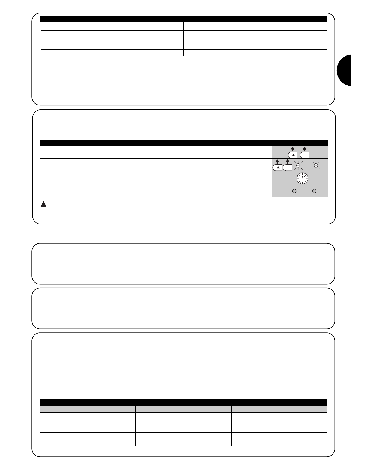
45
I
7.4.1) Funzione “Apri sempre”
La funzione “Apri sempre” è una proprietà della centrale di controllo
che permette di comandare sempre una manovra di apertura quando il comando di “Passo-Passo” ha una durata superiore a 2 secondi; ciò è utile ad esempio per collegare al morsetto P.P. il contatto di
un orologio programmatore per mantenere aperto il cancello per una
certa fascia oraria. Questa proprietà è valida qualunque sia la programmazione dell’ingresso di P.P. ad esclusione della programmazione come “Chiude”, vedere parametro “Funzione P.P.” in tabella 9.
7.4.2) Funzione “Muovi comunque”
Nel caso in cui qualche dispositivo di sicurezza non dovesse funzionare correttamente o fosse fuori uso, è possibile comunque comandare e muovere il cancello in modalità “Uomo presente”.
Per i dettagli vedere il paragrafo “Comando con sicurezze fuori uso”
presente nell’allegato “Istruzioni ed avvertenze destinate all’utilizzatore del motoriduttore ROBUS”.
7.4.3) Avviso di manutenzione
ROBUS consente di avvisare l’utente quando eseguire un controllo
di manutenzione dell’automazione. Il numero di manovre dopo il
quale avviene la segnalazione è selezionabile tra 8 livelli, mediante il
parametro regolabile “Avviso di manutenzione” (vedere tabella 9).
Il livello 1 di regolazione è “automatico” e tiene conto della gravosità
delle manovre, cioè dello sforzo e della durata della manovra, mentre le altre regolazioni sono fissate in base al numero delle manovre.
La segnalazione di richiesta di manutenzione avviene attraverso il lampeggiante Flash oppure sulla lampada collegata all'uscita S.C.A.
quando è programmata come "Spia Manutenzione" (vedere tabella 9).
In base al numero di manovre eseguite rispetto al limite programmato il lampeggiante Flash e la spia manutenzione danno le segnalazioni riportate in tabella 16.
7.4) Funzioni particolari
Tabella 14: programmazioni su ROBUS Slave indipendenti da ROBUS Master
Funzioni di primo livello (funzioni ON – OFF) Funzioni di secondo livello (parametri regolabili)
Stand-by Velocità Motore
Spunto Uscita SCA
Modo Slave Forza Motore
Lista Errori
Nello Slave è possibile collegare:
•
un proprio lampeggiante (Flash)
•
una propria Spia Cancello Aperto (S.C.A.)
•
un proprio bordo sensibile (Stop)
•
un proprio dispositivo di comando (P.P.) che comanda l'apertura totale solo dell'anta Slave.
•
Nello Slave gli ingressi Open e Close non vengono utilizzati
7.3.6) Apprendimento altri dispositivi
Normalmente l’operazione di apprendimento dei dispositivi collegati a BlueBUS ed all’ingresso STOP viene eseguita durante la fase di installazione;
tuttavia se vengono aggiunti o rimossi dispositivi è possibile rifare l’apprendimento come riportato in tabella 15.
1. Premere e tenere premuti i tasti [▲] e [Set]
2. Rilasciare i tasti quando i led L1 e L2 iniziano a lampeggiare molto velocemente (dopo circa 3s)
L1 L2
3. Attendere alcuni secondi che la centrale finisca l’apprendimento dei dispositivi
4. Al termine dell’apprendimento i led L1 e L2 smetteranno di lampeggiare, il led STOP deve rimanere
acceso, mentre i led L1…L8 si accenderanno in base allo stato delle funzioni ON-OFF che rappresentano. L1 L2
Dopo aver aggiunto o rimosso dei dispositivi è necessario eseguire nuovamente il collaudo dell’automazione secondo
quanto indicato nel paragrafo “5.1 Collaudo”.
!
Tabella 15: per l’apprendimento di altri dispositivi Esempio
SET
SET
Numero manovre Segnalazione su Flash Segnalazione si spia manutenzione
Inferiore a 80% del limite
Tra 81 e 100% del limite
Oltre il 100% del limite
Normale (0.5s acceso, 0.5s spento)
A inizio manovra rimane acceso per 2s poi
prosegue normalmente
Ad inizio e fine manovra rimane acceso per
2s poi prosegue normalmente
Accesa per 2s ad inizio apertura
Lampeggia durante tutta la manovra
Lampeggia sempre.
Tabella 16: avviso di manutenzione con Flash e spia manutenzione
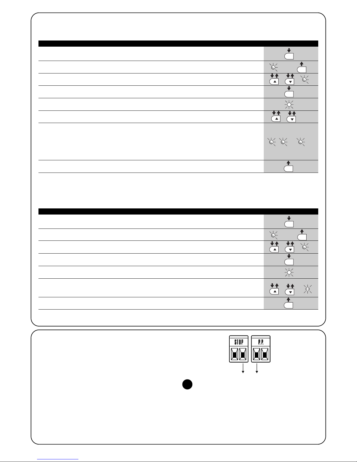
46
Verifica del numero di manovre effettuate
Con la funzione di “Avviso di manutenzione” è possibile verificare il numero di manovre eseguite in percentuale sul limite impostato. Per la
verifica procedere come descritto in tabella 17.
1. Premere e tener premuto il tasto [Set] per circa 3s
3s
2. Rilasciare il tasto [Set] quando il led L1 inizia a lampeggiare
L1
3. Premere i tasti [▲] o [▼] per spostare il led lampeggiante sul L7, cioè il “led di entrata” per il
parametro “Avviso si manutenzione” oL7
4. Premere e mantenere premuto il tasto [Set], il tasto [Set] va mantenuto premuto
durante tutti i passi 5, 6 e 7
5. Attendere circa 3s dopodiché si accenderà il led che rappresenta il livello attuale del
parametro “Avviso si manutenzione” 3s
6. Premere e subito rilasciare i tasti [▲] e [▼].
e
7. Il led corrispondente al livello selezionato farà alcuni lampeggi. Il numero di lampeggi identifica la
percentuale di manovre effettuate (in multipli di 10%) rispetto al limite impostato.
Ad esempio: con impostato l’avviso di manutenzione su L6 cioè 10000, il 10% corrisponde a 1000
manovre; se il led di visualizzazione fa 4 lampeggi, significa che è stato raggiunto il 40% delle manovre
(cioè tra 4000 e 4999 manovre). Se non è stato raggiunto il 10% delle manovre non ci sarà nessun
lampeggio.
8. Rilasciare il tasto [Set]
Tabella 17: verifica del numero di manovre effettuate Esempio
SET
SET
SET
SET
.... n=?
Azzeramento contatore manovre
Dopo aver eseguito la manutenzione dell’impianto è necessario azzerare il contatore delle manovre.
Procedere come descritto in tabella 18.
1. Premere e tener premuto il tasto [Set] per circa 3s
3s
2. Rilasciare il tasto [Set] quando il led L1 inizia a lampeggiare
L1
3. Premere i tasti [▲] o [▼] per spostare il led lampeggiante sul L7, cioè il “led di entrata” per il
parametro “Avviso si manutenzione” oL7
4. Premere e mantenere premuto il tasto [Set], il tasto [Set] va mantenuto premuto
durante tutti i passi 5, e 6
5. Attendere circa 3s dopodiché si accenderà il led che rappresenta il livello attuale del
parametro “Avviso si manutenzione” 3s
6. Premere e tenere premuto per almeno 5 secondi i tasti [▲] e [▼], quindi rilasciare i 2 tasti.
Il led corrispondente al livello selezionato eseguirà una serie di lampeggi veloci per segnalare che il
contatore delle manovre è stato azzerato.
e
7. Rilasciare il tasto [Set]
Tabella 18: azzeramento contatore manovre Esempio
SET
SET
SET
SET
7.5 Collegamento altri dispositivi
Se vi fosse l’esigenza di alimentare dispositivi esterni ad esempio un
lettore di prossimità per tessere a transponder oppure la luce d’illuminazione del selettore a chiave è possibile prelevare l’alimentazione
come indicato in figura 27. La tensione di alimentazione è 24Vcc 30% ÷ +50% con corrente massima disponibile di 100mA.
-+
24Vcc
27
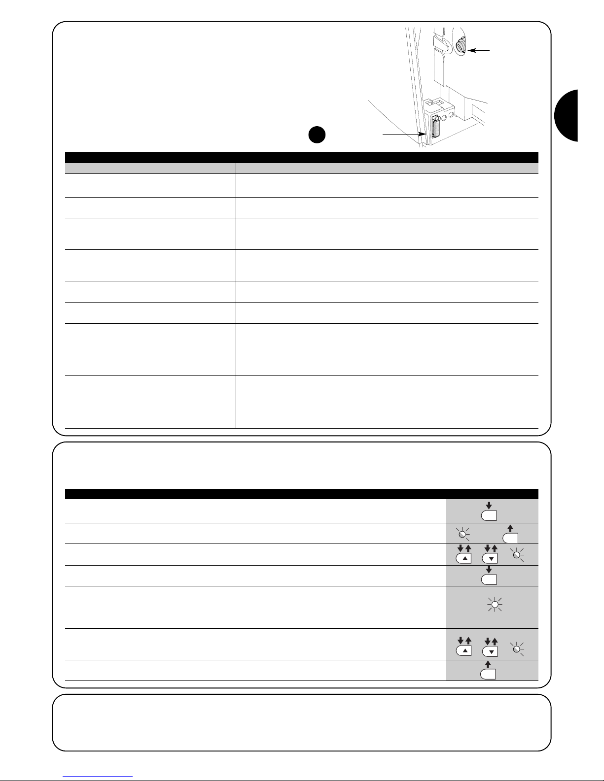
47
I
7.7) Diagnostica e segnalazioni
Alcuni dispositivi offrono direttamente delle segnalazioni particolari
attraverso le quali è possibile riconoscere lo stato di funzionamento
o dell’eventuale malfunzionamento.
7.6) Risoluzione dei problemi
Nella tabella 19 è possibile trovare utili indicazioni per affrontare gli
eventuali casi di malfunzionamento in cui è possibile incorrere durante l’installazione o in caso di guasto.
29
Tabella 19: ricerca guasti
Sintomi Verifiche consigliate
Il trasmettitore radio non comanda il cancello ed
il led sul trasmettitore non si accende
Il trasmettitore radio non comanda il cancello
ma il led sul trasmettitore si accende
Non si comanda nessuna manovra ed il led
“BlueBUS” non lampeggia
Non si comanda nessuna manovra ed il lampeggiante è spento
Non si comanda nessuna manovra ed il lampeggiante fa alcuni lampeggi
La manovra ha inizio ma subito dopo avviene
l'inversione
La manovra viene eseguita regolarmente ma il
lampeggiante non funziona
La manovra viene eseguita regolarmente ma la
spia SCA non funziona
Verificare che le pile del trasmettitore non siano scariche, eventualmente sostituirle
Verificare se il trasmettitore è correttamente memorizzato nel ricevitore radio
Verificare che ROBUS sia alimentato con la tensione di rete.
Verificare che i fusibili non siano interrotti; in questo caso, verificare la causa del guasto
e poi sostituirli con altri dello stesso valore di corrente e caratteristiche.
Verificare che il comando venga effettivamente ricevuto. Se il comando giunge sull'ingresso PP il relativo led “PP” deve accendersi; se invece viene utilizzato il trasmettitore
radio, il led “BluBus” deve fare due lampeggi veloci.
Contare il numero di lampeggi e verificare secondo quanto riportato in tabella 21
La forza selezionata potrebbe essere troppo bassa per il tipo di cancello. Verificare se
ci sono degli ostacoli ed eventualmente selezionare una forza superiore
Verificare che durante la manovra vi sia tensione sul morsetto FLASH del lampeggiante
(essendo intermittente il valore di tensione non è significativo: circa 10-30Vcc); se c'è
tensione, il problema è dovuto alla lampada che dovrà essere sostituita con una di
uguali caratteristiche; se non c'è tensione, potrebbe essersi verificato un sovraccarico
sull'uscita FLASH, verificare che non vi sia corto circuito sul cavo.
Verificare il tipo di funzione programmata per l'uscita SCA (Tabella 9)
Quando la spia dovrebbe essere accesa, verificare vi sia tensione sul morsetto SCA
(circa 24Vcc); se c'è tensione, il problema è dovuto alla spia che dovrà essere sostituita con una di uguali caratteristiche; se non c'è tensione, potrebbe essersi verificato un
sovraccarico sull'uscita SCA. verificare che non vi sia corto circuito sul cavo.
F2
F1
1. Premere e tener premuto il tasto [Set] per circa 3s
3s
2. Rilasciare il tasto [Set] quando il led L1 inizia a lampeggiare
L1
3. Premere i tasti [▲] o [▼] per spostare il led lampeggiante sul L8, cioè il “led di entrata”
per il parametro “Elenco anomalie” oL8
4. Premere e mantenere premuto il tasto [Set], il tasto [Set] va mantenuto premuto
durante tutti i passi 5, e 6
5. Attendere circa 3s dopodiché si accenderanno i led corrispondenti alle manovre che hanno avuto delle
anomalie. Il led L1 indica l’ esito della manovra più recente,il led L8 indica l’esito dell’ottava. Se il led è
acceso significa che durante la manovra si sono verificate delle anomalie; se il led è spento significa che
la manovra è terminata senza anomalie.
6. Premere i tasti i tasti [▲] e [▼] per selezionare la manovra desiderta:
Il led corrispondente farà un numero di lampeggi pari a quelli normalmente eseguiti dal lampeggiante
dopo un’anomalia (vedere tabella 21).
e
7. Rilasciare il tasto [Set]
Tabella 20: storico anomalie Esempio
SET
SET
SET
SET
7.6.1) Elenco storico anomalie
ROBUS permette di visualizzare le eventuali anomalie che si sono verificate nelle ultime 8 manovre, ad esempio l’interruzione di una manovra per l’intervento di una fotocellula o di un bordo sensibile. Per verificare l’elenco delle anomalie precedere come in tabella 20.
3s
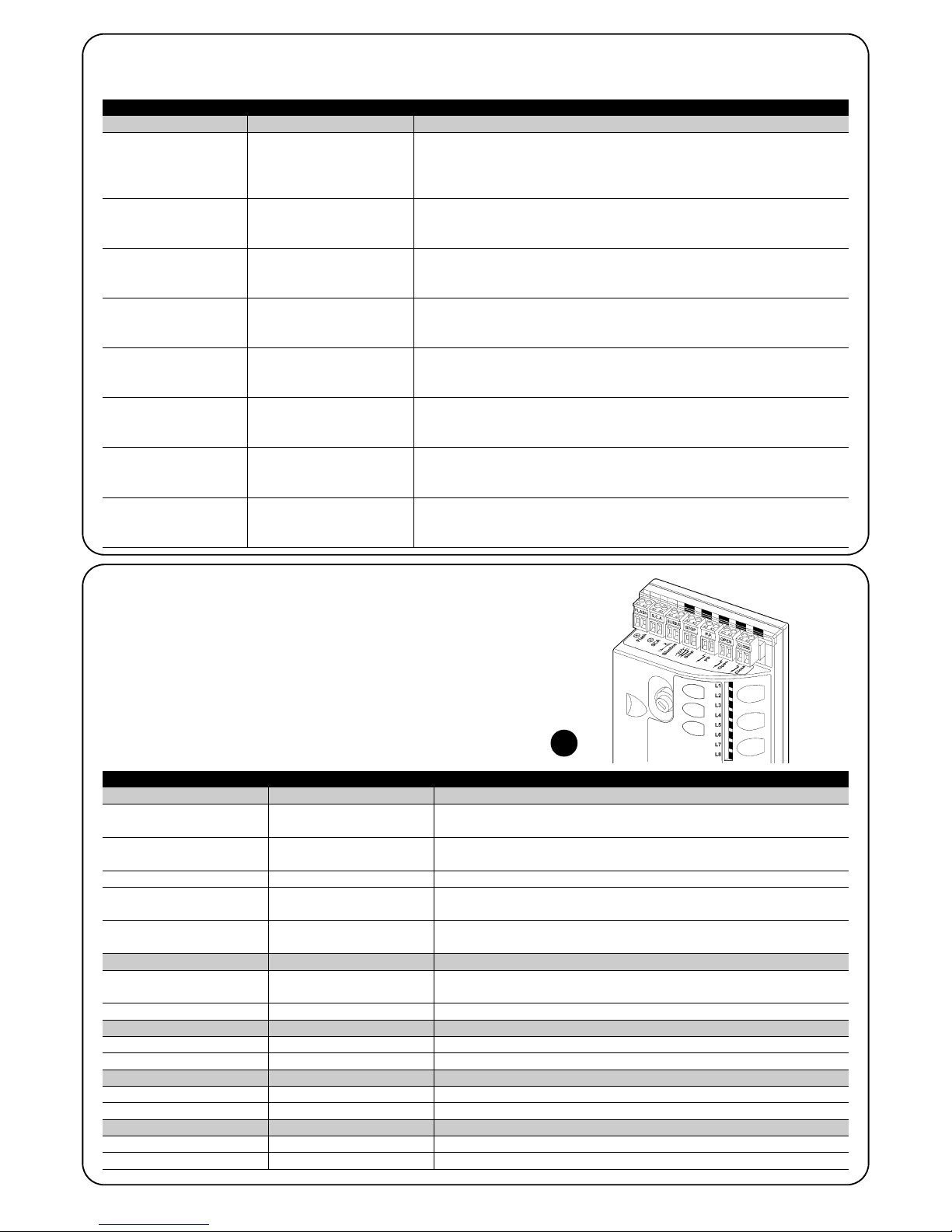
48
Led BLUEBUS Causa AZIONE
Led STOP Causa AZIONE
Led P.P. Causa AZIONE
Led APRE Causa AZIONE
Spento
7.7.2) Segnalazioni sulla centrale
Nella centrale di ROBUS ci sono una serie di LED ognuno dei quali
può dare delle segnalazioni particolari, sia nel funzionamento normale che in caso di anomalia.
Tabella 22: led sui morsetti della centrale
Anomalia
Verificare se c’è alimentazione; verificare che i fusibili non siano intervenuti; nel
caso, verificare la causa del guasto e poi sostituirli con altri dello stesso valore
Acceso Anomalia grave
C’è una anomalia grave; provare a spegnere per qualche secondo la centrale;
se lo stato permane c’è un guasto e occorre sostituire la scheda elettronica
Un lampeggio al secondo Tutto OK Funzionamento normale della centrale
2 lampeggi veloci
E’ avvenuta una variazione
dello stato degli ingressi
E’ normale quando avviene un cambiamento di uno degli ingressi: OPEN, STOP,
intervento delle fotocellule o viene utilizzato il trasmettitore radio
Serie di lampeggi separati da
una pausa di un secondo
Varie E’ la stessa segnalazione che c’è sul lampeggiante Vedere Tabella N°21
Spento
Intervento dell’ingresso di
STOP
Verificare i dispositivi collegati all’ingresso di STOP
Acceso Tutto OK Ingresso STOP attivo
Spento Tutto OK Ingresso PP non attivo
Acceso
Spento
Intervento dell’ingresso di PP
Tutto OK
E’ normale se è effettivamente attivo il dispositivo collegato all’ingresso PP
Ingresso APRE non attivo
Acceso
Intervento dell’ingresso di OPEN
E’ normale se è effettivamente attivo il dispositivo collegato all’ingresso APRE
Led CHIUDE Causa AZIONE
Spento Tutto OK Ingresso CHIUDE non attivo
Acceso
Intervento dell’ingresso di CLOSE
E’ normale se è effettivamente attivo il dispositivo collegato all’ingresso CHIUDE
29
6 lampeggi
pausa di 1 secondo
6 lampeggi
All’inizio della manovra, la verifica dei dispositivi collegati a BLUEBUS non corrisponde a quelli memorizzati durante la fase di apprendimento. E’ possibile vi
siano dispositivi guasti, verificare e sostituire; se sono state fatte delle modifiche
occorre rifare l’apprendimento
7.7.1) Segnalazioni con il lampeggiante
Il segnalatore lampeggiante FLASH durante la manovra esegue un lampeggio ogni secondo; quando accadono delle anomalie, vengono
emessi dei lampeggi più brevi; i lampeggi si ripetono due volte, separati da una pausa di un secondo.
Tabella 21: segnalazioni sul lampeggiante FLASH
Lampeggi veloci Causa AZIONE
1 lampeggio
pausa di 1 secondo
1 lampeggio
Errore sul BluBUS
2 lampeggi
pausa di 1 secondo
2 lampeggi
Intervento di una fotocellula
All’inizio della manovra una o più fotocellule non danno il consenso al movimento, verificare se ci sono ostacoli.
Durante il movimento è normale se effettivamente è presente un ostacolo.
3 lampeggi
pausa di 1 secondo
3 lampeggi
Intervento del limitatore della
“Forza Motore”
Durante il movimento il cancello ha incontrato un maggiore attrito;
verificare la causa
4 lampeggi
pausa di 1 secondo
4 lampeggi
Intervento dell’ingresso di
STOP
All’inizio della manovra o durante il movimento c’è stato un intervento dell’ingresso di STOP; verificare la causa
5 lampeggi
pausa di 1 secondo
5 lampeggi
Errore nei parametri interni
della centrale elettronica
Attendere almeno 30 secondi e riprovare a dare un comando; se lo stato rimane potrebbe esserci un guasto grave ed occorre sostituire la scheda elettronica
Superato il limite massimo
di manovre per ora.
Attendere alcuni minuti che il limitatore di manovre ritorni sotto il limite massimo
7 lampeggi
pausa di 1 secondo
7 lampeggii
8 lampeggi
pausa di 1 secondo
8 lampeggi
Errore nei circuiti elettrici
interni
E ‘ già presente un comando che non consente di
eseguire altri comandi.
Scollegare tutti i circuiti di alimentazione per qualche secondo poi riprovare a
dare un comando; se lo stato rimane potrebbe esserci un guasto grave ed
occorre sostituire la scheda elettronica
Verificare la natura del comando sempre presente; ad esempio potrebbe essere il comando da un orologio sull’ingresso di “apre”.

49
I
7.8) Accessori
Per ROBUS sono previsti i seguenti accessori opzionali:
• PS124 Batteria tampone 24V - 1,2Ah con caricabatteria integrato.
• SMXI o SMXIS Ricevitore radio a 433.92MHz con codifica digitale
Rolling Code.
Consultare il catalogo prodotti di Nice S.p.a. per l’elenco completo
ed aggiornato degli accessori.
30
Led 1 Descrizione
• Programmazione delle funzioni in corso
• Se lampeggia assieme ad L4 indica che è necessario eseguire la fase di apprendimento della lunghezza
dell’anta (vedere paragrafo “4.4 Apprendimento lunghezza dell’ anta”).
Led L6 Descrizione
Led L5 Descrizione
Led L3 Descrizione
Led L2 Descrizione
Led L4 Descrizione
Durante il funzionamento normale indica “Spunto” non attivo.Spento
Spento
Tabella 23: led sui tasti della centrale
Durante il funzionamento normale indica “Chiusura automatica” non attiva
Durante il funzionamento normale indica “Chiusura automatica” attiva
• Programmazione delle funzioni in corso
• lampeggia assieme ad L2 indica che è necessario eseguire la fase di apprendimento dei dispositivi
(vedere paragrafo “4.3 Apprendimento dei dispositivi”).
Acceso
Lampeggia
Spento Durante il funzionamento normale indica “Richiudi Dopo Foto” non attivo.
Durante il funzionamento normale indica “Richiudi Dopo Foto” attivo.
• Programmazione delle funzioni in corso
• Se lampeggia assieme ad L1 indica che è necessario eseguire la fase di apprendimento dei dispositivi
(vedere paragrafo “4.3 Apprendimento dei dispositivi”).
Acceso
Lampeggia
Spento Durante il funzionamento normale indica “Chiude Sempre” non attivo.
Durante il funzionamento normale indica “Chiude Sempre” attivo.
Durante il funzionamento normale indica “Stand-By” non attivo.
Durante il funzionamento normale indica “Stand-By” attivo.
• Programmazione delle funzioni in corso
• Se lampeggia assieme ad L3 indica che è necessario eseguire la fase di apprendimento della lunghezza
dell’anta (vedere paragrafo “4.4 Apprendimento lunghezza dell’ anta”).
Acceso
Lampeggia
Spento
Acceso
Lampeggia
Durante il funzionamento normale indica “Spunto” attivo.
Programmazione delle funzioni in corso
Acceso
Lampeggia
Durante il funzionamento normale indica “Prelampeggio” non attivo.
Durante il funzionamento normale indica “Prelampeggio” attivo.
Programmazione delle funzioni in corso
Spento
Acceso
Lampeggia
Led L7 Descrizione
Durante il funzionamento normale indica che l’ingresso CHIUDE attiva una manovra di chiusura
Durante il funzionamento normale indica che l’ingresso CHIUDE attiva una manovra di apertura parziale.
Programmazione delle funzioni in corso
Spento
Acceso
Lampeggia
Led L8 Descrizione
Durante il funzionamento normale indica che ROBUS è configurato come Master
Durante il funzionamento normale indica che ROBUS è configurato come Slave
Programmazione delle funzioni in corso
Spento
Acceso
Lampeggia
31

50
Utilizzo in atmosfera particolarmente acida
o salina o potenzialmente esplosiva
330 x 210 h 303; 11Kg 330 x 210 h 303; 13 Kg
Con lo scopo di migliorare i propri prodotti, Nice S.p.a si riserva il diritto di modificare le caratteristiche tecniche in qualsiasi momento e senza preavviso pur mantenendo funzionalità e destinazione d’uso.
Tutte le caratteristiche tecniche riportate si riferiscono alla temperatura ambientale di 20°C (±5°C).
8) Caratteristiche tecniche
Tipologia
Modello tipo
Caratteristiche tecniche ROBUS
Motoriduttore elettromeccanico per il movimento automatico di cancelli scorrevoli per uso
residenziale completo di centrale elettronica di controllo
RB600 – RB600P RB1000 – RB1000P
Pignone Z: 15; Modulo: 4; Passo: 12,6 mm; Diametro primitivo: 60mm
Coppia massima allo spunto
[corrispondente alla capacità di sviluppare
una forza per mettere in movimento l’anta]
18Nm
[600N]
27Nm
[900N]
Coppia nominale
[corrispondente alla capacità di sviluppare
una forza per mantenere in movimento l’anta]
9Nm
[300N]
15Nm
[500N]
Velocità alla coppia nominale
0,15m/s 0,14m/s
Velocità a vuoto (la centrale consente di
programmare 6 velocità pari a circa: 100,
85, 70, 55, 45, 30%)
0,31m/s 0,28m/s
Frequenza massima cicli di funzionamento
(alla coppia nominale)
100 cicli / giorno (la centrale limita i cicli al
massimo previsto nelle tabelle 2 e 3)
150 cicli / giorno (la centrale limita i cicli al
massimo previsto nelle tabelle 2 e 3)
Tempo massimo funzionamento continuo
(alla coppia nominale)
7 minuti
(la centrale limita il funzionamento continuo
al massimo previsto nelle tabelle 2 e 3)
5 minuti
(la centrale limita il funzionamento continuo
al massimo previsto nelle tabelle 2 e 3)
Limiti d’impiego
Generalmente ROBUS è in grado di automatizzare cancelli con peso oppure lunghezza
secondo i limiti riportati nelle tabelle 2, 3 e 4
Durabilità Stimata tra 20.000 cicli e 250.000 cicli, secondo delle condizioni riportate in tabella 4
Potenza massima assorbita allo spunto
[corrispondenti ad Ampere]
515W [2,5A] [4,8A versione /V1] 450W [2,3A] [4,4A versione /V1]
Classe di isolamento 1 (è necessaria la messa a terra di sicurezza)
Alimentazione di emergenza con accessorio opzionale PS124
Uscita lampeggiante per 2 lampeggianti LUCYB (lampada 12V, 21W)
Uscita BLUEBUS una uscita con carico massimo di 15 unità BlueBus
Uscita S.C.A
per 1 lampada 24V massimo 4W (la tensione d’uscita può variare tra –30 e +50% e può
comandare anche piccoli relè)
Ingresso STOP
Per contatti normalmente chiusi, normalmente aperti oppure a resistenza costante 8,2KΩ; in
auto apprendimento (una variazione rispetto allo stato memorizzato provoca il comando “STOP”)
Ingresso PP per contatti normalmente aperti (la chiusura del contatto provoca il comando P.P.)
Ingresso APRE
Ingresso CHIUDE
per contatti normalmente aperti (la chiusura del contatto provoca il comando APRE)
per contatti normalmente aperti (la chiusura del contatto provoca il comando CHIUDE)
Innesto radio Connettore SM per ricevitori SMXI o SMXIS
Ingresso ANTENNA Radio 52Ω per cavo tipo RG58 o simili
Alimentazione ROBUS 600 – 1000
Alimentazione ROBUS 600 – 1000/V1
230Vac (+10% -15%) 50/60Hz.
120Vac (+10% -15%) 50/60Hz.
Funzioni programmabili 8 funzioni di tipo ON-OFF e 8 funzioni regolabili (vedere tabelle 7 e 9)
Temperatura di funzionamento -20°C ÷ 50°C
No
Grado di protezione IP 44
Dimensioni e peso
Funzioni in auto apprendimento
Auto apprendimento dei dispositivi collegati all'uscita BlueBus
Auto apprendimento del tipo di dispositivo di "STOP" (contatto NA, NC o resistenza
8,2KΩ) Auto apprendimento della lunghezza del cancello e calcolo dei punti di rallenta-
mento ed apertura parziale.

51
I
Complimenti per aver scelto per la vostra automa-
zione un prodotto Nice! Nice S.p.a. produce componenti per l’automazione di cancelli, porte,serrande,
tapparelle e tende da sole: motoriduttori, centrali di
comando,radiocomandi, lampeggianti, fotocellule e
accessori. Nice utilizza solo materiali e lavorazioni di
qualità, e per vocazione ricerca soluzioni innovative
che semplifichino al massimo l’utilizzo delle sue apparecchiature, curate nelle soluzioni tecniche, estetiche,
ergonomiche: nella grande gamma Nice il vostro installatore avrà senz’altro scelto il prodotto più adatto alle
vostre esigenze. Nice non è però il produttore della
vostra automazione, che è invece il risultato di un’opera di analisi, valutazione, scelta dei materiali, e realizzazione dell’impianto eseguita dal vostro installatore di
fiducia. Ogni automazione è unica e solo il vostro
installatore possiede l’esperienza e la professionalità
necessarie ad eseguire un impianto secondo le vostre
esigenze, sicuro ed affidabile nel tempo, e soprattutto
a regola d’arte, rispondente cioè alle normative in vigore. Un impianto di automazione è una bella comodità,
oltre che un valido sistema di sicurezza e, con poche,
semplici attenzioni, è destinato a durare negli anni.
Anche se l’automazione in vostro possesso soddisfa il
livello di sicurezza richiesto dalle normative, questo
non esclude l’esistenza di un “rischio residuo”, cioè la
possibilità che si possano generare situazioni di pericolo, solitamente dovute ad un utilizzo incosciente o
addirittura errato, per questo motivo desideriamo darvi alcuni consigli sui comportamenti da seguire per evitare ogni inconveniente:
•Prima di usare per la prima volta l’automazio-
ne, fatevi spiegare dall’installatore l’origine dei rischi
residui, e dedicate qualche minuto alla lettura del
manuale di istruzioni ed avvertenze per l’utiliz-
zatore consegnatovi dall’installatore. Conservate il
manuale per ogni dubbio futuro e consegnatelo ad un
eventuale nuovo proprietario dell’automazione.
•La vostra automazione è un macchinario che
esegue fedelmente i vostri comandi; un uso
incosciente ed improprio può farlo diventare pericoloso: non comandate il movimento dell’automazione
se nel suo raggio di azione si trovano persone, animali o cose.
•Bambini: un impianto di automazione garantisce un
alto grado di sicurezza, impedendo con i suoi sistemi
di rilevazione il movimento in presenza di persone o
cose, e garantendo un’attivazione sempre prevedibile e sicura. È comunque prudente vietare ai bambini
di giocare in prossimità dell’automazione e per evitare attivazioni involontarie non lasciare i telecomandi
alla loro portata: non è un gioco!
•Anomalie: Non appena notate qualunque comportamento anomalo da parte dell’automazione, togliete
alimentazione elettrica all’impianto ed eseguite lo
sblocco manuale. Non tentate da soli alcuna ripara-
zione, ma richiedete l’intervento del vostro installatore di fiducia: nel frattempo l’impianto può funzionare
come un’apertura non automatizzata, una volta
sbloccato il motoriduttore come descritto più avanti.
•Manutenzione: Come ogni macchinario la vostra
automazione ha bisogno di una manutenzione periodica affinché possa funzionare più a lungo possibile
ed in completa sicurezza. Concordate con il vostro
installatore un piano di manutenzione con frequenza
periodica; Nice consiglia un intervento ogni 6 mesi
per un normale utilizzo domestico, ma questo periodo può variare in funzione dell’intensità d’uso. Qualunque intervento di controllo, manutenzione o riparazione deve essere eseguito solo da personale qualificato.
•Anche se ritenete di saperlo fare, non modificate l’impianto ed i parametri di programmazione e di regolazione dell’automazione: la responsabilità è del vostro
installatore.
• Il collaudo, le manutenzioni periodiche e le eventuali
riparazioni devono essere documentate da chi le esegue e i documenti conservati dal proprietario dell’impianto.
Gli unici interventi che vi sono possibili e vi consigliamo di effettuare periodicamente sono la pulizia dei
vetrini delle fotocellule e la rimozione di eventuali foglie
o sassi che potrebbero ostacolare l’automatismo. Per
impedire che qualcuno possa azionare il cancello, prima di procedere, ricordatevi di sbloccare l’automa-
tismo (come descritto più avanti) e di utilizzare per la
pulizia solamente un panno leggermente inumidito con
acqua.
• Smaltimento: Al termine della vita dell’automazione, assicuratevi che lo smantellamento sia eseguito
da personale qualificato e che i materiali vengano riciclati o smaltiti secondo le norme valide a livello locale.
• In caso di rotture o assenza di alimentazione:
Attendendo l’intervento del vostro installatore, o il
ritorno dell’energia elettrica se l’impianto non è dotato di batterie tampone, l’automazione può essere
azionata come una qualunque apertura non automatizzata. Per fare ciò è necessario eseguire lo sblocco
manuale (unico intervento consentito all’utente sull’automazione): tale operazione è stata particolarmente studiata da Nice per assicurarvi sempre la
massima facilità di utilizzo, senza uso di attrezzi particolari o necessità di sforzo fisico.
Istruzioni ed avvertenze destinate all’utilizzatore del motoriduttore ROBUS

52
Sblocco e movimento manuale: prima di eseguire questa operazione porre attenzione che lo sblocco può
avvenire solo quando l’anta è ferma.
Per bloccare: eseguire, al contrario le stesse operazioni
Comando con sicurezze fuori uso: nel caso i
dispositivi di sicurezza presenti nel cancello non
dovessero funzionare correttamente è possibile
comunque comandare il cancello.
• Azionare il comando del cancello (col telecomando,
col selettore a chiave, ecc.); se tutto è a posto il
cancello si aprirà o chiuderà normalmente, altrimenti il lampeggiante farà alcuni lampeggi e la manovra
non partirà (il numero di lampeggi dipende dal motivo per cui la manovra non può partire).
• In questo caso, entro tre secondi si deve azionare
nuovamente e tenere azionato il comando.
• Dopo circa 2s inizierà il movimento del cancello in
modalità a “uomo presente”, cioè finché si mantiene
il comando, il cancello continuerà a muoversi; appena il comando viene rilasciato, il cancello si ferma.
Con le sicurezze fuori uso è necessario far
riparare quanto prima l’automatismo.
Sostituzione pila del telecomando: se il vostro
radiocomando dopo qualche tempo vi sembra funzionare peggio, oppure non funzionare affatto, potrebbe
semplicemente dipendere dall’esaurimento della pila (a
seconda dell’uso, possono trascorrere da diversi mesi
fino ad oltre un anno). Ve ne potete accorgere dal fatto che la spia di conferma della trasmissione non si
accende, è fioca, oppure si accende solo per un breve
istante. Prima di rivolgervi all’installatore provate a
scambiare la pila con quella di un altro trasmettitore
eventualmente funzionante: se questa fosse la causa
dell’anomalia, sarà sufficiente sostituire la pila con altra
dello stesso tipo.
Le pile contengono sostanze inquinanti: non gettarle
nei rifiuti comuni ma utilizzare i metodi previsti dai
regolamenti locali.
Siete soddisfatti? Nel caso voleste aggiungere nella vostra casa un nuovo impianto di automazione, rivolgendovi allo stesso installatore e a Nice vi garantirete,
oltre che la consulenza di uno specialista e i prodotti
più evoluti del mercato, il migliore funzionamento e la
massima compatibilità delle automazioni.
Vi ringraziamo per aver letto queste raccomandazioni,
e vi auguriamo la massima soddisfazione dal vostro
nuovo impianto: per ogni esigenza presente o futura
rivolgetevi con fiducia al vostro installatore.
!
1 Far scorrere il dischetto copri serratura. 2 Inserire e ruotare la chiave in senso orario.
3 Tirare la maniglia di sblocco. 4 Muovere manualmente l’anta.


54
Table des matières: page
1 Avertissements 55
2 Description du produit et type d'utilisation 56
2.1 Limites d'utilisation 56
2.2 Installation typique 58
2.3 Liste des câbles 58
3 Installation 59
3.1 Contrôles préliminaires 59
3.2 Fixation de l'opérateur 59
3.3 Fixation des pattes de fin de course dans les
versions avec fin de course inductif 60
3.4 Installation des divers dispositifs 61
3.5 Connexions électriques 61
3.6 Description des connexions électriques 62
4 Contrôles finaux et mise en service 62
4.1 Sélection de la direction 62
4.2 Branchement au secteur 62
4.3 Reconnaissance des dispositifs 62
4.4 Reconnaissance de la longueur du portail 63
4.5 Vérification du mouvement du portail 63
4.6 Fonctions préprogrammées 63
4.7 Récepteur radio 63
5 Essai et mise en service 63
5.1 Essai 64
5.2 Mise en service 64
6 Maintenance et mise au rebut 64
6.1 Maintenance 64
6.2 Mise au rebut 64
7 Approfondissements 65
7.1 Touches de programmation 65
7.2 Programmations 65
7.2.1 Fonctions premier niveau (fonctions ON-OFF) 65
7.2.2 Programmation du premier niveau
(fonctions ON-OFF) 66
7.2.3 Fonctions deuxième niveau
(paramètres réglables) 66
7.2.4 Programmation deuxième niveau
(paramètres réglables) 67
7.2.5 Exemple de programmation premier niveau
(fonctions ON-OFF) 68
7.2.6 Exemple de programmation deuxième niveau
(paramètres réglables) 68
7.3 Ajout ou enlèvement de dispositifs 68
7.3.1 BlueBUS 68
7.3.2 Entrée STOP 69
7.3.3 Photocellules 69
7.3.4 Photodétecteur FT210B 69
7.3.5 ROBUS en mode “Slave” 70
7.3.6 Reconnaissance d'autres dispositifs 71
7.4 Fonctions particulières 71
7.4.1 Fonction “Ouvre toujours” 71
7.4.2 Fonction “Manœuvre dans tous les cas” 71
7.4.3 Avis de maintenance 71
7.5 Connexion d'autres dispositifs 72
7.6 Résolution des problèmes 73
7.6.1 Liste historique des anomalies 73
7.7 Diagnostic signalisations 73
7.7.1 Signalisations avec le clignotant 74
7.7.2 Signalisations sur la logique de commande 74
7.8 Accessoires 75
8 Caractéristiques techniques 76
Instructions et recommandations destinées à l'utilisateur
de l'opérateur ROBUS 77
Robus
600/600P
1000/1000P

55
F
1) Avertissements
Ce manuel d'instructions contient des informations importantes concernant la sécurité pour l'installation, il faut lire toutes les instructions avant
de procéder à l'installation. Conserver avec soin ce manuel également
pour des consultations futures.
Compte tenu des dangers qui peuvent se vérifier durant l'installation et
l'utilisation de ROBUS, pour le maximum de sécurité il faut que l'installation soit faite dans le plein respect des lois, normes et règlements.
Dans ce chapitre, nous donnons des recommandations d'ordre général;
d'autres recommandations importantes se trouvent dans les chapitres
“3.1 Contrôles préliminaires”; “5 Essai et mise en service”
D'après la législation européenne la plus récente, la réalisation d'une porte ou d'un portail automatique est réglementée par la Directive 98/37/CE (Directive Machines) et en
particulier par les normes: EN 13241-1 (norme harmonisée),
EN 12445, EN 12453 et EN 12635 qui permettent de déclarer
la conformité à la directive machines.
D'autres informations et les conseils pour l'analyse des risques et la réalisation du dossier technique sont disponibles sur le site: www.niceforyou.com.
Le présent manuel est destiné uniquement au personnel technique qualifié pour l'installation. À part l'encart spécifique “Instructions et recommandations destinées à l'utilisateur de l'opérateur ROBUS” qui sera
détaché par l'installateur, aucune autre information contenue dans la
présente notice ne peut être considérée comme intéressante pour l'utilisateur final!
• Une utilisation de ROBUS différente de ce qui est prévu dans cette
notice est interdite; des utilisations impropres peuvent être source de
dangers ou de dommages aux personnes et aux choses.
• Avant de commencer l'installation, il faut effectuer l'analyse des
risques comprenant la liste des conditions de sécurité requises par
l'annexe I de la Directive Machines, en indiquant les solutions adoptées.
Nous rappelons que l'analyse des risques est l'un des documents qui
constituent le “dossier technique” de l'automatisation.
• Vérifier la nécessité d'autres dispositifs pour compléter l'automatisa-
tion avec ROBUS suivant les conditions spécifiques de l'application et
les risques présents; il faut considérer par exemple les risques d'impact, écrasement, cisaillement, coincement, etc., et d'autres dangers
en général.
• Ne pas effectuer de modifications sur aucune des parties si elles ne
sont pas prévues dans le présent manuel. Des opérations de ce type
entraîneront obligatoirement des problèmes de fonctionnement. NICE
décline toute responsabilité pour les dommages dérivant de produits
modifiés.
• Pendant l'installation et l'utilisation, éviter que des parties solides ou
liquides puissent pénétrer à l'intérieur de la logique de commande ou
d'autres composants ouverts; s'adresser éventuellement au service
d'assistance NICE; l'utilisation de ROBUS dans de telles circonstances peut créer des situations de danger
• L'automatisme ne peut pas être utilisé avant d'avoir effectué la mise
en service comme l'explique le chapitre: “5 Essai et mise en service”.
• L'emballage de ROBUS doit être mis au rebut dans le plein respect
des normes locales en vigueur.
• Dans le cas de panne qui ne peut pas être résolue avec les informa-
tions données dans ce manuel, contacter le service après-vente NICE.
• Si des interrupteurs automatiques ou des fusibles interviennent, avant
de les réarmer il faut identifier la cause de leur déclenchement et l'éliminer.
• Avant d'accéder aux bornes situées sous le carter de ROBUS décon-
necter tous les circuits d'alimentation; si le dispositif de déconnexion
n'est pas visible, accrocher un panonceau: “ATTENTION MAINTENANCE EN COURS”.
Avertissements particuliers sur l'appropriation à l'utilisation de ce produit
par rapport à la Directive “Machines” 98/37/CE (ex 89/392/CEE):
• Ce produit est mis sur le marché comme “composant de machine” et
est donc construit pour être incorporé dans une machine ou pour être
assemblé avec d'autres appareillages afin de réaliser “une machine”
selon les termes de la Directive 98/37/CE seulement en association
avec les autres composants et dans les modes décrits dans ce
manuel d'instructions. Comme le prévoit la directive 98/37/CE nous
rappelons que la mise en service de ce produit n'est pas autorisée tant
que le constructeur de la machine dans laquelle ce produit est incorporé ne l'a pas identifié et déclaré conforme à la directive 98/37/CE.
Avertissements particuliers sur l'appropriation à l'utilisation de ce produit
par rapport à la Directive “Basse Tension” 73/23/CEE et modification
successive 93/68/CEE:
• Ce produit est conforme aux caractéristiques requises par la Directive
“Basse Tension” s'il est employé pour l'application et dans les configurations prévues dans ce manuel d'instructions et en association
avec les articles présents dans le catalogue produits de Nice S.p.a.
Les caractéristiques pourraient ne pas être garanties si le produit est
utilisé dans des configurations ou avec d'autres produits non prévus;
l'utilisation du produit dans ces situations est interdite tant que l'on a
pas vérifié que les critères prévus par la directive sont respectés.
Avertissements particuliers sur l'appropriation à l'utilisation de ce produit
par rapport à la Directive “Compatibilité électromagnétique” 89/336/CEE
et modifications successives 92/31/CEE et 93/68/CEE:
• ce produit a été soumis aux essais relatifs à la compatibilité électromagnétique dans les situations d'utilisation les plus critiques, dans les
configurations prévues dans ce manuel d'instructions et associé avec
les articles présents dans le catalogue de produits de Nice S.p.A. La
compatibilité électromagnétique pourrait ne pas être garantie si le produit est utilisé dans des configurations ou avec d'autres produits non
prévus; l'utilisation du produit dans ces situations est interdite tant que
l'on n'a pas vérifié que les critères prévus par la directive sont respectés.
!

56
ROBUS est une ligne d'opérateurs électromécaniques irréversibles
destinés à l'automatisation de portails coulissants. Ils disposent
d'une logique électronique de commande et d'un connecteur pour
le récepteur de la radiocommande SMXI ou SMXIS (en option). Les
connexions électriques vers les dispositifs extérieurs sont simplifiées
grâce à la technique “BlueBUS” qui permet de connecter plusieurs
dispositifs avec seulement 2 fils. ROBUS fonctionne à l'énergie électrique, en cas de coupure du courant, il est possible de débrayer
l'opérateur avec une clé spéciale et de manœuvrer le portail à la
main. En alternative, on peut utiliser l'accessoire en option: la batterie tampon PS124 qui permet quelques manœuvres même en l'absence du courant de secteur.
Les produits décrits dans le tableau 1 font partie de la ligne ROBUS.
Note: 1 kg = 9,81 N donc par exemple: 600 N = 61 kg
2) Description du produit et type d'utilisation
1
Opérateur type RB600 RB600P RB1000 RB1000P
Type de fin de course électromécanique de proximité inductif électromécanique de proximité inductif
Longueur maximum du portail 8m 12m
Poids maximum du portail 600Kg 1000Kg
Couple maximum au démarrage 18Nm 27Nm
(correspondant à une force de) (600N) (900N)
Moteur et transformateur Moteur 24Vcc Ø 77mm Moteur 24Vcc Ø 115mm
Transformateur à colonne EI Transformateur toroïdal
Tableau 1: comparaison des caractéristiques essentielles des opérateurs ROBUS
2.1) Limites d'utilisation
Les données relatives aux performances de ROBUS figurent dans le
chapitre “8 Caractéristiques techniques” et sont les seules valeurs
qui permettent d'évaluer correctement si l'opérateur est adapté à
l'application.
Les caractéristiques structurales des produits ROBUS permettent
de les utiliser sur des portails coulissants, dans les limites indiquées
dans les tableaux 2, 3 et 4.
Le fait que ROBUS soit réellement adapté à automatiser un portail
donné dépend des frictions et d'autres phénomènes, qui peuvent
être occasionnels, comme la présence de glace qui pourrait bloquer
le mouvement du portail.
Pour une vérification réelle, il est absolument indispensable de
mesurer la force nécessaire pour manœuvrer le portail sur toute sa
course et contrôler que la force ne dépasse pas la moitié du “couple
nominal” indiqué au chapitre “8 Caractéristiques techniques”
(nous conseillons une marge de 50% car des conditions climatiques
critiques peuvent faire augmenter les frictions); par ailleurs, pour établir
le nombre de cycles/heure, les cycles consécutifs et la vitesse maximum autorisée, il faut considérer les données des tableaux 2 et 3.
RB600, RB600P RB1000, RB1000P
Longueur du portail (m) cycles/heure maximums
cycles consécutifs maximums
cycles/heure maximums
cycles consécutifs maximums
Jusqu'à 4 40 20 50 25
4 ÷ 6 25 13 33 16
6 ÷ 8 20 10 25 12
8 ÷ 10 --- --- 20 10
10 ÷ 12 --- --- 16 8
Tableau 2: limites suivant la longueur du portail
330mm 210mm
303mm
92mm
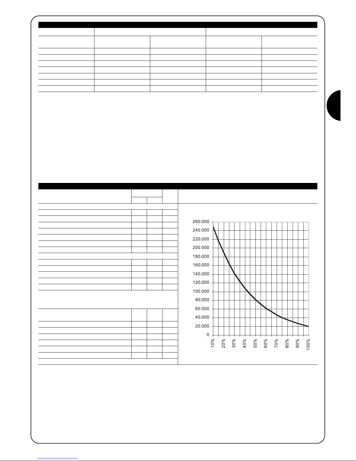
57
F
La longueur du portail permet de calculer le nombre maximum de cycles à l'heure et de cycles consécutifs tandis que le poids permet de calculer le pourcentage de réduction des cycles et la vitesse maximum admissible; par exemple, pour ROBUS 1000, si le portail mesure 5 m de long,
on peut avoir 33 cycles/heure et 16 cycles consécutifs mais si le portail pèse 700 kg, il faut les réduire à 50%, soit 16 cycles/heure et environ 8
cycles consécutifs tandis que la vitesse maximum admissible est V4: rapide. Pour éviter les surchauffes, la logique de commande prévoit un limiteur de manœuvres qui se base sur l'effort du moteur et la durée des cycles en intervenant quand la limite maximum est dépassée. Le limiteur de
manœuvres mesure aussi la température ambiante en réduisant encore plus les manœuvres en cas de température particulièrement élevée.
Le chapitre “8 Caractéristiques techniques” donne une estimation de “durabilité” c'est-à-dire de vie économique moyenne du produit. La valeur
est fortement influencée par l'indice de charge de travail des manœuvres, c'est-à-dire la somme de tous les facteurs qui concourent à l'usure.
Pour effectuer l'estimation, il faut additionner tous les indices de charge de travail du tableau 4, puis avec le résultat total, vérifier dans le graphique
la durabilité estimée.
Par exemple, ROBUS 1000 sur un portail de 650 kg, de 5 m de long, équipé de photocellules et sans autres éléments de fatigue, obtient un indice de charge de travail égal à 50% (30+10+10). D'après le graphique, la durabilité estimée est de 80.000 cycles.
RB600, RB600P RB1000, RB1000P
Poids portail en (kg) Pourcentage cycles Vitesse maximum Pourcentage cycles Vitesse maximum
admissible admissible
Jusqu'à 200 100% V6 = Super rapide 100% V6 = Super rapide
200 ÷ 400 80 V5 = Très rapide 90 V5 = Très rapide
400 ÷ 500 60 V4 = Rapide 75 V4 = Rapide
500 ÷ 600 50 V3 = Moyenne 60 V4 = Rapide
600 ÷ 800 --- --- 50 V3 = Moyenne
800 ÷ 900 --- --- 45 V3 = Moyenne
900 ÷ 1000 --- --- 40 V3 = Moyenne
Tableau 3: limites suivant le poids du portail
Indice de charge de travail % Robus Durabilité en cycles
600 1000
Poids du portail en kg
Jusqu'à 200 10 5
200 ÷ 400 30 10
400 ÷ 600 50 20
600 ÷ 700 --- 30
700 ÷ 800 --- 40
800 ÷ 900 --- 50
900 ÷ 1000 --- 60
Longueur du portail en mètres
Jusqu'à 4 10 5
4 ÷ 6 20 10
6 ÷ 8 35 20
8 ÷ 10 --- 35
10 ÷ 12 --- 50
Autres éléments de fatigue
(à considérer si la probabilité
qu'ilsse vérifient est supérieure à 10 % )
Température ambiante supérieure à 40°C ou
inférieure à 0°C ou humidité supérieure à 80%
10 10
Présence de poussière ou de sable 15 15
Présence de sel 20 20
Interruption manœuvre par Photo 15 10
Interruption manœuvre par Halte 25 20
Vitesse supérieure à “L4 rapide” 20 15
Augm. du couple au démarrage activée 25 20
Total indice de charge de travail:
N.B.: si l'indice de charge de travail dépasse 100%, cela veut dire que l'on a dépassé les conditions d'acceptabilité; nous conseillons d'utiliser un
modèle de taille supérieure.
Tableau 4: estimation de la durabilité en fonction de l'indice de charge de travail de la manœuvre
Indice de charge de travail %
Durabilité en cycles

58
2.2) Installation typique
La figure 2 présente l'installation typique pour l'automatisation d'un portail de type coulissant utilisant ROBUS
2
1 Sélecteur à clé
2 Photocellules sur colonne
3 Photocellules
4 Bord primaire fixe (option)
5 Bord primaire mobile
6 Patte de fin de course “Ouvert”
7 Crémaillère
8 Bord secondaire fixe (option)
9 Clignotant avec antenne incorporée
10 ROBUS
11 Patte de fin de course “Fermé”
12 Bord secondaire mobile (option)
13 Émetteur radio
2.3) Liste des câbles
Dans l'installation typique de la figure 2 sont indiqués aussi les câbles nécessaires pour les connexions des différents dispositifs; le tableau
5 indique les caractéristiques des câbles.
Les câbles utilisés doivent être adaptés au type d'installation; par exemple, on conseille un câble type H03VV-F pour la pose
à l'intérieur ou H07RN-F pour la pose à l'extérieur.
!
Note 1: si le câble d'alimentation dépasse 30 m, il faut prévoir un câble avec une section plus grande, par exemple 3 x 2,5 mm_ et une
mise à la terre est nécessaire à proximité de l'automatisme.
Note 2: si le câble “BlueBUS” dépasse 30 m, jusqu'à un maximum de 50 m, il faut prévoir un câble 2 x 1
mm
2
.
Note 3: les deux câbles 2 x 0,5
mm
2
peuvent être remplacés par un seul câble 4 x 0,5 mm2.
Note 4: s'il y a plus d'un bord sensible, voir le chapitre “7.3.2 Entrée STOP” pour le type de connexion conseillée.
Note 5: pour la connexion des bords sensibles mobiles sur les parties coulissantes, il faut utiliser des dispositifs ad hoc qui permettent la
connexion même quand le portail est en mouvement.
Connexion Type de câble Longueur maximum admise
A: Ligne électrique d'alimentation 1 câble 3 x 1,5 mm
2
30 m (note 1)
B: Clignotant avec antenne 1 câble 2 x 0,5 mm
2
20m
1 câble blindé type RG58 20m (longueur conseillée: moins de 5 m)
C: Photocellules 1 câble 2 x 0,5 mm
2
30 m (note 2)
D: Sélecteur à clé 2 câbles 2 x 0,5 mm2(note 3) 50 m
E: Bords sensibles fixes 1 câble 2 x 0,5 mm2(note 4) 30 m
F: Bords sensibles mobiles 1 câble 2 x 0,5 mm2(note 4) 30 m (note 5)
Tableau 5: Liste des câbles
2
43 38
10
2
6
11
7
9
13
1251
EC F
D
C
F
A
B

59
F
3.2) Fixation de l'opérateur
Si la surface d'appui existe déjà, la fixation de l'opérateur doit être effectuée directement sur la surface en utilisant des moyens adéquats par
exemple avec des chevilles à expansion. Autrement, pour fixer l'opérateur:
1. Creuser un trou de fondation de dimensions adéquates en suivant
les mesures indiquées dans la Figure 3.
2. Prévoir un ou plusieurs conduits pour le passage des câbles comme dans la Figure 4.
3. Assembler les deux agrafes sur la plaque de fondation en plaçant
un écrou en dessous et un au-dessus de la plaque; l'écrou sous
la plaque doit être vissé à fond comme dans la figure 5 de manière
que la partie filetée de l'agrafe dépasse d'environ 25÷35 mm audessus de la plaque.
4. Effectuer la coulée en ciment et avant qu'il commence à prendre,
mettre la plaque de fondation en respectant les distances indiquées
dans la figure 3; vérifier qu'elle est parallèle au portail et parfaitement
de niveau (fig. 6). Attendre la prise complète du ciment.
5. Enlever les 2 écrous sur le dessus de la plaque puis y poser l'opérateur; vérifier qu'il est parfaitement parallèle au portail puis visser
légèrement les 2 écrous et les rondelles fournies comme dans la
figure 7.
L'installation de ROBUS doit être effectuée par du personnel qualifié, dans le respect des lois, des normes et des règle-
ments ainsi que de toutes les instructions de ce manuel.
!
3) Installation
3.1) Contrôles préliminaires
Avant de continuer l'installation de ROBUS il faut effectuer les
contrôles suivants:
• Vérifier que tout le matériel à utiliser est en excellent état, adapté à
l'usage et conforme aux normes.
• Vérifier que la structure du portail est adaptée pour être équipée
d'un automatisme.
• Vérifier que le poids et les dimensions du portail rentrent dans les
limites d'utilisation indiquées au chapitre “2.1 Limites d'utilisation”.
• Vérifier, en comparant avec les valeurs figurant dans le chapitre “8
Caractéristiques techniques”, que la force nécessaire pour mettre le
portail en mouvement est inférieure à la moitié du “Couple maximum” et que la force nécessaire pour maintenir le portail en mouvement est inférieure à la moitié du “Couple nominal”; on conseille une
marge de 50% sur les forces car les conditions climatiques adverses
peuvent faire augmenter les frictions.
• Vérifier que dans la course du portail, aussi bien en fermeture qu'en
ouverture, il n'y a pas de points présentant une plus grande friction.
• Vérifier que le portail ne risque pas de dérailler et de sortir des rails
de guidage.
• Vérifier la robustesse des butées mécaniques de limitation de la
course en contrôlant qu'il n'y a pas de déformations même en cas
de heurt violent du portail sur la butée.
• Vérifier que le portail est bien équilibré, c'est-à-dire qu'il ne doit pas
bouger s'il est laissé arrêté dans une position quelconque.
• Vérifier que la zone de fixation de l'opérateur n'est pas sujette à
inondation; éventuellement, monter l'opérateur suffisamment soulevé par rapport au sol.
• Vérifier que la zone de fixation de l'opérateur permet la manœuvre
de débrayage de manière facile et sûre.
• Vérifier que les points de fixation des différents dispositifs se trouvent
dans des endroits à l'abri des chocs et que les surfaces sont suffisamment solides.
• Éviter que les parties de l'automatisme puissent être immergées
dans l'eau ou dans d'autres substances liquides.
• Ne pas placer ROBUS à proximité de flammes ou de sources de
chaleur, dans des atmosphères potentiellement explosives, particulièrement acides ou salines; cela pourrait endommager ROBUS et
causer des problèmes de fonctionnement ou des situations de danger.
• Si le portail coulissant est muni d'un portillon pour le passage de piétons incorporé ou dans la zone de manœuvre du portail, il faut s'assurer que ce portillon ne gêne pas la course normale et prévoir éventuellement un système d'interverrouillage.
• Connecter la logique de commande à une ligne d'alimentation électrique avec mise à la terre.
• La ligne d'alimentation électrique doit être protégée par un disjoncteur magnétothermique associé à un déclencheur différentiel.
• Sur la ligne d'alimentation du secteur électrique, il faut monter un
dispositif de déconnexion de l'alimentation (avec catégorie de surtension III, c'est-à-dire avec une distance entre les contacts d'au
moins 3,5 mm) ou bien un autre système équivalent par exemple prise + fiche. Si le dispositif de déconnexion de l'alimentation ne se
trouve pas à proximité de l'automatisme, il faut disposer d'un système de blocage contre la connexion accidentelle ou non autorisée.
3
4
5
6
25÷35
7
192
330 0÷50
0÷50 330
192
0÷10
0÷10

60
3.3) Fixation des pattes de fin de course dans les versions avec fin de course de proximité inductif
Pour éviter que le portail pèse trop sur l'opérateur, il
est important qu'il y ait un jeu d'1÷2 entre la crémaillère
et le pignon, comme dans la figure 10.
8. Faire coulisser le portail et utiliser toujours le pignon comme réfé-
rence pour fixer les autres éléments de la crémaillère.
9. Couper l'éventuelle partie de crémaillère qui dépasse sur le der-
nier segment.
10. Effectuer différentes manœuvres d'ouverture et de fermeture du
portail à la main et vérifier que la crémaillère coulisse alignée au
pignon avec un désalignement maximum de 5 mm, et qu'il y a un
jeu d'1÷2 mm entre le pignon et la crémaillère sur toute la longueur.
11. Serrer énergiquement les écrous de fixation de l'opérateur en
s'assurant qu'il est bien fixé au sol; couvrir les écrous de fixation
avec les bouchons comme dans la figure 11.
12. Fixer les pattes de fin de course suivant la description donnée ciaprès (pour les versions RB600P et RB1000P fixer les pattes
suivant la description du “3.3 Fixation des pattes de fin de course dans les versions avec fin de course de proximité inductif”):
• Porter manuellement le portail en position d'ouverture en s'ar-
rêtant à au moins 2 - 3 cm de la butée mécanique.
• Faire coulisser la patte sur la crémaillère dans le sens de l'ouver-
ture jusqu'à l'intervention du fin de course. Faire avancer ensuite
la patte d'au moins 2 cm puis la bloquer sur la crémaillère avec
les goujons correspondants comme sur la figure 12.
• Effectuer la même opération pour le fin de course de fermeture.
13.Bloquer l'opérateur comme l'indique le paragraphe “Débrayage
et mouvement manuel” dans le chapitre “Instructions et recommandations destinées à l'utilisateur.
!
8 9 10
11 12
Si la crémaillère est déjà présente, après avoir fixé l'opérateur, agir sur
les goujons de réglage comme dans la figure 8 pour mettre le pignon
de ROBUS à la hauteur qui convient en laissant 1÷2 mm de jeu de la
crémaillère. Autrement, pour fixer la crémaillère, il faut:
6. Débrayer l'opérateur suivant les indications du paragraphe “Débrayage et manœuvre manuelle” dans le chapitre “Instructions et recommandations destinées à l'utilisateur de l'opérateur ROBUS”.
7. Ouvrir complètement le portail, poser sur le pignon le premier segment de crémaillère et vérifier que le début de la crémaillère correspond au début du portail comme sur la figure 9. Vérifier la présence d'un jeu d'1÷2 mm entre le pignon et la crémaillère, puis fixer la
crémaillère sur le portail avec des moyens adéquats.
1÷2
Pour les versions RB600P et RB1000P qui utilisent le fin de course
de proximité inductif, il faut fixer les pattes de fin de course suivant
les indications données ci-après.
1. Porter manuellement le portail en position d'ouverture en s'arrêtant à au moins 2 - 3 cm de la butée mécanique.
2. Faire coulisser la patte sur la crémaillère dans le sens de l'ouverture jusqu'à l'extinction de la led correspondante, comme dans la
figure 13. Faire avancer ensuite la patte d'au moins 2 cm puis la
bloquer sur la crémaillère avec les goujons correspondants.
3. Porter manuellement le portail en position de fermeture en s'arrêtant à au moins 2 - 3 cm de la butée mécanique.
4. Faire coulisser la patte sur la crémaillère dans le sens de la fermeture jusqu'à l'extinction de la led correspondante. Faire avancer ensuite la patte d'au moins 2 cm puis la bloquer sur la crémaillère avec les goujons correspondants.
Attention: dans le fin de course de proximité inductif, la
distance optimale de la patte est comprise entre 3 et 8 mm,
comme l'indique la figure 14.
!
13
14
3÷8

61
F
3.5) Connexions électriques
Toutes les connexions électriques doivent être effectuées
en l'absence de tension dans l'installation et avec l'éventuelle batterie tampon déconnectée.
1. Pour éliminer le couvercle de protection et accéder à la logique élec-
tronique de commande de ROBUS il faut enlever la vis sur le côté et
retirer le couvercle en le tirant vers le haut.
2. Enlever la membrane en caoutchouc qui bouche le trou pour le pas-
sage des câbles et enfiler tous les câbles de connexion vers les différents dispositifs en les laissant dépasser de 20÷30 cm. Voir le tableau
3 pour le type de câble et la figure 2 pour les connexions.
3.
Réunir avec un collier de serrage tous les câbles qui entrent dans l'opé-
rateur, placer le collier juste en dessous du trou d'entrée des câbles.
Sur la membrane de caoutchouc, découper un trou un peu plus étroit
que le diamètre des câbles regroupés et enfiler la membrane le long des
câbles jusqu'au collier; remettre ensuite la membrane dans le trou pour
le passage des câbles. Mettre un deuxième collier de serrage pour
regrouper les câbles juste au-dessus de la membrane.
4. Connecter le câble d'alimentation sur la borne prévue à cet effet comme l'indique la figure 15 puis avec un collier de serrage, bloquer le
câble au premier anneau serre-câbles.
5. Effectuer les connexions des autres câbles suivant le schéma de la
figure 17. Pour plus de commodité, les bornes peuvent être extraites.
6. Après avoir terminé les connexions, bloquer avec des colliers de serrage les câbles regroupés au deuxième anneau serre-câbles, la partie
du câble d'antenne en excès doit être bloquée avec les autres câbles
à l'aide d'un autre collier comme l'indique la figure 16.
!
3.4) Installation des divers dispositifs
Installer les autres dispositifs prévus en suivant les instructions respectives. Vérifier dans le paragraphe “3.6 Description des connexions électriques” et dans la figure 2 les dispositifs qui peuvent être connectés à ROBUS.
15
17
16
Pour connecter 2 moteurs sur des parties coulissantes opposées, voir le paragraphe “7.3.5 ROBUS en mode Slave”.
LUCYB
S.C.A.
MOFB MOSE
OPEN CLOSE

62
3.6) Description des connexions électriques
Ce paragraphe contient une brève description des connexions électriques; d'autres informations se trouvent dans le paragraphe “7.3
Ajout ou enlèvement de dispositifs”.
FLASH: sortie pour clignotant type “LUCYB” ou similaires avec l'ampoule 12 V maximum 21 W.
S.C.A.: sortie “Voyant portail ouvert”; il est possible de connecter
une ampoule de signalisation 24 V maximum 4 W. Elle peut être programmée aussi pour d'autres fonctions; voir paragraphe “7.2.3
Fonctions deuxième niveau”
BLUEBUS: sur cette borne, on peut connecter les dispositifs compatibles; ils sont tous connectés en parallèle avec seulement deux
conducteurs sur lesquels transitent aussi bien l'alimentation électrique que les signaux de communication. D'autres informations sur
BlueBUS se trouvent dans le paragraphe “7.3.1 BlueBUS”.
STOP: entrée pour dispositifs qui bloquent ou éventuellement arrêtent la manœuvre en cours; en adoptant certaines solutions sur l'entrée, il est possible de connecter des contacts type “Normalement
Fermé”, “Normalement Ouvert” ou des dispositifs à résistance
constante. D'autres informations sur STOP se trouvent dans le paragraphe “7.3.2 Entrée STOP”.
P. P. : entrée pour dispositifs qui commandent le mouvement en
mode Pas à Pas; on peut y connecter des contacts de type “Normalement Ouvert”.
OPEN: entrée pour dispositifs qui commandent le mouvement d'ouverture uniquement; on peut y connecter des contacts de type “Normalement Ouvert”.
CLOSE: entrée pour dispositifs qui commandent le mouvement de
fermeture uniquement; on peut y connecter des contacts de type
“Normalement Ouvert”.
ANTENNE: entrée pour la connexion de l'antenne pour récepteur
radio (l'antenne est incorporée sur LUCY B).
Avant de commencer la phase de contrôle et de mise en service de l'automatisme, il est conseillé de mettre le portail à mi-course environ
de manière qu'il puisse se déplacer aussi bien en ouverture qu'en fermeture.
4) Contrôles finaux et mise en service
4.1) Sélection de la direction
La direction de la manœuvre d'ouverture doit être choisie en fonction
de la position de l'opérateur par rapport au portail; si le portail doit
coulisser vers la gauche pour l'ouverture, il faut mettre le sélecteur
vers la gauche comme dans la figure 18, si le portail doit coulisser
vers la droite pour l'ouverture, il faut mettre le sélecteur vers la droite comme dans la figure 19.
18
19
4.2) Branchement au secteur
Le branchement de ROBUS au secteur doit être effectué par du personnel expert et qualifié en possession des
caractéristiques requises et dans le plein respect des lois,
normes et réglementations.
Dès que l'opérateur ROBUS est alimenté, il est conseillé de faire
quelques vérifications élémentaires:
1. Vérifier que la led BLUEBUS clignote régulièrement à la fréquen-
ce d'un clignotement à la seconde.
2. Vérifier que les led sur les photocellules clignotent elles aussi
(aussi bien sur TX que sur RX); la fréquence de clignotement n'est
pas significative, elle est liée à d'autres facteurs.
3. Vérifier que le clignotant connecté à la sortie FLASH et que le
voyant connecté sur la sortie S.C.A. sont éteints.
Si ce n'est pas le cas, il faut couper immédiatement l'alimentation de
la logique de commande et contrôler plus attentivement les
connexions électriques.
D'autres informations utiles pour la recherche et le diagnostic des
pannes se trouvent dans le chapitre “7.6 Résolution des problèmes”
!
4.3) Reconnaissance des dispositifs
Après le branchement au secteur il faut faire reconnaître par la logique de commande les dispositifs connectés aux entrées BLUEBUS et
STOP. Avant cette phase, les led L1 et L2 clignotent pour indiquer qu'il faut effectuer la reconnaissance des dispositifs.
La phase de reconnaissance des dispositifs connectés peut être refaite à tout moment même après l'installation, par exemple si l'on ajoute
un dispositif; pour effectuer la nouvelle reconnaissance, voir paragraphe “7.3.6 Reconnaissance d'autres dispositifs
1. Presser et maintenir enfoncées les touches [▲] et [Set]
2. Relâcher les touches quand les led L1 et L2 commencent à clignoter très rapidement
(au bout d'environ 3 s)
3. Attendre quelques secondes que la logique termine la reconnaissance des dispositifs
4. À la fin de la reconnaissance, la led STOP doit rester allumée, les led L1 et L2 s'éteindront (les led L3
et L4 commenceront éventuellement à clignoter)
20

63
F
4.4) Reconnaissance de la longueur du portail
Après la reconnaissance des dispositifs, les led L3 et L4 commenceront à clignoter; cela signifie qu'il faut faire reconnaître la longueur du
portail (distance entre le fin de course de fermeture et le fin de course d'ouverture); cette mesure est nécessaire pour le calcul des points de
ralentissement et le point d'ouverture partielle.
Si tout cela ne se vérifie pas, il faut couper immédiatement l'alimentation de la logique de commande et contrôler plus attentivement les
connexions électriques. D'autres informations utiles se trouvent dans le chapitre “7.6 Résolution des problèmes”
1. Presser et maintenir enfoncées les touches [▼] et [Set]
2. Relâcher les touches quand la manœuvre commence (au bout d'environ 3 s)
3. Vérifier que la manœuvre en cours est une ouverture, autrement presser la touche [Stop] et relire attentive-
ment le paragraphe “4.1 Sélection de la direction”; puis répéter à partir du point 1.
4. Attendre que la logique complète la manœuvre d'ouverture jusqu'à ce que le fin de course d'ouverture soit
atteint; la manœuvre de fermeture commence juste après.
5. Attendre que la logique complète la manœuvre de fermeture.
4.5) Vérification du mouvement du portail
Après la reconnaissance de la longueur du portail, il est conseillé d'effectuer quelques manœuvres pour vérifier que le mouvement du portail est
correct.
1. Presser la touche [Open] pour commander une manœuvre d'ouver-
ture; vérifier que l'ouverture du portail s'effectue régulièrement sans
variation de vitesse; le portail ne doit ralentir que lorsqu'il se trouve
70÷50 cm avant le fin de course et il doit s'arrêter, suite à l'intervention du fin de course, à 2÷3cm de la butée mécanique d'ouverture.
2. Presser la touche [Close] pour commander une manœuvre de
fermeture; vérifier que la fermeture du portail s'effectue régulièrement sans variation de vitesse; le portail ne doit ralentir que lorsqu'il se trouve 70÷50 cm avant le fin de course et il doit s'arrêter,
suite à l'intervention du fin de course, à 2÷3cm de la butée mécanique de fermeture.
3. Durant la manœuvre, vérifier que le clignotant clignote à une fréquence régulière de 0,5 s. S'il est présent, contrôler également le clignotement du voyant connecté à la borne SCA: clignotement lent en ouverture, rapide en fermeture.
4. Effectuer différentes manœuvres d'ouverture et de fermeture pour
mettre en évidence les éventuels défauts de montage et de réglage ou
d'autres anomalies comme par exemple les points de plus grande friction.
5. Vérifier que les fixations de l'opérateur ROBUS, de la crémaillère et des
pattes de fin de course sont solides, stables et suffisamment résistantes même en cas de brusques accélérations ou décélérations du
mouvement du portail
4.6) Fonctions préprogrammées
La logique de commande de ROBUS dispose de certaines fonctions
programmables; en usine ces fonctions sont réglées suivant une
configuration qui devrait satisfaire la plupart des automatisations;
quoiqu'il en soit, les fonctions peuvent être modifiées à tout moment
à l'aide d'une procédure de programmation particulière, voir pour
cela le paragraphe “7.2 Programmations”.
21
4.7) Récepteur radio
Pour la commande à distance de ROBUS, la logique de commande est munie d'un connecteur SM pour récepteurs radio type SMXI ou
SMXIS en option. Pour tout renseignement supplémentaire, consulter le manuel d'instructions du récepteur radio. Pour embrocher le récepteur radio effectuer l'opération indiquée dans la figure 22.
Dans le tableau 6, on trouve décrite l'association entre la sortie du récepteur radio et la commande que ROBUS exécutera:
22
Sortie N°1 Commande “PP” (Pas à Pas)
Sortie N°2 Commande “Ouverture partielle”
Sortie N°3 Commande“Ouverture”
Sortie N°4 Commande “Fermeture”
Tableau 6: commandes avec émetteur
Il s'agit des phases les plus importantes dans la réalisation de l'automatisation afin de garantir la sécurité maximum. L'essai peut être
utilisé également comme vérification périodique des dispositifs qui
composent l'automatisme.
L'essai de toute l'installation doit être effectué par du personnel qualifié et expérimenté qui devra se charger d'établir
les essais prévus en fonction des risques présents et de vérifier le respect de ce qui est prévu par les lois, les normes et
réglementations et en particulier, toutes les conditions de la
norme EN 12445 qui détermine les méthodes d'essai pour la
vérification des automatismes pour portails.
!
5) Essai et mise en service

64
5.1) Essai
Chaque élément de l'automatisme comme par exemple les bords sensibles, les photocellules, l'arrêt d'urgence, etc. demande une phase spécifique d'essai; pour ces dispositifs, il faudra effectuer les procédures figurant dans les manuels d'instructions respectifs.
Pour l'essai de ROBUS effectuer les opérations suivantes:
1. Vérifier que tout ce qui est prévu dans le présent manuel est rigoureusement respecté et en particulier dans le chapitre “1 Avertissements”;
2. Débrayer l'opérateur suivant les indications du paragraphe “Débrayage et manœuvre manuelle” dans le chapitre “Instructions et recommandations destinées à l'utilisateur de l'opérateur ROBUS”;
3. Vérifier qu'il est possible de manœuvrer manuellement le portail en
ouverture et en fermeture avec une force ne dépassant pas 390 N
(environ 40 kg);
4. Bloquer l'opérateur.
5. En utilisant les dispositifs de commande ou d'arrêt prévus (sélecteur
à clé, boutons de commande ou émetteurs radio), effectuer des
essais d'ouverture, de fermeture et d'arrêt du portail et vérifier que le
comportement du portail correspond à ce qui est prévu.
6. Vérifier un par un le fonctionnement correct de tous les dispositifs de
sécurité présents dans l'installation (photocellules, barres palpeuses,
arrêt d'urgence, etc.); et vérifier que le comportement du portail correspond à ce qui est prévu. À chaque fois qu'un dispositif intervient, la
led “BlueBUS” sur la logique de commande doit effectuer 2 clignotements plus rapides qui confirment qu'elle reconnaît l'événement.
7. Si l'on n'a pas remédié aux situations de risque liées au mouvement
du portail à travers la limitation de la force d'impact, il faut effectuer la
mesure de la force d'impact suivant les prescriptions de la norme EN
12445. Si le réglage de la “Vitesse” et le contrôle de la “Force moteur”
sont utilisés pour aider le système à réduire la force d'impact, essayer
et trouver les réglages qui donnent les meilleurs résultats.
5.2) Mise en service
La mise en service ne peut être faite que si toutes les phases d'essai de
ROBUS et des autres dispositifs ont été exécutées avec résultat positif.
La mise en service partielle ou dans des situations “provisoires” n'est pas
autorisée.
1. Réaliser et conserver au moins 10 ans le fascicule technique de l'automatisation qui devra comprendre au moins: dessin d'ensemble de
l'automatisation, schéma des connexions électriques, analyse des
risques et solutions adoptées, déclaration de conformité du fabricant
de tous les dispositifs utilisés (pour ROBUS, utiliser la Déclaration CE
de conformité ci-jointe), exemplaire du mode d'emploi et du plan de
maintenance de l'automatisme.
2. Appliquer sur le portail une plaquette contenant au moins les données
suivantes: type d'automatisme, nom et adresse du constructeur (responsable de la “mise en service”), numéro de matricule, année de
construction et marque “CE”.
3. Fixer de manière permanente à proximité du portail une étiquette
ou une plaque indiquant les opérations à effectuer pour le
débrayage et la manœuvre manuelle.
4. Remplir et remettre au propriétaire la déclaration de conformité de
l'automatisme.
5. Réaliser et remettre au propriétaire de l'automatisme le manuel “Instructions et avertissements pour l'utilisation de l'automatisme”.
6. Réaliser et remettre au propriétaire le plan de maintenance de
l'automatisme (qui doit regrouper toutes les prescriptions pour la
maintenance de chaque dispositif).
7. Avant de mettre en service l'automatisme, informer le propriétaire, de manière adéquate et par écrit (par exemple dans le manuel
d'instructions et d'avertissements pour l'utilisation de l'automatisme), sur les risques encore présents.
Ce chapitre contient les informations pour la réalisation du plan de maintenance et la mise au rebut de ROBUS
6) Maintenance et mise au rebut
6.1) Maintenance
Pour maintenir le niveau de sécurité et pour garantir la durée maximum
de tout l'automatisme, il faut effectuer une maintenance régulière; dans
ce but, ROBUS dispose d'un compteur de manœuvres et d'un système
de signalisation de maintenance nécessaire; voir paragraphe “7.4.3 Avis
de maintenance”.
La maintenance doit être effectuée dans le plein respect
des consignes de sécurité du présent manuel et suivant les
prescriptions des lois et normes en vigueur.
Si d'autres dispositifs sont présents, suivre ce qui est prévu dans le plan
de maintenance respectif.
1. Pour ROBUS il faut effectuer une maintenance programmée au maximum dans les 6 mois ou quand 20 000 manœuvres ont été effectuées depuis la dernière intervention de maintenance:
2. Couper toutes les sources d'alimentation électrique de l'automatisme,
y compris les éventuelles batteries tampon.
3. Vérifier l'état de détérioration de tous les matériaux qui composent
l'automatisme avec une attention particulière pour les phénomènes
d'érosion ou d'oxydation des parties structurelles; remplacer les parties qui ne donnent pas de garanties suffisantes.
4. Vérifier l'état d'usure des parties en mouvement: pignon, crémaillère
et toutes les parties mobiles du portail, remplacer les parties usées.
5. Reconnecter les sources d'alimentation électrique et effectuer tous les
essais et les contrôles prévus dans le paragraphe “5.1 Essai”.
!
6.2) Mise au rebut
ROBUS est constitué de différents types de matériaux dont certains
peuvent être recyclés (acier, aluminium, plastique, câbles électriques),
d'autres devront être mis au rebut (batteries et cartes électroniques).
certains composants électroniques et les batteries
pourraient contenir des substances polluantes, ne pas les
abandonner dans la nature. Informez-vous sur les systèmes de recyclage ou de mise au rebut en respectant les
normes locales en vigueur.
1. Déconnecter l'alimentation électrique de l'automatisme et l'éventuelle
batterie tampon.
2. Démonter tous les dispositifs et accessoires, suivant la procédure
inverse à celle qui est décrite dans le chapitre 3 “Installation”.
3. Séparer le plus possible les parties qui peuvent ou doivent être recyclées ou éliminées de manière différente, par exemple séparer les parties métalliques des parties en plastique, les cartes électroniques, les
batteries, etc.
4. Trier et confier les différents matériaux ainsi séparés et recyclables à
des sociétés spécialisées dans la récupération et le recyclage suivant
les réglementations locales.
!

65
F
Ce chapitre explique les possibilités de programmation et de personnalisation, ainsi que le diagnostic et la recherche des pannes sur ROBUS
7) Approfondissements
7.1) Touches de programmation
Sur la logique de commande de ROBUS se trouvent 3 touches qui peuvent être utilisées aussi
bien pour la commande de la logique durant les essais que pour les programmations:
23
7.2) Programmation
La logique de commande de ROBUS possède quelques fonctions programmables; le réglage des fonctions s'effectue à travers 3 touches présentes sur la logique: [▲] [Set] [▼] et sont visualisées à l'aide de 8 led:
L1….L8.
Les fonctions programmables disponibles sur ROBUS sont réparties en
deux niveaux:
Premier niveau: fonctions réglables en mode ON-OFF (actif ou non
actif); dans ce cas, chaque led L1….L8 indique une fonction, si elle est
allumée la fonction est active, si elle est éteinte la fonction n'est pas active; voir tableau 7.
Deuxième niveau: paramètres réglables sur une échelle de valeurs
(valeurs d'1 à 8); dans ce cas, chaque led L1….L8 indique la valeur
réglée parmi les 8 possibles; voir tableau 9.
Led Fonction Description
L1 Fermeture automatique Cette fonction permet une fermeture automatique du portail après le temps de pause programmé; le Temps de
pause est réglé en usine à 30 secondes mais peut être modifié à 5, 15, 30, 45, 60, 80, 120 et 180 secondes.
Si la fonction n'est pas active, le fonctionnement est “semi-automatique”.
L2 Refermeture immédiate
Cette fonction permet de garder le portail ouvert uniquement le temps nécessaire au transit, en effet après passage
devant passage l'intervention de “Photo” provoque toujours une refermeture automatique avec un temps de pause de 5 s
photocellule
(indépendamment de la valeur programmée); le comportement varie suivant si la “Fermeture
Automatique” est active ou pas.
Si la “Fermeture automatique” n'est pas active: le portail atteint toujours la position d'ouverture totale
(même si la libération de la photocellule a lieu avant). La libération de la photocellule provoque une
manœuvre de fermeture automatique au bout de 5 s.
Avec la “fermeture automatique” active: la manœuvre d'ouverture s'arrête juste après que les
photocellules aient été libérées et 5 s plus tard la manœuvre de fermeture automatique commence.
La fonction “Refermeture immédiate après passage devant photocellule” est toujours désactivée dans les
manœuvres interrompues avec une commande de Stop. Si la fonction “Refermeture immédiate après
passage devant photocellule” n'est pas active, le temps de pause sera celui qui est programmé ou bien il
n'y aura pas de refermeture automatique si la fonction n'est pas active.
L3 Ferme toujours La fonction “Ferme toujours” intervient, en provoquant une fermeture, quand au retour de l'alimentation la
logique détecte le portail ouvert. Pour des questions de sécurité, la manœuvre est précédée par 5 s de
préclignotement. Si la fonction n'est pas active au retour de l'alimentation, le portail restera arrêté.
L4 Stand-By Cette fonction permet de réduire au maximum la consommation d'énergie, elle est utile en particulier dans
le fonctionnement avec batterie tampon. Si cette fonction est active, 1 minute après la fin de la manœuvre,
la logique éteint BLUEBUS (et donc les dispositifs) et toutes les led sauf la led BLUEBUS qui clignotera
plus lentement. Quand une commande arrive, la logique rétablit le plein fonctionnement.
Si la fonction n'est pas active, il n'y aura pas de réduction des consommations.
L5 Démarrage Avec l'activation de cette fonction, l'accélération progressive au début de chaque manœuvre est
désactivée; cela permet d'avoir la force de démarrage maximum et c'est utile en cas de frictions statiques
élevées, par exemple en cas de neige ou de givre qui bloquent le portail. Si la fonction n'est pas active, la
manœuvre commence avec une accélération progressive.
L6 Préclignotement Avec la fonction de préclignotement, une pause de 3 s est ajoutée entre l'allumage du clignotant et le
début de la manœuvre pour avertir l'utilisateur de la situation de danger. Si la fonction n'est pas active,
l'allumage du clignotant coïncide avec le début de la manœuvre.
L7 “Fermeture” devient En activant cette fonction, toutes les commandes “fermeture” (entrée “CLOSE” ou commande radio “fermeture”)
“Ouverture partielle” activent une manœuvre d'ouverture partielle (voir led L6 sur tableau 9).
L8 Mode “Slave” (esclave) En activant cette fonction ROBUS devient “Slave” (esclave): il est possible, ainsi, de synchroniser le fonctionnement
de 2 moteurs sur des parties coulissantes opposées dans lesquelles un moteur fonctionne comme Master
(maître) et un comme Slave (esclave); pour plus de détails, voir le paragraphe “7.3.5 ROBUS en mode “Slave”.
Durant le fonctionnement normal de ROBUS les led L1….L8 sont allumées ou éteintes suivant l'état de la fonction à laquelle elles
correspondent, par exemple L1 est allumée si la “Fermeture automatique” est active.
Tableau 7: liste des fonctions programmables: premier niveau
7.2.1) Fonctions premier niveau (fonctions ON-OFF)
Open La touche “OPEN” permet de commander l'ouverture du portail ou de
▲ déplacer vers le haut le point de programmation.
Stop La touche “STOP” permet d'arrêter la manœuvre et si elle
Set est pressée plus de 5 secondes, elle permet d'entrer en programmation.
Close La touche “CLOSE” permet de commander la fermeture du portail ou
▼ de déplacer vers le bas le point de programmation.

66
Temps de
pause
Fonction P.P.
Vitesse
moteur
Sortie S.C.A
Force moteur
L1
L2
L3
L4
L5
L6
L7
L8
L1
L2
L3
L4
L5
L6
L7
L8
L1
L2
L3
L4
L5
L6
L7
L8
L1
L2
L3
L4
L5
L6
L7
L8
L1
L2
L3
L4
L5
L6
L7
L8
5 secondes
15 secondes
30 secondes
45 secondes
60 secondes
80 secondes
120 secondes
180 secondes
Ouverture - stop - fermeture- stop
Ouverture - stop - fermeture- ouverture
Ouverture - fermeture- ouverture - fermeture
Fonctionnement collectif
Fonctionnement collectif 2 (plus de 2 s provoque un stop)
Pas à Pas 2 (moins de 2 s provoque une ouverture partielle)
Commande “homme mort”
Ouverture en “semi-automatique”, fermeture à
“homme mort”
Très lente
Lente
Moyenne
Rapide
Très rapide
Super rapide
Ouverture “rapide”; fermeture “lente”
Ouverture “très rapide”, Fermeture “rapide”
Fonction “voyant portail ouvert”
Active si le portail est fermé
Active si le portail est ouvert
Active avec sortie radio N°2
Active avec sortie radio N°3
Active avec sortie radio N°4
Voyant maintenance
Serrure électrique
Portail “très léger”
Portail “très léger”
Portail léger
Portail moyen
Portail moyen-lourd
Portail lourd
Portail très lourd
Portail très lourd
7.2.2) Programmation du premier niveau (fonctions ON-OFF)
En usine, les fonctions du premier niveau sont toutes mises sur “OFF” mais on peut les modifier à tout moment comme l'indique le tableau
8. Faire attention dans l'exécution de la procédure car il y a un temps maximum de 10 s entre la pression d'une touche et l'autre, autrement
la procédure se termine automatiquement en mémorisant les modifications faites jusqu'à ce moment-là.
1. Presser et maintenir enfoncée la touche [Set] pendant environ 3 s
3s
2. Relâcher la touche [Set] quand la led L1 commence à clignoter
L1
3. Presser les touches [▲] ou [▼] pour déplacer la led clignotante sur la led qui correspond à la fonction
à modifier ou
4. Presser la touche [Set] pour changer l'état de la fonction
(clignotement bref = OFF; clignotement long = ON)
5. Attendre 10 s pour sortir de la programmation pour temps maximum écoulé.
10s
Note: les points 3 et 4 peuvent être répétés au cours de la même phase de programmation pour mettre d'autres fonctions en mode ON ou OFF.
Tableau 8: pour changer les fonctions ON-OFF Exemple
SET
SET
SET
7.2.3 Fonctions deuxième niveau (paramètres réglables)
Tableau 9: liste des fonctions programmables: deuxième niveau
Led d'entrée Paramètre Led (niveau) valeur Description
Règle le temps de pause, c'est-àdire le temps avant la refermeture
automatique. La fonction n'a d'effet
que si la fermeture automatique est
active
Règle la séquence de commandes
associées à l'entrée P.P. ou bien à
la première commande radio
Règle la vitesse du moteur durant
la course normale.
Règle la fonction associée à la sortie S.C.A. (quelle que soit la fonction associée, la sortie, quand elle
est active, fournit une tension de
24 V -30 +50% avec une puissance maximum de 4 W)
Règle le système de contrôle de la
force du moteur pour l'adapter au
poids du portail. Le système de
contrôle de la force mesure aussi la
température ambiante en augmentant automatiquement la force en
cas de températures particulièrement basses.
L1
L2
L3
L4
L5

67
F
Note: “ ” représente le réglage fait en usine
Tous les paramètres peuvent être réglés suivant les préférences sans aucune contre-indication; seul le réglage “force moteur” pourrait
demander une attention particulière:
• Il est déconseillé d'utiliser des valeurs de force élevées pour compenser le fait que le portail a des points de friction anormaux. Une force
excessive peut compromettre le fonctionnement du système de sécurité ou endommager le portail.
• Si le contrôle de la “force moteur” est utilisé comme soutien du système pour la réduction de la force d'impact, après chaque réglage,
répéter la mesure de la force, comme le prévoit la norme EN 12445.
• L'usure et les conditions atmosphériques peuvent influencer le mouvement du portail, périodiquement il faut recontrôler le réglage de la
force..
Ouverture
partielle
Avis de
maintenance
Liste
anomalies
L1
L2
L3
L4
L5
L6
L7
L8
L1
L2
L3
L4
L5
L6
L7
L8
L1
L2
L3
L4
L5
L6
L7
L8
0,5 m
1 m
1,5 m
2 m
2,5 m
3 m
3,4 m
4 m
Automatique, (suivant la charge de travail et
les conditions des manœuvres)
1000
2000
4000
7000
10000
15000
20000
Résultat 1remanœuvre
Résultat 2emanœuvre
Résultat 3emanœuvre
Résultat 4emanœuvre
Résultat 5emanœuvre
Résultat 6emanœuvre
Résultat 7emanœuvre
Résultat 8
e
manœuvre
Led d'entrée Paramètre Led (niveau) valeur Description
Règle la mesure de l'ouverture partielle.
L'ouverture partielle peut se commander
uniquement avec la 2e commande radio ou
bien avec “FERMETURE”, si la fonction est
présente, “Fermeture” devient alors “Ouverture partielle”
Règle le nombre de manœuvres après
lequel il faut signaler la demande de maintenance de l'automatisme (voir paragraphe
“7.4.3 Avis de Maintenance”).
(la plus récente) Permet de vérifier le type
d'anomalie qui s'est vérifiée dans les 8 dernières manœuvres (voir paragraphe “7.6.1
Historique des anomalies”).
L6
L7
L8
7.2.4) Programmation deuxième niveau (paramètres réglables)
En usine, les paramètres réglables sont réglés comme l'illustre le tableau 9 avec: “ ” mais ils peuvent être modifiés à tout moment comme l'indique le tableau 10. Faire attention dans l'exécution de la procédure car il y a un temps maximum de 10 s entre la pression d'une
touche et l'autre, autrement la procédure se termine automatiquement en mémorisant les modifications faites jusqu'à ce moment-là.
1. Presser et maintenir enfoncée la touche [Set] pendant environ 3 s
pendant 3s
2. Relâcher la touche [Set] quand la led L1 commence à clignoter
L1
3. Presser les touches [▲] ou [▼] pour déplacer la led clignotante sur la “led d'entrée” qui correspond
au paramètre à modifier ou
4. Presser et maintenir enfoncée la touche [Set], la pression doit être maintenue sur la touche [Set]
pendant toute la durée des phases 5 et 6
5. Attendre environ 3 s puis la led qui correspond au niveau actuel du paramètre à modifier s'allumera
6. Presser les touches [▲] ou [▼] pour déplacer la led qui correspond à la valeur du paramètre
ou
7. Relâcher la touche [Set]
8. Attendre 10 s pour sortir de la programmation pour temps maximum écoulé
10s
Note: les points de 3 à 7 peuvent être répétés au cours de la même phase de programmation pour régler plusieurs paramètres.
Tableau 10: pour changer les paramètres réglables Exemple
SET
SET
SET
SET

68
7.2.6) Exemple de programmation deuxième niveau (paramètres réglables)
Comme exemple nous indiquons les diverses opérations à effectuer pour modifier le réglage des paramètres effectué en usine en augmentant le
“Temps de pause” à 60 s (entrée sur L1 et niveau sur L5) et en réduisant la “Force moteur” pour portails légers (entrée sur L5 et niveau sur L2).
1. Presser et maintenir enfoncée la touche [Set] pendant environ 3 s
pendant 3s
2. Relâcher la touche [Set] quand la led L1 commence à clignoter
L1
3. Presser et maintenir enfoncée la touche [Set]; la pression sur la touche [Set] doit être maintenue
pendant toute la durée des phases 4 et 5
4. Attendre environ 3 s jusqu'à l'allumage de la led L3 qui correspond au niveau actuel
du “Temps de pause” L3 3s
5. Presser 2 fois la touche [▼] pour déplacer la led allumée sur L5 qui représente la nouvelle valeur
du “Temps de pause” L5
6. Relâcher la touche [Set]
7. Presser 4 fois la touche [▼] pour déplacer la led clignotante sur la led L5
L5
8. Presser et maintenir enfoncée la touche [Set]; la pression sur la touche [Set] doit être maintenue
pendant toute la durée des phases 9 et 10
9. Attendre environ 3 s jusqu'à l'allumage de la led L5 qui correspond au niveau actuel
de la “Force moteur” 3s L5
10. Presser 3 fois la touche [▲] pour déplacer la led allumée sur L2 qui correspond à
la nouvelle valeur de la “Force moteur” L2
11. Relâcher la touche [Set]
12. Attendre 10 s pour sortir de la programmation pour temps maximum écoulé.
10s
Tableau 12: exemple de programmation deuxième niveau Exemple
SET
SET
SET
SET
SET
SET
7.3) Ajout ou enlèvement de dispositifs
À un automatisme avec ROBUS on peut ajouter ou enlever des dispositifs à n'importe quel moment. En particulier, à “BLUEBUS” et à
l'entrée “STOP” on peut connecter différents types de dispositifs
comme l'indiquent les paragraphes suivants.
Après avoir ajouté ou enlevé des dispositifs, il faut procéder de nouveau à la reconnaissance des dispositifs suivant les indications du paragraphe “7.3.6 Reconnaissance
d'autres dispositifs”.
7.3.1) BLUEBUS
BlueBUS est une technique qui permet d'effectuer les connexions des
dispositifs compatibles avec seulement deux conducteurs sur lesquels
transitent aussi bien l'alimentation électrique que les signaux de communication. Tous les dispositifs sont connectés en parallèle sur les 2 mêmes
conducteurs de BlueBUS sans devoir respecter une polarité quelconque;
chaque dispositif est reconnu individuellement car au cours de l'installation le système lui attribue une adresse univoque. À BlueBUS, on peut
connecter par exemple: des photocellules, des dispositifs de sécurité,
des boutons de commande, des voyants de signalisation, etc. La logique
de commande de ROBUS reconnaît un par un tous les dispositifs
connectés à travers une procédure de reconnaissance ad hoc et est en
mesure de détecter de manière extrêmement sûre toutes les éventuelles
anomalies. Pour cette raison, à chaque fois qu'on ajoute ou qu'on enlève un dispositif connecté à BlueBUS il faudra effectuer dans la logique la
procédure de reconnaissance décrite dans le paragraphe “7.3.6 Reconnaissance d'autres dispositifs”.
7.2.5) Exemple de programmation premier niveau (fonctions ON-OFF)
Comme exemple nous indiquons les diverses opérations à effectuer pour modifier le réglage des fonctions fait en usine pour activer les fonctions de “Fermeture Automatique” (L1) et “Ferme toujours” (L3).).
1. Presser et maintenir enfoncée la touche [Set] pendant environ 3 s
pendant 3s
2. Relâcher la touche [Set] quand la led L1 commence à clignoter
L1
3. Presser une fois la touche [Set] pour changer l'état de la fonction associée à L1 (Fermeture
Automatique), maintenant la led L1 clignote avec clignotement long L1
4. Presser 2 fois la touche [▼] pour déplacer la led clignotante sur la led L3
L3
5. Presser une fois la touche [Set] pour changer l'état de la fonction associée à L3 (Ferme toujours),
maintenant la led L3 clignote avec clignotement long L3
6. Attendre 10 s pour sortir de la programmation pour temps maximum écoulé
10s
À la fin de ces opérations les led L1 et L3 doivent rester allumées pour indiquer que les fonctions de “Fermeture Automatique” et “Ferme
toujours” sont actives.
Tableau 11: exemple de programmation premier niveau Exemple
SET
SET
SET
SET

69
F
7.3.2) Entrée STOP
STOP est l'entrée qui provoque l'arrêt immédiat de la manœuvre suivi d'une brève inversion. On peut connecter à cette entrée des dispositifs avec sortie à contact normalement ouvert “NO”, normalement fermé “NF” ou des dispositifs avec sortie à résistance constante 8,2 kΩ, par exemple des bords sensibles.
Comme pour BlueBUS, la logique reconnaît le type de dispositif
connecté à l'entrée STOP durant la phase de reconnaissance (voir
paragraphe “7.3.6 Reconnaissance d'autres dispositifs”); ensuite on
a un STOP quand une variation quelconque se vérifie par rapport à
l'état reconnu.
En adoptant certaines solutions on peut connecter à l'entrée STOP
plus d'un dispositif, même de type différent:
• Plusieurs dispositifs NO peuvent être connectés en parallèle entre
eux sans aucune limite de quantité.
• Plusieurs dispositifs NF peuvent être connectés en parallèle entre
eux sans aucune limite de quantité.
• Deux dispositifs avec sortie à résistance constante 8,2 kΩ peuvent être connectés en parallèle; s'il y a plus de 2 dispositifs, tous
doivent être connectés en “cascade” avec une seule résistance
terminale de 8,2 kΩ.
• Il est possible de combiner NO et NF en mettant les deux contacts
en parallèle, en prenant la précaution de mettre en série au
contact NF une résistance de 8,2 kΩ (cela donne aussi la possibilité de combiner 3 dispositifs: NO, NF et 8,2 kΩ).
si l'entrée STOP est utilisée pour connecter des dispositifs ayant des fonctions de sécurité, seuls les dispositifs
avec sortie à résistance constante 8,2 kΩ garantissent la
catégorie 3 de sécurité aux pannes selon la norme EN
954-1.
!
PHOTO
Photocellule extérieure h = 50
avec intervention en fermeture
PHOTO II
Photocellule extérieure h = 100
avec intervention en fermeture
PHOTO 1
Photocellule extérieure h = 50
avec intervention en fermeture
PHOTO 1 II
Photocellule extérieure h = 100
avec intervention en fermeture
PHOTO 2
Photocellule extérieure
avec intervention en fermeture
PHOTO 2 II
Photocellule intérieure
avec intervention en fermeture
PHOTO 3
Photocellule unique qui couvre
tout l'automatisme
L'installation de PHOTO 3 avec PHOTO II demande que la position
des éléments qui composent la photocellule (TX-RX) respecte la recommandation donnée dans le manuel d'instructions des photocellules.
!
7.3.3) Photocellules
Le système “BlueBUS” permet, à travers l'adressage avec les cavaliers prévus à cet effet, la reconnaissance des photocellules de la
part de la logique et d'attribuer la fonction de détection correcte.
L'opération d'adressage doit être faite aussi bien sur TX que sur RX
(en plaçant les cavaliers de la même manière) en vérifiant qu'il n'y a
pas d'autres paires de photocellules ayant la même adresse.
Dans un automatisme pour portails coulissants équipé de l'opérateur ROBUS il est possible d'installer les photocellules suivant les
indications de la figure 24.
Après l'installation ou l'enlèvement de photocellules, il faudra effectuer dans la logique la phase de reconnaissance comme le décrit le
paragraphe “7.3.6 Reconnaissance d'autres dispositifs”.
7.3.4) Photodétecteur FT210B
Le photodétecteur FT210B réunit dans un seul dispositif un système
de limitation de la force (type C suivant la norme EN12453) et un
détecteur de présence qui détecte les obstacles présents sur l'axe
optique entre l'émetteur TX et le récepteur RX (type D suivant la norme EN12453). Dans le photodétecteur FT210B, les signaux de l'état
du bord sensible sont envoyés à travers le rayon de la photocellule
en intégrant les 2 systèmes dans un seul dispositif. La partie émettrice située sur la partie mobile est alimentée par des batteries, ce
qui permet d'éliminer les systèmes de connexion, peu esthétiques;
les circuits spéciaux réduisent la consommation de la batterie pour
garantir jusqu'à 15 ans de durée (voir les détails sur la durée estimée
dans les instructions du produit).
Un seul dispositif FT210B associé à un bord sensible (TCB65 par
exemple) permet d'atteindre le niveau de sécurité du “bord primaire”
requis par la norme EN12453 pour n'importe quel “type d'utilisation”
et “type d'activation”. Le photodétecteur FT210B associé aux bords
sensibles “à variation de résistance” (8,2 k_), maintient la sécurité en
cas de défaut unique (catégorie 3 suivant la norme EN 954-1). Il dispose d'un circuit anticollision qui évite les interférences avec d'autres
détecteurs même s'ils ne sont pas synchronisés et permet d'ajouter
d'autres photocellules; par exemple, en cas de passage de véhicules lourds où l'on place normalement une deuxième photocellule
à 1 m du sol.
Pour tout renseignement supplémentaire sur les modalités de
connexion et d'adressage, voir le manuel d'instructions de FT210B.
24
Tableau 13: adresses des photocellules
Photocellule Cavaliers Photocellule Cavaliers

70
7.3.5) ROBUS en mode “Slave”
Si on le programme et si on le connecte de manière spécifique,
ROBUS peut fonctionner en mode “Slave” (esclave); ce mode de
fonctionnement est utilisé s'il faut automatiser 2 parties coulissantes
opposées et si l'on souhaite que leur mouvement s'effectue de
manière synchronisée. Dans ce mode un ROBUS fonctionne comme Master (maître) c'est-à-dire qu'il commande les manœuvres, tandis que le deuxième ROBUS fonctionne comme Slave, c'est-à-dire
qu'il exécute les commandes envoyées par le Master (par défaut,
tous les ROBUS sortent de l'usine en mode Master).
Pour configurer ROBUS comme Slave il faut activer la fonction de
premier niveau “Mode Slave” (voir tableau 7).
La connexion entre le ROBUS Master et le ROBUS Slave s'effectue
par BlueBUS.
dans ce cas il faut respecter la polarité dans la
connexion entre les deux ROBUS comme l'illustre la figure 26 (les autres dispositifs continuent à ne pas avoir de
polarité).
Pour installer 2 ROBUS en mode Master et Slave effectuer les opérations suivantes:
• Effectuer l'installation des 2 moteurs comme l'illustre la figure 25.
On peut choisir l'un ou l'autre moteur comme Master et comme
Slave; dans le choix, il faut tenir compte de la commodité des
connexions et du fait que la commande Pas à pas sur le Slave permet l'ouverture totale uniquement de la partie commandée par le
moteur Slave.
• Connecter les 2 moteurs comme dans la figure 26.
• Sélectionner le sens de manœuvre d'ouverture des 2 moteurs
comme l'indique la figure 25 (voir aussi le paragraphe “4.1 Sélection de la direction”).
• Alimenter les 2 moteurs.
• Dans le ROBUS Slave programmer la fonction “Mode Slave” (voir
tableau 7).
• Effectuer la reconnaissance des dispositifs sur le ROBUS Slave
(voir paragraphe “4.3 Reconnaissance des dispositifs”).
• Effectuer la reconnaissance des dispositifs sur le ROBUS Master
(voir paragraphe “4.3 Reconnaissance des dispositifs).
• Effectuer la reconnaissance de la longueur des parties du portail
sur le ROBUS Master (voir paragraphe “4.4 Reconnaissance de la
longueur du portail”).
!
25
26
Lors de la connexion de 2 ROBUS en mode Master-Slave faire attention aux points suivants:
• Tous les dispositifs doivent être connectés sur le ROBUS Master (comme dans la fig.26) y compris le récepteur radio.
• Si l'on utilise des batteries tampon, chaque moteur doit avoir la sienne.
• Toutes les programmations sur le ROBUS Slave sont ignorées (celles du ROBUS Master prédominent) sauf celles qui figurent dans le
tableau 14.
LUCYB
S.C.A.
MOFB
MOSE
OPEN
CLOSE
LUCYB
S.C.A.
STOP
PP

71
F
7.4.1) Fonction “Ouvre toujours”
La fonction “Ouvre toujours” est une propriété de la logique de commande qui permet de commander toujours une manœuvre d'ouverture quand la commande de “Pas à Pas” a une durée supérieure à
2 secondes; c'est utile par exemple pour connecter à la borne P.P.
le contact d'une horloge de programmation pour maintenir le portail
ouvert pendant une certaine plage horaire. Cette propriété est
valable quelle que soit la programmation de l'entrée P.P. à l'exclusion
de la programmation comme “Fermeture”, voir paramètre “Fonction
P.P.” dans le tableau 9.
7.4.2) Fonction “Manœuvre dans tous les cas”
Si un dispositif de sécurité quelconque devait mal fonctionner ou
tomber en panne, il est possible dans tous les cas de commander
et de manœuvrer le portail en mode “Commande homme mort”.
Pour tout détail, voir le paragraphe “Commande avec sécurités hors
d'usage” présent dans les “Instructions et recommandations destinées à l'utilisateur de l'opérateur ROBUS” ci-jointes.
7.4.3) Avis de maintenance
ROBUS permet d'aviser l'utilisateur quand il faut procéder à la maintenance de l'automatisme. Le nombre de manœuvres après lequel
s'effectue la signalisation est sélectionnable parmi 8 niveaux, avec le
paramètre réglable “Avis de maintenance” (voir tableau 9).
Le niveau 1 de réglage est “automatique” et tient compte de l'intensité et des conditions des manœuvres, c'est-à-dire de l'effort et de
la durée de la manœuvre, tandis que les autres réglages sont fixés
en fonction du nombre de manœuvres.
La signalisation de demande de maintenance s'effectue à travers le clignotant Flash ou bien sur le voyant connecté à la sortie S.C.A. quand
il est programmé comme “Voyant Maintenance” (voir tableau 9).
Suivant le nombre de manœuvres effectuées par rapport à la limite
programmée, le clignotant Flash et le voyant de maintenance donnent les signalisations indiquées dans le tableau 16.
7.4) Fonctions particulières
Tableau 14: programmations sur ROBUS Slave indépendantes de ROBUS Master
Fonctions premier niveau (fonctions ON-OFF) Fonctions deuxième niveau (paramètres réglables)
Stand-by Vitesse moteur
Démarrage Sortie S.C.A.
Mode Slave Force moteur
Liste Erreurs
Sur le Slave, il est possible de connecter:
•
un clignotant spécifique (Flash)
•
un voyant portail ouvert (S.C.A) spécifique
•
un bord sensible (Stop) spécifique
•
un dispositif de commande (P.P.) spécifique qui commande l'ouverture totale seulement de la partie Slave.
•
Sur le Slave les entrées Open et Close ne sont pas utilisées.
7.3.6) Reconnaissance d'autres dispositifs
Normalement la procédure de reconnaissance des dispositifs connectés à BlueBUS et à l'entrée STOP est effectuée durant la phase d'installation;
toutefois si des dispositifs sont ajoutés ou enlevés, il est possible de refaire la reconnaissance en procédant de la manière suivante:
1. Presser et maintenir enfoncées les touches [▲] et [Set]
2. Relâcher les touches quand les led L1 et L2 commencent à clignoter très rapidement
(au bout d'environ 3 s) L1 L2
3. Attendre quelques secondes que la logique termine la reconnaissance des dispositifs
4. À la fin de la reconnaissance, les led L1 et L2 arrêteront de clignoter, la led STOP doit rester allumée,
tandis que les led L1…L8 s'allumeront suivant l'état des fonctions ON-OFF auxquelles elles correspondent. L1 L2
Après avoir ajouté ou enlevé des dispositifs, il faut effectuer de nouveau l'essai de l'automatisme suivant les indications
du paragraphe “5.1 Essai”.
!
Tableau 15: pour la reconnaissance d'autres dispositifs Exemple
SET
SET
Nombre de manœuvres Signalisation sur Flash Signalisation sur voyant maintenance
Inférieur à 80% de la limite
Entre 81 et 100% de la limite
Au-delà de 100% de la limite
Normal (0,5 s allumé, 0,5 s éteint)
Au début de la manœuvre, il reste allumé
pendant 2 s puis continue normalement
Au début et à la fin de la manœuvre, il reste
allumé pendant 2 s puis continue normalement
Allumé pendant 2 s au début de l'ouverture
Clignote pendant toute la manœuvre
Clignote toujours.
Tableau 16: avis de maintenance avec Flash et voyant de maintenance

72
Vérification du nombre de manœuvres effectuées
Avec la fonction d'“Avis de maintenance” il est possible de vérifier le nombre de manœuvres effectuées en pourcentage sur la limite fixée.
Pour la vérification, procéder suivant la description du tableau 17.
1. Presser et maintenir enfoncée la touche [Set] pendant environ 3 s
pendant 3s
2. Relâcher la touche [Set] quand la led L1 commence à clignoter
L1
3. Presser les touches [▲] ou [▼] pour déplacer la led clignotante sur L7, c'est-à-dire la “led d'entrée”
pour le paramètre “Avis de maintenance” ou L7
4. Presser et maintenir enfoncée la touche [Set], la pression doit être maintenue sur la touche [Set]
pendant toute la durée des phases 5, 6 et 7
5. Attendre environ 3 s puis la led représentant le niveau actuel du paramètre “Avis de maintenance”
s'allumera 3s
6. Presser puis relâcher immédiatement les touches [▲] et [▼].
et
7. La led correspondant au niveau sélectionné émettra quelques clignotements. Le nombre de
clignotement identifie le pourcentage de manœuvres effectuées (en multiples de 10%) par rapport à la
limite programmée. Par exemple: avec l'avis de maintenance programmé sur L6, c'est-à-dire 10000,
10% correspondent à 1000 manœuvres; si la led de signalisation émet 4 clignotements, cela signifie
que l'on a atteint 40% des manœuvres (c'est-à-dire entre 4000 et 4999 manœuvres). Si l'on n'a pas
atteint 10% des manœuvres il n'y aura aucun clignotement.
8. Relâcher la touche [Set]
Tableau 17: vérification du nombre de manœuvres effectuées Exemple
SET
SET
SET
SET
.... n=?
Mise à zéro du compteur des manœuvres
Après avoir effectué la maintenance de l'installation, il faut mettre à zéro le compteur des manœuvres. Procéder suivant les indications du
tableau 18.
1. Presser et maintenir enfoncée la touche [Set] pendant environ 3 s
pendant 3s
2. Relâcher la touche [Set] quand la led L1 commence à clignoter
L1
3. Presser les touches [▲] ou [▼] pour déplacer la led clignotante sur L7, c'est à dire la “led d'entrée”
qui correspond au paramètre “Avis de maintenance” ou L7
4. Presser et maintenir enfoncée la touche [Set], la pression doit être maintenue sur la touche [Set]
pendant toute la durée des phases 5 et 6
5. Attendre environ 3 s puis la led qui représente le niveau actuel du paramètre “Avis
de maintenance” s'allumera 3s
6. Presser et maintenir enfoncées les touches [▲] et [▼], pendant au moins 5 s puis relâcher les 2 touches
La led correspondant au niveau sélectionné effectuera une série de clignotements rapides pour signaler
que le compteur des manœuvres a été mis à zéro.
et
7. Relâcher la touche [Set]
Tableau 18: mise à zéro du compteur des manœuvres Exemple
SET
SET
SET
SET
7.5 Connexion d'autres dispositifs
S'il est nécessaire d'alimenter des dispositifs extérieurs, par exemple
un lecteur de proximité pour cartes à transpondeur ou bien l'éclairage du sélecteur à clé, il est possible de prélever l'alimentation comme l'indique la figure 27. La tension d'alimentation est de 24 Vcc 30% ÷ +50% avec courant maximum disponible de 100 mA.
.
-+
24Vcc
27

73
F
7.7) Diagnostic et signalisations
Certains dispositifs offrent directement des signalisations particulières à travers lesquelles il est possible de reconnaître l'état de fonctionnement ou l'éventuel problème.
7.6) Résolution des problèmes
Dans le tableau 19 on peut trouver des indications utiles pour affronter les éventuels problèmes de fonctionnement pouvant se vérifier
durant l'installation ou en cas de panne.
29
Tableau 19: recherche des pannes
Symptômes Vérifications conseillées
L'émetteur radio ne commande pas le portail et
la led sur l'émetteur ne s'allume pas
L'émetteur radio ne commande pas le portail
mais la led sur l'émetteur s'allume.
Aucune manœuvre n'est commandée et la led
“BLUEBUS” ne clignote pas.
Aucune manœuvre n'est commandée et le clignotant est éteint.
Aucune manœuvre n'est commandée et le clignotant fait quelques clignotements
La manœuvre commence mais juste après on a
une inversion.
La manœuvre est effectuée régulièrement mais
le clignotant ne fonctionne pas.
La manœuvre est effectuée régulièrement mais
le voyant SCA ne fonctionne pas.
Vérifier si les piles de l'émetteur sont usagées et les remplacer éventuellement.
Vérifier si l'émetteur est correctement mémorisé dans le récepteur radio
Vérifier que les fusibles ne sont pas interrompus; si c'est le cas, vérifier la cause de la
panne et les remplacer par d'autres ayant la même valeur de courant et les mêmes
caractéristiques.
Vérifier que la commande est effectivement reçue. Si la commande arrive à l'entrée PP
la led “PP” correspondante doit s'allumer; si par contre on utilise l'émetteur radio, la
led “Bluebus” doit faire deux clignotements rapides.
Compter le nombre de clignotements et vérifier suivant les indications du tableau 21.
La force sélectionnée pourrait être trop basse pour le type de portail. Vérifier s'il y a
des obstacles et sélectionner éventuellement une force supérieure.
Vérifier que durant la manœuvre la tension arrive à la borne FLASH du clignotant (comme
il est intermittent, la valeur de tension n'est pas significative: environ 10-30 Vcc); si la tension arrive, le problème est dû à l'ampoule qui devra être remplacée par une autre de
caractéristiques identiques; s'il n'y a pas de tension, il pourrait y avoir un problème de
surcharge sur la sortie FLASH, vérifier qu'il n'y a pas de court-circuit sur le câble.
Vérifier le type de fonction programmée pour la sortie SCA (Tableau 9).
Quand le voyant devrait être allumé, vérifier que la tension arrive à la borne SCA (environ
24 Vcc); si la tension arrive, le problème est dû au voyant qui devra être remplacé par un
autre de caractéristiques identiques; s'il n'y a pas de tension, il pourrait y avoir un problème de surcharge sur la sortie SCA, vérifier qu'il n'y a pas de court-circuit sur le câble.
F2
F1
1. Presser et maintenir enfoncée la touche [Set] pendant environ 3 s
pendant 3s
2. Relâcher la touche [Set] quand la led L1 commence à clignoter
L1
3. Presser les touches [▲] ou [▼] pour déplacer la led clignotante sur L8, c'est-à-dire la “led d'entrée”
pour le paramètre “Liste des anomalies” ou L8
4. Presser et maintenir enfoncée la touche [Set], la pression doit être maintenue sur la touche [Set]
pendant toute la durée des phases 5 et 6
5. Attendre environ 3 s puis les led correspondant aux manœuvres qui ont eu des anomalies s'allumeront.
La led L1 indique le résultat de la manœuvre la plus récente, la led L8 indique le résultat de la huitième.
Si la led est allumée, cela signifie que des anomalies se sont vérifiées durant la manœuvre; si la led est
éteinte, celasignifie que la manœuvre s'est terminée sans anomalies.
6. Presser les touches [▲] et [▼] pour sélectionner la manœuvre désirée.
La led correspondante émettra un nombre de clignotements égal à ceux qui sont exécutés
normalement par le clignotant après une anomalie (voir tableau 21).
et
7. Relâcher la touche [Set]
Tableau 20: historique des anomalies Exemple
SET
SET
SET
SET
7.6.1) Liste historique des anomalies
ROBUS permet d'afficher les éventuelles anomalies qui se sont vérifiées lors des 8 dernières manœuvres, par exemple, l'interruption d'une manœuvre due à l'intervention d'une photocellule ou d'un bord sensible.Pour vérifier la liste des anomalies procéder suivant les indications du tableau 20.
3s

74
Led BLUEBUS Cause ACTION
Led STOP Cause ACTION
Led P.P. Cause ACTION
Led OUVERTURE Cause ACTION
Éteinte
7.7.2) Signalisations sur la logique de commande
Dans la logique de ROBUS il y a une série de led qui peuvent donner chacune des signalisations particulières aussi bien dans le fonctionnement normal qu'en cas d'anomalie.
Tableau 22: led sur les bornes de la logique
Anomalie
Vérifier si l'alimentation arrive; vérifier si les fusibles sont intervenus; si c'est le cas, vérifier la
cause de la panne et remplacer les fusibles par d'autres ayant les mêmes caractéristiques.
Allumée Anomalie grave
Il y a une anomalie grave; essayer d'éteindre la logique pendant quelques secondes;
si l'état persiste, il y a une panne et il faut remplacer la carte électronique.
Un clignotement à la seconde Tout est OK Fonctionnement normal de la logique
2 Clignotements rapides
Il y a eu une variation de l'état
des entrées.
C'est normal quand il y a un changement de l'une des entrées: PP, STOP, OPEN,
CLOSE, intervention des photocellules ou quand on utilise l'émetteur radio
Série de clignotements séparés
par une pause d'une seconde
Diverses C'est la même signalisation que celle du clignotant, voir le Tableau 21
Éteinte
Intervention de l'entréeSTOP
Vérifier les dispositifs connectés à l'entrée STOP
Allumée Tout est OK Entrée STOP active
Éteinte Tout est OK Entrée PP non active
Allumée
Éteinte
Intervention de l'entrée PP
Tout est OK
C'est normal si le dispositif connecté à l'entrée PP est effectivement actif
Entrée OUVERTURE non active
Allumée
Intervention de l'entrée OPEN
C'est normal si le dispositif connecté à l'entrée OUVERTURE est effectivement actif
Led FERMETURE Cause ACTION
Éteinte Tout est OK Entrée FERMETURE non active
Allumée
Intervention de l'entrée FERMETURE
C'est normal si le dispositif connecté à l'entrée FERMETURE est effectivement actif
29
6 clignotements
pause d'1 seconde
6 clignotements
Au début de la manœuvre, la vérification des dispositifs connectés à BLUEBUS
ne correspond pas à ceux qui sont mémorisés durant la phase de reconnaissance. Il peut y avoir des dispositifs en panne, vérifier et remplacer; si des
modifications on été faites, il faut refaire la reconnaissance.
7.7.1) Signalisations avec le clignotant
Durant la manœuvre, l'indicateur clignotant FLASH émet un clignotement toutes les secondes; quand des anomalies se vérifient, les clignotements sont plus brefs; les clignotements se répètent deux fois, à intervalles d'une seconde.
Tableau 21: signalisations sur le clignotant FLASH
Clignotements rapides Cause ACTION
1 clignotement
pause d'1 seconde
1 clignotement
Erreur sur le BlueBUS
2 clignotements
pause d'1 seconde
2 clignotements
Intervention d'une photocellule
Au début de la manœuvre une ou plusieurs photocellules nient l'autorisation à
la manœuvre, vérifier si elles sont occultées par un obstacle. Durant le mouvement il est normal qu'un obstacle soit présent.
3 clignotements
pause d'1 seconde
3 clignotements
Intervention du limiteur de la
“Force moteur”
Durant le mouvement, le portail a rencontré une friction plus forte; en vérifier la
cause.
4 clignotements
pause d'1 seconde
4 clignotements
Intervention de l'entrée de
STOP
Au début de la manœuvre ou durant le mouvement, il y a eu une intervention
de l'entrée de STOP; en vérifier la cause.
5 clignotements
pause d'1 seconde
5 clignotements
Erreur dans les paramètres
internes de la logique électronique
Attendre au moins 30 secondes et réessayer de donner une commande; si l'état persiste, il pourrait y avoir une panne grave et il faut remplacer la carte électronique
La limite maximum du nombre de manœuvres à l'heure
a été dépassée.
Attendre quelques minutes que le limiteur de manœuvres retourne sous la limite maximum
7 clignotements
pause d'1 seconde
7 clignotements
8 clignotements
pause d'1 seconde
8 clignotements
Erreur dans les circuits électriques internes
Il y a déjà une commande
qui ne permet pas d'en exécuter d'autres.
Déconnecter tous les circuits d'alimentation pendant quelques secondes puis
tenter de redonner une commande; si l'état persiste, il pourrait y avoir une panne grave et il faut remplacer la carte électronique
Vérifier la nature de la commande toujours présente; par exemple, il peut s'agir
de la commande provenant d'une horloge sur l'entrée “ouverture”.

75
F
7.8) Accessoires
ROBUS peut être équipé des accessoires en option suivants:
• PS124 Batterie tampon 24 V - 1,2 Ah avec chargeur de batterie
incorporé
• SMXI ou SMXIS Récepteur radio à 433,92 MHz avec codage
numérique Rolling Code.
Consulter le catalogue des produits Nice S.p.a. pour la liste complète et à jour des accessoires
30
Led 1 Description
• Programmation des fonctions en cours
• Si elle clignote en même temps que L4 cela signifie qu'il faut effectuer la reconnaissance de la longueur
du portail (voir paragraphe “4.4 Reconnaissance de la longueur du portail”).
Led L6 Description
Led L5 Description
Led L3 Description
Led L2 Description
Led L4 Description
Durant le fonctionnement normal elle indique fonction “Démarrage” non active.Éteinte
Éteinte
Tableau 23: led sur les touches de la logique
Durant le fonctionnement normal elle indique fonction “Fermeture automatique” non active
Durant le fonctionnement normal elle indique fonction “Fermeture automatique” active
• Programmation des fonctions en cours
• Si elle clignote en même temps que L2 cela signifie qu'il faut effectuer la reconnaissance des dispositifs
(voir paragraphe “4.3 Reconnaissance des dispositifs”).
Allumée
Clignote
Éteinte Durant le fonctionnement normal elle indique fonction
“Refermeture immédiate après passage devant cellule” non active
• Programmation des fonctions en cours
• Si elle clignote en même temps que L1 cela signifie qu'il faut effectuer la reconnaissance des dispositifs
(voir paragraphe “4.3 Reconnaissance des dispositifs”).
Allumée
Clignote
Éteinte Durant le fonctionnement normal elle indique fonction “Ferme toujours” non active
Durant le fonctionnement normal elle indique fonction “Ferme toujours” active
Durant le fonctionnement normal elle indique fonction “Stand-By” non active.
Durant le fonctionnement normal elle indique fonction “Stand-By” active.
• Programmation des fonctions en cours
• Si elle clignote en même temps que L3 cela signifie qu'il faut effectuer la reconnaissance de la longueur
du portail (voir paragraphe “4.4 Reconnaissance de la longueur du portail”).
Allumée
Clignote
Éteinte
Allumée
Clignote
Durant le fonctionnement normal elle indique fonction “Démarrage” active.
Programmation des fonctions en cours
Allumée
Clignote
Durant le fonctionnement normal elle indique fonction “Préclignotement” non active.
Durant le fonctionnement normal elle indique fonction “Préclignotement” active.
Programmation des fonctions en cours
Éteinte
Allumée
Clignote
Led L7 Description
Durant le fonctionnement normal elle indique que l'entrée FERMETURE active une manœuvre de fermeture
Durant le fonctionnement normal elle indique que l'entrée FERMETURE active une manœuvre d'ouverture partielle.
Programmation des fonctions en cours
Éteinte
Allumée
Clignote
Led L8 Description
Durant le fonctionnement normal elle indique que ROBUS est configuré comme Master
Durant le fonctionnement normal elle indique que ROBUS est configuré comme Slave
Programmation des fonctions en cours
Éteinte
Allumée
Clignote
31
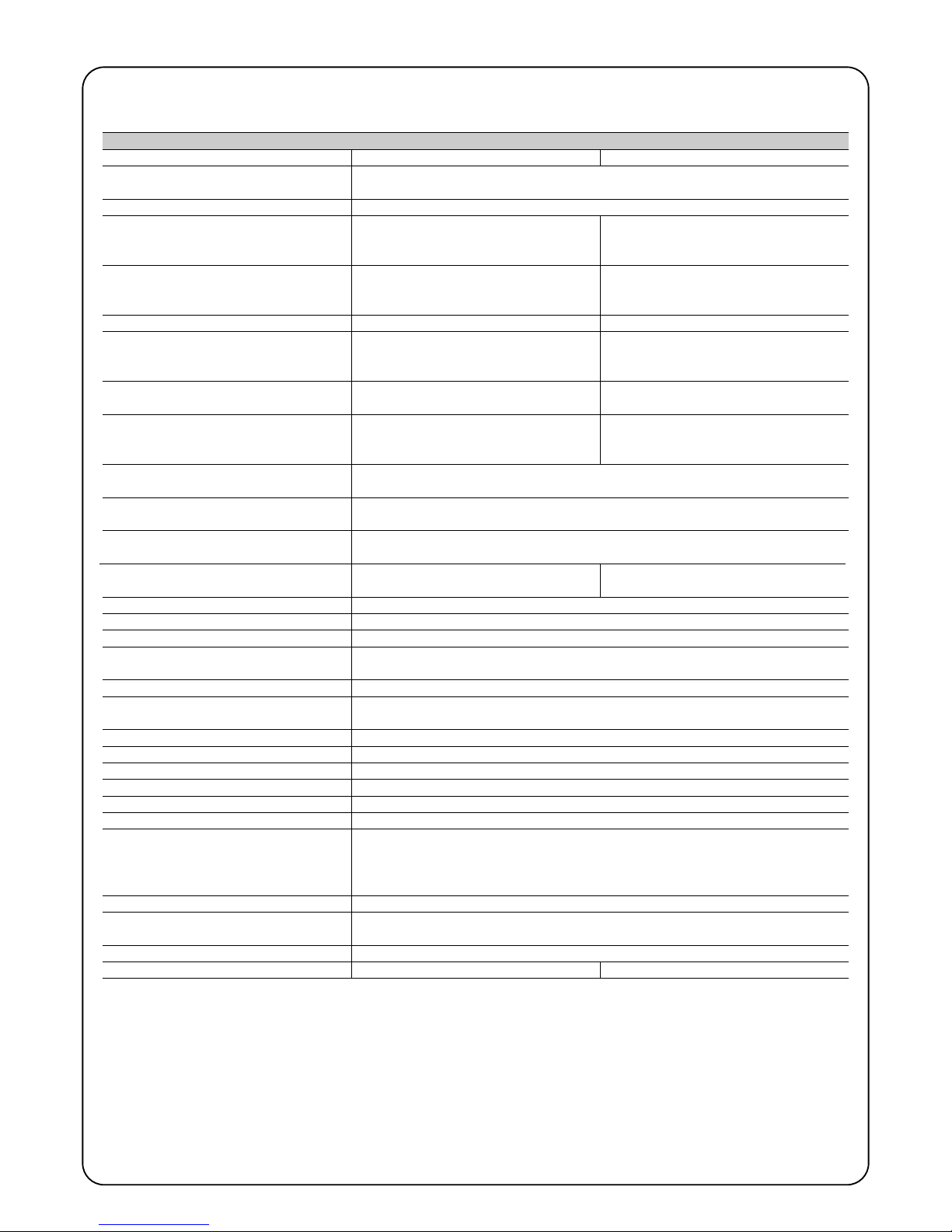
76
Utilisation en atmosphère particulièrement
acide ou saline ou potentiellement explosive
330 x 210 h 303; 11Kg 330 x 210 h 303; 13Kg
Dans le but d'améliorer ses produits, Nice S.p.a. se réserve le droit de modifier les caractéristiques techniques à tout moment et sans préavis, en garantissant dans tous les cas le bon fonctionnement et le type d'utilisation prévus.
Toutes les caractéristiques techniques se réfèrent à la température de 20°C (±5°C)
8) Caractéristiques techniques
Typologie
Modèle type
Caractéristiques techniques ROBUS
Opérateur électromécanique pour le mouvement automatique de portails coulissants
pour usage résidentiel avec logique électronique de commande incorporée
RB600 – RB600P RB1000 – RB1000P
Pignon Z: 15; Module: 4; Pas: 12,6 mm; Diamètre primitif: 60 mm
Couple maximum au démarrage correspon-
dant à la capacité de développer une force
pour mettre en mouvement le portail
18Nm
[600N]
27Nm
[900N]
Couple nominal correspondant à la capacité
de développer une force pour maintenir en
mouvement un portail
9Nm
[300N]
15Nm
[500N]
Vitesse au couple nominal
0,15m/s 0,14m/s
Vitesse à vide (la logique permet de programmer 6 vitesses égales à environ: 100,
85, 70, 55, 45, 30%)
0,31m/s 0,28m/s
Fréquence maximum des cycles de fonctionnement (au couple nominal)
100 cycles/jour (la logique limite les cycles au
maximum prévu dans les tableaux 2 et 3)
150 cycles/jour (la logique limite les cycles au
maximum prévu dans les tableaux 2 et 3)
Temps maximum de fonctionnement continu (au couple nominal)
7 minutes
(la logique limite les cycles au maximum
prévu dans les tableaux 2 et 3)
5 minutes
(la logique limite les cycles au maximum
prévu dans les tableaux 2 et 3)
Limites d'utilisation
Généralement ROBUS est en mesure d'automatiser des portails d'un poids ou d'une
longueur suivant les limites prévues dans les tableaux 2, 3 et 4.
Durabilité
Estimée entre 20.000 cycles et 250.000 cycles, suivant les conditions indiquées dans le
tableau 4
Puissance maximum absorbée au démarrage
[correspondant à Ampères]
515W [2,5A] [4,8A version /V1] 450W [2,3A] [4,4A version /V1]
Classe d'isolement 1 (la mise à la terre est nécessaire)
Alimentation de secours Avec accessoire en option PS124
Sortie clignotant Pour 2 clignotants LUCYB (Ampoule 12 V, 21 W).
Sortie BLUEBUS Une sortie avec charge maximum de 15 unités BlueBus
Sortie S.C.A.
pour 1 ampoule 24 V maximum 4 W (la tension de sortie peut varier de -30 à +50% et
peut commander également des petits relais)
Entrée STOP
Pour contacts normalement fermés, normalement ouverts ou à résistance constante 8,2KΩ; en
auto-apprentissage (une variation par rapport à l'état mémorisé provoque la commande “STOP”)
Entrée PP
Pour contacts normalement ouverts (la fermeture du contact provoque la commande P.P.)
Entrée OUVERTURE
Entrée FERMETURE
Pour contacts normalement ouverts (la fermeture du contact provoque la commande OUVERTURE)
Pour contacts normalement ouverts (la fermeture du contact provoque la commande FERMETURE)
Connecteur radio Connecteur “SM” pour récepteurs type SMXI ou SMXIS
Entrée ANTENNE Radio 52 Ω pour câble type RG58 ou similaires
Alimentation ROBUS 600 - 1000
Alimentation ROBUS 600 - 1000/V1
230 Vca (+10, -15%) 50/60 Hz
120 Vca (+10, -15%) 50/60 Hz
Fonctions programmables 8 fonctions de type ON-OFF et 8 fonctions réglables (voir tableaux 7 et 9)
Température de fonctionnement -20°C ÷ 50°C
Non
Indice de protection IP 44
Dimensions et poids
Fonctions en auto-apprentissage
Auto-apprentissage des dispositifs connectés à la sortie BlueBUS
Auto-apprentissage du type de dispositif de “STOP” (contact NO, NF ou résistance
8,2KΩ) Auto-apprentissage de la longueur du portail et calcul des points de ralentisse-
ment et ouverture partielle.

77
F
Félicitations pour avoir choisi un produit Nice pour votre
automatisation ! Nice S.p.A. produit des composants pour
l'automatisation de portails, portes, rideaux métalliques,
volets roulants et stores: opérateurs, logiques de commande, radiocommandes, clignotants, photocellules et
accessoires. Nice n'utilise que des matériaux et des usinages de qualité et par vocation, elle recherche des solutions innovantes qui simplifient au maximum l'utilisation de
ses appareils, très soignés sur le plan de la technique, de
l'esthétique et de l'ergonomie: dans la vaste gamme Nice,
votre installateur aura choisi sans aucun doute le produit
le plus adapté à vos exigences. Nice n'est toutefois pas le
producteur de votre automatisme qui est en effet le résultat d'un travail d'analyse, évaluation, choix des matériaux
et réalisation de l'installation, exécutée par votre installateur de confiance. Chaque automatisme est unique et seul
votre installateur possède l'expérience et la compétence
professionnelle nécessaires pour réaliser une installation
répondant à vos exigences, sûre et fiable dans le temps et
surtout, exécutée dans les règles de l'art et conforme par
conséquent aux normes en vigueur. Une installation d'automatisation est une belle commodité ainsi qu'un système
de sécurité valable; avec quelques attentions très simples,
elle est destinée à durer dans le temps. Même si l'automatisme en votre possession satisfait le niveau de sécurité requis par les normes, cela n'exclut pas la persistance
d'un “risque résiduel”, c'est-à-dire la possibilité de situations de danger dues généralement à une utilisation
inconsciente, voire erronée. C'est la raison pour laquelle
nous désirons vous donner quelques conseils sur les
comportements à adopter pour éviter tout inconvénient:
•Avant d'utiliser pour la première fois l'automa-
tisme, faites-vous expliquer par l'installateur l'origine
des risques résiduels et consacrez quelques minutes à la
lecture du manuel d'instructions et d'avertisse-
ments pour l'utilisateur qui vous est remis par l'installateur. Conservez le manuel pour pouvoir le consulter
pour n'importe quel doute futur et remettez-le à tout
nouveau propriétaire de l'automatisme.
•Votre automatisme est un équipement qui exé-
cute fidèlement vos commandes; une utilisation
inconsciente et incorrecte peut le rendre dangereux: ne
commandez pas le mouvement de l'automatisme si des
personnes, des animaux ou des objets se trouvent dans
son rayon d'action.
•Enfants: une installation d'automatisation garantit un
degré de sécurité élevé en empêchant avec ses systèmes de détection le mouvement en présence de personnes ou d'objets et en garantissant une activation toujours prévisible et sûre. Il est prudent toutefois de ne pas
laisser jouer les enfants à proximité de l'automatisme et
pour éviter les activations involontaires, de ne pas laisser
à leur portée les émetteurs qui commandent la
manœuvre: ce n'est pas un jeu!
•Anomalies: si vous notez une anomalie quelconque
dans le fonctionnement de l'automatisme, coupez l'ali-
mentation électrique de l'installation et procédez au
débrayage manuel. Ne tentez jamais de le réparer vousmême mais demandez l'intervention de votre installateur
de confiance: dans l'intervalle, l'installation peut fonctionner comme un système non automatisé, après avoir
débrayé l'opérateur suivant les indications données plus
loin.
•Maintenance: comme toutes les machines, votre auto-
matisme a besoin d'une maintenance périodique pour
pouvoir fonctionner le plus longtemps possible et en toute sécurité. Établissez avec votre installateur un plan de
maintenance périodique programmée; Nice conseille
une intervention tous les 6 mois pour une utilisation
domestique normale mais cette période peut varier en
fonction de l'intensité d'utilisation. Toute intervention de
contrôle, maintenance ou réparation doit être exécutée
exclusivement par du personnel qualifié.
•Même si vous estimez en être capable, ne modifiez pas
l'installation et les paramètres de programmation et de
réglage de l'automatisme: la responsabilité en incombe à
votre installateur.
•IL'essai de fonctionnement final, les maintenances périodiques et les éventuelles réparations doivent être documentés par la personne qui s'en charge et les documents doivent être conservés par le propriétaire de l'installation.
Les seules interventions que l'utilisateur peut et
doit effectuer périodiquement sont le nettoyage des verres
des photocellules et l'élimination des feuilles et des
cailloux qui pourraient bloquer l'automatisme. Pour empêcher que quelqu'un puisse actionner le portail, avant de
continuer, n'oubliez pas de débrayer l'automatisme
(comme nous l'avons décrit) et d'utiliser pour le nettoyage
uniquement un chiffon légèrement imbibé d'eau.
• Mise au rebut: à la fin de la vie de l'automatisme,
assurez-vous que le démantèlement est effectué par du
personnel qualifié et que les matériaux sont recyclés ou
mis au rebut en respectant les normes locales en
vigueur.
• En cas de ruptures ou absence d'alimentation
électrique: en attendant l'intervention de votre installateur (ou le retour du courant si l'installation est dépourvue de batterie tampon), l'installation peut être actionnée
comme n'importe quel autre système non automatisé.
Pour cela, il faut effectuer le débrayage manuel: cette
opération, qui est la seule pouvant être effectuée par
l'utilisateur de l'automatisme, a fait l'objet d'une étude
particulière de la part de Nice pour vous assurer toujours
une utilisation extrêmement simple et aisée, sans aucun
outil ou effort physique.
Instructions et recommandations destinées à l'utilisateur de l'opérateur ROBUS

78
Débrayage et mouvement manuel: avant d'effectuer cette opération, faire attention au fait que le débrayage ne
peut être fait que lorsque le portail est à l'arrêt.
Pour bloquer: effectuer les mêmes opérations dans le
sens contraire.
Commande avec sécurités hors service: si les dispositifs de sécurité ne fonctionnent pas correctement ou
sont hors service, on peut quand même commander le
portail.
• Actionner la commande du portail (avec la télécommande ou le sélecteur à clé). Si les sécurités donnent
leur accord le portail s'ouvrira normalement, autrement
le clignotant émet quelques clignotements mais la
manœuvre ne démarre pas (le nombre de clignotements dépend du motif pour lequel la manœuvre ne
démarre pas).
• Dans ce cas, dans les 3 secondes, il faut actionner de
nouveau la commande et la maintenir active.
• Au bout d'environ 2 s le mouvement du portail commencera en mode “homme mort”, c'est-à-dire que tant
que la commande est maintenue, le portail continue sa
manœuvre; dès que la commande est relâchée, le portail s'arrête.
Avec les sécurités hors service, il faut faire
réparer au plus tôt l'automatisme.
Remplacement de la pile de l'émetteur: si votre ins-
tallation est munie d'une radiocommande qui au bout
d'une certaine période présente des problèmes de fonctionnement ou ne fonctionne plus du tout, cela pourrait
dépendre tout simplement du fait que la pile est usagée
(suivant l'intensité d'utilisation, il peut s'écouler plusieurs
mois jusqu'à plus d'un an). Vous pouvez vérifier cet état
de chose si le voyant de confirmation de la transmission
est faible, s'il ne s'allume plus du tout ou s'il ne s'allume
qu'un bref instant. Avant de vous adresser à l'installateur,
essayez de remplacer la pile en utilisant celle d'un autre
émetteur qui fonctionne encore: si cette intervention remédie au problème, il vous suffit de remplacer la pile usagée
par une neuve du même type. Les piles contiennent des
substances polluantes: ne pas les jeter à la poubelle mais
suivre les règles de tri sélectif prévues par les réglementations locales.
Êtes-vous satisfait ? Si vous désirez équiper votre maison d'un nouvel automatisme, adressez-vous au même
installateur et à Nice. Vous serez sûr de bénéficier ainsi, en
plus du conseil d'un spécialiste et des produits les plus
évolués du marché, également du meilleur fonctionnement et de la compatibilité parfaite des différents automatismes installés. Nous vous remercions d'avoir lu ces
recommandations et nous espérons que votre nouvelle
installation vous donnera entière satisfaction: pour tout
besoin présent ou futur, adressez-vous en toute confiance
à votre installateur.
!
1 Faire coulisser le petit disque qui couvre
la serrure
2 Introduire la clé et la tourner dans le sens
des aiguilles d'une montre
3 Tirer la poignée de débrayage 4 Déplacer le portail à la main


80
Inhaltsverzeichnis: pag.
1 Hinweise 81
2 Produktbeschreibung und Einsatz 82
2.1 Einsatzgrenzen 82
2.2 Typische Anlage 84
2.3 Kabelliste 84
3 Installation 85
3.1 Vorprüfungen 85
3.2 Befestigung des Toröffners 85
3.3 Befestigung der Endschalterbügel in
den Versionen mit induktivem Endschalter 86
3.4 Installation der verschiedenen Vorrichtungen 87
3.5 Elektrische Anschlüsse 87
3.6 Beschreibung der elektrischen Anschlüsse 88
4 Endprüfungen und Anlassen 88
4.1 Auswahl der Richtung 88
4.2 Anschluss der Versorgung 88
4.3 Erlernung der Vorrichtungen 88
4.4 Erlernung der Torflügellänge 89
4.5 Überprüfung der Torbewegung 89
4.6 Bereits programmierte Funktionen 89
4.7 Funkempfänger 89
5 Abnahme und Inbetriebsetzung 89
5.1 Abnahme 90
5.2 Inbetriebsetzung 90
6 Wartung und Entsorgung 90
6.1 Wartung 90
6.2 Entsorgung 90
7 Weitere Auskünfte 91
7.1 Programmierungstasten 91
7.2 Programmierungen 91
7.2.1 Funktionen des ersten Niveaus
(ON-OFF-Funktionen) 91
7.2.2 Erstes Niveau - Programmierungen
(ON-OFF-Funktionen) 92
7.2.3 Funktionen des zweiten Niveaus
(einstellbare Parameter) 92
7.2.4 Zweites Niveau: Programmierungen
(einstellbare Parameter) 93
7.2.5 Erstes Niveau - Programmierungsbeispiel
(ON-OFF-Funktionen) 94
7.2.6 Zweites Niveau: Programmierungsbeispiel
(einstellbare Parameter) 94
7.3 Hinzufügen oder Entfernen von Vorrichtungen 94
7.3.1 BlueBUS 94
7.3.2 Eingang STOP 95
7.3.3 Photozellen 95
7.3.4 Lichtsensor FT210B 95
7.3.5 ROBUS in Modalität “Slave” 96
7.3.6 Erlernung sonstiger Vorrichtungen 97
7.4 Sonderfunktionen 97
7.4.1 Funktion “Öffnet Immer” 97
7.4.2 Funktion “Todmann” 97
7.4.3 Wartungsanzeige 97
7.5 Verbindung sonstiger Vorrichtungen 98
7.6 Probleme und deren Lösungen 99
7.6.1 Liste der Alarmhistorik 99
7.7 Diagnose und Anzeigen 99
7.7.1 Anzeigen durch die Blinkleuchte 100
7.7.2 Anzeigen durch die Steuerung 100
7.8 Zubehör 101
8 Technische Merkmale 102
Anweisungen und Hinweise für den Benutzer des
Toröffners ROBUS 103
Robus
600/600P
1000/1000P

81
D
1) Hinweise
Die vorliegenden Anweisungen enthalten wichtige Sicherheitsinformationen für die Installation; vor der Installation alle Anweisungen lesen. Dieses Handbuch auch für die Zukunft sorgfältig aufbewahren.
Unter Berücksichtigung der Gefahren, die bei Installation und Bedienung
von ROBUS auftreten können, muss die Installation für größte Sicherheit
unter voller Einhaltung von Gesetzen, Vorschriften und Verordnungen
erfolgen. In diesem Kapitel sind Hinweise allgemeiner Art gegeben; weitere wichtige Hinweise befinden sich in den Kapiteln “3.1 Vorprüfungen”;
“5 Abnahme und Inbetriebsetzung”.
Nach der neuesten europäischen Gesetzgebung, gehört
die Automatisierung einer Tür oder eines Tors zu den Verordnungen der Richtlinie 98/37/CE (Maschinenrichtlinie) und insbesondere zu den Vorschriften: EN 13241-1 (harmonisierte
Norm); EN 12445; EN 12453 und EN 12635, die es erlauben,
die Konformität mit der Maschinenrichtlinie zu erklären.
Weitere Auskünfte und Hinweise zur Analyse der Risiken und der Realisierung der Technischen Unterlagen stehen in www.niceforyou.com zur
Verfügung. Die vorliegende Anleitung ist nur für technisches Personal
bestimmt, das für die Installation qualifiziert ist. Mit Ausnahme der Anlage “Anweisungen und Hinweise für den Benutzer des Toröffners
ROBUS”, die der Installateur abtrennen muss, ist keine im vorliegenden
Heft enthaltene Information als interessant für den Endbenutzer zu
betrachten!
• Ein Gebrauch von ROBUS, der anders als in diesen Anweisungen vor-
gesehen ist, ist verboten. Ein unsachgemäßer Gebrauch kann Gefahren und Personen- oder Sachschäden verursachen.
• Vor der Installation ist die Risikoanalyse auszuführen, welche die Liste
der wesentlichen Sicherheitsanforderungen, vorgesehen in Anlage I
der Maschinenrichtlinie einschließt und die jeweiligen, angewendeten
Lösungen angeben muss.
Es wird daran erinnert, dass die Risikoanalyse eine der Unterlagen ist,
die Bestandteil der “Technischen Dokumentation” der Automatisierung
sind.
• Je nach Einsatzbedingungen und vorhandenen Gefahren prüfen, ob
weitere Vorrichtungen und Materialien erforderlich sind, um die Automatisierung mit ROBUS zu vervollständigen; berücksichtigt werden
müssen zum Beispiel Aufprallgefahr, Quetsch- und Mitnehmgefahr
usw. und sonstige Gefahren allgemein.
• Keine Änderungen an keinem Teil ausführen, falls nicht im vorliegenden
Handbuch vorgesehen. Vorgänge dieser Art können nur Betriebsstörungen verursachen. NICE lehnt jegliche Haftung für Schäden aufgrund geänderter Produkte ab.
• Während Installation und Gebrauch vermeiden, dass Festteile oder
Flüssigkeiten in die Steuerung und sonstige geöffnete Vorrichtungen
eindringen können; wenden Sie sich ggf. an den NICE Kundendienst;
der Gebrauch von ROBUS in solchen Situationen kann Gefahren verursachen.
• Der Automatismus darf erst verwendet werden, nachdem die Inbe-
triebsetzung ausgeführt wurde, wie in Punkt “5 Abnahme und Inbetriebsetzung” vorgesehen.
• Das Verpackungsmaterial muss unter voller Einhaltung der örtlichen
Vorschriften entsorgt werden.
• Wenn ein Defekt mit den im vorliegenden Handbuch gegebenen Infos
nicht beseitigt werden kann, wenden Sie sich bitte an den NICE Kundendienst.
• Wenn Automatikschalter oder Sicherungen ausgelöst werden, muss
vor ihrer Rückstellung der Defekt festgestellt und beseitigt werden.
• Vor dem Zugriff auf die Klemmen im Deckel von ROBUS, alle Kreisläu-
fe der Versorgung abtrennen; falls die Abtrennvorrichtung nicht sichtbar ist, ein Schild mit der Aufschrift: “ACHTUNG - WARTUNG IM
GANG” anbringen.
Besondere Hinweise über die Eignung dieses Produktes mit Bezugnahme auf die Richtlinie 98/37/CE (ex 89/392/CEE):
• Dieses Produkt wird als “Bestandteil einer Maschine” auf den Markt
gegeben und daher hergestellt, um in eine Maschine eingegliedert
oder mit anderen Maschinen zusammengebaut zu werden, mit dem
Zweck, “eine Maschine” gemäß der Richtlinie 98/37/CE nur in Kombination mit anderen Bestandteilen und auf die im vorliegenden Handbuch beschriebenen Arten und Weisen zu realisieren. Wie von der
Richtlinie 98/37/CE vorgesehen, wird darauf hingewiesen, dass die
Inbetriebsetzung des oben genannten Produktes erst gestattet ist,
nachdem die Maschine, in die dieses Produkt eingegliedert ist, als
konform mit der Richtlinie 98/37/CE gekennzeichnet und erklärt worden ist.
Besondere Hinweise über die Eignung dieses Produktes mit Bezugnahme auf die Niederspannungsrichtlinie 73/23/CEE und die spätere
Änderung 93/68/CEE:
• Dieses Produkt, falls für seinen Zweck eingesetzt und in den in der vorliegenden Anleitung vorgesehenen Konfigurationen und in Kombination mit den von Nice S.p.A. hergestellten Artikeln im Katalog entspricht
den Anforderungen der Niederspannungsrichtlinie. Die Übereinstimmung mit den Anforderungen könnte nicht garantiert sein, wenn das
Produkt in nicht vorgesehenen Konfigurationen oder mit anderen Produkten benutzt wird; der Gebrauch des Produktes in solchen Situationen ist untersagt, bis der die Installation Ausführende die Übereinstimmung mit den laut Richtlinie vorgesehenen Anforderungen überprüft
hat.
Besondere Hinweise über die Eignung dieses Produktes mit Bezugnahme auf die Richtlinie 89/336/CEE “Elektromagnetische Verträglichkeit”
und spätere Änderungen 92/31/CEE und 93/68/CE:
• dieses Produkt in den in der vorliegenden Anleitung vorgesehenen
Konfigurationen und in Kombination mit den von Nice S.p.A. hergestellten Artikeln im Katalog wurde unter den schwierigsten Einsatzbedingungen Tests der elektromagnetischen Verträglichkeit unterzogen.
Die elektromagnetische Verträglichkeit könnte nicht garantiert sein,
wenn das Produkt in nicht vorgesehenen Konfigurationen oder mit
anderen Produkten benutzt wird; der Gebrauch des Produktes in solchen Situationen ist untersagt, bis der die Installation Ausführende die
Übereinstimmung mit den laut Richtlinie vorgesehenen Anforderungen
überprüft hat.
!

82
Toröffner Typ RB600 RB600P RB1000 RB1000PP
Endschaltertyp elektromechanisch
induktiver Annäherungsschalter
elektromechanisch
induktiver Annäherungsschalter
Höchstlänge des Torflügels 8m 12m
Höchstgewicht des Torflügels 600Kg 1000Kg
Max. Anlaufdrehmoment 18Nm 27Nm
(entspricht einer Kraft von) (600N) (900N)
Motor und Transformator Motor 24Vcc Ø 77mm Motor 24Vcc Ø 115mm
Säulentransformator EI Ringtransformator
ROBUS ist eine Linie selbsthemmender elektromechanischer Toröffner für die Automatisierung von Schiebetoren. Die Toröffner verfügen
über eine elektronische Steuerung und einen Verbinder für den Empfänger der Fernbedienung SMXI oder SMXIS (Optionals). Die elektrischen Anschlüsse zu den externen Vorrichtungen sind dank der
“BlueBUS” Technologie, mit der mehrere Vorrichtungen mit nur 2
Drähten angeschlossen werden können, vereinfacht. ROBUS funktioniert mit elektrischer Energie; bei Stromausfall kann das Tor mit
einem speziellen Schlüssel entriegelt und von Hand bewegt werden,
oder es kann das Sonderzubehör Pufferbatterie PS124 benutzt werden, das die Durchführung einiger Bewegungen auch bei Stromausfall ermöglicht.
Zur Linie ROBUS gehören die Produkte, deren wichtigste Unterschiede in Tabelle 1 beschrieben sind.
Anmerkung: 1Kg = 9,81N daher, z. B.: 600N = 61 Kg
2) Produktbeschreibung und Einsatz
1
Tabelle 1: Vergleich der wichtigsten Merkmale der Toröffner ROBUS
2.1) Einsatzgrenzen
Die Leistungsdaten der Produkte der Linie ROBUS sind in Kapitel “8
Technische Merkmale” angegeben; sie ermöglichen als einzige Werte eine korrekte Bewertung der Eignung der Produkte.
Dank der strukturellen Merkmale sind die Produkte der Linie ROBUS
innerhalb der in den Tabellen 2, 3 und 4 angegebenen Grenzen für
Schiebetore geeignet.
Die effektive Eignung von ROBUS zur Automatisierung eines
bestimmten Schiebetors hängt von den Reibungen und anderen,
auch gelegentlichen Ereignissen ab, wie zum Beispiel Vorhandensein
von Eis, das die Torbewegung behindern könnte.
Für eine effektive Überprüfung muss die Kraft gemessen werden, die
notwendig ist, um das Tor auf der gesamten Lauflänge zu bewegen;
dann muss kontrolliert werden, dass dieselbe die Hälfte des “Nenndrehmoments” nicht überschreitet, der in Kapitel “8 Technische
Merkmale” angegeben ist (eine Toleranz von 50% wird empfohlen,
da schlechte Witterung die Reibungswerte erhöhen kann); weiterhin
sind die Angaben in den Tabellen 2 und 3 zu berücksichtigen, um die
Anzahl an Zyklen/Stunde, die aufeinanderfolgenden Zyklen und die
zulässige Höchstgeschwindigkeit festzulegen.
RB600, RB600P RB1000, RB1000P
Torflügellänge (m) max. Zyklen/Stunde max. aufeinanderfolgende Zyklen max. Zyklen/Stunde
max. aufeinanderfolgende Zyklen
Fino a 4 40 20 50 25
4 ÷ 6 25 13 33 16
6 ÷ 8 20 10 25 12
8 ÷ 10 --- --- 20 10
10 ÷ 12 --- --- 16 8
Tabelle 2: Grenzen in Abhängigkeit von der Torflügellänge
330mm 210mm
303mm
92mm

83
D
Aufgrund der Länge des Torflügels kann die Höchstzahl an Betriebszyklen pro Stunde und an aufeinanderfolgenden Zyklen bestimmt werden, wogegen man mit dem Gewicht den Reduzierungsprozentsatz der Zyklen und die zulässige Höchstgeschwindigkeit bestimmen kann;
wenn für ROBUS 1000 der Torflügel z.B. 5 m lang ist, wären 33 Zyklen/Stunde und 16 aufeinanderfolgende Zyklen möglich, wenn der Torflügel jedoch 700 kg wiegt, müssen diese um 50% reduziert werden; das Resultat wäre daher 16 Zyklen/Stunde und 8 aufeinanderfolgende
Zyklen, wogegen die zulässige Höchstgeschwindigkeit V4 schnell wäre. Um Überhitzungen zu vermeiden, sieht die Steuerung einen Bewegungsbegrenzer vor, der sich auf der Anstrengung des Motors und der Dauer der Zyklen beruht und bei Überschreitung der Höchstgrenze
anspricht. Der Bewegungsbegrenzer misst auch die Umgebungstemperatur und sorgt bei besonders hohen Temperaturen für eine weitere
Reduzierung der Bewegungen.
In Kapitel “8 Technische Merkmale” ist eine Schätzung der durchschnittlichen Lebensdauer des Produktes angegeben. Dieser Wert wird
durch die Beschwerlichkeitszahl (Summe aller Faktoren, die zum Verschleiß beitragen) beeinflusst, mit der die Bewegungen ausgeführt werden. Um diesen Wert zu schätzen, müssen alle Beschwerlichkeitszahlen in Tabelle 4 addiert werden, dann kann die geschätzte Lebensdauer mit dem Gesamtergebnis im Schaubild überprüft werden.
ROBUS 1000 erzielt zum Beispiel an einem 650 kg schweren und 5 m langen Tor, ausgestattet mit Photozellen und ohne andere Ermüdungselemente, eine Beschwerlichkeitszahl von 50% (30+10+10). Nach dem Schaubild ist die geschätzte Lebensdauer 80.000 Zyklen.
RB600, RB600P RB1000, RB1000P
Gewicht des Torflügels (kg) Prozentsatz an Zyklen Zulässige Prozentsatz an Zyklen Zulässige
Höchstgeschwindigkeit Höchstgeschwindigkeit
bis zu 200 100% V6 = sehr sehr schnell 100% V6 = sehr sehr schnell
200 ÷ 400 80 V5 = sehr schnell 90 V5 = sehr schnell
400 ÷ 500 60 V4 = schnell 75 V4 = schnell
500 ÷ 600 50 V3 = mittel 60 V4 = schnell
600 ÷ 800 --- --- 50 V3 = mittel
800 ÷ 900 --- --- 45 V3 = mittel
900 ÷ 1000 --- --- 40 V3 = mittel
Tabelle 3: Grenzen in Abhängigkeit vom Torflügelgewicht
Beschwerlichkeitszahl % Robus Lebensdauer in Zyklen
600 1000
Gewicht des Torflügels (kg)
bis zu 200 10 5
200 ÷ 400 30 10
400 ÷ 600 50 20
600 ÷ 700 --- 30
700 ÷ 800 --- 40
800 ÷ 900 --- 50
900 ÷ 1000 --- 60
Länge des Torflügels (m)
bis zu 4 10 5
4 ÷ 6 20 10
6 ÷ 8 35 20
8 ÷ 10 --- 35
10 ÷ 12 --- 50
Sonstige Ermüdungselemente
(zu berücksichtigen, wenn die Wahrscheinlichkeit,
dass sie sich ereignen, über 10% ist)
Umgebungstemperatur über 40°C oder unter 0°C
oder Feuchtigkeit über 80%
10 10
Vorhandensein von Staub oder Sand 15 15
Salzhaltige Umgebung 20 20
Unterbrechung der Bewegung durch Photozelle 15 10
Unterbrechung der Bewegung durch Halt 25 20
Geschwindigkeit schneller als “L4 = schnell“ 20 15
Aktivierter Anlauf 25 20
Beschwerlichkeitszahl insgesamt %:
Anmerkung: wenn die Beschwerlichkeitszahl 100% überschreitet, sind die Bedingungen über der akzeptierbaren Grenze; die Benutzung eines größeren Modells wird empfohlen.
Tabelle 4: Schätzung der Lebensdauer in Abhängigkeit von der Beschwerlichkeitszahl der Bewegungen
Beschwerlichkeitszahl %
Lebensdauer in Zyklen

84
2.2) Typische Anlage
In Abbildung 2 ist die typische Anlage einer Schiebetorautomatisierung mit ROBUS gezeigt.
2
1 Schlüsseltaster
2 Photozellen auf Standsäule
3 Photozellen
4 Feste Hauptschaltleiste (Optional)
5 Bewegliche Hauptschaltleiste
6 Endschalterbügel “Geöffnet”
7 Zahnstange
8 Feste Nebenschaltleiste (Optional)
9 Blinkleuchte mit eingebauter Antennea
10 ROBUS
11 Endschalterbügel “Geschlossen”
12 Bewegliche Nebenschaltleiste (Optional)
13 Funksender
2.3) Kabelliste
In der typischen Anlage in Abbildung 2 sind auch die Kabel angegeben, die zur Verbindung der verschiedenen Vorrichtungen erforderlich
sind; in Tabelle 5 sind die Merkmale der Kabel verzeichnet.
Die benutzten Kabel müssen für die jeweilige Installation geeignet sein; zum Beispiel wird ein Kabel des Typs
H03VV-F zum Verlegen in Innenräumen empfohlen, oder des Typs H07RN-F für Außenanwendungen.
!
Anmerkung 1: wenn das Versorgungskabel länger als 30m ist, muss ein Kabel mit größerem Querschnitt benutzt werden, z.B. 3x2,5mm
2
und eine Sicherheitserdung in der Nähe der Automatisierung ist erforderlich.
Anmerkung 2: wenn das “BLUEBUS” Kabel länger als 30 m bis max. 50 m ist, ist ein Kabel 2x1mm
2
erforderlich.
Anmerkung 3: die beiden Kabel 2x0,5mm
2
können mit nur einem Kabel 4x0,5mm2ersetzt werden.
Anmerkung 4: wenn mehr als eine Schaltleiste vorhanden ist, siehe das Kapitel “7.3.2 Eingang HALT” für die empfohlene Verbindung
Anmerkung 5: zur Verbindung der beweglichen Schaltleisten an Schiebetoren sind geeignete Vorrichtungen zu verwenden, welche die
Verbindung auch bei sich bewegendem Torflügel ermöglichen.
Anschluss Kabeltyp Zulässige Höchstlänge
A: Elektrische Versorgungsleitung Nr. 1 Kabel 3x1,5mm
2
30m (Anmerkung 1)
B: Blinkleuchte mit Antenne Nr. 1 Kabel 2x0,5mm
2
20m
Nr. 1 Abschirmkabel des Typs RG58 20m (kürzer als 5m wird empfohlen)
C: Photozellen Nr. 1 Kabel 2x0,5mm
2
30m (Anmerkung 2)
D: Schlüsseltaster Nr. 2 Kabel 2x0,5mm2(Anmerkung 3) 50m
E: Feste Schaltleisten Nr. 1 Kabel 2x0,5mm2(Anmerkung 4) 30m
F: Bewegliche Schaltleisten Nr. 1 Kabel 2x0,5mm2(Anmerkung 4) 30m (Anmerkung 5)
Tabelle 5: Kabelliste
2
43 38
10
2
6
11
7
9
13
1251
EC F
D
C
F
A
B

85
D
3.2) Befestigung des Toröffners
Falls die Befestigungsfläche bereits vorhanden ist, muss der Toröffner mit geeigneten Mitteln wie z.B. Spreizdübel direkt auf der Oberfläche befestigt werden. Andernfalls, zur Befestigung des Toröffners:
1. Für das Fundament eine entsprechend große Grube ausgraben,
mit Bezugnahme auf die Maße in Abbildung 3.
2. Ein oder mehrere Rohre zum Durchführen der Elektrokabel vor-
bereiten, gemäß Abbildung 4.
3. Die beiden Spreizbeine an die Fundamentplatte montieren; hier-
bei eine Mutter unter und eine über der Platte anbringen; die Mutter unter der Platte muss wie in Abbildung 5 angeschraubt wer
den, so dass das Gewindeteil ca. 25÷35mm über der Platte herausragt.
4. Den Beton eingießen und die Fundamentplatte bevor der Beton
hart wird nach den Maßen in Abbildung 3 darin anbringen und
prüfen, dass sie parallel zum Torflügel und einwandfrei nivelliert
ist. Warten, bis der Beton ganz trocken ist.
5. Die beiden Muttern oben an der Platte abschrauben, dann den
Toröffner darauf legen und prüfen, dass er zum Torflügel ganz
parallel ist, dann die beiden Muttern und die Unterlegscheiben
etwas anschrauben, wie in Abbildung 7 gezeigt.
Die Installation von ROBUS muss von qualifiziertem Personal unter genauester Beachtung der Gesetze, Vorschriften und
Verordnungen und der Angaben in den vorliegenden Anweisungen ausgeführt werden.
!
3) Installation
3.1) Vorprüfungen
Vor der Installation von ROBUS müssen folgende Kontrollen ausgeführt werden:
• Prüfen, dass das gesamte benutzte Material in bestem Zustand,
für den Einsatz geeignet und mit den Vorschriften konform ist.
• Prüfen, dass die Struktur des Tors so ist, dass es automatisiert
werden kann.
• Prüfen, dass sich Gewicht und Abmessungen des Torflügels innerhalb der Einsatzgrenzen in Kapitel “2.1 Einsatzgrenzen” befinden.
• Durch Vergleich mit den Werten in Kapitel “8 Technische Merkmale” prüfen, dass die zur Bewegung des Torflügels notwendige Kraft
kleiner als die Hälfte des “maximalen Drehmoments” ist, und dass
die Kraft, die notwendig ist, um den Torflügel in Bewegung zu halten, kleiner als die Hälfte des “Nenndrehmoments” ist; eine Toleranz der Kräfte von 50% wird empfohlen, da schlechte Witterung
die Reibungswerte erhöhen kann.
• Prüfen, dass entlang dem gesamten Lauf des Tors sowohl in
Schließung als auch in Öffnung keine größeren Reibungen anliegen.
• Prüfen, dass der Torflügel nicht ausgleiten und nicht aus den
Führungen treten kann.
• Die Robustheit der mechanischen Überlaufanschläge kontrollieren
und prüfen, dass keine Verformungen erfolgen, auch wenn der
Torflügel heftig auf diese aufprallen sollte.
• Prüfen, dass der Torflügel im Gleichgewicht ist: er darf sich nicht
bewegen, wenn er in beliebiger Stellung stehen bleibt.
• Prüfen, dass sich der Bereich, in dem der Toröffner befestigt wird,
nicht überschwemmt werden kann; den Toröffner ggf. über dem
Boden installieren.
• Prüfen, dass die Entriegelung und eine leichte und sichere Bewegung von Hand des Torflügels im Befestigungsbereich des Toröffners möglich sind.
• Prüfen, ob sich die Befestigungsstellen der verschiedenen Vorrichtungen in stoßgeschützten Bereichen befinden und ob die Oberflächen ausreichend solide sind.
• Elemente des Automatismus sollten nicht in Wasser oder andere
Flüssigkeit getaucht werden.
•
ROBUS nicht in der Nähe von Wärmequellen oder Flammen oder in EXgefährdeter, salz- oder säurehaltiger Umgebung halten; dies kann Schäden und Betriebsstörungen an ROBUS sowie Gefahren verursachen.
• Sollte der Torflügel eine Eingangstür haben oder sich eine Tür im
Bewegungsbereich des Torflügels befindet, ist sicher zu stellen,
dass diese den normalen Lauf des Tors nicht behindert; ggf. für ein
geeignetes Verblockungssystem sorgen.
• Die Steuerung an eine elektrische Versorgungsleitung mit Sicherheitserdung anschließen.
•
Die elektrische Versorgungsleitung muss durch eine geeignete magnetothermische Vorrichtung und Differentialschalter geschützt sein.
• Weiterhin muss eine Abtrennvorrichtung der Stromversorgung (mit
Überspannungsklasse III bzw. Abstand zwischen den Kontakten
von mindestens 3,5 mm) oder ein gleichwertiges System wie z.B.
Steckdose und Stecker vorhanden sein. Sollte sich die Abtrennvorrichtung der Stromversorgung nicht in der Nähe der Automatisierung befinden, muss sie über ein Absperrsystem verfügen, dass
vor einem unbeabsichtigten oder nicht genehmigten erneuten
Anschluss schützt.
3
4
5
6
25÷35
7
192
330 0÷50
0÷50 330
192
0÷10
0÷10

86
3.3) Befestigung der Endschalterbügel in den Versionen mit induktivem Annäherungsschalter
Um zu vermeiden, dass das Gewicht des Torflügels auf dem
Toröffner liegt, muss zwischen Zahnstange und Ritzel ein Spiel
von 1÷2 vorhanden sein, wie in Abbildung 10.
8.
Den Torflügel gleiten lassen und zur Befestigung der anderen Zahnstangenteile immer Bezug auf das Ritzel nehmen.
9.
Das überschüssige Teil am Ende der Zahnstange wegschneiden.
10.
Den Torflügel mehrmals öffnen und schließen und dabei prüfen,
dass die Zahnstange gefluchtet auf dem Ritzel gleitet. Die Nichtfluchtung darf max. 5 mm sein und in der gesamten Länge muss ein
Spiel von 1÷2 mm zwischen Ritzel und Zahnstange vorhanden sein.
11.
Die Befestigungsmuttern des Toröffners energisch anziehen, so
dass dieser gut am Boden befestigt ist; die Befestigungsmuttern mit
den dazu vorgesehenen Kappen bedecken, gemäß Abbildung 11.
12.
Die Endschalterbügel wie hier folgend beschrieben befestigen (für
die Versionen RB600P und RB1000P, die Bügel wie in Par. “3.3
Befestigung der Endschalterbügel für die Versionen mit induktivem
Annäherungsschalter” befestigen):
• Das Tor von Hand öffnen, so dass es mindestens 2 – 3 cm
Abstand vom mechanischen Endanschlag hat.
• Den Bügel in Öffnungsrichtung auf der Zahnstange gleiten lassen,
bis der Endschalter auslöst. Den Bügel dann mindestens 2 cm
vorschieben und mit den jeweiligen Stiftschrauben an der Zahnstange befestigen, wie in Abbildung 12.
• Dasselbe für den Endschalter in Schließung ausführen.
13. Den Toröffner blockieren, wie in “Entriegelung und Bewegung von
Hand” im Kapitel “Anweisungen und Hinweise für den Benutzer”
angegeben.
!
8 9 10
11 12
Falls die Zahnstange bereits vorhanden ist, nach der Befestigung
des Toröffners die Verstellstifte betätigen, wie in Abbildung 8 gezeigt,
um das Ritzel von ROBUS auf die richtige Höhe zu bringen und
1÷2mm Spiel von der Zahnstange zu lassen. Andernfalls, für die
Befestigung der Zahnstange wie folgt vorgehen:
6. Den Toröffner entriegeln, wie in “Entriegelung und Bewegung von
Hand” im Kapitel “Anweisungen und Hinweise für den Benutzer
des Toröffners ROBUS” angegeben.
7. Den Torflügel ganz öffnen, das erste Teil der Zahnstange auf das
Ritzel legen und prüfen, dass der Anfang der Zahnstange mit
dem Anfang des Torflügels übereinstimmt, gemäß Abbildung 9.
Prüfen, dass ein Spiel von 1÷2 zwischen Ritzel und Zahnstange
vorhanden ist, dann die Zahnstange mit geeigneten Mitteln am
Torflügel befestigen.
1÷2
Für die Versionen RB600P und RB1000P, die induktive Annäherungsschalter anwenden, müssen die Endschalterbügel wie hier folgend beschrieben befestigt werden.
1. Das Tor von Hand öffnen, so dass es mindestens 2 – 3 cm
Abstand vom mechanischen Endanschlag hat.
2. Den Bügel in Öffnungsrichtung auf der Zahnstange gleiten lassen,
bis sich die entsprechende LED ausschaltet – siehe Abbildung
13. Den Bügel dann mindestens 2 cm vorschieben und mit den
jeweiligen Stiftschrauben an der Zahnstange befestigen.
3. Das Tor von Hand schließen, so dass es mindestens 2 – 3 cm
Abstand vom mechanischen Endanschlag hat.
4. Den Bügel in Schließrichtung auf der Zahnstange gleiten lassen,
bis sich die entsprechende LED ausschaltet. Den Bügel dann
mindestens 2 cm vorschieben und mit den jeweiligen Stiftschrauben an der Zahnstange befestigen.
Achtung: am induktiven Annäherungsendschalter beträgt
der optimale Abstand des Bügels von 3 bis 8 mm, wie auf
Abbildung 14 gezeigt.
!
13
14
3÷8

87
D
3.5) Elektrische Anschlüsse
Alle elektrischen Anschlüsse müssen ohne Spannung zur Anlage
und mit abgetrennter, eventueller Pufferbatterie ausgeführt werden.
1. Um den Schutzdeckel zu entfernen und Zugang zur elektronischen
Steuerung von ROBUS zu erhalten, muss die Schraube seitlich entfernt und der Deckel nach oben herausgezogen werden.
2. Die Gummimembrane entfernen, mit der das Loch für den Kabel-
durchgang geschlossen ist, und alle Verbindungskabel zu den
verschiedenen Vorrichtungen einführen, dabei die Kabel 20÷30
länger als notwendig lassen. Siehe die Tabelle 5 für den Kabeltyp
und die Abbildung 2 für die Anschlüsse.
3. Alle Kabel, die in den Toröffner eintreten, mit einer Schelle verei-
nen. Die Schelle gleich unter dem Loch für den Kabeldurchgang
anbringen. An der Gummimembrane ein Loch schneiden, dessen
Durchmesser etwas kleiner als der Durchmesser der vereinten
Kabel ist, dann die Membrane entlang den Kabeln bis zur Schelle einstecken und die Membrane wieder in ihren Sitz am Loch des
Kabeldurchgangs einspannen. Die Kabel gleich über der Membrane mit einer zweiten Schelle vereinen.
4.
Das Versorgungskabel an der jeweiligen Klemme anschließen, wie in Abbildung
15 gezeigt, dann das Kabel am ersten Kabelhaltering mit einer Schelle blockieren.
5.
Die Anschlüsse der anderen Kabel nach dem Plan in Abbildung 17 aus-
führen. Der Einfachheit wegen können die Klemmen abgezogen werden.
6. Die vereinten Kabel nach Beendigung der Anschlüsse mit Schellen am zweiten Kabelhaltering blockieren; das überschüssige Teil
des Antennekabels muss mit einer weiteren Schelle an den anderen Kabeln blockiert werden, gemäß Abbildung 16.
!
3.4) Installation der verschiedenen Vorrichtungen
Die Installation der anderen vorgesehenen Vorrichtungen nach den jeweiligen Anweisungen ausführen. In Paragraph “3.5 Beschreibung der
elektrischen Anschlüsse” und in Abbildung 2 die Vorrichtungen überprüfen, die an ROBUS angeschlossen werden können.
15
17
16
Für den Anschluss von 2 Motoren an gegenüber liegenden Torflügeln siehe den Par. “7.3.5 ROBUS in Modalität Slave”.
LUCYB
S.C.A.
MOFB MOSE
OPEN CLOSE

88
3.6) Beschreibung der elektrischen Anschlüsse
Dieser Paragraph enthält eine kurze Beschreibung der elektrischen
Anschlüsse; für weitere Auskünfte wird auf Par. “7.3 Hinzufügen oder
Entfernen von Vorrichtungen” verwiesen.
FLASH: Ausgang für eine oder zwei Blinkleuchten des Typs
“LUCYB” oder ähnliche mit nur einer 12V max. 21W Glühbirne.
S.C.A.: Ausgang “Leuchtmelder Tor Geöffnet”; angeschlossen werden kann ein 24V max. 4W Leuchtmelder. Kann auch für andere
Funktionen programmiert werden – siehe Par. “7.2.3 Funktionen
zweiten Niveaus”
BLUEBUS: an dieser Klemme können kompatible Vorrichtungen
angeschlossen werden; alle Vorrichtungen werden mit nur zwei Leitern, auf denen sowohl die Stromversorgung als auch die Kommunikationssignale übermittelt werden, parallel geschaltet. Weitere Auskünfte über BlueBUS sind in Par. “7.3.1 BlueBUS” enthalten.
STOP: Eingang für Vorrichtungen, welche die laufende Bewegung
blockieren oder ggf. anhalten; mit entsprechenden Maßnahmen
können am Eingang “gewöhnlich geschlossene” und “gewöhnlich
geöffnete” Kontakte oder Vorrichtungen mit gleichbleibendem
Widerstand angeschlossen werden. Weitere Auskünfte über STOP
sind in Par. “7.3.2 Eingang STOP” enthalten.
P. P. : Eingang für Vorrichtungen, welche die Bewegung in Modalität
Schrittbetrieb steuern; es können “gewöhnlich geöffnete” Kontakte
angeschlossen werden.
OPEN: Eingang für Vorrichtungen, die nur eine Öffnungsbewegung
steuern; es können “gewöhnlich geöffnete” Kontakte angeschlossen
werden.
CLOSE: Eingang für Vorrichtungen, die nur eine Schließbewegung
steuern; es können “gewöhnlich geöffnete” Kontakte angeschlossen
werden.
ANTENNA: Eingang für den Anschluss der Antenne für Funkempfänger (die Antenne ist in LUCY B eingebaut).
Vor Beginn der Überprüfung und des Anlassens der Automatisierung sollte das Tor auf Laufhälfte verschoben werden, so dass es sich in Öffnung und Schließung frei bewegen kann.
4) Endprüfungen und Anlassen
4.1) Auswahl der Richtung
Je nachdem, wie der Toröffner am Torflügel angebracht ist, muss die
Richtung der Öffnungsbewegung gewählt werden. Falls sich der
Torflügel zum Öffnen nach links bewegen muss, den Wählschalter
nach links verschieben, wie in Abbildung 18, falls er sich zum Öffnen
nach rechts bewegen muss, den Wählschalter nach rechts verschieben, wie in Abbildung 19.
18
19
4.2) Anschluss der Versorgung
Der Anschluss der Versorgung zu ROBUS muss von
erfahrenem Fachpersonal mit den erforderlichen Kenntnissen und unter voller Einhaltung von Gesetzen, Vorschriften und Verordnungen ausgeführt werden.
Sobald ROBUS mit Spannung versorgt ist, sollten einige einfache
Überprüfungen ausgeführt werden:
1. Prüfen, ob die BlueBUS-LED regelmäßig einmal pro Sekunde
blinkt.
2. Prüfen, ob auch die LEDs an den Photozellen (sowohl an TX als
auch an RX) blinken; wie die LEDs blinken, hat keine Bedeutung
und hängt von anderen Faktoren ab.
3. Prüfen, ob die am Ausgang FLASH angeschlossene Blinkleuchte
und der am Ausgang S.C.A. angeschlossene Leuchtmelder ausgeschaltet sind.
Sollte all dies nicht der Fall sein, muss die Versorgung zur Steuerung
unverzüglich ausgeschaltet werden, dann die elektrischen Anschlüsse genauer kontrollieren.
Weitere nützliche Auskünfte über die Fehlersuche und die Diagnose
befinden sich in Kapitel “7.6 Probleme und deren Lösung”.
!
4.3) Erlernung der Vorrichtungen
Nach dem Anschluss der Versorgung muss die Steuerung die an den Eingängen BlueBUS und STOP angeschlossenen Vorrichtungen erkennen. Vor dieser Phase blinken die LEDs L1 und L2 und geben somit an, dass die Erlernung der Vorrichtungen ausgeführt werden muss.
Die Erlernphase der angeschlossenen Vorrichtungen kann jederzeit auch nach der Installation wiederholt werden, wenn zum Beispiel eine
Vorrichtung hinzugefügt wird; für die Durchführung einer neuen Erlernung siehe Par. “7.3.6 Erlernung sonstiger Vorrichtungen”.
1. Auf die Tasten [▲] und [Set] drücken und gedrückt halten
2. Die Tasten loslassen, wenn die LEDs L1 und L2 sehr schnell zu blinken beginnen (nach ca. 3 Sekunden)
3. Ein paar Sekunden warten, bis die Steuerung die Erlernung der Vorrichtungen beendet.
4. Am Ende der Erlernung muss die LED STOP leuchtend bleiben; die LEDs L1 und L2 werden sich aus-
schalten (eventuell werden L3 und L4 zu blinken beginnen)
20

89
D
4.4) Erlernung der Torflügellänge
Nach der Erlernung der Vorrichtungen werden die LEDs L3 und L4 zu blinken beginnen. Das bedeutet, dass die Steuerung nun die Länge
des Torflügels erkennen muss (Abstand vom Endschalter in Schließung bis zu jenem in Öffnung). Dieses Maß ist für die Berechnung der Stellen notwendig, an denen die Verlangsamung und die Teilöffnung erfolgen soll.
Sollte all dies nicht der Fall sein, muss die Versorgung zur Steuerung unverzüglich ausgeschaltet werden, dann die elektrischen Anschlüsse
genauer kontrollieren. Weitere nützliche Auskünfte befinden sich in Kapitel “7.6 Probleme und deren Lösung”.
1. Auf die Tasten [▼] und [Set] drücken und gedrückt halten
2. Die Tasten loslassen, wenn die Bewegung beginnt (nach ca. 3s)
3. Prüfen, dass die laufende Bewegung eine Öffnungsbewegung ist, andernfalls auf Taste [Stop] drücken
und Punkt “4.1 Auswahl der Richtung” genauer kontrollieren; dann ab Punkt 1 wiederholen.
4. Warten, bis die Steuerung die Öffnungsbewegung bis zum Endschalter in Öffnung beendet; gleich danach
wird eine Schließbewegung beginnen.
5. Warten, bis die Steuerung die Schließbewegung beendet.
4.5) Überprüfung der Torbewegung
Nach der Erlernung der Torflügellänge sollten einige Bewegungen
ausgeführt werden, um zu prüfen, ob sich das Tor richtig bewegt.
1. Auf Taste [Open] drücken, damit eine Öffnungsbewegung
erfolgt; prüfen, ob sich das Tor regelmäßig und ohne Geschwindigkeitsschwankungen öffnet; erst wenn sich das Tor zwischen
70 und 50 cm vom Endschalter in Öffnung befindet, muss es verlangsamen und aufgrund der Auslösung des Endschalters 2÷3cm
vor dem mechanischen Endanschlag in Öffnung anhalten.
2. Auf Taste [Close] drücken, damit eine Schließbewegung erfolgt;
prüfen, ob sich das Tor regelmäßig und ohne Geschwindigkeitsschwankungen schließt; erst wenn sich das Tor zwischen 70 und
50 cm vom Endschalter in Schließung befindet, muss es verlang
samen und aufgrund der Auslösung des Endschalters 2÷3cm vor
dem mechanischen Endanschlag in Schließung anhalten.
3. Während der Bewegung prüfen, ob die Blinkleuchte in Abständen
von 0,5 Sekunden (0,5 Sek. ein, 0,5 Sek. aus) blinkt. Falls
vorhanden, auch das Blinken des an Klemme S.C.A. angeschlossenen Leuchtmelders überprüfen: langsames Blinken beim Öffnen, schnell beim Schließen.
4. Mehrere Öffnungs- und Schließbewegungen ausführen, um eventuelle Montage- und Einstellfehler oder sonstige Störungen wie
zum Beispiel stärkere Reibungen festzustellen.
5. Prüfen, ob Toröffner ROBUS, Zahnstange und Endschalterbügel
gut und stabil befestigt sind und auch plötzlichen Beschleunigungen oder Verlangsamungen der Torbewegung widerstehen.
4.6) Bereits programmierte Funktionen
Die Steuerung von ROBUS verfügt über einige programmierbare
Funktionen. Werkseitig sind diese Funktionen so konfiguriert, dass
sie den Bedarf der meisten Automatisierungen zufrieden stellen
müssten; sie können aber über ein entsprechendes Programmie
rungsverfahren jederzeit geändert werden – siehe hierzu Paragraph
“7.2 Programmierungen”.
21
4.7) Funkempfänger
Für die Fernsteuerung von ROBUS ist an der Steuerung der Steckverbinder SM für Funkempfänger des Typs SMXI oder SMXIS (Optionals) vorgesehen. Für weitere Auskünfte wird auf die Anweisungen des Funkempfängers verwiesen. Zum Einstecken des Funkempfängers, den in Abbildung 22 gezeigten Vorgang ausführen. In Tabelle 6 ist beschrieben, welche Befehle welchen Funkempfängerausgängen zugeordnet sind:
22
Ausgang Nr. 1 Befehl “P.P.” (Schrittbetrieb)
Ausgang Nr. 2 Befehl “Gehflügelöffnung”
Ausgang Nr. 3 Befehl “Öffnet”
Ausgang Nr. 4 Befehl “Schließt”
Tabelle 6: mit Sender erteilte Befehle
Um höchste Sicherheit zu gewährleisten, sind dies die wichtigsten
Schritte bei der Realisierung der Automatisierung. Die Abnahme
kann auch als regelmäßige Überprüfungen der Bestandteile des
Automatismus verwendet werden.
Die Abnahme der gesamten Anlage muss von erfahrenem Fachpersonal ausgeführt werden, das die erforderlichen Tests je nach vorhandenem Risiko auszuführen und
die Einhaltung des von Gesetzen, Vorschriften und Verordnungen Vorgesehenen zu überprüfen hat, und insbesondere alle Anforderungen der Norm EN12445, die Testmethoden zur Überprüfung von Torautomatismen festlegt.
!
5) Abnahme und Inbetriebsetzung

90
5.1) Abnahme
Für jedes einzelne Element des Automatismus wie zum Beispiel
Schaltleisten, Photozellen, Notstops usw. ist eine spezielle Abnahmephase erforderlich; für diese Vorrichtungen sind die Verfahren in
den jeweiligen Anleitungen auszuführen. Für die Abnahme von
ROBUS ist folgende Arbeitssequenz durchzuführen:
1. Prüfen, ob alles in der vorliegenden Anweisung und insbesondere
das in Kapitel 1 “Hinweise” angegebene genauestens eingehalten ist.
2. Den Toröffner entriegeln, wie in “Entriegelung und Bewegung von
Hand” im Kapitel “Anweisungen und Hinweise für den Benutzer
des Toröffners ROBUS” angegeben.
3. Prüfen, ob es möglich ist, den Torflügel in Öffnung und Schließung
mit einer Kraft nicht über 390N (ca. 40 kg) von Hand zu bewegen
4. Den Toröffner blockieren.
5. Die vorgesehenen Steuervorrichtungen (Schlüsseltaster, Steuerta-
sten oder Funksender) verwenden, die Schließung und Öffnung
des Tors testen und prüfen, ob das Verhalten wie vorgesehen ist.
6. Den korrekten Betrieb aller Sicherheitsvorrichtungen der Anlage
einzeln überprüfen (Photozellen, Schaltleisten, Notstops usw.)
und prüfen, ob das Verhalten wie vorgesehen ist. Bei jeder Auslösung einer Vorrichtung wird die BlueBUS-LED an der Steuerung
zweimal schneller blinken und so bestätigen, dass die Steuerung
das Ereignis erkannt hat.
7. Falls die durch die Torbewegung verursachten Gefahren mittels
Begrenzung der Aufprallkraft abgesichert worden sind, muss die
Kraft nach den Verordnungen der Vorschrift EN 12445 gemessen
werden. Falls die “Geschwindigkeitsregelung” und die Kontrolle
der “Motorkraft” als Hilfsmittel für das System zur Aufprallkraftreduzierung benutzt werden, die Einstellungen testen und definieren, mit welcher Einstellung die besten Ergebnisse erzielt werden.
5.2) Inbetriebsetzung
Die Inbetriebsetzung darf erst erfolgen, nachdem alle Abnahmephasen von ROBUS sowie der anderen Vorrichtungen erfolgreich beendet sind. Eine teilweise oder vorübergehende Inbetriebsetzung ist
unzulässig.
1. Die technischen Unterlagen der Automatisierung zusammenstellen
und diese mindestens 10 Jahre lang aufbewahren. Sie müssen
mindestens umfassen: Gesamtzeichnung der Automatisierung,
Schaltplan mit den elektrischen Anschlüssen, Risikoanalyse und
jeweilige angewendete Lösungen, Konformitätserklärung des Herstellers für alle benutzten Vorrichtungen (für ROBUS die anliegende
“CE-Konformitätserklärung” verwenden), Kopie der Bedienungsanweisungen und des Wartungsplans der Automatisierung.
2. Am Tor ein Schild mit mindestens folgenden Daten anbringen: Automatisierungstyp, Name und Adresse des Herstellers (Verantwortlicher
der “Inbetriebsetzung”), Seriennummer, Baujahr und CE-Markierung.
3. In Tornähe auf bleibende Art ein Etikett oder ein Schild befestigen,
dass die Angaben zur Durchführung der Entriegelung und der
Bewegung von Hand enthält.
4. Die Konformitätserklärung der Automatisierung anfertigen und
dem Inhaber aushändigen.
5. Realizzare e consegnare al proprietario il manuale di “Istruzioni ed
avvertenze per l'uso dell'automazione”.
6. Den Wartungsplan der Automatisierung anfertigen und dem Inhaber aushändigen. Er muss alle Wartungsvorschriften der einzelnen
Vorrichtungen enthalten.
7. Vor der Inbetriebsetzung des Automatismus, den Inhaber auf
geeignete Weise und schriftlich (z.B. in den “Anweisungen und
Hinweise für die Bedienung der Automatisierung” über die noch
vorhandenen Gefahren und Risiken informieren.
Dieses Kapitel enthält die Informationen zur Anfertigung des Wartungsplans und für die Entsorgung von ROBUS.
6) Wartung und Entsorgung
6.1) Wartung
Um das Sicherheitsniveau gleichbleibend zu halten und die längste
Dauer der ganzen Automatisierung zu garantieren, ist eine regelmäßige Wartung erforderlich; hierzu verfügt ROBUS über einen
Bewegungszähler und ein Meldesystem “Wartung erforderlich” – siehe Par. “7.4.3 Wartungsmeldung”.
Die Wartung muss unter genauester Einhaltung der im
vorliegenden Handbuch verzeichneten Sicherheitsbestimmungen und der Verordnungen der gültigen Gesetze und
Vorschriften ausgeführt werden.
Sollten Vorrichtungen vorhanden sein, die anders als ROBUS sind,
das in ihrem Wartungsplan vorgesehene ausführen.
1. Für ROBUS ist max. innerhalb von 6 Monaten oder 20.000
Bewegungen nach der vorherigen Wartung eine programmierte
Wartung erforderlich:
2. Alle elektrischen Versorgungsquellen, inklusive eventuelle Pufferbatterien abtrennen.
3. Die Verschlechterung aller Materialen der Automatisierung überprüfen, mit besonderer Achtung auf Erosions- oder Roststellen an
strukturellen Teilen; Teile, die nicht genügend Garantie geben,
müssen ersetzt werden.
4.
Den Verschleiß der Bewegungselemente überprüfen, wie Ritzel, Zahnstange und alle Torflügelteile; abgenutzte Teile müssen ersetzt werden.
5.
Die elektrischen Versorgungsquellen wieder anschließen und alle in Punkt
“5.1 Abnahme” vorgesehenen Tests und Überprüfungen ausführen.
!
6.2) Entsorgung
ROBUS besteht aus verschiedenen Stoffen, von denen einige recycled
werden können (Stahl, Aluminium, Plastik, Elektrokabel), andere müssen
dagegen entsorgt werden (Batterien und elektronische Karten).
Einige elektronische Komponenten und die Batterien
könnten Schadstoffe enthalten: nicht in die Umwelt
geben. Informieren Sie sich über die Recycling- oder Entsorgungssysteme und halten Sie sich an die örtlich gültigen Vorschriften.
1. Die Stromversorgung vom Automatismus und die eventuelle Puf-
ferbatterien abtrennen.
2. Alle Vorrichtungen und Zubehörteile demontieren. Hierzu das in Kapitel “3 Installation” beschriebene Verfahren umgekehrt ausführen.
3. Soweit möglich, Teile trennen, die verschiedenartig recycled oder
entsorgt werden können, zum Beispiel Metall von Plastik, elektronische Karten, Batterien, usw.
4. Sortieren und die so getrennten Werkstoffe örtlichen Wiederverwertungs- und Entsorgungsstellen anvertrauen.
!

91
D
In diesem Kapitel werden die Möglichkeiten für die Programmierung, eine persönliche Gestaltung, die Diagnose und die Fehlersuche an ROBUS behandelt.
7) Weitere Auskünfte
Open Mit Taste “OPEN” kann dem Tor ein Öffnungsbefehl erteilt werden
▲ oder sie dient zur Verschiebung des Programmierungspunktes nach oben.
Stop Mit Taste “STOP” kann die Bewegung angehalten werden; falls länger
Set
als 5 Sekunden gedrückt, ermöglicht sie den Zugriff auf die Programmierung.
Close Mit Taste “CLOSE” kann dem Tor ein Schließbefehl erteilt werden oder
▼ sie dient zur Verschiebung des Programmierungspunktes nach unten.
7.1) Programmierungstasten
An der Steuerung von ROBUS sind 3 Tasten vorhanden, die sowohl
zur Schaltung der Steuerung bei den Tests als auch zu Programmierungen benutzt werden können: Abb. 23
23
7.2) Programmierungen
Die Steuerung von ROBUS verfügt über einige programmierbare
Funktionen; die Einstellung dieser Funktionen erfolgt mit 3 Tasten an
der Steuerung: [▲] [Set] [▼] die Funktionen werden über 8 LEDs
angezeigt: L1….L8.
Die an ROBUS zur Verfügung stehenden programmierbaren Funktionen befinden sich auf 2 Niveaus:
Erstes Niveau: ON-OFF-Funktionen (aktiv oder nicht aktiv); in diesem Fall zeigt jede LED L1….L8 eine Funktion an; wenn die LED
leuchtet, ist die Funktion aktiviert, wenn die LED nicht leuchtet, ist
die Funktion deaktiviert – siehe Tabelle 7.
Zweites Niveau: auf einer Werteskala von 1 bis 8 einstellbare
Parameter; in diesem Fall zeigt jede LED L1….L8 den unter den 8
möglichen eingestellten Wert an - siehe Tabelle 9.
LED Funktion Beschreibung
L1 Automatische Schließung
Diese Funktion ermöglicht eine automatische Torschließung nach der programmierten Pausezeit;
werkseitig ist die Pausezeit auf 30 Sekunden eingestellt, kann aber auf 5, 15, 30, 45, 60, 80, 120 und
180 Sekunden geändert werden. Wenn die Funktion nicht aktiviert ist, ist die Funktionsweise “halbautomatisch”.
L2 Zulauf nach Diese Funktion ermöglicht es, das Tor nur in der zur Durchfahrt nötigen Zeit geöffnet zu halten. In der Tat
Durchfahrt der verursacht die Auslösung von “Foto” immer ein automatisches erneutes Schließen mit einer Pausezeit
Photozelle von 5 Sekunden (unabhängig vom programmierten Wert). Das Verhalten ändert sich je nachdem, ob die
Funktion “Automatische Schließung” aktiviert ist oder nicht.
Mit deaktivierter “Automatischer Schließung”: Das Tor erreicht immer die Position ganz geöffnet
(auch wenn die Photozelle vorher frei wird). Beim Freiwerden der Photozelle wird der automatische Zulauf
mit einer Pause von 5 Sekunden verursacht.
Mit aktivierter “Automatischer Schließung”: die Öffnungsbewegung stoppt gleich nach dem Freiwerden der
Photozellen und es wird der automatische Zulauf mit einer Pause von 5 Sekunden verursacht. Die Funktion “PP, STOP,
OPEN, CLOSE” wird im Falle von Bewegungen, die mit einem Stopbefehl unterbrochen wurden, immer deaktiviert. Wenn
die Funktion “Zulauf nach Durchfahrt der Photozelle” nicht aktiviert ist, wird die Pausezeit wie programmiert sein, oder es
erfolgt kein automatischer Zulauf, wenn die Funktion nicht aktiviert war.
L3 Schließt immer Die Funktion “Schließt Immer” wird ausgelöst und verursacht eine Schließung, wenn nach einem Stromausfall
und der Rückkehr der Stromversorgung das geöffnete Tor wahrgenommen wird. Aus Sicherheitsgründen geht
der Bewegung eine Vorwarnung von 5 Sekunden voraus. Wenn die Funktion nicht aktiviert ist, wird das Tor
nach der Rückkehr der Stromversorgung stehen bleiben.
L4 Stand-By
Mit dieser Funktion kann der Stromverbrauch auf das Minimum reduziert werden; sie ist insbesondere
beim Betrieb mit Pufferbatterie nützlich. Wenn diese Funktion aktiviert ist, schaltet die Steuerung 1 Minute nach
Beendigung der Bewegung den Ausgang BlueBUS (und daher alle Vorrichtungen) sowie alle LEDs mit Ausnahme
der BlueBUS-LED aus, die langsamer blinken wird. Wenn die Steuerung einen Befehl erhält, geht sie wieder auf den
Normalbetrieb über. Wenn die Funktion deaktiviert ist, erfolgt keine Reduzierung des Stromverbrauchs.
L5 Anlauf
Wenn diese Funktion aktiviert ist, wird die allmähliche Beschleunigung am Anfang jeder Bewegung abgeschaltet; mit dieser Funktion erzielt
man die maximale Anlaufkraft; sie ist besonders im Fall hoher statischer Reibungen nützlich, wie zum Beispiel bei Schnee oder Eis, die das
Tor blockieren. Wenn der Anlauf nicht aktiviert ist, beginnt die Bewegung mit einer allmählichen Beschleunigung.
L6 Vorwarnen
Mit der Vorwarnfunktion wird eine 3 Sekunden lange Pause zwischen Einschalten der Blinkleuchte und Bewegungsbeginn erfolgen, um die Gefahr
vorab bekannt zu geben. Wenn die Vorwarnfunktion nicht aktiviert ist, erfolgen Einschalten der Blinkleuchte und Bewegungsbeginn gleichzeitig.
L7
“Schließt” wird “Gehflügel”
Wenn man diese Funktion aktiviert, verursachen alle Befehle “schließt” (Eingang “CLOSE” oder Taste
“schließt” am Funksender eine Teilöffnung (siehe LED L6 in Tabelle 9).
L8 Modus “Slave” Wenn man diese Funktion aktiviert, wird ROBUS zu “Slave”: man kann so 2 Motoren auf gegenüber
liegenden Torflügeln synchronisieren, an denen der eine Motor der “Master” und der andere der “Slave”
ist; für weitere Auskünfte wird auf Par. 7.3.5 ROBUS in Modalität “Slave” verwiesen.
Während des Normalbetriebs von ROBUS sind die LEDs L1….L8 nach dem Status der Funktion, die sie darstellen, ein- oder
ausgeschaltet, zum Beispiel ist L1 eingeschaltet, wenn die Funktion “Automatische Schließung” aktiviert ist.
Tabelle 7: Liste der programmierbaren Funktionen: erstes Niveau
7.2.1 Funktionen des ersten Niveaus (ON-OFF-Funktionen)

92
Pausezeit
Funktion
Schrittbetrieb
Motorgeschwindigkeit
Ausgang
S.C.A
Motorkraft
L1
L2
L3
L4
L5
L6
L7
L8
L1
L2
L3
L4
L5
L6
L7
L8
L1
L2
L3
L4
L5
L6
L7
L8
L1
L2
L3
L4
L5
L6
L7
L8
L1
L2
L3
L4
L5
L6
L7
L8
5 Sekunden
15 Sekunden
30 Sekunden
45 Sekunden
60 Sekunden
80 Sekunden
120 Sekunden
180 Sekunden
Öffnet - Stop – Schließt - Stop
Öffnet - Stop – Schließt - Öffnet
Öffnet - Schließt – Öffnet - Schließt
Wohnblockbetrieb
Wohnblockbetrieb 2
(mehr als 2” bewirkt Stop)
Schrittbetrieb 2 (weniger als 2” bewirkt Gehflügel)
Todmannfunktion
Öffnung” Schließung mit
“Todmannfunktion”
Sehr langsam
Langsam
Mittel
Schnell
Sehr schnell
Sehr sehr schnell
Öffnet “schnell”; schließt “langsam”
Öffnet “sehr sehr schnell” Schließt “schnell”
Funktion “Kontrolllampe Tor geöffnet”
Aktiviert, wenn Torflügel geschlossen
Aktiviert, wenn Torflügel geöffnet
Aktiviert mit Funkausgang Nr. 2
Aktiviert mit Funkausgang Nr. 3
Aktiviert mit Funkausgang Nr. 4
Leuchtmelder Wartung erforderlich
Elektroschloss
Sehr sehr leichtes Tor
Sehr leichtes Tor
Leichtes Tor
Mittelschweres Tor
Mittelschweres bis schweres Tor
Schweres Tor
Sehr schweres Tor
Sehr sehr schweres Tor
7.2.2 Erstes Niveau – Programmierungen (ON-OFF-Funktionen)
Werkseitig sind alle Funktionen des ersten Niveaus auf “OFF”, was man aber jederzeit ändern kann, wie in Tabelle 8 angegeben. Bei der
Durchführung des Verfahrens vorsichtig sein, da die Zeitgrenze 10s zwischen dem Druck auf eine Taste und die andere beträgt. Nach Ablauf
dieser Zeit wird das Verfahren automatisch beendet, mit Speicherung der bisher ausgeführten Änderungen.
1. Auf Taste [Set] drücken und ca. 3 Sekunden gedrückt halten
3s
2. Taste [Set] loslassen, wenn LED L1 zu blinken beginnt
L1
3. Auf Taste [▲] oder [▼] drücken, um das Blinken auf die LED zu verschieben, welche die zu ändernde
Funktion darstellt oder
4. Auf Taste [Set] drücken, um den Status der Funktion zu ändern
(kurzes Blinken = OFF; langes Blinken = ON)
5. 10s warten, um die Programmierung aufgrund des Ablaufs der Zeitgrenze zu beenden.
10s
Anmerkung: die Punkte 3 und 4 können während derselben Programmierungsphase wiederholt werden, um andere Funktionen auf ON oder OFF zu stellen.
Tabelle 8: Änderung der ON-OFF-Funktionen Beispiel
SET
SET
SET
7.2.3 Funktionen des zweiten Niveaus (einstellbare Parameter)
Tabelle 9: Liste der programmierbaren Funktionen: zweites Niveau
Eingangs-LED Parameter LED (Niveau) Wert Beschreibung
Stellt die Pausezeit ein bzw. die Zeit vor
dem automatischen Zulauf. Wirkt nur, falls
die automatische Schließung aktiviert ist.
Stellt die Sequenz der Steuerbefehle ein,
die dem Eingang Schrittbetrieb oder dem
1. Funkbefehl zugeteilt sind.
Regola la velocità del motore durante la
corsa normale.
Regelt die dem Ausgang S.C.A. zugeordnete Funktion (gleich, welche Funktion dem
Ausgang zugeordnet ist, liefert er, wenn
aktiviert, eine Spannung von 24V –30
+50% mit einer Höchstleistung von 4W)
Regelt das Kontrollsystem der Motorkraft,
um sie dem Tortyp anzupassen. Das
Motorkraftkontrollsystem misst auch die
Umgebungstemperatur und sorgt bei
besonders niedrigen Temperaturen automatisch für eine Erhöhung der Kraft.
L1
L2
L3
L4
L5

93
D
Anmerkung: “ ” ist die werkseitige Einstellung
Alle Parameter können beliebig ohne Nebenwirkungen eingestellt werden, nur für die Einstellung der “Motorkraft” ist besondere Vorsicht notwendig:
• Keine hohen Kraftwerte benutzen, um der Tatsache abzuhelfen, dass das Tor starke Reibungspunkte hat. Eine zu starke Kraft kann das
Sicherheitssystem beeinträchtigen und das Tor beschädigen.
• Falls die Kontrolle der “Motorkraft” als Hilfsmittel für das System zur Aufprallkraftreduzierung benutzt wird, die Kraftmessung nach jeder
Einstellung wiederholen, wie von Norm EN 12445 vorgesehen.
• Verschleiß und Witterung können die Torbewegungen beeinflussen; die Krafteinstellung sollte in regelmäßigen Abständen überprüft wer-
den.
Gehflügel
Wartungsanzeige
Liste der
Störungen
L1
L2
L3
L4
L5
L6
L7
L8
L1
L2
L3
L4
L5
L6
L7
L8
L1
L2
L3
L4
L5
L6
L7
L8
0,5 m
1 m
1,5 m
2 m
2,5 m
3 m
3,4 m
4 m
Automatisch (je nach Beschwerlichkeit der
Bewegungen)
1000
2000
4000
7000
10000
15000
20000
Ergebnis 1. Bewegung (die letzte)
Ergebnis 2. Bewegung
Ergebnis 3. Bewegung
Ergebnis 4. Bewegung
Ergebnis 5. Bewegung
Ergebnis 6. Bewegung
Ergebnis 7. Bewegung
Ergebnis 8. Bewegung
Eingangs-LED Parameter LED (Niveau) Wert Beschreibung
Regelt die Gehflügelweite. Der Befehl für
eine Teilöffnung kann mit der 2. Funksendertaste oder mit “SCHLIEßT” erteilt werden, wenn die Funktion “Schließt” zu “Gehflügel” geworden ist.
Regelt die Anzahl an Bewegungen, nach
der die Anzeige “Wartung der Automatisierung erforderlich” erscheinen soll (siehe Par.
“7.4.3 Wartungsmeldung”).
Zur Überprüfung der Störung, die bei den 8
letzten Bewegungen erfolgte (siehe Par.
“7.6.1 Alarmhistorik”).
L6
L7
L8
7.2.4 Zweites Niveau: Programmierungen (einstellbare Parameter)
Werkseitig sind diese Parameter wie in Tabelle 9 mit “ ” angegeben eingestellt, sie können aber wie in Tabelle 10 angegeben jederzeit
geändert werden. Bei der Durchführung des Verfahrens vorsichtig sein, da die Zeitgrenze 10s zwischen dem Druck auf eine Taste und die
andere beträgt. Andernfalls wird das Verfahren automatisch beendet, mit Speicherung der bisher ausgeführten Änderungen.
1. Auf Taste [Set] drücken und ca. 3 Sekunden gedrückt halten
3s
2. Taste [Set] loslassen, wenn LED L1 zu blinken beginnt
L1
3. Auf die Tasten [▲] oder [▼] drücken, um das Blinken auf die “Eingangs-LED” zu verschieben,
die den zu ändernden Parameter darstellt oder
4. Auf Taste [Set], drücken und gedrückt halten; die Taste [Set] muss während
der Schritte 5 und 6 ständig gedrückt bleiben
5. Ca. 3s warten, danach wird die LED aufleuchten,
die das aktuelle Niveau des zu ändernden Parameters darstellt
6. Auf die Tasten [▲] oder [▼] drücken, um die LED zu verschieben,
die den Wert des Parameters darstellt. oder
7. Die Taste [Set] loslassen
8. 10s warten, um die Programmierung aufgrund des Ablaufs der Zeitgrenze zu beenden.
10s
Anmerkung: die Punkte von 3 bis 7 können während derselben Programmierungsphase wiederholt werden, um mehrere Parameter
einzustellen.
Tabelle 10: Änderung der einstellbaren Parameter Beispiel
SET
SET
SET
SET
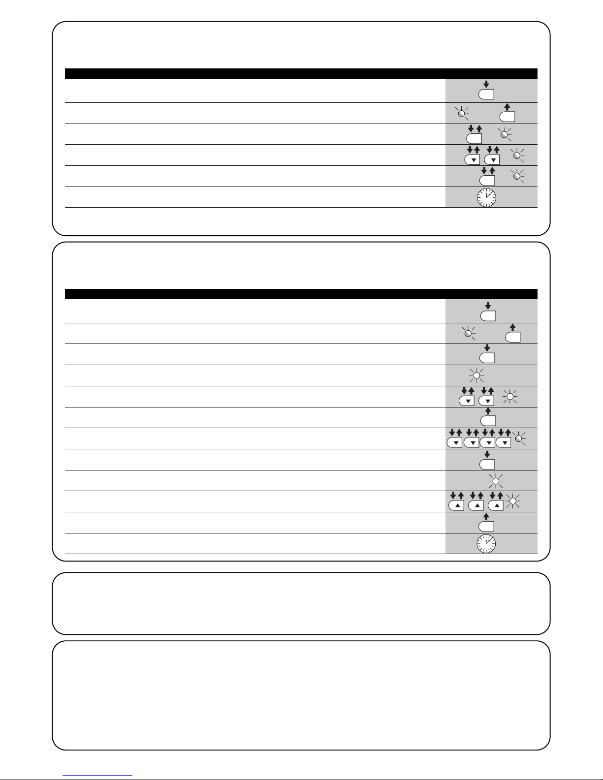
94
7.2.6 Zweites Niveau: Programmierungsbeispiel (einstellbare Parameter)
Als Beispiel wird die Sequenz der Vorgänge angegeben, die auszuführen sind, um die werkseitige Einstellung der Parameter zu ändern und die “Pausezeit”
auf 60 Sekunden zu erhöhen (Eingang an L1 und Niveau auf L2) und die “Motorkraft” für leuchte Tore zu verringern (Eingang an L5 und Niveau auf L2).
1. Auf Taste [Set] drücken und ca. 3 Sekunden gedrückt halten [Set]
3s
2. Taste [Set] loslassen, wenn LED L1 zu blinken beginnt
L1
3. Auf Taste [Set]; drücken und gedrückt halten; die Taste [Set] muss während der Schritte
4 und 5 ständig gedrückt bleiben
4. Ca. 3s warten, danach wird die LED L3 aufleuchten,
die das aktuelle Niveau der “Pausezeit” darstellt L3 3s
5. Zweimal auf Taste [▼] drücken, damit das Blinken auf LED L5 übergeht,
die den neuen Wert der “Pausezeit” darstellt L5
6. Die Taste [Set] loslassen
7. Viermal auf Taste [▼] drücken, damit das Blinken auf LED L5 übergeht
L5
8. Auf Taste [Set]; drücken und gedrückt halten; die Taste [Set] muss während der Schritte
9 und 10 ständig gedrückt bleiben
9. Ca. 3s warten, danach wird die LED L5 aufleuchten,
die das aktuelle Niveau der “Motorkraft” darstellt 3s L5
10. Dreimal auf Taste [▲] drücken, damit das Blinken auf LED L2 übergeht,
die den neuen Wert der “Motorkraft” darstellt L2
11. Die Taste [Set] loslassen
12. 10s warten, um die Programmierung aufgrund des Ablaufs der Zeitgrenze zu beenden.
10s
Tabelle 12: Zweites Niveau - Programmierungsbeispiel Beispiel
SET
SET
SET
SET
SET
SET
7.3 Hinzufügen oder Entfernen von Vorrichtungen
Einer Automatisierung mit ROBUS können jederzeit Vorrichtungen hinzugefügt bzw. aus dieser entfernt werden. Insbesondere können an
“BlueBUS” und am Eingang “STOP” verschiedenartige Vorrichtungen
angeschlossen werden, wie in den folgenden Paragraphen angegeben.
Nachdem Vorrichtungen hinzugefügt oder entfernt worden
sind, muss die Erlernung der Vorrichtungen wie in Par.
“7.3.6 Erlernung sonstiger Vorrichtungen” beschrieben
wiederholt werden.
7.3.1) BlueBUS
BlueBUS ist eine Technik, mit der kompatible Vorrichtungen mit nur
zwei Leitern, auf denen sowohl die Stromversorgung als auch die Kommunikationssignale übermittelt werden, angeschlossen werden können. Alle Vorrichtungen werden an den 2 BlueBUS Leitern parallel
geschaltet; eine Polung ist nicht zu beachten. Jede Vorrichtung wird
einzeln erkannt, da ihr während der Installation eine eindeutige Adresse
zugeteilt wird. An BlueBUS kann man zum Beispiel Photozellen, Sicherheitsvorrichtungen, Steuertasten, Leuchtmelder usw. anschließen.
Die Steuerung von ROBUS erkennt nacheinander alle angeschlossenen Vorrichtung durch eine geeignete Erlernung und ist imstande,
alle möglichen Störungen mit höchster Sicherheit wahrzunehmen.
Deshalb muss an der Steuerung jedes Mal, wenn eine an BlueBUS
angeschlossene Vorrichtung hinzugefügt oder entfernt wird, die
Erlernphase ausgeführt werden, wie in Par. “7.3.6 Erlernung sonstiger Vorrichtungen” beschrieben.
7.2.5 Erstes Niveau - Programmierungsbeispiel (ON-OFF-Funktionen)
Als Beispiel wird die Sequenz der Vorgänge angegeben, die auszuführen sind, um die werkseitige Einstellung zur Aktivierung der Funktionen
“Automatische Schließung” (L1) und “Schließt immer” (L3) zu ändern.
1. Auf Taste [Set] drücken und ca. 3 Sekunden gedrückt halten
3s
2. Taste [Set] loslassen, wenn LED L1 zu blinken beginnt
L1
3. Einmal auf Taste [Set] drücken, um den Status der L1 zugeordneten Funktion
(Automatische Schließung) zu ändern; L1 führt nun ein langes Blinken aus L1
4. Zweimal auf Taste [▼] drücken, damit das Blinken auf LED L3 übergeht
L3
5. Einmal auf Taste [Set] drücken, um den Status der L3 zugeordneten Funktion
(Schließt immer) zu ändern; L3 führt nun ein langes Blinken aus L3
6. 10s warten, um die Programmierung aufgrund des Ablaufs der Zeitgrenze zu beenden.
10s
Am Ende dieser Vorgänge müssen die LEDS L1 und L3 eingeschaltet bleiben, was bedeutet, dass die Funktionen “Automatische
Schließung” und “Schließt immer” aktiviert sind.
Tabelle 11: Erstes Niveau - Programmierungsbeispiel Beispiel
SET
SET
SET
SET

95
D
7.3.2 Eingang STOP
STOP ist der Eingang, der das unverzügliche Anhalten der Bewegung
verursacht, gefolgt von einer kurzen Umkehrung. An diesen Eingang
können Vorrichtungen mit Ausgang mit gewöhnlich geöffnetem “NO”Kontakt, mit gewöhnlich geschlossenem “NC”-Kontakt oder Vorrichtungen mit Ausgang mit konstantem 8,2KΩ Widerstand, wie zum Beispiel Schaltleisten, angeschlossen werden.
Wie für BlueBUS, erkennt die Steuerung die am Eingang STOP angeschlossene Vorrichtung während der Erlernung – siehe Paragraph
“7.3.6 Erlernung sonstiger Vorrichtungen”; danach wird ein STOP verursacht, wenn eine beliebige Variation des erlernten Status erfolgt.
Mit entsprechenden Maßnahmen kann am Eingang STOP mehr als
eine Vorrichtung auch anderen Typs angeschlossen werden.
• Mehrere NO-Vorrichtungen können miteinander in unbegrenzter
Menge parallelgeschaltet werden.
• Mehrere NC-Vorrichtungen können miteinander in unbegrenzter
Menge seriengeschaltet werden.
• Zwei Vorrichtungen mit konstantem 8,2KΩ Widerstand können
parallelgeschaltet werden, im Falle von mehr als 2 Vorrichtungen
müssen alle mit nur einem 8,2KΩ Endwiderstand “kaskadengeschaltet” werden
• Die Kombination NO und NC ist möglich, wenn die 2 Kontakte
parallelgeschaltet werden, wobei ein 8,2KΩ Widerstand mit dem
NC-Kontakt seriengeschaltet werden muss (daher ist auch die
Kombination von 3 Vorrichtungen NO, NC und 8,2KΩ möglich).
Falls der Eingang STOP für den Anschluss von Vorrichtungen mit Sicherheitsfunktionen benutzt wird, garantieren nur die Vorrichtungen mit Ausgang mit konstantem
8,2KΩ Widerstand die Sicherheitsklasse 3 gegen Defekte
gemäß der Vorschrift EN 954-1.
!
FOTO
Photozelle außen h = 50
mit Auslösung in Schließung;
FOTO II
Photozelle außen h = 100
mit Auslösung in Schließung
FOTO 1
Photozelle innen h = 50
mit Auslösung in Schließung;
FOTO 1 II
Photozelle innen h = 100
mit Auslösung in Schließung;
FOTO 2
Photozelle außen
mit Auslösung in Öffnung
FOTO 2 II
Photozelle innen
mit Auslösung in Öffnung
FOTO 3
nur eine Photozelle für den
ganzen Automatismus
Wenn FOTO 3 zusammen mit FOTO II installiert wird, muss die
Position der Photozellenelemente (TX - RX) gemäß den Angaben in
den Anweisungen der Photozellen sein.
!
7.3.3 Photozellen
Das System “BlueBUS” ermöglicht durch die Adressierung mit speziellen Überbrückungen die Erkennung der Photozellen seitens der
Steuerung und die Zuteilung der korrekten Wahrnehmungsfunktion.
Die Adressierung muss sowohl an TX als auch an RX ausgeführt
werden (wobei die Überbrückungen auf dieselbe Art anzuordnen
sind). Überprüft werden muss, dass andere Photozellenpaare nicht
dieselbe Adresse haben.
An einem Schiebetorautomatismus mit ROBUS können die Photozellen wie auf Abbildung 24 gezeigt installiert werden.
Nach der Installation oder Entfernung von Photozellen muss an der
Steuerung die Erlernphase ausgeführt werden, wie in Par. “7.3.6
Erlernung sonstiger Vorrichtungen” beschrieben.
7.3.4) Lichtsensor FT210B
Der Lichtsensor FT210B vereint in einer einzigen Vorrichtung das
Kraftbegrenzungssystem (Typ C gemäß EN12453) und einen Präsenzdetektor, der Hindernisse auf der optischen Achse zwischen
Sender TX und Empfänger RX wahrnimmt (Typ D gemäß EN12453).
Die Statussignale der Schaltleiste werden über den Strahl der Photozelle in den Lichtsensor FT210B gesendet, wodurch 2 Systeme in
einer einzigen Vorrichtung integriert sind. Der übertragende Teil am
beweglichen Torflügel ist durch Batterien gespeist, was unschöne
Anschlüsse verhindert; spezielle Kreisläufe verringern den Verbrauch
der Batterie, deren Dauer bis zu 15 Jahre lang garantiert wird (siehe
Details dieser Schätzung in den Anweisungen des Produkts).
Mit nur einer Vorrichtung FT201B, kombiniert mit einer Schaltleiste
(z.B. TCB65) kann das Sicherheitsniveau der “Hauptschaltleiste”
erreicht werden, das von Norm EN12453 für jede Art von “Benutzung” und “Aktivierung” verlangt ist. Der Lichtsensor FT210B in
Kombination mit resistiven Schaltleisten (8,2Kohm) funktioniert auch,
wenn ein Teil defekt ist (Klasse 3 gemäß EN 954-1). Er verfügt über
einen speziellen Antikollisionskreislauf, der Interferenzen mit anderen,
auch nicht synchronisierten Detektoren verhindert und die Hinzufügung weiterer Photozellen ermöglicht, wie zum Beispiel für die
Durchfahrt von schweren Fahrzeugen, wo gewöhnlich eine zweite
Photozelle in 1 m Höhe ab Boden angebracht wird.
Für weitere Auskünfte über Anschluss und Adressierung wird auf die
Anleitung von FT210B verwiesen.
24
Tabelle 14: Adressierungen der Photozellen
Photozelle Überbrückungen Photozelle Überbrückungen

96
7.3.5) ROBUS in Modalität “Slave”
Durch geeignete Programmierung und Anschluss kann ROBUS als
“Slave” funktionieren; diese Funktionsweise wird angewendet, wenn
2 gegenüber liegende Torflügel automatisiert werden sollen und man
will, dass die Bewegungen der Torflügel synchronisiert erfolgen. In
dieser Modalität funktioniert ein ROBUS als Master bzw. er steuert
die Bewegungen, wogegen der andere ROBUS als Slave funktioniert
bzw. die vom Master gesendeten Befehle ausführt (werkseitig sind
alle ROBUS Master).
Um ROBUS als Slave zu konfigurieren, muss die Funktion “Slave
Modus” auf erstem Niveau aktiviert werden (siehe Tabelle 7).
Die Verbindung zwischen Master und Slave ROBUS erfolgt über BlueBUS.
In diesem Fall muss die Polung des Anschlusses zwischen den beiden ROBUS beachtet werden, wie in Abbildung 26 gezeigt (die anderen Vorrichtungen werden weiterhin keine Polung haben).
Für die Installation von 2 ROBUS als Master und Slave ist wie folgt
vorzugehen:
• Die beiden Motoren wie in Abbildung 25 gezeigt installieren. Wel-
cher Motor als Master und als Slave funktioniert, ist nicht von
Bedeutung; bei der Wahl auf die Bequemlichkeit der Anschlüsse
achten und auf die Tatsache, dass der Befehl Schrittbetrieb am Slave nur die vollständige Öffnung des Torflügels Slave bewirken wird.
• Die beiden Motoren wie in Abbildung 26 gezeigt anschließen.
• Die Richtung der Öffnungsbewegung der 2 Motoren auswählen,
wie in Abbildung 25 angegeben (siehe auch Par. “4.1 Auswahl der
Richtung”).
• Die beiden Motoren speisen.
• Am Slave ROBUS, die Funktion “Slave Modus” programmieren
(siehe Tabelle 7).
• Die Erfassung der Vorrichtungen am Slave ROBUS ausführen (siehe Par. “4.3 Erlernung der Vorrichtungen”).
• Die Erfassung der Vorrichtungen am Master ROBUS ausführen
(siehe Par. “4.3 Erlernung der Vorrichtungen”).
• Die Erfassung der Länge der Torflügel am Master ROBUS ausführen (siehe Par. “4.4 Erlernung der Torflügellänge”).
!
25
26
Beim Anschluss von 2 ROBUS im Modus Master-Slave ist folgendes zu beachten:
• Alle Vorrichtungen inklusive Funkempfänger müssen am Master ROBUS angeschlossen sein (wie in Abb. 26)
• Falls Pufferbatterien benutzt werden, müssen beide Motoren über eine eigene Batterie verfügen.
• Alle Programmierungen am Slave ROBUS mit Ausnahme jener in Tabelle 14 werden ignoriert (die Programmierungen am Master ROBUS
herrschen vor).
LUCYB
S.C.A.
MOFB
MOSE
OPEN
CLOSE
LUCYB
S.C.A.
STOP
PP

97
D
7.4.1) Funktion “Öffnet Immer”
Die Funktion “Öffnet Immer” ist eine Besonderheit der Steuerung, mit der
immer eine Öffnungsbewegung erfolgt, wenn der Befehl “Schrittbetrieb”
länger als 2 Sekunden gegeben wird; das ist zum Beispiel nützlich, um an
Klemme Schrittbetrieb den Kontakt einer Zeituhr anzuschließen,
damit das Tor in einer bestimmten Zeitspanne geöffnet bleibt. Diese Eigenschaft ist unabhängig von der Programmierung des Eingangs P.P. (Schrittbetrieb), außer wenn dieser Eingang als “Schließt” programmiert ist – siehe
Parameter “Funktion Schrittbetrieb” in Tabelle 9.
7.4.2) Funktion “Todmann”
Wenn eine Sicherheitsvorrichtung nicht korrekt funktionieren oder
außer Betrieb sein sollte, kann das Tor in der Modalität “Todmann”
bewegt werden. Für Einzelheiten wird auf den Paragraph “Torbewe
gung mit Sicherheitsvorrichtungen außer Betrieb” in der Anlage
“Anweisungen und Hinweise für den Benutzer des Toröffners
ROBUS” verwiesen.
7.4.3) Wartungsanzeige
ROBUS warnt den Benutzer, wann eine Wartung der Automatisierung
ausgeführt werden soll. Die Anzahl an Bewegungen, nach der die Anzeige
erfolgt, kann im einstellbaren Parameter “Wartungsanzeige” (siehe Tabelle 9)
auf 8 Niveaus ausgewählt werden.
Das Niveau 1 ist “automatisch” und berücksichtigt die Beschwerlichkeit der
Bewegungen bzw. den Kraftaufwand und die Dauer der Bewegung, wogegen die anderen Niveaus von der Anzahl der Bewegungen ausgehen.
Die Wartungsanzeige erfolgt an der Blinkleuchte Flash oder der am
Ausgang S.C.A. angeschlossenen Kontrolllampe, falls als “Wartungskontrolllampe” programmiert (siehe Tabelle 9).
Je nach Anzahl an ausgeführten Bewegungen im Vergleich zum programmierten Grenzwert geben die Blinkleuchte Flash und die Wartungskontrolllampe die in Tabelle 16 angegebenen Anzeigen ab.
7.4) Sonderfunktionen
Tabelle 14: vom Master ROBUS unabhängige Programmierungen am Slave ROBUS
Funktionen des ersten Niveaus (ON-OFF-Funktionen)
Funktionen des zweiten Niveaus (einstellbare Parameter)
Stand-by Motorgeschwindigkeit
Anlauf SCA-Ausgang
Modus “Slave” Motorkraft
Alarmliste
Am Slave kann folgendes angeschlossen werden:
•
eine eigene Blinkleuchte (Flash)
• eine eigene Kontrolllampe Tor geöffnet (S.C.A.)
•
eine eigene Schaltleiste (Stop)
•
eine eigene Steuervorrichtung (P.P. = Schrittbetrieb) für die vollständige Öffnung nur des Torflügels Slave.
•
Am Slave sind die Eingänge Open und Close nicht benutzt.
7.3.6 Erlernung sonstiger Vorrichtungen
Gewöhnlich erfolgt die Erlernung der an BlueBUS und am Eingang STOP angeschlossenen Vorrichtungen bei der Installation; wenn jedoch Vorrichtungen hinzugefügt bzw. entfernt werden, kann die Erlernung wie in Tabelle 15 angegeben erneut ausgeführt werden.
1. Auf die Tasten [▲] und [Set] drücken und gedrückt halten
2. Die Tasten loslassen, wenn die LEDs L1 und L2 sehr schnell zu blinken beginnen (nach ca. 3 Sekunden)
L1 L2
3.
Ein paar Sekunden warten, bis die Steuerung die Erlernung der Vorrichtungen beendet.
4.
Am Ende der Erlernung werden sich die LEDs L1 und L2 ausschalten, die LED STOP muss weiterhin leuchten,
wogegen die
LEDs L1…L8 je nach dem Status der ON-OFF Funktionen, die sie darstellen, aufleuchten werden. L1 L2
Nachdem Vorrichtungen hinzugefügt oder entfernt worden sind, muss die Abnahme der Automatisierung erneut
ausgeführt werden, wie in Par. “5.1 Abnahme” beschrieben.
!
Tabelle 15: Erlernung sonstiger Vorrichtungen Beispiel
SET
SET
Anzahl an Bewegungen Anzeige an Flash Anzeige an Wartungskontrolllampe
Unter 80% des Grenzwertes
Zwischen 81 und 100% des Grenzwertes
Über 100% des Grenzwertes
Normal (0,5 Sek. ein, 0,5 Sek. aus)
Bleibt bei Öffnungsbeginn 2 Sek. eingeschaltet, blinkt dann normal weiter
Bleibt bei Bewegungsbeginn und am Ende der Bewegung 2 Sek. eingeschaltet, blinkt dann normal weiter
Ein für 2 Sek. bei Öffnungsbeginn
Blinkt während der ganzen Bewegung.
Blinkt immer
Tabelle 16: Wartungsanzeige mit Flash und Wartungskontrolllampe

98
1. Premere e tener premuto il tasto [Set] per circa 3s
3s
2. Auf Taste [Set] drücken und ca. 3 Sekunden gedrückt halten
L1
3. Auf die Tasten [▲] oder [▼] drücken, um das Blinken auf die LED L7,
die “Eingangs-LED” des Parameters “Wartungsanzeige” zu verschieben oder L7
4. Auf Taste [Set], drücken und gedrückt halten; die Taste [Set] muss während
der Schritte 5, 6 und 7 ständig gedrückt bleiben
5. Ca. 3s warten, danach wird die LED aufleuchten,
die das aktuelle Niveau des Parameters “Wartungsanzeige“ darstellt 3s
6. Auf die Tasten [▲] und [▼] drücken und sofort loslassen.
und
7.
Die LED, die dem gewählten Niveau entspricht, wird mehrmals blinken. Die Anzahl an Blinkvorgängen steht für den Prozentsatz an
ausgeführten Bewegungen (Vielfaches von 10%) im Vergleich zum eingestellten Grenzwert. Beispiel: eingestellt ist die
Wartungsanzeige an L6 mit 10000. 10% entspricht 1000 Bewegungen. Wenn die LED vier Mal blinkt, ist 40% der Bewegungen
erreicht worden (zwischen 4000 und 4999 Bewegungen). Unter 10% der Bewegungen erfolgt kein Blinken.
8. Die Taste [Set] loslassen.
Überprüfung der Anzahl an ausgeführten Bewegungen
Mit der Funktion “Wartungsanzeige” kann die Anzahl an ausgeführten Bewegungen als Prozentsatz des eingestellten Grenzwertes überprüft
werden. Die Überprüfung wie in Tabelle 17 beschrieben ausführen.
Tabelle 17: Überprüfung der Anzahl an ausgeführten Bewegungen Beispiel
SET
SET
SET
SET
.... n=?
Nullstellung des Bewegungszählers
Nach der Wartung der Anlage muss der Bewegungszähler auf Null gestellt werden.
Wie in Tabelle 18 beschrieben vorgehen.
1. Auf Taste [Set] drücken und ca. 3 Sekunden gedrückt halten
3s
2. Taste [Set] loslassen, wenn LED L1 zu blinken beginnt
L1
3. Auf die Tasten [▲] oder [▼] drücken, um das Blinken auf die LED L7,
die “Eingangs-LED” des Parameters “Wartungsanzeige” zu verschieben oder L7
4. Auf Taste [Set], drücken und gedrückt halten; die Taste [Set] muss während der Schritte
5 und 6 ständig gedrückt bleiben
5. Ca. 3s warten, danach wird die LED aufleuchten, die das aktuelle
Niveau des Parameters “Wartungsanzeige” darstellt 3s
6. Mindestens 5 Sekunden lang auf die Tasten [▲] und [▼], drücken und gedrückt halten, dann die
beiden Tasten loslassen. Die LED, die dem gewählten Niveau entspricht, wird mehrmals schnell blinken
und so anzeigen, dass der Bewegungszähler auf Null gestellt worden ist. und
7. Die Taste [Set] loslassen.
Tabelle 18: Nullstellung des Bewegungszählers Beispiel
SET
SET
SET
SET
7.5 Verbindung sonstiger Vorrichtungen
Sollte es notwendig sein, externe Vorrichtungen wie zum Beispiel
einen Proximity-Leser für Transponder-Cards oder die Beleuchtung
des Schlüsseltasters anzuschließen, kann die Versorgung wie in
Abbildung 27 gezeigt entnommen werden. Die Versorgungsspannung ist 24Vcc -30% ÷ +50% mit zur Verfügung stehendem Höchststrom von 100mA.
-+
24Vcc
27

99
D
7.7) Diagnose und Anzeigen
Einige Vorrichtungen bieten selbst besondere Anzeigen, mit denen der
Betriebsstatus oder eventuelle Störungen erkannt werden können.
7.6) Probleme und deren Lösungen
In Tabelle 19 sind nützliche Hinweise zu finden, um eventuelle
Betriebsstörungen zu beheben, die bei der Installation oder im Falle
von Defekten auftreten können.
29
Tabelle 19: Fehlersuche
Symptome Empfohlene Überprüfungen
Der Funksender schaltet das Tor nicht und die
LED am Sender leuchtet nicht auf.
Der Funksender schaltet das Tor nicht, aber die
LED am Sender leuchtet auf.
Es erfolgt keine Bewegung und die
BlueBUS-LED blinkt nicht.
Es erfolgt keine Bewegung und die Blinkleuchte
blinkt nicht.
Es erfolgt keine Bewegung und die Blinkleuchte
blinkt mehrmals.
Die Bewegung beginnt, aber gleich danach
erfolgt eine Umkehrung.
Die Bewegung wird ordnungsgemäß ausgeführt,
aber die Blinkleuchte funktioniert nicht.
Die Bewegung wird ordnungsgemäß ausgeführt,
aber die Kontrolllampe SCA funktioniert nicht.
Prüfen, ob die Batterien des Senders leer sind, ggf. auswechseln.
Prüfen, ob der Sender korrekt im Funkempfänger gespeichert ist.
Prüfen, ob ROBUS mit der Netzspannung gespeist ist.
Prüfen, ob die Sicherungen unterbrochen sind; in diesem Fall die Ursache des Defekts überprüfen,
dann die Sicherungen mit anderen mit demselben Stromwert und denselben Merkmalen auswechseln.
Prüfen, ob der Befehl effektiv empfangen wird. Falls der Befehl am Eingang PP angelangt, muss die jeweilige LED “PP” aufleuchten, wenn dagegen der Funksender
benutzt wird, muss die BlueBUS-LED zweimal schnell blinken.
Zählen, wie oft die Blinkleuchte blinkt und nach den Angaben in Tabelle 21 überprüfen.
Die gewählte Kraft könnte für das Tor zu gering sein. Prüfen, ob Hindernisse vorhanden sind und ggf. eine stärkere Kraft wählen.
Prüfen, dass während der Bewegung Spannung an der Klemme FLASH der Blinkleuchte
anliegt (da intermittierend, ist der Spannungswert ca. 10-30Vcc nicht von Bedeutung); wenn
Spannung vorhanden ist, liegt das Problem an der Glühbirne, die mit einer anderen mit denselben Merkmalen ersetzt werden muss; wenn keine Spannung vorhanden ist, könnte eine
Überlastung am Ausgang FLASH erfolgt sein; prüfen, ob das Kabel kurzgeschlossen ist.
Prüfen, welche Funktion für den Ausgang SCA programmiert ist (Tabelle 9).
Wenn die Kontrolllampe eingeschaltet sein sollte, prüfen, ob ca. 24Vcc Spannung an der Klemme
SCA anliegen; wenn Spannung vorhanden ist, liegt das Problem an der Glühbirne, die mit einer
anderen mit denselben Merkmalen ersetzt werden muss; wenn keine Spannung vorhanden ist,
könnte eine Überlastung am Ausgang SCA erfolgt sein; prüfen, ob das Kabel kurzgeschlossen ist.
F2
F1
1. Auf Taste [Set] drücken und ca. 3 Sekunden gedrückt halten
3s
2. Taste [Set] loslassen, wenn LED L1 zu blinken beginnt ∑
L1
3. Auf die Tasten [▲] oder [▼] drücken, um das Blinken auf die LED L8,
die “Eingangs-LED” des Parameters “Alarmhistorik” zu verschieben oder L8
4. Auf Taste [Set], drücken und gedrückt halten; die Taste [Set]
muss während der Schritte 5 und 6 ständig gedrückt bleiben
5. Ca. 3s warten, danach werden die LEDs aufleuchten, die den Bewegungen mit der Störung entsprechen.
L1 gibt das Ergebnis der letzten Bewegung an, L8 das Ergebnis der achten. Wenn die LED leuchtet, haben sich
Störungen während der Bewegung ereignet, wenn sie ausgeschaltet ist, wurde die Bewegung störungsfrei beendet.
6. Auf die Tasten [▲] und [▼] drücken, um die gewünschte Bewegung auszuwählen:
Die entsprechende LED wird sooft blinken, wie die Blinkleuchte gewöhnlich
nach einer Störung blinkt (siehe Tabelle 21).
und
7. Die Taste [Set] loslassen.
Tabelle 20: Liste der Alarmhistorik Beispiel
SET
SET
SET
SET
7.6.1) Liste der Alarmhistorik
ROBUS ermöglicht es, eventuelle Störungen bei den 8 letzten Bewegungen zu sehen, wie z.B. die Unterbrechung einer Bewegung infolge
der Auslösung einer Photozelle oder Schaltleiste.
3s

100
BlueBUS-LED Ursache HANDLUNG
LED STOP Ursache HANDLUNG
LED STOP Ursache HANDLUNG
LED STOP Ursache HANDLUNG
Aus
7.7.2) Anzeigen durch die Steuerung
An der Steuerung von ROBUS befinden sich verschiedene LEDs,
von denen jede sowohl im Normalbetrieb als auch bei Störungen
besondere Anzeigen geben kann.
Tabelle 22: LEDs an den Klemmen der Steuerung
Störung
Prüfen, ob die Stromversorgung vorhanden ist; prüfen, ob die Sicherungen ausgelöst wurden; ggf. die
Ursache des Defekts überprüfen, dann die Sicherungen mit anderen mit demselben Wert auswechseln.
Ein Schwere Störung
Eine schwere Störung liegt vor, versuchen, die Steuerung ein paar Sekunden abzuschalten; falls dieser
Status bleibt, ist ein Defekt vorhanden und die elektronische Steuerkarte muss ausgewechselt werden.
1-Mal Blinken pro Sekunde
Alles OK Normalbetrieb der Steuerung
2-Mal Schnellblinken
Es erfolgte eine Statusvariation der Eingänge
Ist normal, wenn eine Änderung eines der Eingänge PP, STOP, OPEN, CLOSE erfolgt
oder die Photozellen ansprechen oder der Funksender benutzt wird.
Mehrmaliges Blinken mit
1 Sekunde Pause
Verschiedenes Ist dieselbe Anzeige, die an der Blinkleuchte erfolgt – siehe Tabelle 21.
Aus
Auslösung des Eingangs
STOP
Die am Eingang STOP angeschlossenen Vorrichtungen überprüfen
Acceso Alles OK Eingang STOP aktiv
Aus Alles OK Eingang PP nicht aktiviert
Ein
Aus
Auslösung des Eingangs PP
Alles OK
Ist normal, wenn die am Eingang PP angeschlossene Vorrichtung effektiv aktiviert ist
Eingang ÖFFNET nicht aktiviert
Ein
Auslösung des Eingangs OPEN
Ist normal, wenn die am Eingang ÖFFNET angeschlossene Vorrichtung effektiv aktiviert ist
LED STOP Ursache HANDLUNG
Aus Alles OK Eingang SCHLIEßT nicht aktiviert
Ein
Auslösung des Eingangs CLOSE
Ist normal, wenn die am Eingang SCHLIEßT angeschlossene Vorrichtung effektiv aktiviert ist
29
6-Mal Blinken
1 Sekunde Pause
6-Mal Blinken
Nach der Überprüfung bei Bewegungsbeginn entsprechen die an BlueBUS angeschlossenen Vorrichtungen nicht den während der Erlernung gespeicherten. Es
können defekte Vorrichtungen vorhanden sein: überprüfen und ersetzen. Falls
Änderungen ausgeführt worden sind, muss die Erlernung wiederholt werden
7.7.1) Anzeigen durch die Blinkleuchte
Die Blinkleuchte FLASH blinkt während der Bewegung einmal pro Sekunde; im Falle von Störungen wird das Blinken schneller sein; die Blinkvorgänge wiederholen sich zweimal mit einer Pause von einer Sekunde.
Tabelle 21: Anzeigen durch die Blinkleuchte FLASH
Schnellblinken Ursache HANDLUNG
1-Mal Blinken
1 Sekunde Pause
1-Mal Blinken
Fehler an BlueBUS
2-Mal Blinken
1 Sekunde Pause
2-Mal Blinken
Auslösung einer Photozelle
Bei Bewegungsbeginn wird die Zustimmung zur Bewegung von einer oder mehreren Photozellen nicht gegeben; prüfen, ob Hindernisse vorhanden sind.
Während der Bewegung ist das normal, wenn effektiv ein Hindernis vorhanden ist.
3-Mal Blinken
1 Sekunde Pause
3-Mal Blinken
Auslösung des “Motorkraft”
Begrenzers Während der Bewegung war mehr Reibung am Tor vorhanden;
Ursache überprüfen.
4-Mal Blinken
1 Sekunde Pause
4-Mal Blinken
Auslösung des Eingangs
STOP
Am Anfang oder während der Bewegung erfolgte eine Auslösung des Eingangs
STOP; Ursache überprüfen
5-Mal Blinken
1 Sekunde Pause
5-Mal Blinken
Fehler in den internen Parametern der elektronischen
Steuerung
Mindestens 30 Sekunden warten und den Befehl erneut erteilen; sollte dieser
Status bleiben, könnte ein schwerer Defekt vorhanden sein, und die elektronische Steuerkarte muss ausgewechselt werden.
Die Höchstgrenze an Bewegungen pro Stunde wurde
überschritten
Ein paar Minuten warten, bis der Bewegungsbegrenzer wieder unter die Höchstgrenze zurückkehrt.
7-Mal Blinken
1 Sekunde Pause
7-Mal Blinken
8-Mal Blinken
1 Sekunde Pause
8-Mal Blinken
Fehler in den internen
elektrischen
Es wurde bereits ein Befehl
erteilt, so dass andere Befehle
nicht ausgeführt werden können.
Alle Versorgungskreise ein paar Sekunden abschalten, dann den Befehl erneut
erteilen; sollte dieser Status bleiben, könnte ein schwerer Defekt vorhanden
sein, und die elektronische Steuerkarte muss ausgewechselt werden.
Die Art des vorhandenen Befehls überprüfen. Es könnte sich zum Beispiel um
einen Befehl durch eine Uhr am Eingang “Öffne” handeln.
 Loading...