


control unit
robo, thor, otto
Instructions and warnings for the fitter
Istruzioni ed avvertenze per l’installatore
Instructions et recommandations pour l’installateur
Anweisungen und Hinweise für den Installateur
Instrucciones y advertencias para el instalador
Instrukcje i uwagi dla instalatora
Aanwijzingen en aanbevelingen voor de installateur

2
robo,th

NL
GB
I
F
D
E
PL

4
control unit
gearmotors
robo, thor, otto
Warnings:
This manual has been especially written for use by
qualified fitters. No information given in this manual can be
considered as being of interest to end users!
This manual only refers to this control unit and may not be
used for different products.
Do not install the unit before you have read all the instructions at least
once.
!
Table of contents: page
1 Description of the product 5
2 Installation 6
2.1 Typical system layout 6
2.2 Electrical connections 6
2.2.1 Electrical diagram 7
2.2.2 Description of connections 7
2.2.3 Phototest 8
2.2.4 Checking connections 9
3 Adjustments 9
4 Testing 10
5 Operating modes 11
page
6 Programmable functions 11
6.1 Description of functions 12
7 Using 2 control units on opposed leafs 13
8 Accessories 14
9 Maintenance 14
10 Disposal 14
11 What to do if... 15
12 Technical specifications 15

GB
5
1) Description of the product:
This gate and door automation unit controls the ROBO, OTTO and
THOR gearmotors with single-phase alternating current.
The control unit varies depending on the type of gearmotor to control,
e.g.: Force Adjustment, Gate Open Indicator and Courtesy Light.
It also features a series of functions that can be selected by “DipSwitches” (mini-switches) and adjustments performed by Trimmers.
The control unit features input status Led’s located near such inputs,
while another Led near the microprocessor indicates that the internal
logic works correctly.
To make it easier to recognise the various parts, fig.1 shows the
main components.
LMNOP
J
QRST
VU
I
X
W
Y
H
G
FZ
EDCBA
CH
P. P.
AP
FOTO
FCA
FCC
OK
Function selection Dip-Switch
Force adjustment trimmer
Working Time TL adjustment trimmer
Pause Time TP adjustment trimmer
Terminal board for aerial and 2nd channel
RADIO board slot
Input status LED’s
Input/output control terminal board
“Common” relay
Power input terminal board / Flashing light
Primary transformer connector
Line fuse (5A)
“Courtesy Light” output connector (only on OTTO)
Motor power output
Capacitor slot connector
“Torque” relay
Triac “Courtesy Light” (only on OTTO)
Triac Close
Triac Open
Secondary transformer connector
FCA / FCC limit switch input
Low voltage rapid fuse (500mA)
PIU board slot
OK Led
Microprocessor
A
B
C
D
E
F
G
H
I
J
L
M
N
O
P
Q
R
S
T
U
V
W
X
Y
Z
1
Product Code* Control Unit Code* Additional Function
ROBO
RO1000
RO1020
ROA3 Force adjustment Trimmer
RO1010 ROA4 “Torque” Relay
THOR
TH1551 THA5 Force adjustment Trimmer
TH2251 THA6 “Torque” Relay
OTTO OT21 OTA1 “Courtesy Light” output
* = add to code V1 for the 120 V 50/60 Hz version.

6
2.1) Typical system layout
In order to explain certain terms and aspects of an automatic door or gate system, we will now illustrate a typical system layout.
ROBO / THOR OTTO
1) Pair of ““Photo” photocells
2) Flashing lamp
3) Keylock selector
4) Pneumatic edge
5) Pair of “Photo 2” photocells
In particular, please note that:
• All the photocells produced by NICE feature the synchronism system which eliminates the problem of interference between
two pairs of photocells (please consult the photocell instructions for further details).
• The ““Photo” pair of photocells have no effect during opening while they invert movement during closing.
• The ““Photo2” pair of photocells have no effect during closing while they invert movement during opening.
Automatic gate and door systems may only be installed by
qualified fitters in the full respect of the law. Comply with the
warnings shown in the “Warnings for fitters” file.
!
2) Installation:
2a
2b
PHOTO
PHOTO
PHOTO 2
5
3
2
1
3
4
PHOT
O
2
1
2.2) Electrical connections
To safeguard the operator and avoid damaging the
components while you are wiring or plugging in the
various cards: under no circumstances may the unit be
electrically powered.
• Power the unit using a 3 x 1.5 mm
2
cable: should the distance
between the unit and the earth connection exceed 30m, install
an earth plate near the unit.
• Use wires with a minimum cross-section of 0.25mm
2
to connect
low voltage safety circuits.
• Use shielded wires if the length exceeds 30m and only connect
the earth braid to the control unit side.
• Do not make connections to cables in buried boxes even if they
are completely watertight.
• If the inputs of the Normally Closed (NC) contacts are not used
they should be jumped with the “24V common” terminal except
for the photocell inputs if the phototest function is enabled, for
further information please see the “Phototest” paragraph.
• If there is more than one (NC) contact on the same input, they
must be connected in SERIES.
• If the inputs of the Normally Open (NA) contacts are not used
they should be left free.
• If there is more than one (NA) contact on the same input, they
must be connected in Parallel.
• The contacts must be mechanical and potential-free; no stage
connections are allowed, such as those defined as "PNP",
"NPN", "Open Collector", etc..
!

GB
7
2.2.1) Electrical diagram
2.2.2) Description of connections
A brief description of the possible control unit output connections follows.
Terminals Functions Description
1-2 : Power input = Mains power line
3-4 : Flashing light = Output for connecting flashing light to mains voltage (max. 40W)
5-6 : 24 Vac = 24Vac output to 24Vac services (Photo, Radio, etc.) Max. 200mA
7 : Common = Common for all inputs
8:
Gate open indicator
= Max. 24 Vac output for gate open indicator 2W (Not used on OTTO)
9 : Stop = Input for stopping the manoeuvre with a brief reverse phase
10 : Photo = Input for safety devices (photocells, pneumatic edges)
11 : Step-by-step (PP) = Input for cyclic functioning (“Open” - “Stop” - “Close” - “Stop”)
12 : Open = Input for opening
13 : Close = Input for closing
41-42 : 2nd Radio Ch = Output for the second radio receiver channel if there is one
43-44 : Aerial = Input for the radio receiver aerial
3

8
2.2.3) Phototest
“Phototest” is the best possible solution for safety devices in terms
of reliability and it puts the control unit and safety photocells in
“category 2” according to UNI EN 954-1 standard (ed. 12/1998).
Before every manoeuvre is begun, the relative safety devices are
checked and only if everything is in order will the manoeuvre start.
Should the test be unsuccessful (the photocell is blinded by the sun,
cables have short circuited, etc.) the failure is identified and the
manoeuvre is not carried out.
To obtain the Phototest function:
• Using the additional “PIU” board.
• Setting Dip Switch 10 to ON
• Creating a special layout in the safety device connections as
shown in fig. 4a so that the photocell transmitters are no longer
directly powered by the service output but from terminals 7 and
8 of the “PIU” board. The maximum current that the “PIU” board
can use on the “Phototest” output is 100mA (2 pairs of nice
photocells)
• Powering the receivers directly from the service output of the
control unit (terminals 5-6).
If at a later time the Phototest function is no longer required, lower Dip
Switch 10 and modify the connection layout as shown in fig. 4b.
The photocells are tested as follows: when movement is required, it
is first checked that all the receivers involved in the movement give
their consent, then power to the transmitters is disconnected after
which it is checked that all the receivers signal the fact by removing
their consent; the transmitters are then powered and the consent of
all the receivers is verified once more. Only if this sequence is
successfully carried out will the manoeuvre be performed.
Synchronism should always be activated on the two transmitters by
cutting the jumpers; this is the only way of ensuring that the two
pairs of photoelectric cells do not interfere with one another.
Check the instructions in the photocell manual regarding
synchronised operation.
If a “Phototest” input is not used (e.g.: Photo2) but the “phototest”
function is required, jumper the unused input as shown in fig. 4c.
“Photo” and “Photo2” with “Phototest”
“Photo” and “Photo2” without “Phototest”
“Photo” with “Phototest”
4a
4b
4c

GB
9
2.2.4) Checking connections
The following operations entail working on live circuits; most of
these run on extra-low safety voltage so they are not dangerous but
some are contain mains voltage which means they are HIGHLY
DANGEROUS! Pay the greatest of attention to what you are doing
and NEVER WORK ALONE!
• Power the unit and check that voltage between terminals 5-6 is
approx. 24 Vac.
• Check that the “OK” Led flashes rapidly for a few moments and
then that it flashes at a regular frequency.
• Now check that the Led’s relative to the N.C. (Normally Closed)
contacts are on (all safety devices active) and that the Led’s
relative to the N.A. (Normally Open) inputs are off (no command
present); if this is not the case, check the connections of the
various devices and make sure they are in good working order.
The STOP input switches off both FCA and FCC.
• Make sure the limit switches are connected properly; move the
limit switch lever and check that the relative limit switch cuts in
and switches off the relative Led on the control unit.
• Release the leaf, take it to the halfway point and then block it; it
is now free to move in either the opening or closing direction.
• Now make sure that movement occurs in the right direction, that
is, see whether the movement set on the unit corresponds to
that of the leafs. This check is of paramount importance, if the
direction is wrong, in some cases (in the “Semiautomatic” mode,
for instance) the “Automatic” system might appear to be working
properly; in fact, the “Open” cycle is similar to the “Close” cycle
but with one basic difference: the safety devices are ignored in
the closing manoeuvre which is normally the most dangerous,
and they will trigger in the opening manoeuvre causing the gate
to close against the obstacle with disastrous results!
• To see whether or not the direction of rotation is correct, give a
short pulse to the Step-by-Step (PP) input; the first manoeuvre
the unit will carry out after being powered is always an “Open”
one, so simply verify that the automatic system moves in the
opening direction; if this movement is incorrect, proceed as
follows:
Turn the power off
Turn the motor and the limit switch power connectors
180°. (Ref. “O” and Ref. “V” of Fig.1)
Once this has been done, check whether the direction of
rotation is now correct by repeating previous point.
The “OK” Led located in the centre of the board has the task of
signalling the status of the internal logic: regular flashing at 1 second intervals
indicates that the internal microprocessor is active and waiting for commands.
When the microprocessor recognises a variation in the state of an input
(whether it is a command or a function Dip-Switch input) it generates a rapid
double flash even if the variation does not have any immediate effect.
Extremely rapid flashing for 3 s means that the control unit has just been
powered or is carrying out internal testing. Irregular flashing, lastly, means that
the test has been unsuccessful and that a fault has occurred.
!
Adjustments can be made with the trimmers that modify the
following parameters:
Working time (TL):
Adjusts the maximum duration of the opening or closing manoeuvre.
To adjust the working time TL, select the “Semiautomatic” operating
mode by moving Dip-Switch 1 to ON and adjust the TL trimmer to
halfway along the travel distance. Then run a complete opening
cycle followed by a complete closing cycle and readjust the TL
trimmer in order to leave enough time for the whole manoeuvre plus
a margin of about 2 to 3 s.
If the trimmer is at maximum and there still is not enough time, cut
the TLM jumper on the printed circuit between the TL and the TP
trimmers in order to provide more working time.
Pause Time (TP):
In the “Automatic” mode, this adjusts the delay between the end of
the opening manoeuvre and the beginning of the closing manoeuvre.
To adjust Pause Time TP, select the “Automatic” operating mode by
moving Dip-Switch 2 to ON and adjust the TP trimmer as required.
Then carry out an opening manoeuvre and check the time elapsed
before “Automatic” closing manoeuvre.
Force (F):
Fitted on the control unit, this adjusts maximum Force.
Take great care when adjusting the Force (F) trimmer as this may
affect the level of safety of the automatic system. Trial by error is
required to adjust this parameter, measuring the force applied to the
leaf and comparing it with regulatory values.
In the RO1010 and OT21 control units, Force is adjusted with a
multi-position Switch located on the casing of the control unit power
transformer.
3) Adjustments:
TP
TL
F
TLM

10
After the above checks and adjustments, the system can now be tested.
The automation system must be tested by qualified and expert personnel who must establish what tests to perform
according to the relative risk.
Testing is the most important part of the whole installation phase. Each single component, e.g. the gearmotor, emergency stop, photocells,
etc., may require a specific test phase; please follow the procedures shown in the respective instructions manuals.
To test the control unit, perform the following operations:
1. Function selection:
• Set Dip-Switch 1 to ON (“Semiautomatic” operation)
• If the connections shown in fig.4a have been made in order to use the “Phototest” function, (if the PIU board is fitted) set Dip-Switch
10 to ON (“Phototest” function).
• Set all the other Dip-Switches to OFF
2. Press the “Open” or “Step-by-Step” button and check that:
• the flashing lamp activates
• an opening manoeuvre starts
• the movement stops when the opening limit switch FCA is reached.
3. Press the “Close” or “Step-by-Step” button and check that:
• the flashing lamp activates
• a closing manoeuvre starts
• the movement stops when the closing limit switch FCC is reached
4. Start an opening manoeuvre and check that during the manoeuvre the cut-in of a device:
• Connected to the “Stop” stops the manoeuvre with a brief reverse phase.
• Connected to the “Photo” input has no effect
• Connected to the “Photo2” input stops and inverts the manoeuvre (if the PIU board is fitted).
5. Start a closing manoeuvre and check that during the manoeuvre the cut-in of a device:
• Connected to the “Stop” stops the manoeuvre with a brief reverse phase.
• Connected to the “Photo” input stops and inverts the manoeuvre
• Connected to the “Photo2” input has no effect (if the PIU board is fitted).
6. On the connected inputs, check that the activation of the input causes a step in the sequence:
• Step-by-step input: Sequence = “Open” – “Stop” – “Close” – ”Stop”
• Open input: Sequence = “Open” – “Stop” – “Open” – ”Stop”
• Close input: Sequence = “Close” – “Stop” – “Close” – “Stop”
• Partial Open input: Sequence = “Partial Open” – “Stop” – “Close” – “Stop” (if the PIU board is fitted).
7 If the “Phototest” function is used, check the test is efficient (if the PIU board is fitted):
• Interrupt the “Photo” photocell, then start a manoeuvre and check this is not performed
• Interrupt the “Photo2” photocell, then start a manoeuvre and check this is not performed
• Short the “Photo” photocell contact, then start a manoeuvre and check this is not performed
• Short the “Photo2” photocell contact, then start a manoeuvre and check this is not performed
8. Perform the tests for detecting Impact Forces as required by EN 12445.
If further functions are activated after testing has finished that could reduce the safety of the system, specific testing of these functions must
be performed.
!
4) Testing

GB
11
5) Operating modes
In the manual operating mode, the “Open” input enables the opening
manoeuvre and the “Close” input enables the closing manoeuvre.
The “Step-by-Step” input enables an alternating closing and opening
manoeuvre.
Movement stops as soon as the command in input stops. If the limit
switches trigger or “Photocell2” (on the PIU card) fails to enable
during an opening manoeuvre, movement will stop; during a closing
manoeuvre, on the other hand, movement will stop if “Photocell”
does not enable. Both in the opening or closing phases, movement
will be brought to an abrupt halt by means of “Stop”. When a
movement is stopped, stop the input command before giving a
command to start a new movement.
When one of the automatic functioning modes (“Semiautomatic”,
“Automatic” or “Close Always”) is operational, a command impulse
on the Open input will begin an opening manoeuvre. An impulse to
the “Step-By-Step” input begins an alternating closing and opening
manoeuvre. A second impulse on the “Step-By-Step” input or on the
input that started movement will cause it to stop.
Both in the opening or closing phases, movement will be brought to
an abrupt halt by means of “Stop”.
If, instead of an impulse to a command input a continuous signal is
maintained, a state of “priority” will be created in which the other
command inputs are disabled (useful if you want to connect a
timer or a Night-Day selector).
If an automatic functioning mode has been chosen, the opening
manoeuvre will be followed by a pause and then a closing
manoeuvre. If “Photocell” triggers during the pause, the timer will be
reset with a new pause time; if, on the other hand, there is a “Stop”
during the pause, the closing function will be cancelled and the
system will “Stop”.
Nothing will happen if “Photocell” triggers during an opening
manoeuvre but if “Photocell2” (on the PIU card) triggers, this will
invert the direction of movement; if “Photocell” triggers during a
closing manoeuvre, this will invert the direction of movement
followed by a pause and then a closing manoeuvre.
The unit features a set of microswitches used to operate various
functions so as to make the system more suitable to user needs and
safer in various conditions of use. All the functions can be activated
by moving the relative Dip-Switch to the “On” position and
deactivated by moving them to “Off”.
Some of the programmable functions are linked to
safety aspects; carefully evaluate the effects of a function
and see which gives the highest possible level of safety.
!
Use the Dip-Switches to select the various operating modes and add the functions required according to this table:
Switch 1-2: Off-Off = “Manual” movement (i.e.: man Present)
On -Off = “Semiautomatic” movement
Off-On = “Automatic” movement (i.e.: automatic closing)
On -On = “Automatic + always “Closes” movement
Switch 3: On = Condominium operating mode <not available in the manual mode>
Switch 4: On = Pre-flashing
Switch 5: On = Close 5” after “Photo” <in “Automatic”> or “Close” after “Photo” <in “Semiautomatic”>
Switch 6: On = “Photo” safety also in opening
Switch 7: On = Gradual departure
Switch 8: On = Deceleration
Switch 9: On = Brake
Switch 10: (on Robo) On = Gate open indicator with proportional flashing
Without PIU board
(on Otto) On = Courtesy light time = 4 minutes
With PIU board On = “Phototest” function
N.B.: Some functions are only possible in determined conditions, these are indicated in the notes placed between the symbols “<...>”.
6) Programmable functions
101

12
6.1) Description of functions
Here is a brief description of the functions that can be added by moving the relative Dip-Switch to “ON”.
Switch 1-2: Off-Off = “Manual” movement (man present)
On-Off = “Semiautomatic” movement
Off-On = “Automatic” movement (automatic closing)
On-On = “Automatic + Always Closes” movement
In the “Manual” operating mode, the gate will only move as long as the relative control button is held down.
In the “Semiautomatic” operating mode a command impulse will perform the whole movement until the Working Time limit expires or the
mechanical stop is reached. In the “Automatic” operating mode, an opening manoeuvre is followed by a pause and then an automatic closing
manoeuvre.
The “Always Closes” function comes into play following a power failure; if the gate is open, a closing manoeuvre takes place, automatically
preceded by 5 seconds of pre-flashing.
Switch 3: On = Condominium operating mode (not available in the Manual mode)
In the Condominium operating mode, once an opening manoeuvre has started it cannot be interrupted by other command pulses on “Stepby-Step” or “Open” until the gate has finished opening.
During a closing manoeuvre, a new command pulse will stop the gate and reverse the direction of movement in order to open the gate.
Switch 4: On = Pre-flashing
A command impulse activates the flashing lamp followed by movement 5 s later (2 s later in the manual mode).
Switch 5: On
= “Close” 5 s after “Photo” <in the “Automatic” mode> or “Close” after “Photo” <in the “Semiautomatic” mode>
This function, if in the “Automatic” mode, allows the gate to be kept open only for the time required for transit; when “Photo” finishes, the
manoeuvre stops. After 5 s a closing manoeuvre will automatically begin. If “Photo” triggers in the “Semiautomatic” mode during a closing
manoeuvre the “Automatic” closing manoeuvre is activated with the adjusted pause time.
Switch 6: On = Safety “Photo” also during the opening manoeuvre
The “Photo” safety device is normally just active during the closing manoeuvre; if Dip-Switch 6 is turned "On" the safety device will also trigger
during the opening manoeuvre.
In the “Semiautomatic” or “Automatic” modes, the opening manoeuvre will start again immediately after the photocell has been disengaged.
Switch 7: On = Gradual departure
Starts the manoeuvre gradually, preventing the automatic system from being jolted.
Switch 8: On = Deceleration
Deceleration reduces speed to 30% of rated speed in order to prevent unnecessary jolts at the end of a manoeuvre.
As well as reducing the speed of the manoeuvre, the deceleration function also reduces motor torque by 70%.
For systems requiring elevated torque, this decrease may cause the motor to stop immediately.
ROBO – THOR version:
Following the opening or closing manoeuvre which takes place at
the end of the Working Time. A deceleration phase lasting as the
Working Time (TL) is carried out .
If the manoeuvre is terminated by the limit switches and the
deceleration phase is not performed, adjust Working Time so that
deceleration begins 30-50 cm before the limit switches cut in.
OTTO version:
Following the closing manoeuvre the deceleration phase lasts 3 s if
triggered by the limit switches and as match as the Working Time
(the deceleration function works better with the limit switches).
During the opening manoeuvre a gradual stopping function is used
instead of the deceleration feature.
If the deceleration function is used on sensitive
installations and if this lasts more than 3 s, install a mains
filter of at least 6A with attenuation of 30dB on the mains
!
power terminals near the control unit in order not to
exceed the limits of electromagnetic emission specified in
the EN 50081-1 standard.
GB
13
Switch 9: On = Brake
At the end of the movement a motor brake procedure is performed, initially slight and then more incisive in order to stop the gate rapidly but
without jolts.
This function controls photocell efficiency at the beginning of each manoeuvre. See the “Phototest” chapter.
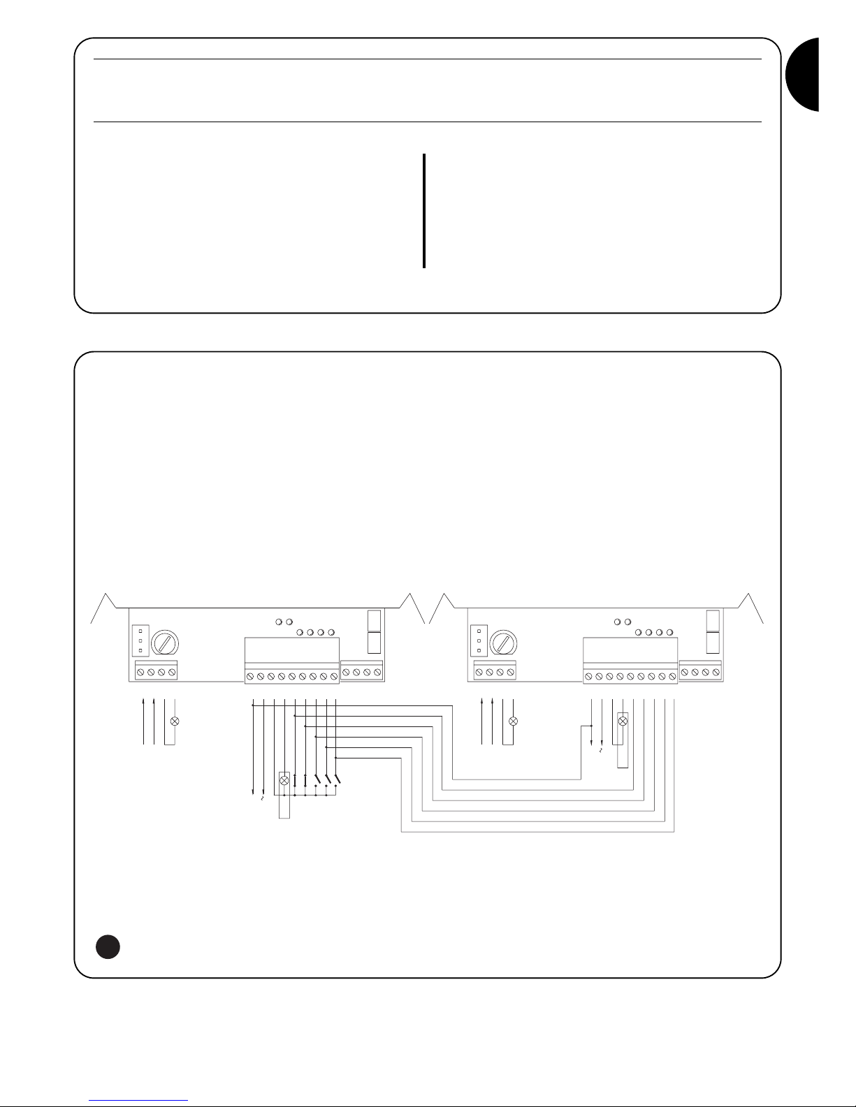
To create an automation system working with 2 opposed leafs:
• Use two motors with the control units connected as indicated in
fig. 5.
• Connect the flashing light and the “Gate Open Indicator” to any
one of the two control units .
• The inputs must be connected in parallel.
• The “Common” of the inputs can be connected to one of the 2
control units.
• Connect the 0Volts (Terminal 5) of the two control units.
• The “Phototest” function must not be used
• The “Condominium” function ( Dip-Switch 3) should be fitted as
this allows the leafs to be resynchronised if the 2 control units
become unsynchronised.
7) Using 2 control units on opposed leafs
44
43
42
41
121011
13
86759
4
312
24 V
200mA
COM
SCA
CLOSE
OPEN
STEP-BY-STEP
444243
131112
41
FCC
PHOTO
CLOSE
OPEN
STEP-BY-STEP
PHOTO
FCA
FCC
FCA
97856
10
423
1
CLOSE
STEP-BY-STEP
OPEN
STOP
COM
SCA
200mA
24 V
PHOTO
FLASHING LIGHT
POWER
INPUT
FLASHING
LIGHT
POWER
INPUT
Switch 10: On
ROBO - THOR
Without the PIU board fitted:
• Gate open indicator with proportional flashing
With the PIU board fitted:
• “Phototest”
OTTO
Without the PIU board fitted:
• Courtesy light time = 4 minutes
With the PIU board fitted:
• “Phototest”
5

14
“PIU” Card
The control unit is already fitted with all the functions used in a normal installation. In order to allow the system to be used in special installations, an optional card called “PIU” has been produced which adds new functions such as traffic light signalling, courtesy light, electric
locking, “Photocell2”, partial opening and “Phototest”.
Red = Red traffic light
This is normally always off and switches on when
the gate moves.
Green = Green traffic light
This is normally on and switches off when the
gate moves
Electric lock = Output for electric lock command.
The electric lock is activated for 1.5 s. at the start
of the opening movement.
Courtesy light/
Phototest = Output that if used to control the courtesy light,
turns on a courtesy light at the beginning of each
movement which remains on after the movement
has finished for a time programmed with the
T.Cor. trimmer on the “PIU” board.
If the “Phototest” function is activated (DipSwitch 10 = ON) this output allows the
photocells to be tested at the beginning of each
manoeuvre.
Partial open = Input for partial opening (Partial Open, Stop,
Close, Stop). This performs the same function as
the “Step-by-Step” on the main board, with the
difference that the open manoeuvre lasts for the
time set up on the T.AP.P. trimmer on the “PIU”
board.
Photo 2 = 2nd safety device input. This safety device cuts
in just during the opening manoeuvre causing
the gate to stop and eventually close if a
“Semiautomatic” or “Automatic” operation mode
is programmed on the control unit.
24 V = 24V output used to power services such as
photocells or the like. Terminal 11 is also the
common for the inputs.
“RADIO” Card
The control unit features a connector for plugging in a radio card, produced by Nice, which activates the “Step-by-Step” input and allows
the control unit to be remote-controlled with a transmitter.
8) Accessories
The control unit, being electronic, needs no particular maintenance.
However, periodically make sure (at least once every six months) that
the device adjusting motor force is in perfect working order; adjust
with the trimmer if necessary.
Carry out the whole test phase again to check that the limit switches,
safety devices (photocells, pneumatic edges, etc.) and the flashing
light are in perfect working order.
9) Maintenance
This product is made from various kinds of material, some of which
can be recycled.
Make sure you recycle or dispose of the product in compliance with
current laws and bye-laws.
Some electric components may contain polluting
substances; do not dump them.
!
10) Disposal

GB
15
This section will help fitters to solve some of the most common
problems that may arise during installation.
No LED is on:
• Check whether the control unit is powered (check mains voltage
is present at terminals 1-2 and a voltage of approx. 24Vac at
terminals 5-6).
• Check the 2 mains fuses have not blown; if none of the Led’s is
on a serious fault has probably occurred and the control unit
should therefore be replaced.
The OK LED flashes regularly but the INPUT Led’s do not
reflect the state of the respective inputs
• Carefully check the connections on input terminals 7-13.
The manoeuvre does not start
• Check that the Led’s of the “Stop” (FCA + FCC), “Photo” and
“Photo2”, if installed, safety device are on and that the relative
command Led that is activated (“Step-By-Step”, “Open” or
“Close”) remains on for the whole duration of the command.
The gate changes direction during a manoeuvre
An inversion is caused by:
• The photocells triggering (“Photo2” during the opening
manoeuvre, or “Photo” during the closing manoeuvre); in this
case, check the connections of the photocells and check the
input Led’s.
11) What to do if .…
Mains power input : 230 Vac 50/60 Hz
Versions /V1 : 120 Vac 50/60 Hz
Max. current for 24V services : 200mA
Flashing lamp output : For flashing lamps at mains voltage, maximum power 40 W
Gate open indicator output “SCA” : For indicator lamps at 24 Vac, maximum power 2 W
Operating temperature : -20 ÷ 70 °C
Working Time on ROBO/THOR : Adjustable from 2.5 to >60 s, or from <50 a to >120 s with TLM
Working Time on OTTO : Adjustable from 2.5 to >20 s, or from <20 to >40 s with TLM
Pause Time : Adjustable from 5 to > 160 s.
On the PIU card
Partial opening time ROBO/THOR : Adjustable from 1 to > 30 s.
Partial opening time OTTO : Adjustable from 1 to > 14 s.
Courtesy light time : Adjustable from 1 to > 180 s.
12) Technical specifications

16
centrale comando
motoriduttori
robo, thor, otto
Avvertenze:
Il presente manuale è destinato solamente al personale
tecnico qualificato per l'installazione. Nessuna informazione
contenuta nel presente fascicolo può essere considerata
d’interesse per l'utilizzatore finale!
Questo manuale è riferito solo a questa centrale e non deve
essere utilizzato per prodotti diversi.
Si consiglia di leggere attentamente tutte le istruzioni, almeno una
volta, prima di procedere con l’installazione.
!
Indice: pag.
1 Descrizione del prodotto 17
2 Installazione 18
2.1 Impianto tipico 18
2.2 Collegamenti elettrici 18
2.2.1 Schema elettrico 19
2.2.2 Descrizione dei collegamenti 19
2.2.3 Fototest 20
2.2.4 Verifica dei collegamenti 21
3 Regolazioni 21
4 Collaudo 22
5 Modi di funzionamento 23
pag.
6 Funzioni programmabili 23
6.1 Descrizione delle funzioni 24
7 Utilizzo di 2 centrali su ante contrapposte 25
8 Accessori Opzionali 26
9 Manutenzione 26
10 Smaltimento 26
11 Cosa fare se… 27
12 Caratteristiche tecniche 27

I
17
1) Descrizione del prodotto:
Questa centrale per l’automazione di cancelli e porte automatiche,
permette di comandare i motoriduttori ROBO, THOR, OTTO, in
corrente alternata monofase.
A seconda del tipo di motoriduttore da comandare, la centrale
presenta delle differenze, quali ad esempio: “Regolazione di Forza”,
“Spia Cancello Aperto” e “Luce di Cortesia”.
Sono presenti inoltre una serie di funzioni selezionabili tramite dei
Dip-Switch (mini selettori) e delle regolazioni effettuabili con dei
Trimmer.
Dei Led posti vicino agli ingressi ne segnalano lo stato; un ulteriore
Led presente vicino al microprocessore, segnala il corretto
funzionamento della logica interna.
Per facilitare il riconoscimento delle parti, in fig.1 sono indicati i
componenti più significativi.
Codice Prodotto* Codice Centrale di Comando* Funzione Aggiuntiva
ROBO
RO1000
RO1020
ROA3 Trimmer di “Regolazione Forza”
RO1010 ROA4 Relè “Spunto”
THOR
TH1551 THA5 Trimmer di “Regolazione Forza”
TH2251 THA6 Relè “Spunto”
OTTO OT21 OTA1 Uscita “Luce di Cortesia”
* = aggiungere al codice V1 per versione a 120 V 50/60 Hz
LMNOP
J
QRST
VU
I
X
W
Y
H
G
FZ
EDCBA
CH
P. P.
AP
FOTO
FCA
FCC
OK
Dip-Switch di selezione delle funzioni
Trimmer di “Regolazione Forza”
Trimmer di regolazione Tempo Lavoro (TL)
Trimmer di regolazione Tempo Pausa (TP)
Morsettiera per Antenna e 2° canale
Innesto scheda RADIO
Led di segnalazione stato ingressi
Morsettiera Ingressi / Uscite di comando
Relè “Comune”
Morsettiera alimentazione / Lampeggiante
Connettore primario trasformatore
Fusibile di linea (5A)
Connettore uscita “Luce di Cortesia” (solo su OTTO)
Uscita alimentazione motore
Connettore innesto condensatore
Relè “Spunto”
Triac “Luce di Cortesia” (solo su OTTO)
Triac “Chiude”
Triac “Apre”
Connettore secondario trasformatore
Ingresso finecorsa FCA / FCC
Fusibile di bassa tensione (500mA)
Innesto scheda PIU
Led OK
Microprocessore
A
B
C
D
E
F
G
H
I
J
L
M
N
O
P
Q
R
S
T
U
V
W
X
Y
Z
1

18
2.1) Impianto tipico
Per chiarire alcuni termini ed alcuni aspetti di un impianto di automazione per porte o cancelli, riportiamo un esempio tipico.
ROBO e THOR OTTO
1) Coppia fotocellule “Foto”
2) Lampeggiante
3) Selettore a chiave
4) Costa pneumatica
5) Coppia fotocellule “Foto 2”
In particolare ricordiamo che:
• Tutte le fotocellule prodotte da Nice dispongono del sistema di sincronismo che permette di eliminare il problema dell’interferenza
tra due coppie di fotocellule (per altri particolari vedere le istruzioni delle fotocellule)
• La coppia di fotocellule “Foto” in apertura non ha effetto mentre provoca una inversione durante la chiusura.
• La coppia di fotocellule “Foto2” in chiusura non ha effetto mentre provoca una inversione durante l’apertura.
2.2) Collegamenti elettrici
Per garantire l'incolumità dell'operatore e per prevenire
danni ai componenti, mentre si effettuano i collegamenti o
si innestano le varie schede la centrale deve essere
assolutamente spenta.
• Alimentare la centrale attraverso un cavo da 3 x 1,5mm
2
. Se la
distanza fra la centrale e la connessione all'impianto di terra
supera i 30m è necessario prevedere un dispersore di terra in
prossimità della centrale.
• Nei collegamenti della parte a bassissima tensione di sicurezza
usare cavetti di sezione minima pari a 0,25mm
2
.
• Usare cavetti schermati se la lunghezza supera i 30m collegando
la calza a terra solo dal lato della centrale.
• Evitare di fare connessioni ai cavi in casse interrate anche se
completamente stagne.
• Gli ingressi dei contatti di tipo Normalmente Chiuso (NC), se non
usati, vanno ponticellati con “comune 24V” esclusi gli ingressi
delle fotocellule nel caso sia inserita la funzione di “Fototest”. Per
ulteriori chiarimenti vedere paragrafo “Fototest”.
• Se per lo stesso ingresso ci sono più contatti (NC) vanno posti in
serie tra di loro.
• Gli ingressi dei contatti di tipo Normalmente Aperto (NA) se non
usati vanno lasciati liberi.
• Se per lo stesso ingresso ci sono più contatti (NA) vanno posti in
parallelo tra di loro.
• I contatti devono essere assolutamente di tipo meccanico e
svincolati da qualsiasi potenziale, non sono ammessi
collegamenti a stadi tipo quelli definiti "PNP", "NPN", "Open
Collector" ecc.
!
Ricordiamo che gli impianti di cancelli e porte automatiche
devono essere installati solo da personale tecnico qualificato e
nel pieno rispetto delle norme di legge. Seguire attentamente
le indicazioni del fascicolo : “Avvertenze per l’installatore”.
!
2) Installazione:
2a
2b
FOTO
FOTO
FOTO 2
5
3
2
1
3
4
FOTO
2
1

I
19
2.2.1) Schema elettrico
2.2.2) Descrizione dei collegamenti
Riportiamo una breve descrizione dei possibili collegamenti della centrale verso l’esterno.
Morsetti Funzione Descrizione
1-2 : Alimentazione = Linea di alimentazione da rete
3-4 : Lampeggiante = Uscita per collegamento del lampeggiante a tensione di rete ( Max. 40W)
5-6 : 24 Vac = Alimentazione servizi 24Vac (Foto, Radio, ecc.) Max 200mA
7 : Comune = Comune per tutti gli ingressi
8 : Spia C.A. (SCA) = “Spia Cancello Aperto” 24Vac max. 2W ( Non presente su versione OTTO)
9 : Alt = Ingresso con funzione di arresto della manovra con breve inversione del moto
10 : Foto = Ingresso per dispositivi di sicurezza (fotocellule, coste pneumatiche)
11 : Passo-Passo (PP) = Ingresso per movimento ciclico (“Apre” - “Stop” - “Chiude” - “Stop”)
12 : Apre = Ingresso per movimento in apertura
13 : Chiude = Ingresso per movimento in chiusura
41-42 : 2° Ch Radio = Uscita dell’eventuale secondo canale del ricevitore radio
43-44 : Antenna = Ingresso per antenna del ricevitore radio
3

20
2.2.3) Fototest
Il “Fototest”, aumenta l’affidabilità dei dispositivi di sicurezza;
permettendo di raggiungere la “categoria 2” secondo la norma UNI
EN 954-1 (ediz. 12/1998) per quanto riguarda l’insieme centrale e
fotocellule di sicurezza.
Ogni volta che viene avviata una manovra vengono controllati i
dispositivi di sicurezza coinvolti; solo se tutto è a posto la manovra
ha inizio. Se invece il test non dà esito positivo (fotocellula accecata
dal sole, cavi in corto circuito, ecc.) viene individuato il guasto e la
manovra non viene eseguita.
Per ottenere la funzione “Fototest” è necessario:
• Utilizzare la scheda aggiuntiva PIU.
• Impostare il Dip-Switch 10 ON
• Realizzare una particolare configurazione nei collegamenti dei
dispositivi di sicurezza come in fig.4a che prevede di collegare
l’alimentazione dei trasmettitori delle fotocellule non direttamente
dall’uscita dei servizi, ma interrompendo tale alimentazione
passando per i morsetti 7 e 8 della scheda PIU. La corrente
massima utilizzabile sull’uscita “Fototest” della scheda PIU è di
100mA (2 coppie di fotocellule Nice)
• Alimentare i ricevitori direttamente dall’uscita servizi della
centrale (morsetti 5-6).
Se in un secondo momento non si desiderasse più utilizzare la funzione
di Fototest, sarà necessario abbassare il Dip-Switch 10 e modificare la
configurazione dei collegamenti come indicato nella fig.4b.
Il test delle fotocellule avviene in questo modo: quando è richiesto un
movimento, in primo luogo viene controllato che tutti i ricevitori
interessati dal movimento diano il consenso, poi viene spenta
l’alimentazione ai trasmettitori e quindi verificato che tutti i ricevitori
segnalino il fatto togliendo il loro consenso; infine viene riattivata
l'alimentazione dei trasmettitori e quindi nuovamente verificato il
consenso da parte di tutti i ricevitori. Solo se questa sequenza ha
esito positivo, la manovra verrà avviata.
È sempre bene inoltre attivare il sincronismo attraverso il taglio degli
appositi ponticelli sui trasmettitori; questo è l'unico metodo per
garantire che due coppie di fotocellule non interferiscano tra loro.
Verificare sul manuale delle fotocellule le istruzioni per il
funzionamento sincronizzato.
Nel caso un ingresso sottoposto a “Fototest” non venga utilizzato
(Esempio “Foto2”) e si desideri comunque la funzione fototest
occorre ponticellare l’ingresso non usato come indicato in fig.4c.
13
9107
658
(Scheda PIU)
9
8
10
11
12
7
78
9
11
10
12
(Scheda PIU)
13
9107
658
109
8
13
7
6
5
710PIU
PIU
811PIU
PIU
PIU 8
RX
43512
6
FOTO
5
10
7
RX
543
FOTO 2
21
6
5
(scheda PIU)
7
RX
54321
6
FOTO
RX
10
7
(scheda PIU)
FOTO 2
5
10PIU
6
7
5312 4
5
RX
34 512
6
10
7
5
FOTO
10PIU
PIU 11
RX
12
7
12
PIU
PIU
21
34 512
RX
53412
87
TX
10
12
11
9
(Scheda PIU)
12
TX
21
FOTO 2
FOTO
(scheda PIU)
7
PIU
21
RX
423 5
6
5
5
6
21
RX
2345
TX
FOTO
21
TX
(scheda PIU)
FOTO 2
12
1
1
12
712PIU
PIU
RX
34 512
TX
12
FOTO
12
PIU
TX
TX
TX
TX
TX
“Foto” e “Foto2” con “Fototest”
“Foto” e “Foto2” senza “Fototest”
“Foto” con “Fototest”
4a
4b
4c

I
21
2.2.4) Verifica dei collegamenti
Le prossime operazioni vi porteranno ad agire su circuiti sotto
tensione. La maggior parte dei circuiti sono sottoposti a bassissima
tensione di sicurezza e quindi non pericolosa, alcune parti sono
sottoposte a tensione di rete quindi ALTAMENTE PERICOLOSE!
Prestate la massima attenzione a ciò che fate e NON OPERATE
MAI DA SOLI!
• Alimentare la centrale e subito verificare che tra i morsetti 5-6 vi
siano circa 24Vac.
• Verificare che, dopo pochi istanti di lampeggio veloce, il Led
“OK” lampeggi ad una cadenza regolare.
•
Ora verificare che i Led relativi agli ingressi con contatti tipo (NC) siano
accesi (tutte le sicurezze attive) e che i Led relativi ad ingressi tipo (NA)
siano spenti (nessun comando presente). Se questo non avviene
controllare i collegamenti e l’efficienza dei vari dispositivi. L’ingresso di
“Alt” interviene spegnendo sia il finecorsa FCA che FCC.
• Verificare l’esatto collegamento dei finecorsa; muovere la leva del
finecorsa e verificare che il relativo finecorsa intervenga
spegnendo il corrispondente led sulla centrale.
• Sbloccare l’anta e portarla a metà della corsa, poi bloccare. In
questo modo l’anta è libera di muoversi sia in apertura che in
chiusura.
•
Ora bisognerà verificare se il movimento avviene nella direzione
corretta, cioè controllare la corrispondenza tra il movimento
previsto dalla centrale e quello effettivo delle ante. Questa verifica è
fondamentale, se la direzione è sbagliata in alcuni casi (ad esempio
in modo “Semiautomatico”) l’automatismo potrebbe in apparenza
funzionare regolarmente, infatti il ciclo “Apre” è simile al ciclo
“Chiude”, con la fondamentale differenza che i dispositivi di
sicurezza verranno ignorati nella manovra di “Chiude”, che
normalmente è la più pericolosa, ed interverranno in apertura
provocando una richiusura addosso all’ostacolo con effetti
disastrosi!
• Per verificare che il senso di rotazione sia esatto è sufficiente
dare un breve impulso sull’ingresso PP; la prima manovra che la
centrale esegue dopo essere stata alimentata è sempre “Apre”,
quindi è sufficiente verificare che l’automatismo si muova nel
senso dell’apertura. Nel caso il movimento sia avvenuto in senso
errato occorre:
Spegnere alimentazione
Ruotare di 180° il connettore di alimentazione del motore
e quello dei finecorsa. (Rif. “O” e rif. “V” di fig.1)
Eseguito quanto descritto, riprovare se il senso di rotazione
è corretto ripetendo l’ultimo punto.
Il Led “OK” posizionato al centro della scheda, ha il compito di
segnalare lo stato della logica interna: un lampeggio regolare ed alla cadenza
di 1 secondo indica che il microprocessore interno è attivo ed è in attesa di
comandi. Quando invece lo stesso microprocessore riconosce una variazione
dello stato di un ingresso (sia ingresso di comando che Dip-Switch delle
funzioni) genera un doppio lampeggio veloce, questo anche se la variazione
non provoca effetti immediati. Un lampeggio molto veloce per 3s. indica che
la centrale è appena stata alimentata e sta eseguendo un test delle parti
interne; infine un lampeggio non costante indica che il test non è andato a
buon fine e quindi c’è un guasto.
!
Le regolazioni sono effettuabili attraverso dei Trimmer che agiscono
modificando i seguenti parametri:
Tempo Lavoro (TL):
Regola la durata massima della manovra di apertura o chiusura.
Per la regolazione del TL, selezionare il modo di funzionamento
“Semiautomatico” ponendo in ON il Dip-Switch 1 quindi regolare il
Trimmer TL a metà corsa. Con queste regolazioni eseguire un ciclo
di apertura e di chiusura ed eventualmente intervenire sulla
regolazione del Trimmer TL in modo tale che sia sufficiente ad
eseguire tutta la manovra e rimanga ancora un margine di 2s. o 3s.
Nel caso in cui anche ponendo il Trimmer TL al massimo non si
ottenga un tempo sufficiente, tagliare il ponticello TLM, posto sullo
stampato tra i Trimmer TL e TP, in modo da ottenere un Tempo
Lavoro Maggiorato (TLM).
Tempo Pausa (TP):
Nel funzionamento “Automatico” regola il tempo tra il termine della
manovra di apertura e l’inizio della manovra di chiusura.
Per la regolazione del TP, selezionare il modo di funzionamento
“Automatico” spostando in ON il Dip-Switch 2, quindi regolare il
Trimmer TP a piacere. Per la verifica occorre eseguire una manovra
di apertura, quindi controllare il tempo che trascorre prima della
richiusura “Automatica”.
Forza (F):
Presente sulla centrale di comando per permette di regolare il valore
della “Forza” massima.
Particolare attenzione deve essere posta nella regolazione del
Trimmer “Forza”, perché questa regolazione può influire sul grado di
sicurezza dell’automazione. Per la regolazione occorre procedere
per tentativi successivi misurando la forza applicata dall’anta e
comparandola con quanto previsto dalle normative.
Nelle centrali per RO1010 e OT21 la “Forza” viene regolata
attraverso un selettore a più posizioni posto sul contenitore del
trasformatore di alimentazione della centrale.
3) Regolazioni:
TP
TL
F
TLM

22
Terminate le verifiche e le regolazioni è possibile passare al collaudo dell’impianto.
Il collaudo dell’automazione deve essere eseguito da personale qualificato ed esperto che dovrà farsi carico di
stabilire le prove previste in funzione del rischio presente.
Il collaudo è la parte più importante di tutta la realizzazione dell’automazione. Ogni singolo componente, ad esempio motoriduttore, arresto
di emergenza, fotocellule ecc. può richiedere una specifica fase di collaudo e per questo si consiglia di seguire le procedure riportate nei
rispettivi manuali di istruzioni.
Per il collaudo della centrale eseguire la seguente sequenza di operazioni:
1. Selezione funzioni:
• Impostare ON il Dip-Switch 1 (Funzionamento “Semiautomatico”)
• Se si sono realizzati i collegamenti di fig.4a per l’utilizzo della funzione di “Fototest” (se presente scheda PIU), impostare ON il
Dip-Switch 10 (Funzione “Fototest”).
• Impostare OFF tutti gli altri Dip-Switch
2. Premere e il tasto di comando “Apre” oppure “Passo-Passo” e verificare che:
• si attivi il lampeggiante
• inizi una manovra di apertura
• il movimento si arresti, al raggiungimento del finecorsa di apertura FCA.
3. Premere il tasto di comando “Chiude” oppure “Passo-Passo” e verificare che:
• si attivi il lampeggiante
• parta una manovra di chiusura
• il movimento si arresti, al raggiungimento del finecorsa di chiusura FCC
4. Far partire una manovra di apertura e verificare che durante la manovra l’intervento di un dispositivo:
• Collegato all’ingresso “Alt”, provochi l’arresto con breve inversione del moto
• Collegato all’ingresso “Foto”, non abbia nessun effetto
• Collegato all’ingresso “Foto2”, provochi la fermata e l’inversione della manovra (se presente scheda PIU)
5. Far partire una manovra di chiusura e verificare che durante la manovra l’intervento di un dispositivo:
• Collegato all’ingresso “Alt”, provochi l’arresto con breve inversione del moto
• Collegato all’ingresso “Foto”, provochi la fermata e l’inversione della manovra
• Collegato all’ingresso “Foto2”, non abbia nessun effetto (se presente scheda PIU)
6. Sugli ingressi collegati, verificare che l’attivazione dell’ingresso provochi un passo nella sequenza:
• Ingresso “Passo-Passo”: Sequenza = “Apre” – “Stop” – “Chiude” – ”Stop”
• Ingresso “Apre”: Sequenza = “Apre” – “Stop” – “Apre” – “Stop”
• Ingresso “Chiude”: Sequenza = “Chiude” – “Stop” - “Chiude” – “Stop”
• Ingresso “Apre Parziale”: Sequenza = “Apre Parziale” – “Stop” – “Chiude” – “Stop” (se presente scheda PIU).
7 Se si utilizza la funzione “Fototest” verificare l’efficienza del test (se presente scheda PIU):
• Interrompere la fotocellula “Foto”, quindi far partire una manovra e verificare che questa non venga eseguita
• Interrompere la fotocellula “Foto2”, quindi far partire una manovra e verificare che questa non venga eseguita
• Cortocircuitare il contatto della fotocellula “Foto”, quindi far partire una manovra e verificare che questa non venga eseguita
• Cortocircuitare il contatto della fotocellula “Foto2”, quindi far partire una manovra e verificare che questa non venga eseguita
8. Eseguire le prove per la rilevazione delle “Forze” di Impatto come previsto della EN 12445.
Se al termine del collaudo vengono attivate ulteriori funzioni programmabili che possono ridurre la sicurezza dell’impianto, è necessario
effettuare un collaudo specifico di tali funzioni.
!
4) Collaudo

I
23
5) Modi di funzionamento
Nel funzionamento in modo manuale, l’ingresso “Apre” consente il
movimento in apertura, l’ingresso “Chiude” consente il movimento in
chiusura. Il “Passo-Passo” consente il movimento alternativamente
in apertura e in chiusura.
Non appena cessa il comando in ingresso, il movimento si arresta.
In apertura il movimento si arresta quando intervengono i finecorsa
oppure se manca il consenso dalla “Foto2” (su scheda PIU); in
chiusura invece il movimento si arresta se manca il consenso di
“Foto”. Sia in apertura che in chiusura un intervento su “Alt” provoca
sempre un immediato arresto del movimento. Una volta che un
movimento si è arrestato è necessario far cessare il comando in
ingresso prima che un nuovo comando possa far iniziare un nuovo
movimento.
Nel funzionamento in uno dei modi automatici (“Semiautomatico”,
“Automatico” o “Chiude Sempre”) un impulso di comando
sull’ingresso “Apre” provoca il movimento in apertura. Un impulso su
“Passo-Passo” provoca alternativamente apertura o chiusura. Un
secondo impulso sul “Passo-Passo” o sullo stesso ingresso che ha
iniziato il movimento provoca uno “Stop”.
Sia in apertura che in chiusura un intervento su “Alt” provoca un
immediato arresto del movimento.
Se in un ingresso di comando invece di un impulso viene mantenuto
un segnale continuo si provoca uno stato di “prevalenza” in cui gli
altri ingressi di comando rimangono disabilitati (utile per collegare
un orologio o un selettore Notte-Giorno).
Nel caso fosse selezionato il modo di funzionamento automatico,
dopo una manovra di apertura, viene eseguita una pausa, al termine,
viene eseguita una chiusura. Se durante la pausa vi fosse un
intervento di “Foto”, il temporizzatore verrà ripristinato con un nuovo
Tempo Pausa; se invece durante la pausa si interviene su “Alt” la
funzione di richiusura viene cancellata e si passa in uno stato di
“Stop”.
In apertura l’intervento di “Foto” non ha alcun effetto mentre la
“Foto2” (su scheda PIU) provoca l’inversione del moto; in chiusura
l’intervento di “Foto” provoca una inversione del moto, poi una
pausa, quindi una richiusura.
La centrale dispone di una serie di microinterruttori che permettono
di attivare varie funzioni al fine di rendere l’impianto più adatto alle
esigenze dell’utilizzatore e più sicuro nelle varie condizioni d’uso. Le
funzioni si attivano ponendo il relativo dip-switch in posizione “On”
mentre non sono inserite con il corrispondente Dip-Switch in “Off”.
Alcune delle funzioni programmabili sono legate ad
aspetti della sicurezza. Valutare con molta attenzione gli
effetti di ogni funzione, verificando quale sia quella che
dia la maggior sicurezza possibile.
!
I Dip-Switch permettono di selezionare i vari modi di funzionamento e di inserire le funzioni desiderate secondo la seguente tabella:
Switch 1-2: Off-Off = Movimento “Manuale” cioè uomo presente
On -Off = Movimento “Semiautomatico”
Off-On = Movimento “Automatico” cioè chiusura automatica
On -On = Movimento “Automatico” + Chiude Sempre
Switch 3: On = Funzionamento Condominiale < non disponibile in modo manuale >
Switch 4: On = Prelampeggio
Switch 5: On =
Richiudi 5 s. dopo “Foto” < se in “Automatico” > o Chiudi dopo Foto < se in “Semiautomatico” >
Switch 6: On = Sicurezza “Foto” anche in apertura
Switch 7: On = Partenza graduale
Switch 8: On = Rallentamento
Switch 9: On = Freno
Switch 10: (su Robo) On = Spia Cancello Aperto (SCA) con lampeggio proporzionale
Senza scheda PIU
(su Otto) On = Tempo luce di cortesia = 4 minuti
Con scheda PIU On = Funzione “Fototest”
NOTA: Alcune funzioni sono possibili solo in determinate condizioni; queste sono segnalate con le note tra i caratteri “<...>”.
6) Funzioni programmabili
101

24
6.1) Descrizione delle funzioni
Riportiamo ora una breve descrizione delle funzioni che si possono inserire portando in “On” il relativo Dip-Switch
Switch 1-2: Off-Off = Movimento “Manuale” (uomo presente)
On-Off = Movimento “Semiautomatico”
Off-On = Movimento “Automatico” (chiusura automatica)
On-On = Movimento “Automatico” + “Chiude Sempre”
Nel funzionamento “Manuale” il movimento viene eseguito solo fino alla presenza del comando (tasto premuto).
In “Semiautomatico” basta un impulso di comando per far eseguire tutto il movimento fino allo scadere del Tempo Lavoro o al
raggiungimento del finecorsa. Nel funzionamento in modo “Automatico”, dopo una apertura viene eseguita una pausa, quindi la chiusura
avviene automaticamente.
La funzione “Chiude Sempre” interviene dopo una mancanza di alimentazione; se viene rilevato il cancello aperto si avvia automaticamente
una manovra di chiusura preceduta da 5 secondi di prelampeggio.
Switch 3: On = Funzionamento Condominiale (non disponibile in modo manuale)
Nel funzionamento condominiale, una volta avviato un movimento in apertura la manovra non può essere interrotta da altri impulsi di
comando su “Passo-Passo” o “Apre” fino alla fine del movimento in apertura.
Nel movimento in chiusura un nuovo impulso di comando provoca l’arresto e l’inversione del movimento in apertura.
Switch 4: On = Prelampeggio
All’impulso di comando viene prima attivato il lampeggiante poi, dopo 5s. (2s. se in “Manuale”), inizia il movimento.
Switch 5: On = Richiudi 5 s. dopo Foto < se in “Automatico” > o Chiudi dopo Foto < se in “Semiautomatico” >
Questa funzione, se in “Automatico” permette di tenere il cancello aperto solo per il tempo necessario al transito, infatti al termine
dell’intervento di “Foto” la manovra si arresta. Dopo 5s. partirà automaticamente una manovra di chiusura. Se in “Semiautomatico”, un
intervento di “Foto” nella manovra di chiusura attiva la chiusura automatica con il Tempo Pausa regolato.
Switch 6: On = Sicurezza “Foto” anche in apertura
Normalmente la sicurezza “Foto” è attiva solo nella manovra di chiusura, se lo Dip-Switch 6 viene posto su "On" l'intervento del dispositivo
di sicurezza provoca una interruzione del movimento anche in apertura.
Se in “Semiautomatico” o “Automatico” si avrà la ripresa del moto in apertura subito dopo il disimpegno.
Switch 7: On = Partenza graduale
Esegue l’inizio del movimento in modo graduale evitando gli indesiderati scossoni dell’automazione
Switch 8: On = Rallentamento
Il rallentamento consiste in una riduzione della velocità al 30% della velocità nominale in modo da evitare inutili scossoni alla fine della
manovra.
La funzione di rallentamento oltre che diminuire la velocità dell’automazione riduce del 70% la coppia del motore.
In automazioni che richiedono una coppia elevata, questa riduzione potrebbe provocare l’arresto immediato del motore.
Versione per ROBO e THOR:
Al termine della manovra di apertura o chiusura dovuta al termine del
Tempo Lavoro, viene eseguita una fase di rallentamento che dura
quanto il Tempo Lavoro.
Se la manovra termina per intervento dei finecorsa la fase di
rallentamento non viene eseguita; occorre quindi regolare il Tempo
Lavoro affinché inizi il rallentamento 30-50cm prima dell’intervento
dei finecorsa.
Versione per OTTO:
Al termine della manovra di chiusura la fase di rallentamento dura 3 s.
se innescata dall’intervento dei finecorsa, quanto il Tempo Lavoro se
innescata dal termine del Tempo Lavoro (per un buon funzionamento
del rallentamento è consigliato l’uso dei finecorsa.)
Nella manovra di apertura non viene eseguito il rallentamento ma
una fermata graduale.
Nel caso si utilizzi la funzione di rallentamento su
installazioni sensibili e se questa duri più di 3 s. è
necessario inserire sui morsetti di alimentazione da rete
!
in prossimità della centrale un filtro di rete da almeno 6A
con attenuazione di 30dB per non superare i limiti di
emissione elettromagnetica dettati dalla norma EN 50081-1
.

I
25
Switch 9: On = Freno
Al termine del movimento viene eseguita una procedura di freno al motore, inizialmente blanda poi più incisiva in modo da fermare il cancello
velocemente ma senza scossoni.
Questa funzione permette di eseguire ad ogni inizio manovra un controllo dell’efficienza delle fotocellule. Vedere capitolo “Fototest”.
Per realizzare una automazione con 2 ante che lavorano in modo
contrapposto è necessario:
• Usare due motori con le centrali collegate come indicato nella
fig.5.
• Collegare il lampeggiante e la “Spia Cancello Aperto” indifferen-
temente ad una delle due centrali.
• Gli ingressi devono essere posti in parallelo tra loro.
• Il “Comune” degli ingressi può essere collegato ad una delle 2
centrali.
• Collegare assieme i 0Volt (Morsetto 5) delle due centrali.
• Non deve essere utilizzata la funzione “Fototest”.
• È opportuno inserire la funzione “Condominiale” (Dip-Switch 3)
che permette di risincronizzare le ante qualora le 2 centrali
perdano il sincronismo.
7) Utilizzo di due centrali su ante contrapposte
Switch 10: On
ROBO e THOR
Senza scheda PIU inserita:
• “Spia Cancello Aperto” con lampeggio proporzionale
Con scheda PIU inserita:
• “Fototest”
OTTO
Senza scheda PIU inserita:
• Tempo “Luce di Cortesia” = 4 minuti
Con scheda PIU inserita:
• “Fototest”
5

26
Scheda PIU
La centrale contiene già tutte le funzioni che vengono utilizzate in una normale installazione. Per sopperire alle richieste di utilizzo in
impianti particolari, è stata predisposta una scheda opzionale PIU che permette di aggiungere nuove funzioni quali segnalazione semaforica, luce di cortesia, Elettroserratura, “Foto2”, apertura parziale e “Fototest”.
Rosso = Luce rossa del semaforo
È normalmente sempre spenta, si accende
durante il movimento del cancello
Verde = Luce verde del semaforo
Rimane normalmente accesa, si spegne durante
il movimento del cancello
Elettroserratura = Uscita per comando elettroserratura.
L'elettroserratura viene attivata per 1,5 s. all'inizio
del movimento in apertura.
Luce Cortesia/
Fototest = Uscita che se utilizzata per il comando luce di
cortesia, consente di accendere all'inizio di ogni
movimento una Luce di Cortesia che rimane
accesa oltre il termine del movimento anche per
il tempo programmato con il Trimmer Tempo
Luce di Cortesia presente sulla scheda PIU.
Se si attiva la funzione “Fototest” (Dip-Switch 10
= ON) questa uscita consente di eseguire un test
delle fotocellule ad inizio manovra.
Apre parziale = Ingresso per apertura parziale (“Apre” -
”Parziale”, “Stop”, “Chiude”, “Stop”). Esegue la
medesima funzione del “Passo-Passo” sulla
scheda principale, con la differenza che la
manovra di “Apre” dura per il tempo impostato
sul Trimmer “Tempo Apertura Parziale” presente
sulla scheda PIU.
Foto 2 = Ingresso 2° dispositivo di sicurezza. Questo
dispositivo interviene nella sola manovra di
apertura provocando un arresto del movimento,
con eventuale richiusura se sulla centrale è
programmato il modo di funzionamento
“Semiautomatico” o “Automatico” .
24 V = Uscita 24V utilizzabile per alimentazione i
servizi come fotocellule o altro. Il morsetto 11 è
anche il comune per gli ingressi .
Scheda RADIO
Nelle centrale è predisposto un connettore per l’inserimento di una scheda radio, Nice, che permette di agire sull’ingresso di “Passo-Passo” e comandare in questo modo la centrale a distanza tramite un trasmettitore.
8) Accessori opzionali
La centrale come parte elettronica, non necessita di alcuna
manutenzione particolare. Verificare comunque periodicamente
(almeno ogni 6 mesi), la perfetta efficienza e la regolazione del
dispositivo di regolazione della Forza del motore, eventualmente
agire sul trimmer di regolazione.
Rieseguire per intero la fase di collaudo per controllare la corretta
efficienza dei finecorsa, dei dispositivi di sicurezza (fotocellule, coste
pneumatiche, ecc.) del lampeggiante.
9) Manutenzione
Questo prodotto è costituito da vari tipi di materiali, alcuni possono
essere riciclati.
Informatevi sui sistemi di riciclaggio o smaltimento del prodotto
attenendovi alle norme di legge vigenti a livello locale.
Alcuni componenti elettrici potrebbero contenere
sostanze inquinanti, non disperdere nell’ambiente.
!
10) Smaltimento

I
27
Questa vuole essere una guida per aiutare l’installatore a risolvere
alcuni dei più comuni problemi che si possono presentare durante
l’installazione.
Nessun LED risulta acceso
• Verificare se la centrale è alimentata (verificare che sui morsetti
1-2 sia presente la tensione di rete e sui morsetti 5-6 una
tensione di 24Vac circa.)
•
Verificare se i 2 fusibili di alimentazione sono integri: se neppure in
questo caso nessun Led risulta acceso è probabile sia presente
un guasto grave e quindi la centrale dovrà essere sostituita.
IL Led OK lampeggia regolarmente ma i led INGRESSI non
rispecchiano lo stato dei rispettivi ingressi
• Verificare con attenzione i collegamenti sui morsetti degli
ingressi 7÷13.
La manovra non parte
• Verificare che i Led delle sicurezze “Alt” (FCA + FCC) , “Foto”, ed
eventualmente “Foto2” siano accesi e che il Led del comando
che viene attivato (“Passo-Passo”, “Apre” o “Chiude”) si accenda
per la durata del comando.
Durante il movimento il cancello effettua un’inversione
La causa che provoca un’inversione è:
• Un intervento delle fotocellule (“Foto2” in apertura, o “Foto”
durante la chiusura); controllare i collegamenti delle fotocellule ed
eventualmente verificare i Led di segnalazione degli ingressi.
11) Cosa fare se….
Alimentazione da rete : 230 Vac 50/60 Hz
Versioni /V1 : 120 Vac 50/60 Hz
Corrente Max servizi 24 V : 200mA
Uscita lampeggiante : Per lampeggianti a tensione di rete, potenza massima 40 W
Uscita spia cancello aperto “SCA” : Per lampade spia 24Vac, potenza massima 2 W
Temperatura di esercizio : -20 ÷ 70 °C
Tempo Lavoro ROBO/THOR : Regolabile da 2.5 a > 60 s, oppure da < 50 a > 120 s con TLM
Tempo Lavoro OTTO : Regolabile da 2.5 a > 20 s, oppure da < 20 a > 40 s con TLM
Tempo Pausa : Regolabile da 5 a > 160 s.
su Scheda PIU
Tempo Ap. Parziale ROBO/THOR : Regolabile da 1 a > 30 s.
Tempo Ap. Parziale OTTO : Regolabile da 1 a > 14 s.
Tempo luce di cortesia : Regolabile da 1 a > 180 s.
12) Caratteristiche tecniche

28
armoire de commande
opérateurs
robo, thor, otto
Recommandations:
Ce manuel est destiné exclusivement au personnel
technique qualifié pour l’installation. Aucune information
contenue dans ce fascicule ne peut être considérée comme
intéressante pour l’utilisateur final!
Ce manuel se réfère uniquement à cette armoire de
commande et ne doit pas être utilisé pour des produits
différents.
Nous conseillons de lire attentivement toutes les instructions, au moins
une fois, avant de procéder à l’installation.
!
Table des matières: page
1 Description du produit 29
2 Installation 30
2.1 Installation typique 30
2.2 Connexions électriques 30
2.2.1 Schéma électrique 31
2.2.2 Description des connexions 31
2.2.3 Photo-test 32
2.2.4 Vérification des connexions 33
3 Réglages 33
4 Essai de fonctionnement 34
5 Modes de fonctionnement 35
page
6 Fonctions programmables 35
6.1 Description des fonctions 36
7 Utilisation de 2 centrales sur battants 37
antagoniques
8 Accessoires en option 38
9 Maintenance 38
10 Mise au rebut 38
11 Que faire si… 39
12 Caractéristiques techniques 39

F
29
1) Description du produit:
Cette armoire de commande pour l’automatisation de portails et
portes automatiques, permet de commander les opérateurs ROBO,
OTTO, THOR en courant alternatif monophasé.
Suivant le type d’opérateur à commander, la logique de commande
présente des variantes, comme par exemple: “Réglage de la Force”,
“Voyant Portail Ouvert” et “Éclairage automatique”.
Elle inclut en outre une série de fonctions sélectionnables à l’aide de
“Dip-Switchs” (mini sélecteurs) et des réglages qui s’effectuent avec
des trimmers.
L’armoire contient des diodes électroluminescentes (Led) placées à
proximité des entrées qui en signalent l’état, une Led supplémentaire
se trouve près du microprocesseur et signale le fonctionnement
correct de la logique interne.
Pour faciliter l’identification des parties, la fig.1 indique les
principaux composants.
LMNOP
J
QRST
VU
I
X
W
Y
H
G
FZ
EDCBA
CH
P. P.
AP
FOTO
FCA
FCC
OK
Dip-Switch de sélection des fonctions
Trimmer de réglage Force
Trimmer de réglage Temps de Travail (TL)
Trimmer de réglage Temps de Pause (TP)
Bornier pour antenne et 2e canal
Connexion carte RADIO
Led de signalisation état entrées
Bornier Entrées/Sorties de commande
Relais “Commun”
Bornier alimentation / Clignotant
Connecteur primaire transformateur
Fusible de ligne (5A)
Connecteur sortie Éclairage Automatique (seulement sur OTTO)
Sortie alimentation moteur
Connecteur condensateur
Relais Démarrage
Triac Éclairage Automatique (seulement sur OTTO)
Triac “Ferme”
Triac “Ouvre”
Connecteur secondaire transformateur
Entrée microinterrupteur de fin de course FCA / FCC
Fusible de basse tension (500 mA)
Connexion carte PIU
Led OK
Microprocesseur
A
B
C
D
E
F
G
H
I
J
L
M
N
O
P
Q
R
S
T
U
V
W
X
Y
Z
1
Code Produit* Code Carte Electronique* Fonction Supplémentaire
ROBO
RO1000
RO1020
ROA3 Trimmer de réglage Force
RO1010 ROA4 Relais Démarrage
THOR
TH1551 THA5 Trimmer de réglage Force
TH2251 THA6 Relais Démarrage
OTTO OT21 OTA1 Sortie Éclairage Automatique
* = ajouter au code V1 pour version 120 V 50/60 Hz

30
2.1) Installation typique
Pour préciser certains termes et certains aspects d’un automatisme pour portes ou portails, nous donnons ci-après un exemple typique.
ROBO / THOR OTTO
1) Paire de photocellules “Photo”
2) Clignotant
3) Sélecteur à clé
4) Barre palpeuse
5) Paire de photocellules “Photo 2”
En particulier, nous rappelons que:
• Toutes les photocellules produites par Nice disposent du système de synchronisme qui permet d’éliminer le problème de
l’interférence entre deux paires de photocellules (pour plus de détails, voir les instructions des photocellules)
• La paire de photocellules “Photo” n’a pas d’effet en ouverture tandis qu’elle provoque une inversion durant la fermeture.
• La paire de photocellules “Photo2” n’a pas d’effet en fermeture tandis qu’elle provoque une inversion durant l’ouverture.
Nous rappelons que les automatismes de portails et portes
automatiques doivent être installés exclusivement par du
personnel technique qualifié et dans le plein respect des
normes légales. Suivre attentivement les recommandations du
fascicule : “Recommandations pour l’installateur”.
!
2) Installation:
2a
2b
PHOTO
PHOTO
PHOTO 2
5
3
2
1
3
4
PHOT
O
2
1
2.2) Connexions électriques
Pour garantir la sécurité de l’opérateur et pour éviter
d’endommager les composants, quand on effectue les
connexions électriques ou qu’on branche les différentes
cartes: l’armoire de commande doit absolument être
éteinte.
• Alimenter l’armoire de commande avec un câble de 3 x 1,5mm
2
,
si la distance entre l’armoire et la connexion à l’installation de
mise à la terre dépasse 30m, il faut prévoir une prise de terre à
proximité de l’armoire de commande.
• Pour les connexions de la partie à très basse tension de sécurité,
utiliser des câbles d’une section minimum de 0,25mm
2
.
• Utiliser des câbles blindés si la longueur dépasse 30m en
mettant le blindage à la terre seulement du côté de l’armoire.
• Éviter d’effectuer des connexions de câbles dans des boîtiers
enterrés même s’ils sont complètement étanches.
• Les entrées des contacts de type Normalement Fermé (NC), si
elles ne sont pas utilisées, doivent être shuntés avec “commun
24V” (à l’exclusion des entrées des photocellules si la fonction
de “photo-test” est insérée) pour plus de précisions voir
paragraphe Photo-test.
• S’il y a plusieurs contacts NC (Normalement Fermé) pour la
même entrée, il faut les connecter en SÉRIE.
• Les entrées des contacts de type Normalement Ouvert (NA),
quand elles ne sont pas utilisées, doivent être laissées libres.
• S’il y a plusieurs contacts NA (Normalement Ouvert) pour la
même entrée, il faut les connecter en parallèle.
• Les contacts doivent absolument être de type mécanique et
libres de toute puissance. Les connexions à étages type "PNP",
"NPN", "Open Collector", etc., ne sont pas admises.
!

F
31
2.2.1) Schéma électrique
2.2.2) Description des connexions
Nous donnons ci-après une brève description des connexions possibles de l’armoire de commande vers l’extérieur.
Bornes Fonctions Description
1-2 : Alimentation = Ligne d’alimentation de secteur
3-4 : Clignotant = Sortie pour connexion du clignotant à tension de secteur ( Max. 40W)
5-6 : 24 Vca = Alimentation services 24 Vca (Photo, Radio, etc.) Max. 200 mA
7 : Commun = Commun à toutes les entrées
8 : Voyant P.O. = Voyant portail ouvert 24 Vca max. 2W ( Non présent sur version OTTO)
9 : Halte = Entrée avec fonction d’arr
êt de la manœuvre avec brève inversion du mouvement.
10 : Photo = Entrée pour dispositifs de sécurité (Photocellules, barres palpeuses)
11 : Pas-à-pas (PP) = Entrée pour mouvement cyclique (“Ouvre” - “Stop” - “Ferme” - “Stop”)
12 : Ouvre = Entrée pour mouvement en ouverture
13 : Ferme = Entrée pour mouvement en fermeture
41-42 : 2e Canal Radio = Sortie de l’éventuel deuxième canal du récepteur radio
43-44 : Antenne = Entrée pour antenne du récepteur radio
3

32
13
9107
658
(Carte PIU)
9
8
10
11
12
7
78
9
11
10
12
(Carte PIU)
13
9107
658
109
8
13
7
6
5
710PIU
PIU
811PIU
PIU
PIU 8
RX
43512
6
PHOTO
5
10
7
RX
543
PHOTO 2
21
6
5
(Carte PIU)
7
RX
54321
6
PHOTO
RX
10
7
(Carte PIU)
PHOTO 2
5
10PIU
6
7
5312 4
5
RX
34 512
6
10
7
5
PHOTO
10PIU
PIU 11
RX
12
7
12
PIU
PIU
21
34 512
RX
53412
87
TX
10
12
11
9
(Carte PIU)
12
TX
21
PHOTO 2
PHOTO
(Carte PIU)
7
PIU
21
RX
423 5
6
5
5
6
21
RX
2345
TX
PHOTO
21
TX
(Carte PIU)
PHOTO 2
12
1
1
12
712PIU
PIU
RX
34 512
TX
12
PHOTO
12
PIU
TX
TX
TX
TX
TX
“Photo” et “Photo2” avec “Photo-Test”
“Photo” et “Photo2” sans “Photo-Test”
“Photo” avec “Photo-Test”
4a
4b
4c
2.2.3) Photo-test
La fonction “Photo-test” augmente la fiabilité des dispositifs de sécurité
elle permet d’atteindre la “catégorie 2” selon la norme UNI EN 954-1 (éd.
12/1998) en ce qui concerne l’ensemble armoire de commande et
photocellules de sécurité.
À chaque fois qu’une manœuvre est commandée, tous les dispositifs
de sécurité impliqués sont contrôlés et la manœuvre commence
uniquement si le test est positif. Si par contre le test n’est pas positif
(photocellule éblouie par le soleil, câbles en court-circuit, etc.)
l’anomalie est identifiée et la manœuvre n’est pas exécutée.
Tout cela est possible:
• En utilisant la carte additionnelle “PIU”.
• En positionnant le “Dip-Switch 10 sur ON
•
En réalisant une configuration particulière dans les connexions des
dispositifs de sécurité comme dans la fig. 4a qui prévoit de
connecter l’alimentation des émetteurs des photocellules pas
directement de la sortie des services, mais en interrompant cette
alimentation en passant par les bornes 7 et 8 de la carte “PIU”. Le
courant maximum utilisable sur la sortie “Photo-test” de la carte
“PIU” est de 100 mA (2 paires de photocellules Nice)
• En alimentant les récepteurs directement de la sortie services de
l’armoire de commande (bornes 5-6).
Si dans un second temps on ne désire plus utiliser la fonction
de “Photo-test”, il faudra abaisser le “Dip-Switch” 10 et modifier la
configuration des connexions comme l’indique la
fig.4b.
Le test des photocellules s’effectue de la façon suivante: quand un
mouvement est demandé, on contrôle en premier lieu que tous les
récepteurs concernés par le mouvement l’autorisent, puis on coupe
l’alimentation des émetteurs et on vérifie que tous les récepteurs
signalent le fait en niant l’autorisation au mouvement; on rétablit enfin
l'alimentation des émetteurs et on vérifie de nouveau l’autorisation
au mouvement de la part de tous les récepteurs. Ce n’est que si
toute cette séquence donne un résultat positif que la manœuvre
démarrera.
En outre, il est toujours bon d’activer le synchronisme en coupant
sur les émetteurs, les shunts prévus à cet effet; c’est l’unique
méthode pour garantir que deux paires de photocellules n’interfèrent
pas entre elles. Vérifier sur le manuel des photocellules les
instructions pour le fonctionnement “synchronisé”.
Si une entrée soumise à
“Photo-test”
n’est pas utilisée (Exemple
Photo2) et qu’on désire quand même la fonction “Photo-test” il faut
shunter l’entrée non utilisée comme l’indique la fig.4c.

F
33
2.2.4) Vérification des connexions
Les prochaines opérations vous porteront à agir sur des circuits sous
tension, la plupart des circuits sont soumis à très basse tension de
sécurité et donc non dangereuse, certaines parties sont soumises à la
tension de secteur et donc TRÈS DANGEREUSES! Faites très
attention à ce que vous faites et N’OPÉREZ JAMAIS SEULS!
• Alimenter l’armoire de commande et vérifier immédiatement que
la tension présente entre les bornes 5-6 est d’environ 24 Vca.
• Vérifier que, après quelques instants de clignotement rapide, la
Led “OK” clignote à un rythme régulier.
• Vérifier maintenant que les led relatives aux entrées avec
contacts type NC Normalement Fermé) sont allumées (toutes les
sécurités actives) et que les led relatives aux entrées type NA
(Normalement Ouvert) sont éteintes (aucune commande
présente), si ce n’est pas le cas, contrôler les connexions et le
bon fonctionnement des différents dispositifs. L’entrée de “Halte”
intervient en éteignant aussi bien FCA que FCC.
• Vérifier la connexion exacte des microinterrupteurs de fin de
course; bouger la came du contact et vérifier que le
microinterrupteur de fin de course intervient en éteignant la led
correspondante sur l’armoire de commande.
• Débloquer le battant et le porter à mi-course puis bloquer, de
cette manière le battant est libre de bouger aussi bien en
ouverture qu’en fermeture.
• Il faudra vérifier maintenant que le mouvement s’effectue dans le
bon sens, c’est-à-dire contrôler la correspondance entre le
mouvement prévu par la logique de commande et le mouvement
effectif des battants. Cette vérification est fondamentale, si le sens
est erroné dans certains cas (par exemple en mode semiautomatique) l’automatisme pourrait fonctionner régulièrement en
apparence; en effet, le cycle “Ouvre” est semblable au cycle
“Ferme” à la différence fondamentale que les dispositifs de
sécurité seront ignorés dans la manœuvre de fermeture, qui est
généralement la plus dangereuse, et interviendront en ouverture
en provoquant une refermeture contre l’obstacle avec des effets
désastreux!
• Pour vérifier si le sens de rotation est exact, il faut donner une
brève impulsion sur l’entrée “Pas-à-pas” (PP); la première
manœuvre que l’armoire commande après avoir été alimentée
est toujours “Ouvre”, il suffit donc de vérifier si l’automatisme
bouge dans le sens de l’ouverture; si le mouvement s’effectue
dans le mauvais sens, il faut:
Couper alimentation
Tourner de 180° le connecteur d’alimentation du moteur et
celui des microinterrupteurs de fin de course. (Réf. “O” et
Réf. “V” de la Fig.1)
Après avoir effectué les contrôles décrits, il est préférable
de vérifier de nouveau si le sens de rotation est correct en
répétant le dernier point.
La led “OK” positionnée au centre de la carte, a pour fonction de signaler
l’état de la logique interne: un clignotement régulier toutes les secondes indique
que le microprocesseur interne est actif et en attente de commandes. Quand au
contraire le même microprocesseur reconnaît une variation de l’état d’une entrée
(qu’il s’agisse d’une entrée de commande ou d’un Dip-Switch des fonctions) il
génère un double clignotement rapide même si la variation ne provoque pas
d’effets immédiats. Un clignotement très rapide pendant 3 s. indique que
l’armoire de commande vient d’être alimentée et est en train d’effectuer un test
des parties internes, enfin un clignotement irrégulier indique que le test n’a pas eu
un résultat positif et qu’il y a donc une anomalie.
!
Les réglages peuvent être effectués au moyen des trimmers qui
agissent en modifiant les paramètres suivants:
Temps De Travail (TL):
Règle la durée maximum de la manœuvre d’ouverture ou de
fermeture.
Pour le réglage du Temps de Travail TL, sélectionner le mode de
fonctionnement “Semi-automatique” en mettant sur ON le Dip-Switch 1
puis régler le trimmer TL à mi-course. Avec ces réglages effectuer un
cycle d’ouverture et de fermeture, intervenir éventuellement sur le
réglage du trimmer TL de manière que le temps suffise pour effectuer
toute la manœuvre et qu’il reste encore une marge de 2 ou 3 s.
Si même en mettant le trimmer TL au maximum le temps n’est pas
suffisant, couper le shunt TLM, situé sur le circuit imprimé entre les
trimmers TL et TP, de manière à obtenir un Temps de Travail plus long.
Temps De Pause (TP):
Dans le fonctionnement “automatique” règle le temps entre la fin de
la manœuvre d’ouverture et le commencement de la manœuvre de
fermeture.
Pour le réglage du Temps de Pause TP, sélectionner le mode de
fonctionnement “Automatique” en déplaçant sur ON le Dip-Switch 2,
puis régler le trimmer TP comme on le souhaite. Pour la vérification
il faut effectuer une manœuvre d’ouverture, puis contrôler le temps
qui s’écoule avant la refermeture automatique.
Force (F):
Présent sur l’armoire de commande il permet de régler la valeur de
la Force maximum.
Il faut faire particulièrement attention au réglage du trimmer Force (F),
ce réglage peut influencer le degré de sécurité de l’automatisme.
Pour le réglage, il faut procéder par tentatives successives en
mesurant la force appliquée par le battant et en la comparant à celle
qui est prévue par les normes.
Dans les armoires de commande RO1010 et OT21, la Force est
réglée par un sélecteur à plusieurs positions placé sur le boîtier du
transformateur d’alimentation de l’armoire.
3) Réglages:
TP
TL
F
TLM

34
Après avoir terminé les contrôles et les réglages, il est possible de passer à l’essai de fonctionnement de l’installation.
L’essai de fonctionnement de l’automatisme doit être effectué par du personnel qualifié et expérimenté qui devra se
charger d’établir les essais prévus en fonction du risque présent.
L’essai de fonctionnement est la partie la plus importante de toute la phase de réalisation de l’automatisme. Chaque composant, comme
l’opérateur, l’arrêt d’urgence, les photocellules, etc., peut nécessiter une phase d’essai spécifique; nous conseillons de suivre les procédures
indiquées dans les manuels d’instructions correspondants.
Pour l’essai de l’armoire de commande, exécuter la procédure qui suit:
1. Sélection fonctions:
• Positionner sur ON le Dip-Switch 1 (Fonctionnement “semi-automatique”)
• Si on a effectué les connexions de la fig.4a pour l’utilisation de la fonction de “Photo-test”, (si la carte PIU est présente) positionner
sur ON le Dip-Switch 10 (Fonction “Photo-test”).
• Positionner sur OFF tous les autres Dip-Switchs
2. Presser la touche de commande “Ouvre” ou bien “Pas-à-pas” et vérifier que:
• le clignotant s’active
• une manœuvre d’ouverture commence
• le mouvement s’arrête quand le microinterrupteur de fin de course en ouverture FCA est atteint.
3. Presser la touche de commande “Ferme” ou bien “Pas-à-pas” et vérifier que:
• le clignotant s’active
• une manœuvre de fermeture commence
• le mouvement s’arrête quand le microinterrupteur de fin de course en fermeture FCC est atteint.
4. Faire partir une manœuvre d’ouverture et vérifier que durant la manœuvre l’intervention d’un dispositif:
• Connecté à l’entrée Halte, provoque l’arrêt iavec brève inversion du mouvement
• Connecté à l’entrée “Photo”, n’a aucun effet
• Connecté à l’entrée “Photo2”, provoque l’arrêt et l’inversion de la manœuvre (si la carte PIU est présente)
5. Faire partir une manœuvre de fermeture et vérifier que durant la manœuvre l’intervention d’un dispositif:
• Connecté à l’entrée “Halte”, provoque l’arrêt iavec brève inversion du mouvement
• Connecté à l’entrée “Photo”, provoque l’arrêt et l’inversion de la manœuvre
• Connecté à l’entrée “Photo2”, n’a aucun effet (si la carte PIU est présente).
6. Sur les entrées connectées, vérifier que l’activation de l’entrée provoque un pas dans la séquence:
• Entrée Pas-à-pas Séquence = “Ouvre” – “Stop” – “Ferme” – ”Stop”
• Entrée Ouvre: Séquence = “Ouvre” – “Stop” – “Ouvre” – “Stop”
• Entrée Ferme: Séquence = “Ferme” – “Stop” - “Ferme” – “Stop”
• Entrée Ouv. Partielle: Séquence = “Ouv. Partielle” – “Stop” – “Ferm” – “Stop” (si la carte PIU est présente)
7 Si on utilise la fonction “Photo-test” vérifier l’efficacité du test (si la carte PIU est présente):
• Interrompre la photocellule “Photo”, puis faire partir une manœuvre et vérifier que celle-ci n’est pas exécutée
• Interrompre la photocellule “Photo2”, puis faire partir une manœuvre et vérifier que celle-ci n’est pas exécutée
• Court-circuiter le contact de la photocellule “Photo”, puis faire partir une manœuvre et vérifier que celle-ci n’est pas exécutée
• Court-circuiter le contact de la photocellule “Photo2”, puis faire partir une manœuvre et vérifier que celle-ci n’est pas exécutée
8. Effectuer les essais pour la détection des Forces d’Impact comme le prévoit la norme EN 12445.
Si à la fin de l’essai d’autres fonctions qui peuvent réduire la sécurité de l’installation sont activées, il faut effectuer un contrôle spécifique de
ces fonctions.
!
4) Essai de fonctionnement

F
35
5) Modes de fonctionnement
Dans le fonctionnement en mode manuel, l’entrée “Ouvre” permet le
mouvement en ouverture, l’entrée “Ferme” permet le mouvement en
fermeture. Le “Pas-à-Pas” permet le mouvement alternativement en
ouverture et en fermeture.
Dès que la commande cesse en entrée, le mouvement s’arrête. En
ouverture le mouvement s’arrête quand les microinterrupteurs de fin
de course interviennent ou en cas de manque de l’accord de la part
de “Photo2” (sur carte PIU); en fermeture par contre le mouvement
s’arrête en cas de manque de l’accord de la part “Photo”. En
ouverture comme en fermeture une intervention sur “Halte”
provoque toujours un arrêt immédiat du mouvement. Une fois qu’un
mouvement s’est arrêté, il faut faire cesser la commande en entrée
avant qu’une nouvelle commande puisse faire commencer un
nouveau mouvement.
Dans le fonctionnement dans l’un des modes automatiques (SemiAutomatique, Automatique ou Ferme Toujours) une impulsion de
commande sur l’entrée “Ouvre” provoque le mouvement en ouverture.
Une impulsion sur “Pas-à-Pas” provoque alternativement ouverture ou
fermeture. Une deuxième impulsion sur “Pas-à-Pas” ou sur la même
entrée qui a commencé le mouvement provoque un “Stop”.
En ouverture comme en fermeture une intervention sur “Halte”
provoque un arrêt immédiat du mouvement.
L’application d’un signal continu à une entrée de commande au lieu
d’une impulsion provoque un état de “prédominance” dans lequel
les autres entrées de commande restent désactivées (utile pour
connecter une horloge ou un sélecteur Nuit-Jour) .
Si le mode de fonctionnement automatique est sélectionné, après
une manœuvre d’ouverture, on a une pause, suivie d’une fermeture.
Si durant la pause il y a une intervention de “Photo”, le temporisateur
sera réamorcé avec un nouveau Temps de Pause; si par contre
durant la pause on intervient sur Halte la fonction de refermeture est
annulée et on passe à un état de “Stop”.
En ouverture l’intervention de “Photo” n’a aucun effet tandis que
“Photo2” (sur carte PIU) provoque l’inversion du mouvement; en
fermeture l’intervention de “Photo” provoque une inversion du
mouvement puis une pause et ensuite une refermeture.
L’armoire de commande dispose d’une série de microinterrupteurs
qui permettent d’activer différentes fonctions afin de rendre
l’installation plus adaptée aux exigences de l’utilisateur et plus sûre
dans les diverses conditions d’utilisation. Les fonctions s’activent en
positionnant le Dip-Switch correspondant sur “On” tandis qu’elles ne
sont pas activées si le Dip-Switch est sur “Off”.
Certaines fonctions programmables sont liées à des
aspects de sécurité, évaluer très attentivement les effets
d’une fonction et vérifier quelle est la fonction qui donne
la plus grande sécurité possible.
!
Les Dip-Switchs permettent de sélectionner les différents modes de fonctionnement et d’activer les fonctions désirées selon le tableau ci-après:
Switch 1-2: Off-Off = Mouvement “Manuel” c’est-à-dire homme présent
On -Off = Mouvement “Semi-automatique”
Off-On = Mouvement “Automatique” c’est-à-dire fermeture automatique
On -On = Mouvement “Automatique + ferme toujours”
Switch 3: On = Fonctionnement Collectif < non disponible en mode manuel >
Switch 4: On = Préclignotement
Switch 5: On = Referme 5” après Photo < en automatique > ou Ferme après Photo < en semi-automatique >
Switch 6: On = Sécurité “Photo” aussi en ouverture
Switch 7: On = Démarrage progressif
Switch 8: On = Ralentissement
Switch 9: On = Frein
Switch 10: (sur Robo) On = Voyant (Portail Ouvert) (SCA) avec clignotement proportionnel
Sans carte PIU
(sur Otto) On = Temps Éclairage Automatique = 4 minutes
Avec carte PIU On = Fonction “Photo-test”
N.B.: certaines fonctions sont possibles dans certaines conditions et sont signalées par les notes entre les caractères “<...>”.
6) Fonctions programmables
101

36
6.1) Description des fonctions
Nous reportons maintenant une brève description des fonctions qui peuvent s’activer en portant sur “On” le Dip-Switch correspondant
Switch 1-2: Off-Off = Mouvement “Manuel” (homme présent)
On-Off = Mouvement “Semi-automatique”
Off-On = Mouvement “Automatique” (fermeture automatique)
On-On = Mouvement “Automatique + Ferme Toujours”
Dans le fonctionnement “Manuel” le mouvement est exécuté seulement jusqu’à la présence de la commande (touche pressée).
En “Semi-automatique” il suffit d’une impulsion de commande et tout le mouvement est exécuté jusqu’à l’expiration du Temps de Travail ou
quand le microinterrupteur de fin de course est atteint. Dans le fonctionnement en mode “Automatique” après une ouverture, il y a une pause
et donc la fermeture a lieu automatiquement.
La fonction “Ferme Toujours” intervient après un manque d’alimentation; si la logique de commande détecte le portail ouvert, une manœuvre
de fermeture démarre automatiquement, précédée de 5 s. de préclignotement.
Switch 3: On = Fonctionnement Collectif (non disponible en mode manuel)
Dans le fonctionnement collectif, une fois qu’un mouvement en ouverture a démarré, la manœuvre ne peut pas être interrompue par d’autres
impulsions de commande sur Pas-à-Pas ou “Ouvre” jusqu’à la fin du mouvement en ouverture.
Dans le mouvement en fermeture une nouvelle impulsion de commande provoque l’arrêt et l’inversion du mouvement en ouverture.
Switch 4: On = Préclignotement
À l’impulsion de commande on a d’abord l’activation du clignotant puis, au bout de 5 s. (2 en manuel), le mouvement commence.
Switch 5: On = Referme 5 s. après “Photo” < en “automatique” > ou “Ferme” après “Photo” < en “Semi-automatique” >
Cette fonction, si on est en mode Automatique, permet de maintenir le portail ouvert seulement le temps nécessaire au transit, en effet, à la
fin de l’intervention de “Photo” la manœuvre s’arrête. Au bout de 5 s. une manœuvre de fermeture commencera automatiquement. Si on
est en mode Semi-automatique, une intervention de “Photo” dans la manœuvre de fermeture active la fermeture automatique avec le Temps
de Pause réglé.
Switch 6: On = Sécurité “Photo” également en ouverture
Normalement la sécurité “Photo” est active seulement dans la manœuvre de fermeture, si le Dip-Switch 6 est positionné sur “ON”
l'intervention du dispositif de sécurité provoque une interruption du mouvement également en ouverture.
Si on est en mode Semi-automatique ou Automatique on aura la reprise du mouvement en ouverture jusque après la libération de la photocellule
.
Switch 7: On = Démarrage progressif
Exécute le début du mouvement de manière progressive en évitant les secousses de l’automatisme.
Switch 8: On = Ralentissement
Le ralentissement consiste en une réduction de la vitesse à 30% de la vitesse nominale de manière à éviter des secousses inutiles à la fin
de la manœuvre.
La fonction de ralentissement en plus de diminuer la vitesse de l’automatisme réduit de 70% le couple du moteur. Dans les automatismes nécessitant
un couple élevé, cette réduction pourrait provoquer l’arrêt immédiat du moteur.
Version ROBO - THOR:
A la fin de la manœuvre d’ouverture ou de fermeture due à
l’expiration du Temps de Travail, une phase de ralentissement est
exécutée, de la même durée que le Temps de Travail.
Si la manœuvre se termine par l’intervention des microinterrupteurs
de fin de course, la phase de ralentissement n’est pas exécutée, il
faut donc régler le Temps de Travail pour que le ralentissement
commence 30-50 cm avant l’intervention des microinterrupteurs de
fin de course.
Version OTTO:
A la fin de la manœuvre de fermeture, la phase de ralentissement
dure 3 s. si elle est déclenchée par l’interruption des
microinterrupteurs, de même si elle est déclenchée par le Temps de
Travail celle ci durera le Temps de Travail programmé (pour un bon
fonctionnement du ralentissement, il est conseillé d’utiliser des
microinterrupteurs de fin de course).
Dans la manœuvre d’ouverture, le ralentissement n’est pas effectué
mais il est remplacé par un arrêt progressif.
Si on utilise la fonction de ralentissement sur des
installations sensibles et si elle dure plus de 3 s., il faut
insérer sur les bornes d’alimentation de secteur à
proximité de l’armoire de commande un filtre de secteur
!
d’au moins 6A avec atténuation de 30 dB pour ne pas
dépasser les limites d’émission électromagnétique
prescrites par la norme EN 50081-1.

F
37
Switch 9: On = Frein
À la fin du mouvement, l’automatisme prévoit dans ce cas une procédure de freinage du moteur, d’abord légère puis plus forte de manière
à arrêter le portail rapidement mais sans secousses.
Cette fonction permet d’effectuer à chaque début de manœuvre un contrôle du bon fonctionnement des photocellules. Voir chapitre “Photo-test”.
Pour réaliser un automatisme avec 2 battants qui travaillent en
antagonisme, il faut:
• Utiliser deux moteurs avec les armoires connectées comme
l’indique la fig. 5.
• Connecter le clignotant et le voyant Portail Ouvert indifféremment
à l’une des deux armoires de commande.
• Les entrées doivent être connectées en parallèle.
• Le “Commun” des entrées peut être connecté à l’une des 2
armoires de commande.
• Connecter ensemble les 0Volt (Borne 5) des deux armoires de
commande.
• La fonction “Photo-test” ne doit pas être utilisée.
• Il est bon d’activer la fonction “Collectif” (Dip-Switch 3) qui
permet de resynchroniser les battants si les 2 armoires de
commande perdent le synchronisme.
7) Utilisation de deux armoires de commandes sur battants antagoniques
Switch 10: On
ROBO - THOR
Sans carte PIU branchée:
• Voyant Portail Ouvert avec clignotement proportionnel
Avec carte PIU branchée:
• “Photo-test”
OTTO
Sans carte PIU branchée:
• Temps Éclairage Automatique = 4 minutes
Avec carte PIU branchée:
• “Photo-test”
5

38
Carte PIU
L’armoire de commande contient déjà toutes les fonctions qui sont utilisées dans une installation normale, pour satisfaire les demandes d’utilisation dans des installations particulières, il est possible d’utiliser une carte en option “Carte PIU” qui permet d’ajouter de nouvelles fonctions telles que: Feux de signalisation, Éclairage Automatique, Serrure électrique, “Photo2”, ouverture partielle et “Photo-test”.
Rouge = Feu rouge
Il est normalement toujours éteint et s’allume
durant le mouvement du portail
Vert = Feu vert
Il reste normalement allumé et s’éteint durant le
mouvement du portail
Serrure électr. = Sortie pour commande serrure électrique
La serrure électrique est activée pendant 1,5 s.
au début du mouvement en ouverture.
Écl. automatique/
Photo-test = Sortie qui si elle est utilisée pour la commande
Éclairage Automatique, permet d’allumer au
début “Photo-test” de chaque mouvement un
Éclairage Automatique qui reste allumé jusqu’à la
fin du mouvement et pendant un temps
supplémentaire programmé avec le trimmer
T.Cor. présent sur la carte “PIU”.
Si la fonction “Photo-test” est activée (Dip-Switch
10 = ON) cette sortie permet d’effectuer un test
des photocellules au début de la manœuvre.
Ouv. partielle = Entrée pour ouverture partielle (Ouv. Part.,
Stop, Ferme, Stop). Effectue la même fonction
que Pas-à-Pas sur la carte principale, avec la
manœuvre d’ouverture dure le temps fixé sur le
trimmer T.AP.P. présent sur la carte “PIU”.
Photo 2 = Entrée 2
e
dispositif de sécurité. Ce dispositif de
sécurité intervient uniquement dans la
manœuvre d’ouverture en provoquant un arrêt
du mouvement, avec éventuelle refermeture si
l’armoire de commande est programmée avec
un mode de fonctionnement “Semiautomatique” ou “Automatique”.
24 V = Sortie 24V utilisable pour l’alimentation de
services comme les photocellules ou autre. La
borne 11 est aussi la borne en commun pour les
entrées.
Carte “RADIO”
L’armoire comprend un connecteur pour brancher une carte radio, produite par Nice, qui permet d’agir sur l’entrée de “Pas-à-Pas” et commander de cette manière l’armoire à distance avec un émetteur.
8) Accessoires en option
L’armoire de commande, en tant que partie électronique, n’a besoin
d’aucune maintenance particulière. Vérifier dans tous les cas
périodiquement (au moins tous les 6 mois), le bon fonctionnement et
le réglage du dispositif de réglage de la Force du moteur, agir
éventuellement sur le trimmer de réglage.
Refaire en entier la phase d’essai de fonctionnement pour contrôler
le bon fonctionnement des microinterrupteurs de fin de course, des
dispositifs de sécurité (photocellules, barres palpeuses, etc.) et le
fonctionnement correct du clignotant.
9) Maintenance
Ce produit est constitué de différents types de matériaux dont
certains peuvent être recyclés.
Informez-vous sur les méthodes de recyclage ou de mise au rebut
en suivant les normes en vigueur sur le plan local.
Certains composants électriques peuvent contenir des
substances polluantes, ne les abandonnez pas dans la
nature.
!
10) Mise au rebut

F
39
Ce chapitre est un guide visant à aider l’installateur à résoudre
quelques uns des problèmes les plus courants qui peuvent se
présenter durant l’installation.
Aucune led n’est allumée:
• Vérifier si l’armoire de commande est alimentée (vérifier que la
tension de secteur arrive aux bornes 1-2 et qu’il y a une tension
d’environ 24Vca aux bornes 5-6)
•
Vérifier si les 2 fusibles d’alimentation sont intacts et si aucune Led
n’est allumée même dans ce cas, on est probablement en présence
d’une panne grave et l’armoire de commande devra être remplacée.
La led OK clignote régulièrement mais les LED ENTRÉES
ne reflètent pas l’état des entrées respectives
• Vérifier attentivement les connexions sur les bornes des entrées
7÷13.
La manœuvre ne démarre pas
• Vérifier que les Led des sécurités “Halte” (FCA + FCC), “Photo”,
et éventuellement “Photo2” sont allumées et que la Led de la
commande qui est activée (“Pas-à-Pas”, “Ouvre” o “Ferme”
s’allume pendant la durée de la commande.
Durant le mouvement le portail effectue une inversion
Les causes qui provoquent une inversion sont:
• Une intervention des photocellules (“Photo2” en ouverture, ou
“Photo” durant la fermeture); dans ce cas contrôler les
connexions des photocellules et vérifier éventuellement les Led
de signalisation des entrées.
11) Que faire si ….
Alimentation de secteur : 230 Vca 50/60 Hz
Versions/V1 : 120 Vca 50/60 Hz
Courant Max. services 24 V : 200 mA
Sortie clignotant : Pour clignotants à la tension de secteur, puissance maximum 40 W
Sortie voyant Portail Ouvert “SCA” : Pour voyants 24Vac, puissance maximum 2 W
Température de fonctionnement : -20 ÷ 70 °C
Temps de Travail sur ROBO/THOR : Réglable de 2.5 à >60 s. ou de <50 à >120 s avec TLM
Temps de Travail sur OTTO : Réglable de 2.5 à >20 s. ou de <20 à >40 s avec TLM
Temps de Pause : Réglable de 5 à >160 s.
sur Carte PIU
Temps Ouv. Partielle ROBO/THOR : Réglable de 1 à > 30 s.
Temps Ouv. Partielle OTTO : Réglable de 1 à > 14 s.
Temps éclairage automatique : Réglable de 1 à > 180 s.
12) Caractéristiques techniques

40
Steuerung
toröffner
robo, thor, otto
Hinweise:
Die vorliegende Anleitung ist nur für technisches Personal
bestimmt, das für die Installation qualifiziert ist. Keine im
vorliegenden Heft enthaltene Information kann als
interessant für den Endbenutzer betrachtet werden!
Die vorliegende Anleitung bezieht sich nur auf diese
Steuerung und darf nicht für andere Produkte verwendet
werden.
Es wird empfohlen, alle Anweisungen mindestens einmal vor der
Installation genau zu lesen.
!
Inhalt: S.
1 Beschreibung des Produktes 41
2 Installation 42
2.1 Typische Anlage 42
2.2 Elektrische Anschlüsse 42
2.2.1 Schaltplan 43
2.2.2 Beschreibung der Anschlüsse 43
2.2.3 Photozellentest 44
2.2.4 Überprüfung der Anschlüsse 45
3 Einstellungen 45
4 Prüfung 46
5 Betriebsarten 47
S.
6 Programmierbare Funktionen 47
6.1 Beschreibung der Funktionen 48
7 Verwendung von 2 Steuerungen an
entgegengesetzten Torflügeln 49
8 Sonderzubehör 50
9 Wartung 50
10 Entsorgung 50
11 Was tun, wenn... 51
12 Technische Merkmale 51

D
41
1) Beschreibung des Produktes:
Mit dieser Steuerung für die Automatisierung von Toren und Türen
können die Toröffner ROBO, OTTO, THOR in einphasigem
Wechselstrom betrieben werden.
Je nach zu steuerndem Toröffner weist die Steuerung Varianten auf,
zum Beispiel: “Krafteinstellung”, “Kontrolllampe Tor Geöffnet” und
“Zusätzliche Beleuchtung”.
Weiterhin sind verschiedene Funktionen vorhanden, die über “DipSwitch” (Mini-Wählschalter) auswählbar sind, und Einstellungen, die
durch Trimmer erfolgen.
An der Steuerung, neben den Eingängen, befinden sich Leds, die
ihren Zustand anzeigen; eine zuzügliche Led in der Nähe des
Mikroprozessors meldet den korrekten Betrieb der internen Logik.
Damit die Teile leichter erkennbar sind, werden in Abb.1 die
wichtigsten Komponenten gezeigt .
LMNOP
J
QRST
VU
I
X
W
Y
H
G
FZ
EDCBA
CH
P. P.
AP
FOTO
FCA
FCC
OK
Dip-Switch für die Auswahl der Funktionen
Trimmer für Krafteinstellung
Trimmer (TL) für Einstellung der Arbeitszeit
Trimmer (TP) für Einstellung der Pausenzeit
Klemmenbrett für Antenne und 2. Kanal
Steckanschluss für RADIO-Karte
Led für die Anzeige des Zustandes der Eingänge
Klemmenbrett Steuereingänge / - ausgänge
“Gemeines” Relais
Klemmenbrett Stromversorgung / Blinkleuchte
Verbinder für Primärtransformator
Liniensicherung (5A)
“Verbinder” für Ausgang Zusätzliche Beleuchtung (nur für OTTO)
Ausgang Motorversorgung
Steckanschluss Kondensator
Spitzenstromrelais
Triac Zusätzliche Beleuchtung (nur für OTTO)
Triac “Schließt”
Triac “Öffnet”
Verbinder für Sekundärtransformator
Eingang Endschalter FCA / FCC
Niederspannungssicherung (500mA)
Steckanschluss PIU-Karte
OK-Led
Mikroprozessor
A
B
C
D
E
F
G
H
I
J
L
M
N
O
P
Q
R
S
T
U
V
W
X
Y
Z
1
Produkt-Code* Code der Steuerung* Zusatzfunktion
ROBO
RO1000
RO1020
ROA3 Trimmer Krafteinstellung
RO1010 ROA4 Spitzenstromrelais
THOR
TH1551 THA5 Trimmer Krafteinstellung
TH2251 THA6 Spitzenstromrelais
OTTO OT21 OTA1 Ausgang Zusätzliche Beleuchtung
*
= für die 120 V 50/60 Hz Version dem Code V hinzufügen.

42
2.1) Typische Anlage
Wir geben hier ein typisches Beispiel, mit dem wir einige Ausdrücke und Aspekte klären wollen.
ROBO / THOR OTTO
1) Photozellenpaar “Photo”
2) Blinkleuchte
3) Schlüsseltaster
4) Sicherheitsleiste
5) Photozellenpaar “Photo 2”
Insbesondere erinnern wir daran, dass:
• alle von NICE hergestellten Photozellen über das Synchro-System verfügen, mit dem Probleme wie Interferenzen zwischen zwei
Photozellenpaaren beseitigt werden (für weitere Details siehe Anweisungen der Photozellen)
• das Photozellenpaar “Photo” in Öffnung keine Wirkung hat, wogegen es in Schließung eine Umkehrung verursacht.
• das Photozellenpaar “Photo2” in Schließung keine Wirkung hat, wogegen es in Öffnung eine Umkehrung verursacht.
Wir erinnern daran, dass automatische Tür- und
Toranlagen nur von technisch qualifiziertem Personal
unter voller Einhaltung der gesetzlichen Vorschriften
installiert werden dürfen. Die Anweisungen im Heft
“Hinweise für den Installateur” genau befolgen.
!
2) Installation:
2a
2b
PHOTO
PHOTO
PHOTO 2
5
3
2
1
3
4
PHOT
O
2
1
2.2) Elektrische Anschlüsse
Damit die Sicherheit des Bedieners gewährleistet wird
und Schäden an den Komponenten vermieden werden,
darf die Steuerung nicht gespeist sein, wenn die
Anschlüsse durchgeführt oder die verschiedenen Karten
eingeschaltet werden.
• Die Steuerung über ein Kabel mit Querschnitt 3 x 1,5mm
2
versorgen; ist der Abstand zwischen Steuerung und Erdschluss
länger als 30m, muss ein Erdleiter in der Nähe der Steuerung
vorgesehen werden.
• Für die Anschlüsse des Teils in Niedrigstspannung, Leiter mit
einem Mindestquerschnitt von 0,25mm
2
verwenden.
• Im Falle einer Länge über 30m abgeschirmte Kabel verwenden
und das Geflecht nur auf der Seite der Steuerung erden.
• Anschlüsse an Kabeln, die sich in unterirdischen Gehäusen
befinden, sind zu vermeiden, auch wenn das Gehäuse
vollkommen dicht ist.
• NC-Eingänge (gewöhnlich geschlossene Eingänge), falls nicht
benützt, sind mit dem “Gemeinen 24 V” zu überbrücken (außer
die Eingänge der Photozellen, falls die Funktion Photozellentest
eingeschaltet ist – für weitere Erläuterungen siehe Abschnitt
Photozellentest).
• Falls mehrere NC-Kontakte für den gleichen Eingang vorhanden
sind, müssen sie untereinander Seriengeschaltet werden.
• NA-Eingänge (gewöhnlich geöffnete Eingänge), falls nicht
benützt, sind frei zu lassen.
• Falls für den gleichen Eingang mehrere NA-Kontakte vorhanden
sind, müssen sie untereinander Parallelgeschaltet werden.
• Die Kontakte müssen unbedingt mechanische Kontakte und frei
von jedem Potential sein; stufenweise Anschlüsse wie “PNP",
"NPN" , "Open Collector" usw. sind unzulässig.
!

D
43
2.2.1) Schaltplan
2.2.2) Beschreibung der Anschlüsse
Es folgt eine kurze Beschreibung der möglichen Anschlüsse der Steuerung nach außen.
Klemmen Funktionen Beschreibung
1-2 : Speisung = Netzspannungsversorgung
3-4 : Blinkleuchte = Ausgang für Anschluss der Blinkleuchte mit Netzspannung ( max. 40W)
5-6 : 24 Vac = Spannungsversorgung Nebeneinrichtungen 24 Vac (Photo, Radio, usw.) max 200mA
7 : Gemein = Gemeiner Leiter für alle Eingänge
8 : SCA = Kontrolllampe Tor geöffnet 24 Vac max. 2W ( Nicht vorhanden in der Version OTTO)
9 : Halte = Eingang mit Stoppfunktion des Vorgangs, mit kurzer Umkehrung der Bewegung
10 : Photo = Eingang für Sicherheitsvorrichtungen (Photozellen, Sicherheitsleisten)
11 : Schrittzyklus = Eingang für zyklische Bewegung (AUF - STOP - ZU - STOP)
12 : Öffnet = Eingang für Bewegung in Öffnung
13 : Schließt = Eingang für Bewegung in Schließung
41-42 : 2. Funkkanal = Ausgang eventueller zweiter Funkempfängerkanal
43-44 : Antenne = Eingang Funkempfängerantenne
3

44
2.2.3) Photozellentest
“Photozellentest” ist eine sehr gute Lösung, was die Zuverlässigkeit
der Sicherheitsvorrichtungen betrifft, dank der die Einheit Steuerung
mit Sicherheitsphotozellen in “Kategorie 2” gemäß der Norm UNI EN
954-1 (Ausgabe 12/1998) eingestuft wird.
Jedes Mal, wenn eine Bewegung erfolgt, werden die betreffenden
Sicherheitsvorrichtungen kontrolliert, und erst wenn alles in Ordnung
ist, wird die Bewegung beginnen. Ist der Test dagegen erfolglos (von
der Sonne geblendete Photozelle, kurzgeschlossene Kabel, usw.), wird
der Defekt festgestellt und die Bewegung findet nicht statt
• Wenn die Zusatzkarte PIU verwendet wird.
• Wenn Dip-Switch 10 auf ON gestellt ist.
•
Wenn die Anschlüsse der Sicherheitsvorrichtungen wie in Abb.
4a
gestaltet werden, wobei die Versorgung der Photozellensender
nicht
direkt am Ausgang der Nebeneinrichtungen abgeht, sondern durch
die Klemmen 7 und 8 der Karte PIU geht, wodurch diese
Versorgung unterbrochen wird. Der verwendbare Höchststrom am
Ausgang “Photozellentest” der Karte PIU ist 100mA (2 Nice
Photozellenpaare).
• Wenn die Empfänger direkt vom Ausgang Nebeneinrichtungen
der Steuerung (Klemmen 5-6) versorgt werden.
Falls man die Funktion Photozellentest später nicht mehr verwenden
will, so muss der Dip-Switch 10 nach unten gestellt werden und die
Anschlüsse sind wie in Abb. 4b gezeigt zu ändern .
Beschreibung des Vorgangs Photozellentest: wenn eine Bewegung
verlangt ist, wird als erstes kontrolliert, ob alle betreffenden Empfänger
ihre Zustimmung geben, dann wird die Versorgung zu den Sendern
abgeschaltet und geprüft, ob alle Empfänger diese Tatsache melden,
indem ihre Zustimmung weggenommen wird; am Ende werden die
Sender wieder mit Spannung versorgt und es wird erneut geprüft, ob
die Zustimmung aller Empfänger vorhanden ist. Nur wenn diese
Sequenz erfolgreich ausgeführt wird, wird eine Bewegung stattfinden
.
Weiterhin sollte der Synchronismus über Durchschneiden der
jeweiligen Überbrückungen an den Sendern aktiviert werden; dies ist
die einzige Art, um zu gewährleisten, dass sich zwei Photozellenpaare
nicht überschneiden. In der Anleitung der Photozellen die
Anweisungen für den synchronisierten Betrieb nachlesen.
Sollte ein “Photozellentesteingang” nicht benützt werden (z.B. Photo2)
und man trotzdem aber die Funktion “Photozellentest” will, muss der
nicht benützte Eingang wie in Abb.4c gezeigt überbrückt werden.
13
9107
658
(Karte PIU)
9
8
10
11
12
7
78
9
11
10
12
(Karte PIU)
13
9107
658
109
8
13
7
6
5
710PIU
PIU
811PIU
PIU
PIU 8
RX
43512
6
PHOTO
5
10
7
RX
543
PHOTO 2
21
6
5
(Karte PIU)
7
RX
54321
6
PHOTO
RX
10
7
(Karte PIU)
PHOTO 2
5
10PIU
6
7
5312 4
5
RX
34 512
6
10
7
5
PHOTO
10PIU
PIU 11
RX
12
7
12
PIU
PIU
21
34 512
RX
53412
87
TX
10
12
11
9
(Karte PIU)
12
TX
21
PHOTO 2
PHOTO
(Karte PIU)
7
PIU
21
RX
423 5
6
5
5
6
21
RX
2345
TX
PHOTO
21
TX
(Karte PIU)
PHOTO 2
12
1
1
12
712PIU
PIU
RX
34 512
TX
12
PHOTO
12
PIU
TX
TX
TX
TX
TX
“Photo” und “Photo2” mit “Photozellentest”
“Photo” und “Photo2” ohne “Photozellentest”
“Photo” mit “Photozellentest”
4a
4b
4c
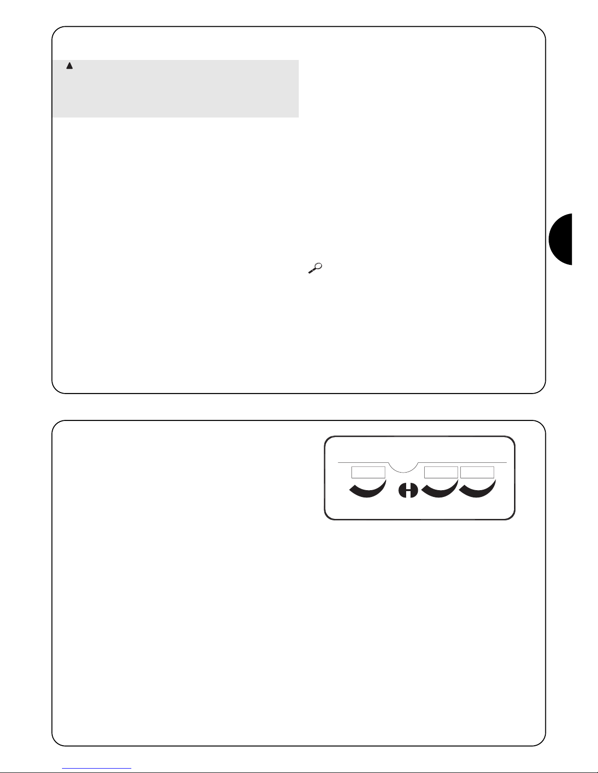
D
45
2.2.4) Überprüfung der Anschlüsse
Bei Durchführung der nachfolgenden Arbeiten werden Sie an
Kreisläufen arbeiten, die unter Spannung stehen; die meisten Teile der
Kreisläufe stehen unter Niedrigstspannung und sind daher ungefährlich;
einige Teile stehen unter Netzspannung, sie sind daher SEHR
GEFÄHRLICH! Gehen Sie daher sehr vorsichtig vor und NIE ALLEIN!
• Die Steuerung mit Spannung versorgen und sofort prüfen, ob
zwischen den Klemmen 5-6 ca. 24 Vac vorhanden ist.
• Prüfen, ob die OK-Led nach kurzfristigem Schnellblinken auf ein
regelmäßiges Blinken übergeht.
•
Nun prüfen, ob die Leds der Eingänge mit NC-Kontakten
eingeschaltet sind (alle Sicherheitsvorrichtungen aktiviert) und ob die
Leds der NA-Eingänge abgeschaltet sind (kein Befehl vorhanden);
im gegenteiligen Fall die Anschlüsse und Betriebstüchtigkeit der
verschiedenen Vorrichtungen kontrollieren. Der Eingang von “Stop”
spricht an, wenn sowohl FCA als auch FCC abgeschaltet sind.
• Überprüfen, ob die Endschalter richtig angeschlossen sind; den
Endschalterhebel bewegen und prüfen, ob der jeweilige
Endschalter anspricht, wobei sich die entsprechende Led an der
Steuerung ausschalten muss.
• Den Torflügel entriegeln und auf Hälfte Lauf bringen, dann
verriegeln, so dass sich der Torflügel sowohl in Öffnung als auch
in Schließung frei bewegen kann.
• Nun muss geprüft werden, ob die Bewegung in die korrekte
Richtung erfolgt, d.h. ob die von der Steuerung vorgesehene
Bewegung mit der tatsächlichen Bewegung der Torflügel
übereinstimmt. Diese Überprüfung ist sehr wichtig; wenn die
Richtung verkehrt ist, könnte der Automatismus in einigen Fällen
(zum Beispiel im “Halbautomatischen” Betrieb) anscheinend
ordnungsgemäß funktionieren, da in der Tat der Zyklus “AUF”
dem Zyklus “ZU” ähnlich ist, jedoch mit dem grundlegenden
Unterschied, dass die Sicherheitsvorrichtungen beim
Schließvorgang, der gewöhnlich der gefährlichste ist, ignoriert
werden und bei der Öffnung ansprechen und ein erneutes
Schließen verursachen werden, wobei das Hindernis mit
verheerenden Wirkungen getroffen wird!;
•
Um zu prüfen, ob der Drehsinn korrekt ist, genügt ein kurzer Impuls
auf den Eingang Schrittbetrieb; die erste, von der Steuerung
ausgeführte Bewegung nach ihrer Spannungsversorgung ist immer
AUF, es genügt daher, zu prüfen, ob sich der Automatismus in die
Öffnungsrichtung bewegt; falls die Bewegung dagegen in die
falsche Richtung erfolgt, muss:
die Spannungsversorgung abgeschaltet werden
der Stromverbinder des Motors um 180° gedreht und jener
der Endschalter (siehe “O” und “V” in Abb.1) umgekehrt werden.
Nachdem das Beschriebene ausgeführt worden ist, erneut
prüfen, ob der Drehsinn korrekt ist und gegebenenfalls den
letzten Punkt wiederholen.
Die “OK”-Led in der Mitte der Karte hat die Aufgabe, den Zustand der
internen Logik zu melden: ein regelmäßiges Blinken einmal pro Sekunde
bedeutet, dass der interne Mikroprozessor aktiv ist und auf Befehle wartet.
Wenn der Mikroprozessor dagegen eine Änderung des Zustandes eines
Eingangs wahrnimmt (sowohl Steuereingang als auch Dip-Switch der
Funktionen), wird ein schnelles Doppelblinken verursacht, auch wenn diese
Änderung keine sofortigen Wirkungen hat. Ein sehr schnelles, 3 S. langes
Blinken bedeutet, dass die Steuerung soeben mit Spannung versorgt worden
ist und einen Test der Innenteile ausführt; ein konstantes Blinken bedeutet,
dass der Test nicht erfolgreich war und dass daher ein Defekt vorliegt.
!
Die Einstellungen werden über Trimmer ausgeführt, die folgende
Parameter verändern:
Arbeitszeit (TL):
Die Arbeitszeit regelt die Höchstdauer der Bewegung in Öffnung
oder Schließung.
Für die Einstellung der Arbeitszeit TL, die Betriebsart
“Halbautomatisch” wählen und den Dip-Switch 1 auf On stellen, dann
den Trimmer TL auf etwa halben Weg regeln. Mit diesen Einstellungen
einen Zyklus in Öffnung und in Schließung ausführen und
gegebenenfalls den Trimmer TL so regulieren, dass während dieser
Zeit die ganze Bewegung ausgeführt werden kann und noch eine
Zeitspanne von 2 oder 3 Sekunden bleibt. Falls keine ausreichende
Zeit erzielt wird, auch wenn der Trimmer auf das Maximum gestellt
wird, kann die Überbrückung TLM auf der gedruckten Schaltplatte
zwischen den Trimmern TL und TP durchgeschnitten und dadurch
eine Arbeitsmehrzeit erhalten werden.
Pausezeit (TP):
Zur Einstellung im “automatischen” Betrieb der Zeit zwischen dem
Ende der Öffnungsbewegung und dem Anfang der Schließbewegung.
Für die Einstellung der Pausezeit TP, die Betriebsart “Automatisch”
wählen und den Dip-Switch 2 auf On stellen, dann den Trimmer TP
beliebig regeln. Für die Überprüfung muss eine Öffnungsbewegung
ausgeführt werden, dann die Zeit kontrollieren, die vor dem
automatischen Wiederschließen vergeht.
Kraft (F):
An der Steuerung vorhanden, dient diese Einstellung zur Regulierung
der Höchstkraft.
Besonders aufmerksam muss man bei der Einstellung des Trimmers
kraf (F) sein, da diese Einstellung den Sicherheitsgrad der
Automatisierung beeinflussen kann. Zur Einstellung mehrmalige
Versuche machen, dabei die vom Torflügel angewendete Kraft
messen und mit dem laut Vorschriften vorgesehenen Wert
vergleichen.
An den Steuerungen RO1010 und OT21 wird die Kraft über einen
mehrstelligen Wählschalter am Gehäuse des
Versorgungstransformators der Steuerung reguliert.
3) Einstellungen:
TP
TL
F
TLM

46
Nachdem die Überprüfungen und Einstellungen beendet sind, kann man auf die Prüfung der Anlage übergehen.
Die Automatisierung muss von erfahrenem Fachpersonal geprüft werden, das die vorzusehenden Tests je nach
vorhandenem Risiko festzulegen hat.
Die Prüfung ist das Wichtigste bei der Durchführung der ganzen Automatisierung. Jedes einzelne Teil wie Motor, Notstop, Photozellen usw.
kann eine spezielle Prüfung erfordern, daher wird empfohlen, sich an die Verfahren in den jeweiligen Anleitungen zu halten.
Für die Prüfung der Steuerung sind der Reihe nach folgende Schritte auszuführen:
1. Auswahl der Funktionen:
• Den Dip-Switch 1 auf ON stellen (halbautomatischer Betrieb)
• Sind die Anschlüsse in Abb.4 für die Verwendung von Photozellentest ausgeführt worden (falls die Karte PIU vorhanden ist), den
Dip-Switch 10 (Funktion Photozellentest) auf ON stellen.
• Alle anderen Dip-Switch auf OFF stellen.
2. Auf die Steuertaste “Öffnet” oder “Schrittbetrieb” drücken und prüfen, ob:
• sich die Blinkleuchte aktiviert
• eine Öffnungsbewegung beginnt
• die Bewegung anhält, wenn der Endschalter FCA in Öffnung erreicht wird.
3. Auf die Steuertaste “Schließt” oder “Schrittbetrieb” drücken und prüfen, ob:
• sich die Blinkleuchte aktiviert
• eine Schließbewegung beginnt
• die Bewegung anhält, wenn der Endschalter FCC in Schließung erreicht wird.
4. Eine Bewegung in Öffnung beginnen und prüfen, ob das Ansprechen einer Vorrichtung während der Bewegung:
• die am Eingang Stop angeschlossen, verursacht er das Anhalten mit kurzer Umkehrung der Bewegung
• die am Eingang Photo angeschlossen ist, keine Wirkung hat
•
die am Eingang Photo2 angeschlossen ist, das Anhalten und die Umkehrung der Bewegung verursacht (falls die Karte PIU vorhanden ist).
5. Eine Bewegung in Schließung beginnen und prüfen, ob das Ansprechen einer Vorrichtung während der Bewegung:
• die am Eingang Stop angeschlossen, verursacht er das Anhalten mit kurzer Umkehrung der Bewegung
• die am Eingang Photo angeschlossen ist, das Anhalten und die Umkehrung der Bewegung verursacht
• die am Eingang Photo2 angeschlossen ist, keine Wirkung hat (falls die Karte PIU vorhanden ist).
6. An den angeschlossenen Eingängen prüfen, ob die Aktivierung des Eingangs einen Schritt in der folgenden Sequenz verursacht:
• Eingang Schrittbetrieb: Sequenz = “Auf” – “Stop” – “Zu” – ”Stop”
• Eingang Öffnet: Sequenz = “Auf” – “Stop” – “Auf” – “Stop”
• Eingang Schließt: Sequenz = “Zu” – “Stop” - “Zu” – “Stop”
• Eingang Teil-Öffnung: Sequenz = “Teilweise Auf” – “Stop” – ”Zu” – “Stop” (falls die Karte PIU vorhanden ist).
7 Falls die Funktion Photozellentest benützt wird, die Effizienz des Test überprüfen (falls die Karte PIU vorhanden ist):
• Die Photozelle “Photo” abblenden, dann eine Bewegung beginnen und prüfen, dass diese nicht ausgeführt wird
• Die Photozelle “Photo2” abblenden, dann eine Bewegung beginnen und prüfen, dass diese nicht ausgeführt wird
• Den Kontakt der Photozelle “Photo” kurzschließen, dann eine Bewegung beginnen und prüfen, dass diese nicht ausgeführt wird
• Den Kontakt der Photozelle “Photo2” kurzschließen, dann eine Bewegung beginnen und prüfen, dass diese nicht ausgeführt wird
8. Die Tests für die Messung der Aufprallkraft durchführen, wie von der Vorschrift EN 12445 vorgesehen.
Werden am Ende der Prüfung weitere Funktionen aktiviert, welche die Sicherheit der Anlage reduzieren können, so sind diese Funktionen
besonders zu prüfen.
!
4) Prüfung

D
47
5) Betriebsarten
Beim manuellen Betrieb ermöglicht der Eingang “Öffnet” die
Öffnungsbewegung und der Eingang “Schließt” die Schließbewegung.
Der “Schrittbetrieb” ermöglicht die Bewegung abwechselnd in
Öffnung und Schließung.
Sobald die Eingangssteuerung beendet ist, hält die Bewegung an. In
Öffnung stoppt die Bewegung, wenn die Endschalter eingreifen, oder
die Zustimmung durch Photo2 fehlt (auf der Karte PIU); in Schließung
stoppt dagegen die Bewegung beim Fehlen der Zustimmung durch
Photo. Sowohl in Öffnung als auch in Schließung verursacht ein
Eingriff auf Stop immer ein sofortiges Anhalten der Bewegung.
Nachdem eine Bewegung gestoppt ist, muss die Eingangssteuerung
beendet werden, bevor mit einer erneuten Steuerung eine neue
Bewegung begonnen werden kann
Bei einer der automatischen Betriebsarten “(Halbautomatisch”,
“Automatisch” oder “Schließt immer”) verursacht ein Steuerimpuls auf
den Eingang “Öffnet” die Bewegung in Öffnung. Ein Impuls auf
“Schrittbetrieb” verursacht ein abwechselndes Öffnen oder Schließen.
Ein zweiter Impuls auf “schrittbetrieb” oder den gleichen Eingang, der
die Bewegung begonnen hat, verursacht ein “Stop”.
Der Eingriff auf “Stop” verursacht sowohl in Öffnung als auch in
Schließung das sofortige Anhalten der Bewegung.
Wird an einen Steuereingang statt eines Impulses ein Dauersignal
beibehalten, wird ein “Prioritätszustand“ verursacht, in dem die
anderen Steuereingänge deaktiviert bleiben (nützlich für den
Anschluss einer Uhr oder eines Tag-Nacht-Wählers).
Ist die automatische Betriebsweise gewählt, wird nach einer
Öffnungsbewegung eine Pause ausgeführt und danach eine
Schließung. Falls während der Pause ein Ansprechen von “Photo”
erfolgt, wird der Zeitgeber auf eine neue Pausezeit rückgestellt; sollte
dagegen während der Pausezeit ein Eingriff auf “Stop” erfolgen, wird
die Wiederschließfunktion gelöscht und man geht auf einen “Stop”Zustand über.
In Öffnung hat das Ansprechen von “Photo” keine Wirkung, wogegen
“Photo2” (auf der Karte PIU) die Umkehrung der Bewegung verursacht;
in Schließung verursacht das Ansprechen von “Photo” eine Umkehrung
der Bewegung, dann eine Pause, dann ein erneutes Schließen.
Die Steuerung verfügt über eine Reihe Mikroschalter, mit denen die
verschiedenen Funktionen aktiviert werden können, so dass die
Anlage dem Bedarf des Benutzers besser angepasst werden kann
und unter den verschiedenen Einsatzbedingungen sicherer ist. Die
Funktionen werden aktiviert, indem der entsprechende Dip-Switch
auf “On” gestellt wird, wogegen sie mit dem Dip-Switch auf “Off”
nicht eingeschaltet sind.
Einige der programmierbaren Funktionen sind an
Sicherheitsaspekte gebunden; daher die Wirkungen einer
Funktion sehr genau bewerten und überprüfen, welche
die größtmögliche Sicherheit gibt
!
Mit den Dip-Switches können die verschiedenen Betriebsarten eingestellt und die gewünschten Funktionen gemäß der folgenden Tabelle
eingeschaltet werden:
Switch 1-2: Off-Off = “Manuelle” Bewegung, bzw. Totmannbetrieb
On -Off = “Halbautomatische” Bewegung
Off-On = “Automatische” Bewegung, bzw. Automatische Schließung
On -On = “Automatische + Schließt Immer” Bewegung
Switch 3: On = Wohnblockbetrieb <nicht in der manuellen Betriebsart>
Switch 4: On = Vorwarnen
Switch 5: On =
Schließt 5 S. nach “Photo” < falls in “automatisch” > oder Schließt nach “Photo” < falls in “halbautomatisch” >
Switch 6: On = Sicherheit “Photo” auch in Öffnung
Switch 7: On = Allmählicher Start
Switch 8: On = Verlangsamung
Switch 9: On = Bremse
Switch 10: (an Robo) On = Kontrolllampe Tor Auf - Proportionalblinken
Ohne Karte PIU
(an Otto) On = Zeit zusätzliche Beleuchtung = 4 Minuten
Mit Karte PIU On = Funktion Photozellentest
ANMERKUNG: Einige Funktionen sind nur unter bestimmten Bedingungen möglich. Diese Funktionen befinden sich zwischen den Zeichen
“<...>”.
6) Programmierbare Funktionen
101

48
6.1) Beschreibung der Funktionen
Wir geben nun eine kurze Beschreibung der Funktionen, die eingeschaltet werden können, indem der entsprechende Dip-Switch auf “On”
gestellt wird.
Switch 1-2: Off-Off = “Manuelle” Bewegung, bzw. Totmannbetrieb
On-Off = “Halbautomatische” Bewegung
Off-On = “Automatische” Bewegung, bzw. Automatische Schließung
On-On = “Automatische + Schließt Immer” Bewegung
In der “manuellen” Betriebsart wird die Bewegung nur bis zum Vorhandensein der Steuerung (Taste gedrückt) ausgeführt.
In der “halbautomatischen” Betriebsart genügt ein Steuerimpuls, damit die gesamte Bewegung bis zum Ablauf der Arbeitszeit oder Erreichen
des Endschalters ausgeführt wird. In der “automatischen” Betriebsart folgt nach einer Öffnung eine Pause und dann ein automatisches
Schließen.
Die Funktion “Schließt immer” greift nach einem Stromausfall ein; falls das offene Tor wahrgenommen wird, wird automatisch ein
Schließvorgang gestartet, dem ein 5 Sekunden langes Vorwarnen vorausgeht
Switch 3: On = Wohnblockbetrieb (nicht in der manuellen Betriebsart)
Im Wohnblockbetrieb kann nach dem Start einer Öffnungsbewegung die Bewegung nicht mehr durch andere Steuerimpulse auf
Schrittbetrieb oder Öffnet bis zum Ende der Öffnungsbewegung unterbrochen werden.
In der Schließbewegung verursacht ein neuer Steuerimpuls das Anhalten und die Umkehrung der Öffnungsbewegung.
Switch 4: On = Vorwarnen
Bei Steuerimpuls wird zuerst das Blinklicht aktiviert und nach 5 S. (2 S. in manueller Betriebsart) beginnt die Bewegung.
Switch 5: On =
Schließt 5 S. nach “Photo” < falls in “automatisch” > oder Schließt nach “Photo” <falls in “halbautomatisch” >
Mit dieser Funktion, falls in der “Automatischen” Betriebsart, kann das Tor nur die für das Durchfahren notwendige Zeit geöffnet gehalten
werden; nach dem Ansprechen von “Photo” wird die Bewegung angehalten. 5 S. danach wird automatisch eine Bewegung in Schließung
beginnen. Falls in der halbautomatischen Betriebsart, aktiviert ein Ansprechen von “Photo” während der Schließbewegung das automatische
Schließen je nach eingestellter Pausezeit.
Switch 6: On = Sicherheit “Photo” auch in Öffnung
Gewöhnlich ist die Sicherheit “Photo” nur bei der Schließung aktiviert, wenn der Dip-Switch 6 auf “On” gestellt wird, verursacht die
Sicherheitsvorrichtung auch in Öffnung eine Unterbrechung der Bewegung.
In “halbautomatisch” oder “automatisch” erfolgt erneut eine Bewegung, wenn die Photozelle wieder frei ist.
Switch 7: On = Allmählicher Start
Der Beginn der Bewegung wird stufenweise ausgeführt, wodurch ruckartige Bewegungen der Automatisierung verhindert werden.
Switch 8: On = Verlangsamung
Die Verlangsamung ist eine Geschwindigkeitsreduzierung von 30% der Nenngeschwindigkeit, so dass ruckartige Bewegungen am Ende des
Vorgangs vermieden werden.
Neben der Reduzierung der Geschwindigkeit verringert die Verlangsamungsfunktion den Drehmoment des Motors um 70%.
Bei Automatisierungen, für die ein hoher Drehmoment erforderlich ist, könnte diese Reduzierung das sofortige Anhalten des Motors verursachen.
Version ROBO - THOR:
Am Ende der Bewegung in Öffnung oder Schließung, durch das
Ende der Arbeitszeit bedingt, es wird eine Verlangsamungsphase
ausgeführt, mit Dauer wie die der Arbeitszeit.
Wird die Bewegung durch das Ansprechen der Endschalter
beendet, so wird die Verlangsamung nicht ausgeführt; folglich muss
die Arbeitszeit so eingestellt werden, dass die Verlangsamung 30-50
cm vor dem Ansprechen der Endschalter beginnt.
Version OTTO:
Am Ende der Bewegung in Schließung dauert die Verlangsamung
3 s., falls durch das Ansprechen der Endschalter bedingt, so lange
wie der Arbeitszeit, falls durch das Ende der Arbeitszeit bedingt (für
ein korrektes Funktionieren der Verlangsamung wird der Gebrauch
der Endschalter empfohlen).
Bei der Bewegung in Öffnung wird keine Verlangsamung, sondern
ein stufenweises Anhalten ausgeführt.
Wird die Funktion Verlangsamung an empfindlichen
Installationen angewendet und dauert de Verlangsamung
länger als 3 s., so muss an den Klemmen der
Netzstromversorgung in der Nähe der Steuerung ein
!
Maschenfilter von mindestens 6A eingefügt werden,
mit einer Abschwächung von 30 dB, damit die laut
Norm EN 50081-1 vorgesehenen elektromagnetischen
Emissionsgrenzen nicht überschritten werden.

D
49
Switch 9: On = Bremse
Am Ende der Bewegung wird ein Bremsvorgang am Motor ausgeführt, anfänglich nur schwach, dann kräftiger, so dass das Tor schnell, aber
nicht ruckartig angehalten wird.
Mit dieser Funktion kann bei Beginn einer jeden Bewegung die Betriebstüchtigkeit der Photozellen kontrolliert werden. Siehe Abschnitt
PHOTOZELLENTEST.
Um eine Automatisierung mit 2 Torflügeln durchzuführen, die
entgegengesetzt arbeiten, ist wie folgt vorzugehen:
• Zwei Motoren verwenden – die Steuerungen müssen wie in
Abbildung 5 gezeigt angeschlossen sein.
• Die Blinkleuchte und die “Kontrolllampe Tor Auf“ unterschiedslos
an eine der zwei Steuerungen.
• Die Eingänge müssen untereinander parallel geschaltet sein.
• Der “Gemeine Leiter” der Eingänge kann an eine der 2
Steuerungen angeschlossen werden.
• Die 0Volt (Klemme 5) der beiden Steuerungen zusammen
anschließen.
• Die Funktion Photozellentest darf nicht verwendet werden.
• Die Funktion “Wohnblockbetrieb” (Dip-Switch 3) sollte aktiviert
werden, damit die Torflügel wieder synchronisiert werden, falls
die 2 Steuerungen nicht mehr gleichlaufen.
7) Verwendung von zwei Steuerungen an entgegengesetzten Torflügeln
Switch 10: On
ROBO e THOR
Ohne Karte PIU:
• Kontrolllampe Tor Auf mit Proportionalblinken
Mit Karte PIU:
• “Photozellentest”
OTTO
Ohne Karte PIU:
• Zeit zusätzliche Beleuchtung = 4 Minuten
Mit Karte PIU:
• “Photozellentest”
5

50
Karte PIU
Die Steuerung enthält bereits alle Funktionen, die in einer normalen Installation verwendet werden; um den Erforderungen besonderer
Anlagen gerecht zu werden, wurde die Sonderkarte “PIU” vorbereitet, mit der neue Funktionen wie Ampel, zusätzliche Beleuchtung, Elektroschloss, Photo2, Teilöffnung und Photozellentest hinzugefügt werden können.
Rot = rotes Licht der Ampel
Gewöhnlich immer abgeschaltet, schaltet sich
das rote Licht während der Torbewegung ein.
Grün = grünes Licht der Ampel
Gewöhnlich eingeschaltet, schaltet sich das
grüne Licht während der Torbewegung ab.
Elektroschloss = Ausgang für Elektroschloss.
Das Elektroschloss wird am Anfang der
Bewegung in Öffnung für 1,5 Sekunden aktiviert.
Zusätzliche
Beleuchtung/
Photozellentest = Wenn dieser Ausgang für die zusätzliche
Beleuchtung benutzt wird, wird sich am Beginn
jeder Bewegung eine zusätzliche Beleuchtung
einschalten, die bis nach Ende der Bewegung
und je nach Zeit, die am Trimmer T.Cor. auf der
Karte “PIU” programmiert wird, eingeschaltet
bleibt. Wenn man die Funktion Photozellentest
aktiviert (Dip-Switch10=ON), so wird es dieser
Ausgang ermöglichen, einen Test der
Photozellen bei Bewegungsbeginn auszuführen.
Teil-Öffnung = Eingang für Teilöffnung (Teilw. Auf, Stop, Zu,
Stop). Führt die gleiche Funktion wie
Schrittbetrieb an der Hauptkarte aus, mit dem
Unterschied, dass die Bewegung in Öffnung die
am Trimmer T.AP.P. der Karte “PIU” eingestellte
Zeit dauert.
Foto 2 = Eingang 2. Sicherheitsvorrichtung. Diese
Sicherheitsvorrichtung spricht nur bei der
Bewegung in Öffnung an und verursacht ein
Stop der Bewegungen mit eventuellem
Wiederschließen, falls die “Halbautomatische”
oder die “Automatische” Betriebsart an der
Steuerung programmiert ist.
24 V = 24V Ausgang, für die Versorgung von
Nebenvorrichtungen wie Photozellen oder
anderes verwendbar. Die Klemme 11 ist auch
der Gemeine Leiter der Eingänge.
Karte RADIO
An der Steuerung befindet sich ein Verbinder für das Einstecken einer von Nice hergestellten Radiokarte, über die der Eingang SCHRTTBETRIEB betätigt werden kann, wodurch die Steuerung über einen Sender ferngesteuert wird.
8) Sonderzubehör
Die Steuerung, ein elektronischer Teil, ist praktisch wartungsfrei;
trotzdem sollte die Effizienz und die Einstellung der Regelvorrichtung
der Motorkraft regelmäßig (mindestens alle 6 Monate) überprüft
werden, wobei gegebenenfalls die Einstell-Trimmer zu betätigen
sind.
Die in Prüfung verzeichneten Schritte nochmals durchführen, um die
Effizienz der Endschalter und der Sicherheitsvorrichtungen
(Photozellen, Sicherheitsleisten, usw.) und den korrekten Betrieb der
Blinkleuchte zu kontrollieren.
9) Wartung
Dieses Produkt besteht aus verschiedenen Werkstoffen, von denen
einige wiederverwertet werden können.
Informieren Sie sich über die Recycling- oder Entsorgungsmethoden
und halten Sie sich strikt an die örtlich gültigen Bestimmungen.
Bestimmte elektronische Komponenten könnten
umweltverschmutzende Substanzen enthalten – nicht in
die Umwelt geben!
!
10) Entsorgung

D
51
Diese Punkte sollen dem Installateur bei der Lösung einiger der
häufigsten Probleme, die bei der Installation auftreten können,
behilflich sein.
Keine Led eingeschaltet:
• Prüfen, ob die Steuerung mit Netzspannung versorgt ist (prüfen,
ob an den Klemmen 1-2 die Netzspannung und an den Klemmen
5-6 eine Spannung von ca. 24Vac vorhanden ist)
• Prüfen, ob die 2 Sicherungen der Versorgung beschädigt sind;
falls auch jetzt keine Led eingeschaltet ist, so ist der Defekt
wahrscheinlich schwer und die Steuerung muss daher
ausgetauscht werden.
Die OK-Led blinkt regelmäßig, aber die Leds der EINGÄNGE
melden den Zustand der jeweiligen Eingänge nicht
• Die Anschlüsse an den Klemmen der Eingänge 7÷13 genau
überprüfen.
Keine Bewegung
• Prüfen, ob die Leds der Sicherheitsvorrichtungen “Stop” (FCA +
FCC), “Photo” und eventuell “Photo2” aktiviert sind und ob die
LED der Betriebsart (“Schrittbetrieb”, “Öffnet” oder “Schließt”)
während der Dauer des Befehls aufleuchtet.
Während der Bewegung führt das Tor eine Umkehrung aus
Die Ursachen einer Umkehrung sind:
• Ein Ansprechen der Photozellen (“Photo2” in Öffnung, “Photo” in
Schließung); in diesem Fall die Anschlüsse der Photozellen
kontrollieren und gegebenenfalls die Anzeige-LEDS der Eingänge
überprüfen.
11) Was tun, wenn ….
Stromversorgung : 230 Vac 50/60 Hz
Versionen/V1 : 120 Vac 50/60 Hz
Höchststrom Nebeneinrichtungen 24 V : 200mA
Ausgang Blinkleuchte : Für Blinkleuchten mit Netzspannung ist die Höchstleistung 40 W
Ausgang Kontrolllampe Tor Auf “SCA” : Für 24Vac Kontrolllampen ist die Höchstleistung 2 W
Betriebstemperatur : -20 ÷ 70 °C
Arbeitszeit an ROBO/THOR : von 2.5 bis >60 s. oder von <50 bis >120 s. mit TLM verstellbar
Arbeitszeit an OTTO : von 2.5 bis >20 s. oder von <20 bis >40 s. mit TLM verstellbar
Pausezeit : von 5 bis >160 s. verstellbar.
An Karte PIU
Zeit Teilöffnung ROBO/THOR : von 1 bis > 30 s. verstellbar.
Zeit Teilöffnung OTTO : von 1 bis > 14 s. verstellbar.
Zeit Zusätzliche Beleuchtung : von 1 bis > 180 s. verstellbar.
12) Technische Merkmale

52
central de mando
motorreductores
robo, thor, otto
Advertencias:
Este manual está destinado sólo al personal técnico
cualificado para la instalación.
Ninguna información contenida en este manual puede ser
considerada de interés para el usuario final.
Este manual se refiere sólo a esta central y no se debe
emplear para otros productos.
Se aconseja leer con atención, una vez como mínimo, todas las
instrucciones antes de proceder con la instalación.
!
Indice: pág.
1 Descripción del producto 53
2 Instalación 54
2.1 Instalación típica 54
2.2 Conexiones eléctricas 54
2.2.1 Esquema eléctrico 55
2.2.2 Descripción de las conexiones 55
2.2.3 Fototest 56
2.2.4 Control de las conexiones 57
3 Regulaciones 57
4 Ensayo 58
5 Modos de funcionamiento 59
pág.
6 Funciones programables 59
6.1 Descripción de las funciones 60
7 Empleo de dos centrales en hojas 61
contrapuestas
8 Accesorios opcionales 62
9 Mantenimiento 62
10 Desguace 62
11 Qué hay que hacer si… 63
12 Características técnicas 63

E
53
1) Descripción del producto
Esta central para la automatización de cancelas o puertas
automáticas permite accionar los actuadores ROBO, OTTO, THOR
de corriente alterna monofásica.
De acuerdo con el tipo de actuador que se ha de accionar, la central
tiene variantes, tales como: “Regulación de Fuerza”, “Indicador
luminoso Cancela Abierta” y “Luz de cortesía”.
Además, cuenta con una serie de funciones que se seleccionan por
medio de los “Dip-Switches” (mini-selectores) y regulaciones que se
realizan con los trimmers.
En la central hay leds situados cerca de las entradas que indican el
estado; otro led, colocado cerca del microprocesador, indica que la
lógica interior funciona correctamente.
Para reconocer más fácil las piezas en la fig.1 se muestran los
componentes más importantes.
LMNOP
J
QRST
VU
I
X
W
Y
H
G
FZ
EDCBA
CH
P. P.
AP
FOTO
FCA
FCC
OK
Dip-Switch de selección de las funciones
Trimmer de regulación Fuerza
Trimmer de regulación Tiempo Funcionamiento TL
Trimmer de regulación Tiempo Pausa TP
Caja de conexiones para la antena y 2° canal
Conexión tarjeta RADIO
Led de indicación del estado de las entradas
Caja de conexiones Entradas / Salidas de mando
Relé Común
Caja de conexiones alimentación / Luz intermitente
Conector primario del transformador
Fusible de línea (5A)
Conector de salida de la Luz de Cortesía (sólo en OTTO)
Salida alimentación motor
Conector del condensador
Relé “Punto de arranque”
Triac “Luz de cortesía” (sólo en OTTO)
Triac “Cerrar”
Triac “Abrir”
Conector secundario del transformador
Entrada fin de carrera FCA / FCC
Fusible de baja tensión (500mA)
Conexión tarjeta PIU
Led OK
Microprocesador
A
B
C
D
E
F
G
H
I
J
L
M
N
O
P
Q
R
S
T
U
V
W
X
Y
Z
1
Código Producto* Código Central de mando* Función Adicional
ROBO
RO1000
RO1020
ROA3 Trimmer de “Regulación Fuerza”
RO1010 ROA4 Relé “Punto de arranque”
THOR
TH1551 THA5 Trimmer de “Regulación Fuerza”
TH2251 THA6 Relé “Punto de arranque”
OTTO OT21 OTA1 Salida “Luz de cortesía”
* = añadir al código V1 para versión 120 V 50/60 Hz

54
2.1) Instalación típica
A fin de aclarar algunos términos y algunos aspectos de una instalación de automatización para puertas o cancelas, damos un ejemplo típico.
ROBO / THOR OTTO
1) Par de fotocélulas “Fotocélula”
2) Luz intermitente
3) Selector de llave
4) Borde neumático
5) Par de fotocélulas “Fotocélula 2”
Recordamos en particular que:
• Todas las fotocélulas fabricadas por NICE disponen del sistema de Sincronismo, que permite eliminar el problema de la interferencia
entre dos pares de fotocélulas (para mayores aclaraciones véanse las instrucciones de las fotocélulas).
• El par de fotocélulas “Fotocélula” en apertura no tiene efecto, mientras que provoca una inversión durante el cierre.
• El par de fotocélulas “Fotocélula 2” durante el cierre no tiene efecto mientras que provoca una inversión durante la apertura.
Recuerde que los sistemas de cancelas y puertas
automáticas tienen que ser instalados sólo por personal
técnico cualificado y respetando las normas vigentes.
Siga con atención las advertencias del fascículo:
“Advertencias para el instalador”.
!
2) Instalación
2a
2b
2.2) Conexiones eléctricas
Para garantizar la seguridad del instalador y no averiar
los componentes, mientras se efectúan las conexiones
eléctricas, o se conectan las distintas tarjetas, la central
debe estar completamente apagada.
• Alimente la central con un cable de 5 x 1,5mm
2
; si la distancia
entre la central y la conexión a la instalación de tierra es superior
a 30 m, hay que instalar una placa de conexión a tierra cerca de
la central.
• En las conexiones de las piezas de baja tensión de seguridad
use cables de sección mínima de 0,25mm
2
.
• Use cables de conductores encerrados si la longitud es superior
a 30m, conectando la trenza de masa sólo del lado de la central.
• No conecte los cables en cajas enterradas aún si son
herméticas.
• Las entradas de los contactos tipo Normalmente Cerrado (NC)
que no se utilicen se tienen que conectar al "Común 24V " por
medio de un conector puente, excluidas las entradas de las
fotocélulas si la función fototest está conectada; para más
aclaraciones véase el párrafo “Fototest”.
• Si para la misma entrada hay varios contactos NC, se deben
conectar en “Serie” entre sí.
• Si las entradas de los contactos tipo Normalmente Abierto (NA)
no se utilizan, se tiene que dejar libres.
• Si para la misma entrada hay varios contactos NA se conectan
en “Parallelo” entre sí.
• Los contactos tienen que ser exclusivamente mecánicos y sin
ningún potencial; no se admiten conexiones de configuración
como aquéllas definidas “PNP”, “NPN”, “Open Collector”, etc.
!

E
55
2.2.1) Esquema eléctrico
2.2.2) Descripción de las conexiones
Damos una descripción breve de las posibles conexiones de la central hacia el exterior.
Bornes Funciones Descripción
1-2 : Alimentación = Línea de alimentación de red
3-4 : Luz intermitente = Salida para la conexión de la luz intermitente con tensión de red (máx. 40W)
5-6 : 24 Vca = Alimentación de los equipos auxiliares 24 Vca (Fotocélula, Radio, etc.) Máx 200mA
7 : Común = Común para todas las entradas
8:
Indicador luminoso C.A
= Indicador luminoso cancela abierta 24 Vca máx. 2W (no instalado en la versión OTTO)
9 : Stop = Entrada con función de parada de la maniobra e inversión breve del movimiento
10 : Fotocélula = Entrada para los dispositivos de seguridad (Fotocélulas, bordes neumáticos)
11 : Paso a Paso (PP) = Entrada para el funcionamiento cíclico ("Abrir" - "Stop" - "Cerrar" - "Stop")
12 : Abrir = Entrada para el movimiento de apertura
13 : Cerrar = Entrada para el movimiento de cierre
41-42 : 2° Canal Radio = Salida del posible segundo canal del radiorreceptor
43-44 : Antena = Entrada para la antena del radiorreceptor
3

56
2.2.3) Fototest
“Fototest” es una óptima solución en términos de fiabilidad para los
dispositivos de seguridad, permite lograr la “categoría 2” según la norma
UNI EN 954-1 (edic. 12/1998) respecto del grupo central y fotocélulas
de seguridad.
Cada vez que se acciona una maniobra, son controlados todos los
dispositivos de seguridad implicados y la maniobra comienza sólo si
todo está en perfectas condiciones. Si en cambio la prueba no da
resultado positivo (fotocélula encandilada por el sol, cables en
cortocircuito, etc.) se detecta la avería y la maniobra no se realiza.
Para obtener la función
“Fototest” es necesario
:
• Utilizar la tarjeta adicional “PIU”.
• Configurar el Dip-Switch 10 en ON .
• Realizar una configuración especial en las conexiones de los
dispositivos de seguridad, como muestra la fig. 4a, que prevé
la conexión de la alimentación de los transmisores de las
fotocélulas no directamente a la salida de los equipos auxiliares,
sino que cortando dicha alimentación pasando por los bornes 7
y 8 de la tarjeta PIU. La corriente máxima que se utiliza en el
salida “Fototest” de la tarjeta “PIU” es 100mA (2 pares de
fotocélulas Nice).
• Alimentar los receptores directamente desde la salida de los
equipos auxiliares de la central (bornes 5-6).
Si en un segundo momento no se desea utilizar más la función
“Fototest”, habrá que bajar el Dip-Switch 10 y modificar la configuración de
las conexiones, como muestra la fig. 4b.
El ensayo de las fotocélulas se realiza del siguiente modo: cuando
se requiere un movimiento, en primer lugar se controla que todos los
receptores implicados en el movimiento den el asenso; luego, se
apaga la alimentación a los transmisores y se controla que todos los
receptores señalen el hecho cortando el asenso; por último, se
reactiva la alimentación de los transmisores y se controla
nuevamente el asenso por parte de todos los receptores. Sólo si
esta secuencia da resultado positivo, la maniobra iniciará.
Además, se aconseja activar el sincronismo cortando las conexiones
puente en los transmisores; este es el único modo para garantizar
que dos pares de fotocélulas no interfieran entre sí. Controle en el
manual de las fotocélulas las instrucciones para el funcionamiento
"Sincronizado".
Si una entrada sujeta a “Fototest” no se utilizara (ejemplo
“Fotocélula2”) e igualmente desea la función fototest, hay que
conectar con un conector puente la entrada no utilizada, como
indicado en la fig. 4c.
“Fotocélula” y “Fotocélula2” con “Fototest”
“Fotocélula” y “Fotocélula2” sin “Fototest”
“Fotocélula” con “Fototest”
4a
4b
4c

E
57
2.2.4) Control de las conexiones
Las siguientes operaciones se efectúan con los circuitos bajo
tensión; la mayoría de los circuitos está a muy baja tensión de
seguridad y, por ello, no son peligrosos; algunas piezas están bajo
tensión de red, es decir, “MUY PELIGROSAS”! Tenga mucho
cuidado en lo que está haciendo y NUNCA TRABAJE SÓLO!
• Alimente la central y controle de inmediato que entre los bornes
5-6 haya una tensión de 24 Vca.
• Controle que, después de un parpadeo rápido, el led “OK”
parpadee con una cadencia regular.
•
Entonces, controle que los leds que corresponden a las entradas
con contactos tipo NC estén encendidos (todos los dispositivos
de seguridad accionados) y que los leds que corresponden a las
entradas con contactos tipo NA estén apagados (ningún
accionamiento activo); si esto no se produce, controle las
conexiones y que todos los dispositivos funcionen correctamente.
la entrada STOP se acciona apagando FCA y FCC.
• Controle que los fines de carrera estén bien conectados; mueva
la palanca del fin de carrera y controle que el fin de carrera
correspondiente se accione, apagando el led respectivo en la
central.
• Desbloquee la hoja y colóquela a la mitad de la carrera, luego
bloquéela para que se pueda abrir o cerrar libremente.
• Entonces, controle si el movimiento se efectúa en la dirección
correcta, es decir, controle que el movimiento previsto por la
central y aquél efectivo de las hojas correspondan. Este control
es fundamental; si la dirección es incorrecta, en algunos casos
(por ejemplo en modo “semiautomático”) la automatización
aparentemente podría funcionar regularmente; en efecto, el ciclo
“Abrir” es parecido al ciclo “Cerrar” con la diferencia fundamental
de que los dispositivos de seguridad son ignorados en la
maniobra de cierre, la cual es generalmente más peligrosa, y se
accionarán durante la apertura provocando un cierre sobre el
obstáculo con resultados desastrosos.
• Para controlar si el sentido de rotación es correcto, es suficiente
dar un breve impulso en la entrada Paso a Paso (PP); la primera
maniobra que la central efectúa tras haber sido accionada
siempre es Abrir, luego es suficiente controlar si la
automatización se abre; por último, si el movimiento se ha
efectuado en el sentido incorrecto es necesario:
Apagar la alimentación
Girar 180° el conector de alimentación del motor y el de
los fines de carrera (Ref. “O” y Ref. “V” de Fig.1)
Una vez efectuado cuanto descrito, conviene probar
nuevamente si el sentido de rotación es correcto, repitiendo el
último punto.
El led “OK”, situado en el centro de la tarjeta, tiene la función de
señalar el estado de la lógica interior: un parpadeo regular cada 1 segundo
indica que el microprocesador interior está activo y espera el mando. En
cambio, cuando el microprocesador reconoce una variación del estado de
una entrada (bien de una entrada de mando o de un Dip-Switch de las
funciones) produce un parpadeo doble rápido, incluso si la variación no
provoca efectos inmediatos. Un parpadeo rápido de 3 s. indica que la central
se ha apenas encendido y está realizando un ensayo de las piezas internas;
por último un parpadeo inconstante indica que el ensayo no tuvo resultados
positivos y, por consiguiente, hay una avería.
!
Las regulaciones se efectúan con los trimmers que actúan
modificando los siguientes parámetros:
Tiempo Funcionamiento (TL):
Regula la duración máxima de la maniobra de apertura o cierre.
Para regular el tiempo de funcionamiento TL, seleccione el modo de
funcionamiento “Semiautomático” desplazando hacia ON el DipSwitch 1 y luego regule el trimmer TL a la mitad de la carrera. Con
dichas regulaciones realice un ciclo de apertura y de cierre; si fuera
necesario, actúe sobre la regulación del trimmer TL de manera que
sea suficiente para cumplir toda la maniobra y que todavía quede un
margen de 2 ó 3 s..
Si colocando el trimmer TL al máximo no se obtiene un tiempo
suficiente, corte el conector puente TLM, colocado en el circuito
impreso entre los trimmers TL y TP, para obtener un tiempo de
Funcionamiento mayor.
Tiempo Pausa (TP):
En el funcionamiento “automático” regula el tiempo entre el final de
la maniobra de apertura y el comienzo de la maniobra de cierre.
Para regular el Tiempo Pausa TP, seleccione el modo de
funcionamiento “Automático” desplazando hacia ON el Dip-Switch 2,
luego regule el trimmer TP a placer. Para el control, ejecute una
maniobra de apertura y controle el tiempo que transcurre antes del
cierre “Automático”.
Fuerza (F):
Instalada en la central para el accionamiento, permite regular el valor
de la “Fuerza” máxima.
Preste mucha atención cuando regule el trimmer “Fuerza” (F),
puesto que puede influir sobre el grado de seguridad de la
automatización. Para la regulación hay que actuar por tentativas
sucesivas, midiendo la fuerza aplicada a la hoja y comparándola con
cuanto previsto por las normas.
En las centrales RO1010 y OT21 la “Fuerza” se regula con un selector
de varias posiciones, situado en la caja del transformador de
alimentación de la central.
3) Regulaciones
TP
TL
F
TLM

58
Finalizados los controles y regulaciones es posible efectuar el ensayo de la instalación.
El ensayo de la automatización tiene que ser efectuado por personal cualificado y experto que deberá establecer los
ensayos previstos de acuerdo con el riesgo presente.
El ensayo es la parte más importante de toda la etapa de realización de la automatización. Cada componente, por ejemplo motor, dispositivo
de parada de emergencia, fotocélulas, etc. puede requerir un ensayo específico; por consiguiente, se aconseja seguir los procedimientos
indicados en los manuales de instrucciones respectivos.
Para el ensayo de la central ejecute el siguiente procedimiento:
1. Seleccione las funciones:
• Configure en ON el Dip-Switch 1 (Funcionamiento “semiautomático”)
• Si no se han realizado las conexiones de la fig.4a para el uso de la función “Fototest” (si está instalada la tarjeta PIU), configure en
ON el Dip-Switch 10 (Función “fototest”).
• Configure en OFF todos los demás Dip-Switches
2. Oprima el botón de mando “Abrir” o “Paso a Paso” y compruebe que:
• se active la luz intermitente
• empiece una maniobra de apertura
• el movimiento se detenga al alcanzar el fin de carrera de apertura FCA.
3. Oprima el botón de mando “Cerrar” o “Paso a Paso” y compruebe que:
• se active la luz intermitente
• empiece una maniobra de cierre
• el movimiento se detenga al alcanzar el fin de carrera de cierre FCC
4. Haga iniciar una maniobra de apertura y controle que durante la maniobra, el accionamiento de un dispositivo:
• conectado a la entrada “Stop”, provoca la parada con una inversión breve del movimiento
• conectado a la entrada “Fotocélula”, no tenga ningún efecto
• conectado a la entrada “Fotocélula2”, provoque la parada y la inversión de la maniobra (si está instalada la tarjeta PIU).
5. Haga iniciar una maniobra de cierre y controle que durante la maniobra, el accionamiento de un dispositivo:
• conectado a la entrada “Stop”, provoca la parada con una inversión breve del movimiento
• conectado a la entrada “Fotocélula”, provoque la parada y la inversión de la maniobra
• conectado a la entrada “Fotocélula2”, no tenga ningún efecto (si está instalada la tarjeta PIU).
6. En las entradas conectadas, controle que la activación de la entrada provoque un paso en la secuencia:
• Entrada Paso a Paso: Secuencia = “Abrir” – “Stop” – “Cerrar” – “Stop”
• Entrada Abrir: Secuencia = “Abrir” – “Stop” – “Abrir” – “Stop”
• Entrada Cerrar: Secuencia = “Cerrar” – “Stop” - “Cerrar” – “Stop”
• Entrada Abrir Parcial: Secuencia = “Abrir Parcial” – “Stop” – “Cerrar” – Stop” (si está instalada la tarjeta PIU).
7 Si se utiliza la función fototest, controle la eficiencia del ensayo (si está instalada la tarjeta PIU):
• Cubra la fotocélula "Fotocélula", haga iniciar una maniobra y controle que dicha maniobra no arranque
• Cubra la fotocélula "Fotocélula2", haga iniciar una maniobra y controle que dicha maniobra no arranque
•
Realice un cortocircuito en el contacto de la fotocélula "Fotocélula", haga iniciar una maniobra y controle que dicha maniobra no arranque
•
Realice un cortocircuito en el contacto de la fotocélula "Fotocélula2", haga iniciar una maniobra y controle que dicha maniobra no arranque
8. Realice los ensayos para medir las “Fuerzas de Impacto”, como previsto por la norma EN 12445.
Si al final del ensayo se activan otras funciones que puedan reducir la seguridad de la instalación, es necesario efectuar el ensayo específico
de dichas funciones.
!
4) Ensayo

E
59
5) Modos de funcionamiento
En el funcionamiento en modo manual la entrada “Abrir” permite el
movimiento de apertura y la entrada “Cerrar” permite el movimiento
de cierre. El “Paso a Paso” permite el movimiento de apertura y
cierre alternativamente.
Ni bien cesa el mando de entrada el movimiento se detiene. Durante
la apertura el movimiento se detiene cuando se accionan los fines de
carrera, o bien si falta el permiso de la “Fotocélula 2” (en la tarjeta
PIU); en cambio, durante el cierre, el movimiento se detiene si falta
el asenso de “Fotocélula”. El accionamiento de “Stop” provoca una
parada inmediata del movimiento tanto durante la apertura como
durante el cierre. Cuando el movimiento se detiene, deje de accionar
el mando en entrada antes de poder iniciar con un nuevo
movimiento.
Durante el funcionamiento en uno de los dos modos automáticos
(“Semiautomático”, “Automático” o “Cerrar Siempre”) un impulso de
accionamiento en la entrada “Abrir” provoca el movimiento de
apertura. Un impulso sobre “Paso a Paso” provoca la apertura o el
cierre alternativamente. Un segundo impulso sobre “Paso a Paso”,
o sobre la misma entrada que ha comenzado el movimiento,
provoca un Stop.
El accionamiento de “Stop” provoca una parada inmediata del
movimiento, tanto durante la apertura como durante el cierre.
Si en una entrada de mando en vez de un impulso se mantiene una
señal continua, se provoca un estado de “preponderancia” en el cual
las demás entradas quedan desactivadas (útil para conectar un
reloj o un selector Noche-Día).
Si se selecciona el modo de funcionamiento automático, tras una
maniobra de apertura, se efectúa una pausa y luego el cierre. Si
durante la pausa se acciona “Fotocélula” el temporizador se
restablecerá con un nuevo tiempo de pausa; si en cambio durante
la pausa se acciona “Stop”, la función de cierre se pone a cero y se
pasa a un estado de “ Stop”. Durante la apertura el accionamiento
de “Fotocélula” no tiene ningún efecto, mientras que la “Fotocélula2”
(en la tarjeta PIU) provoca la inversión del movimiento; durante el
cierre, el accionamiento de “Fotocélula” provoca una inversión del
movimiento, luego una pausa y finalmente un nuevo cierre.
La central dispone de una serie de microinterruptores que permiten
activar varias funciones para que la instalación sea más adecuada a
las exigencias del usuario y más segura en cualquier condición de
empleo. Todas las funciones se activan poniendo el respectivo DipSwitch en la posición “On”, mientras que con el Dip-Switch
correspondiente en “Off” no están activas.
Algunas de las funciones programables están
vinculadas con aspectos de la seguridad; evalúe con
mucha atención los efectos de una función y verifique
cuál es la función que brinde la mayor seguridad posible.
!
Los Dip-Switches permiten seleccionar los diferentes modos de funcionamiento e introducir las funciones deseadas según la siguiente tabla:
Switch 1-2: Off-Off = Movimiento “Manual”, es decir Pulsador de interrupción automática
On -Off = Movimiento “Semiautomático”
Off-On = Movimiento “Automático”, es decir cierre automático
On -On = Movimiento “Automático + Cerrar Siempre”
Switch 3: On = Funcionamiento Comunitario < no disponible en modo manual >
Switch 4: On = Parpadeo previo
Switch 5: On = Cierra 5 s. después de Fotocélula < si está en “Automático”> o Cierra después de “Fotocélula”
< si está en “Semiautomático”>
Switch 6: On = Dispositivo de seguridad “Fotocélula” también durante apertura
Switch 7: On = Arranque gradual
Switch 8: On = Deceleración
Switch 9: On = Freno
Switch 10: (en Robo) On = Indicador luminoso C.A. con parpadeo proporcional
Sin tarjeta PIU
(en Otto) On = Tiempo luz de cortesía = 4 minutos
Con tarjeta PIU On = Función “Fototest”
NOTA: algunas funciones son posibles en determinadas condiciones que se señalan con las notas entre los signos “<...>”.
6) Funciones programables
101

60
6.1) Descripción de las funciones
A continuación, damos una breve descripción de las funciones que se pueden introducir colocando en “On” el Dip-Switch correspondiente.
Switch 1-2: Off-Off = Movimiento “Manual” (Pulsador de interrupción automática)
On-Off = Movimiento “Semiautomático”
Off-On = Movimiento “Automático” (cierre automático)
On-On = Movimiento “Automático + Cerrar siempre”
Durante el funcionamiento “Manual” el movimiento se efectúa sólo hasta que se acciona el mando (botón apretado).
En modo “Semiautomático” es suficiente dar un impulso de mando para que se cumpla todo el movimiento, hasta que termina el Tiempo
Funcionamiento o alcanzar el fin de carrera. En el funcionamiento en modo “Automático”, después de la apertura, se efectúa una pausa y
luego un cierre automático. La función “Cerrar Siempre” se acciona tras un corte de alimentación, si detecta que la cancela está abierta, se
pone en marcha automáticamente una maniobra de cierre, antecedida por 5 segundos de parpadeo previo.
Switch 3: On = Funcionamiento comunitario (no disponible en modo Manual)
Durante el funcionamiento comunitario, una vez que se puso en marcha un movimiento de apertura, la maniobra no puede ser interrumpida
por otros impulsos de mando en “Paso a Paso” o “Abrir”, hasta que no finalice el movimiento de apertura. Durante el movimiento de cierre,
al efectuar un nuevo accionamiento, se produce la parada y la inversión del movimiento y se abre nuevamente.
Switch 4: On = Parpadeo previo
Al recibir el impulso de mando, primero se activa la luz intermitente, luego, transcurridos 5 s. (2 s. si está en modo “manual”) inicia el
movimiento.
Switch 5: On = Cierra 5 s.s después de “Fotocélula” < si está en “Automático” > o Cierra después de “Fotocélula”
< si está en “Semiautomático” >
Esta función, si está en ciclo automático, permite mantener la cancela abierta sólo por el tiempo necesario para el paso; en efecto, después
de la activación de Fotocélula la maniobra se detiene. Después de 5 s., arrancará automáticamente una maniobra de cierre. Si está en ciclo
semiautomático, un accionamiento de fotocélula en la maniobra de cierre activa el cierre automático con el tiempo de pausa regulado.
Switch 6: On = Dispositivo de seguridad (“Fotocélula”) también durante apertura
Normalmente, el dispositivo de seguridad “Fotocélula” está activo sólo durante la maniobra de cierre, si el Dip-Switch 6 se coloca en "On"
el accionamiento del dispositivo de seguridad provoca una interrupción del movimiento también durante la apertura.
Si está en “Semiautomático” o “Automático”, el movimiento de apertura se reanudará inmediatamente después de la desconexión.
Switch 7: On = Arranque gradual
Ejecuta el arranque gradual del movimiento evitando sacudidas indeseables de la automatización.
Switch 8: On = Deceleración
La deceleración consiste en una disminución de la velocidad del 30% de la velocidad nominal, para evitar sacudidas inútiles al final de la
maniobra.
La función de deceleración, además de disminuir la velocidad de la automatización, disminuye un 70% el par del motor.
En automatizaciones que requieren un par elevado, dicha disminución podría provocar la parada inmediata del motor.
Versión ROBO / THOR:
Al terminar la maniobra de apertura o cierre, por la conclusión del
Tiempo Funcionamiento, se efectúa una deceleración que dura
tanto cuanto el Tiempo de Trabajo.
Si la maniobra concluye porque se accionó el fin de carrera, la
deceleración no se ejecuta, entonces hay que regular el Tiempo
Funcionamiento para que comience a decelerar 30-50 cm antes del
accionamiento de los fines de carrera.
Versión OTTO:
Al terminar la maniobra de cierre, la etapa de deceleración dura 3 s.,
si es activada por el accionamiento de los fines de carrera; cuanto el
TL si es activada por el final del Tiempo Funcionamiento (para un
buen funcionamiento de la deceleración se aconseja usar los fines
de carrera).
En la maniobra de apertura no se produce la deceleración, sino una
parada gradual.
Si no se utiliza la función de deceleración en
instalaciones sensibles, y si esta dura más de 3 segundos,
hay que introducir en los bornes de alimentación de red,
situados cerca de la central, un filtro de red de 6A como
!
mínimo, con atenuación de 30 dB para no superar los
límites de emisión electromagnética indicados en la
norma EN 50081-1.

E
61
Switch 9: On = Freno
Al final del movimiento se ejecuta un procedimiento de freno en el motor: primero suave y luego más intenso, para detener la cancela
rápidamente pero sin sacudidas.
Esta función permite efectuar un control de la eficiencia de las fotocélulas cada vez que comienza una maniobra. Véase el capítulo
“Fototest”.
Para realizar una automatización con 2 hojas que trabajan de
manera contrapuesta, siga estos pasos:
• Use dos motores con las centrales conectadas como indicado
en la fig. 5.
• Conecte la luz intermitente y el Indicador luminoso Cancela
Abierta a una de las dos centrales indistintamente.
• Las entradas deben estar paralelas entre sí.
• El “Común” de las entradas se puede conectar a una de las 2
centrales.
• Conecte juntos los 0Voltios (Borne 5) de las dos centrales.
• No se debe utilizar la función “Fototest”.
• Es oportuno conectar la función "Comunitaria" (Dip-Switch 3),
puesto que permite sincronizar las hojas en el caso de que las
dos centrales perdieran la sincronización.
7) Empleo de dos centrales en hojas contrapuestas
Switch 10: On
ROBO e THOR
Sin tarjeta PIU conectada
• Indicador luminoso C.A. con parpadeo proporcional
Con tarjeta PIU conectada
• “Fototest”
OTTO
Sin tarjeta PIU conectada
• Tiempo luz de cortesía = 4 minutos
Con tarjeta PIU conectada
• “Fototest”
5

62
Tarjeta PIU
La central contiene todas las funciones que se utilizan en una instalación normal. Para suplir las necesidades de instalaciones especiales,
se ha creado una tarjeta opcional, "Tarjeta PIU", que permite lograr nuevas funciones como señales de semáforo, luz de cortesía,
electrocerradura, “Fotocélula2”, apertura parcial y “Fototest”.
Rojo = Luz roja del semáforo
Generalmente, siempre está apagada; se
enciende durante el movimiento de la cancela.
Verde = Luz verde del semáforo
Generalmente, queda encendida; se apaga
durante el movimiento de la cancela.
Electrocerradura= Salida para el accionamiento de la electrocerradura
La electrocerradura se activa por 1,5 s. al inicio
del movimiento de apertura.
Luz de Cortesía/
Fototest = Salida que se utiliza para el accionamiento de
la luz de cortesía; permite el encendido, al inicio
de cada movimiento, de una luz de cortesía que
queda encendida hasta el final del movimiento
también por el tiempo programado con el
trimmer T.Cor. presente en la tarjeta “PIU”.
Si se activa la función fototest (DIP 10 = ON) esta
salida permite ejecutar un ensayo de las
fotocélulas al comenzar la maniobra.
Abrir parcial = Entrada para apertura parcial (“Abrir” Parc.,
“Stop”, “Cerrar”,” Stop”). Ejecuta la misma
función del Paso a Paso en la tarjeta principal,
con la diferencia de que la maniobra de apertura
dura por el tiempo configurado en el trimmer
T.AP.P. presente en la tarjeta “PIU”.
Fotocélula 2 = Entrada del 2° dispositivo de seguridad. Este
dispositivo de seguridad se acciona sólo en la
maniobra de apertura, provocando la parada de
los movimientos, con un posible cierre si en la
central está programado un modo de
funcionamiento “Semiautomático” o “Automático”.
24 V = Salida 24V que se utiliza para alimentar los
equipos auxiliares tales como fotocélulas o
demás. El borne 11 también es el común para
las entradas.
Tarjeta RADIO
En la central hay un conector para conectar una tarjeta radio, fabricada por Nice, que permite actuar sobre la entrada de “Paso a Paso” y
así accionar la central a distancia con un transmisor.
8) Accesorios opcionales
La tarjeta como pieza electrónica no requiere ningún tipo de
mantenimiento especial. De todas maneras, controle
periódicamente (cada 6 meses como mínimo) la perfecta eficiencia
y la regulación del dispositivo de regulación de la Fuerza del motor,
si fuera necesario, actúe sobre el trimmer de regulación.
Ejecute nuevamente la etapa de ensayo, para controlar que los fines
de carrera, los dispositivos de seguridad (fotocélulas, bordes
neumáticos, etc.) y la luz intermitente funcionen correctamente.
9) Mantenimiento
Este producto está formado de varios tipos de materiales; algunos
de tales materiales se pueden reciclar.
Infórmese sobre los métodos de reciclaje o desguace ateniéndose a
las normas locales vigentes.
Algunos componentes electrónicos podrían contener
sustancias contaminantes: no los abandone en el medio
ambiente.
!
10) Desguace

E
63
Esta guía pretende ayudar al instalador a resolver algunos de los
problemas más comunes que se le pueden presentar durante la
instalación.
Ningún LED se enciende:
• Controle que la central esté conectada (controle que en los
bornes 1-2 haya la tensión de red y en los bornes 5-6 haya una
tensión de alrededor de 24Vca.)
•
Controle si los 2 fusibles de alimentación están en buenas
condiciones, y si tampoco así se enciende un Led, es probable que
haya una avería grave. En este caso hay que sustituir la central.
El Led OK parpadea regularmente, pero los leds ENTRADAS
no reflejan el estado de las entradas respectivas.
• Controle con atención las conexiones de los bornes de las
entradas 7÷13.
La maniobra no arranca
• Controle que los Leds de los dispositivos de seguridad “Stop”
(FCA + FCC), “Fotocélula” y “Fotocélula2” estén encendidos y
que el Led del mando que se activa (“Paso a Paso”, “Abrir” o
“Cerrar”) se encienda mientras dure el mando.
Durante el movimiento la cancela hace una inversión
Las causas que provocan una inversión son:
• Accionamiento de las fotocélulas (“Fotocélula2” durante la
apertura o “Fotocélula” durante el cierre); en este caso controle
las conexiones de las fotocélulas y, si fuera necesario, los Leds
de señalización de las entradas.
11) Qué hay que hacer si…
Alimentación de red : 230 Vca 50/60 Hz
Versiones/V1 : 120 Vca 50/60 Hz
Corriente máx. equipos auxiliares 24 V : 200mA
Salida luz intermitente : para luz intermitente con tensión de red, potencia máxima 40W
Salida indicador luminoso Cancela Abierta : para indicadores luminosos de 24Vca, potencia máxima 2W
Temperatura de servicio : -20 ÷ 70 °C
Tiempo Funcionamiento en ROBO/THOR : ajustable desde 2.5 a >60 s. o bien desde <50 a >120 s. con TLM
Tiempo Funcionamiento en OTTO : ajustable desde 2.5 a >20 s. o bien desde <20 a >40 s. con TLM
Tiempo Pausa : ajustable desde 5 a >160 s.
En Tarjeta PIU
Tiempo Ap. Parcial ROBO/THOR : ajustable desde 1 a > 30 s.
Tiempo Ap. Parcial OTTO : ajustable desde 1 a > 14 s.
Tiempo luz de cortesía : ajustable desde 1 a > 180 s.
12) Características técnicas

64
centrale sterownicze
motoreduktory
robo, thor, otto
Ostrzeżenie:
Niniejsza instrukcja przeznaczona jest jedynie dla personelu
technicznego z odpowiednimi kwalifikacjami do instalowania.
Żadne informacje znajdujące się w niniejszej instrukcji nie są
skierowana do końcowego użytkownika!
Instrukcja ta odnosi się do tej centrali i nie może być
zastosowana do innych produktów.
Polecamy, aby przed przystąpieniem do instalowania zalecamy,
przeczytać całą instrukcję!
!
Spis: pag.
1 Opis produktu 65
2 Instalowanie 66
2.1 Urządzenie typowe 66
2.2 Połączenia elektryczne 66
2.2.1 Schemat elektryczny 67
2.2.2 Opis połączeń 67
2.2.3 Fototest 68
2.2.4 Kontrola połączeń 69
3 Regulacje 69
4 Próby ostateczne 70
5 Sposoby funkcjonowania 71
pag.
6 Funkcje z możliwością programowania 71
6.1 Opis funkcji 72
7 Użytkowanie dwóch central
przeciwstawnych 73
8 Akcesoria dodatkowe 74
9 Czynności konserwacyjne 74
10 Zbyt 74
11 Co robić gdy... 75
12 Dane techniczne 75

PL
65
1) Opis produktu:
Centrala do automatyzacji bram i drzwi automatycznych, służy do
napędu aktuatorów ROBO, OTTO, THOR. Jest zasilana
jednofazowym prądem przemiennym.
W zależności od rodzaju napędzanego aktuatora, w centrali
nastąpiły niektóre zmiany, jak np.: regulacja siły, Swiatełko
Ostrzegawcze Bramy Otwartej i Światełko Grzecznościowe.
Występują także inne funkcje, które można wybrać poprzez “DipSwitch” (mini selektory) i regulację trymerem.
W centrali, obok wejść, występują diody sygnalizujące ich stan,
jedna dioda obok mikroprocesora sygnalizuje funkcjonowanie
wewnétrznej logiki.
Aby rozpoznać poszczególne elementy, fig.1 przedstawia
podstawowe części centrali.
LMNOP
J
QRST
VU
I
X
W
Y
H
G
FZ
EDCBA
CH
P. P.
AP
FOTO
FCA
FCC
OK
Dip-Switch do selekcji funkcji
Trymer regulacji Siły
Trymer regulacji Czasu Pracy TL
Trymer regulacji Czasu Przerwy TP
Tabliczka zaciskowa do anteny i 2° kanał
Łącze na kartę RADIO
Dioda sygnalizacji stanu wejść
Tabliczka zaciskowa Wejść / Wyjść sygnałów
Przekaźnik Wspólny
Tabliczka zaciskowa zasilania/ lampy sygnalizacyjnej
Łącze pierwszorzędne transformatora
Bezpiecznik topikowy linii
Łącze wyjścia Światełka grzecznościowego OTTO)
Wyjście zasilania silnika
Łącze kondensatora
Przekaźnik Ruszania
Triac “Światełka Grzecznościowego” (tylko w OTTO)
Triac “Zamyka
”
Triac “Otwiera
”
Łącze drugorzędne transformatora
Wejście wyłącznika krańcowego FCA / FCC
Bezpiecznik topikowy niskiego napięcia (500mA)
Łącze karty PIU
Dioda OK
Mikroprocesor
A
B
C
D
E
F
G
H
I
J
L
M
N
O
P
Q
R
S
T
U
V
W
X
Y
Z
1
Kod Produktu* Kod Centrali Sterowniczej* Funkcja Dodatkowa
ROBO
RO1000
RO1020
ROA3 Trymer regulacji Siły
RO1010 ROA4 Przekaźnik Ruszania
THOR
TH1551 THA5 Trymer regulacji Siły
TH2251 THA6 Przekaźnik Ruszania
OTTO OT21 OTA1
Wyjście Światełka Grzecznościowego
* = dodać do kodu V1 do wersj 120 V 50/60 Hz

66
2.1) Urządzenie typowe
Mając na celu wyjaśnienie niektórych aspektów urządzenia automatyzacji do bram i drzwi przedstawiamy poniżej urządzenie typowe:
ROBO - THOR OTTO
1) Para fotokomórek “Foto”
2) Lampa Sygnalizacyjna
3) Selektor kluczowy
4) Brzeg pneumatyczny
5) Para fotokomórek “Foto 2”
W szczególności przypominamy, że:
• Wszystkie fotokomórki wyprodukowane przez NICE posiadają system SYNCHRONIZACJI, który służy do eliminacji problemu
interferencji pomiędzy dwoma parami fotokomórek (szczegółowe informacje zawarte są w instrukcjach fotokomórek).
• Para fotokomórek “Foto” podczas otwierania nie powoduje żadnego efektu ale powoduje inwersje podczas zamykania.
• Para fotokomórek “Foto 2” podczas zamykania nie powoduje żadnego efektu ale powoduje inwersję podczas otwierania.
2.2) Połączenia elektryczne
Mając na celu zagwarantowanie bezpieczeństwa
operatorowi i zabezpieczenie przed wyrządzeniem szkód w
elementach urządzenia, podczas wykonywania połączeń lub
zakładania poszczególnych kart centrala musi być wyłączona.
• Zasilanie podłączyć do centrali przewodem 3 x 1,5mm
2
. Gdy
odległość między centralą a uziemieniem przekracza 30 m
należy wykonać dodatkowe uziemienie obok centrali.
•
Do połączeń części z niskim napięciem bezpieczeństwa należy
stosować przewody o przekrojem minimalnym 0,25mm
2
• Gdy odległość przekracza 30m należy zastosować przewody
opancerzone, oplot uziemienia po stronie centrali.
• Nie wykonywać połączeń przewodów w skrzyniach
podziemnych, nawet gdy są zupełnie wodoszczelne.
• Wejścia typu NC (Zwykle Zamknięty), gdy nie są używane,
należy je połączyć szeregowo ze “Wspólnym 24 V” (z
wyjątkiem wejść fotokomórek w przypadku gdy jest
podłączona funkcja fototestu - dokładniejsze informacje
umieszczone są w paragrafie Fototest
• Gdy do tego samego wejścia należy więcej kontaktów NC
(zwykle zamknięte) muszą być ustawione SZEREGOWO
względem siebie.
• Wejścia kontaktów typu Zwykle Otwarte (NA) gdy nie są
używane muszą pozostać wolne.
• Gdy do tego samego wejścia należy więcej kontaktów Zwykle
Otwarte (NA) należy ustawić je równolegle względem siebie.
• Używane przełączniki muszą być typu mechanicznego, bez
napięcia, nie dozwolone są połączenia typów "PNP", "NPN",
"Open Collector" itd.
!
Przypominamy, że bramy i drzwi automatyczne mogą być
instalowane tylko przez personel wykwalifikowany i w pełni
przestrzegając norm prawnych. Należy uważnie kierować się
uwagami umieszczonymi w wydaniu: “Ostrzeżenia dla instalatora”.
!
2) Instalowanie:
2a
2b
FOTO
FOTO
FOTO 2
5
3
2
1
3
4
FOTO
2
1

PL
67
2.2.1) Schemat elektryczny:
ŚWIATŁO OSTRZ. C.A
2.2.2) Opis połączeń
Przedstawiamy krótki opis możliwych połączeń z centrali na zewnątrz.
Zaciski Funkcje Opis
1-2 : Zasilanie = Linia zasilania z sieci
3-4 : Lampa sygnalizacyjna = Wyjście do połączenia lampy sygn. do napięcia sieciowego ( Max. 40W)
5-6 : 24 Vpp = Zasilanie funkcji 24 Vpp (Foto, Radio, itp.) Max 200mA
7 : Wspólny = Wspólny dla wszystkich wejść
8:
Światło ostrz. C.A.
= Światło ostrzegawcze bramy otwartej 24 Vpp max. 2W (nie występują w wersji OTTO)
9 : Alt = Wejście z funkcją zatrzamania ruchu z krótką zmianą kierunku ruchu
10 : Foto = Wejścia urządzeń bezpieczeństwa (Fotokomórki, brzegi pneumatyczne)
11 : Skok po skoku = Wejście do ruchu cyklicznego (Otwiera - Stop - Zamyka - Stop)
12 : Otwiera = Wejście do ruchu otwierania
13 : Zamyka = Wejście do ruchu zamykania
41-42 : 2˚ Ch Radio = Wyjście ewentualnego drugiego kanału odbiornika radiowego
43-44 : Antena = Wejście dla anteny odbiornika radiowego
3

68
2.2.3) Fototest
Na szczególną uwagę zasługuje funkcja Fototestu, która jest
optymalnym rozwiązaniem w zakresie urządzeń bezpieczeństwa i
pozwala na osiągnięcie drugiej kategorii bezpieczeństwa, według
normy UNI EN 954-1 (wyd. 12/1998) w zakresie bezpieczeństwa
central i fotokomórek.
Przed rozpoczęciem ruchu sprawdzane są urządzenia
bezpieczeństwa i gdy wszystko jest w porządku to ruch może się
rozpocząć. Gdy jednak test nie da pozytywnego wyniku
(fotokomórka oślepiona przez słońce, spięcie na przewodach,
itp.) i zaistnieją jakaś odstępstwa to ruch nie zostanie wykonany.
W szczególności przypominamy, że:
• Zastosowaniu dodatkowej karty “PIU”.
• Ustawieniu Dip. 10 na ON,
• Wykonaniu specjalnej konfiguracji w połączeniu urządzeń
bezpieczeństwa, zgodnie z tym, jak przestawiono na fig.4a,
gdzie przewidziane jest podłączenie zasilanie nadajników
fotokomórek nie bezpośrednio do wyjścia funkcji ale poprzez
przerwanie tego zasilania przechodząc przez zaciski 7 i 8
karty PIU. Maksymalne napięcie używane na wyjściu Fototest
karty “PIU” to 100mA (2 pary fotokomórek NICE)
• Zasilaniu odbiorników bezpośrednio z wyjścia funkcji centrali
(zaciski5-6).
Gdy, w danej chwili, nie chcemy używać funkcji Fototestu to należy
obniżyć Dip.10 i zmienić konfiguracjé połączeń zgodnie z tym, jak
wskazano na figurze 4b .
Test fotokomórek wykonany jest w następujący sposób: przed
wykonaniem ruchu wykonywana jest kontrola, czy wszystkie
odbiorniki należące do danego ruchu dadzą zezwolenie na ruch.
Następnie odcina się napięcie od nadajników i sprawdza się czy
wszystkie odbiorniki zasygnalizują fakt odebrania zezwolenia.
Następnie podłączy się zasilanie do nadajników i ponownie
wykonywana jest kontrola obecności zezwolenia od wszystkich
odbiorników. Gdy tylko ta sekwencja da pozytywny rezultat, to
rozpocznie się faza ruchu.
Należy, oprócz tego, uaktywnić synchronizację poprzez
przerwanie na nadajnikach, odpowiednich mostków. Jest to
jedyny sposób do zagwarantowania aby dwie pary fotokomórek
nie interweniowały między sobą. Zapoznać sié w instrukcjach
fotokomęrek z funkcjonowaniem “zsynchronizowanym”.
W przypadku gdy jedno wejście poddane funkcji Fototestu nie
bédzie używane (na przykład “Foto 2“) i gdy jednak chcemy
pozostawić Fototest aktywny, należy wykonać mostek z wejściem
nie używanym tak jak wskazano na fig.4c.
13
9107
658
(Karty PIU)
9
8
10
11
12
7
78
9
11
10
12
(Karty PIU)
13
9107
658
109
8
13
7
6
5
710PIU
PIU
811PIU
PIU
PIU 8
RX
43512
6
FOTO
5
10
7
RX
543
FOTO 2
21
6
5
(Karty PIU)
7
RX
54321
6
FOTO
RX
10
7
(Karty PIU)
FOTO 2
5
10PIU
6
7
5312 4
5
RX
34 512
6
10
7
5
FOTO
10PIU
PIU 11
RX
12
7
12
PIU
PIU
21
34 512
RX
53412
87
TX
10
12
11
9
(Karty PIU)
12
TX
21
FOTO 2
FOTO
(Karty PIU)
7
PIU
21
RX
423 5
6
5
5
6
21
RX
2345
TX
FOTO
21
TX
(Karty PIU)
FOTO 2
12
1
1
12
712PIU
PIU
RX
34 512
TX
12
FOTO
12
PIU
TX
TX
TX
TX
TX
“Foto“ i “Foto2“ z “Fototest“
“Foto“ i “Foto2“ bez “Fototest“
“Foto“ z “Fototest“
4a
4b
4c

PL
69
2.2.4) Kontrola połączeń
Następne czynności będą wykonywane na obwodach pod
napięciem. Większość obwodów jest pod niskim napięciem więc
nie są niebezpieczne, niektóre jednak części poddane są
napięciu sieciowemu, dlatego też są BARDZO NIEBEZPIECZNE!
Poniższe czynności wykonywać bardzo ostrożnie i NIGDY
SAMODZIELNIE!
• Podłączyć zasilanie do centrali i sprawdzić czy pomiędzy
zaciskami 5-6 napięcie wynosi 24 Vpp.
• Sprawdzić, czy po przerywanym i szybkim świeceniu, dioda
OK zacznie świecić z regularnymi przerwami.
• Sprawdzić czy wszystkie diody wejść z kontaktami typu NC
(Zwykle Zamknięte) świecą się (wszystkie zabezpieczenia
uaktywnione) i czy odpowiednie diody wejść typu NA (Zwykle
Otwarte) się nie świecą (bez jakiejkolwiek rozkazu), gdy tak nie
jest należy sprawdzić połączenia i funkcjonowanie
poszczególnych urządzeń. Wejście ALT interweniuje
wyłączając FCA jak i FCC
• Sprawdzić połączenie wyłączników krańcowych; poruszyć
dżwignią wyłącznika krańcowego i sprawdzić czy odpowiedni
wyłącznik krańcowy zainterweniuje poprzez wyłączenie
odpowiedniej diody na centrali.
• Odblokować skrzydło, ustawić na połowie biegu i
zablokować. W ten sposób skrzydło będzie wolne do ruchu
otwierania i zamykania.
• Teraz należy sprawdzić czy ruch zostanie wykonany we
właściwym kierunku. Należy sprawdzić zgodność pomiędzy
ruchem przewidzianym w centrali z tym wykonywanym przez
skrzydło. Kontrola ta jest podstawową kontrolą. Gdy kierunek
jest błędny, w niektórych przypadkach ( na przykład w
systemie półautomatycznym) to automatyzm mógłby pozornie
funkcjonować poprawnie. Cykl OTWIERA jest podobny do
cyklu ZAMYKA, z podstawową różnicą, że urządzenia
bezpieczeństwa są ignorowane w ruchu zamyka, który
zwykle jest najniebezpieczniejszy, i zainterweniują powodując
zamykanie na przeszkodzie z efektami katastroficznymi!
• Aby sprawdzić czy kierunek obrotu jest właściwy wystarczy
dać krótki impuls na wejście Skok po Skoku; pierwszy ruch,
który zaraz po włączeniu wykonuje centrala to Otwiera,
dlatego też wystarczy sprawdzić czy automatyzm rusza się w
kierunku otwierania. Gdy ruch odbywa się w kierunku
przeciwnym wówczas należy:
Wyłączyć zasilanie,
Obrócić o 180˚ łącze zasilania silnika i wyłącznika
krańcowego. (Odp. “O” odp. “V” na Fig.1),
Po wykonaniu powyższych czynności ponownie
sprawdzić czy kierunek obrotu jest właściwy.
Dioda “OK” umieszczona pośrodku karty ma za zadanie
sygnalizować stan logiki wewnętrznej: regularne przerywane świecenie z
przerwą 1sekundy, wskazuje, że mikroprocesor wewnętrzny jest
uaktywniony i oczekuje na polecenia. Gdy jednak ten sam mikroprocesor
rozpoznaje zmianę stanu wejścia (wejście impulsu jak i dip-switch funkcji),
to świeci w sposób szybki przerywany, nawet wtedy gdy zmiana ta nie
powoduje efektów natychmiastowych. świecenie szybkie trwające 3
sekundy wskazuje, że centrala została odłączona od zasilania i wykonuje
test części wewnętrznych. świecenie przerywane w sposób nierówny,
wskazuje, że test nie został zakończony pozytywnie i że istnieje wada.
!
Regulacje można wykonać poprzez trymery, którymi zmienia się
następujące parametry:
Czas Pracy (TL):
Reguluje maksymalny czas trwania ruchu otwierania i zamykania.
Aby uregulować czas pracy TL, należy wybrać system pracy
“Półautomatyczny” ustawiając Nr 1 Dip-Switch na ON po czym
uregulować TL na połowie biegu. Tymi regulacjami wykonać cykl
otwierania i zamykania, ewentualnie wykonać regulację trymera
TL w taki sposób, aby czas był wystarczający na wykonania
całego ruchu i jeszcze pozostało około 2, 3 sekund czasu.
Gdy nawet po ustawieniu trymera TL w pozycji maksymalnej, nie
otrzyma się dostatecznego czas, należy przerwać mostek TLM,
pomiędzy trymerem TL i TP, tak aby przedłużyć czas Pracy.
Czas Przerwy (TP):
W funkcjonowaniu “automatycznym” reguluje się czas pomiędzy
zakończeniem ruchu otwierania i rozpoczęciem ruchu zamykania.
Aby uregulować Czas Przerwy TP, wybrać sposób
funkcjonowania “Automatyczny” przestawiając Dip-Switch Nr 2
na ON, następnie wyregulować czas przerwy trymerem TP
według życzenia. Aby wykonać kontrolę należy wykonać ruch
otwierania, po czym zmierzyć czas przed rozpoczęciem ruchu
zamykania.
Siła (F):
Trymer F, obecny na centrali sterowniczej służy do regulacji
wartości maksymalnej Siły:
Regulację trymera SIŁY (F) wykonywać ostrożnie, ponieważ ta
regulacja może wpłynąć na stopień bezpieczeństwa
automatyzacji. Regulację należy wykonywać stopniowo mierząc
zastosowaną siłę skrzydła i dostosowując ją do wymagań
normatywnych.
W centrali RO1010 i OT21 SIŁA jest regulowana selektorem
wielopozycyjnym, na pojemniku transformatora zasilania centrali.
3) Regulacje
TP
TL
F
TLM

70
Po zakończeniu kontroli i regulacji można przejść do prób ostatecznych urządzenia.
Próby ostateczne automatyzacji, muszą być wykonane przez doświadczony i wykwalifikowany personel, ze wzglédu, że
próby wykonywane będą w obecności niebezpieczeństwa.
Próby są fazą najważniejszą w realizacji automatyzacji. Każdy pojedynczy element, na przykład silnik, zatrzymanie w alarmie,
fotokomórki, itp. Mogą wymagać specyficznej fazy kontroli i w tym też należy kierować się procedurami odpowiednich instrukcji
obsługi.
Próby ostateczne centrali należy wykonać według poniższej kolejności:
1. Selekcja funkcji:
• Ustawić Dip Switch N˚1 na ON (Funkcjonowanie półautomatyczne)
• Gdy zostały wykonane połączenia przedstawione na fig.4a do użytkowania funkcji Fototestu (gdy występuje karta PIU)
ustawić Dip Switch N˚10 na ON (Funkcja Fototest).
• Ustawić wszystkie Dip Switch na OFF.
2. Przycisnąć przycisk Otwiera i sprawdzić czy:
• Zaświeci się lampa sygnalizacyjna
• Zacznie się ruch otwierania
• Ruch zatrzyma się po osiągnięciu pozycji wyłącznika krańcowego otwierania FCA.
3. Przycisn przycisk Zamyka i sprawdzić czy:
• Zaświeci się lampa sygnalizacyjna
• Zacznie się ruch zamykania
• Ruch zatrzyma się po osiągnięciu pozycji wyłącznika krańcowego zamykania FCC.
4. Rozpocząć ruch otwierania i sprawdzić czy podczas ruchu interwencja urządzenia:
• Podłączone do wejścia Alt, powoduje zatrzymanie z krótką zmainy kierunku ruchu
• Podłączone do wejścia Foto nie powoduje żadnego efektu
• Podłączone do wejścia Foto2, powoduje zatrzymanie i inwersję ruchu (gdy występuje karta PIU).
5. Rozpocząć ruch zamykania i sprawdzić czy podczas ruchu zainterweniuje urządzenie:
• Podłączone do wejścia Alt, powoduje zatrzymanie z krótką zmainy kierunku ruchu
• Podłączone do wejścia Foto nie powoduje żadnego efektu
• Podłączone do wejścia Foto2, powoduje zatrzymanie i inwersję ruchu (gdy występuje karta PIU)
6. Na połączonych wejściach sprawdzić czy uaktywnienie wejścia powoduje skok w sekwencji:
• Wejście Skok po skoku: Sekwencja= Otwiera - Stop - Zamyka - Stop
• Wejście Otwiera: Sekwencja = Otwiera - Stop - Otwiera - Stop
• Wejście Zamyka: Sekwencja = Zamyka - Stop - Zamyka - Stop
•
Wejście Otwiera Częściowo:
Sekwencja = Otwiera Częściowo - Stop - Zamyka - Stop (gdy jest karta PIU).
7 Gdy używa się funkcji fototestu sprawdzić funkcjonowanie testu (gdy jest karta PIU):
• Przerwać fotokomórkę Foto, rozpocząć więc nowy ruch i sprawdzić czy zostanie wykonany test
• Przerwać fotokomórkę Foto2, rozpocząć więc nowy ruch i sprawdzić czy zostanie wykonany test
• Stworzyć spięcie w kontakcie fotokomórki Foto, rozpocząć więc nowy ruch i sprawdzić czy zostanie wykonany test
• Stworzyć spięcie w kontakcie fotokomórki Foto2, rozpocząć więc nowy ruch i sprawdzić czy zostanie wykonany test
8. Wykonać próby odczytu Siły Uderzenia według tego jak zostało przewidziane w EN 12445.
Gdy po zakończeniu prób odbiorczych zostaną uaktywnione funkcje, które mogą ograniczyć bezpieczeństwo urządzenia, należy
wykonać specyficzne próby dla takich funkcji.
!
4) Próby ostateczne

PL
71
5) Sposoby funkcjonowania
W funkcjonowaniu w sposobie ręcznym, wejście OTWIERA
pozwala na ruch w otwieraniu, wejście ZAMYKA pozwala na
ruch w zamykaniu . SKOK PO SKOKU pozwala na ruch
alternatywny w otwieraniu i zamykaniu.
Zaraz po zwolnieniu zarządzenia w wejściu ruch zatrzymuje się. W
otwieraniu ruch zatrzymuje się kiedy interweniują wyłączniki
krańcowe lub kiedy brakuje pozwolenia z Foto. W otwieraniu jak i
w zamykaniu interwencja na Alt powoduje natychmiastowe
zatrzymanie ruchu. Po zatrzymaniu się ruchu, należy zwolnić
zarządzenie w wejściu przed wydaniem nowego zarządzenia
rozpoczęcia nowego ruchu.
W funkcjonowaniu w jednym ze sposobów automatycznych
(półautomatyczny, automatyczny lub zawsze Zamyka) jeden
impuls zarządzenia wejścia Otwiera powoduje ruch otwierania.
Impuls Skok Po Skoku powoduje alternatywnie otwieranie lub
zamykanie. Drugi impuls na Skok Po Skoku lub inny impuls na
tym samym wejściu, które rozpoczynało ruch powoduje Stop.
W otwieraniu jak i w zamykaniu interwencja na Alt powoduje
natychmiastowe zatrzymanie ruchu..
Gdy w jednym wejściu zarządzenia zamiast impulsu zostanie
utrzymany sygnał stały to powstaje stan “przesilenia”, w którym
inne wejścia zarządzenia pozostaną wyłączone (jest to
użyteczne do podłączenia licznika lub selektora Noc - Dzień).
W przypadku wyboru sposobu funkcjonowania automatycznego,
po ruchu otwierania zostanie wykonana przerwa po której bédzie
wykonany ruch zamykania. Gdy podczas przerwy zainterweniuje
Foto, to licznik czasu zostanie ustawiony na nowy czas przerwy.
Gdy jednak podczas przerwy zainterweniuje Alt to faza zamykania
zostanie skasowana i przechodzi się do stanu Stop.
W otwieraniu interwencja Foto nie powoduje żadnego efektu, ale
Foto 2 (na karcie PIU) powoduje inwersjé ruchu. Podczas ruchu
zamykania interwencja Foto powoduje inwersjé ruchu, przerwę i
ponowne zamykanie.
W centrali znajduje się seria mikroprzełączników, które służą do
uaktywnienia różnych funkcji, w celu dostosowania urządzenie do
wymagań użytkownika i zwiększenia bezpieczeństwa w różnych
warunkach użytkowania. Funkcje uaktywnia się ustawiając
odpowiednich Dip-Switch na pozycji ON, podczas gdy
odpowiedni Dip-Switch jest ustawiony na “Off”.
Niektóre z tych funkcji związane są tylko z aspektami
bezpieczeństwa. Należy dokładnie określić działanie każdej
funkcji i sprawdzić, która z funkcji da jak największy poziom
bezpieczeństwa.
!
Dip-Switch FUNKCJI służy do wyboru poszczeg lnych sposobów funkcjonowania i wprowadzenia żądanych funkcji według poniższej tabeli.
Switch 1-2: Off-Off = Ruch “Ręczny” z obecnością operatora
On -Off = Ruch “Półautomatyczny”
Off-On = Ruch “Automatyczny” z automatycznym zamykaniem
On -On = Ruch “Automatyczny + Zamyka zawsze”
Switch 3: On = Funkcjonowanie w zespołach mieszkalnych < nie w sposobie ręcznym >
Switch 4: On = Wcześniejsze zaświecenie się lampy sygnalizacyjnej
Switch 5: On = Zamyka po 5Ó po Foto < gdy w automatycznym > lub Zamyka po Foto < gdy w półautomatycznym >
Switch 6: On = Zabezpieczenie “Foto” nawet w otwieraniu
Switch 7: On = Start stopniowy
Switch 8: On = Zwolnienie
Switch 9: On = Hamulec
Switch 10: (na Robo) On = światełko ostrz. C.A. z proporcjonalnym świeceniem
bez karty PIU
(na Otto) On = czas światełka grzeczn. = 4 minuty
z kartą PIU On = Funkcja Fototest
UWAGA: Niektóre funkcje możliwe są w określonych warunkach, oznaczone one będą w sposób następujący: “<...>”.
6) Funkcje z możliwością programowania
101

72
6.1) Opis funkcji
Przedstawiamy krótki opis funkcji, które można dodać ustawiając Dip-Switch na ON:
Switch 1-2: Off-Off = Ruch “Ręczny” (obecny operator)
On-Off = Ruch “Półautomatyczny”
Off-On = Ruch “Automatyczny” (zamykanie automatyczne)
On-On = Ruch “Automatyczny+ Zamyka Zawsze”
W funkcjonowaniu “Ręcznym” ruch wykonywany jest tylko przy obecności zarządzenia (przycisk przyciśnięty). W “Półautomatycznym”
wystarczy jeden impuls zarządzający i zostanie wykonany cały ruch, aż do zakończenia Czasu Pracy lub po osiągnięciu wyłączników
krańcowych. W funkcjonowaniu “Automatycznym” po otwieraniu wykonana zostanie przerwa i automatyczna faza zamykania. Funkcja
“Zamyka Zawsze” interweniuje przy braku zasilania; gdy brama będzie otwarta to automatycznie rozpocznie się faza ruchu zamykania
poprzedzony 5 - sekundowym przerywanym świeceniem lampy.
Switch 3: On = Funkcjonowanie w Zespołach Mieszkalnych (niedostępne w systemie ręcznym)
Przy funkcjonowaniu w Zespołach Mieszkalnych po włączeniu ruchu otwierania, ruch nie może być przerwany innymi impulsami
zarządzającymi na SKOK PO SKOKU lub OTWIERA, aż do momentu zakończenia ruchu.
W ruchu zamykania nowy impuls zarządzający powoduje zatrzymanie i inwersję ruchu.
Switch 4: On = Wcześniejsze zaświecenie się lampy sygnalizacyjnej.
Po impulsie zarządzającym najpierw uaktywnia się lampę i następnie po 5 s. (2 s. gdy jest to w systemie ręcznym) rozpoczyna się ruch.
Switch 5: On =
Zamyka po 5" po Foto < gdy w automatycznym > lub Zamyka po Foto < gdy w półautomatycznym >
Funkcja ta, gdy urządzenie jest działaniu w Automatycznym, służy do utrzymania bramy otwartej tylko na czas przejścia. Po
zakończeniu interwencji FOTO ruch zatrzymuje się. Po 5 s. startuje ruch zamykania. W działaniu półautomatycznym interwencja FOTO
w ruchu zamykania uaktywnia automatyczne zamykanie po uregulowanym czasie przerwy.
Switch 6: On = Zabezpieczenie (Foto) nawet w otwieraniu
Zwykle, zabezpieczenie "Foto" jest uaktywnione tylko w ruchu zamykania. Gdy Switch 6 zostanie ustawiony na "On" przerwa
urządzenia zabezpieczającego powoduje przerwę ruchu nawet w otwieraniu.
Gdy jest to w systemie Półautomatycznym lub Automatycznym to uzyska się rozpoczęcie ruchu w otwieraniu zaraz po zwolnieniu
zabezpieczenia.
Switch 7: On = Start stopniowy
Wykonać rozpoczęcie ruchu w sposób stopniowy unikając niepożądanych trzęsień automatyzacji.
Switch 8: On = Zwolnienie
Zwolnienie polega na zmniejszeniu prędkości do 30% prędkości nominalnej tak aby uniknąć wstrząsów na końcu ruchu.
Funkcja zwolnienia, opr cz zmniejszenia prędkości automatyzacji zmniejsza o 70% moment silnika.
W automatyzacjach, gdzie wymagany jest moment wysoki, redukcja ta może spowodować natychmiastowe zatrzymanie silnika.
Wersja ROBO - THOR:
Po zakończeniu ruchu otwierania lub zamykania spowodowanego
zakłóceniem Czasu Pracy wykonana jest faza zwolnienia, która
trwa tyle co czas pracy.
Gdy ruch kończy się po dziaóaniu wyłącznika krańcowego to faza
zwolnienie nie będzie wykonana, naleśy więc wyregulować Czas
Pracy dopóki zacznie się zwolnienie 30-50 cm przed działaniem
wyłącznika krańcowego.
Wersja OTTO:
Po zakończeniu ruchu zamykania faza zwolnienia, gdy jest
spowodowaną interwencją wyłączników krańcowych, trwa 3
sekundy, gdy jest spowodowana zakończeniem Czasu Pracy trwa
tyle co Czas Pracy (mając na uwadze dobre funkcjonowanie zwolnienia zalecane jest zastosowanie wyłączników krańcowych).
W ruchu otwierania nie zostanie wykonane zwolnienie stopniowe
ale zatrzymanie stopniowe.
W przypadku zastosowania funkcji zwolnienia na
instalacjach czułych i gdy trwa ona więcej niż 3 sekundy
należy założyć na zaciskach zasilania z sieci i w pobliżu
!
centrali filtr sieciowy na około 6A z przytłumieniem do 30 dB
aby nie przekroczyć granicy emisji elektromagnetycznej
wskazanej w normie EN 50081-1.

PL
73
Switch 9: On = Hamulec
Po zakończeniu ruchu zostanie wykonana procedura hamowania silnika. Na początku delikatna później decydująca tak aby zatrzymać
bramę szybko ale bez wstrząsów.
Funkcja ta służy do wykonania, na początku każdego ruchu, kontroli funkcjonowania fotokomórki. Patrz rozdział Fototest.
Aby wykonać automatyzację z 2 skrzydeł, które pracują w sposób
przeciwstawny należy:
• Użyć dwóch silników z centralami połączonymi, tak jak
wskazano na figurze 5.
• Podłączyć Lampę sygnalizacyjną i Lampę ostrzegawczą
bramy niezależnie do jednej z dwóch centrali.
• Wejścia muszą być ustawione równolegle względem siebie.
•“Wspólny” wejść może być podłączony do jednej z 2 centrali.
• Podłączyć razem 0Volt (Zacisk 5) dwóch centrali.
• Nie używać funkcji FOTOTEST
• Należy włączyć funkcję “Zespołu Mieszkaniowego” (Dip-
Switch 3), która służy do ustawienia ponownie synchronizacji
skrzydeł kiedy 2 centrale stracą synchronizację.
7) Użytkowanie dwóch central przeciwstawnych.
44
43
42
41
121011
13
86759
4
312
24 V
200mA
ZAMYKA
OTWIERA
SKOK PO SKOKU
444243
131112
41
FCC
FOTO
ZAMYKA
OTWIERA
SKOK PO SKOKU
FOTO
FCA
FCC
FCA
97856
10
423
1
ZAMYKA
SKOK PO SKOKU
OTWIERA
ALT
WSPÓLNY
ŚWIATŁO OSTRZ. C.A
200mA
24 V
FOTO
LAMPA SYGNALIZACYJNA
WSPÓLNY
ŚWIATŁO OSTRZ. C.A
LAMPA
SYGNALIZACYJNA
ZASILANIE
ZASILANIE
Switch 10: On
ROBO - THOR
Bez założonej karty PIU:
• Światełko ostrzegawcze C.A z proporcjonalnym świeceniem
Z założoną kartą PIU:
• Fototest
OTTO
Bez założonej karty PIU:
• Czas Światełka Grzecznościowego = 4 minuty
Z założoną kartą PIU:
• Fototest
5
74
Karta PIU
Centrala zawiera już wszystkie funkcje, które będą używane w normalnym instalowaniu. Aby zaspokoić wymagania stawiane podczas wykorzystywania specjalnych urządzeń została stworzona Karta PIU, która służy do osiągnięcia nowych funkcji, takich jak: sygnalizacji semaforowych, światełka grzecznościowego, elektrozamknięcia, Foto 2, częściowego Otwierania i Fototestu.
Czerwony = Światło czerwone semafora
Jest zwykle wyłączone, włączy się podczas
ruchu bramy.
Zielone = Światło zielone semafora
Zwykle jest włączone, wyłączy się podczas
ruchu bramy.
Eletrozamknięcie
= Wyjście zarządzenia elektrozamknięcia.
Elektrozamknięcie jest uaktywnione po 1,5
sekundach po rozpoczęciu ruchu otwierania.
Światełko grzecznościowe /
Fototest = Wyjście, które jest używane do zarządzenia
światełkiem grzecznościowym, włączy
Swiatełko Grzecznościowe przy każdym
rozpoczęciu ruchu, które będzie się świeciło
chwilę dłużej po zakończeniu ruchu i nawet na
czas zaprogramowany trymerem T.Cor.
obecnym na karcie PIU.
Gdy uaktywnia się funkcję fototestu (DIP 10 =
ON) to wyjście służy do wykonania testu
fotokomórek na początku ruchu.
Otwiera
Częściowo = Wejście do otwierania Częściowego (Otwiera
Częściowo, Stop, Zamyka, Stop). Wykonuje tę
samą funkcję jak Skok po skoku na karcie
głównej, z tą różnicą, że ruch Otwiera trwa
przez czas ustawiony trymerem T.AP.P. na
karcie PIU.
Foto 2 = Wejście 2° urządzenia bezpieczeństwa. To
urządzenie bezpieczeństwa interweniuje tylko
w jednym ruchu otwierania powodując
zatrzymanie, z ewentualnym ponownym
zamknięciem gdy centrala jest
zaprogramowana w sposobie funkcjonowania
Półautomatycznego lub Automatycznego.
24 V = Wyjście 24 V stosowane do zasilania funkcji
takich jak fotokomórki lub inne. Zacisk 11 jest
także wspólnym dla wszystkich wejść.
Karta RADIO
W centrali przygotowane jest łącze na włożenie karty radiowej, wyprodukowanej przez Nice. Karta ta służy do interwencji na wejściu
SKOK PO SKOKU i zarządzania centralą na odległość poprzez nadajnik.
8) Akcesoria dodatkowe
Centrala, jako część elektroniczna, nie wymaga czynności
specjalnych konserwacyjnych. Należy sprawdzić co jakiś czas (co
najmniej co 6 miesięcy) działanie i stan regulacji urządzenia do
regulacji Siły silnika, ewentualnie wyregulować trymerem.
Wykonać całą fazę prób ostatecznych aby sprawdzić działanie
wyłączników krańcowych, urządzeń bezpieczeństwa
(fotokomórki, brzegi pneumatyczne, itp.) jak i działanie lampy
sygnalizacyjnej.
9) Czynności konserwacyjne
Produkt ten składa się z wielu surowców, niektóre z nich mogą
być powtórnie przerobione.
Należy zasięgnąć informacji odnoście sposobów przerobu i zbytu
produktów według aktualnie obowiązujących norm miejscowych.
Niektóre elementy mogą zawierać substancje trujące, nie
wolno ich porzucać w środowisku
!
10) Zbyt

PL
75
Jest to instrukcja, która ma pomóc instalatorowi w rozwiązaniu
niektórych najczęściej spotykanych problemów wynikających w
fazie instalowania:
Nie świeci się żadna z Diod
• Sprawdzić czy centrala jest zasilana (sprawdzić czy napięcie
na zaciskach 1-2 i czy na zaciskach 5-6 napięcie jest równe
około 24Vpp.)
• Sprawdzić czy 2 bezpieczniki topikowe zasilania są dobre. Gdy
teraz żadna z diod nie zaświeciła się to możliwe, że istnieje
poważna wada i należy wymienić centralę.
Diod OK świeci się regularnie ale Diody Wejść nie wskazują
stanu wejść.
• Sprawdzić uważnie połączenia na zaciskach wejść 7÷13
Ruch rozpoczyna się
• Sprawdzić czy diody zabezpieczeń: Alt (FCA + FCC), FOTO, i
ewentualnie Foto2 świecą się i czy Dioda zarządzająca, która
zostanie uaktywniona (Skok Po Skoku, Otwiera lub Zamyka)
zaświeci się na czas trwania zarządzenia.
Podczas ruchu brama wykonuje inwersję
Powodem inwersji może być:
• Interwencja fotokomórek (Foto2 podczas otwierania lub Foto
podczas zamykania); w tym przypadku sprawdzić połączenia
fotokomórek i ewentualnie sprawdzić Diody sygnalizacji wejłą.
11) Co robić gdy....
Zasilanie sieci : 230 Vpp 50/60 Hz
Wersja/ V1 : 120 Vpp 50/60 Hz
Prąd Max funkcji 24 V : 200mA
Wyjście lampy sygnalizacyjnej : Do lamp z napięciem sieciowym, moc max 40 W
Wyjście lampy ostrzegawczej bramy otwartej “SCA” : Do lamp ostrz. 24Vpp, moc max 2 W
Temperatura pracy : -20÷70 ĄC
Czas Pracy na ROBO/THOR : Z możliwością regulacji od 2.5 do >60 s lub od <50 do >120 s z TLM
Czas Pracy na OTTO : Z możliwością regulacji od 2.5 do >20s lub od <20 do >40 s z TLM
Czas Przerwy : Z możliwością regulacji od 5 do >160 s.
Na Karcie PIU
Czas otw. Częściowego ROBO/THOR : Z możliwością regulacji od 1 do > 30 s.
Czas otw. Częściowego OTTO : Z możliwością regulacji od 1 do > 14 s.
Czas światła grzecznościowego : Z możliwością regulacji od 1 do > 180 s.
12) Dane techniczne
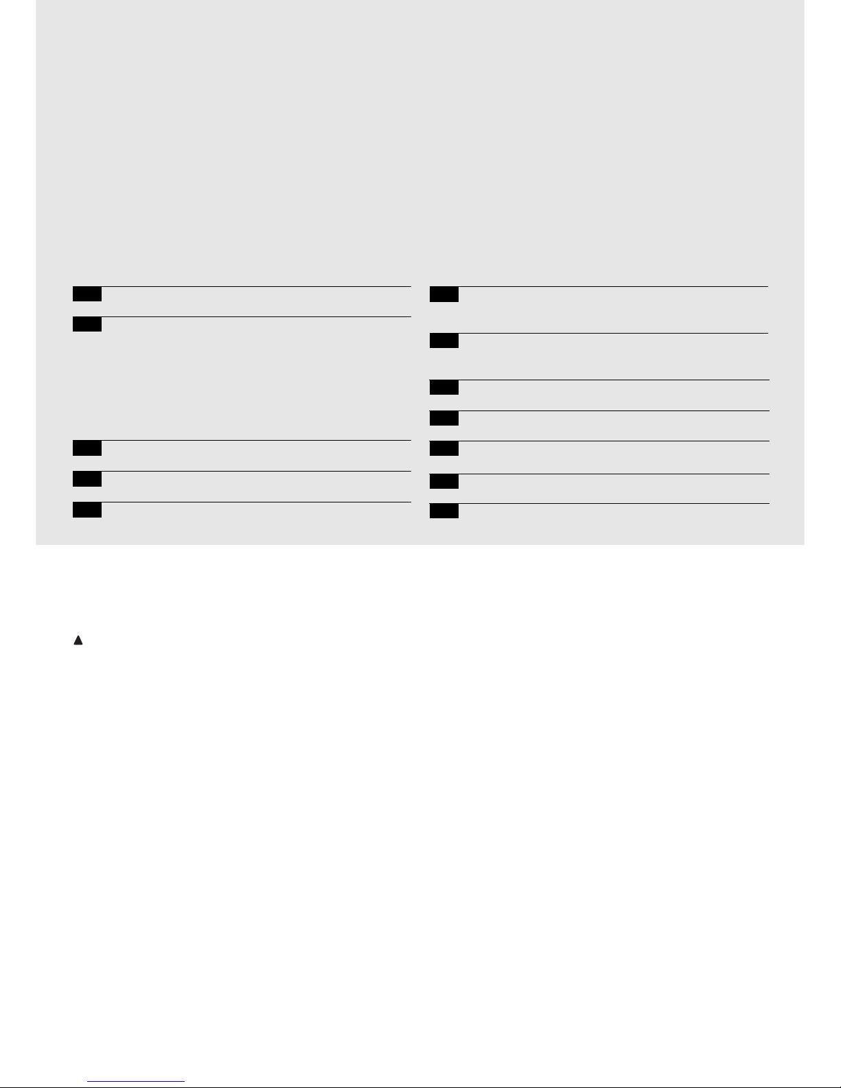
76
besturingseenheid
reductiemotors
robo, thor, otto
Aanbevelingen:
Deze handleiding is alleen bestemd voor gekwalificeerd
technisch personeel dat met de installatie belast is. Geen
enkele informatie uit deze handleiding kan als van belang
voor de eindgebruiker beschouwd te worden!
Deze handleiding heeft alleen betrekking op deze besturingseenheid en mag niet voor andere producten gebruikt worden.
Het verdient aanbeveling alle aanwijzingen tenminste éénmaal nauwkeurig door te lezen alvorens met de installering te beginnen.
!
Inhoudsopgave: pag.
1 Beschrijving van het product 17
2 Installatie 18
2.1 Voorbeeld van een installatie 18
2.2 Elektrische aansluitingen 18
2.2.1 Elektrisch schema 19
2.2.2 Beschrijving van de aansluitingen 19
2.2.3 Fototest 20
2.2.4 Controle van de aansluitingen 21
3 Afstellingen 21
4 Eindtest 22
5 Manier van functioneren 23
pag.
6 Programmeerbare functies 23
6.1 Beschrijving van de functies 24
7 Toepassing van 2 besturingseenheden op in
tegenovergestelde richting werkende vleugels 25
8 Apart leverbare accessoires 26
9 Onderhoud 26
10 Afvalverwerking 26
11 Wat te doen als… 27
12 Technische gegevens 27

NL
77
1) Beschrijving van het product:
Met deze besturingseenheid voor het automatiseren van automatische poorten en deuren kunnen de éénfasewisselstroomreductiemotoren ROBO, THOR, OTTO aangestuurd worden.
Al naar gelang het type aan te sturen reductiemotor verschillen de
besturingseenheden van elkaar, zoals bijvoorbeeld: "Afstelling
Kracht", "Controlelampje Poort Open " en “Gebruikerslicht”.
Er zijn bovendien een reeks functies die met behulp van dipschakelaars (microschakelaars) geselecteerd kunnen worden en afstellingen die met trimmers uitgevoerd kunnen worden.
De status van de ingangen wordt door speciale ledlampjes bij de
ingangen aangegeven; een ander ledlampje bij de microprocessor
geeft aan dat de interne logica correct functioneert.
Om de verschillende delen gemakkelijker te kunnen herkennen zijn
op afb.1 de belangrijkste onderdelen aangegeven.
Code Product* Code Besturingseenheid* Extra functie
ROBO
RO1000
RO1020
ROA3 Trimmer “Afstelling Kracht”
RO1010 ROA4 Relais “Start”
THOR
TH1551 THA5 Trimmer “Afstelling Kracht”
TH2251 THA6 Relais “Start”
OTTO OT21 OTA1 Uitgang “Gebruikerslicht”
* = voeg V1 aan de code toe voor uitvoering op 120 V 50/60 Hz
LMNOP
J
QRST
VU
I
X
W
Y
H
G
FZ
EDCBA
CH
P. P.
AP
FOTO
FCA
FCC
OK
Dipschakelaar voor het selecteren van de functies
Trimmer voor het afstellen van ” Kracht "
Trimmer voor het afstellen van Werkingsduur (TL)
Trimmer voor het afstellen van Pauzeduur (TP)
Klemmenbord voor Antenne en 2de kanaal
Insteekgleuf RADIO-kaart
Ledlampjes voor het aangeven van status ingangen
Klemmenbord Ingangen / Uitgangen voor instructie
Relais “Gemeenschappelijk”
Klemmenbord stroomvoorziening / Knipperlicht
Primaire connector transformator
Zekering lijn (5A)
Connector uitgang “Gebruikerslicht” (alleen op OTTO)
Uitgang stroomvoorziening motor
Connectorinsteekgleuf condensator
Relais “Start”
Triac “Gebruikerslicht” (alleen op OTTO)
Triac “Sluit”
Triac “Open”
Secundaire connector transformator
Ingang eindschakelaar FCA / FCC
Zekering laagspanning (500mA)
Insteekgleuf kaart PIU
Ledlampjes OK
Microprocessor
A
B
C
D
E
F
G
H
I
J
L
M
N
O
P
Q
R
S
T
U
V
W
X
Y
Z
1
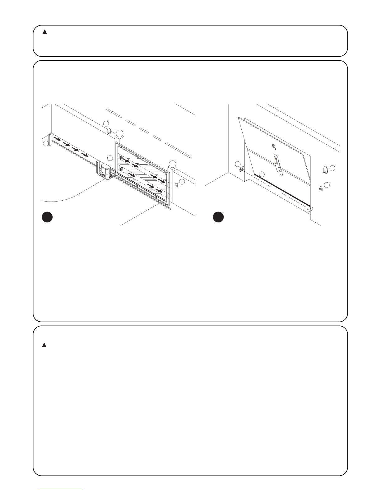
2.1) Voorbeeld van een installatie
Om enkele termen en aspecten van een automatiseringsinstallatie voor deuren of poorten te verduidelijken geven wij u hier een typisch voorbeeld.
ROBO en THOR OTTO
1) Stel fotocellen “Foto”
2) Knipperlicht
3) Sleutelschakelaar
4) Pneumatische lijst
5) Stel fotocellen “Foto 2”
Met name herinneren wij u aan het volgende:
• Alle door Nice geproduceerde fotocellen beschikken over een synchronisatiesysteem waarmee het mogelijk is het probleem van interferentie tussen twee stellen fotocellen op te lossen (zie voor verdere bijzonderheden de aanwijzingen voor de fotocellen).
• Het stel fotocellen "Foto" heeft bij het openen geen gevolgen terwijl het bij het sluiten ervoor zorgt dat de poort omkeert.
• Het stel fotocellen "Foto2” heeft bij het sluiten geen gevolgen terwijl het bij het openen ervoor zorgt dat de poort terugloopt.
78
2.2) Elektrische aansluitingen
Om de veiligheid van de installateur te waarborgen en
schade aan de componenten te voorkomen is het bij het
maken van de aansluitingen of het inpluggen van de verschillende kaarten absoluut noodzakelijk de besturingseenheid uit te schakelen.
• Sluit de besturingseenheid met een kabel van 3 x 1,5 mm
2
op het
net aan; als de afstand tussen de besturingseenheid en de aansluiting op de installatie meer dan 30 m bedraagt, dient u in de
buurt van de besturingseenheid voor aarding te zorgen.
• Bij aansluitingen in het op zeer lage veiligheidsspanning werkende
deel dient u kabeltjes met een minimumdoorsnede van 0,25 mm
2
te gebruiken.
• Gebruik afgeschermde kabeltjes als de lengte meer dan 30 m
bedraagt en aard het omhulsel alleen aan de zijde van de besturingseenheid.
• Maak geen aansluitingen op kabels in boxen onder de grond, ook
al zijn die helemaal waterdicht.
• De ingangen van de contacten van het type Normaal gesloten
(NC), indien niet gebruikt, dienen via een brug met "gemeenschappelijk 24V " verbonden te worden met uitzondering van de
ingangen van de fotocellen, indien de functie “Fototest” geactiveerd wordt. U gelieve voor verdere informatie de paragraaf "Fototest" te lezen.
• Als er voor dezelfde ingang meerdere contacten Normaal gesloten (NC) zijn, dan worden die onderling serieel geschakeld.
• De ingangen van de contacten van het type Normaal open (NO),
dienen, indien niet gebruikt, vrij gehouden te worden.
• Als er voor dezelfde ingang meerdere contacten Normaal open
(NO) zijn, dan worden die onderling parallel geschakeld.
• De contacten moeten mechanische contacten zijn en geen enkel
potentiaal hebben; aansluitingen in fasen zoals die welke "PNP",
"NPN", "Open Collector" etc. gedefinieerd worden, zijn niet toegestaan.
!
Wij brengen u hierbij in herinnering dat installaties met
automatische poorten en deuren uitsluitend door gekwalificeerd technisch personeel en met inachtneming van de
wettelijke voorschriften geïnstalleerd mogen worden. Volg
nauwgezet de aanbevelingen van het boekje: "Aanbevelingen voor de installateur".
!
2) Installatie:
2a
2b
FOTO
FOTO
FOTO 2
5
3
2
1
3
4
FOTO
2
1

NL
79
2.2.1) Elektrisch schema
SLUIT
OPEN
SLUIT
OPEN
STOP
Stroomvoorziening
via elektriciteitsnet
2.2.2) Beschrijving van de aansluitingen
Hier volgte een beknopte beschrijving van mogelijke aansluitingen van de besturingseenheid naar buiten.
Klemmetjes Functie Beschrijving
1-2 : Stroomvoorziening = Toevoerlijn van het elektriciteitsnet
3-4 : Knipperlicht = Uitgang voor aanslsuiting van het knipperlicht op de netspanning (Max. 40W)
5-6 : 24 Vac = Stroomvoorziening neveninrichtingen 24Vac (Foto, Radio, etc.) Max 200mA
7 : Gemeenschappelijk = Gemeenschappelijk voor alle ingangen
8 : Controlelampje P.O. (SCA) = “Controlelampje Poort Open” 24Vac max. 2W (Niet aanwezig op de uitvoering OTTO)
9 : Stop = Ingang met functie voor het onderbreken van de manoeuvre waarbij de richting eventjes
wordt omgekeerd
10 : Foto = Ingang voor veiligheidsinrichtingen (fotocellen, pneumatische lijsten)
11 : Stap-voor-stap (PP) = Ingang voor cyclische manoeuvre (“Open” - “Stop” - “Sluit” - “Stop”)
12 : Open = Ingang voor openingsmanoeuvre
13 : Sluit = Ingang voor sluitmanoeuvre
41-42 : 2° Ch Radio = Uitgang van een eventueel tweede kanaal van de radio-ontvanger
43-44 : Antenne = Ingang voor de antenne van de radio-ontvanger
3

80
2.2.3) Fototest
De "Fototest" verhoogt de betrouwbaarheid van de veiligheidsinrichtingen waardoor het mogelijk is "categorie 2" van de norm EN 9541 (uitgave 12/1998) te bereiken voor wat betreft de combinatie
besturingseenheid en veiligheidsfotocellen. Telkens wanneer er een
manoeuvre van start gaat, worden alle veiligheidsinrichtingen gecontroleerd en alleen als de test een positief resultaat geeft, gaat de
manoeuvre van start. Als de test daarentegen geen positief resultaat
heeft (fotocel door de zon verblind, kortsluiting kabels etc.) wordt de
storing gedetecteerd en de manoeuvre niet uitgevoerd.
Om de functie "Fototest" te verkrijgen zijn de volgende punten noodzakelijk:
• Gebruik de supplementaire kaart PIU
• Zet de dipschakelaar 10 op ON
• Sluit de veiligheidsinrichtingen aan zoals dat op afb. 4a te zien is
waarbij de stroomvoorziening van de zenders van de fotocellen
niet rechtstreeks via de uitgang van de neveninrichtingen plaats
vindt, maar door deze stroomvoorziening via de klemmetjes 7 en
8 op de kaart PIU te onderbreken.
De maximaal beschikbare stroom op de uitgang "Fototest" op de
kaart PIU is 100mA (2 stel fotocellen Nice).
• Voorzie de ontvangers rechtstreeks via de uitgang neveninrichtingen van de besturingseenheid (klemmetjes 5-6) van stroom.
Als u later de functie Fototest niet meer wilt gebruiken, behoeft u alleen
maar dipschakelaar 10 naar beneden te halen en de configuratie van de aansluitingen te wijzigen zoals dat op afb.4b is aangegeven.
Het testen van de fotocellen vindt als volgt plaats: wanneer er een
bedieningsopdracht voor een manoeuvre gegeven wordt, wordt er
eerst nagegaan of alle ontvangers die met deze manoeuvre van doen
hebben, hun ok geven; daarna wordt de stroomvoorziening naar de
zenders onderbroken en wordt vervolgens gecontroleerd of alle ontvangers dit feit signaleren door hun ok in te trekken; tenslotte wordt
de stroomvoorziening van de zenders weer ingeschakeld en wordt er
opnieuw gecontroleerd of alle ontvangers hun ok geven. Alleen als
deze serie controles een positief resultaat heeft, zal de manoeuvre
van start gaan. Het is raadzaam ook het synchronisme te activeren
door de bruggetjes op de zenders te doorbreken; dit is de enige
methode om ervoor te zorgen dat er tussen de twee stellen fotocellen geen interferentie plaats vindt. Controleer in de handleiding van
de fotocellen de aanwijzingen voor een gesynchroniseerde werking.
Indien een ingang die aan de "Fototest" onderworpen is, niet wordt
gebruikt (Voorbeeld "Foto2") en u toch de functie fototest wilt, dient
u een brug tussen de niet gebruikte ingang aan te brengen zoals dat
op afb.4c te zien is.
“Foto” en “Foto2” met “Fototest”
“Foto” en “Foto2” zonder “Fototest”
“Foto” met “Fototest”
4a
4b
4c
13
9107
658
(Kaart PIU)
9
8
10
11
12
7
78
9
11
10
12
(Kaart PIU)
13
9107
658
109
8
13
7
6
5
710PIU
PIU
811PIU
PIU
PIU 8
RX
43512
6
FOTO
5
10
7
RX
543
FOTO 2
21
6
5
(Kaart PIU)
7
RX
54321
6
FOTO
RX
10
7
(Kaart PIU)
FOTO 2
5
10PIU
6
7
5312 4
5
RX
34 512
6
10
7
5
FOTO
10PIU
PIU 11
RX
12
7
12
PIU
PIU
21
34 512
RX
53412
87
TX
10
12
11
9
(Kaart PIU)
12
TX
21
FOTO 2
FOTO
(Kaart PIU)
7
PIU
21
RX
423 5
6
5
5
6
21
RX
2345
TX
FOTO
21
TX
(Kaart PIU)
FOTO 2
12
1
1
12
712PIU
PIU
RX
34 512
TX
12
FOTO
12
PIU
TX
TX
TX
TX
TX

NL
81
2.2.4) Controle van de aansluitingen
Bij het uitvoeren van onderstaande handelingen werkt u met
onder spanning staande circuits. Op het merendeel van de circuits
staat laagspanning en daar bestaat dus geen gevaar, maar op sommige delen staat de spanning van het elektriciteitsnet, die dus
UITERST GEVAARLIJK zijn! Let heel goed op wat u doet en
WERK NOOIT ALLEEN!
• Sluit de stroomtoevoer op de besturingseenheid aan en controleer
onmiddellijk of er tussen de klemmetjes 5-6 een spanning van
ongeveer 24 Vac. aanwezig is.
• Controleer dat het ledlampje "OK" na eventjes snel geknipperd te
hebben, nu regelmatig knippert.
• Verifieer nu dat de ledlampjes van de ingangen van het type "NC"
(alle veiligheidsinrichtingen actief) branden, terwijl de bij de ingangen van het type "NO" behorende ledlampjes (geen enkele bedieningsopdracht aanwezig) uit zijn. Als dit niet het geval is, dient u te
controleren of de aansluitingen correct zijn uitgevoerd en de verschillende inrichtingen goed werken. De ingang "Stop" treedt in
werking door zowel de eindschakelaar FCA als de eindschakelaar
FCC uit te zetten.
• Verifieer of de eindschakelaars goed aangesloten zijn; haal de hen-
del van de eindschakelaar over en controleer of de desbetreffende
eindschakelaar in werking treedt, waarbij het bijbehorende ledlampje op de besturingseenheid uit gaat
• Ontgrendel de vleugel en breng die ongeveer halverwege, ver-
grendel deze; op deze manier kan de vleugel zowel bij het openen
als bij het sluiten vrij bewegen.
• Nu dient u te verifiëren of de manoeuvre in de juiste richting plaats
vindt, d.w.z. te controleren of de door de besturingseenheid doorgegeven manoeuvre overeenkomt met de daadwerkelijk door de
vleugels uitgevoerde manoeuvre. Deze controle is van fundamenteel
belang; als de richting in bepaalde gevallen niet juist is (bijvoorbeeld
in de semi-automatische modus), zou het erop kunnen lijken dat
het automatisme regelmatig functioneert; de cyclus ”open” is
immers gelijk aan de cyclus “Sluit” met dat fundamentele verschil
echter dat de veiligheidsinrichtingen genegeerd zullen worden bij de
sluitmanoeuvre - die normaal gesproken de gevaarlijkste is - en bij
opening in werking zullen treden, waardoor ze een hersluiting tegen
het obstakel zullen veroorzaken met desastreuze gevolgen!
• Om te controleren of de draairichting correct is, behoeft u alleen
maar een korte impuls op de ingang PP te geven; de eerste
manoeuvre die de besturingseenheid uitvoert nadat u haar onder
spanning gezet heeft is altijd "Open", dus kunt u ermee volstaan te
controleren of de automatisering een openingsmanoeuvre start.
Indien de manoeuvre in verkeerde richting wordt uitgevoerd ,dient
u als volgt te werk te gaan:
Schakel de stroomvoorziening uit
Draai de stekker voor stroomvoorziening van de motor met
180° evenals die van de eindschakelaars. (Ref. "O" en ref.
"V" op afb.1 )
Na afloop hiervan is het raadzaam opnieuw te kijken of de
draairichting in orde is; u begint hiervoor bij het laatste punt.
Het ledlampje "OK" op het midden van de kaart heeft tot taak de status van de interne logica aan te geven: wanneer het regelmatig knippert met
tussenpozen van 1 seconde wil dit zeggen dat de interne microprocessor
actief is en in afwachting is van een bedieningsopdracht. Wanneer de microprocessor een wijziging in de status van een ingang constateert (zowel een
bedieningsingang als een dipschakelaar voor een functie), gaat het lampje
tweemaal snel knipperen, ook als die wijziging geen onmiddellijk gevolg heeft.
Snel knipperen gedurende 3 seconden wil zeggen dat de besturingseenheid
zojuist onder spanning is gezet en een test op de interne onderdelen uitvoert;
onregelmatig knipperen wil zeggen dat de uitslag van de test niet positief is en
dat er dus een storing is opgetreden.
!
Afstellingen vinden plaats via trimmers die voor wijziging van onderstaande parameters zorgen:
Werkingsduur (TL):
Hiermee wordt de maximale tijdsduur van de openings- of sluitmanoeuvre afgesteld. Voor de afstelling van de TL, selecteert u de
werkingsmodus "Semi-automatisch" door de dipschakelaar 1 op ON
te zetten en vervolgens de trimmer TL halverwege te zetten. Voer bij
deze afstellingen een openings- en sluitingscyclus uit en stel de trimmer TL eventueel zodanig bij, dat er voldoende tijd is om de gehele
manoeuvre uit te voeren en er ook nog een zekere speling van 2 of
3 seconden overblijft. Indien er niet genoeg tijd is om de gehele
manoeuvre uit te voeren, ook al hebt u de trimmer TL op het maximum gezet, dient u de brug TLM die zich op de print tussen de trimmers TL en TP bevindt, te verbreken om de Werkingsduur te verlengen teneinde een Langere Werkingsduur (TLM) te verkrijgen.
Pauzeduur (TP):
Bij "automatische" werking wordt met deze functie de tijd tussen het
einde van de openingsmanoeuvre en het begin van de sluitmanoeuvre afgesteld. Om de TP af te stellen selecteert u de werkingsmodus
"Automatisch" door de dipschakelaar 2 op ON te zetten en vervolgens de trimmer TP naar wens af te stellen. Om dit te controleren
dient u een openingsmanoeuvre uit te voeren en daarna de tijd te
controleren die er tot de "Automatische" hersluiting verstrijkt.
Kracht (F):
Op de besturingseenheid kunt u de waarde van de maximale
"Kracht" afstellen.
Speciale aandacht dient u aan de afstelling van de trimmer "Kracht"
(F) te schenken; deze afstelling kan van invloed zijn op de graad van
veiligheid van de automatisering. Voor het afstellen hiervan dient u
proefondervindelijk te werk te gaan door meerdere malen achter
elkaar de door de vleugel toegepaste kracht te meten en deze te vergelijken met wat de voorschriften gebieden.
Bij de besturingseenheden voor RO1010 en OT21 wordt de "Kracht"
afgesteld via een keuzeschakelaar met meerdere standen op de
behuizing van de voedingstransformator van de besturingseenheid.
3) Afstellingen:
TP
TL
F
TLM

82
Nadat u een en ander gecontroleerd en afgesteld hebt, kunt u tot de eindtest van de installatie overgaan.
De eindtest van de automatisering moet door vakbekwaam en deskundig personeel uitgevoerd worden, dat ook bepa-
len moet welke tests in functie van de bestaande gevaren noodzakelijk zijn.
De eindtest is de belangrijkste fase bij de aanleg van de automatisering. Elk afzonderlijk onderdeel, bijvoorbeeld de reductiemotor, noodstop,
fotocellen en andere veiligheidsinrichtingen kunnen een specifieke eindtestfase vragen; het is daarom raadzaam de procedures uit de desbetreffende handleidingen zorgvuldig uit te voeren.
Voor de eindtest van de besturingseenheid dient u onderstaande reeks handelingen uit te voeren:
1. Selectie functies:
• Zet de dipschakelaar 1 op ON (“Semi-automatische” modus)
• Als de aansluitingen van afb.4a tot stand gebracht zijn, dient u om de functie "Fototest" uit te laten voeren
(als er een kaart PIU aanwezig is), de dipschakelaar 10 (Functie "Fototest") op ON te zetten.
• Zet alle andere dipschakelaars op OFF
2. Druk op de instructietoets “Open” of “Stap-voor-Stap” en controleer of:
• het knipperlicht gaat knipperen
• er een openingsmanoeuvre van start gaat
• de poort stopt wanneer hij de eindschakelaar open FCA bereikt.
3. Druk op de instructietoets “Sluit” of “Stap-voor-Stap” en controleer of:
• het knipperlicht gaat knipperen
• er een sluitmanoeuvre van start gaat
• de poort stopt wanneer hij de eindschakelaar dicht FCC bereikt.
4. Laat een openingsmanoeuvre van start gaan en controleer dat er tijdens deze manoeuvre een inrichting in werking treedt die:
• aangesloten op de ingang “Stop'”, de manoeuvre onmiddellijk onderbreekt en een korte omkering van de beweging veroorzaakt
• aangesloten op de ingang “Foto”, geen enkel gevolg heeft
• aangesloten op de ingang “Foto2”, ervoor zorgt dat de manoeuvre onderbroken wordt en in tegengestelde richting hervat wordt
(als er een kaart PIU aanwezig is)
5. Laat een sluitmanoeuvre van start gaan en controleer dat er tijdens deze manoeuvre een inrichting in werking treedt die:
• Aangesloten op de ingang “Stop”, de manoeuvre onmiddellijk onderbreekt en een korte omkering van de beweging veroorzaakt
• aangesloten op de ingang “Foto”, ervoor zorgt dat de manoeuvre onderbroken wordt en in tegengestelde richting hervat wordt
• aangesloten op de ingang “Foto2”, geen enkel gevolg heeft (als er een kaart PIU aanwezig is)
6. Controleer op de aangesloten ingangen of de activering van de ingang een stap in onderstaande reeks ten gevolge heeft:
• Ingang “Stap-voor-stap”: Reeks = “Open” - “Stop” - “Sluit” - ”Stop”
• Ingang “Open”: Reeks = “Open” - “Stop” - “Open” - “Stop”
• Ingang “Sluit”: Reeks = “Sluit” - “Stop” - “Sluit” - “Stop”
• Ingang “Gedeeltelijk Open”: Reeks = “Gedeeltelijk open” - “Stop” - “Sluit” - “Stop” (indien kaart PIU aanwezig is).
7 Controleer als de functie fototest gebruikt wordt, of deze test goed werkt (als de kaart PIU aanwezig is):
• Onderbreek de fotocel “Foto”, laat vervolgens een manoeuvre van start gaan en verifieer dat die manoeuvre niet wordt uitgevoerd
• Onderbreek de fotocel “Foto2”, laat vervolgens een manoeuvre van start gaan en verifieer dat die manoeuvre niet wordt uitgevoerd
• Breng het contact van de fotocel “Foto” in kortsluiting, laat vervolgens een manoeuvre van start gaan en verifieer dat die manoeuvre
niet wordt uitgevoerd
• Breng het contact van de fotocel “Foto2” in kortsluiting, laat vervolgens een manoeuvre van start gaan en verifieer dat die
manoeuvre niet wordt uitgevoerd.
8. Voer de tests uit om de stootkrachten te meten zoals die in de norm EN 12445 voorzien zijn.
Als er na uitvoering van de eindtest andere functies worden geactiveerd die de veiligheid van de installatie kunnen doen afnemen, dient er
een voor die functies specifieke eindtest uitgevoerd te worden.
!
4) Eindtest

NL
83
5) Manier van functioneren
Bij werking in de handbediende modus vindt er via de ingang “Open”
een openingsmanoeuvre plaats en via de ingang ”Sluit” een sluitmanoeuvre. Via de ingang “Stap-voor-Stap” vindt er beurtelings een
openings- en sluitmanoeuvre plaats.
Zodra de binnenkomende instructie stopt, wordt de manoeuvre
onderbroken. Bij opening wordt de manoeuvre onderbroken wanneer de eindschakelaars in werking treden of als er geen toestemming van “Foto2” (op de kaart PIU) is; bij sluiting daarentegen wordt
de manoeuvre onderbroken, als er geen toestemming is van “Foto”.
Zowel bij opening als bij sluiting zorgt “Stop” er altijd voor dat de
manoeuvre onmiddellijk wordt onderbroken. Wanneer de manoeuvre
onderbroken is, dient de binnenkomende instructie gestopt te worden alvorens een nieuwe instructie een nieuwe manoeuvre kan
bewerkstelligen. Bij werking in één van de automatische modi
(“Semi-automatisch”, “Automatisch” of “Altijd sluiten”) veroorzaakt
een bedieningsimpuls op de ingang “Open” een openingsmanoeuvre. Een impuls op “Stap-voor-Stap” zorgt ervoor dat de poort beurtelings open of dicht gaat. Een tweede impuls op “Stap-voor-Stap”
of op dezelfde ingang die de manoeuvre gestart heeft, veroorzaakt
een “Stop”. Zowel bij opening als bij sluiting zorgt “Stop” er altijd voor
dat de manoeuvre onmiddellijk wordt onderbroken en dat de poort
eventjes terugloopt.
Als er op een instructie-ingang in plaats van een impuls een doorlopend signaal wordt gegeven, ontstaat er een status van "voorkeur"
waarbij de andere instructie-ingangen uitgeschakeld blijven (nuttig
voor het aansluiten van een tijdschakelaar of een keuzeschakelaar Dag-Nacht).
Indien de automatische modus geselecteerd wordt, is er na een openingsmanoeuvre een pauze, waarna een sluitmanoeuvre plaats vindt.
Als “Foto” tijdens de pauze in werking treedt, wordt de timer met een
nieuwe Pauzeduur teruggesteld; als “Stop” tijdens de pauze in werking treedt, wordt de functie van terugloop gewist en komt de installatie in “Stop”. Bij opening heeft het inwerkingtreden van ”Foto” geen
enkele effect, terwijl “Foto2” (op de kaart PIU) ervoor zorgt dat de
beweging tijdelijk onderbroken wordt; bij sluiting zorgt inwerkingtreding van “Foto” voor een omkering van de beweging, daarna een
pauze en vervolgens weer sluiting.
De besturingseenheid beschikt over een serie microschakelaars
waarmee u de verschillende functies kunt activeren om de installatie
zoveel mogelijk aan de eisen van de gebruiker aan te passen en deze
in de verschillende gebruikssituaties zo veilig mogelijk te maken.
De functies worden geactiveerd door de desbetreffende dipschakelaar op de stand "On" te zetten, terwijl de functies waarvan de desbetreffende dipschakelaar op "Off'' staat, niet geactiveerd worden.
Sommige programmeerbare functies zijn verbonden aan
veiligheidsaspecten, overweeg aandachtig de gevolgen
van een bepaalde functie en controleer welke functie de
grootste mogelijke veiligheid biedt.
!
Met de dipschakelaars kunt u de verschillende manieren van functioneren selecteren en de gewenste functies volgens onderstaande tabel invoeren:
Schakelaar 1-2: Off-Off = "Handbediende" manoeuvre, d.w.z. er is iemand aanwezig
On -Off = "Semi-automatische" manoeuvre
Off-On = "Automatische" manoeuvre, d.w.z. automatische sluiting
On -On = Manoeuvre "Automatisch + altijd sluiten"
Schakelaar 3: On = Werking Woningblok < niet beschikbaar in handbediende modus >
Schakelaar 4: On = Voorwaarschuwing
Schakelaar 5: On =
Terugloop 5' na Foto < bij “Automatisch” > of Sluit na Foto < bij “Semi-automatisch” >
Schakelaar 6: On = Beveiliging "Foto" ook bij opening
Schakelaar 7: On = Geleidelijke start
Schakelaar 8: On = Vertraging
Schakelaar 9: On = Rem
Schakelaar 10: (op Robo) On = Controlelampje Poort Open (SCA) met proportioneel knipperen
Zonder kaart PIU
(op Otto) On = Duur gebruikerslicht = 4 minuten
Met kaart PIU On = Functie “Fototest”
N.B.: Sommige functies zijn onder bepaalde omstandigheden mogelijk, deze zijn aangegeven met de tussen de tekens "<...>" staande
opmerkingen.
6) Programmeerbare functies
101

84
6.1) Beschrijving van de functies
Hieronder geven wij een beknopte beschrijving van de functies die ingeschakeld kunnen worden door de desbetreffende dipschakelaar op
"On" te zetten.
Schakelaar 1-2: Off-Off = "Handbediende" manoeuvre (er is iemand aanwezig)
On-Off = "Semi-automatische" manoeuvre
Off-On = "Automatische" manoeuvre (automatische sluiting)
On-On = Manoeuvre "Automatisch + Sluit altijd "
Bij de "Handbediende" modus wordt de manoeuvre alleen uitgevoerd zolang de instructie aanwezig is (toets ingedrukt).
Bij "Semi-automatisch" is een instructie-impuls voldoende en wordt de gehele manoeuvre uitgevoerd totdat de Werkingsduur verlopen is of
de eindschakelaar bereikt is. Bij "Automatische" werking is er na een openingsmanoeuvre een pauze waarna de sluiting automatisch uitgevoerd wordt.
De functie "Sluit altijd " treedt in werking na een storing in de stroomvoorziening, waarbij automatisch een sluitmanoeuvre uitgevoerd wordt
na een voorwaarschuwing van 5 seconden.
Schakelaar 3: On = Werking Woningblok (niet beschikbaar in handbediende modus)
Bij de functie Woningblok kan de manoeuvre, zodra de openingsmanoeuvre van start gegaan is, niet door andere bedieningsimpulsen op
“Stap-voor-Stap” of “Open” onderbroken worden zolang de openingsmanoeuvre nog niet beëindigd is.
Tijdens een sluitmanoeuvre zal een nieuwe bedieningsimpuls de poort laten stoppen en zal de poort weer open gaan.
Schakelaar 4: On = Voorwaarschuwing
Bij het ontvangen van een bedieningsimpuls wordt eerst het waarschuwingslicht geactiveerd en vervolgens gaat na 5 seconden (2 bij bediening met de hand), de manoeuvre van start.
Schakelaar 5: On = Terugloop 5" na Foto <indien in “Automatisch” > of Sluiten na Foto <indien in “Semi-automatisch”>
Met behulp van deze functie kunt u, indien in “Automatisch”, de poort zolang openhouden als nodig is om er doorheen te gaan; nadat “Foto”
in werking is gekomen, wordt de manoeuvre onderbroken. Na 5 seconden zal er automatisch een sluitmanoeuvre van start gaan. Indien in
Semi-automatisch, zal het inwerkingtreden van “Foto” tijdens de sluitmanoeuvre de automatische sluiting met de ingestelde Pauzeduur activeren.
Schakelaar 6: On = Beveiliging “Foto” ook bij opening
Normaal gesproken is de beveiliging "Foto" alleen tijdens de sluitmanoeuvre geactiveerd; als de schakelaar 6 op "On" wordt gezet, wordt de
manoeuvre door het in werking treden van de veiligheidsinrichting onderbroken, ook bij het openen.
Indien in “Semi-automatisch” of “Automatisch” zal de openingsmanoeuvre, zodra de beveiliging vrijkomt, weer hervat worden
Schakelaar 7: On = Geleidelijke start
Hiermee verloopt het begin van de manoeuvre geleidelijk zodat de automatisering geen ongewenste schokken krijgt te verduren
Schakelaar 8: On = Vertraging
De vertraging bestaat uit een snelheidsvermindering op 30% van de nominale snelheid zodat onnodige schokken aan het einde van de
manoeuvre voorkomen kunnen worden.
De functie Vertraging behalve dat die de snelheid van de automatisering doet afnemen, reduceert ook met 70% het koppel van de motoren.
In automatiseringen die een hoog koppel vereisen, kan het feit dat het koppel dermate wordt teruggebracht, tot gevolg hebben dat de motor onmiddellijk stopt.
Uitvoering voor ROBO en THOR:
Aan het einde van de openings- of sluitmanoeuvre op grond van de
Werkingsduur wordt er een vertragingsfase uitgevoerd die net zolang
als de Werkingsduur duurt.
Als de manoeuvre stopt als gevolg van het inwerking treden van de
eindschakelaars, wordt de vertragingsfase niet uitgevoerd; u dient
dan de Werkingsduur af te stellen om de vertraging 30-50 cm voor
het inwerkingtreden van de eindschakelaars te laten beginnen.
Uitvoering voor OTTO:
Aan het einde van de sluitmanoeuvre duurt de vertragingsfase 3 s.,
indien die het gevolg is van het in werking treden van de eindschakelaars en net zolang als werkingtijd indien die het gevolg is van het einde van de werkingsduur (voor het goed laten werken van de vertraging is het raadzaam eindschakelaars te gebruiken.
Bij de openingsfase wordt er geen vertraging maar een geleidelijke
stop uitgevoerd.
Als u de vertragingsfunctie op gevoelige installaties
gebruikt en als die langer dan 3 S. duurt is het absoluut
noodzakelijk in de nabijheid van de besturingseenheid een
netfilter van tenminste 6A met een verlaging van 30dB op
de klemmetjes van de netvoeding aan te brengen om de
door de norm EN 50081-1 voorgeschreven limieten van
elektromagnetische uitstraling niet te overschrijden.
!

NL
85
Schakelaar 9: On = Rem
Aan het einde van de manoeuvre wordt er een remprocedure op de motor uitgevoerd, aanvankelijk lichtjes, maar dan steeds duidelijker om
de poort snel maar zonder schokken te laten stoppen.
Met behulp van deze functie kunt u elke keer bij de aanvang van een manoeuvre controleren of de fotocellen goed werken. Zie het hoofdstuk "Fototest"
Om een automatisering met 2 vleugels die in tegenovergestelde richting werken aan te leggen dient u als volgt te werk te gaan:
• Gebruik twee motoren waarvan de besturingseenheden aangeslo-
ten zijn zoals u dat op afb.5 kunt zien.
• Sluit het waarschuwingslicht en het "Controlelampje Poort Open”
op één van de twee besturingseenheden, onverschillig welke, aan.
• De ingangen moeten onderling parallel geschakeld worden.
• Het "Gemeenschappelijk" van de ingangen kan op één van de 2
besturingseenheden worden aangesloten.
• Sluit de 0Volt (Klemmetje 5) van de twee besturingseenheden op
elkaar aan.
• De functie "Fototest" mag niet gebruikt worden.
• Het is raadzaam de functie "Woonblok" in werking te stellen (dipschakelaar 3) waarmee de 2 vleugels weer synchroon kunnen werken, mochten de 2 besturingseenheden niet meer synchroon werken
7) Toepassing van twee besturingseenheden op in tegenovergestelde richting werkende vleugels
Stroomvoorziening
via elektriciteitsnet
Stroomvoorziening
via elektriciteitsnet
SLUIT
OPEN
SLUIT
OPEN
SLUIT
OPEN
STOP
Schakelaar 10: On
ROBO en THOR
Zonder ingeplugde kaart PIU:
• "Controlelampje Poort Open " met proportioneel knipperen
Met ingeplugde kaart PIU:
• “Fototest”
OTTO
Zonder ingeplugde kaart PIU:
• Duur “Gebruikerslicht” = 4 minuten
Met ingeplugde kaart PIU:
• “Fototest”
5

86
Kaart PIU
De besturingseenheid omvat reeds alle functies die bij een normale installatie gebruikt worden. Om tegemoet te komen aan de eisen bij
speciale installaties is de speciale kaart PIU ontwerpen waarmee u nieuwe functies aan de installatie kunt toevoegen zoals verkeerslichten,
gebruikerslampje, Elektroslot, "Foto2", gedeeltelijke opening en "Fototest".
Rood = Rood licht van het verkeerslicht
Gewoonlijk is dat altijd uit, maar het gaat branden wanneer de poort open of dicht gaat.
Groen = Groen licht van het verkeerslicht
Dit blijft gewoonlijk branden, maar het dooft wanneer de poort open of dicht gaat.
Elektroslot = Uitgang voor instructie elektroslot.
Het elektroslot wordt gedurende 1,5 s aan het
begin van de openingsmanoeuvre geactiveerd
Gebruikerslicht/
Fototest = Uitgang waarmee u als u dat gebruikt voor de
instructie gebruikerslampje, aan het begin van
elke manoeuvre een Gebruikerslampje kunt laten
branden dat tot na afloop van de manoeuvre blijft
branden en wel zolang als met de trimmer Tijd
Gebruikerslampje op de kaart PIU geprogrammeerd is.
Gebruikerslicht aanwezig op de kaart PIU.
Als u de functie "Fototest" (dipschakelaar 10 =
ON) activeert, maakt deze uitgang het mogelijk
de fotocellen bij het begin van alle manoeuvres te
testen.
Open gedeeltelijk = Ingang voor gedeeltelijke opening
("Gedeeltelijke opening" "Stop", "Sluit",
"Stop"). Deze functie doet hetzelfde als de
functie "Stap-voor-Stap" op de hoofdkaart,
met dat verschil dat de manoeuvre "Open"
zolang duurt als via de trimmer "Tijd Gedeeltelijke opening " op de kaart PIU is ingesteld.
Foto 2 = Ingang 2de veiligheidsinrichting. Deze
inrichting treedt alleen bij een openingsmanoeuvre in werking en zorgt ervoor dat de
manoeuvre onderbroken wordt, waarbij de
poort eventueel gesloten wordt als de werkingsmodus "Semi-automatisch" of "Automatisch" op de besturingseenheid geprogrammeerd is.
24 V = Uitgang 24V die gebruikt kan worden om
de neveninrichtingen zoals fotocellen of
andere van stroom te voorzien. Het klemmetje 11 is ook gemeenschappelijk voor de
ingangen .
RADIO-kaart
De besturingseenheid beschikt over een insteeksleuf voor het insteken van een Nice-radiokaart, waardoor het mogelijk is de ingang "Stapvoor-stap" te gebruiken en zo de besturingseenheid via een zender op afstand te bedienen.
8) Apart leverbare accessoires
Voor de besturingseenheid als elektronische component is geen
enkel speciaal onderhoud vereist. Controleer echter periodiek (tenminste eens in het half jaar), of de afstellingsinrichting van de Kracht
van de motor nog goed werkt; gebruik eventueel de trimmer om een
en ander bij te stellen.
Voer de eindtest in zijn geheel opnieuw uit om te controleren of de
veiligheidsinrichtingen (fotocellen, pneumatische lijsten, etc.) en het
waarschuwingslicht correct functioneren.
9) Onderhoud
Dit product bestaat uit verschillende soorten materialen, waarvan
sommige gerecycleerd kunnen worden.
Win inlichtingen over de methoden van hergebruik of afvalverwerking
in en houd u aan de plaatselijk van kracht zijnde voorschriften.
Sommige elektronische onderdelen zouden vervuilende
stoffen kunnen bevatten: laat ze niet in het milieu verdwijnen.
!
10) Afvalverwerking

NL
87
Dit is bedoeld als een richtlijn voor de installateur om hem te helpen
bij het oplossen van de problemen die zich tijdens de installatie kunnen voordoen.
Er brandt geen enkele ledlampje
• Controleer of de besturingseenheid onder spanning staat (controleer dat er op de klemmetjes 1-2 de spanning van het elektriciteitsnet staat en op de klemmetjes 5-6 een spanning van ongeveer 24Vac).
• Controleer of de 2 zekeringen op de stroomvoorziening intact zijn,
en als er ook nu geen enkel ledlampje brandt, zal het hoogst waarschijnlijk om een ernstige storing gaan en zal de besturingseenheid
vervangen dienen te worden.
Het ledlampje OK knippert regelmatig maar de ledlampjes
INGANGEN komen niet met de status van de betreffende
ingangen overeen
• Controleer nauwkeurig de aansluitingen op de klemmetjes van
de ingangen 7÷13.
De manoeuvre gaat niet van start
• Controleer dat de ledlampjes van de beveiligingen "Stop" (FCA +
FCC), "Foto", en eventueel "Foto2" branden en dat het ledlampje
van de instructie die geactiveerd wordt ("Stap-voor-Stap", "Open"
of "Sluit") brandt, zolang de instructie gegeven wordt.
Tijdens de manoeuvre voert de poort een terugloop uit
De oorzaken voor het teruglopen zijn:
• De fotocellen “Foto 2” bij opening en “”Foto”” bij sluiting treden in
werking; controleer in dit geval de aansluitingen van de fotocellen
en verifieer eventueel de signaleringledlampjes van de ingangen.
11) Wat te doen als…
Stroomvoorziening via elektriciteitsnet : 230 Vac 50/60 Hz
Uitvoeringen /V1 : 120 Vac 50/60 Hz
Max. stroom neveninrichtingen 24 V : 200mA
Uitgang knipperlicht : Voor waarschuwingslichten op netspanning, maximumvermogen 40 W
Uitgang controlelampje poort open “SCA” : Voor controlelampjes 24Vac, maximumvermogen 2 W
Bedrijfstemperatuur : -20 ÷ 70 °C
Werkingsduur ROBO/THOR : Instelbaar van 2,5 tot > 60 s, oppure da < 50 a > 120 s met TLM
Werkingsduur OTTO : Instelbaar van 2,5 tot > 20 s, of van < 20 tot > 40 s met TLM
Pauzeduur : Instelbaar van 5 tot > 160 s.
op Kaart PIU
Duur Ged.Open ROBO/THOR : Instelbaar van 1 tot > 30 s.
Duur Ged. Open OTTO : Instelbaar van 1 tot > 14 s.
Duur gebruikerslicht : Instelbaar van 1 tot > 180 s.
12) Technische gegevens

(secondo Direttiva 98/37/EC, Allegato II, parte B) (according to 98/37/EC Directive, Enclosure II, part B)
Numero /Number: 131/RO-TH-OT Data / Date: 9/2001 Revisione / Revision: 3
Il sottoscritto Lauro Buoro, Amministratore Delegato, dichiara che il prodotto: / The undersigned Lauro Buoro, General Manager, declares that the product:
Nome produttore / Producer name:
NICE s.p.a.
Indirizzo / Address: Via Pezza Alta 13, 31046 Z.I. Rustignè - ODERZO- ITALY
Tipo / Type: Motoriduttore elettromeccanico 230 V.a.c. per cancelli scorrevoli / Electromechanical gear motor for sliding doors
Modello / Model: RO1000, RO1010, RO1020, TH1551, TH2251, OT21
Accessori / Accessories:
Scheda PIU, Ricevitore radio opzionale mod. K, BIO, FLO, FLOR / PIU Board, Optional Radio receiver mod. K, BIO, FLO, FLOR
Risulta conforme a quanto previsto dalle seguenti direttive comunitarie / Complies with the following community directives
Riferimento n° Titolo
Reference n° Title
73/23/CEE, 93/68/CEE DIRETTIVA BASSA TENSIONE e successiva modifica/ Low Voltage Directive and subsequent modification
89/336/CEE DIRETTIVA COMPATIBILITA’ ELETTROMAGNETICA (EMC) / EMC Electromagnetic Compatibility Directive
98/37/CE (EX 89/392/CEE) DIRETTIVA MACCHINE / Machinery Directive
Risulta conforme a quanto previsto dalle seguenti Norme armonizzate / Complies with the following Harmonised standards
Riferimento n° Edizione Titolo
Livello di valutazione
Classe
Reference n° Issue Title Assessment level Class
EN60335-1 04/1998 Sicurezza degli apparecchi elettrici d’uso domestico e similare – Norme generali.
Safety of household and electrical appliances – General requirements
EN60204-1 09/1993 Sicurezza del macchinario-Equipag. elettrico delle macchine-Parte 1:Reg.generali
Safety of machinery-Electrical equipment of machines-Part 1:General requirements
EN55022 09/1998 Apparecchi per la tecnologia dell’informazione. Caratteristiche di radiodisturbo. Limiti e metodi di misura B
Information technology equipment – Radio disturbance characteristics Limits and methods of measurement
ENV50204 04/1996 Campo elettromagnetico irradiato dai radiotelefoni numerici - Prova di immunità. 10V/m A
Radiated electromagnetic fields from digital radio telephones - Immunity test
EN61000-3-2-3 03/1995 Parti 2-3: Armoniche/Flicker A
Parts 2-3: Harmonic/Flicker
Compatibilità elettromagnetica (EMC) / Electromagnetic compatibility (EMC)
Parte 4: Tecniche di prova e di misura / Part 4: Testing and measurement techniques
EN61000-4-2 09/1996 Parte 2: Prove di immunità a scarica elettrostatica 6KV, 8KV B
Part 2: Electrostatic discharge immunity test
EN61000-4-3 11/1997 Parte 3: Prova d’immunità sui campi irradiati a radiofrequenza 10V/m, A
Part 3: Radiated, radio-frequency, electromagnetic field immunity test
EN61000-4-4 09/1996 Parte 4: Test sui transienti veloci/ immunità ai burst 2KV, 1KV B
Part 4: Electrical fast transient/burst immunity test.
EN61000-4-5 06/1997 Parte 5: Prova di immunità ad impulsi 4KV, 2KV B
Part 5: Surge immunity test
EN61000-4-6 11/1997 Parte 6: Immunità ai disturbi condotti, indotti da campi a radiofrequenza 10V A
Part 6: Immunity to conducted disturbances, induced by radio-frequency fields.
EN61000-4-8 06/1997 Parte 8: Prova di immunità a campi magnetici a frequenza di rete 30A/m A
Part 8: Power frequency magnetic field immunity test.
EN61000-4-11 09/1996
Parte 11: Prove di immunità a buchi di tensione, brevi interruzioni e variazioni di tensione
B-C
Part 11: Voltage dips, short interruptions and voltage variations immunity tests
Risulta conforme a quanto previsto dalle altre norme e/o specifiche tecniche di prodotto / Complies with the other standards and/or product technical
specifications
Riferimento n° Edizione Titolo
Livello di valutazione
Classe
Reference n° Issue Title Assessment level Class
EN 12445 11/2000 Industrial, commercial and garage doors and gates - Safety in use of power
operated doors - Test methods
EN 12453 11/2000 Industrial, commercial and garage doors and gates - Safety in use of power
operated doors - Requirements
Inoltre dichiara che non è consentita la messa in servizio del prodotto suindicato finché la macchina, in cui il prodotto stesso è incorporato,
non sia identificata e dichiarata conforme alla direttiva 89/392/CEE / The above-mentioned product cannot be used until the machine into which it is
incorporated has been identified and declared to comply with the 89/392/EEC directive.
Il prodotto suindicato si intende parte integrante di una delle configurazioni di installazione tipiche, come riportato nei nostri cataloghi generali
/ The above product is an integral part of one of the typical installation configurations as shown in our general catalogues
Oderzo, li 11 Settembre 2001
(Amministratore Delegato)
(General Manager)
Lauro Buoro
Dichiarazione CE di conformità / EC declaration of conformity
IST106.4858 REV. 03 del 28-02-2005
Nice SpA
Oderzo TV Italia
Tel. +39.0422.85.38.38
Fax +39.0422.85.35.85
info@niceforyou.com
Nice Padova
Sarmeola di Rubano PD Italia
Tel. +39.049.89.78.93.2
Fax +39.049.89.73.85.2
infopd@niceforyou.com
Nice Roma
Roma Italia
Tel. +39.06.72.67.17.61
Fax +39.06.72.67.55.20
inforoma@niceforyou.com
Nice France
Buchelay
Tel. +33.(0)1.30.33.95.95
Fax +33.(0)1.30.33.95.96
Nice Rhône-Alpes
Decines Charpieu France
Tel. +33.(0)4.78.26.56.53
Fax +33.(0)4.78.26.57.53
Nice France Sud
Aubagne France
Tel. +33.(0)4.42.62.42.52
Fax +33.(0)4.42.62.42.50
Nice Belgium
Leuven (Heverlee)
Tel. +32.(0)16.38.69.00
Fax +32.(0)16.38.69.01
info@be.niceforyou.com
Nice España Madrid
Tel. +34.9.16.16.33.00
Fax +34.9.16.16.30.10
info@es.niceforyou.com
Nice España Barcelona
Tel. +34.9.35.88.34.32
Fax +34.9.35.88.42.49
info@es.niceforyou.com
Nice Polska
Pruszków
Tel. +48.22.728.33.22
Fax +48.22.728.25.10
info@pl.niceforyou.com
Nice UK
Chesterfield
Tel. +44.87.07.55.30.10
Fax +44.87.07.55.30.11
info@uk.niceforyou.com
Nice China
Shanghai
Tel. +86.21.575.701.45/46
Fax +86.21.575.701.44
info@cn.niceforyou.com
www.niceforyou.com
Nice Gate is the doors and gate automation division of Nice Nice Screen is the rolling shutters and awnings automation division of Nice
 Loading...