


Solemyo
EN - Installation and use instructions and warnings
IT - Istruzioni ed avvertenze per l’installazione e l’uso
FR - Instructions et avertissements pour l’installation et l’utilisation
ES - Instrucciones y advertencias para la instalación y el uso
DE - Anweisungen und Hinweise für die Installation und die Bedienung
PL - Instrukcje instalacji i użytkowania i ostrzeżenia
NL - Aanwijzingen en aanbevelingen voor installering en gebruik
Autonomous power system
SYKCE
PSY24


The design and manufacture of the devices making up the Solemyo
system and the information in this manual fully comply with current
standards governing safety. However, incorrect installation or programming may cause serious physical injury to those working on or using
the system. For this reason, during installation, always strictly observe
all instructions in this manual.
If in any doubt regarding installation, do not proceed and contact the Nice
Te ch n ic a l A ss i st a nc e f o r c la r if i ca t io n s.
WORKING IN SAFETY!
Warning – for personal safety it is important to observe these
instructions.
Warning – Important safety instructions: keep these instructions
in a safe place.
Observe the following warnings:
–make electrical connections exclusively as envisaged in this manual
incorrect: connections could cause serious damage to the system.
–If the power cable in the pack is used outdoors, it must be entirely
protected with special ducting suitable for the protection of electric
cables.
–never touch metal parts of the sockets on the battery casing with
metal objects.
Considering the risk situations that may arise during installation phases
and use of the system, the devices supplied in the pack must be
installed in observance of the following warnings:
–never make any modifications to part of the devices other than those spec-
ified in this manual. Operations other than as specified can cause malfunctions. The manufacturer declines all liability for damage caused by
makeshift modifications to the devices.
–never place devices near to sources of heat and never expose to naked
flames. This may damage system components and cause malfunctions,
fire or hazardous situations.
–ensure that the devices cannot come into contact with water or other liq-
uids. During installation ensure that no liquids penetrate the devices
present.
–the device packaging material must be disposed of in full observance of
current local legislation governing waste disposal.
Warning! – Keep this manual in a safe place to enable future device maintenance and disposal procedures.
1 – Description and intended use
SOLEMYO is an autonomous power system designed for Nice auto mations
for gates and garage doors (the list of compatible automations is provided on
the sheet in the product pack and can also be consulted on the website
www.niceforyou.com).
Any other use is to be considered improper! The manufacturer declines
all liability for damage resulting from improper use of the various
devices of the system and other than as specified in this manual.
The Solemyo system is particularly suitable for power supply to automations
located far from the fixed power mains.
It comprises 3 standard devices, the combination of which enables different
configurations, able to store solar energy or electrical mains energy for use
when required by the automation on which the system is installed.
The various system devices are available in the following packs:
- PSY24: the core of the system. This device can store electrical energy produced by SYP during the hours of sunlight, making it available at any time of
day, including days with adverse weather conditions. The same device can
also store energy from the fixed electrical mains, via SYA1. The pack contains the PSY24 battery, cables, connectors for automation connections, fixing hardware and this manual;
- SYP: this is a device able to convert sunlight directly into electrical energy.
The pack contains a SYP photovoltaic panel, for recharging PSY24, and fixing hardware;
- SYKCE: this is a complete kit for autonomous photovoltaic power supply.
The pack contains the PSY24 and SYP devices, cables, connectors for
automation connections, fixing hardware and this manual;
- SYA1: this device enables periodic or emergency recharging of PSY24 via
the electrical mains in a protected environment. The pack contains a SYA1
battery charger.
2 – Preliminay installation checks
To as c er ta i n s u it a bi l it y of th e sy s te m w i th r es p ec t t o th e s p ec i fi c fe a tu r es of
the automation to be powered, the following checks should be performed as
well as a check for compliance of the technical data in the chapter “Techni-
cal characteristics”.
In the vicinity of the automation to be powered, locate the ideal point for
installation of the photovoltaic panel and the location for the battery, taking
into consideration the following restraints:
a)the application limits specified in this chapter;
b)the maximum length of the power cable (3 m) and the cable of the photo-
voltaic panel (3 m);
c)the space available in the vicinity of the automation to be powered.
Also check the following:
d)ensure that the selected surfaces for installation of the two devices are
solid and guarantee a stable fixture.
e)ensure that each device to be installed is in a sheltered location and pro-
tected against the risk of accidental impact.
f)in particular, for each device ensure the following:
SYP photovoltaic panel
– ensure that the selected panel installation site guarantees 100% direct
exposure to sunlight (full sun) every day of the year.
– ensure that the selected panel installation site is far from vegetation,
walls or other situations that may create shade, even partial
, on the sensi-
tive surfaces of the panel.
Caution! – this surface must be exposed to direct sunlight in all
points; partial shade, even if small in size (for example caused by a
leaf or other object) will significantly reduce the power capacity of
the panel.
– check the possibility of correctly positioning
and inclining the panel,
with reference to the technical instructions in Chapter 4.
PSY24 battery
To e ns u re o p ti m al ef fi c ie n cy of t h e b at t er y a nd p r ol o ng e d ba t te r y l if e ti m e, i t
should be installed in a location – in the vicinity of the automation to be
powered – protected against high summer temperatures and low winter
temperatures.
In fact the battery charge performance depends on the ambient temper-
ature where the battery is installed: optimal efficiency is obtained at medi
um temperatures, while efficiency is considerably reduced at low temperatures.
On the other hand, battery lifetime is influenced above all by high sum
-
ENGLISH
GENERAL SAFETY WARNINGS
AND PRECAUTIONS
KNOWLEDGE OF THE SYSTEM AND
PREPARATION FOR INSTALLATION
English – 1
EN
Original instructions

2 – English
EN
Base coefficient (Cb) for
calculating the maximum possible
number of manoeuvre cycles
per day
Months of year
GRAPH A - For countries 45° NORTH of the Equator
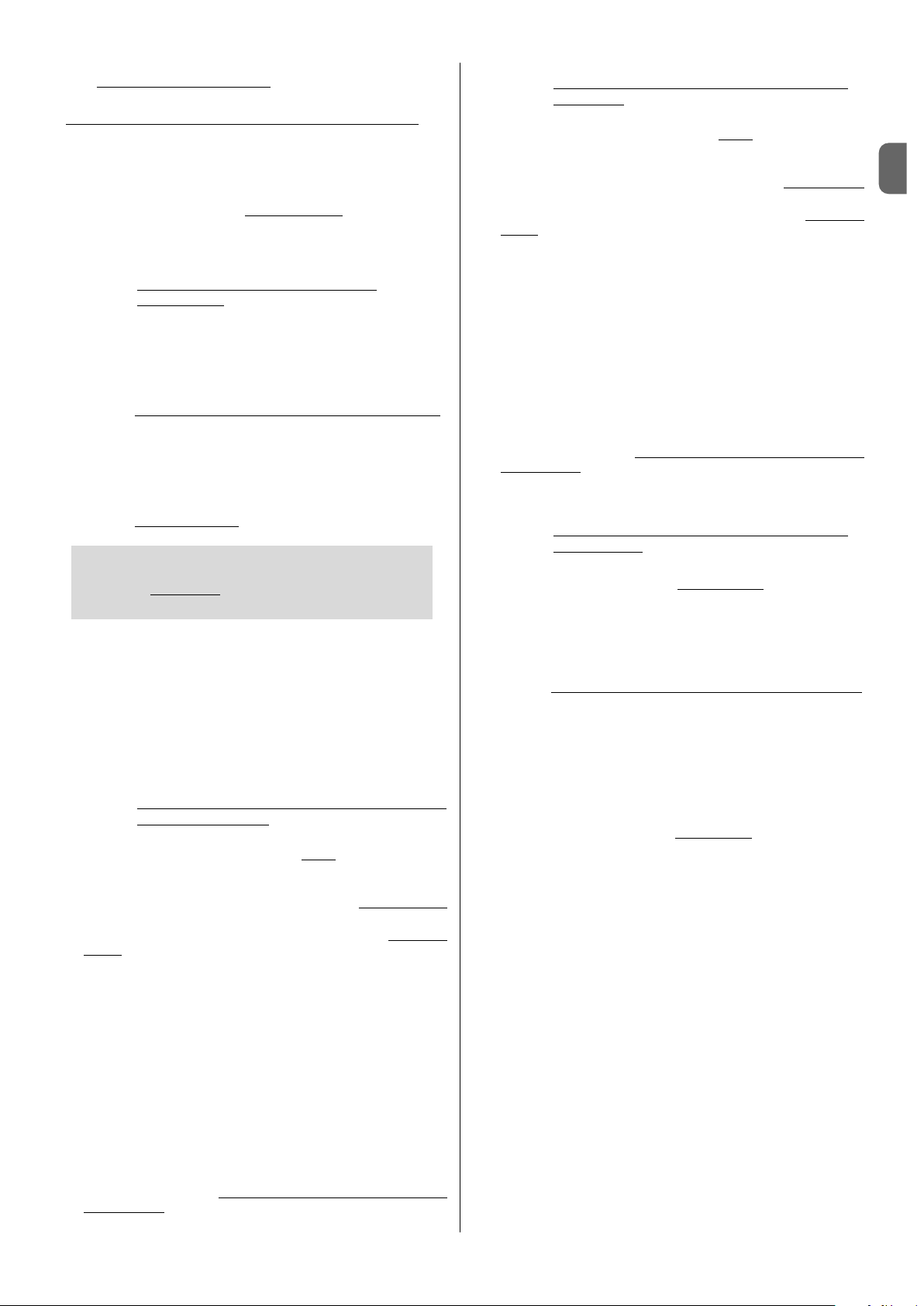
Base coefficient (Cb) for
calculating the maximum possible
number of manoeuvre cycles
per day
Months of year
GRAPH B - For countries 45° SOUTH of the Equator
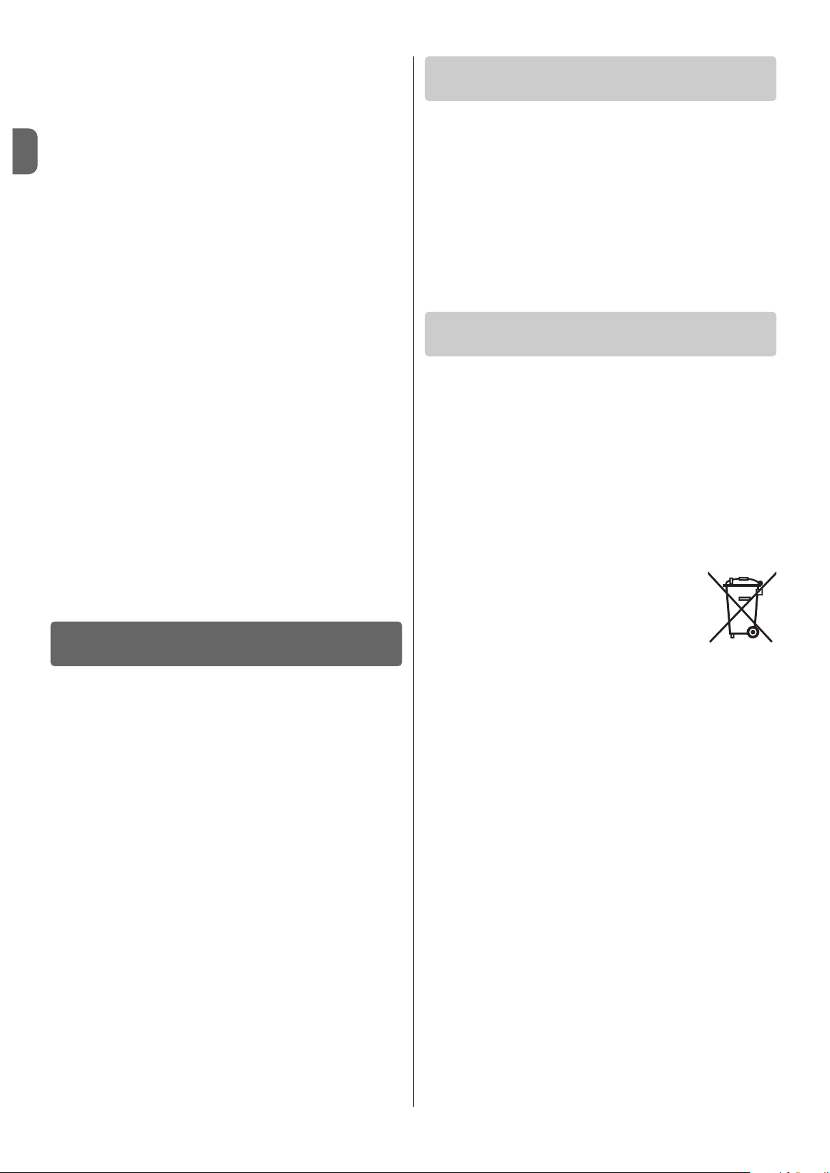
Base coefficient (Cb) for
calculating the maximum possible
number of manoeuvre cycles
per day
Months of year
GRAPH C - For countries on the Equator
Fig. A
mer temperatures, which accelerate part ageing. Normally the battery
average lifetime is approx. 4-5 years; this also depends on the intensity of
automation use.
SYA1 battery charger
Refer to the specific chapter in device instruction manual.
3 – System application limits
VERY IMPORTANT:
-When the automation is powered by the “Solemyo” system, it must
never be connected or powered simultaneously by the electrical
mains.
-The devices SYP and SYA1, which supply energy to PSY24, are alternatives and cannot be used simultaneously.
• for photovoltaic power supply (with SYP)
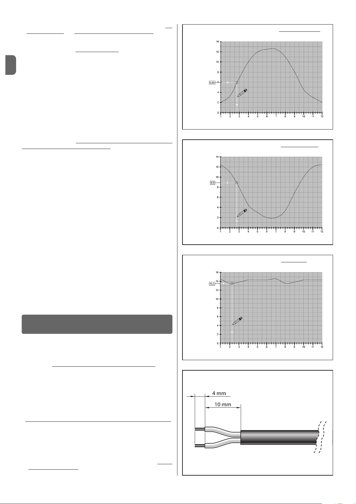
Graphs A, B and C indicate the solar power available, on the basis of the
location’s latitude, at all times of the calendar year, with the automation powered exclusively using PSY24 and SYP devices. The graph curve is generated taking into account the quantity of daylight recorded at a specific latitude
within a year.
To ob t ai n t h e m a xi m um po s si b le n um b er of c yc l es p er da y, pr o ce e d a s f o llows:
01. On graph A, B or C (depending on the latitude of your system) identify
the period of the year concerned, then locate value “Cb” on the vertical
axis, corresponding to this period, as shown in the example in the
graph.
02. Then use value “Cb” to make the calculations as stated in the sheet in
the product pack.
Warning – During the day, if the photovoltaic panel remains in the shade
for a certain period of the day (in particular from 10 am to 2 pm) the maximum possible number of operating cycles decreases in proportion to the
hours without panel exposure to sunlight.
Warning – To in cr ea se t he m ax im um p os si bl e nu mb er o f cy cl es p er d ay,
automation consumption must be reduced. For this reason, the “Standby”
function must be programmed on the automation control units, setting the
most efficient level (refer to the automation instruction manual).
• for mains power supply (with SYA1)
The PSY24 battery must be recharged via the mains in a protected environment, previously detaching PSY24 from the SYP solar panel and the
automation.

4 – Component assembly and connections
STEP 1
– SYP Optimal photovoltaic panel positioning
As a general rule, the panel must be positioned so that it can be constantly
illuminated by sunlight during the day and throughout the year. This means
that its horizontal position and vertical angle must be calculated precisely on
the basis of the location where it is to be installed.
Therefore, after performing the checks specified in chapter 2, and considering the various options for panel installation as shown in fig. 6, proceed as
follows:
• Ensure the correct position of the panel on the horizontal plane
as fol-
lows:
a) In the installation site, determine the cardinal points NORTH and SOUTH,
with the aid of a compass or a geographical map of the location.
b) Then position the panel in the direction NORTH or SOUTH, according to
the following:
– if the installation site is in a country North of the equator (United
States; Europe; Russia; etc.) the panel must be positioned exactly
SOUTH;
– if the installation site is in a country South of the equator (Latin Amer-
ica; Australia; Indonesia, etc.) the panel must be positioned exactly
NORTH.
For further information, refer to fig. 4.
• Ensure the correct position of the panel on the vertical plane
as fol-
lows:
Considering the fact that maximum efficiency of the panel is also required in
the winter period, i.e. when the daily hours of sunlight are fewer than in the
Summer, the panel should be positioned at an angle that receives the sun
rays at right angles (frontal) to the sensitive surface.
This angle corresponds to the latitude of the location
and can be read on any
commercial geographical map. For example, Madrid has a latitude of 40°;
Venice 45°; or London approx 50° etc. For further information , refer to fig. 5.
STEP 2 –Fixing the SYP photovoltaic panel in the selected site
After establishing the precise position of the panel, fit all components of the
support bracket according to the instructions in fig. 3.
Then fix the panel bracket to the selected surface as shown in fig. 6.
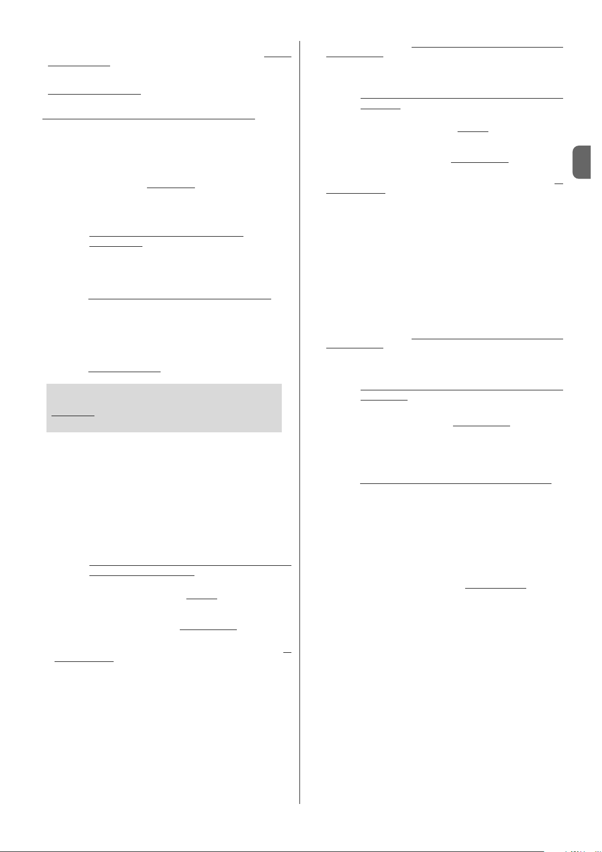
STEP 3 – Fixing the PSY24 battery in the selected site
After performing the checks specified in chapter 2 establishing the precise
position for the battery, fix the latter onto the selected surface as shown in
fig. 13. Note – For fixture, use two screws on the underside, only if the battery is to be secured in a fixed position and not removable.
STEP 4 – Cable routing
After fixing the panel and battery, route the panel cable through the tube or
protection ducting through to the battery.
With reference to the instruction manual of the automation to be powered,
remove the control unit protection cover. Then pass the end of the power
cable (with wires stripped) through the automation (where the other cables
are routed) and through the dedicated cable clamp. Then route the cable
through the protection ducting (if present) through to the battery.
Caution! – Do not connect the power cable to the control unit; leave access
to the control unit open and leave the cable clamp loose.
STEP 5 – Assembly of “ L” socket on the SYP photovoltaic
pa nel cable
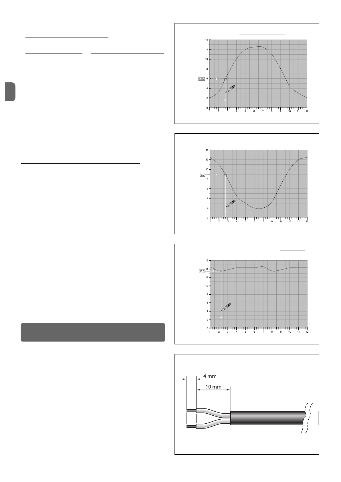
If the cable is too long, it can be shortened, taking care to strip the wires so
that their length is equa
l to the values specified in the fig. A (ca u tion! – differ-
ent lengths may impair subsequent assembly of the socket).
Then proceed with assembly of the GREY
“L” type socket on the end of the
panel cable, as follows:
01. Insert the various elements of the socket on the cable, taking care to
observe the sequence as shown in fig. 7;
IMPORTANT! – If the power cable in the pack is used out-
doors, it must be entirely
protected with special ducting suit-
able for the protection of electric cables.
CAUTION! – Do not modify the electric jumper on the connector (fig. 8).
02. Using a slotted screwdriver, attach the blue wire to terminal n° 1 on
the connector and brown wire to the earthing terminal (4) (fig. 9):
Note – The reference numbers and symbols are printed on the connector below the terminals and on the opposite side.
03. After fixing the two wires, insert the connector in its casing (fig. 10).
Important – The correct position of the connector is that with the
earthing symbol in the lower position (see fig. 10);
04. Then pull the cable outwards from the socket and insert the seal and
washer (fig. 11-a-b). Lastly, tighten the cable clamp (fig. 11-c) using a
wrench, to guarantee completely sealed closure
.
05. After assembling the socket, position the seal supplied on the connection side (fig. 12).
STEP 6 – Assembly of “ L” socket on the power cable
If the cable is too long, it can be shortened, taking care to strip the wires so
that their length is equal to the values specified in the fig. A (Caution! – dif-
ferent lengths may impair subsequent assembly of the socket).
Then proceed with assembly of the BLACK
“L” type socket on the end of
the power cable, as follows:
01. Insert the various elements of the socket on the cable, taking care to
observe the sequence as shown in fig. 7;
CAUTION! – Do not modify the electric jumper on the connector (fig. 8).
02. Using a slotted screwdriver, attach the blue wire to terminal n° 1 on
the connector and the brown wire to the earthing terminal (4) (fig. 9):
Note – The reference numbers and symbols are printed on the connector below the terminals and on the opposite side.
03. After fixing the two wires, insert the connector in its casing (fig. 10).
Important – The correct position of the connector is that with the
earthing symbol in the lower position (see fig. 10);
04. Then pull the cable outwards from the socket and insert the seal and
washer (fig. 11-a-b). Lastly, tighten the cable clamp (fig. 11-c) using a
wrench, to guarantee a completely sealed closure
.
05. After assembling the socket, position the seal supplied on the connection side (fig. 12).
STEP 7 – Connecting the SYP photovoltaic panel to the
PSY24 battery
To c o nn e ct th e p a ne l t o t h e b at t er y, p r oc e ed as fo l lo w s:
01. Connect the GREY
“L” type socket to the “IN” connector on the bat-
tery (fig. 14);
02. To s e le c t th e m o st su i ta b le c o nn e ct i on co n fi g ur a ti o n fo r t h e c on n ec t io n
of all system devices, refer to the example shown in fig. 15. Note – If
frequent disconnection of the battery plug is envisaged, use the screw
in fig. 16-a. Otherwise use the screw in fig. 16-b.
STEP 8 – Connecting the PSY24 battery to the automation
CAUTION! – For safety reasons, the operations described in Step
8 must be performed exclusively by a skilled and qualified technician.
To c o nn e ct th e b a tt e ry to th e a u to m at i on , p ro c ee d a s f o ll o ws :
01. Access the control unit of the automation and insert the power cable
connector in the buffer battery socket on the control unit. To lo ca te t hi s
socket, refer to the instruction manual of the automation to be powered.
02. Connect the BLACK
“L” type socket to the OUT connector on the bat-
tery (fig. 17);
03. Fix the socket by means of the safety screws supplied, with reference
to fig. 18. Note – If frequent disconnection of the connector from the
battery is envisaged, use the screw in fig. 16-a. Otherwise use the
screw in fig. 16-b.
SYSTEM INSTALLATION
English – 3
EN

EN
4 – English
• The automation control unit does not turn on and the PSY24 battery
does not supply any signal.
This may depend on incorrect connections or electrical wiring not fully inserted; otherwise the PSY24 battery may be completely discharged, without
sufficient energy to indicate the battery low status.
In this case, follow the quick recharging procedure, using the SYA1 battery
charger, or wait until the SYP photovoltaic panel, correctly connected, starts
to recharge the PSY24 battery.
• The PSY24 battery tends to discharge too quickly.
This may be due to excessive ageing of the battery, in which case replacement is recommended; otherwise it may be due to excessively intensive use
of the automation, over the application limits envisaged in this manual, found
in Chapter 3.
• The PSY24 battery no longer recharges.
This may be due to a malfunction of the SYP photovoltaic panel caused by
incorrect installation, incorrect cable connections, or malfunction of the
PSY24 battery.
In general, these devices do not require special maintenance; however, regular checks over time will ensure system efficiency.
Therefore, to ensure correct maintenance, check every 6 months that the
SYP photovoltaic panel has not accumulated dirt (leaves, sand, etc.) as this
may reduce efficiency.
Also check whether PSY24 battery replacement is required, as the ageing
process reduces autonomy over time.
CAUTION – The PSY24 battery must be replaced exclusively by skilled
and qualified personnel.
System device disposal
These devices are an integral part of the automation and therefore
must be disposed together with the latter.
As in installation, also at the end of lifetime of these devices, the disassembly and scrapping operations must be performed by qualified personnel.
These devices comprise various types of materials: some of which can be
recycled while others must be scrapped. Seek information on the recycling
and disposal systems envisaged by the local regulations in your area for the
relative device category.
Caution! – some parts of these devices may contain polluting or hazardous
substances which, if disposed of into the environment, may cause serious
damage to the environment or physical health.
As indicated by the symbol alongside, disposal of these
devices in domestic waste is strictly prohibited. Separate
the waste into categories for disposal, according to the
methods envisaged by current legislation in your area, or
return the devices to the retailer when purchasing new
equivalent versions.
Caution! – local legislation may envisage serious fines in the event of abusive
disposal of these devices.
PSY24 Battery disposal
Caution! – The battery contains pollutant substances; after removing, never
dispose of as standard waste. Dispose of or recycle according to current
local standards.
WHAT TO DO IF...
(troubleshooting guide)
PERIODIC MAINTENANCE
OPERATIONS
DISPOSAL
5 – General notes on system use
In general, when the PSY24 battery is not sufficiently charged, the energy
reserve will run out in a few days. For this reason, after installation and connecting the product to the automation, the system may not be operative
immediately (this depends on the fact that the battery may be discharged
due to the natural process of discharging over time, even when stored).
The PSY24 battery enables a finite number of automation manoeuvre cycles
(refer to the information sheet in the pack). Therefore, if not constantly
recharged using SYP or occasionally by means of SYA1, the battery low sig-
nal may be activated, with sequential flashing of the Led and a series of
beeps (this signal may be temporary or permanent).
In particular, when powered by SYP, recharging may be influenced by atmospheric conditions, or intense use of the automation (when the maximum
admissible number of manoeuvre cycles is exceeded). When this occurs,
PSY24 may indicate the battery low status.
PSY24 charging can be restored in one of the following ways:
A) -Bylimiting use of the automation until lighting conditions improve to
enable the battery to recharge naturally, via the connection to the SYP
photovoltaic panel.
To ac celerate t he re c ha rg ing p ro ce ss, d is co nnect P SY 24 f ro m the
automation control unit and wait for a few days to enable the SYP photovoltaic panel to store sufficient solar energy to recharge the PSY24
battery.
B) -Disconnect the PSY24 battery from the automation control unit and the
SYP solar panel (if present). Then recharge PSY24 using the SYA1 battery charger connected to the mains in a protected environment.
When the PSY24 battery is recharging (via the SYP photovoltaic panel or
SYA1 battery charger) the red led emits 2 short flashes every 5 seconds.
Therefore check that this signal is present, also after installation, when the
panel is exposed to the sunlight.
The “battery low” warning signal is cleared when the system reaches sufficient electrical autonomy to enable automation operation.
If the automation is not used for extended periods, disconnect the automation and photovoltaic panel connectors from the battery, and store the latter
in a cool and dry location.

IT
Italiano – 1
ITALIANO
AVVERTENZE E PRECAUZIONI GENERALI
PER LA SICUREZZA
La progettazione, la fabbricazione dei dispositivi che compongono il
sistema Solemyo e le informazioni contenute nel presente manuale
rispettano pienamente le normative vigenti sulla sicurezza. Ciò nonostante, un’installazione errata può causare gravi ferite alle persone che
eseguono il lavoro e a quelle che useranno l’impianto. Per questo motivo, durante l’installazione, è importante seguire attentamente tutte le
istruzioni riportate in questo manuale.
Non procedere con l’installazione se si hanno dubbi di qualunque natura e
richiedere eventuali chiarimenti al Servizio Assistenza Nice.
OPERARE IN CONDIZIONI DI SICUREZZA!
Attenzione – Per la sicurezza delle persone è importante rispettare queste istruzioni.
Attenzione – Istruzioni importanti per la sicurezza: quindi, conservare queste istruzioni.
Rispettare le seguenti av vertenze:
–effettuare esclusivamente i collegamenti elettrici previsti nel presente
manuale: un’errata esecuzione dei collegamenti potrebbe causare
gravi danni al sistema.
–se il cavo di alimentazione presente nell’imballo è utilizzato in am -
biente esterno, è obbligatorio proteggerlo interamente
con un tubo
specifico per la protezione dei cavi elettrici.
–non toccare con oggetti metallici le parti metalliche delle prese che
sono sull’involucro dell’accumulatore.
Considerando le situazioni di rischio che possono verificarsi durante le
fasi d’installazione e di uso del sistema, è necessario installare i dispositivi presenti nella confezione osservando le seguenti avvertenze:
–non eseguire modifiche su nessuna parte dei dispositivi, se non quelle pre-
viste nel presente manuale. Operazioni non permesse possono solo causare malfunzionamenti. Il costruttore declina ogni responsabilità per danni
derivanti da dispositivi modificati arbitrariamente.
–non mettere i dispositivi vicino a fonti di calore né esporli a fiamme libere.
Ta li azioni po ss o no danneggiarl i e d e ssere ca usa di ma lf unzionam e nt i,
incendio o situazioni di pericolo.
–evitare che i dispositivi possano venire immersi in acqua o in altre sostanze
liquide. Durante l'installazione evitare che dei liquidi possano penetrare
all'interno dei dispositivi.
–il materiale dell’imballaggio dei dispositivi deve essere smaltito nel pieno
rispetto della normativa presente a livello locale.
Attenzione! – Conservare con cura questo manuale per facilitare eventuali
interventi futuri di manutenzione o di smaltimento dei dispositivi.
1 – Descrizione e destinazione d’uso
SOLEMYO è un sistema autonomo di alimentazione destinato agli automatismi Nice per cancelli e portoni da garage (la lista degli automatismi predisposti è riportata nel foglio contenuto nella confezione ed è consultabile anche
nel sito www.niceforyou.com).
Ogni altro uso è da considerarsi improprio! Il costruttore non risponde
dei danni risultanti da un uso improprio dei vari dispositivi del sistema,
diverso da quanto previsto nel presente manuale.
Il sistema Solemyo è particolarmente indicato per alimentare automazioni
collocate lontano dalla rete elettrica fissa.
È composto da 3 dispositivi base, la cui combinazione permette configurazioni diverse, in grado di immagazzinare energia solare oppure energia dalla
rete elettrica, per utilizzarla quando è richiesta dall’automazione sulla quale è
installato il sistema.
I vari dispositivi del sistema sono disponibili nelle seguenti confezioni:
- PSY24: è il cuore del sistema. Il dispositivo può immagazinare l’energia
elettrica prodotta da SYP durante le ore di sole, rendendola disponibile in
ogni ora del giorno, compresi i giorni con cattivo tempo. Lo stesso dispositivo può immagazinare anche l’energia elettrica dalla rete fissa, attraverso
SYA1. La confezione contiene l’accumulatore PSY24, i cavi, i connettori per
i collegamenti all'automazione, la minuteria per il fissaggio e il presente
manuale;
- SYP: è un dispositivo in grado di convertire la luce solare direttamente in
energia elettrica. La confezione contiene un pannello fotovoltaico SYP per la
ricarica di PSY24, e la minuteria per il fissaggio;
- SYKCE: è un kit completo per l’alimentazione autonoma fotovoltaica. La
confezione contiene i dispositivi PSY24, SYP, i cavi, i connettori per i collegamenti all'automazione, la minuteria per il fissaggio e il presente manuale;
- SYA1: è un dispositivo che consente la ricarica periodica o di emergenza di
PSY24, da rete elettrica fissa e in ambiente protetto. La confezione contiene
un carica batterie SYA1.
2 – Verifiche preliminari all’installazione
Per stabilire l’idoneità del sistema rispetto alle caratteristiche dell’automatismo da alimentare, effettuare le verifiche descritte in questo capitolo e controllare la loro conformità anche in base ai dati tecnici riportati nel capitolo
“Caratteristiche tecniche”.
In prossimità dell’automatismo da alimentare, individuare il punto più adatto
per installare il pannello fotovoltaico e quello più adatto per installare l’accumulatore, tenendo in considerazione i seguenti vincoli:
a)i limiti d’impiego descritti in questo capitolo;
b)la lunghezza massima del cavo di alimentazione (3 m) e di quello del pan-
nello fotovoltaico (3 m);
c)lo spazio disponibile in prossimità dell’automatismo da alimentare.
Inoltre, effettuare le seguenti verifiche:
d)verificare che le superficie scelte per fissare i due dispositivi siano di mate-
riale solido e possano garantire un fissaggio stabile.
e)verificare che ciascun dispositivo da installare sia collocato in una posizio-
ne protetta da urti accidentali.
f)in particolare, per ciascun dispositivo, verificare quanto segue:
SYP pannello fotovoltaico
– verificare che il luogo prescelto per l’installazione del pannello garantisca
il 100% dell’insolazione diretta (pieno sole), in qualsiasi giornata dell’anno.
–verificare che il punto prescelto per l’installazione del pannello sia lontano da vegetazione, muri o altre situazioni che possano creare zone d’ombra, anche parziali
, sulla sua superficie sensibile. Attenzione! – questa
superficie deve essere illuminata dai raggi solari in modo diretto e in
ogni punto; un’ombra parziale, anche se di piccole dimensioni (dovuta, ad esempio, a una foglia o ad altro), riduce sensibilmente la capacità energetica del pannello.
–verificare la possibilità di orientare
e inclinare correttamente il pannello,
facendo riferimento alle istruzioni riportate nel capitolo 4.
PSY24 accumulatore
Per ottenere dall’accumulatore un’efficienza ottimale e una lunga durata è
preferibile installare quest’ultimo, in un punto – in prossimità dell’automatismo da alimentare – che possa proteggerlo dalle alte temperature estive e
dalle basse temperature invernali.
Infatti, il rendimento della carica dell’accumulatore dipende dalla tem-
peratura dell’ambiente in cui questo è installato: l’efficienza ottimale si
ottiene alle medie temperature, mentre si riduce sensibilmente alle basse
temperature.
CONOSCENZA DEL SISTEMA E
PREPARAZIONE ALL’INSTALLAZIONE
Istruzioni originali
4 - Assemblaggio e collegamento dei vari
componenti
PASSO 1 – Posizione ottimale del pannello fotovoltaico SYP
In generale, il pannello deve essere posizionato in modo che possa essere
illuminato costantemente dal sole, in tutto l’arco della giornata e in ogni
periodo dell’anno. Questo lo si ottiene orientando scrupolosamente il pannello, sia sul piano orizzontale sia sul piano verticale, calcolando queste posizioni in funzione del luogo in cui il pannello è installato.
Quindi, dopo aver effettuato le verifiche riportate nel capitolo 2 e aver considerato le varie possibilità di installazione del pannello riportate in fig. 6, effettuare le seguenti operazioni:
• Definire il corretto orientamento del pannello sul piano orizzontale
,
procedendo nel modo seguente:
a) Sul luogo dell’installazione, individuare i punti cardinali del NORD e del
SUD, aiutandosi con una bussola o con una cartina geografica del luogo.
b) Infine, orientare il pannello in direzione NORD o SUD, in base alle seguen-
ti valutazioni:
– se il luogo dell’installazione si trova in un Paese a Nord dell’equatore
(Stati Uniti; Europa; Russia; ecc.) il pannello deve essere orientato esatta
mente in direzione SUD;
–se il luogo dell’installazione si trova in un Paese a Sud dell’equatore
INSTALLAZIONE DEL SISTEMA
2 – Italiano
IT
Coefficiente base (Cb) per
calcolare il numero massimo
possibile di cicli di manovre
al giorno
Mesi dell’anno
GRAFICO A - Per i Paesi che sono a 45° NORD dell’Equatore
Coefficiente base (Cb) per
calcolare il numero massimo
possibile di cicli di manovre
al giorno
Mesi dell’anno
GRAFICO B - Per i Paesi che sono a 45° SUD dell’Equatore
Coefficiente base (Cb) per
calcolare il numero massimo
possibile di cicli di manovre
al giorno
Mesi dell’anno
GRAFICO C - Per i Paesi che sono all’Equatore
Invece, la longevità dell’accumulatore è influenzata soprattutto dalle alte
temperature estive che accellerano l’invecchiamento delle parti. Normalmente la vita media delle batterie è di circa 4-5 anni; questa dipende
anche dall’intensità con la quale si usa l’automazione.
SYA1 carica batteria
Fare riferimento al capitolo specifico presente nel manuale istruzioni del
dispositivo.
3 – Limiti d’impiego del sistema
MOLTO IMPORTANTE
-Quando l’automazione è alimentata dal sistema “Solemyo”, non deve
essere collegata e non deve essere alimentata contemporaneamente anche dalla rete elettrica.
-I dispositivi SYP e SYA1, che forniscono energia al dispositivo PSY24,
sono alternativi tra loro e non possono essere impiegati contemporaneamente.
• per l’alimentazione fotovoltaica (con SYP)
I grafici A, B e C indicano l’energia solare disponibile, in base alla latitudine
del luogo, in ogni momento dell’anno solare, con l’automazione alimentata
esclusivamente tramite la coppia di dispositivi PSY24 e SYP. La curva di ogni
grafico è generata prendendo in considerazione la quantità di luce giornaliera registrata a una determinata latitudine nell’arco di un anno.
Per ottenere il numero massimo possibile di cicli al giorno, procedere nel
modo seguente.
01. Individuare sul grafico A, B o C (secondo la latitudine in cui si trova il
vostro impianto) il periodo dell’anno che interessa; quindi trovare sull’asse verticale il valore “Cb” che corrisponde a questo periodo, ope-
rando come indicato nell’esempio riportato nel grafico.
02. Infine, utilizzare questo valore “Cb” per eseguire i calcoli riportati nel
foglio contenuto nella confezione.
Attenzione – Se durante la giornata il pannello fotovoltaico rimane in ombra
per una parte del tempo (in particolare, dalle ore 10.00 alle ore 14.00), il
numero massimo possibile di cicli di manovre si riduce in funzione delle ore
mancanti di esposizione del pannello al sole.
Attenzione – Per aumentare il numero massimo possibile di cicli al giorno, è
fondamentale ridurre i consumi dell’automazione. Per questo motivo, sulle
centrali di comando delle automazioni è importante programmare la funzione
“Stand-by” impostando il livello più efficace (fare riferimento al manuale dell’automazione).
• per l’alimentazione da rete elettrica fissa (con SYA1)
La ricarica dell’accumulatore PSY24 da rete elettrica fissa va fatta in ambiente protetto, scollegando preventivamente PSY24 dal pannello solare SYP e
dall’automazione.
Fig. A
di quest’ultima la guarnizione in dotazione (fig. 12).
PASSO 6 – Assemblaggio della presa “a pipetta” sul cavo di ali-
mentazione
Se il cavo è eccessivamente lungo, si può accorciare facendo attenzione a
spelare i fili in modo che la loro lunghezza risulti uguale
a quelle riportate nel-
la fig. A (attenzione! – lunghezze diverse pregiudicano il successivo assem-
blaggio della presa).
Quindi, procedere ad assemblare la presa “a pipetta” in colore NERO
all’estremità del cavo di alimentazione, nel modo se guente:
01. Infilare sul cavo i vari elementi che compongono la presa, rispettando
l’ordine mostrato in fig. 7;
ATTE NZION E! –Non modificare il ponticello elettrico presente sul connettore (fig. 8).
02. Utilizzando un cacciavite a taglio, fissare sul connettore il filo Blu al morsetto n° 1 e il filo Marrone al morsetto della presa a terra (4) (fig. 9):
Nota –I numeri e i simboli di riferimento sono stampati sul connettore,
in basso rispetto ai morsetti e sulla faccia opposta.
03. Dopo aver fissato i due fili, procedere ad inserire il connettore nella sua
protezione (fig. 10).
Importante – La posizione corretta del connettore è quella con il
simbolo della presa a terra posizionato verso il basso (vedere la
fig. 10);
04. Quindi, tirare il cavo verso l’esterno della presa e inserire in questa la
guarnizione e la rondella (fig. 11-a-b). Infine, avvitare il pressacavo (fig.
11-c) usando una chiave, in modo da ottenere una chiusura completa
-
mente ermetica.
05. Dopo aver assemblato la presa, posizionare sulla faccia di connessione
di quest’ultima la guarnizione in dotazione (fig. 12).
PASSO 7 –Collegamento del pannello fotovoltaico SYP all’accu-
mulatore PSY24
Per collegare il pannello all’accumulatore, procedere nel modo seguente:
01. Connettere la presa “a pipetta” in colore GRIGIO
alla presa “IN” sul-
l’accumulatore (fig. 14);
02. Fissare la presa con la vite di sicurezza in dotazione, facendo riferimento alla fig. 15. Nota –Se si prevede di scollegare spesso la presa dal-
l’accumulatore, utilizzare la vite di fig. 16-a. In caso contrario, utilizzare
la vite di fig. 16-b.
PASSO 8 –Collegamento dell’accumulatore PSY24 all’automatismo
ATTE NZION E! – P er q uest ioni di s icure zza, le opera zioni des critte
in questo Passo 8 devono essere eseguite esclusivamente da un
tecnico qualificato e competente.
Per collegare l’accumulatore all’automatismo, procedere nel modo seguente:
01. Accedere alla Centrale di comando dell’automatismo ed inserire il connettore del cavo di alimentazione nella presa destinata alla batteria tampone, presente sulla Centrale. Per individuare questa presa, fare riferi-
mento al manuale istruzioni dell’automatismo da alimentare.
02. Connettere la presa “a pipetta” in colore NERO
alla presa “OUT” sul-
l’accumulatore (fig. 17);
03. Fissare la presa con la vite di sicurezza in dotazione, facendo riferimento alla fig. 18. Nota –Se si prevede di scollegare spesso la presa dal-
l’accumulatore, utilizzare la vite di fig. 16-a. In caso contrario, utilizzare
la vite di fig. 16-b.
(America Latina; Australia; Indonesia; ecc.) il pannello deve essere orientato esattamente in direzione NORD
.
Per maggiore chiarezza, fare riferimento alla fig. 4.
• Definire il corretto orientamento del pannello sul piano verticale
, pro-
cedendo nel modo seguente:
Considerando che è preferibile ottenere la massima efficienza del pannello nel
periodo invernale, quando cioè le ore giornaliere di luce solare sono minori
che nell’estate, occorre orientare il pannello con un’inclinazione tale da ricevere i raggi del sole perpendicolari (frontali) alla sua superficie sensibile.
Questa inclinazione corrisponde alla latitudine del luogo
e può essere rilevata in qualsiasi cartina geografica: ad esempio, Madrid ha latitudine di 40°;
Venezia di 45°; Londra di circa 50° ecc. Per maggiore chiarezza, fare riferimento alla fig. 5.
PASSO 2 –Fissaggio del pannello fotovoltaico SYP nel
punto prescelto
Dopo aver stabilito con esattezza la posizione del pannello, assemblare
tutti i componenti della sua staffa di supporto, seguendo le istruzioni riportate in fig. 3.
Infine, fissare la staffa del pannello sulla superficie prescelta, come mostrato in fig. 6.
PASSO 3 –Fissaggio dell’accumulatore PSY24 nel punto prescelto
Dopo aver effettuato le verifiche riportate nel capitolo 2 e stabilito con esattezza la posizione in cui collocare l’accumulatore, fissare quest’ultimo sulla
superficie prescelta, come mostrato in fig. 13. Nota – Per il fissaggio, utiliz-
zare le 2 viti posizionate in basso soltanto se si desidera ancorare l’accumulatore in modo fisso e non asportabile.
PASSO 4 – Passaggio dei cavi
Dopo aver fissato il pannello e l’accumulatore, passare il cavo del pannello
attraverso il tubo o la canalina di protezione, portandolo fino all’accumulatore.
Facendo riferimento al manuale istruzioni dell’automatismo da alimentare,
rimuovere il coperchio di protezione della Centrale di comando. Quindi, passare attraverso l’automatismo (dove passano gli altri cavi) l’estremità del
cavo di alimentazione con i fili spelati e farlo uscire dall’automatismo attraverso il passacavo dedicato. Infine, passare il cavo attraverso l’eventuale canalina di protezione portandolo fino all’accumulatore.
Attenzione! –Non collegare il cavo di alimentazione alla Centrale; lasciare
aperto l’accesso alla Centrale e lasciare allentato il passacavo.
PASSO 5 – Assemblaggio della presa “a pipetta” sul cavo del pan-
nello fotovoltaico SYP
Se il cavo è eccessivamente lungo, si può accorciare facendo attenzione a
spelare i fili in modo che la loro lunghezza risulti uguale
a quelle riportate nel-
la fig. A (attenzione! – lunghezze diverse pregiudicano il successivo assem-
blaggio della presa).
Quindi, procedere ad assemblare la presa “a pipetta” in colore GRIGIO
all’estremità del cavo del pannello, nel modo seguente:
01. Infilare sul cavo i vari elementi che compongono la presa, rispettando
l’ordine mostrato in fig. 7;
ATTE NZION E! –Non modificare il ponticello elettrico presente sul connettore (fig. 8).
02. Utilizzando un cacciavite a taglio, fissare sul connettore il filo Blu al
morsetto n° 1 e il filo Marrone al morsetto della presa a terra (4)
(fig. 9):
Nota –I numeri e i simboli di riferimento sono stampati sul connettore,
in basso rispetto ai morsetti e sulla faccia opposta.
03. Dopo aver fissato i due fili, procedere ad inserire il connettore nella sua
protezione (fig. 10).
Importante – La posizione corretta del connettore è quella con il
simbolo della presa a terra posizionato verso il basso (vedere la
fig. 10);
04. Quindi, tirare il cavo verso l’esterno della presa e inserire in questa la
guarnizione e la rondella (fig. 11-a-b). Infine, avvitare il pressacavo (fig.
11-c) usando una chiave, in modo da ottenere una chiusura completa
-
mente ermetica.
05. Dopo aver assemblato la presa, posizionare sulla faccia di connessione
IMPORTANTE! –Se il cavo di alimentazione presente nel-
l’imballo è utilizzato in ambiente esterno, è obbligatorio
proteggerlo interamente
con un tubo specifico per la prote-
zione dei cavi elettrici.
Italiano – 3
IT
IT
4 – Italiano
5 – Note generali sull’uso del sistema
In generale, quando l’accumulatore PSY24 non è adeguatamente ricaricato,
esaurisce la sua riserva di energia entro pochi giorni. Per questo motivo, al
termine dell’installazione, dopo aver collegato il sistema all’automatismo,
l’impianto potrebbe non essere operativo subito (l’accumulatore potrebbe
essere scarico a causa del normale processo di autoscarica che avviene nel
tempo, anche quando il prodotto è a magazzino).
L’ ac cu mu la to re PS Y2 4 c on se nt e al l’ au to m az io ne un n ume ro fi ni to di ci cl i d i
manovre (fare riferimento al foglio contenuto nella confezione). Pertanto, se
non è ricaricato costantemente con SYP o saltuariamente con SYA1 può
segnalare lo stato di batteria scarica con dei lampeggi ciclici del Led e dei
beep acustici (la segnalazione può essere temporanea o permanente).
In particolare, quando è alimentato con SYP la ricarica può essere influenzata sia dalle condizioni atmosferiche, sia dall’uso intenso dell’automazione
(quando si supera il numero massimo possibile dei cicli di manovre). Quando
ciò avviene, PSY24 potrebbe segnalare lo stato di batteria scarica.
la ricarica di PSY24 può essere ripristinata con una delle seguenti modalità:
A) -Limitare l’uso dell’automazione in attesa che migliorino le condizioni di
insolazione, permettendo così la ricarica dell’accumulatore in modo
naturale, sfruttando il collegamento presente al pannello fotovoltaico
SYP.
Per accelerare il processo di ricarica, scollegare PSY24 dalla centrale di
comando dell’automazione e attendere qualche giorno affinchè il pannello fotovoltaico SYP riceva sufficiente energia solare per ricaricare
l’accumulatore PSY24.
B) -Scollegare l’accumulatore PSY24 dalla Centrale di comando dell’auto-
mazione e dal pannello solare SYP (se presente). Quindi eseguire la
ricarica di PSY24 utilizzando in ambiente protetto il carica batteria da
rete fissa SYA1.
Quando l’accumulatore PSY24 è in ricarica (da pannello fotovoltaico SYP o
da carica batteria SYA1), il Led rosso emette 2 brevi lampeggi ogni 5 secondi. Verificare che questa segnalazione sia presente anche dopo l’installazione, quando il pannello è illuminato dal sole.
La segnalazione di batteria scarica termina quando il sistema raggiunge una
sufficiente autonomia elettrica per far funzionare l’automazione.
Se l’automazione non viene usata per lunghi periodi si consiglia di scollegare
dall’accumulatore i connettori dell’automatismo e del pannello fotovoltaico, e
di custodire l’accumulatore in un luogo fresco e asciutto.
• La Centrale di comando dell’automatismo non si accende e l’accunulatore PSY24 non da nessuna segnalazione.
Questo potrebbe dipendere dai collegamenti non corretti o dai fili elettrici non
perfettamente inseriti; oppure l’accunulatore PSY24 potrebbe essere completamente scarico e non avere l’energia sufficiente per segnalare lo stato di
batteria scarica.
In questo caso è necessario effettuare una ricarica rapida usando il carica
batteria SYA1, oppure attendere che il pannello fotovoltaico SYP, correttamente collegato, cominci a ricaricare l’accumulatore PSY24.
• L’accumulatore PSY24 tende a scaricarsi troppo velocemente.
Questo potrebbe dipendere da un invecchiamento eccessivo dell’accunulatore per cui sarebbe opportuno sostituirlo; oppure la causa potrebbe essere
un uso troppo intensivo dell’automazione, oltre i limiti d’impiego previsti in
questo manuale, nel capitolo 3.
• La accumulatore PSY24 non si ricarica più.
Questo potrebbe dipendere da un malfunzionamento del pannello fotovoltaico SYP, a causa di una sua errata installazione, oppure da un collegamento
errato dei cavi, oppure da un malfunzionamento dell’accumulatore PSY24.
n generale, i dispositivi del sistema non necessitano di manutenzioni particolari; tuttavia, un controllo regolare nel tempo consente di mantenere in efficienza l’impianto.
Quindi, per effettuare una manutenzione corretta, verificare ogni 6 mesi che il
pannello fotovoltaico SYP non abbia accumulato sporcizia (foglie, sabbia,
ecc.): questa potrebbe diminuire l’efficienza.
Inoltre, è necessario verificare se è il caso di sostituire l’accumulatore PSY24
che, per effetto dell’invecchiamento, potrebbe ridurre nel tempo la sua autonomia.
ATTE NZIO NE –L’eventuale sostituzione dell’accumulatore PSY24
deve es sere eseguita esclusivamente da personale qualificato ed
esperto.
COSA FARE SE...
(guida alla risoluzione dei problemi)
INTERVENTI DI
MANUTENZIONE PERIODICA
Smaltimento dei dispositivi del sistema
I presenti dispositivi sono parte integrante dell'automazione, e dunque,
devono essere smaltiti insieme con essa.
Come per le operazioni d'installazione, anche al termine della vita di questi
dispositivi, le operazioni di smantellamento devono essere eseguite da personale qualificato.
Questi dispositivi sono costituiti da vari tipi di materiali: alcuni possono essere riciclati, altri devono essere smaltiti. Informatevi sui sistemi di riciclaggio o
smaltimento previsti dai regolamenti vigenti sul vostro territorio, per la categoria di questi dispositivi.
Attenzione! – alcune parti dei dispositivi possono contenere sostanze inquinanti o pericolose che, se disperse nell’ambiente, possono provocare effetti
dannosi sull'ambiente stesso e sulla salute umana.
Come indicato dal simbolo a lato, è vietato gettare questi
dispositivi nei rifiuti domestici. Eseguire quindi la “raccolta
separata” per lo smaltimento, secondo i metodi previsti dai
regolamenti vigenti sul vostro territorio, oppure riconsegnare i dispositivi al venditore nel momento dell'acquisto di
nuovi dispositivi equivalenti.
Attenzione! – i regolamenti vigenti a livello locale possono prevedere pesanti sanzioni in caso di smaltimento abusivo di questi dispositivi.
Smaltimento dell’accumulatore PSY24
Attenzione! – L’accumulatore contiene sostanze inquinanti e, dopo averlo
rimosso, non deve essere buttato nei rifiuti comuni. Occorre smaltirlo o riciclarlo utilizzando i metodi previsti dalle normative vigenti nel vostro territorio.
SMALTIMENTO

FR
Français – 1
FRANÇAIS
AVERTISSEMENTS ET PRÉCAUTIONS
GÉNÉRALES POUR LA SÉCURITÉ
La conception, la fabrication des dispositifs qui composent le système
Solemyo et les informations contenues dans ce guide respectent pleinement les normes en vigueur en matière de sécurité. Toutefois, une
installation incorrecte peut causer de graves blessures aux personnes
qui effectuent le travail et à celles qui utiliseront l’installation. Pour
cette raison, au cours de l’installation, il est important de suivre attentivement toutes les instructions figurant dans ce guide.
Ne pas effectuer l’installation si le moindre doute persiste et demander les
éclaircissements nécessaires au Service après-vente Nice.
OPÉRER EN CONDITIONS DE SÉCURITÉ !
Attention – Pour la sécurité des personnes, il est important de
respecter ces instructions.
Attention – Instructions importantes pour la sécurité : con server
par conséquent ces instructions.
Respecter les consignes suivantes :
–effectuer exclusivement les connexions électriques prévues dans ce
guide : une exécution erronée des connexions pourrait causer de
graves dommages au système.
–Si le câble d’alimentation présent dans l’emballage est utilisé à l’ex-
térieur, il est obligatoire de le protéger entièrement
avec une gaine
spécifique pour la protection des câbles électriques.
–ne pas toucher avec des objets métalliques les parties métalliques
des prises qui sont sur le boîtier de l’accumulateur.
Compte tenu des situations de risque qui peuvent se vérifier durant les
phases d’installation et d’utilisation du système, il faut installer les dispositifs présents dans l’emballage en respectant les recommandations
qui suivent :
–ne pas effectuer de modifications sur des parties du dispositif quelles
qu’elles soient, en dehors de celles qui sont décrites dans ce guide. Des
opérations non autorisées ne peuvent que provoquer des problèmes de
fonctionnement. Le constructeur décline toute responsabilité pour les
dommages dérivant de dispositifs modifiés arbitrairement.
–ne pas mettre les dispositifs à proximité de fortes sources de chaleur ni les
exposer à des flammes vives ; Ces actions peuvent les endommager et
causer des problèmes de fonctionnement, un incendie ou des situations
de danger.
–éviter que les dispositifs puissent être immergées dans l’eau ou dans d’au-
tres substances liquides. Durant l’installation éviter que les liquides puissent pénétrer à l’intérieur des dispositifs.
–les matériaux de l’emballage des dispositifsdoivent être mis au rebut dans
le plein respect des normes locales en vigueur.
Attention ! – Conserver avec soin cette notice pour faciliter les éventu el les
interventions futures de maintenance ou de mise au rebut des dispositifs.
1 – Description et application
SOLEMYO est un système autonome d’alimentation destiné aux automatismes Nice pour portails et portes de garage (la liste des automatismes
compatibles figure dans le feuillet contenu dans l’emballage et est disponible
également sur le site www.niceforyou.com).
To ut e a utre utilisation d o it ê tre c on si dérée c o mm e i mpro p re ! L e
constructeur ne répond pas des dommages résultant d’une utilisation
impropre des différents dispositifs du système différente de ce qui est
prévu dans cette notice.
Le système Solemyo est particulièrement indiqué pour alimenter des automatismes se trouvant loin de l’alimentation de secteur.
Il est composé de 3 dispositifs de base, dont la combinaison permet des
configurations différentes, en mesure de stocker l’énergie solaire ou l’énergie
du secteur électrique, pour l’utiliser quand l’automatisation sur laquelle le
système est installé en a besoin.
Les différents dispositifs du système sont disponibles dans les conditionnements suivants :
- PSY24: c’est le cœur du système. Le dispositif peut stocker l’énergie électrique produite par SYP durant les heures de soleil en la rendant disponible à
toute heure du jour, y compris par temps couvert. Le même dispositif peut
stocker également l’énergie électrique du secteur, à travers SYA1. L’emballage contient l’accumulateur PSY24, les câbles, les connecteurs pour les
connexions à l’automatisation, les accessoires de fixation et le présent
manuel ;
- SYP: c’est un dispositif en mesure de convertir la lumière solaire directement en énergie électrique. L’emballage contient un panneau photovoltaïque
SYP pour la recharge de PSY24, et les accessoires de fixation ;
- SYKCE: c’est un kit complet pour l’alimentation autonome photovoltaïque.
L’emballage contient les dispositifs PSY24, SYP, les câbles, les connecteurs
pour les connexions à l’automatisation, les accessoires de fixation et le présent manuel ;
- SYA1: c’est un dispositif qui permet la recharge périodique ou de secours
de PSY24, par le secteur électrique et dans un milieu protégé. L’emballage
contient un chargeur de batteries SYA1.
2 – Contrôles avant l’installation
Pour s’assurer que le système est adapté aux caractéristiques de l’automatisme à alimenter, effectuer les vérifications décrites dans ce chapitre et
contrôler leur conformité également avec les données techniques figurant
dans le chapitre « Caractéristiques techniques » :
À proximité de l’automatisme à alimenter, identifier le point le plus ada pté
pour installer le panneau photovoltaïque et le point le plus adapté pour installer l’accumulateur, en tenant compte des contraintes suivantes :
a)les limites d’utilisation décrites dans ce chapitre ;
b)la longueur maximum du câble d’alimentation (3 m) et de celui du pan-
neau photovoltaïque (3 m) ;
c)l’espace disponible près de l’automatisme à alimenter.
De plus, effectuer les vérifications suivantes :
d)vérifier que les surfaces choisies pour fixer les deux dispositifs sont d’un
matériau solide et peuvent garantir une fixation stable.
e)Vérifier que chaque dispositif à installer se trouve dans une position proté-
gée, à l’abri des chocs accidentels.
f)En particulier, pour chaque dispositif, vérifier ce qui suit :
SYP panneau photovoltaïque
– vérifier que l’endroit choisi pour l’installation du panneau garantit 100%
d’ensoleillement direct (plein soleil), tout au long de l’année.
– vérifier que le point choisi pour l’installation du panneau est loin de la
végétation, des murs ou d’autres situations qui peuvent créer des zones
d’ombre, même partielle
, sur sa surface sensible. Attention ! – cette
surface doit être exposée aux rayons solaires de manière directe et
en tout point ; une ombre partielle, même si de petites dimensions
(due, par exemple, à une feuille ou autre), réduit sensiblement la
capacité énergétique du panneau.
– vérifier la possibilité d’orienter
et d’incliner correctement le panneau, en
se référant aux instructions techniques du chapitre 4.
PSY24 accumulateur
Pour assurer une efficacité optimale et une longue durée de l’accumulateur, il est préférable d’installer ce dernier à un endroit – à proximité de
l’automatisme à alimenter – en mesure de le protéger contre les hautes
températures estivales et les basses températures hivernales.
CONNAISSANCE DU SYSTÈME ET
PRÉPARATION À L’INSTALLATION
Instructions originales
4 - Assemblage et connexion des différents
composants
PHASE 1
– Positionnement idéal du panneau photovoltaïque SYP
En général, le panneau doit être positionné de manière à pouvoir être exposé
constamment au soleil, tout au long de la journée et à toute période de l’année. On obtient ce résultat en orientant scrupuleusement le panneau, tant
sur le plan horizontal que sur le plan vertical, en calculant ces positions en
fonction de l’endroit où le panneau est installé.
Ensuite, après avoir effectué les contrôles indiqués au chapitre 2 et avoir
considéré les différentes possibilités d’installation du panneau indiquées
dans la fig. 6, effectuer les opérations suivantes :
• Définir l’orientation correcte du panneau sur le plan horizontal
, en pro-
cédant de la façon suivante :
a) Sur le lieu de l’installation, identifier les points cardinaux du NORD et du
SUD, en utilisant une boussole ou une carte géographique du lieu.
b) Ensuite, orienter le panneau en direction NORD ou SUD, sur la base des
considérations suivantes :
INSTALLATION DU SISTÈME
2 – Français
FR
Coefficient de base (Cb) pour
calculer le nombre maximum
possible de cycles de manœuvres
par jour
Mois de l’année
GRAPHIQUE A - Pour les pays qui se trouvent à
45° au NORD
de l’Équateur
Coefficient de base (Cb) pour
calculer le nombre maximum
possible de cycles de manœuvres
par jour
Mois de l’année
GRAPHIQUE B - Pour les pays qui se trouvent à
45° au
SUD de l’Équateur
Coefficient de base (Cb) pour
calculer le nombre maximum
possible de cycles de manœuvres
par jour
Mois de l’année
GRAPHIQUE C - Pour les pays qui se trouvent à l’Équateur
Fig. A
En effet, le rendement de la charge de l’accumulateur dé pend de la
température de l’environnement dans lequel il est installé : l’efficacité optimale s’obtient aux moyennes températures, tandis qu’elle diminue sensiblement aux basses températures.
Par contre, la longévité de l’accumulateur est influencée surtout par les
hautes températures estivales qui accélèrent le vieillissement des parties.
Normalement la vie moyenne des batteries est d’environ 4-5 ans ; elle
dépend aussi de l’intensité d’utilisation de l’automatisme.
SYA1 chargeur de batterie
Se référer au chapitre spécifique présent dans le manuel d’instructions du
dispositif.
3 – Limites d’utilisation du système
IMPORTANT
-Quand l’automatisme est alimenté par le système “Solemyo”, il ne
doit pas être alimenté simultanément aussi par le secteur élec-
trique.
-Les dispositifs SYP et SYA1, qui fournissent l’énergie au dispositif
PSY24, sont alternatifs entre eux et ne peuvent pas être utilisés simultanément.
• pour l’alimentation photovoltaïque (avec SYP)
Les graphiques A, B et C indiquent l’énergie solaire disponible, suivant la
latitude du lieu d’installation, à tout moment de l’année solaire, avec l’automatisme alimenté exclusivement par les dispositifs PSY24 et SYP. La courbe
de chaque graphique est générée en considérant la quantité de lumière par
jour enregistrée à une latitude donnée, en l’espace d’un an.
Pour obtenir le nombre maximum possible de cycles par jour, procéder de la
façon suivante.
01. Identifier sur le graphique A, B ou C (suivant la latitude à laquelle se
trouve l’installation) la période de l’année à considérer ; puis trouver sur
l’axe vertical la valeur « Cb » qui correspond à cette période, en opé-
rant comme indiqué dans l’exemple donné dans le graphique.
02. Utiliser enfin cette valeur « Cb » pour effectuer les calculs indiqués
dans la notice contenue dans l’emballage.
Attention – Si durant la journée le panneau photovoltaïque reste dans l’ombre pendant une partie du temps (en particulier, de 10h00 à 14h00), le nombre maximum possible de cycles de manœuvres se réduit proportionnellement aux heures manquantes d’exposition du panneau au soleil.
Attention – Pour augmenter le nombre maximum de cycles possibles par
jour, il est fondamental de réduire les consommations de l’automatisation.
Pour cette raison, sur les logiques de commande des automatismes il est
important de programmer la fonction « Stand-by » en sélectionnant le niveau
le plus efficace (se référer au guide spécifique de l’automatisme).
• pour l’alimentation par le secteur (avec SYA1)
La recharge de l’accumulateur PSY24 par le secteur doit être effectuée dans
un lieu protégé, en déconnectant au préalable PSY24 du panneau solaire
SYP et de l’automatisme.
– si le lieu de l’installation se trouve dans un pays au Nord de l’équateur
(États-Unis ; Europe ; Russie ; etc.) le panneau doit être orienté exacte
-
ment vers le SUD ;
– si le lieu de l’installation se trouve dans un pays au Sud de l’équateur
(Amérique latine ; Australie ; Indonésie ; etc.) le panneau doit être orienté
exactement vers le NORD
;
Pour plus de précision, se référer à la fig. 4.
• Définir l’orientation correcte du panneau sur le plan vertical, en procé-
dant de la façon suivante :
Considérant qu’il est préférable d’obtenir le rendement maximum du panneau dans la période hivernale, c’est-à-dire quand le nombre d’heures de
lumière solaire est moins important qu’en été, il faut orienter le panneau avec
une inclinaison telle qu’il reçoit les rayons du soleil perpendiculairement à sa
surface sensible (incidence frontale).
Cette inclinaison correspond à la latitude du lieu
et peut être relevée sur n’importe quelle carte géographique : par exemple, Madrid a une latitude de 40°;
Venise de 45° ; Londres d’environ 50° etc. Pour plus de précision, se réfé rer
à la fig. 5.
PHASE 2 –Fixation du panneau photovoltaïque SYP à
l’endroit choisi
Après avoir établi la position du panneau de façon précise, assembler tous
les composants de sa patte de support, suivant les instructions de la fig. 3.
Ensuite, fixer la patte du panneau sur la surface choisie, comme indiqué fig. 6.
PHASE 3 – Fixation de l’accumulateur PSY24 à l’endroit choisi
Après avoir effectué les vérifications indiquées dans le chapitre 2 et établi
avec exactitude la position où placer l’accumulateur, fixer celui-ci sur la surface choisie, comme illustré fig. 13. Note – Pour la fixation, utiliser les 2 vis
situées en bas uniquement si l’on souhaite fixer l’accumulateur de manière
fixe et non amovible.
PHASE 4 – Passage des câbles
Après avoir fixé le panneau et l’accumulateur, passer le câble du panneau à
travers la gaine ou le conduit de protection, en le portant jusqu’à l’accumulateur.
En se référant au guide d’instructions de l’automatisme à alimenter, enlever
le couvercle de protection de la logique de commande. Passer ensuite à travers l’automatisme (où passent les autres câbles) l’extrémité du câble d’alimentation avec les fils dénudés et faire sortir le câble de l’automatisme à travers le presse-étoupe prévu à cet effet. Passer ensuite le câble à travers
l’éventuel conduit de protection en le portant jusqu’à l’accumulateur.
Attention ! – Ne pas connecter le câble d’alimentation à la logique ; laisser
ouvert l’accès à la logique et ne pas visser le presse-étoupe.
PHASE 5 –Assemblage de la fiche femelle coudée sur le câble du
panneau photovoltaïque SYP
Si le câble est trop long, on peut le raccourcir en faisant attention à dénuder
les fils de manière que leur longueur résulte identique
à celles qui sont indi-
quées dans la fig. A (attention ! – des longueurs différentes compromettent
l’assemblage successif de la fiche).
Monter ensuite la fiche femelle coudée de couleur GRISE
à l’extrémité du
câble du panneau, de la façon suivante :
01. Enfiler sur le câble les différents éléments qui composent la fiche, en
respectant l’ordre indiqué fig. 7 ;
ATTE NTIO N ! – Ne pas modifier le cavalier électrique présent sur le
connecteur (fig. 8).
02. En utilisant un tournevis à fente, fixer sur le connecteur le conducteur
bleu à la borne n° 1 et le conducteur marron à la borne de la prise
de terre (4) (fig. 9) :
Note – Les numéros et les symboles de référence sont imprimés sur le
connecteur, en bas par rapport aux bornes et sur la face opposée.
03. Après avoir fixé les deux conducteurs, insérer le connecteur dans sa
protection (fig. 10).
Important – La position correcte du connecteur est celle avec le
symbole de la prise de terre vers le bas (voir la fig. 10) ;
04. Ensuite, tirer le câble vers l’extérieur de la fiche et insérer dans celle-ci
la rondelle et le joint (fig. 11-a-b). Enfin, visser le presse-étoupe (fig.
IMPORTANT ! Si le câble d’alimentation présent dans l’em-
ballage est utilisé à l’extérieur, il est obligatoire de le protéger
entièrement
avec une gaine spécifique pour la protection des
câbles électriques.
11-c) à l’aide d’une clé, de façon à obtenir une fermeture complète
-
ment hermétique.
05. Après avoir assemblé la fiche femelle, positionner le joint fourni sur la
face de connexion de la fiche (fig. 12).
PHASE 6 –Montage de la fiche femelle coudée sur le câble d’ali-
mentation
Si le câble est trop long, on peut le raccourcir en faisant attention à dénuder
les fils de manière que leur longueur résulte identique
à celles qui sont indi-
quées dans la fig. A (attention ! – des longueurs différentes compromettent
l’assemblage successif de la fiche).
Monter ensuite la fiche femelle coudée de couleur NOIRE
à l’extrémité du
câble d’alimentation, de la façon suivante :
01. Enfiler sur le câble les différents éléments qui composent la fiche, en
respectant l’ordre indiqué fig. 7 ;
ATTE NTIO N ! – Ne pas modifier le cavalier électrique présent sur le
connecteur (fig. 8).
02. En utilisant un tournevis à fente, fixer le conducteur bleu à la borne n°
1 et le conducteur marron à la borne de la prise de terre du connecteur (4) (fig. 9) :
Note – Les numéros et les symboles de référence sont imprimés sur le
connecteur, en bas par rapport aux bornes et sur la face opposée.
03. Après avoir fixé les deux conducteurs, insérer le connecteur dans sa
protection (fig. 10).
Important – La position correcte du connecteur est celle avec le
symbole de la prise de terre vers le bas (voir la fig. 10) ;
04. Ensuite, tirer le câble vers l’extérieur de la fiche et insérer dans celle-ci
la rondelle et le joint (fig. 11-a-b). Enfin, visser le presse-étoupe (fig.
11-c) à l’aide d’une clé, de façon à obtenir une fermeture complète
-
ment hermétique.
05. Après avoir assemblé la fiche femelle, positionner le joint fourni sur la
face de connexion de la fiche (fig. 12).
PHASE 7 –Connexion du panneau photovoltaïque SYP à l’accumu-
lateur PSY24
Pour connecter le panneau à l’accumulateur, procéder de la façon suivante :
01. Connecter la fiche femelle coudée de couleur GRISE
à la prise « IN »
sur l’accumulateur (fig. 14) ;
02. Fixer la fiche avec la vis de sécurité fournie en se référant à la fig. 15.
Note - Si l’on prévoit de déconnecter souvent la fiche de l’accumulateur, utiliser la vis de la fig. 16-a. Sinon, utiliser la vis de la fig. 16-b.
PHASE 8 – Connexion de l’accumulateur PSY24 à l’automatisme
ATTE NTIO N ! – Po ur des ques tions de séc urité , les opéra tions
décrites dans cette Phase 8 doivent être exécutées exclusivement par un technicien qualifié et compétent.
Pour connecter l’accumulateur à l’automatisme, procéder de la façon suivante :
01. Accéder à la logique de commande de l’automatisme et brancher le
connecteur du câble d’alimentation dans la prise destinée à la batterie
tampon présente sur la logique. Pour identifier cette prise, se référer au
guide d’instructions de l’automatisme à alimenter.
02. Connecter la fiche femelle coudée de couleur NOIRE à la prise
« OUT » sur l’accumulateur (fig.17) ;
03. Fixer la fiche avec la vis de sécurité fournie en se référant à la fig. 18.
Note - Si l’on prévoit de déconnecter souvent la fiche de l’accumulateur, utiliser la vis de la fig. 16-a. Sinon, utiliser la vis de la fig. 16-b.
Français – 3
FR

FR
4 – Français
5 – Remarques générales sur l’utilisation
du système
En général, quand l’accumulateur PSY24 n’est pas correctement rechargé, il
épuise sa réserve d’énergie en quelques jours. Pour cette raison, à la fin de
l’installation, après avoir connecté le produit à l’automatisme, l’installation
pourrait ne pas être immédiatement opérationnelle (l’accumulateur pourrait
être épuisé à cause du processus normal d’autodécharge qui se vérifie avec
le temps, y compris quand le produit est stocké).
L’accumulateur PSY24 permet à l’automatisme un nombre fini de cycles de
manœuvres (se référer à la notice contenue dans l’emballage). Par conséquent, s’il n’est pas constamment rechargé avec SYP ou occasionnellement
avec SYA1 il peut signaler l’état de batterie épuisée par des clignotements
cycliques de la led et des bips acoustiques (la signalisation peut être temporaire ou permanente).
En particulier, quand il est alimenté par SYP la recharge peut être influencée
tant par les conditions atmosphériques que par l’utilisation intense de l’automatisme (quand on dépasse le nombre maximum possible des cycles de
manœuvres). Quand cela se produit, PSY24 pourrait signaler l’état de batte-
rie épuisée.
La recharge de PSY24 peut être rétablie en procédant de l’une des façons
suivantes :
A) -Limiter l’utilisation de l’automatisme en attendant que les conditions
d’insolation s’améliorent, permettant ainsi la recharge de l’accumulateur de manière naturelle, grâce au raccordement au panneau photovoltaïque SYP.
Pour accélérer le processus de recharge, déconnecter PSY24 de la
logique de commande de l’automatisme et attendre quelques jours que
le panneau photovoltaïque SYP reçoive suffisamment d’énergie solaire
pour recharger l’accumulateur PSY24.
B) -Déconnecter l’accumulateur PSY24 de la logique de commande de
l’automatisme et du panneau solaire SYP (s’il est présent). Exécuter
ensuite la recharge de PSY24 en utilisant dans un lieu protégé le chargeur batterie SYA1 branché au secteur.
Quand l’accumulateur PSY24 est en recharge (par le panneau photovoltaïque SYP ou par le chargeur de batterie SYA1), la led rouge émet 2 clignotements brefs toutes les 5 secondes. Vérifier que cette signalisation est présente aussi après l’installation, quand le panneau est éclairé par le soleil.
La signalisation de batterie épuisée cesse quand le système atteint une auto-
nomie électrique suffisante pour faire fonctionner l’automatisme.
Si l’automatisme n’est pas utilisé pendant de longues périodes, il est
conseillé de débrancher de l’accumulateur les connecteurs de l’automatisme et du panneau photovoltaïque et de remiser l’accumulateur dans un
endroit frais et sec.
QUE FAIRE SI…
(Guide à la résolution des problèmes)
INTERVENTIONS DE
MAINTENANCE PÉRIODIQUE
MISE AU REBUT
• La logique de commande de l’automatisme ne s’allume pas et l’accumulateur (mod. PSY24) ne donne aucun signal.
Cela pourrait dépendre de connexions erronées ou des fils électriques mal
connectés ; ou bien l’accumulateur PSY24 pourrait être complètement
épuisé et ne pas avoir l’énergie suffisante pour signaler l’état de batterie
épuisée.
Il faut effectuer dans ce cas une recharge rapide avec le chargeur de batterie SYA1 ou attendre que le panneau photovoltaïque SYP, correctement
connecté, commence à recharger l’accumulateur PSY24.
• L’accumulateur PSY24 a tendance à se décharger trop rapidement.
Cela pourrait dépendre d’un vieillissement excessif de l’accumulateur rendant son remplacement nécessaire ; ou bien la cause pourrait être une utilisation trop intensive de l’automatisme, au-delà des limites d’emploi prévues
dans ce manuel, dans le Chapitre 3.
• L’accumulateur PSY24 ne se recharge plus.
Cela pourrait dépendre d’un mauvais fonctionnement du panneau photovoltaïque SYP dû à une installation incorrecte ; ou à une erreur de connexion
des câbles ; ou à un mauvais fonctionnement de l’accumulateur PSY24.
En général, les dispositifs du système n’ont pas besoin d’être soumis à une
maintenance particulière ; toutefois, un contrôle régulier dans le temps permet de garantir le bon fonctionnement de l’installation.
Par conséquent, pour effectuer une maintenance correcte, vérifier tous les 6
mois que le panneau photovoltaïque SYP n’a pas accumulé de saletés
(feuilles, sable, etc.) : cela pourrait en diminuer l’efficacité.
Par ailleurs, il faut vérifier s’il est nécessaire de remplacer l’accumulateur,
PSY24 qui par effet du vieillissement pourrait réduire son autonomie dans le
temps.
ATTE NTIO N – Le remplacement éventuel de l’accumulateur PSY24
doit être effectué exclusivement par du personnel qualifié et expérimenté.
Mise au rebut des dispositifs du système
Ces dispositifs sont partie intégrante de l’automatisme et doivent donc
être mis au rebut avec ce dernier.
Comme pour l’installation, à la fin de la durée de vie de ces dispositifs, les
opérations de démantèlement doivent être effectuées par du personnel
qualifié.
Ces dispositifs sont constitués de différents types de matériaux : certains
peuvent être recyclés, d’autres doivent être mis au rebut. Informez vous sur
les systèmes de recyclage ou de mise au rebut prévus par les règlements, en
vigueur dans votre pays, pour la catégorie à laquelle ces dispositifs appartiennent.
Attention ! – certains composants des dispositifs peuvent contenir des
substances polluantes ou dangereuses qui pourraient avoir des effets nuisibles sur l’environnement et sur la santé des personnes s’ils étaient jetés
dans la nature.
Comme l’indique le symbole ci-contre, il est interdit de jeter
ces dispositifs avec les ordures ménagères. Par conséquent, utiliser la méthode de la « collecte sélective » pour la
mise au rebut des composants conformément aux prescriptions des normes en vigueur dans le pays d’utilisation
ou restituer les dispositifs au vendeur lors de l’achat de
nouveaux dispositifs équivalents.
Attention ! – les règlements locaux en vigueur peuvent appliquer de lourdes
sanctions en cas d’élimination illicite de ces dispositifs.
Mise au rebut de l’accumulateur PSY24
Attention ! – L’accumulateur contient des substances polluantes et ne doit
donc pas être jeté avec les ordures ménagères après l’avoir retiré de l’installation. Il faut le mettre au rebut ou le recycler en adoptant les méthodes prévues par les normes en vigueur dans votre territoire.

ES
Español – 1
ADVERTENCIAS Y PRECAUCIONES
GENERALES DE SEGURIDAD
El diseño, la fabricación de los dispositivos que componen el sistema
Solemyo y las informaciones contenidas en este manual respetan plenamente la normativa de seguridad vigente. Una instalación incorrecta
puede provocar heridas graves a las personas que hacen el trabajo y a
aquellas que utilizarán la instalación. Por dicho motivo, durante la instalación es importante respetar escrupulosamente todas las instrucciones mencionadas en este manual.
No proceda con la instalación si tuviera alguna duda y pida aclaraciones al
Servicio de Asistencia Nice.
TRABAJAR EN CONDICIONES SEGURAS!
Atención – Para la seguridad de las personas es importante respetar estas instrucciones.
Atención – Instrucciones importantes para la seguridad: gua r de
estas instrucciones.
Respete las siguientes advertencias:
–realice únicamente las conexiones eléctricas mencionadas en este
manual: una conexión incorrecta podría provocar daños graves al
sistema.
–Si el cable de alimentación incluido en el embalaje se utiliza en el
exterior, es obligatorio protegerlo por entero
con un tubo específico
para la protección de cables eléctricos.
– no toque con objetos de metal las piezas metálicas de las tomas que
están en la cubierta del acumulador.
Teni en do e n cu en ta l as si tu ac io ne s de p el ig ro q ue p ue de n ge ne ra rs e
durante la instalación y el uso del sistema, es necesario instalar los dispositivos entregados en el embalaje, observando las siguientes advertencias:
–no modifique ninguna pieza de los dispositivos si no está previsto en este
manual. Las operaciones no permitidas pueden provocar desperfectos. El
fabricante no se asumirá ninguna responsabilidad por daños originados
por dispositivos modificados arbitrariamente.
–no coloque los dispositivos cerca de fuentes de calor ni los exponga al
fuego. Esto podría averiarlos y provocar desperfectos de funcionamiento,
incendios o situaciones peligrosas.
–los dispositivos no deben ser sumergidos en el agua ni en otras sustancias
líquidas. Durante la instalación, procure que no entren líquidos dentro de
los dispositivos.
–el material de embalaje de los dispositivosdebe ser eliminado respetando
las normativas locales.
¡Atención! – Conserve con cuidado este manual para facilitar las futuras
operaciones de mantenimiento o de desguace de los dispositivos.
1 – Descripción y uso previsto
SOLEMYO es un sistema autónomo de alimentación destinado a las automatizaciones Nice para cancelas y puertas de garaje (la lista de los automatismos se encuentra en la hoja entregada dentro del embalaje y también se
puede consultar en la página web www.ni ce foryou.com).
¡Cualquier otro uso es considerado inadecuado! El fabricante no responde de los daños que pudieran surgir por un uso inadecuado de los
dispositivos del sistema y diferente de aquel previsto en este manual.
El sistema Solemyo es muy indicado para alimentar automatismos situados
lejos de la red eléctrica fija.
Está compuesto por 3 dispositivos básicos, cuya combinación permite configuraciones distintas, capaces de almacenar energía solar o energía de la
red eléctrica, para utilizarla cuando la requiere el automatismo en el que se
instaló el sistema.
Los diversos dispositivos del sistema están disponibles en los siguientes
embalajes:
- PSY24: es el corazón del sistema. El dispositivo puede almacenar la ener-
gía eléctrica producida por SYP durante las horas de sol, poniéndola a disposición en cualquier momento del día, incluidos los días de mal tiempo. El
mismo dispositivo también puede almacenar la energía eléctrica de la red
fija, mediante SYA1. El embalaje contiene el acumulador PSY24, los cables,
los conectores para la conexión del automatismo, los accesorios para la fijación y este manual;
- SYP: es un dispositivo que convierte la luz solar directamente en energía
eléctrica. El embalaje contiene un panel fotovoltaico SYP para la carga de
PSY24, y los accesorios para su fijación;
- SYKCE: es un kit completo para la alimentación autónoma fotovoltaica. El
embalaje contiene los dispositivos PSY24, SYP, los cables, los conectores
para las conexiones al automatismo, los accesorios de fijación y este
manual;
- SYA1: es un dispositivo que permite la recarga periódica o de emergencia
de PSY24, desde la red eléctrica fija y en entorno protegido. El embalaje
contiene un cargador de baterías SYA1.
2 – Controles preliminares para la instalación
Para determinar si el sistema es idóneo para las características de la automatización que hay que alimentar, compruebe aquello que está descrito en
este capítulo y controle que sea conforme incluso en función de los datos
técnicos indicados en el capítulo “Características técnicas”.
En proximidad de la automatización que haya que alimentar, determine el
punto más adecuado para instalar el panel fotovoltaico y aquel más idóneo
para instalar el acumulador, teniendo en cuenta las siguientes indicaciones:
a)los límites de utilización descritos en este capítulo;
b)la longitud máxima del cable de alimentación (3 m) y de aquel del panel
fotovoltaico (3 m);
c)el espacio disponible en proximidad de la automatización que haya que
alimentar.
Además, realice los siguientes controles:
d)controle que las superficies para fijar los dos dispositivos sean sólidas y
garanticen una buena fijación.
e)controle que cada dispositivo que deba instalar quede colocado en una
posición protegida de golpes accidentales.
f) para cada dispositivo, controle lo siguiente:
SYP panel fotovoltaico
– controle que el lugar escogido para instalar el panel garantice el 100%
de la exposición directa del sol en cualquier jornada del año.
– controle que el punto escogido para instalar el panel esté lejos de la
vegetación, paredes u otros elementos que puedan crear zonas de sombra, incluso momentáneas
, sobre la superficie sensible. ¡Atención! –
esta superficie debe estar iluminada directamente por los rayos
solares y en todos los puntos; una sombra parcial, incluso muy
pequeña (debida por ejemplo a una hoja o a otra cosa), disminuye
sensiblemente la capacidad energética del panel.
– controle que sea posible orientar
e inclinar correctamente el panel, to -
mando como referencia las instrucciones mencionadas en el capítulo 4.
PSY24 acumulador
Para obtener del acumulador su máximo rendimiento y una larga duración
es preferible instalarlo en un punto – cerca de la automatización que debe
alimentar – protegido del calor excesivo en verano y del frío intenso en
invierno.
ESPAÑOL
CONOCIMIENTO DEL SISTEMA Y
PREPARACIÓN PARA LA INSTALACIÓN
Instrucciones originales

4 – Ensamblaje y conexión de los diferentes
componentes
1° PASO
– Posición ideal del panel fotovoltaico SYP
Por lo general, el panel debe estar colocado de manera que pueda quedar
iluminado constantemente por el sol, durante todo el día y en todos los períodos del año. Esto se obtiene orientando escrupulosamente el panel, tanto
horizontal como verticalmente, calculando las posiciones según el lugar de
instalación del panel.
Posteriormente, después de haber hecho los controles indicados en el capítulo 2 y de haber tenido en cuenta las diferentes posibilidades de instalación
del panel indicadas en la fig. 6, realice las siguientes operaciones:
• Defina la orientación horizontal correcta del panel
, procediendo de la
siguiente manera:
a) Determine en el lugar de instalación los puntos cardinales del NORTE y
del SUR, utilizando una brújula o un mapa geográfico del lugar.
b) Oriente el panel hacia el NORTE o hacia el SUR según los siguientes
cálculos:
INSTALACIÓN DEL SISTEMA
2 – Español
ES
Coeficiente básico (Cb) para
calcular el número máximo
posible de ciclos de
movimientos por día
Meses del año
GRÁFICO A - Para los Países que están a 45° NORTE del Ecuador
Coeficiente básico (Cb) para
calcular el número máximo
posible de ciclos de
movimientos por día
Meses del año
GRÁFICO B - Para los Países que están a 45° SUR del Ecuador
Coeficiente básico (Cb) para
calcular el número máximo
posible de ciclos de
movimientos por día
Meses del año
GRÁFICO C - Para los Países que están sobre el Ecuador
Fig. A
En efecto, el rendimiento de la carga del acumulador de pende de la
temperatura del medio ambiente en que está instalado: el rendimiento
máximo se obtiene con temperaturas medianas, mientras que disminuye
sensiblemente con las tem peraturas bajas.
Por el contrario, la vida útil del acumulador depende, sobre todo, de las
temperaturas altas en verano que aceleran el envejecimiento de las piezas. Normalmente, el promedio de vida útil es de unos 4-5 años, pero
también depende de la intensidad con que se utiliza la automatización.
SYA1 cargador de batería
Refiérase al capítulo específico presente en el manual de instrucciones del
dispositivo.
3 – Límites de utilización del sistema
MUY IMPORTANTE
-Cuando el automatismo esté alimentado por el sistema “Solemyo”,
no debe estar conectado ni alimentado simultáneamente desde
la red eléctrica.
- Los dispositivos SYP y SYA1, que proporcionan energía al dispositivo
PSY24, son alternativos entre sí y no pueden utilizarse simultáneamente.
• para la alimentación fotovoltaica (con SYP)
Los gráficos A, B y C indican la energía solar disponible según la latitud del
lugar, en cualquier momento del año solar, con el automatismo alimentado
exclusivamente con los dispositivos PSY24 y SYP. La curva de cada gráfico
es ge nerada tomando en consideración la cantidad de luz diaria registrada
en una latitud determinada a lo largo de un año.
Para obtener la cantidad máxima posible de ciclos por día, proceder de la
siguiente manera.
01. Localice en el gráfico A, B o C (según la latitud donde se encuentra la
instalación) el período del año de su interés; entonces en cuentre en el
eje vertical el valor “Cb” que corresponde a este período, tal como
indicado en el ejemplo del gráfico.
02. Por último, utilice este valor “Cb” para hacer los cálculos indicados en
la hoja entregada dentro del embalaje.
Atención – Si el panel fotovoltaico quedara a la sombra durante una parte
del día (especialmente desde las 10:00 hasta las 14:00 horas), el número
máximo posible de ciclos de movimientos disminuirá en función de las horas
faltantes de exposición al sol del panel.
Atención – Para aumentar la cantidad máxima posible de ciclos por día, es
fundamental reducir los consumos del automatismo. Por este motivo, en las
centrales de mando de los automatismos es importante programar la función “Stand-by” configurando el nivel más eficaz (véase el manual del automatismo).
• para la alimentación desde la red eléctrica fija (con SYA1)
La carga del acumulador PSY24 desde la red fija se realiza en entorno protegido, desconectando previamente el PSY24 del panel solar SYP y del
automatismo.

Español – 3
ES
– si el lugar de instalación fuera en un País del Hemisferio Norte (Estados Unidos, Europa, Rusia, etc.) el panel deberá estar orientado exacta
-
mente hacia el SUR;
– si el lugar de instalación fuera en un País del Hemisferio SUR (Sudamérica, Australia, Indonesia, etc.) el panel deberá estar orientado exac
-
tamente hacia el NORTE.
Para más aclaraciones, consulte la fig. 4.
• Defina la orientación vertical correcta del panel
, procediendo de la
siguiente manera:
Te ni e nd o e n c u en t a q u e e s p re f er i bl e o b te n er la ef i ci e nc i a m á xi m a d el pa n el
durante el invierno, es decir cuando la cantidad de horas de luz solar es
menor que en verano, habrá que orientar el panel con una inclinación tal que
reciba los rayos de sol de manera perpendicular (frontales) a su superficie
sensible.
Dicha inclinación corresponde a la latitud del lugar
que puede obtenerse
consultando cualquier mapa geográfico; por ejemplo, Madrid está en una
latitud de 40°; Venecia de 45°; Londres de 50°, etc. Para más aclaraciones,
consulte la fig. 5.
2° PASO – Fijación del panel fotovoltaico SYP en el punto escogido
Después de haber establecido exactamente la posición del panel, ensamble
todos los componentes del soporte, siguiendo las instrucciones indicadas
en la fig. 3.
Por último, fije el soporte del panel sobre la superficie escogida, tal como se
muestra en la fig. 6.
3° PASO – Fijación del acumulador PSY24 en el punto escogido
Después de haber realizado los controles indicados en el capítulo 2 y haber
establecido exactamente la posición de instalación del acumulador, fije este
último a la superficie escogida tal como se muestra en la fig. 13. Nota – uti-
lice los 2 tornillos colocados en la parte inferior sólo si se desea fijar el acumulador de manera fija y permanente.
4° PASO – Paso de los cables
Después de haber fijado el panel y el acumulador, pase el cable del pa nel a
través del tubo o de la canaleta de protección hasta el acumulador.
To ma n do co m o r e fe re n ci a el ma n ua l de in s tr u cc i on e s d e l a au t om a ti z ac i ón ,
quite la tapa de protección de la Central de mando. Pase a través de la automatización (por donde pasan los demás cables) el extremo del cable de alimentación con los hilos pelados, y hágalo salir de la automatización por el
prensaestopas específico. Por último, pase el cable por la canaleta de protección hasta el acumulador.
¡Atención! – No conecte el cable de alimentación a la Central; deje abierto el
acceso a la Central y deje flojo el prensaestopas.
5° PASO –Ensamblajes de la toma en “L” en el cable del panel
fotovoltaico SYP
Si el cable fuera muy largo, acórtelo pelando los hilos de manera que sus
longitudes sean iguales
a aquellas indicadas en la fig. A (¡atención! – si las
longitudes fueran diferentes será dificultoso ensamblar la toma).
Posteriormente, ensamble la toma en “L” de color GRIS
en el extremo del
cable del panel, de la siguiente manera:
01. Introduzca en el cable los diferentes elementos que componente la
toma, respetando el orden
que se muestra en la fig. 7;
¡ATENCIÓN! – No modifique el puente eléctrico presente en el conector (fig. 8).
02. Con un destornillador plano, fije en el conector el hilo Azul al borne n°
1 y el hilo Marrón al borne de la toma de tierra (4) (fig. 9):
Nota – Los números y símbolos de referencia están impresos en el
conector, en la parte inferior de los bornes y en la cara opuesta.
03. Después de haber fijado los dos hilos, introduzca el conector en su
protección (fig. 10).
Importante – La posición correcta del conector es aquella con
el símbolo de la toma de tierra colocado hacia abajo (véase la
fig. 10);
04. Posteriormente, tire del cable hacia fuera de la toma e introduzca en
ésta la junta y la arandela (fig. 11-a-b). Por último, enrosque el prensaestopas (fig. 11-c) con una llave, a fin de cerrarlo herméticamente
.
¡IMPORTANTE! – Si el cable de alimentación incluido en el
embalaje se utiliza en el exterior, es obligatorio protegerlo por
entero con un tubo específico para la protección de los cables
eléctricos.
05. Después de haber ensamblado la toma, coloque en el lado de su
conexión la junta suministrada (fig. 12).
6° PASO – Ensamblajes de la toma en “L” en el cable de
alimentación
Si el cable fuera muy largo, acórtelo pelando los hilos de manera que sus
longitudes sean iguales a aquellas indicadas en la fig. A (¡atención! – si las
longitudes fueran diferentes será dificultoso ensamblar la toma).
Posteriormente, ensamble la toma en “L” de color NEGRO
en el extremo
del cable de alimentación, de la siguiente manera:
01. Introduzca en el cable los diferentes elementos que componente la
toma, respetando el orden
que se muestra en la fig. 7;
¡ATENCIÓN! – No modifique el puente eléctrico presente en el conector (fig. 8).
02. Con un destornillador plano, fije en el conector el hilo Azul al borne n°
1 y el hilo Marrón al borne de la toma de tierra (4) (fig. 9):
Nota – Los números y símbolos de referencia están impresos en el
conector, en la parte inferior de los bornes y en la cara opuesta.
03. Después de haber fijado los dos hilos, introduzca el conector en su
protección (fig. 10).
Importante – La posición correcta del conector es aquella con el
símbolo de la toma de tierra colocado hacia abajo (véase la fig.
10);
04. Posteriormente, tire del cable hacia fuera de la toma e introduzca en
ésta la junta y la arandela (fig. 11-a-b). Por último, enrosque el pre n saestopas (fig. 11-c) con una llave, a fin de cerrarlo herméticamente
.
05. Después de haber ensamblado la toma, coloque en el lado de su
conexión la junta suministrada (fig. 12).
7° PASO –Conexión del panel fotovoltaico SYP al acumulador
PSY24
Para conectar el panel al acumulador, proceda de la siguiente manera:
01. Conecte la toma en “L” de color GRIS
a la toma “IN” situada en el
acumulador (fig. 14);
02. Fije la toma con el tornillo de seguridad suministrado, tomando como
referencia la fig. 15. Nota – Si se prevé desconectar seguido la toma
del acumulador, utilice el tornillo de fig. 16-a. En caso contrario, utilice
el tornillo indicado en la fig. 16-b.
8° PASO – Conexión del acumulador PSY24 a la automatización
¡ATENCIÓN! – Por cuestiones de seguridad, las operaciones descritas en este 8° Paso deben ser llevadas a cabo exclusivamente
por un técnico cualificado y experto.
Para conectar el acumulador al automatismo, proceda de la siguiente
manera:
01. Acceda a la Central de mando del automatismo y conecte el conector
del cable de alimentación en la toma destinada a la batería de compensación presente en la Central. Para localizar esta toma, consulte el
manual de instrucciones del automatismo que debe alimentar.
02. Conecte la toma en “L” de color NEGRO
a la toma “OUT“ situada en
el acumulador (fig. 17);
03. Fije la toma con el tornillo de seguridad suministrado, tomando como
referencia la fig. 18. Nota - Si se prevé desconectar seguido la toma
del acumulador, utilice el tornillo de fig. 16-a. En caso contrario, utilice
el tornillo indicado en la fig. 16-b.

5 – Notas generales sobre el uso del sistema
Por lo general, en caso de no recargar el acumulador PSY24 adecuadamente, éste agotará su reserva de energía en pocos días. Por tal razón, al concluir la instalación, tras haber conectado el sistema al automatismo, el sistema podría no funcionar de inmediato (el acumulador podría estar descargado a causa del proceso normal de autodescarga que se produce con el
tiempo, incluso cuando el producto está almacenado).
El acumulador PSY24 permite que el automatismo cumpla un número finito
de ciclos de maniobras (véase la hoja contenida en el embalaje). Por consiguiente, si no se recarga constantemente con SYP, o de vez en cuando con
SYA1, puede indicar el estado de batería descargada con parpadeos cíclicos del Led y los tonos de aviso (bips) (la señal puede ser momentánea o
permanente).
Cuando se alimenta con SYP, la recarga puede ser afectada por las condiciones atmosféricas, y por el uso intensivo del automatismo (cuando se
supera la cantidad máxima posible de ciclos de maniobras). Cuando esto se
produce, el PSY24 podría señalar el estado de batería descargada.
La recarga de PSY24 puede restablecerse con uno de los siguientes modos:
A) -Limite el uso del automatismo mientras espera a que mejoren las con-
diciones de insolación, permitiendo así la recarga del acumulador de
forma natural, aprovechando la conexión al panel fotovoltaico SYP.
Para acelerar el proceso de recarga, desconecte el PSY24 de la central
de mando del automatismo y espere algunos días para que el panel
fotovoltaico SYP reciba suficiente energía solar para recargar el acumulador PSY24.
B) -Desconecte el acumulador PSY24 de la Central de mando del automa-
tismo y del panel solar SYP (en su caso). Realice la recarga del PSY24
utilizando en un entorno protegido el cargador de batería de red fija
SYA1.
Cuando el acumulador PSY24 se esté recargando (desde el panel fotovoltaico SYP o desde el cargador de batería SYA1), el Led rojo emitirá 2 destellos
breves cada 5 segundos. Incluso después de la instalación, controle que
dicha señal esté activa cuando el panel es iluminado por el sol.
La señal de batería descargada termina cuando el sistema alcanza una auto-
nomía eléctrica suficiente para hacer funcionar el automatismo.
En caso de no utilizar el automatismo durante períodos prolongados, se
recomienda desconectar del acumulador los conectores del automatismo y
del panel fotovoltaico, y guardar el acumulador en un lugar fresco y seco.
• La Central de mando de la automatización no se enciende y el acumulador PSY24 no da ninguna señal.
Esto podría depender de las conexiones incorrectas o de los cables eléctricos que no están perfectamente conectados; o bien el acumulador PSY24
podría estar completamente descargado y no tener la energía suficiente
para señalar el estado de batería descargada.
En este caso es necesario realizar una recarga rápida utilizando el cargador
de batería SYA1, o esperar a que el panel fotovoltaico SYP, correctamente
conectado, comience a recargar el acumulador PSY24.
• El acumulador PSY24 tiende a descargarse muy rápido.
Esto podría depender de un envejecimiento excesivo del acumulador por lo
que sería oportuno reemplazarlo; o bien el motivo podría ser un uso muy
intenso de la automatización, más allá del límite de utilización previsto en el
Capítulo 3 de este manual.
• El acumulador PSY24 no se recarga más.
Esto podría depender de un funcionamiento incorrecto del panel fotovoltaico
SYP a causa de una instalación incorrecta, de una conexión mal hecha de
los cables, o de un desperfecto de funcionamiento del acumulador PSY24.
Por lo general, los dispositivos del sistema no requieren trabajos de mantenimiento específicos; sin embargo, un control regular permite mantener la
instalación en buenas condiciones.
Para realizar un mantenimiento correcto, controle cada 6 meses que el panel
fotovoltaico SYP no tenga suciedad acumulada (hojas, arena, etc.): esto
podría disminuir su eficiencia.
Además, es necesario controlar si es necesario sustituir el acumulador
PSY24 que, por su envejecimiento, podría reducir su autonomía.
ATEN CIÓN – El acumulador PSY24 deberá ser sustituido exclusivamente por personal cualificado y experto.
Eliminación de los dispositivos del sistema
Los presentes dispositivos forman parte del automatismo y, por consiguiente, deben eliminarse junto con el mismo.
Al igual que para las operaciones de instalación, también al final de la vida útil
de estos dispositivos las operaciones de desguace deben ser llevadas a
cabo por personal experto.
Estos dispositivos están formados de varios tipos de materiales: algunos
pueden ser reciclados y otros deben ser eliminados. Infórmese sobre los sistemas de reciclaje o de eliminación previstos por las normativas vigentes
locales para la categoría de estos dispositivos.
¡Atención! – algunas piezas de los dispositivos pueden contener sustancias
contaminantes o peligrosas que, si se las abandonara en el medio ambiente,
podrían provocar efectos perjudiciales para el mismo medio ambiente y para
la salud humana.
Ta l c om o i n di c ad o p o r e l s ím b ol o d e a q uí al l a do , e s tá pr o hibido arrojar estos dispositivos en los residuos urbanos.
Realice la “recogida selectiva” para la eliminación, según
los métodos previstos por las normativas vigentes locales,
o bien entregue los dispositivos al vendedor cuando compre nuevos dispositivos equivalentes.
¡Atención! – las normas locales vigentes pueden prever sanciones importantes en el caso de eliminación abusiva de estos dispositivos.
Eliminación del acumulador PSY24
¡Atención! – El acumulador contiene sustancias contaminantes y, tras
haberlo quitado, no debe ser eliminado con los residuos urbanos. Hay que
eliminarlo o reciclarlo utilizando los métodos previstos por las normativas
vigentes locales.
QUÉ HACER SI...
(guía para resolver los problemas)
TRABAJOS DE MANTENIMIENTO
PERIÓDICO
ELIMINACIÓN
4 – Español
ES

Die Planung und Fertigung der Vorrichtungen, aus denen das
System Solemyo besteht, sowie die im vorliegenden Handbuch
enthaltenen Informationen entsprechen voll den gültigen
Sicherheitsvorschriften. Trotzdem kann eine falsche Installierung zu schweren Verletzungen der Personen führen, die die
Arbeit ausführen und die Anlage benützen. Aus diesem Grund
ist es während der Installierung wichtig, aufmerksam alle in diesem Handbuch aufgeführten Anleitungen zu befolgen.
Die Installierung nicht fortführen, wenn Zweifel jeglicher Art vorliegen
und eventuell Hilfe beim Kundendienst Nice anfordern.
SICHER ARBEITEN!
Achtung – Für die Sicherheit von Personen ist es wichtig,
sich an diese Anweisungen zu halten.
Achtung – Für die Sicherheit wichtige Anweisungen: aufbewahren.
Befolgen Sie diese Hinweise:
–Ausschließlich die in diesem Handbuch vorgesehenen elektri-
schen Anschlüsse ausführen: Eine falsche Ausführung der
Ansc h lüsse könnte dem System schwerwiegende Schäden
zufügen.
–Wenn das Speisungskabel in der Verpackung im Außenbe-
reich verwendet wird, muss es ganz
mit einem spezifischen
Stromkabelschutzrohr geschützt werden.
–Nicht mit Metallgegenständen Steckerbuchsen berühren, die
sich an der Hülle des Akkumulators befinden.
Unter Berücksichtigung der Risiken, die bei der Installation und
der Be dienung des Systems auftreten können, muss das Produkt in der Verpackung unter Beachtung der folgenden Hinweise installiert werden:
–führen Sie nur die Änderungen an Vorrichtungen aus, die im vorlie-
genden Handbuch vorgesehen sind. Vorgänge dieser Art werden
nur Be tri ebsstörungen verursachen. Der Hersteller übernimmt keinerlei Haftu ng für Schäden, die durch willkürlich veränderte Vorrichtungen entstanden sind.
– bringen Sie die Vorrichtungen nicht in der Nähe von Wärmequellen
od er freien Flammen an. Solche Handlungen können Betriebsstörungen, Brand und Gefahren verursachen.
–die Vorrichtungen sollten bei der Installation nicht in Wasser oder
an dere Flüssigkeit getaucht werden. Verhindern Sie bei der Installation, dass Flüssigkeiten in die Vorrichtungen eindringen können.
– das Verpackungsmaterial der Vorrichtungen muss unter genaues-
ter Einhaltung der örtlichen Vorschriften entsorgt werden.
Achtung! – Bewahren Sie das vorliegende Handbuch sorgfältig auf,
um zukünftige Entsorgungs- oder Wartungsarbeiten an den Vorrichtungen zu erleichtern.
1 – Beschreibung und einsatz
SOLEMYO ist ein unabhängiges Einspeisungssystem für Automatismen Nice
für Tore und Garagentore (die Liste der angeordneten Automatisierungen ist
in der Verpackung des Produkts enthaltenen Blatt aufgeführt und auch im
Site www.niceforyou.com einsehbar).
Jeder andere Einsatz ist unsachgemäß! Der Hersteller übernimmt keinerlei Haftung für Schäden infolge von unsachgemäßem Ge brauch der
verschiedenen Vorrichtungen des Systems, der anders ist als im vorliegenden Handbuch vorgesehen.
Das System Solemyo ist besonders für die Speisung von Automatisierungen
geeignet, die von dem Feststromnetz entfernt liegen.
Es besteht aus 3 Grundvorrichtungen, deren Kombination unterschiedliche
Konfigurationen ermöglicht, die in der Lage sind, Sonnenenergie oder Stromnetzenergie zu speichern, um sie zu verwenden, wenn die Automatisierung, in
der das System installiert ist, dies fordert.
Die verschiedenen Vorrichtungen des Systems sind in den folgenden Verpackungen erhältlich:
- PSY24: Das Herz des Systems. Die Vorrichtung kann die durch SYP wäh-
rend den Sonnenstunden erzeugte elektrische Energie speichern und sie zu
jeder Stunde des Tages zur Verfügung stellen, einschließlich an Schlechtwettertagen. Dieselbe Vorrichtung kann auch die durch das Festnetz abgegebene elektrische Energie über SYA1 speichern. Die Verpackung enthält den
Akkumulator PSY24, die Kabel, die Stecker für den Anschluss an die Automatisierung, die Kleinteile zur Befestigung und diese Gebrauchsanleitung.
- SYP: Es handelt sich um eine Vorrichtung, die Solarenergie direkt in Strom
umwandelt. Die Verpackung enthält ein Photovoltaik-Kollektor SYP für das
Aufladen von PSY24, sowie die Befestigungskleinteile;
- SYKCE: Es handelt sich um ein vollständiges Set für die selbstständige
Photovoltaikspeisung. Die Verpackung enthält die Vorrichtungen PSY24 und
SYP, die Kabel, die Stecker für den Anschluss an die Automatisierung, die
Kleinteile zur Befestigung und diese Gebrauchsanleitung.
- SYA1: Es handelt sich um eine Vorrichtung, die das regelmäßige Aufladen
oder die Notaufladung von PSY24 durch das Feststromnetz und in einem
geschützten Raum ermöglicht. Die Verpackung enthält ein Batterieladegerät
SYA1.
2 – Überprüfungen vor der Installation
Zur Festsetzung der Systemeignung gegenüber dem zu speisenden Au tomatismus, werden die in diesem Kapitel beschriebenen Prüfungen vorgenommen und ihre Konformität auch aufgrund der technischen Daten laut
Kapitel “Technische Eigenschaften” kontrolliert.
An dem zu speisenden Automatismus den geeigneten Punkt zur Installierung
des Kollektors für Photovoltaik und den zur Installierung des Ak kumulator
herausstellen, wobei folgende Einschränkungen in Be tracht ge zogen werden
müssen:
a) die in diesem Kapitel beschriebenen Anwendungslimits;
b) Die Höchstlänge des Speisekabels (3 m) und die des Photovoltaik-Kollek-
tors (3 m);
c) der verfügbare Platz am zu speisenden Automatismus.
Außerdem müssen die folgenden Prüfungen vorgenommen werden:
d)prüfen, ob die gewählten Flächen zur Befestigung der beiden Vorrichtun-
gen solides Material aufweisen und eine stabile Befestigung gewährleisten.
e)prüfen, ob jede zu installierende Vorrichtung in einer vor plötzlichen Stö-
ßen geschützten Position angebracht ist.
f)insbesondere für jede Vorrichtung folgendes prüfen:
SYP Kollektor für Photovoltaik
– prüfen, ob der zur Installierung des Kollektors gewählte Ort eine 100%
ige direkte Sonneneinstrahlung (volle Sonne) an jedem Tag des Jahres
garantiert.
– prüfen, ob der zur Installierung des Kollektors gewählte Punkt entfernt
von Pflanzen, Mauern oder anderen Situationen liegt, die auch te ilweise
Schatten auf die lichtempfindliche Oberfläche werfen können. Achtung! –
Diese Oberfläche muss direkt und überall von den Sonnenstrahlen
beleuchtet werden; ein teilweiser auch kleiner Schattenbereich (zum
Beispiel aufgrund eines Blatts oder äh n liches) reduziert die Energiekapazität des Kollektors erheblich.
– Die Möglichkeit prüfen, den Kollektor korrekt auszurichten
und zu nei-
gen, indem man sich auf die Anleitungen des Kapitels 4 bezieht.
PSY24 Akkumulator
Für eine optimale Effizienz und eine lange Lebensdauer des Akkumulators
ALLGEMEINE SICHERHEITSHINWEISE
UND MASSNAHMEN
DEUTSCH
KENNTNIS DES SYSTEMS UND
VORBEREITUNG ZUR INSTALLATION
Deutsch – 1
DE
Originalanleitungen

4 – Zusammenbau und anschluss der komponenten
SCHRITT 1
– Optimale Position des Photovoltaik-Kollektors SYP
Generell muss der Kollektor so positioniert werden, dass er konstant über
den ganzen Tag und in jedem Moment des Jahrs von der Sonne beleuchtet
wird. Das wird erreicht, indem er waagrecht wie senkrecht genau ausgerichtet wird, wobei diese Positionen aufgrund des Orts kalkuliert werden, an dem
der Kollektor installiert wird.
Somit werden nach den Prüfungen des Kapitels 2 und der Berücksichtigung
der verschiedenen Installierungsmöglichkeiten des Kollektors – siehe Abb. 6
– die folgenden Vorgänge ausgeführt:
• Die korrekte Ausrichtung des Kollektors auf der waagrechten Fläche
definieren, wobei wie folgt vorgegangen wird:
a) Am Installationsort werden die Himmelsrichtungen NORDEN und SÜDEN
mithilfe eines Kompasses oder mit einer Karte des Orts herausgestellt.
INSTALLIERUNG DES SYSTEMS
2 – Deutsch
DE
Basiskoeffizient (Cb) zur
Kalkulierung der höchst möglichen
Anzahl von Bewegungen pro Tag
Jahresmonate
GRAPHIK A - Bei Ländern, die sich
45° NÖRDLICH
vom Äquator befinden
Basiskoeffizient (Cb) zur
Kalkulierung der höchst möglichen
Anzahl von Bewegungen pro Tag
Jahresmonate
GRAPHIK B - Bei Ländern, die sich
45° SÜDLICH
vom Äquator befinden
Basiskoeffizient (Cb) zur
Kalkulierung der höchst möglichen
Anzahl von Bewegungen pro Tag
Jahresmonate
GRAPHIK C - Für Länder, die sich am Äquator befinden
Abb. A
sollte dieser an einer Stelle in der Nähe des zu speisenden Au tomatismus
installiert werden; diese Stelle muss ihn vor hohen Sommer – und niedrigen Wintertemperaturen schützen. Die Ladeleistung des Akkumulators
hängt effektiv von der Umgebungstemperatur ab, unter der er installiert
wird. Die optimale Effizienz wird bei durchschnittlichen Temperaturen
erreicht, während diese bei niedrigen Temperaturen bedeutend sinkt.
Die Lebensdauer des Akkumulators wird dagegen durch hohe Som
mertemperaturen beeinflusst, die die Alterung der Bestandteile beschleunigen. Normalerweise beträgt die durchschnittliche Lebensdauer der Batterien zirka 4-5 Jahre; das hängt auch von der Intensität ab, mit der die
Automatisierung genützt wird.
SYA1 Batterieladegerät
Bezugnahme auf das spezifische Kapitel in der Gebrauchsanleitung der
Vorrichtung.
3 – Anwendungslimits des Systems
SEHR WICHTIG
-Wenn die Automatisierung durch das System “Solemyo” gespeist
wird, darf diese auf keinen Fall gleichzeitig mit Strom gespeist
werden.
-Die Vorrichtungen SYP und SYA1, die der Vorrichtung PSY24 Energie
geben, werden abwechselnd eingesetzt und können nicht gleichzeitig
verwendet werden.
• für die Photovoltaikspeisung (mit SYP)
Die Graphiken A, B und C zeigen die verfügbare Sonnenenergie aufgrund
des Breitengrads des Orts in jedem Moment des Sonnenjahrs an, wobei die
Automation ausschließlich mit den Vorrichtungen PSY24 und SYP gespeist
wird. Die Kurve jeder Graphik wird erstellt, indem die Menge des Tageslichts
in Be tracht gezogen wird, die an einem bestimmten Breitengrad während
eines Jahrs registriert wurde.
Um die höchst mögliche Zykluszahl pro Tag zu erreichen, wie folgt vorgehen.
01. In der Graphik A, B oder C (je nach Breitengrad, in dem sich Ihre Anla-
ge befindet), den entsprechenden Zeitraum des Jahres he ra ussuchen,
dann auf der vertikalen Achse den Wert “Cb” auffinden, der diesem
Zeitraum entspricht, wobei man wie im aufgeführten Bei spiel der Graphik vorgeht.
02. Schließlich wird dieser Wert “Cb” verwendet, um die Kalkulierungen
des in der Verpackung enthaltenen Blatts auszuführen.
Achtung – Wenn der Photovoltaikkollektor während des Tags teilweise im
Schatten verbleibt (insbesondere von 10.00 bis 14.00 Uhr), reduziert sich die
mögliche Höchstzahl der Bewegungszyklen aufgrund der fehlenden Sonnenaussetzungsstunden des Kollektors.
Achtung – Zur Erhöhung der täglichen Höchstzykluszahl, muss der Verbrauch der Automatisierung reduziert werden. Aus diesem Grund ist es
wichtig, in den Steuerungen der Automatisierungen die Funktion „Standby“
zu programmieren, indem das wirksamste Niveau eingestellt wird (Bezugnahme auf das Handbuch der Automatisierung).
• für die Speisung aus dem Feststromnetz (mit SYA1)
Das Aufladen des Akkumulators PSY24 aus dem Feststromnetz muss in
einer geschützten Umgebung ausgeführt werden, wobei zuvor PSY24 von
dem Kollektor SYP und der Automatisierung getrennt wird.

b) Schließlich wird der Kollektor in Richtung NORDEN oder SÜDEN aufgrund
der folgenden Bewertungen ausgerichtet:
– Wenn der Installierungsort sich in einem Land nördlich des Äquators
befindet (USA, Europa, Russland, usw.) muss der Kollektor genau
nach
SÜDEN ausgerichtet werden;
– Wenn der Installierungsort sich in einem Land südlich des Äquators
befindet (Lateinamerika, Australien, Indonesien, usw.), muss der Kollektor
genau nach NORDEN
ausgerichtet werden.
Für weitere Details siehe Abb. 4.
• Die korrekte Ausrichtung des Kollektors auf der vertikalen Fläche
definieren, indem wie folgt vorgegangen wird:
Es ist vorzuziehen, die maximale Effizienz des Kollektors im Winter zu erhalten, d.h. wenn die täglichen Sonnenstunden geringer als im Sommer sind;
somit muss der Kollektor mit einer Neigung ausgerichtet werden, dass die
Sonnenstrahlen senkrecht (frontal) zur lichtempfindlichen Fläche erhalten
werden.
Diese Neigung entspricht dem Breitengrad des Orts und kann aus jeder
Landkarte entnommen werden: zum Beispiel besitzt Madrid den Breitengrad
40°; Venedig 45°; London zirka 50° usw. Für weitere Details siehe Abb. 5.
SCHRITT 2 –Befestigung des Kollektors für Photovoltaik SYP am
gewählten Ort
Nachdem die Position des Kollektors genau festgesetzt wurde, werden alle
Bestandteile seines Trägerbügels gemäß den Anleitungen der Abb. 3
zusammengesetzt.
Schließlich wird der Bügel des Kollektors auf der gewählten Oberfläche wie in
Abb. 6 gezeigt befestigt.
SCHRITT 3 –Befestigung des Akkumulators PSY24 am
gewählten Ort
Nachdem die Prüfungen des Kapitels 2 ausgeführt wurden und die Po sition
genau festgesetzt wurde, wo der Speicher angebracht werden soll, wird dieser auf der gewählten Oberfläche wie in Abb. 13 befestigt. Anmerkung: Zur
Befestigung die 2 unten angebrachten Schrauben nur benützen, wenn der
Speicher fest und nicht entfernbar befestigt werden soll.
SCHRITT 4 – Kabeldurchgang
Nachdem der Kollektor und der Akkumulator befestigt wurden, das Kabel
des Kollektors durch das Schutzrohr oder den Kabelkanal bis zum Akkumulator verlegen.
In Bezug auf die Gebrauchsanleitung des zu speisenden Automatismus wi rd
der Schutzdeckel der Steuerzentrale entfernt. Dann das Ende des Spe isekabels mit frei liegenden Drähten durch den Automatismus führen (wo die
anderen Kabel durchgehen) und aus dem Automatismus durch den hierfür
vorgesehenen Kabeldurchgang austreten lassen. Schließlich das Kabel
durch die eventuelle Schutzführung bis zum Akkumulator führen.
Achtung! – Das Speisekabel nicht an die Zentrale anschließen; den Zu gang
zur Zentrale geöffnet und den Kabeldurchgang gelockert lassen.
SCHRITT 5 –Zusammenbau der “Pipetten”-Steckerbuchse am
Kabel des Kollektors für Photovoltaik SYP
Wenn das Kabel zu lang ist, kann es gekürzt werden, wobei darauf geachtet
werden muss, dass die Drähte freigelegt werden, damit ihre Länge gleich
derjenigen ist, die in der folgenden Abb. A dargestellt ist (Achtung! – Unter-
schiedliche Längen beeinträchtigen den folgenden Zusammenbau der Steckerbuchse).
Dann zum Zusammenbau der grauen
“Pipetten”-Steckerbuchse am Ende
des Kabels des Kollektors wie folgt übergehen:
01. Am Kabel die verschiedenen Bestandteile der Steckerbuchse einfügen,
wobei die Reihenfolge
laut Abb. 7 eingehalten werden muss.
ACHTUNG! – Die elektrische Brücke am Steckverbinder nicht än dern
(Abb. 8).
02. Mit einem geraden Schraubenzieher, am Steckverbinder den roten
Draht an der Klemme Nr. 1 und den schwarzen Draht an der Kle -
mme der Erdsteckerbuchse befestigen (4) (Abb. 9):
Anmerkung – Die Nummern und Bezugssymbole sind auf dem Steckverbinder unterhalb der Klemmen und auf der entgegen gesetzten Seite aufgedruckt.
03. Nachdem die beiden Kabel befestigt wurden, den Steckverbinder in
seinen Schutz einsetzen (Abb. 10).
WICHTIG! – Wenn das Speisungskabel in der Verpackung im
Außenbereich verwendet wird, muss es ganz
mit einem spezifi-
schen Stromkabelschutzrohr geschützt werden.
Deutsch – 3
DE
Wichtig – Die korrekte Position des Steckverbinders ist diejenige
mit dem Symbol der Erdsteckerbuchse, die nach unten zeigt (siehe Abb. 10);
04. Dann das Kabel nach außen ziehen und die Dichtung und die Scheibe
in die Steckerbuchse einsetzen (Abb. 11-a-b). Schließlich den Kabelhalter einschrauben (Abb. 11-c), wobei ein Schlüssel benützt wird, um
einen vollständig dichten Verschluss zu erreichen.
05. Nachdem die Steckerbuchse zusammengebaut wurde, an der An -
schlussseite dieser die mitgelieferte Dichtung anbringen (Abb. 12).
SCHRITT 6 –Zusammenbau der “Pipetten”-Steckerbuchse am
Speisekabel
Wenn das Kabel zu lang ist, kann es gekürzt werden, wobei die Drähte so
befreit werden müssen, dass die Länge gleich derjenigen ist, die in der folgenden Abb. A gezeigt wird (Achtung! – unterschiedliche Längen beein-
trächtigen den folgenden Zusammenbau der Steckerbuchse).
Dann zum Zusammenbau der SCHWARZEN
“Pipetten”-Steckerbuchse am
Ende des Speisekabels wie folgt übergehen:
01. Am Kabel die verschiedenen Bestandteile der Steckerbuchse gemäß
der in Abb. 7 gezeigten Reihenfolge einführen;
ACHTUNG! – Die elektrische Brücke am Steckverbinder nicht ändern
(Abb. 8).
02. Mit einem geraden Schraubenzieher, am Steckverbinder den blauen
Draht an der Klemme Nr. 1 und den braunen Draht an der Klemme
der Erdsteckerbuchse befestigen (4) (Abb. 9):
Anmerkung – Die Nummern und Bezugssymbole sind auf dem Steckverbinder unterhalb der Klemmen und auf der entgegen gesetzten Seite aufgedruckt.
03. Nachdem die beiden Kabel befestigt wurden, den Steckverbinder in
seinen Schutz einsetzen (Abb. 10).
Wichtig – Die korrekte Position des Steckverbinders ist diejenige
mit dem Symbol der Erdsteckerbuchse, die nach unten zeigt (siehe Abb. 10);
04. Dann das Kabel nach außen ziehen und die Dichtung und die Scheibe
in die Steckerbuchse einsetzen (Abb. 11-a-b). Schließlich den Kabelhalter einschrauben (Abb. 11-c), wobei ein Schlüssel benützt wird, um
einen vollständig dichten Verschluss zu erreichen.
05. Nachdem die Steckerbuchse zusammengebaut wurde, an der An schlussseite dieser die mitgelieferte Dichtung anbringen (Abb. 12).
SCHRITT 7 –Anschluss des Kollektors für Photovoltaik SYP an
den Akkumulator PSY24
Zum Anschluss des Kollektors an den Akkumulator wie folgt vorgehen:
01. Die graue
“Pipetten”-Steckerbuchse an die Steckerbuchse “IN” am
Akkumulator anschließen (Abb. 14);
02. Die Steckerbuchse mit der mitgelieferten Sicherheitsschraube befestigen, wobei man sich auf die Abb. 15 bezieht. Anmerkung – Wenn
man vorsieht, die Steckerbuchse oft vom Akkumulator zu trennen, wird
die Schraube laut Abb. 16-a benützt. Ansonsten die Schraube laut
Abb. 16-b benützen.
SCHRITT 8 –Anschluss des Akkumulators PSY24 an den Automa-
tismus
ACHTUNG! – Aus Sicherheitsgründen dürfen die in diesem Schritt
8 beschriebenen Vorgänge nur durch qualifizierte und kompetente Techniker ausgeführt werden.
Um den Speicher mit der Automatisierung zu verbinden, wie folgt vorgehen:
01. Zur Steuerung der Automatisierung Zugang erhalten und den Stecker
des Speisekabels in die Steckdose für die Pufferbatterie stecken, die
sich in der Steuerung befindet. Um diese Steckdose he rauszustellen,
bezieht man sich auf die Gebrauchsanleitung der zu speisenden Automatisierung.
02. Die SCHWARZE
“Pipetten”-Steckdose an die Steckdose “OUT”am
Speicher anschließen (Abb. 17);
03. Die Steckdose mit der mitgelieferten Sicherheitsschraube befestigen,
indem man sich auf die Abb. 18 bezieht. Anmerkung: Wenn vorausge-
sehen werden kann, dass die Steckdose oft vom Speicher getrennt
wird, muss die Schraube der Abb. 16-a benützt werden, ansonsten die
Schraube der Abb. 16-b benützen.

5 – Allgemeine Hinweise über die Verwendung
des Systems
Wenn der Akkumulator PSY24 nicht korrekt aufgeladen ist, erschöpft seine
Reserve binnen weniger Tagen. Aus diesem Grund könnte die Anlage am
Ende der Installation und nach Anschluss des Systems an die Automatisierung nicht sofort betriebsbereit sein (der Sammler könnte aufgrund des normalen Selbstentladungsverfahrens mit der Zeit leer werden, was zum Beispiel auch passieren kann, wenn das Produkt auf Lager gehalten wird).
Der Akkumulator PSY24 ermöglicht der Automatisierung eine bestimmte
Bewegungszykluszahl (Bezugnahme: Verpackungsbeiblatt). Wenn er somit
nicht ständig mit SYP oder gelegentlich mit SYA1 aufgeladen wird, kann der
Zustand leere Batterie durch ein zyklisches Blinken der Leds und der hörbaren Beeps angezeigt werden (die Anzeige kann vorübergehend oder ständig
erfolgen).
Insbesondere wenn er mit SYP gespeist wird, kann das Aufladen durch die
Wettereinflüsse beeinträchtig werden, oder durch die intensive Nutzung der
Automatisierung (wenn die mögliche Bewegungshöchstzahl überschritten
wird). Wenn dies erfolgt könnte PSY24 den Zustand leere Batterie anzeigen.
Das Aufladen von PSY24 kann mit einer der folgenden Vorgehensweisen
wieder hergestellt werden:
A) - Die Anwendung der Automatisierung einschränken und darauf warten,
dass die Insolation besser wird und der Akkumulator so durch den Photovoltaikkollektor SYP wieder natürlich aufgeladen wird.
Um das Aufladeverfahren zu beschleunigen, wird PSY24 von der
Steuerung der Automatisierung getrennt und einige Tage abgewartet,
bis das Photovoltaikkollektor SYP ausreichend Sonnenenergie erhält,
um den Akkumulator PSY24 wieder aufzuladen.
B) - Den Akkumulator PSY24 von der Steuerung der Automatisierung und
dem Kollektor SYP (wenn vorhanden) trennen. Dann das Aufladen von
PSY24 in einem geschützten Ort durch das Batterieladegerät mit Festnetzspeisung SYA1 vornehmen.
Wenn der Akkumulator PSY34 geladen wird (durch Photovoltaikkollektor
SYP oder durch Batterieladegerät SYA1), blinkt die rote Led alle 5 Sekunden
2 Mal kurz auf. Prüfen, ob diese Signalisierung auch nach der Installation vorliegt, wenn der Kollektor von der Sonne bestrahlt wird.
Die Anzeige leere Batterie endet, wenn das System eine ausreichende elektrische Autonomie erreicht hat, um die Automatisierung in Betrieb zu setzen.
Wenn die Automatisierung dagegen längere Zeit nicht verwendet wird, empfehlen wir, von dem Akkumulator die Stecker der Automatisierung und des
Photovoltaikkollektors zu trennen und den Akkumulator an einem kühlen und
trockenen Ort aufzubewahren.
WAS TUN, WENN...
(Leitfaden zum Lösen von Problemen)
REGELMÄSSIGE
WARTUNGSARBEITEN
ENTSORGUNG
• Die Steuerung der Automatisierung schaltet nicht ein und der Akkumulator (Mod. PSY24) zeigt nichts an.
Das könnte von den nicht korrekten Anschlüssen oder nicht perfekt eingesteckten Kabeln abhängen; oder der Akkumulator PSY24 könnte vollständig
leer sein oder keine ausreichende Energie besitzen, um den Zustand leere
Batterie anzuzeigen.
In diesem Fall ist es notwendig, ein schnelles Aufladen mit dem Batterieladegerät SYA1 vorzunehmen oder abzuwarten, bis der korrekt angeschlossene
Photovoltaikkollektor SYP wieder beginnt, den Akkumulator PSY24 zu
laden.
• Der Akkumulator PSY24 entlädt sich zu schnell.
Das könnte von einer zu starken Alterung des Akkumulators abhängen,
somit muss er ausgetauscht werden; die Ursache könnte auch eine zu intensive Anwendung der Automatisierung sein, über den in diesem Handbuch
(Kapitel 3) vorgesehenen Limits hinaus.
• Die Akkumulator PSY24 lädt sich nicht mehr auf.
Das könnte von einer mangelhaften Funktion des Kollektors für Photovoltaik
SYP aufgrund einer falschen Installierung oder von einer mangelhaften Funktion des Akkumulators PSY24 abhängen.
Normalerweise benötigen die Systemvorrichtungen keine besonderen
Instandhaltungen, eine regelmäßige Kontrolle hält die Anlage jedoch immer
in einem guten Zustand.
Zur Ausführung einer korrekten Wartung sollte somit alle 6 Monate kontrolliert werden, dass der Kollektor für Photovoltaik SYP keinen Schmutz angesammelt hat (Blätter, Sand, usw.); dieser Schmutz könnte die Wirksamkeit
beeinträchtigen.
Außerdem ist es notwendig zu prüfen, ob der Akkumulator PSY24 ersetzt
werden muss, da seine Autonomie aufgrund seines Alters mit der Zeit reduziert sein könnte.
ACHTUNG – Der eventuelle Austausch des Akkumulators PSY24 darf
ausschließlich von qualifiziertem und erfahrendem Personal ausgeführt
werden.
Entsorgung der Systemvorrichtungen
Die Vorrichtungen sind ein vervollständigender Teil der Automatisierung und müssen somit gemeinsam entsorgt werden.
Wie die Installationsarbeiten muss auch die Abrüstung am Ende der Lebensdauer dieser Vorrichtungen von Fachpersonal ausgeführt werden.
Diese Vorrichtungen bestehen aus verschiedenen Stoffen: Einige können
recycelt werden, andere müssen dagegen entsorgt werden. Informieren Sie
sich bitte über die Recycle- oder Entsorgungssysteme, die von den in Ihrem
Gebiet geltenden Vorschriften für die Kategorie dieser Vorrichtungen vorgesehen sind.
Achtung! - Bestimmte Teile der Vorrichtungen können Schadstoffe oder
gefährliche Substanzen enthalten, die bei Gelangen in die Umwelt, schädliche Wirkungen auf die Umwelt und die Gesundheit der Menschen haben
könnten.
Wie durch das Symbol seitlich angegeben, ist es verboten,
diese Vorrichtungen zum Haushaltsmüll zu geben. Daher
differenziert nach den Methoden entsorgen, die von den
auf Ihrem Gebiet gültigen Verordnungen vorgesehen sind,
oder die Vorrichtungen dem Verkäufer beim Kauf neuer,
gleichwertiger Vorrichtungen zurückgeben.
Achtung! – Die örtlichen Verordnungen können schwere Strafen im Fall einer
widerrechtlichen Entsorgung dieser Vorrichtungen vorsehen.
Entsorgung des Akkumulators PSY24
Achtung! - Die Batterie enthält Schadstoffe und darf nach der Entfernung
nicht in den Hausmüll gegeben werden. Er muss bei Anwendung von Methoden entsorgt oder recycelt werden, die von den in Ihrem Gebiet geltenden
Bestimmungen vorgesehen sind.
4 – Deutsch
DE

Projekt i produkcja urządzeń składających się na system Solemyo, a
także informacje zawarte w niniejszej instrukcji są w pełni zgodne z
obowiązującymi normami bezpieczeństwa. Pomimo to nieprawidłowy
montaż i programowanie mogą doprowadzić do ciężkich urazów osób
wykonujących daną pracę lub użytkowników instalacji. W związku z
tym, podczas montażu, należy postępować ściśle wed ług zaleceń
zawartych w niniejszej instrukcji.
W przypadku jakichkolwiek wątpliwości, nie przystępuj do instalacji, ale
zwróć się o ewentualne wyjaśnienia do Serwisu Technicznego Nice.
PRACUJĄC ZACHOWAJ ZASADY BEZPIECZEŃSTWA!
Uwaga – Dla bezpieczeństwa osób ważne jest przestrzeganie
poniższych zaleceń.
Uwaga – Zalecenia ważne dla bezpieczeństwa. Zachować po niższe zalecenia.
Przestrzegaj następujących zaleceń:
–wykonuj wyłącznie podłączenia elektryczne przewidziane w ni -
niejszej instrukcji. Niewłaściwe wykonanie podłączeń mogłoby do prowadzić do poważnego uszkodzenia systemu.
–Jeżeli przewód zasilający znajdujący się w opakowaniu jest używany
na zewnątrz budynków należy zabezpieczyć go w całości
specjalną
rurą ochronną przeznaczoną dla przewodów elektrycznych.
–nie dotykaj metalowymi przedmiotami metalowych części gniazd,
umieszczonych na osłonie akumulatora.
Biorąc pod uwagę ryzyko, które może wystąpić na różnych etapach
montażu i użytkowania systemu, podczas montażu elementów należy
pamiętać o następujących ostrzeżeniach:
-nie wprowadzaj zmian do żadnej części urządzeń, jeżeli nie są one przewi-
dziane w tej instrukcji. Operacje niedozwolone mogą wyłącznie powodować nieprawidłowe funkcjonowanie urządzenia. Producent zrzeka się
wszelkiej odpowiedzialności za szkody wynikające z używania urządzeń
modyfikowanych samowolnie.
-nie umieszczaj urządzeń w pobliżu źródeł ciepła i nie narażaj ich na działa-
nie otwartego ognia. Te działania mogą być przyczyną uszkodzenia zasilacza i nieprawidłowego funkcjonowania, pożaru lub sytuacji niebezpiecznych.
-unikaj zetknięcia urządzeń z wodą lub innymi płynami. W czasie montażu
zapobiegaj przedostawaniu się płynów do wnętrzna urządzeń.
–opakowania urządzeń muszą być utylizowane zgodnie z lokalnymi przepi-
sami obowiązującymi na danym terytorium.
Uwaga! – Starannie przechowuj tę instrukcję obsługi w celu ułatwienia
ewentualnych przyszłych operacji konserwacji i utylizacji urządzeń.
1 – Opis i przeznaczenie użytkowania
SOLEMYO to autonomiczny system zasilania przeznaczony dla instalacji
automatyki Nice do bram wjazdowych i garażowych (wykaz przystosowanych urządzeń podany jest w ulotce załączonej w opakowaniu, można go
również znaleźć na stronie internetowej www.niceforyou.com).
Każde inne zastosowanie jest niewłaściwe! Producent nie odpowiada
za szkody wynikające z niewłaściwego używania różnych urządzeń
systemu, odmiennego od przewidzianego w tej instrukcji.
Te n s ys t em j es t s z cz e gó l ni e za l ec a ny do za s il a ni a in s ta l ac j i a ut o ma t yk i zn a jdujących się w większej odległości od stałej sieci elektrycznej.
Składa się z 3 podstawowych urządzeń, których połączenie umożliwia uzy-
skiwanie różnych konfiguracji, będących w stanie magazynować energię słoneczną lub uzyskiwaną z sieci elektrycznej, aby móc ją następnie wykorzy-
stywać w przypadku konieczności przez automatykę, w której ten system
został zainstalowany.
Różne urządzenia systemu są do dyspozycji w następujących opakowaniach:
- PSY24: jest sercem systemu. Może magazynować energię elektryczną
produkowaną przez panel fotoelektryczny SYP podczas godzin słonecznych, udostępniając ją o każdej porze dnia, włącznie z dniami charakteryzującymi się niepogodą. To samo urządzenie może również magazynować
energię elektryczną pobieraną z sieci stałej, poprzez zasilacz SYA1. Opako-
wanie zawiera akumulator PSY24, przewody, złączki umożliwiające podłączenie automatyki, elementy montażowe oraz tę instrukcję;
- SYP: to urządzenie jest w stanie zamieniać światło słoneczne bezpośrednio na energię elektryczną. Opakowanie zawiera panel fotoelektryczny
SYP, umożliwiający doładowywanie akumulatora PSY24 oraz elementy
montażowe;
- SYKCE: jest kompletnym zestawem umożliwiającym automatyczne zasilanie fotoelektryczne. Opakowanie zawiera akumulator PSY24, panel SYP,
przewody, złączki umożliwiające podłączenie do automatyki, elementy montażowe oraz instrukcję obsługi;
- SYA1: jest urządzeniem, które umożliwia okresowe lub awaryjne doładowywanie PSY24 ze stałej sieci elektrycznej w zabezpieczonym otoczeniu.
Opakowanie zawiera ładowarkę do akumulatorów SYA1.
2 – Kontrole wstępne do wykonania przed
montażem
W celu ustalenia czy system odpowiada pod względem parametrów zasilanej automatyce, przeprowadź kontrole opisane w tym rozdziale i sprawdź
zgodność uzyskanych wyników z danymi technicznymi, które zostały przedstawione w rozdziale “Parametry techniczne”. Wybierz w pobliżu automatyki przeznaczonej do zasilania najbardziej odpowiednie miejsce, w którym
możesz zamontować panel fotoelektryczny i akumulator, uwzględniając
następujące ograniczenia:
a)ograniczenia eksploatacyjne opisane w niniejszym rozdziale;
b)maksymalna długość przewodu zasilającego (3 m) oraz długość przewo-
du panelu fotoelektrycznego (3 m);
c) przestrzeń do dyspozycji w pobliżu zasilanej automatyki.
Ponadto przeprowadź następujące kontrole:
d)sprawdź czy powierzchnie wybrane do montażu obu urządzeń są wyko-
nane z trwałego materiału i czy gwarantują stabilne przymocowanie.
e)upewnij się czy każde urządzenie przeznaczone do instalacji zostało
umieszczone w położeniu zabezpieczonym przed przypadkowymi uderzeniami.
f)a w szczególności w każdym urządzeniu sprawdź, co następuje:
panel fotoelektryczny SYP
– upewnij się czy miejsce wybrane do montażu panelu gwarantuje 100%
bezpośredniego nasłonecznienia (pełne słońce), każdego dnia w roku.
– upewnij się czy miejsce wybrane do montażu panelu znajduje się z dala
od roślinności, ścian lub innych elementów, które mogłyby spowodować
powstawanie plam cienia - nawet małych
- na jego po wi erzchni. Uwaga!
– ta powierzchnia musi być oświetlana w każdym miejscu przez bez
pośrednio padające promienie słoneczne; częściowy cień, występujący również na małych powierzchniach (spowodowany na przykład
przez liść lub inne podobne elementy), znacznie redukuje wydajność
energetyczną panelu.
–sprawdzić możliwość prawidłowego ustawienia
i nachylenia panelu, w
odniesieniu do instrukcji zawartych w rozdziale 4.
akumulator PSY24
Aby uzyskać optymalną wydajność i długi okres eksploatacji akumulatora
OGÓLNE ZALECENIA I OSTRZEŻENIA
DOTYCZĄCE BEZPIECZEŃSTWA
ZNAJOMOŚĆ SYSTEMU I
PRZYGOTOWANIE DO MONTAŻU
POLSKI
Polski – 1
PL
Instrukcje oryginalne

INSTALOWANIE SYSTEMU
4 - Montaż i podłączenie poszczególnych części
KROK 1
– Optymalne położenie panelu fotoelektrycznego SYP
Najważniejsze jest, aby panel fotoelektryczny był umieszczony w taki sposób, aby mógł być stale oświetlany przez słońce, w ciągu całego dnia i o
każdej porze roku. Jest to możliwe po bardzo dokładnym ustawieniu panelu,
zarówno poziomo jak i pionowo. Te położenia należyobliczyć w zależności
od miejsca, w którym panel został zainstalowany.
Następnie, po wykonaniu kontroli opisanych w rozdziale 2, z uwzględnieniem różnych możliwości instalacji panelu przedstawionych na rys. 6, należy
wykonać następujące operacje:
• Wybierz prawidłowe ustawienie panelu w płaszczyźnie poziomej
,
postępując w następujący sposób:
2 – Polski
PL
Współczynnik podstawowy (Cb)
umożliwiający obliczenie
maksymalnej możliwej ilości
cykli dziennie
Miesiące w roku
WYKRES A - Dla krajów, które znajdują sią
45° na PÓŁNOC
od równika
Współczynnik podstawowy (Cb)
umożliwiający obliczenie
maksymalnej możliwej ilości
cykli dziennie
Miesiące w roku
WYKRES B - Dla krajów, które znajdują się
45° na POŁUDNIE
od równika
Współczynnik podstawowy (Cb)
umożliwiający obliczenie
maksymalnej możliwej ilości
cykli dziennie
Miesiące w roku
WYKRES C - Dla krajów położonych na Równiku
Rys. A
zaleca się jego montaż w pobliżu zasilanej automatyki, w miejscu chronionym przed wysoką temperaturą w lecie i niską temperaturą w zimie.
Wydajność ładunku akumulatora zależy bowiem właśnie od temperatu-
ry otoczenia, w którym jest on zamontowany: optymalną wydajność uzy
skuje się w średnich temperaturach, zaś w niskich temperaturach odnotowuje się jej znaczący spadek.
Trwa łość akumulatora ulega przede wszystkim wpływom wysokich tem
peratur w lecie, które przyspieszają starzenie się części składowych.
Zazwyczaj średni okres eksploatacji akumulatorów określa się na około 4-5
lat; zależy on również od intensywności, z którą używana jest automatyka.
SYA1 ładowarka do akumulatora
Odwołaj się do specyficznego rozdziału zamieszczonego w instrukcji
obsługi urządzenia.
3 – Ograniczenia zastosowania systemu
BARDZO WAŻNE
-Kiedy automatyka jest zasilana przez system “Solemyo” nie może
ona być jednocześnie podłączona i zasilana również z sieci elek-
trycznej.
-Urządzenia SYP i SYA1, które dostarczają energię do akumulatora
PSY24, mogą być stosowane na przemian, ale nie mogą być używane
jednocześnie.
• w przypadku zasilania fotoelektrycznego (z zastosowaniem
panelu SYP)
Na wykresach A, B i C podana jest energia słoneczna, zarejestrowana w
ciągu roku, w zależności od szerokości geograficznej miejsca montażu, w
przypadku automatyki zasilanej wyłącznie z zastosowaniem dwóch urzą-
dzeń: akumulatora PSY24 i panelu SYP. Krzywa przedstawiona na każdym
wykresie została stworzona z uwzględnieniem ilości światła dziennego, zarejestrowanej w ciągu roku na określonej szerokości geograficznej (północ,
południe i równik).
Aby uzyskać minimalną możliwą ilość cykli dziennie należy postępować w
następujący sposób.
01. Wyznaczyć na wykresie A, B lub C (w zależności od szerokości geogra-
ficznej, w której znajduje się Wasza instalacja), wybrany dzień roku i
wykonując operacje opisane w przedstawionym na wykresie przykładzie, wyznaczyć wartość “Cb”, która odpowiada tej dacie, postępując
w sposób opisany w przykładzie przedstawionym na tym wykresie.
02. Następnie należy wykorzystać wartość “Cb”, aby wykonać obliczenia
opisane w ulotce załączonej w opakowaniu produktu.
Uwaga – Jeżeli w ciągu dnia panel fotoelektryczny pozostanie w cieniu przez
pewną ilość czasu, (w szczególności od godziny 10.00 do 14.00), maksymalna możliwa ilość pełnych manewrów zostanie zredukowana w zależności
od ilości godzin, podczas których panel nie był oświetlany przez słońce.
Uwaga – Aby zwiększyć maksymalną możliwą ilość cykli dziennie należy
zmniejszyć zużycie energii przez automatykę. W tym celu, w centralach sterujących automatyką ważne jest zaprogramowanie funkcji “Stand-by”,
poprzez ustawienie najbardziej skutecznego poziomu (odwołaj się do instrukcji obsługi automatyki).
• w przypadku zasilania ze stałej sieci elektrycznej (z zastosowa-
niem SYA1)
Doładowywanie akumulatora PSY24 ze stałej sieci elektrycznej powinno
następować w pomieszczeniu zabezpieczonym, po uprzednim odłączeniu
akumulatora PSY24 od panelu słonecznego SYP i automatyki.

a) Ustalić w miejscu instalacji urządzenia, z pomocą kompasu lub mapy
danego miejsca, kierunki PÓŁNOC i POŁUDNIE.
b) Następnie ustawić panel w kierunku PÓŁNOC lub POŁUDNIE, w oparciu
o następujące obliczenia:
– jeśli miejsce montażu znajduje się w kraju na Północ od Równika
(Stany Zjednoczone, Europa, Rosja, itd.) panel musi być nakierowany
dokładnie na POŁUDNIE
;
– jeśli miejsce montażu znajduje się w kraju na Południe od Równika
(Ameryka Południowa, Australia, Indonezja, itd.) panel musi być nakierowany dokładnie na PÓŁNOC
.
Szczegółowo przedstawiono to na rys. 4.
• Wybierz prawidłowe nakierowanie panelu w płaszczyźnie pionowej
,
postępując w następujący sposób:
Zważywszy, że zalecane jest uzyskanie maksymalnej wydajności panelu w
okresie zimowym (a więc wówczas, gdy jest najmniej godzin nasłonecznienia
w ciągu dnia), należy wybrać takie na?chylenie panelu, które zapewni odbieranie promieni słonecznych padających prostopadle (frontalnie) do jego
powierzchni roboczej.
Nachylenie to odpowiada szerokości geograficznej danego miejsca
, którą
można odczytać z każdej mapy geograficznej: na przykład szerokość geograficzna Madrytu to 40°; Wenecji - 45°; Londynu - około 50° itd. Szczegółowo przedstawiono to na rys. 5.
KROK 2 –Mocowanie panelu fotoelektrycznego SYP w wybranym
miejscu
Po dokładnym ustaleniu położenia panelu zamontować wszystkie elementy
uchwytu wspornika śledząc instrukcje podane na rys. 3.
Następnie przymocować uchwyt panelu w wybranym miejscu, jak pokazano
na rys. 6.
KROK 3 – Przymocowanie akumulatora PSY24 w wybranym miejscu
Po przeprowadzeniu kontroli opisanych w rozdziale 2 i po dokładnym ustaleniu położenia, w którym zamierza się umieścić akumulator, należy przymocować go do wybranej powierzchni, jak pokazano na rys. 13. Uwaga – Pod-
czas mocowania należy wykorzystać 2 dolne śruby wyłącznie, jeżeli zamierza
się przykręcić akumulator na stałe i nie zamierza się zmieniać jego położenia.
KROK 4 – Prowadzenie przewodów
Po zamocowaniu panelu i akumulatora, włóż przewód panelu do rury kablowej lub korytka kablowego i poprowadź go aż do akumulatora.
Korzystając z informacji znajdujących się w instrukcji automatyki, zdejmij
pokrywę Centrali sterującej. Następnie przeprowadź przez automatykę (tam
gdzie przechodzą pozostałe przewody) końcówkę przewodu zasilania z
odsłoniętymi żyłami i wyprowadź go z automatyki poprzez odpowiednią
przelotkę. Na końcu włóż przewód do korytka kablowego (o ile przewidziano) i poprowadź go aż do akumulatora.
Uwaga! – Nie podłączaj przewodu zasilania do Centrali. Nie zamykaj pokry-
wy Centrali i zostaw poluźnioną przelotkę.
KROK 5 –Montaż gniazdka kablowego na przewodzie panelu
fotoelektrycznego SYP
Jeśli przewód jest za długi możesz skrócić go, pamiętając, że żyły muszą być
odsłonięte a ich długość musi być taka sama
jak długość przedstawiona na
poniższym rys. A (uwaga! – różnice w długości uniemożliwiają montaż
gniazdka kablowego).
Następnie załóż gniazdko kablowe w kolorze SZARYM
na koniec przewo-
du panelu, postępując w następujący sposób:
01. Nasuń na przewód poszczególne elementy składające się na gniazdko
kablowe, zachowując przy tym porządek
przedstawiony na rys. 7;
UWAGA! – Nie wprowadzaj zmian w mostku elektrycznym, znajdują-
cym się na złączce (rys. 8).
02. Przy użyciu płaskiego śrubokręta, zamocuj na złączce przewód w
kolorze niebieskim do zacisku nr 1 a przewód w kolorze brązowym
do zacisku uziemienia (4) (rys. 9):
Pamiętaj – Liczby i symbole referencyjne znajdują się z tyłu złączki,
poniżej zacisków.
03. Po przymocowaniu obu przewodów, włóż złączkę do osłony (rys. 10).
Ważne – Złączka znajduje się we właściwej pozycji, kiedy symbol
uziemienia jest skierowany ku dołowi (patrz rys. 10);
WAŻNE! – Jeżeli przewód zasilający, znajdujący się w opako-
waniu jest stosowany wyłącznie na zewnątrz budynków, należy
zabezpieczyć go w całości
z pomocą specjalnej rury ochronnej
przeznaczonej dla przewodów elektrycznych.
Polski – 3
PL
04. Następnie odciągnij przewód od gniazdka kablowego i włóż do gniazd-
ka uszczelkę oraz podkładkę (rys. 11-a-b). Na zakończenie przy użyciu
klucza zaciśnij przelotkę (rys. 11-c), zamykając ją hermetycznie
.
05. Po złożeniu gniazdka kablowego, załóż na jego powierzchni czołowej
uszczelkę, znajdującą się na wyposażeniu (rys. 12).
KROK 6 –Montaż gniazdka kablowego na przewodzie zasilającym
Jeśli przewód jest za długi możesz skrócić go, pamiętając, że żyły mu s zą być
odsłonięte a ich długość musi być taka sama
jak długość przedstawiona na
poniższym rys. A (uwaga! – różnice w długości uniemożliwiają montaż
gniazdka kablowego).
Następnie załóż gniazdko kablowe w kolorze CZARNYM
na koniec prze-
wodu zasilającego, w następujący sposób:
01. Nasuń na przewód poszczególne elementy składające się na gniazdko
kablowe, zachowując przy tym porządek
przedstawiony na rys. 7;
UWAGA! – Nie wprowadzaj zmian w mostku elektrycznym, znaj du jącym się na złączce (rys. 8).
02. Przy użyciu płaskiego śrubokręta, zamocuj na złączce przewód w
kolorze niebieskim na zacisku nr 1 oraz przewód w kolorze brązowym na zacisku uziemienia (4) (rys. 9):
Pamiętaj – Liczby i symbole referencyjne znajdują się z tyłu na złączce,
poniżej zacisków.
03. Po przymocowaniu obu przewodów, włóż złączkę do osłony (rys. 10).
Ważne – Złączka znajduje się we właściwej pozycji, kiedy symbol
uziemienia jest skierowany ku dołowi (patrz rys. 10);
04. Następnie odciągnij przewód od gniazdka kablowego i włóż do gniazd-
ka uszczelkę oraz podkładkę (rys. 11-a-b). Na zakończenie przy użyciu
klucza zaciśnij przelotkę (rys. 11-c), zamykając ją hermetycznie
.
05. Po złożeniu gniazdka kablowego, załóż jego powierzchni czołowej
uszczelkę, znajdującą się na wyposażeniu (rys. 12).
KROK 7 – Podłączenie panelu fotoelektrycznego SYP do akumula-
tora PSY24
W celu podłączenia panelu do akumulatora należy wykonać następujące
czynności:
01. Połącz gniazdko kablowe w kolorze SZARYM
z gniazdkiem “IN” na
akumulatorze (rys. 14);
02. Przymocuj gniazdko śrubą zabezpieczającą, która znajduje się na wy -
posażeniu, patrz rys. 15. Pamiętaj – Jeśli przewidujesz częste od -
łączanie gniazdka od akumulatora użyj śruby przedstawionej na rys.
16-a. W przeciwnym razie użyj śruby przedstawionej na rys. 16-b.
KROK 8 – Podłączenie akumulatora PSY24 do automatyki
UWAGA!– Ze względów bezpieczeństwa operacje opisane w Kroku 8 muszą być wykonywane wyłącznie przez kompetentnego
technika posiadającego odpowiednie kwalifikacje.
Aby podłączyć akumulator do automatu należy postępować w następujący
sposób:
01. Włożyć złączkę przewodu zasilającego do gniazdka w centrali sterują-
cej, przeznaczonego dla akumulatora awaryjnego. Aby zlokalizować to
gniazdko należy odwołać się do instrukcji obsługi zasilanego automatu.
02. Podłączyć gniazdko typu “L” koloru CZARNEGO do złącza “OUT” w
akumulatorze (rys. 17);
03. Przykręcić gniazdko wkrętem zabezpieczającym, znajdującym się na
wyposażeniu urządzenia, stosownie do rys. 18. Uwaga – Jeżeli prze-
widuje się częste rozłączanie wtyczki od akumulatora należy zastosować wkręt pokazany na rys. 16-a. W przeciwnym przypadku należy
zastosować wkręt pokazany na rys. 16-b.
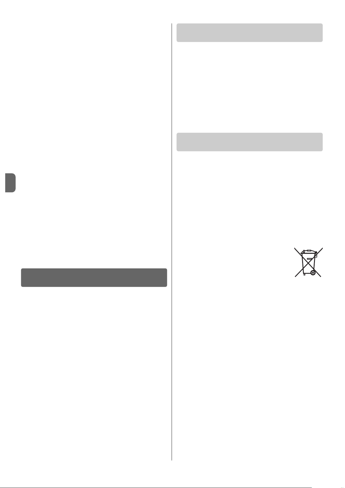
5 – Ogólne uwagi dotyczące obsługi systemu
Zwykle w przypadku, kiedy akumulator PSY24 nie jest odpowiednio doładowany, wyczerpuje swój zapas energii w ciągu kilku dni. Dlatego też po
zakończeniu montażu i podłączeniu systemu do automatyki, instalacja może
nie funkcjonować od razu (akumulator może być rozładowany w wyniku
zwykłego procesu samoczynnego rozładowania, które następuje z biegiem
czasu, również wówczas, kiedy był przechowywany w magazynie).
Akumulator PSY24 umożliwia automatyce wykonanie określonej ilości peł-
nych cykli (odwołaj się do ulotki zamieszczonej w opakowaniu). W związku z
tym, jeżeli nie jest stale doładowywany z pomocą panelu SYP lub sporadycznie z pomocą SYA1, może sygnalizować stan rozładowanego akumulatora
poprzez cykliczne miganie diody oraz sygnały dźwiękowe (sygnalizacja może
być tymczasowa lub stała).
W szczególności, kiedy jest zasilany przez panel SYP, doładowywanie może
ulegać wpływom zarówno warunków atmosferycznych, jak i intensywnego
używania automatyki, (kiedy przekraczana jest maksymalna ilość możliwych
pełnych cykli). Kiedy to nastąpi, PSY24 może sygnalizować stan rozładowa-
nego akumulatora.
Doładowanie akumulatora PSY24 może nastąpić na dwa sposoby:
A) -Ograniczenie używania automatyki w oczekiwaniu na większe nasło-
necznienie, umożliwiające doładowanie akumulatora w naturalny sposób, wykorzystując podłączenie go do panelu fotoelektrycznego SYP.
Aby przyspieszyć proces doładowywania odłącz akumulator PSY24 od
centrali sterującej automatyką i odczekaj kilka dni, aby panel fotoelektryczny SYP uzyskał wystarczającą ilość energii słonecznej, umożliwia-
jącą doładowanie akumulatora PSY24.
B) -Odłącz akumulator PSY24 od Centrali sterującej automatyką i od pane-
lu słonecznego SYP, (jeżeli występuje). Następnie wykonaj szybkie doładowanie akumulatora PSY24 w pomieszczeniu zabezpieczonym z
zastosowaniem zasilacza sieciowego SYA1.
Kiedy akumulator PSY24 jest doładowywany (z panelu fotoelektrycznego
SYP lub z zasilacza SYA1), czerwona dioda wysyła 2 krótkie błyski co 5
sekund. Sprawdź, czy ta sygnalizacja występuje również po zamontowaniu,
podczas, kiedy panel jest oświetlany przez słońce.
Sygnalizacja rozładowanego akumulatora kończy się, kiedy system osiąga
dostateczną autonomię elektryczną, umożliwiającą funkcjonowanie automatyki.
Jeżeli automatyka nie jest używana przez długi okres czasu, zaleca się odłączyć od akumulatora złączki automatyki oraz panel fotoelektryczny i prze-
chowywać akumulator w miejscu suchym i chłodnym.
CO ROBIĆ GDY...
(pomoc w rozwiązywaniu problemów)
UTYLIZACJA
KONSERWACJA OKRESOWA
• Centrala sterująca automatyką nie włącza się a akumulator PSY24 nie
wydaje żadnego sygnału.
Ta ka s yt u ac j a m oże być spowodowana błędnym podłączeniem lub źle wło-
żonymi żyłami elektrycznymi; jej przyczyną może być też całkowicie rozłado-
wany akumulator PSY24, który w związku z tym nie jest w stanie sygnalizować stanu rozładowanego akumulatora. W tym przypadku należy wykonać
szybkie ładowanie, wykorzystując w tym celu zasilacz SYA1 lub odczekać,
aż prawidłowo podłączony panel fotoelektryczny SYP rozpocznie ładowanie
akumulatora PSY24.
• Akumulator PSY24 rozładowuje się zbyt szybko.
Ta ka sy t ua c ja mo że być spowodowana zbytnim zużyciem akumulatora, który powinien zostać wymieniony. Przyczyną może też być zbyt intensywne
użytkowanie automatyki, przekraczające ograniczenia eksploatacyjne opisane w niniejszej instrukcji w Rozdziale 3.
• Akumulator PSY24 nie ładuje się.
Ta ka sy t ua c ja mo że być spowodowana nieprawidłowym funkcjonowaniem
panelu fotoelektrycznego SYP, w wyniku błędnego montażu lub nieprawidłowego podłączenia przewodów lub też przez nieprawidłowe funkcjonowanie
akumulatora PSY24.
Zwykle urządzenia będące częścią systemu nie wymagają szczególnej kon-
serwacji; tym niemniej przeprowadzanie regularnej kontroli umożliwia utrzymanie wydajności instalacji.
W związku z tym, aby prawidłowo wykonać konserwację, należy sprawdzać
co 6 miesięcy czy panel fotoelektryczny SYP nie jest zabrudzony (liśćmi, piaskiem, kurzem, itd.): co mogłoby wpłynąć na zmniejszenie jego wydajności.
Ponadto należy sprawdzać czy nie nadszedł czas wymiany akumulatora
PSY24, który w wyniku starzenia się będzie z czasem zmniejszał swoją
wydajność.
UWAGA – Ewentualna wymiana akumulatora PSY24 może zostać
przeprowadzona wyłącznie przez doświadczony i wykwalifikowany
personel.
Utylizacja urządzeń systemu
Te u r ządzenia są integralną częścią automatyki i w związku z tym muszą
być utylizowane razem z nią.
Zarówno operacje montażu jak również i demontażu po zakończeniu eksploatacji tych urządzeń, powinny być wykonywane przez personel wykwalifikowany.
Niniejsze urządzenia składają się z różnych rodzajów materiałów: niektóre z
nich mogą być ponownie używane, inne nadają się do wyrzucenia. Należy
zgromadzić niezbędne informacje dotyczące placówek zajmujących się
recyrkulacją lub utylizacją materiałów, zgodnie z przepisami obowiązującymi
dla danej kategorii urządzeń na Waszym terytorium.
Uwaga! - niektóre części urządzeń mogą zawierać substancje zanieczysz-
czające lub niebezpieczne, które, jeżeli zostaną porzucone bez nadzoru,
mogą wywierać szkodliwy wpływ na środowisko i zdrowie ludzkie.
Jak wskazuje symbol zamieszczony obok, zabrania się
wyrzucania tych urządzeń razem z odpadami domowymi.
Należy więc przeprowadzić “selektywną zbiórkę odpadów”,
zgodnie z metodami przewidzianymi przez przepisy obowiązujące na Waszym terytorium lub oddać urządzenia do
sprzedawcy podczas dokonywania zakupu nowych ekwiwalentnych urządzeń.
Uwaga! – lokalne przepisy obowiązujące mogą przewidywać wysokie kary
za nielegalną utylizację tych urządzeń.
Utylizacja akumulatora PSY24
Uwaga! – Akumulator zawiera substancje zanieczyszczające, nie należy go
więc wyrzucać razem z odpadami domowymi. Należy poddać go utylizacji
lub recyrkulacji stosując metody przewidziane przez przepisy obowiązujące
na Waszym terytorium.
4 – Polski
PL

NEDERLANDS
ALGEMENE AANBEVELINGEN EN VOORZORGS-
MAATREGELEN VOOR DE VEILIGHEID
Het ontwerp, de fabricage van de inrichtingen waaruit Solemyo-systeem bestaat en de informatie uit deze handleiding zijn volledig in overeenstemming met de geldende veiligheidsvoorschriften. Desondanks
kan een onjuiste installatie ernstig letsel toebrengen aan de personen
die het werk verrichten en aan de personen die de installatie zullen
gebruiken. Om deze reden is het belangrijk dat gedurende de installatie
alle aanwijzingen uit deze handleiding nauwgezet worden opgevolgd.
Als u twijfels van welke aard dan ook koestert, het product niet installeren en
u voor eventuele toelichtingen tot de Klantenservice van Nice wenden.
WERK IN VEILIGE CONDITIES!
Let op – Voor de veiligheid van de betrokken personen is het be langrijk deze aanwijzingen op te volgen.
Let op – Belangrijke aanwijzingen voor de veiligheid: bewaar de ze aanwijzingen.
Neem de volgende aanbevelingen in acht:
–voer uitsluitend de in deze handleiding voorziene elektrische aanslui-
tingen uit: een onjuiste totstandbrenging van de aansluitingen kan
ernstige schade aan het systeem veroorzaken.
–Als de voedingskabel die in de verpakking zit buitenshuis gebruikt zal
worden, is het verplicht deze over de volle lengte
te beschermen met
een specifieke beschermbuis voor elektriciteitskabels.
–kom niet met metalen voorwerpen aan de metalen delen van de aan-
sluitingen die zich op de kast van de accumulator bevinden.
Gezien de gevaarlijke situaties die zich gedurende de installatie en het
gebruik van het systeem kunnen voordoen, is het noodzakelijk de in richtingen die in de verpakking zitten te installeren met inachtneming
van de volgende aanbevelingen:
–voer geen andere wijzigingen uit op delen van de inrichtingen dan welke
voorzien zijn in deze handleiding. Niet-toegestane handelingen zullen
slechts storingen in de werking veroorzaken. De fabrikant aanvaardt geen
aansprakelijkheid voor schade die het gevolg is van op willekeurige wijze
gewijzigde inrichtingen.
–plaats de inrichtingen niet in de buurt van warmtebronnen en stel ze niet
bloot aan open vuur. Een dergelijke handelswijze kan de inrichtingen
beschadigingen, storingen, brand en gevaarlijke situaties veroorzaken.
–vermijd onderdompeling van de inrichtingen in water of andere vloeibare
substanties. Zorg ervoor dat er gedurende de installatie geen vloeistoffen
in het binnenste van de inrichtingen kunnen dringen.
–het verpakkingsmateriaal van de inrichtingen moet in overeenstemming
met de plaatselijk van kracht zijnde voorschriften als afval worden verwerkt.
Let op! –Bewaar deze handleiding zorgvuldig, deze zal u tot hulp zijn bij
eventuele toekomstige onderhoudswerkzaamheden of de vernietiging van
de afgedankte inrichtingen.
1 – Beschrijving en gebruiksbestemming
SOLEMYO is een autonoom voedingssysteem voor Nice-automatiseringen
voor poorten en garagedeuren (de lijst van de automatiseringen die voor dit
type voeding geschikt zijn, staat op het informatieblad in de verpakking en
kan ook geraadpleegd worden op de site www.niceforyou.com).
Ieder ander gebruik wordt als oneigenlijk beschouwd! De fabrikant is
niet aansprakelijk voor schade veroorzaakt door oneigenlijk gebruik
van de verschillende onderdelen van het systeem, anders dan het
gebruik dat in deze handleiding beoogd wordt.
Het Solemyo-systeem is bijzonder geschikt voor het van stroom voorzien
van automatiseringen die zich ver van het elektriciteitsnet bevinden.
Het systeem bestaat uit 3 basisinrichtingen, die onderling gecombineerd
kunnen worden om verschillende configuraties te verkrijgen, en is in staat om
zonne-energie of energie van het elektriciteitsnet op te slaan, om deze te
gebruiken wanneer de automatisering, waarop het systeem geïnstalleerd is,
dit vereist.
De verschillende inrichtingen van het systeem zijn verkrijgbaar in de volgende
verpakkingen:
- PSY24: dit is het hart van het systeem. De inrichting kan de door SYP ge -
durende de zonuren geproduceerde energie opslaan en deze op elk mo ment
van de dag ter beschikking stellen, ook op dagen dat het slecht weer is.
Dezelfde inrichting kan ook elektrische energie van het elektriciteitsnet op slaan, via SYA1. De verpakking bevat de accumulator PSY24, de kabels, de
connectors voor de aansluitingen op de automatisering, de be ves tigin g sonderdelen en deze handleiding;
- SYP: dit is een inrichting die in staat is het zonlicht rechtstreeks om te zet-
ten in elektrische energie. De verpakking bevat een zonnepaneel SYP voor
het opladen van PSY24 en de bevestigingsonderdelen;
- SYKCE: dit is een complete set voor autonome voeding via zonne-energie.
De verpakking bevat de inrichtingen PSY24, SYP, de kabels, de connectors
voor de aansluitingen op de automatisering, de bevestigingsonderdelen en
deze handleiding;
- SYA1: dit is een inrichting die dient voor het periodiek of in noodgevallen
opladen van PSY24; dit gebeurt via het normale elektriciteitsnet, en in een
overdekte omgeving. De verpakking bevat een batterijoplader SYA1.
2 – Controles voorafgaand aan de installatie
Om vast te stellen of het systeem geschikt is voor de eigenschappen van de
automatisering die het van stroom moet voorzien, dient u de controles uit te
voeren die in dit hoofdstuk worden beschreven en de conformiteit van de
resultaten ervan ook op basis van de technische gegevens uit het hoofdstuk
“Technische kenmerken”.
Bepaal welk punt in de nabijheid van de automatisering die van stroom moet
worden voorzien het meest geschikt is voor installatie van het zonnepaneel
en welk punt daarentegen het meest geschikt is voor de installatie van de
accumulator en houd hierbij rekening met de volgende, bindende factoren:
a) de gebruikslimieten die in dit hoofdstuk zijn beschreven;
b)de maximumlengte van de voedingskabel (3 m) en van de kabel van het
zonnepaneel (3 m);
c)de beschikbare ruimte in de nabijheid van de automatisering die van
stroom moet worden voorzien.
Voer daarnaast de volgende controles uit:
d)controleer of de oppervlakken die gekozen zijn om de twee inrichtingen te
monteren uit stevig materiaal bestaan en een stabiele bevestiging kunnen
garanderen.
e)controleer of elk van de te installeren inrichtingen in een tegen stoten
beschermde positie wordt opgesteld.
f)controleer voor elke inrichting de volgende punten:
SYP zonnepaneel
– controleer of de plaats die is gekozen voor de installatie het hele jaar
rond 100% direct zonlicht (volle zon) garandeert.
– controleer of het punt dat is gekozen voor de installatie van het paneel
ver uit de buurt is van begroeiing, muren of andere situaties die schaduwzones, ook gedeeltelijke
, kunnen creëren op het gevoelige oppervlak. Let
op! – dit oppervlak moet op ieder punt en op directe wijze door de
stralen van de zon worden verlicht; een gedeeltelijke schaduw, ook al
is die maar klein (bijvoorbeeld veroorzaakt door een blad of dergelijke), zal leiden tot een aanzienlijke verlaging van de energetische ca paciteit van het paneel.
– controleer of het mogelijk is het paneel in de correcte richting
en hoek
te plaatsen, zie de aanwijzingen in hoofdstuk 4.
KENNIS VAN HET SYSTEEM EN
VOORBEREIDING OP DE INSTALLATIE
Nederlands – 1
NL
Originele instructies

4 – Montage en aansluiting van de verschillende
componenten
STAP 1
–Optimale positie van het zonnepaneel SYP
In het algemeen moet het paneel zodanig geplaatst worden dat het constant
en op elk moment van de dag, het hele jaar door, door de zon verlicht wordt.
Dit bereikt u door een zorgvuldige plaatsing van het paneel zowel in horizontale als verticale richting; de juiste posities berekent u op basis van de plaats
van installatie van het paneel.
Na de controles uit hoofdstuk 2 te hebben uitgevoerd en de verschillende
installatiemogelijkheden van het paneel in aanmerking te hebben genomen,
zie afb. 6, verricht u de volgende handelingen:
INSTALLATIE VAN HET SYSTEEM
2 – Nederlands
NL
Basiscoëfficiënt (Cb) voor
het bereken van het maximumaantal
mogelijke manoeuvreercycli per dag
Maanden van het jaar
GRAFIEK A - Voor landen op 45° TEN NOORDEN van de evenaar
Basiscoëfficiënt (Cb) voor
het bereken van het maximumaantal
mogelijke manoeuvreercycli per dag
Maanden van het jaar
GRAFIEK B - Voor landen op 45° TEN ZUIDEN van de evenaar
Basiscoëfficiënt (Cb) voor
het bereken van het maximumaantal
mogelijke manoeuvreercycli per dag
Maanden van het jaar
GRAFIEK C - Voor landen op de evenaar
PSY24 accumulator
Om een optimaal rendement en lange levensduur van de accumulator te
verkrijgen, verdient het de voorkeur deze op te stellen op een punt – in
de nabijheid van de automatisering die van stroom moet worden voorzien – dat bescherming biedt tegen hoge zomerse en lage winterse temperaturen.
Het rendement van de lading van de accumulator hangt namelijk af van
de temperatuur van de omgeving waar de accumulator is geïnstalleerd:
een optimaal rendement wordt verkregen bij gemiddelde temperaturen
, bij
lage temperaturen daarentegen loopt het rendement aanzienlijk terug.
Een lange levensduur van de accumulator wordt daarentegen vooral
beïnvloed door hoge zomerse temperaturen, die de veroudering van de
onderdelen versnellen. De gemiddelde levensduur van de batterijen
bedraagt normaal gesproken circa 4-5 jaar; dit is ook afhankelijk van hoe
intensief de automatisering gebruikt wordt.
SYA1 batterijoplader
Zie het betreffende hoofdstuk in de instructiehandleiding van de inrichting.
3 – Gebruikslimieten van het systeem
HEEL BELANGRIJK
-Wanneer de automatisering van stroom wordt voorzien door het “So lemyo”-systeem, mag hij niet tegelijkertijd ook op het elektriciteits-
net zijn aangesloten en hierdoor gevoed worden.
-De inrichtingen SYP en SYA1, die energie aan de inrichting PSY24
leveren, moeten als alternatieven gebruikt worden, en niet tegelijkertijd.
• voor voeding via zonne-energie (met SYP)
De grafieken A, B en C geven de beschikbare zonne-energie aan, op basis
van de breedtegraad van de plaats van gebruik, op elk moment van het jaar,
met uitsluitend via de inrichtingen PSY24 en SYP van stroom voorziene automatisering. De curve van iedere grafiek wordt gegenereerd op grond van de
hoeveelheid licht per dag op een bepaalde breedtegraad, door het jaar heen.
Om het maximumaantal mogelijk cycli per dag te verkrijgen, dient u als volgt
te werk te gaan.
01. Zoek in de grafiek A, B of C (afhankelijk van de breedtegraad waarop
de installatie zich bevindt) de periode van het jaar die u interesseert;
zoek vervolgens op de verticale as de waarde “Cb” die met deze
periode overeenstemt, door het in de grafiek weergegeven voorbeeld
te volgen.
02. Gebruik deze waarde “Cb” tot slot om de berekeningen uit te voeren
die op het bijgevoegde blad staan.
Let op – Als het zonnepaneel gedurende de dag voor een deel van de tijd in
de schaduw blijft (met name tussen 10.00 uur en 14.00 uur), neemt het
maximumaantal mogelijke manoeuvreercycli af in functie van het aantal uren
dat er geen blootstelling aan de zon was.
Let op – Om het maximumaantal mogelijke cycli per dag te verhogen, is het
van fundamenteel belang het stroomverbruik van de automatisering te verlagen. Om deze reden is het belangrijk om op de besturingseenheden van de
automatiseringen de functie “Stand-by” in te programmeren en op het meest
doeltreffende niveau in te stellen (zie de handleiding van de automatisering).
• voor voeding via het vaste elektriciteitsnet (met SYA1)
Het opladen van de accumulator PSY24 via het vaste elektriciteitsnet dient te
gebeuren in een overdekte omgeving; koppel PSY24 eerst los van het zonnepaneel SYP en van de automatisering.
Afb. A

tor gedrukt, aan de onderkant ten opzichte van de klemmen en op de
tegenoverliggende zijde.
03. Na de twee draden te hebben vastgezet, dient u de connector in zijn
bescherming (afb. 10) te plaatsen.
Belangrijk – De correcte positie van de connector is met het symbool van de aardverbinding naar beneden toe (zie afb. 10);
04. Tre k v er vo lg en s de k ab el na ar d e bu it en ka nt va n de aa ns lu it in g toe en
installeer de afdichting en de ring (afb. 11-a-b). Schroef tot slot de
kabeldoorvoer (afb. 11-c) vast met behulp van een sleutel, zodat er een
compleet hermetische sluiting wordt verkregen.
05. Na de aansluiting gemonteerd te hebben, plaatst u de bijgeleverde
afdichting op het aansluitvlak van de aansluiting (afb. 12).
STAP 6 –Montage van de “pipet” aansluiting op de voedingskabel
Als de kabel te lang is, kunt u hem inkorten, waarbij u de draden zoveel
afstript dat de lengte ervan gelijk
is aan de lengte die is aangegeven op de
afb. A (let op! – afwijkende lengtes leveren problemen op bij de latere mon-
tage van de aansluiting).
Ga daarna als volgt te werk om de ZWARTE
“pipet” aansluiting op het uit-
einde van de voedingskabel te monteren:
01. Schuif de verschillende elementen van de aansluiting op de kabel, in de
volgorde die is aangegeven op afb. 7;
LET OP! – De elektrische geleidingsbrug op de connector (afb. 8) mag
niet gewijzigd worden.
02. Bevestig met behulp van een rechte schroevendraaier de blauwe
draad op klem nr. 1 en de bruine draad op de klem van de aardver-
binding (4) (afb. 9) op de connector:
Opmerking – De referentienummers en –symbolen zijn op de connector gedrukt, aan de onderkant ten opzichte van de klemmen en op de
tegenoverliggende zijde.
03. Na de twee draden te hebben vastgezet, dient u de connector in zijn
bescherming (afb. 10) te plaatsen.
Belangrijk – De correcte positie van de connector is met het symbool van de aardverbinding naar beneden toe (zie afb. 10);
04. Tre k v er vo lg en s de k ab el na ar d e bu it en ka nt va n de aa ns lu it in g toe en
installeer de afdichting en de ring (afb. 11-a-b). Schroef tot slot de
kabeldoorvoer (afb. 11-c) vast met behulp van een sleutel, zodat er een
compleet hermetische sluiting wordt verkregen.
05. Na de aansluiting gemonteerd te hebben, plaatst u de bijgeleverde
afdichting op het aansluitvlak van de aansluiting (afb. 12).
STAP 7 –Aansluiting van het zonnepaneel SYP op de accumulator
PSY24
Om het paneel aan te sluiten op de accumulator gaat u als volgt te werk:
01. Sluit de GRIJZE
“pipet” aansluiting aan op de “IN” aansluiting op de
accumulator (afb. 14);
02. Zet de aansluiting vast met de bijgeleverde veiligheidsschroef, zie afb.
15. Opmerking – Als u voorziet dat de aansluiting vaak van de accu-
mulator zal worden losgemaakt, gebruikt u de schroef van afb. 16-a. In
het andere geval gebruikt u de schroef van afb. 16-b.
STAP 8 – Aansluiting van de accumulator PSY24 op de
automatisering
LET OP! – Om veiligheidsredenen mogen de handelingen die worden beschreven in deze Stap 8 uitsluitend door een ge kwa li ficeerd en vakbekwame technicus worden verricht.
Om de accumulator aan te sluiten op de automatisering gaat u als volgt te
werk:
01. Open de besturingseenheid van de automatisering en steek de connector van de voedingskabel in de aansluiting die bestemd is voor de
bufferbatterij, op de eenheid. Om deze aansluiting te vinden, raadpleegt
u de instructiehandleiding van de automatisering die van stroom voorzien moet worden.
02. Sluit de ZWARTE
“pipet” aansluiting aan op de “OUT” aansluiting op
de accumulator (afb. 17);
03. Zet de aansluiting vast met de bijgeleverde veiligheidsschroef, zie afb.
18. Opmerking – Als u voorziet dat de aansluiting vaak van de accu-
mulator zal worden losgemaakt, gebruikt u de schroef van afb. 16-a. In
het andere geval gebruikt u de schroef van afb. 16-b.
Nederlands – 3
NL
• Bepaal de juiste richting van het paneel op het horizontale vlak door
als volgt te werk te gaan:
a) Bepaal op de plaats van installatie met behulp van een kompas of een
landkaart waar het NOORDEN en het ZUIDEN liggen.
b) Richt het paneel vervolgens naar het NOORDEN of het ZUIDEN, op basis
van de volgende overwegingen:
– als de plaats van installatie zich in een land ten noorden van de eve-
naar (Verenigde Staten; Europa; Rusland etc.) bevindt, moet het paneel
exact in ZUIDELIJKE richting worden gedraaid;
– als de plaats van installatie zich in een land ten zuiden van de evenaar (Latijns Amerika; Australië; Indonesië etc.) bevindt, moet het paneel
exact in NOORDELIJKE richting
worden gedraaid.
Zie voor meer duidelijkheid afb. 4.
• Bepaal de juiste richting van het paneel op het verticale vlak
door als
volgt te werk te gaan:
Er rekening mee houdend dat het maximale rendement van het paneel bij
voorkeur verkregen moet worden in de winterperiode, wanneer er minder
zonuren per dag zijn dan in de zomer, dient het paneel in een zodanige hoek
te worden gericht dat het de zonnestralen loodrecht (frontaal) op het gevoelige oppervlak ontvangt.
Deze hoek correspondeert met de breedtegraad van de plaats
en kan op
een willekeurige landkaart worden afgelezen: zo is de breedtegraad van
Madrid bijvoorbeeld 40°; die van Venetië 45°; die van Londen circa 50° etc.
Zie voor meer duidelijkheid afb. 5.
STAP 2 –Bevestiging van het zonnepaneel SYP op het gekozen punt
Na de positie van het paneel exact te hebben bepaald, assembleert u alle
componenten van de draagbeugel aan de hand van de aanwijzingen van
afb. 3.
To t slot be ve stigt u de be ug e l va n h et pa ne e l op he t ge ko z en o p pe rv l ak ,
zoals te zien is op afb. 6.
STAP 3 –Bevestiging van de accumulator PSY24 op het
gekozen punt
Na de controles uit hoofdstuk 2 te hebben uitgevoerd en de plaats van installatie van de accumulator exact te hebben bepaald, de accumulator op het
gekozen oppervlak bevestigen, zoals te zien is op afb. 13. Opmerking –
Gebruik voor de bevestiging de 2 schroeven aan de onderkant alleen als u
de accumulator vast wilt verankeren (niet verplaatsbaar).
STAP 4 – Doorvoer van de kabels
Na het paneel en de accumulator te hebben bevestigd, voert u de kabel van
het paneel door de buis of het beschermkanaal tot aan de accu mulator.
Raadpleeg de instructiehandleiding van de automatisering die van stroom
voorzien moet worden en verwijder het beschermdeksel van de besturingseenheid. Voer vervolgens het uiteinde van de voedingskabel met gestripte
draden door de automatisering (waar de andere kabels lopen) en laat hem uit
de automatisering komen via de hiervoor bestemde kabeldoorvoer. Voer de
kabel tot slot door de eventuele beschermgoot tot aan de accumulator.
Let op! – Sluit de voedingskabel niet aan op de besturingseenheid; laat de
toegang tot de besturingseenheid open en laat de kabeldoorvoer los.
STAP 5 –Montage van de ”pipet” aansluiting op de kabel van het
zonnepaneel SYP
Als de kabel te lang is, kunt u hem inkorten, waarbij u de draden zoveel
afstript dat de lengte ervan gelijk is aan de lengte die is aangegeven op de
afb. A (let op! – afwijkende lengtes leveren problemen op bij de latere mon-
tage van de aansluiting).
Ga daarna als volgt te werk om de GRIJZE “pipet” aansluiting op het uitein-
de van de kabel van het paneel te monteren:
01. Schuif de verschillende elementen van de aansluiting op de kabel, in de
volgorde die is aangegeven op afb. 7;
LET OP! – De elektrische geleidingsbrug op de connector (afb. 8) mag
niet gewijzigd worden.
02. Bevestig met behulp van een rechte schroevendraaier de blauwe
draad op klem nr. 1 en de bruine draad op de klem van de aardverbinding (4) (afb. 9) op de connector:
Opmerking – De referentienummers en –symbolen zijn op de connec-
BELANGRIJK! – Als de voedingskabel die in de verpakking
zit buitenshuis gebruikt zal worden, is het verplicht deze
over de volle lengte
te beschermen met een specifieke
beschermbuis voor elektriciteitskabels.
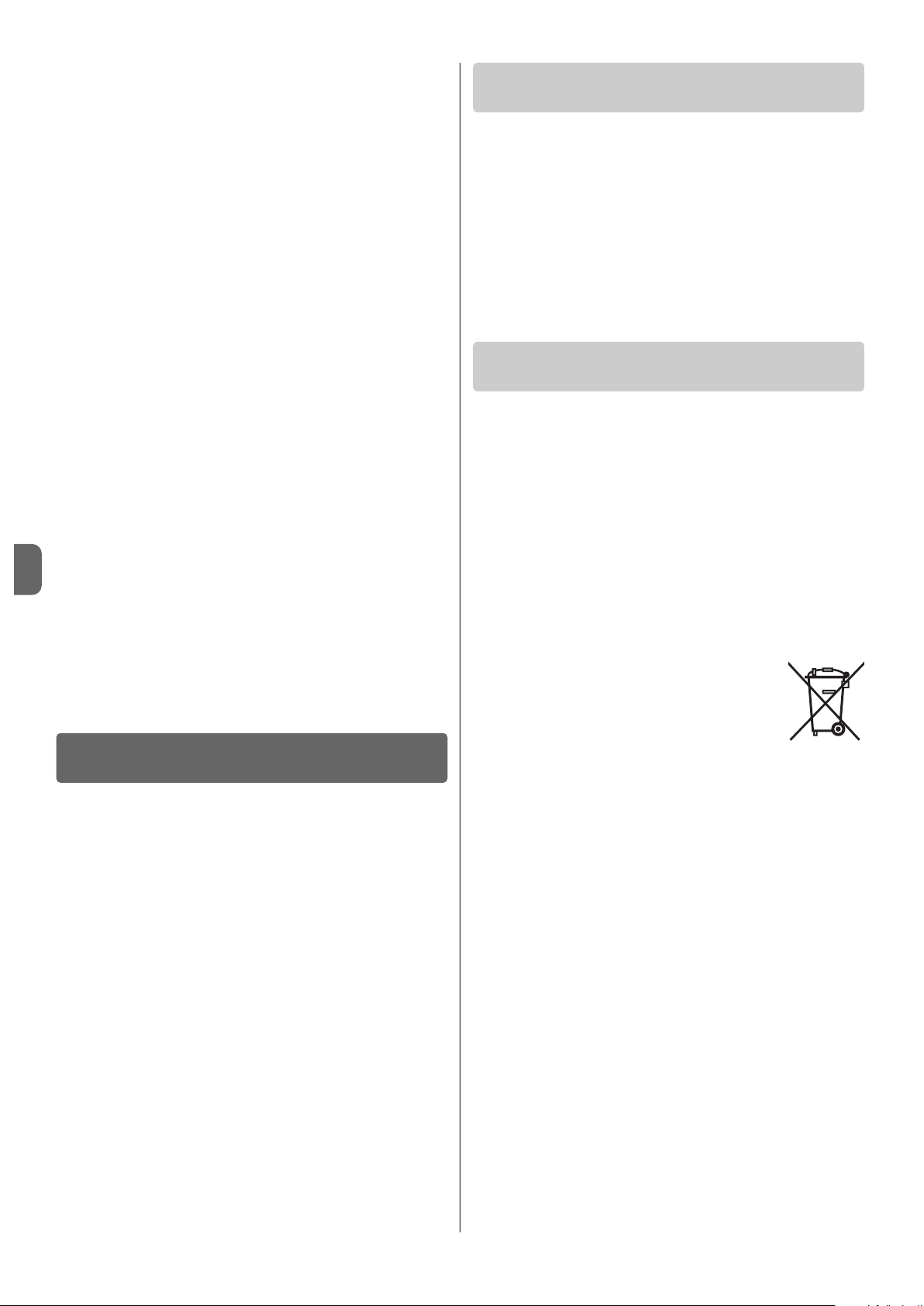
• De besturingseenheid van de automatisering niet inschakelt en de
accumulator PSY24 geen enkele signalering geeft.
Dit kan afhangen van niet-correcte aansluitingen of van niet perfect ingestoken elektriciteitsdraden; het is ook mogelijk dat de accumulator PSY24 helemaal leeg is en niet voldoende energie heeft om de status lege batterij te sig-
naleren.
In dit geval is het nodig een snelle oplaadcyclus uit te voeren met behulp van
de batterijoplader SYA1, of te wachten tot het zonnepaneel SYP, correct
aangesloten, de accumulator PSY24 begint op te laden.
• De accumulator PSY24 de neiging heeft te snel te ontladen.
Dit kan afhangen van overmatige veroudering van de accumulator, die in dit
geval het beste vervangen kan worden; daarnaast kan dit probleem veroorzaakt worden door een te intensief gebruik van de automatisering, waarbij de
in Hoofdstuk 3 van deze handleiding aangegeven voorziene gebruikslimieten
worden overschreden.
• De accumulator PSY24 niet meer oplaadt.
Dit kan afhangen van een storing van het zonnepaneel SYP, als gevolg van
een onjuiste installatie ervan, van een verkeerde aansluiting van de kabels of
van een storing van de accumulator PSY24.
Over het algemeen behoeven de inrichtingen van het systeem geen speciaal
onderhoud; door de installatie in de loop van de tijd regelmatig te controleren, kunt u deze echter altijd in goede staat van werking houden.
Voor een juist onderhoud dient u eens in de 6 maanden te controleren of er
zich geen vuil op het zonnepaneel heeft opgehoopt (bijvoorbeeld bladeren,
zand etc.): het rendement van een vuil paneel kan namelijk verminderen.
Daarnaast is het noodzakelijk te controleren of de accumulator vervangen
moet worden. Door veroudering kan de autonomie van de accumulator in de
loop der tijd namelijk afnemen.
LET OP – De eventuele vervanging van de accumulator PSY24 mag uitsluitend worden uitgevoerd door gekwalificeerd en ervaren personeel.
5 – Algemene opmerkingen over het gebruik van het
systeem
Over het algemeen zal de energiereserve van de accumulator PSY24, wanneer deze niet goed wordt opgeladen, binnen enkele dagen opraken. Om
deze reden is het mogelijk dat het systeem, nadat men dit na afloop van de
installatie op de automatisering heeft aangesloten, niet meteen operatief is
(de accumulator kan leeg zijn als gevolg van het normale ontladingsproces
dat met de tijd plaatsvindt, ook wanneer het product zich in het magazijn
bevindt).
De accumulator PSY24 laat een bepaald aantal manoeuvreercycli van de
automatisering toe (zie het informatieblad in de verpakking). Als de accumulator daarom niet constant wordt bijgeladen met SYP of af en toe met
SYA1, kan de status lege batterij gesignaleerd worden aan de hand van
knipperreeksen van de led’s en pieptonen (de signalering kan tijdelijk of
permanent zijn).
Bij het opladen met SYP kan het oplaadproces zowel beïnvloed worden door
de weersomstandigheden als door een intensief gebruik van de automatisering (overschrijding van het maximumaantal mogelijke manoeuvreercycli).
Wanneer dit gebeurt, kan de PSY24 de status lege batterij signaleren.
De PSY24 kan op één van de volgende manieren worden bijgeladen:
A) - Beperk het gebruik van de automatisering in afwachting van een verbe-
tering van de zoncondities, zodat de accumulator zich op natuurlijke
wijze kan bijladen via de aansluiting op het zonnepaneel SYP.
Om het oplaadproces te versnellen, koppelt u de PSY24 los van de
besturingseenheid van de automatisering en wacht u een paar dagen
totdat het zonnepaneel SYP voldoende zonne-energie heeft ontvangen
om de accumulator PSY24 weer op te laden.
B) -Koppel de accumulator PSY24 los van de besturingseenheid en het
zonnepaneel SYP (indien aanwezig). Laad de PSY24 in een overdekte
omgeving op via het elektriciteitsnet, met de batterijoplader SYA1.
Wanneer de accumulator PSY24 aan het opladen is (via zonnepaneel SYP of
batterijoplader SYA1), zal de rode led iedere 5 seconden 2 maal kort knipperen. Controleer of deze signalering ook na de installatie, wanneer het paneel
verlicht wordt door de zon, aanwezig is.
De signalering voor lege batterij stopt wanneer het systeem een elektrische
autonomie bereikt die volstaat om de automatisering te kunnen laten functioneren.
Als de automatisering voor lange tijd niet gebruikt zal worden, wordt aanbevelen de connectors van de automatisering en van het zonnepaneel los te
maken van de accumulator en de accumulator op een koele en droge plaats
te bewaren.
Afdanken van de inrichtingen van het systeem
Deze inrichtingen maken integraal deel uit van de automatisering en
moeten daarom samen met de automatisering worden afgedankt.
De ontmantelingwerkzaamheden aan het eind van de levensduur van deze
inrichtingen moeten, net als de installatiewerkzaamheden, worden uitgevoerd door gekwalificeerd personeel.
Deze inrichtingen bestaat uit verschillende soorten materiaal: sommigen hiervan kunnen gerecycled worden, anderen moeten als afval worden verwerkt.
Win informatie in over de recycling- of afvalverwerkingsystemen die voor
deze categorie van inrichtingen zijn voorzien door de in uw land geldende
voorschriften.
Let op! – sommige delen van de inrichtingen kunnen vervuilende of gevaarlijke substanties bevatten die, indien ze in het milieu terechtkomen, schadelijke effecten kunnen hebben op de omgeving of op de gezondheid van personen.
Zoals aangegeven door het symbool hiernaast, is het verboden deze inrichtingen met het gewone huisvuil weg te
gooien. Volg een “gescheiden af valverwerking” volgens de
methodes die voorzien zijn door de in uw land geldende
voorschriften, of lever de inrichtingen weer in bij de verkoper op het moment dat u nieuwe gelijksoortige inrichtingen
aanschaft.
Let op! – De plaatselijk geldende voorschriften kunnen zware sancties voorzien in het geval u de voorschriften voor afvalverwerking van deze inrichtingen niet opvolgt.
Afdanken van de accumulator PSY24
Let op! – De accumulator bevat vervuilende substanties en mag na verwijdering dan ook niet met het gewone huisvuil worden weggegooid. De accumulator dient als afval te worden verwerkt of gerecycled volgens de me thoden
die voorzien zijn door de voorschriften die van kracht zijn in uw land.
WAT TE DOEN ALS...
(handleiding voor het oplossen van problemen)
PERIODIEK ONDERHOUD
AFDANKEN
4 – Nederlands
NL

I
EN - Technical documentatio n
Images
IT - Documentazione Tecnica
Immagini
FR - Documentation Technique
Images
ES - Documentación Técnica
Imágenes
DE - echnische Dokumentation
Bilder
PL - Dokumentacja Techniczna
Zdjęcia
NL - Technische documenta tie
Afbeeldingen
NL PL
DE
ES
FR
IT
EN

WARNINGS: • All technical specifications stated herein refer to an ambient temperature of 20°C (± 5°C) • Nice S.p.a. reserves the right to apply modifications to the
product at any time as deemed necessary, while maintaining the same functionalities and intended use • SYKCE guarantees the minimum number of manoeuvres per
day, exclusively with the photovoltaic panel positioned correctly and in the conditions as specified in Chapter 3.
PSY24 BATTERY
DESCRIPTION DATA
Rated voltage: 24 V
Maximum current: 10 W
Rated battery capacity: 20 Ah
Protection rating: IP 44
Operation temperature: - 20° C ÷ + 50 °C (0 °C, - +40 °C when charging using the back-up power supply unit connected to the mains)
Complete recharging time: approx. 15 hours (when charging using the back-up power supply unit connected to the mains)
Dimensions: 258 mm x 235 mm x 180 mm
Weight: 14 kg
Note – The batteries in the PSY24 unit are VRLA (Valve Regulated Lead Acid Batteries). They comply with the specific provision A67 of the IATA/ICAAO
regulation governing hazardous goods. PSY24 is therefore not considered hazardous goods and may be transported without any risk by air, sea and on
road.
SYP PHOTOVOLTAIC PANEL
DESCRIPTION DATA
Rated voltage: 24 V
Peak power: 15 Wp
Operation temperature: -40 °C ÷ +85 °C
Dimensions: 390 mm x 415 mm x 28 mm
Weight: 1,9 kg
Warning – The glass of the photovoltaic panel has been tested to resist to hailstones and medium entity impact. In the event of particularly consistent hail
or impact, the glass may be damaged; in this case contact the Nice Technical Assistance service.
TECHNICAL SPECIFICATIONS
II
EN
EC declaration of conformity
Declaration in accordance with the Directives: 2006/95/EC (LVD) and 2004/108/EC (EMC)
Note: The contents of this declaration correspond to declarations in the official document deposited at the registered offices of Nice S.p.a. and in particular to the last revision available before printing this manual. The text herein has been re-edited for editorial purposes. A copy of the original declaration
can be requested from Nice S.p.a. (TV) I.
Declaration number: 285/PSY(...)
Revision: 1
Language: EN
Manufacturer’s name: NICE S.p.A.
Address: Via Pezza Alta N°13, 31046 Rustignè di Oderzo (TV) Italy
Ty pe of pr o du c t: Nice solar kit
Model / Type: SYKCE kit comprises the SYP photovoltaic panel and the PSY24 battery
Accessories: SYA1
The undersigned, Luigi Paro, in the role of Managing Director, declares under his sole responsibility, that the product specified above conforms to the provisions of the following directives:
• Directive 2006/95/EC OF THE EUROPEAN PARLIAMENT AND COUNCIL of 12 December 2006 regarding the approximation of member state legislation related to electrical material destined for use within specific voltage limits, according to the following harmonised standards:
EN 60335-1:2002 + A1:2004 + A11:2004 + A12:2006 + A2:2006 + A13:2008
• DIRECTIVE 2004/108/EC OF THE EUROPEAN PARLIAMENT AND COUNCIL of 15 December 2004 regarding the approximation of member state legislation related to electromagnetic compatibility, repealing directive 89/336/EEC, according to the following standards:
EN 61000-6-2:2005, EN 61000-6-3:2007
Oderzo, 17 March 2010
Ing. Luigi Paro
(Managing director)

Dichiarazione CE di conformità
Dichiarazione in accordo alle Direttive: 2006/95/CE (LVD) e 2004/108/CE (EMC)
Nota: Il contenuto di questa dichiarazione corrisponde a quanto dichiarato nel documento ufficiale depositato presso la sede di Nice S.p.a. e, in particolare, alla sua ultima revisione disponibile prima della stampa di questo manuale. Il testo qui presente è stato riadattato per motivi editoriali. Copia della
dichiarazione originale può essere richiesta a Nice S.p.a. (TV) I.
Numero dichiarazione: 285/PSY(...)
Revisione: 1
Lingua: IT
Nome produttore: NICE S.p.A.
Indirizzo: Via Pezza Alta N°13, 31046 Rustignè di Oderzo (TV) Italy
Tipo di prodotto: Kit solare Nice
Modello / Tipo: Kit SYKCE composto dal pannello fotovoltaico SYP e dall’accumulatore PSY24
Accessori: SYA1
Il sottoscritto Luigi Paro in qualità di Amministratore Delegato, dichiara sotto la propria responsabilità che il prodotto sopra indicato risulta conforme alle
disposizioni im poste dalle seguenti direttive:
• Direttiva 2006/95/CE DEL PARLAMENTO EUROPEO E DEL CONSIGLIO del 12 dicembre 2006 concernente il ravvicinamento delle legislazioni degli
Stati membri relative al materiale elettrico destinato ad essere adoperato entro taluni limiti di tensione, secondo le seguenti norme armonizzate:
EN 60335-1:2002 + A1:2004 + A11:2004 + A12:2006 + A2:2006 + A13:2008
• DIRETTIVA 2004/108/CE DEL PARLAMENTO EUROPEO E DEL CONSIGLIO del 15 dicembre 2004 concernente il ravvicinamento delle legislazioni
degli Stati membri relative alla compatibilità elettromagnetica e che abroga la direttiva 89/336/ CEE, secondo le seguenti norme armonizzate:
EN 61000-6-2:2005, EN 61000-6-3:2007
Oderzo, 17 marzo 2010
Ing. Luigi Paro
(Amministratore Delegato)
AVV ERTE NZE: • Tut te l e ca ra tt er is ti ch e te c ni ch e ri po rt at e, s on o ri fe ri te a d un a te mp er at ur a am bi en ta le d i 20 °C ( ± 5° C) • N ic e S. p. a. s i ri se r va il diritto di apportare modifi-
che al prodotto in qualsiasi momento lo riterrà necessario, mantenendone comunque la stessa funzionalità e destinazione d’uso • SYKCE garantisce il numero massimo
possibile di manovre al giorno, esclusivamente con il pannello fotovoltaico correttamente orientato e nelle condizioni indicate nel Capitolo 3.
PANNELLO FOTOVOLTAICO SYP
DESCRIZIONE DATI
Te ns i on e n o mi n al e : 24 V
Potenza di picco: 15 Wp
Te mp e ra t ur a d ’ im p ie g o: -40 °C ÷ +85 °C
Dimensioni: 390 mm x 415 mm x 28 mm
Peso: 1,9 kg
Avvertenza –Il vetro del pannello fotovoltaico è testato per resistere alla grandine e agli urti di media entità. In caso di grandine o urti particolarmente con-
sistenti, il vetro potrebbe danneggiarsi; in questi casi rivolgersi al Servizio Assistenza Tecnica Nice.
ACCUMULATORE PSY24
DESCRIZIONE DATI
Te ns i on e n o mi n al e : 24 V
Corrente massima: 10 A
Capacità nominale della batteria: 20 Ah
Grado di protezione: IP 44
Te mp e ra t ur a d ’ im p ie g o: -20 °C ÷ +50 °C (0 °C ÷ +40 °C quando è in carica con l’utilizzo dell’alimentatore da rete fissa)
Te mp o d i r i ca r ic a c o mp l et a : 15 ore circa (con l’utilizzo dell’alimentatore da rete fissa)
Dimensioni: 258 mm x 235 mm x 180 mm
Peso: 14 kg
Nota –Le batterie presenti nell’accumulatore PSY24 sono del tipo VRLA (Valve Regulated Lead Acid Batteries), cioè ermetiche e regolate da una valvola.
Sono conformi alla specifica disposizione A67 del Regolamento IATA/ICAAO per le merci pericolose. PSY24 non è quindi da considerarsi merce pericolosa; pertanto può essere trasportato senza alcun rischio via aerea, via mare e su strada.
CARATTERISTICHE TECNICHE
III
IT

ACCUMULATEUR PSY24
AVERTISSEMENT S : • Tou t es le s c a ra c té r is t iq u es t e ch n iq u es in d iq u ée s s e r éf è re nt à u ne t e mp é ra t ur e a mb i an t e d e 20 °C (± 5 °C ) • N i ce S. p .a . s e r és erve le droit d’ap-
porter des modifications au produit à tout moment si elle le jugera nécessaire, en garantissant dans tous les cas les mêmes fonctions et le même type d’utilisation prévu
• SYKCE garantit le nombre maximum possible de manoeuvres par jour, exclusivement avec le panneau photovoltaïque correctement orienté et dans les conditions indiquées dans le Chapitre 3.
PANNEAU SOLAIRE PHOTOVOLTAÏQUE SYP
DESCRIPTION DONNÉES
Te ns i on no m in a le : 24 V
Courant maximum : 10 W
Capacité nominale de la batterie : 20 Ah
Indice de protection : IP 44
Te mp é ra t ur e d ’ em p lo i : -20 °C ÷ +50 °C (0 °C ÷ +40 °C quand elle est en charge avec l’utilisation du bloc d’alimentation de secteur)
Te mp s d e r e ch a rg e c o mp l èt e : 15 heures environ (avec l’utilisation du bloc d’alimentation de secteur)
Dimensions : 258 mm x 235 mm x 180 mm
Poids : 14 kg
Note – Les batteries présentes dans l’accumulateur PSY24 sont du type VRLA (Valve Regulated Lead Acid Batteries), c’est-à-dire étanches et réglées par
une soupape. Elles sont conformes à la disposition A67 spécifique du Règlement IATA/ICAAO pour les marchandises dangereuses. PSY24 ne doit donc
pas être considéré comme une marchandise dangereuse ; Il peut donc être transporté sans aucun risque par voie aérienne, maritime et sur route.
DESCRIPTION DONNÉES
Te ns i on no m in a le : 24 V
Puissance de crête : 15 Wp
Te mp é ra t ur e d ’ ut i li s at i on : -40 °C ÷ +85 °C
Dimensions : 390 mm x 415 mm x 28 mm
Poids : 1,9 kg
Avertissement –Le verre du panneau photovoltaïque est testé pour résister à la grêle et à des impacts de moyenne entité. En cas de grêle ou d’impacts
particulièrement violents, le verre pourrait s’endommager ; dans ce cas s’adresser au SAV Nice.
CARACTÉRISTIQUES TECHNIQUES
IV
FR
Déclaration CE de conformité
Déclaration conformément aux Directives : 2006/95/CE (LVD) et 2004/108/CE (EMC)
Note :Le contenu de cette déclaration de conformité correspond à ce qui est déclaré dans le document officiel, déposé au siège de Nice S.p.a., et en
particulier à sa dernière révision disponible avant l’impression de ce guide. Ce texte a été réadapté pour des motifs éditoriaux. Une copie de la déclaration
originale peut être demandée à Nice S.p.a. (TV) I.
Numéro déclaration :285/PSY(...)
Révision :1
Langue :FR
Nom producteur :Nice S.p.a.
Adresse :Via Pezza Alta N°13, 31046 Rustignè di Oderzo (TV) Italie
Ty pe de pr o du i t : Kit solaire Nice
Modèle / Type : Kit SYKCE composé du panneau photovoltaïque SYP et de l’accumulateur PSY24
Accessoires : SYA1
Je soussigné Luigi Paro en qualité d’Administrateur Délégué, déclare sous mon entière responsabilité que le produit susmentionné est conforme aux dispositions imposées par les directives suivantes :
•DIRECTIVE 2006/95/CEE DU PARLEMENT EUROPÉEN ET DU CONSEIL du 12 décembre 2006 concernant le rapprochement des législations des
États membres relatives au matériel électrique destiné à être employé dans certaines limites de tension, selon les normes harmonisées suivantes :
EN 60335-1:2002 + A1:2004 + A11:2004 + A12:2006 + A2:2006 + A13:2008
•DIRECTIVE 2004/108/CE DU PARLEMENT EUROPÉEN ET DU CONSEIL du 15 décembre 2004 concernant le rapprochement des législations des
États membres relatives à la compatibilité électromagnétique et qui abroge la directive 89/336/ CEE, selon les normes harmonisées suivantes :
EN 61000-6-2:2005, EN 61000-6-3:2007
Oderzo, le 17 mars 2010
Ing. Luigi Paro
(Administrateur Délégué)

ACUMULADOR PSY24
DESCRIPCIÓN DATOS
Te ns i ón no m in a l 24 V
Potencia máxima: 10 W
Capacidad nominal de la batería: 20 Ah
Clase de protección: IP 44
Te mp e ra t ur a d e f u nc i on a mi e nt o : -20 °C ÷ +50 °C (0 °C ÷ +40 °C
cuando se está cargando con el alimentador de red fija
)
Tiempo de recarga completa: 15 horas aprox.
(utilizando el alimentador de red fija)
Dimensiones: 258 mm x 235 mm x 180 mm
Peso: 14 kg
Nota - Las baterías del PSY24 son del tipo VRLA (Valve Regulated Lead Acid Batteries), es decir herméticas y reguladas por una válvula. Responden a la
disposición específica A67 del Reglamento IATA/ICAAO para las mercancías peligrosas. El PSY24 no debe considerarse como mercancía peligrosa; por
lo que puede ser transportada sin riesgos por vía aérea, por vía marítima o por carretera.
PANEL FOTOVOLTAICO SYP
DESCRIPCIÓN DATOS
Te ns i ón no m in a l 24 V
Potencia pico: 15 Wp
Te mp e ra t ur a d e f u nc i on a mi e nt o : -40 °C ÷ +85 °C
Dimensiones: 390 mm x 415 mm x 28 mm
Peso: 1,9 kg
Advertencia – El vidrio del panel fotovoltaico ha sido fabricado para resistir el granizo y los golpes de intensidad mediana. En el caso de granizo o de gol-
pes muy fuertes, el vidrio podría romperse; en este caso, contacte con el Servicio de Asistencia Técnica Nice.
ADVERTENCIAS: • Tod a s l as ca r ac t er í st i ca s t é cn i ca s i n di c ad a s s e r ef i er en a u na te m pe r at u ra am b ie n te de 20 ° C ( ± 5 °C ) • Ni c e S .p . a. se re se r va el derecho de modifi-
car el producto en cualquier momento en que lo considere necesario, conservando las mismas funciones y el mismo uso previsto • SYKCE garantiza el número máximo
posible de maniobras por día, sólo con el panel fotovoltaico orientado correctamente y en las condiciones indicadas en el Capítulo 3.
CARACTERÍSTICAS TÉCNICAS
V
ES
Declaración de conformidad CE
Declaración de conformidad con las Directivas: 2006/95/CE (LVD) y 2004/108/CE (CEM)
Nota:el contenido de esta declaración corresponde a aquello declarado en el documento oficial depositado en la sede de Nice S.p.a., y en particular, a
su última revisión disponible antes de la impresión de este manual. El presente texto ha sido readaptado por motivos de impresión. La copia de la declaración original puede solicitarse a Nice S.p.a. (TV) I.
Número de declaración:285/PSY(...)
Revisión:1
Idioma:ES
Nombre del fabricante:Nice S.p.a.
Dirección:via Pezza Alta, 13 31046 Rustignè di Oderzo (TV) Italia
Tipo de producto: Kit solar Nice
Modelo / Tipo: Kit SYKCE compuesto de panel fotovoltaico SYP y del acumulador PSY24
Accesorios:SYA1
El suscrito, Luigi Paro, en su carácter de Administrador Delegado, declara bajo su responsabilidad que el producto antedicho cumple con las disposiciones establecidas por las siguientes directivas:
•Directiva 2006/95/CE DEL PARLAMENTO EUROPEO Y DEL CONSEJO del 12 de diciembre de 206 sobre de la aproximación de las legislaciones de
los Estados miembros relativas al material eléctrico destinado a ser utilizado dentro de determinados límites de tensión, según las siguientes normas
armonizadas: EN 60335-1:2002 + A1:2004 + A11:2004 + A12:2006 + A2:2006 + A13:2008
•DIRECTIVA 2004/108/CE DEL PARLAMENTO EUROPEO Y DEL CONSEJO del 15 de diciembre de 2004 sobre la aproximación de las legislaciones de
los Estados miembros relativas a la compatibilidad electromagnética y que abroga la Directiva 89/336/CEE, según las siguientes normas:
EN 61000-6-2:2005, EN 61000-6-3:2007
Oderzo, 17 de marzo 2010
Ing. Luigi Paro
(Administrador delegado

HINWEISE • Alle angegebenen technischen Merkmale beziehen sich auf eine Temperatur von 20°C (± 5°C). • Nice behält sich das Recht vor, jederzeit als nötig
betrachtete Änderungen am Produkt vorzunehmen, wobei die Funktionalitäten und der Einsatzzweck beibehalten werden.• SYKCE garantiert die mögliche Höchstzahl der Bewegungen pro Tag nur, wenn der Photovoltaikkollektor korrekt ausgerichtet ist und die Bedingungen laut Kapitel 3 einhält.
AKKUMULATOR PSY24
BESCHREIBUNG DATEN
Netzspannung: 24 V
Höchststrom: 10 W
Nennkapazität der Batterie: 20 Ah
Schutzart: IP 44
Betriebstemperatur: -20 °C ÷ +50 °C (0 °C ÷ +40 °C (0 °C ÷ +40 °C, wenn er mit dem Festnetzspeisegerät aufgeladen wird)
TVollständige Ladezeit: Zirka 15 Stunden (bei Anwendung des Festnetzspeisegeräts)
Abmessung: 258 mm x 235 mm x 180 mm
Gewicht: 14 kg
Hinweis – Die Batterien in dem Akkumulator PSY24 sind VRLA-Batterien (Valve Regulated Lead Acid), d.h. hermetisch und durch ein Ventil geregelt. Sie
entsprechen der Anweisung A67 der Regelung IATA/ICAAO für gefährliche Waren. PSY24 ist somit nicht als gefährliche Ware zu betrachte und kann ohne
Risiko per Flugzeug, Schiff oder auf Straßen transportiert werden.
KOLLEKTOREN FÜR PHOTOVOLTAIK SYP
BESCHREIBUNG DATEN
Netzspannung: 24 V
Spitzenleistung: 15 Wp
Betriebstemperatur: -40 °C ÷ +85 °C
Abmessung: 390 mm x 415 mm x 28 mm
Gewicht: 1,9 kg
Hinweis – Das Glas des Kollektors für Photovoltaik wurde auf die Festigkeit gegen Hagel- und mittelstarke Stöße getestet. Bei besonders starkem Hagel
oder Stößen könnte das Glas beschädigt werden, in diesem Fall wendet man sich an den Technischen Kundendienst Nice.
TECHNISCHE EIGENSCHAFTEN
VI
DE
CE-Konformitätserklärung
Erklärung in Übereinstimmung mit den folgenden Richtlinien: 2006/95/CE (LVD) e 2004/108/CE (EMC)
Anmerkung: Der Inhalt dieser Konformitätserklärung entspricht dem in den offiziellen Unterlagen angegebenen, die sich im Firmensitz der Nice S.p.a.
befinden, und insbesondere der vor dem Druck dieser Anleitung verfügbaren, letzten Revision. Der hier vorhandene Text wurde aus Verlagsgründen angepasst. Eine Kopie der ursprünglichen Erklärung jedes Produkts kann bei Nice S.p.a. angefordert werden. (TV) I.
Erklärungsnummer: 285/PSY(...)
Revision:1
Sprache: DE
Herstellername: NICE s.p.a.
Adresse: Via Pezza Alta N°13, 31046 Rustignè di Oderzo (TV) Italien
Produkttyp: Solar-Set Nice
Modell / Typ: Set (Bausatz) SYKCE, bestehend aus dem Photovoltaik-Kollektor SYP und dem Akkumulator PSY24
Zubehör: SYA1
Der Unterzeichnende Luigi Paro erklärt als Geschäftsführer unter seiner Haftung, dass das oben genannte Produkt den Vorschriften der folgenden Richtlinien entspricht:
•2006/95/EWG RICHTLINIE DES EUROPÄISCHEN PARLAMENTS UND DES RATS vom 12. Dezember 2006 bezüglich der Annäherung der Gesetze
der Mitgliedsstaaten hinsichtlich elektrischen Materials, das innerhalb bestimmter Spannungslimits verwendet wird und zwar gemäß den folgenden
übereinstimmenden Normen: EN 60335-1:2002 + A1:2004 + A11:2004 + A12:2006 + A2:2006 + A13:2008
•2004/108/EWG RICHTLINIE DES EUROPÄISCHEN PARLAMENTS UND RATS vom 15. Dezember 2004 bezüglich der Annäherung der Gesetzgebungen der Mitgliedsstaaten, was die elektromagnetische Verträglichkeit betrifft und die Richtlinie 89/336/EWG aufhebt und zwar gemäß den folgenden
übereinstimmenden Normen: EN 61000-6-2:2005, EN 61000-6-3:2007
Oderzo, den 17. März 2010
Ing. Luigi Paro
(Geschäftsführer)

AKUMULATOR PSY24
OPIS DANE
Napięcie znamionowe: 24 V
Prądmaksymalny:
10 W
Znamionowa pojemność akumulatora: 20 Ah
Stopień ochrony: IP 44
Te mp e ra t ur a p r ac y : -20 °C ÷ +50 °C (0 °C ÷ +40 °C w przypadku doładowywania z zastosowaniem zasilacza sieciowego)
Czas pełnego ładowania: 15 ore circa (z zastosowaniem zasilacza sieciowego)
Wymiary: 258 mm x 235 mm x 180 mm
Masa: 14 kg
Uwaga – Baterie występujące w akumulatorze PSY24 są typu VRLA (Valve Regulated Lead Acid Batteries), czyli hermetyczne i są zabezpieczone zawo-
rem. Są zgodne ze specyficznym rozporządzeniem A67 normy IATA/ICAAO dotyczącej towarów niebezpiecznych. Akumulator PSY24 nie może więc być
uwzględniany jako urządzenie niebezpieczne i może być przewożony bez żadnego zagrożenia drogą lądową, morską lub powietrzną.
VII
PL
PANEL
FOTOELEKTRYCZN
Y SYP
OPIS DANE
Napięcie znamionowe: 24 V
Moc szczytowa: 15 Wp
Te mp e ra t ur a p r ac y : -40 °C ÷ +85 °C
Wymiary: 390 mm x 415 mm x 28 mm
Masa: 1,9 kg
Ostrzeżenie – Szkło, znajdujące się na panelu fotoelektrycznym wytrzymuje grad oraz uderzenia wywołane obiektami średniej wielkości. W przypad-
ku szczególnie silnego gradu lub szczególnie silnych uderzeń, istnieje ryzyko rozbicia szkła. W takiej sytuacji należy zwrócić się do Serwisu Technicznego Nice.
UWAGI: • Wszystkie dane techniczne dotyczą temperatury otoczenia 20°C (± 5°C) • Nice S.p.a. zastrzega sobie prawo dokonywania zmian w produkcie w każdej chwi-
li, gdy uzna to za stosowne, zachowując jego funkcjonalność i przeznaczenie użytkowania. • SYKCE gwarantuje maksymalną możliwą ilość manewrów dziennie wyłącznie w przypadku zastosowania ustawionego prawidłowo panelu fotoelektrycznego, w warunkach opisanych w Rozdziale 3.
PARAMETRY TECHNICZNE
Deklaracja zgodności CE
Deklaracja zgodna z następującymi Dyrektywami: 2006/95/WE (LVD) i 2004/108/CE (EMC)
Uwaga: Zawartość niniejszej deklaracji zgodności odpowiada oświadczeniom znajdującym się w dokumencie urzędowym, złożonym w siedzibie firmy
Nice S.p.a., a w szczególności w ostatniej korekcie dostępnej przed wydrukowaniem tej instrukcji. Tekst w niej zawarty został dostosowany w celach
wydawniczych. Kopia oryginalnej deklaracji może być zamawiana w firmie Nice S.p.a. (TV) I.
Numer deklaracji: 285/PSY(...)
Wydanie:1
Język: PL
Nazwa producenta: NICE S.p.a.
Adres: Via Pezza Alta Nr 13, 31046 Rustignè di Oderzo (TV) Italy
Ty p u rz ądzenia: Zestaw słoneczny NICE
Model / Typ: Zestaw SYKCE składa się z panelu fotoelektrycznego SYP i akumulatora PSY24
Akcesoria: SYA1
Niżej podpisany Luigi Paro, w charakterze Członka Zarządu Spółki oświadcza na własną odpowiedzialność, że urządzenie wyżej wymienione jest zgodne
z rozporządzeniami ustalonymi w następujących dyrektywach:
•Dyrektywa 2006/95/WE PARLAMENTU EUROPEJSKIEGO I RADY z dnia 12 grudnia 2006 roku, dotycząca zbliżenia legislacyjnego krajów członkow-
skich, w odniesieniu do materiałów elektrycznych przeznaczonych do pracy w niektórych ograniczeniach napięciowych, zgodnie z następującymi normami zharmonizowanymi: EN 60335-1:2002 + A1:2004 + A11:2004 + A12:2006 + A2:2006 + A13:2008
•DYREKTYWA 2004/108/WE PARLAMENTU EUROPEJSKIEGO I RADY z dnia 15 grudnia 2004 roku, dotycząca zbliżenia legislacyjnego krajów człon-
kowskich w odniesieniu do kompatybilności elektromagnetycznej, która uchyla dyrektywę 89/336/EWG zgodnie z następującymi normami zharmonizowanymi: EN 61000-6-2:2005, EN 61000-6-3:2007
Oderzo, dnia 17 marzec 2010 roku
Inż. Luigi Paro
(Członek Zarządu)

NL
VIII
WAARSCHUWINGEN: • Alle vermelde technische gegevens hebben betrekking op een omgevingstemperatuur van 20°C (± 5°C) • Nice S.p.a. behoudt zich het recht
voor om, op elk moment dat dit noodzakelijk geacht wordt, wijzigingen aan het product aan te brengen, waarbij hoe dan ook de functionaliteit en de gebruiksbestemming ervan gelijk blijven • SYKCE garandeert het maximumaantal mogelijke manoeuvres per dag alleen wanneer het zonnepaneel correct gericht is en zich in de condities bevindt die beschreven zijn in Hoofdstuk 3.
PSY24 ACCUMULATOR
BESCHRIJVING GEGEVENS
Nominale spanning: 24 V
Maximumstroom: 10 W
Nominale capaciteit van de batterij: 20 Ah
Beschermingsklasse: IP 44
Gebruikstemperatuur: -20 °C ÷ +50 °C (0 °C ÷ +40 °C bij opladen met behulp van de via het elektriciteitsnet werkende
voedingseenheid)
Tijd die nodig is om volledig op te laden: circa 15 uur (bij gebruik van de via het elektriciteitsnet werkende voedingseenheid)
Afmetingen: 258 mm x 235 mm x 180 mm
Gewicht: 14 kg
Opmerking – De batterijen die in de accumulator PSY24 zitten zijn van het type VRLA (Valve Regulated Lead Acid Batteries), oftewel hermetisch en geregeld via een klep. Ze voldoen aan de specifieke bepaling A67 van het IATA/ICAAO Reglement voor gevaarlijke goederen. PSY24 hoeft dus niet als gevaarlijke handelswaar te worden beschouwd en kan dan ook zonder enig risico door de lucht, over zee en over de weg worden getransporteerd.
SYP ZONNEPANEEL
BESCHRIJVING GEGEVENS
Nominale spanning: 24 V
Piekvermogen: 15 Wp
Gebruikstemperatuur: -40 °C ÷ +85 °C
Afmetingen: 390 mm x 415 mm x 28 mm
Gewicht: 1,9 kg
Waarschuwing – Het glas van het zonnepaneel is getest om hagel en stoten van gemiddelde kracht te weerstaan. Bij bijzonder hevige hagel of stoten, kan
het glas schade oplopen; in dergelijke gevallen dient u contact op te nemen met de Technische Klantenservice van Nice.
TECHNISCHE KENMERKEN
EG-verklaring van overeenstemming
Verklaring in overeenstemming met de Richtlijnen: 2006/95/EG (LVD) en 2004/108/EG (EMC)
Opmerking: de inhoud van deze verklaring stemt overeen met wat verklaard is in het officiële document dat is neergelegd bij de vestiging van Nice S.p.a.
en, in het bijzonder, met de laatste revisie die beschikbaar was voor het ter perse gaan van deze handleiding. De hier beschreven tekst werd om uitgeversredenen heraangepast. U kunt voor iedere product een exemplaar van de originele verklaring aanvragen bij Nice S.p.a. (TV) I.
Nummer verklaring: 285/PSY(...)
Revisie: 1
Ta al : NL
Naam fabrikant: NICE S.p.A.
Adres: Via Pezza Alta N°13, 31046 Rustignè di Oderzo (TV) Italy
Producttype: Zonne-energieset Nice
Model / type: Kit SYKCE bestaande uit het zonnepaneel SYP en de accumulator PSY24
Accessoires: SYA1
Ondergetekende Luigi Paro, in de hoedanigheid van Gedelegeerd Bestuurder, verklaart onder zijn eigen verantwoordelijkheid dat het hierboven beschreven product voldoet aan de bepalingen uit de volgende richtlijnen:
• Richtlijn 2006/95/EG VAN HET EUROPESE PARLEMENT EN DE RAAD van 12 december 2006 met betrekking tot de onderlinge aanpassing van de
wetgevingen van de Lidstaten met betrekking tot elektrisch materiaal dat bestemd is om binnen bepaalde spanningslimieten gebruikt te worden, volgens de volgende geharmoniseerde normen: EN 60335-1:2002 + A1:2004 + A11:2004 + A12:2006 + A2:2006 + A13:2008
• RICHTLIJN 2004/108/EG VAN HET EUROPESE PARLEMENT EN DE RAAD van 15 december 2004 met betrekking tot de onderlinge aanpassing van
de wetgevingen van de Lidstaten met betrekking tot de elektromagnetische compatibiliteit waarmee de richtlijn 89/336/EEG wordt afgeschaft, volgens
de volgende geharmoniseerde normen: EN 61000-6-2:2005, EN 61000-6-3:2007
Oderzo, 17 maart 2010
Ir. Luigi Paro
(Gedelegeerd Bestuurder)

IX
3
1
2
( )
dh
a
b
c
e
f
g
EN – Assembly of photovoltaic panel support bracket
IT – Assemblaggio della staffa di supporto del pannello fotovoltaico
FR – Assemblage de la patte de support du panneau photovoltaïque
ES – Ensamblaje del soporte del panel fotovoltaico
DE – Zusammenbau des Haltebügels des Kollektors für Photovoltaik
PL – Składanie uchwytu mocującego panelu fotoelektrycznego
NL – Montage van de draagbeugel van het zonnepaneel
1 A 1 B
3
n° 10

X
S
E
W
N
90°
90°
90°
90°
4
5
6

XI
2
3
1
4
1
4
4
7
9
11-a
11-c
11-b
8
10
12
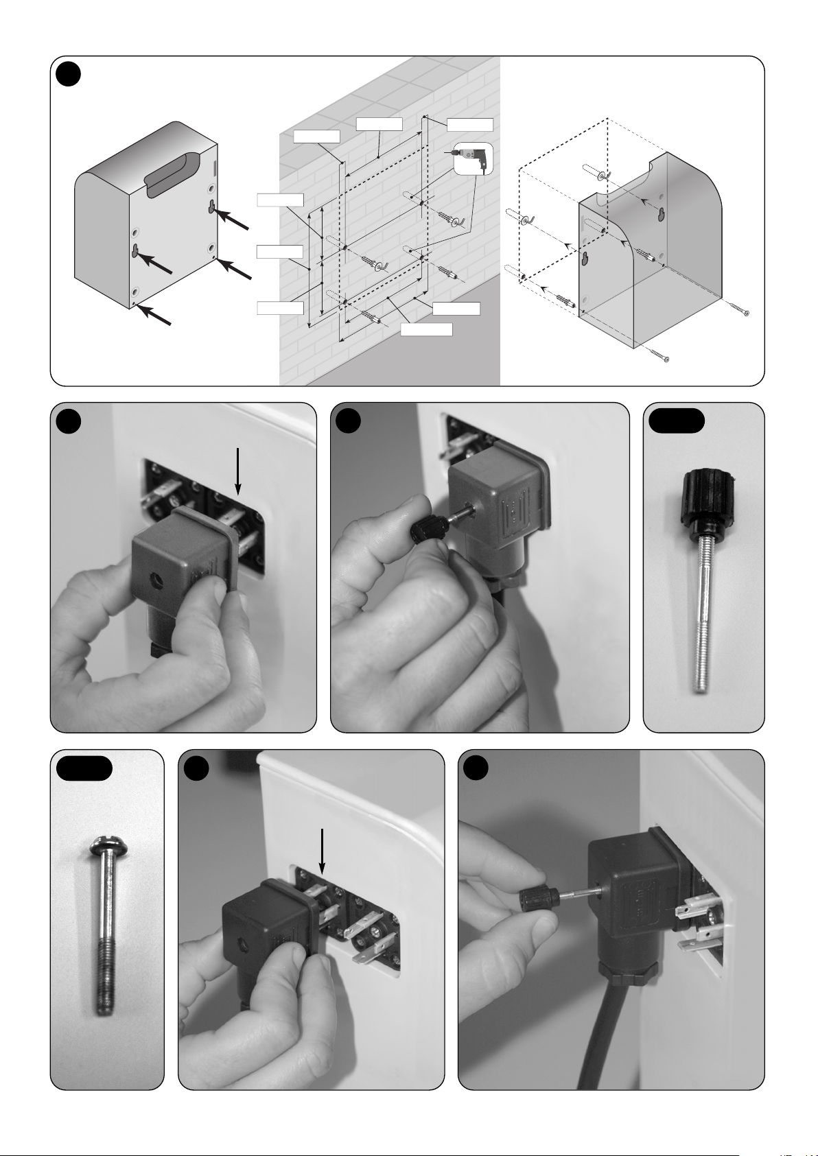
XII
205 mm
13 mm
13 mm
256 mm
128 mm
122 mm
230 mm
208 mm
IN
OUT
13
14
15
17
18
16-a
16-b


IST256R01.4862 – Rev. 00 – 26-03-2010
Nice Turkey
Kadikoy Istanbul Turkey
Ph. +90.216.456.34.97
Fax +90.216.455.78.29
info@tr.niceforyou.com
Nice UK
Sutton in Ashfield
United Kingdom
Ph. +44.16.23.55.80.86
Fax +44.16.23.55.05.49
info@uk.niceforyou.com
Nice Australia
Wetherill Park Australia
Ph. +61.(0)2.96.04.25.70
Fax +61.(0)2.96.04.25.73
info@au.niceforyou.com
Nice China
Shanghai P. R. China
Ph. +86.21.575.701.46/45
Fax +86.21.575.701.44
info@cn.niceforyou.com
Nice USA
Jacksonville Florida USA
Ph. +1.904.786.7133
Fax +1.904.786.7640
info@us.niceforyou.com
www.niceforyou.com
Headquarters
Nice SpA
Oderzo TV Italia
Ph. +39.0422.85.38.38
Fax +39.0422.85.35.85
info@niceforyou.com
Nice in Italy
Nice Padova
Sarmeola di Rubano PD Italia
Ph. +39.049.89.78.93.2
Fax +39.049.89.73.85.2
infopd@niceforyou.com
Nice Roma
Roma RM Italia
Ph. +39.06.72.67.17.61
Fax +39.06.72.67.55.20
inforoma@niceforyou.com
Nice Worldwide
Nice France
Buchelay France
Ph. +33.(0)1.30.33.95.95
Fax +33.(0)1.30.33.95.96
info@fr.niceforyou.com
Nice France Sud
Aubagne France
Ph. +33.(0)4.42.62.42.52
Fax. +33.(0)4.42.62.42.50
infomarseille@fr.niceforyou.com
Nice France Rhône Alpes
Decines Charpieu France
Ph. +33.(0)4.78.26.56.53
Fax +33.(0)4.78.26.57.53
infolyon@fr.niceforyou.com
Nice Belgium
Leuven (Heverlee) Belgium
Ph. +32.(0)16.38.69.00
Fax +32.(0)16.38.69.01
info@be.niceforyou.com
Nice Deutschland
Gelnhausen Deutschland
Ph. +49.(0)6051.91.520
Fax +49.(0)6051.91.52.119
info@de.niceforyou.com
Nice España Madrid
Mostoles Madrid España
Ph. +34.(0)9.16.16.33.00
Fax +34.(0)9.16.16.30.10
info@es.niceforyou.com
Nice España Barcelona
Sant Quirze del Valles
Barcelona España
Ph. +34.(0)9.37.84.77.75
Fax +34.(0)9.37.84.77.72
info@es.niceforyou.com
Nice Polska
Pruszków Polska
Ph. +48.(022).759.40.00
Fax +48.(022).759.40.22
info@pl.niceforyou.com
Nice Portugal
Mem Martins Portugal
Ph. +351.21.922.82.10
Fax +351.21.922.82.19
info@pt.niceforyou.com
Nice Romania
Cluj Napoca Romania
Ph./Fax +40.(0)264.453.127
info@ro.niceforyou.com
 Loading...