


Neomat T
Tubular motor
EN - Instructions and warnings for installation and use
IT - Istruzioni ed avvertenze per l’installazione e l’uso
FR - Instructions et avertissements pour l’installation et l’utilisation
ES - Instrucciones y advertencias para la instalación y el uso
DE - Installierungs-und Gebrauchsanleitungen und Hinweise
PL - Instrukcje i ostrzeżenia do instalacji i użytkowania
NL - Aanwijzingen en aanbevelingen voor installatie en gebruik


English – 1
EN
ENGLISH
original instructions
CAUTION! - The present manual contains important
safety instructions for the INSTALLATION and USE
of the product; save these instructions for future
use.
CAUTION! - Incorrect installation could cause serious
injury. For this reason, all installation instructions
contained in the present manual should be carefully
followed during the working operations.
CAUTION! - Follow these personal safety instructions
very carefully.
• The motors in the series NEOMAT-T, on versions NEOMAT-MT with Ø45mm and NEOMAT-LT with Ø58mm,
are designed for the automation of sun awnings with
casings; any other use is considered improper and is
prohibited!
• These motors are intended for residential use; maximum
continuous operating time is 4 minutes.
• When selecting the motor based on the application re quirements, the nominal torque and operating time
shown in the rating plate must be considered.
• The minimum diameter of the tube on which the motor
can be installed is 52 mm for NEOMAT-MT with torque
up to 35Nm, 60 mm for NEOMAT-MT with torque over
35 Nm and 70 mm for NEOMAT-LT.
• The motor must be installed by qualified technicians in
compliance with current safety regulations.
• All unnecessary electrical cables must be removed be fore installation; all mechanisms not required for mo torized operation must be disabled.
• If the motor is installed at a height below 2.5 m, all moving parts of the motor must be protected.
• For awning applications, the horizontal clearance be -
Safety measures
and warnings
tween the fully open awning and any stationary object
must be at least 0.4 m.
• The PVC power supply cable supplied with NEOMAT-T
motors is ideal for internal installation; an insulated tube
must be used to protect the cables when installed outside, or the specific S05RN-F type cable can be re que sted.
• The tubular motor must not be subjected to crushing,
impacts, falls or contact with any kind of liquid. Do not
perforate or drive screws into any part of the tubular
motor; see fig. 1.
• The control switch must be fixed in an easily visible location but away from moving parts and at a height no less
than 1.5 m.
• Do not modify any components unless such action is
specified in these instructions. Operations of this kind
are likely to lead to malfunctions. NICE disclaims any liability for damage resulting from modified products.
• For maintenance and repairs contact a qualified technician.
• When the roller shutter or awning is in movement, make
sure that there are no persons within the movement
range.
• Do not activate the awning if work is being carried out
close by, for example: window cleaning; in case of automatic control, disconnect the power supply as well.
• Do not let children play with the fixed control device and
keep the remote controls out of their reach.
• Check the balancing springs (if any) and the wear of
cables at frequent intervals.
CAUTION! - The climatic sensors in the series Volo and
Nemo are not to be considered safety devices that eliminate faults on the awning caused by heavy rain or strong
winds (in fact a simple power failure would make automatic movement of the awning impossible). The climatic
sensors should be considered part of an automation
used to safeguard the awning and to facilitate use.
Nice declines all liability for material damage caused by
atmospheric agents not detected by the sensors.
CAUTION! - If the slope of the awning is less than 25% or
less than the value recommended by the manufacturer it
should be retracted to avoid water pockets when it rains.
CAUTION! - The rolling shutter could be damaged if used
when ice has formed.
CAUTION! - Some programming phases use the mechan-
ical stops of the awning roll to stop motor travel; for this
reason it is essential to select the motor with the torque
most suited to the characteristics of the awning roll, considering the effective force, and avoiding the use of
excessively powerful motors.
The NEOMAT-T series motors, versions NEOMAT-MT Ø45
mm and NEOMAT-LT Ø58 mm, are electric motors equip ped with RPM reduction and terminating at one end with a
shaft on which the driving wheels can be mounted (see fig.
2). The motor is installed by inserting it in the awning tube;
it can move the awning roll for awning ascent or descent.
The control unit incorporated in the motor also has a high
precision electronic limit switch system that can constantly
detect the position of the rolling shutter.
The movement limits, awning open and awning closed (as
well as intermediate positions), can be programmed and
the awning automatically stops when these positions are
reached. The electronic limit switch can also compensate
for possible stretching of the fabric (“CAT” function) thereby
guaranteeing the perfect closure of the box and avoid sagging when opened.
To avoid excessive tensioning of the fabric when the
awning is completely closed, the motors in the series NEOMAT-T are fitted with a torque reduction function (“RDC”)
which reduces motor torque by approx. 50% shortly before
closure. This function can be disabled via a transmitter (see
4.3.2.) or by means of the special programming units TTP
and OTT-View which enable selection of the reduction on 3
levels: to approx. 50, 40 or 30% of the torque.
The CAT and RDC functions have been especially studied
to simulate the careful and meticulous behaviour of a person who opens and closes the awning manually.
The NEOMAT-T series motors incorporate a radio receiver
operating at a frequency of 433.92 MHz, with rolling code
technology that guarantees high levels of security. It is possible to memorize up to 14 transmitters for each motor in
the ERGO, PLANO and NICEWAY series; see fig. 3; that
allow the remote control of the motors, or 3 wind and sun
radio sensors “VOLO S RADIO” or “NEMO” which control
the motor depending on the weather conditions.
The programming of the limit switches and additional func-
1
Product description

2 – English
EN
tions can be done directly from the transmitters, with
beeps that sound to guide users through the various phases. It is also possible to control the motors via an external
button (using the Step-by-Step function) or “TTBUS” Bus.
Instead of the Step-by-Step button, a special F210S photocell can be connected on the TTBUS that detects possible obstacles preventing the lowering manoeuvre; see the
F210S photocell instructions for further information.
Optional wind, sun and rain sensors can be connected to
the weather sensors input that automatically activate the
motor when the weather conditions require.
The NEOMAT-T motors can be programmed with particular
functions to resolve specific problems (fig. A):
– FRT: this function allows to retract the fabric by a programmable measurement after the awning has been completely opened, thereby eliminating the unsightly sagging of
the fabric when the awning is open. For further information
see table A10.
– FTC: this function allows to motorise awnings that are kept
taught by means of an automatic hooking mechanism such
as arbour awnings. For further information see table A11.
CAUTION! - Incorrect installation could cause serious
injury.
Proceed as follows to prepare the motor (see fig. 4 - 5 - 6):
01. Position the limit switch crown (E) on the motor (A)
until it fits into the corresponding limit switch ring (F);
make sure that the two grooves match. Push it into
position as shown in fig. 5-(1).
02. Mount the drive wheel (D) on the motor shaft.
03. On NEOMAT-MT fasten the drive wheel with the snap
ring. On NEOMAT-LT fasten the drive wheel with the
M12 nut and washer.
04. Fit the assembled motor into the winding roller until
the crown (E) is fully inserted. Fasten the drive wheel
(D) to the winding roller using the M4x10 screw, so as
to prevent the motor from slipping or sliding axially
(fig. 6).
05. Finally, secure the motor head to the special support (C)
with the spacer (if any), using the clips or split pin (B).
2
Installation
2.1 - Electrical connections
CAUTION! - For motor connections, an omnipolar dis-
connecting device with a 3-mm minimum distance
between contacts must be provided for disconnection from the mains power supply (disconnecting
switch or plug and socket, etc.).
CAUTION! - Carefully follow all the connection instruc-
tions, if you have any doubts do not make experiments but consult the relevant technical specifications sheets which are also available on the web site
www.niceforyou.com. An incorrect connection may
be dangerous and cause damage to the system.
The cable used for the electrical connections of the NEOMAT-MT and NEOMAT-LT motors has 6 wires; 3 of the
wires (yellow tag) are for the mains power supply and 3
wires (violet tag) are for the command signals.
To make the electrical connections see fig. B. The connection devices are not supplied with the product.
2.1.1 - Mains power supply (Brown + Blue +
Yellow/Green)
The mains power supply must be connected to the following wires: Brown (Phase); Blue (Neutral) and Yellow/Green
(Earth). CAUTION! - Do not connect the mains power
supply (230V or 120V) to the other wires.
2.1.2 - “Step-by-Step” input (White + Black/White)
To manually command the automation system, a simple
button can be connected between the White wire (Stepby-Step input) and the Black/White wire (Common).The
operating method follows the sequence: up-stop-downstop.
If the button is kept pressed for more than 3 seconds (but
less than 10) an up manoeuvre is always carried out (corresponding to the ▲ button on the transmitters). If the button
is kept pressed for more than 10 seconds a down ma noeuvre is always carried out (corresponding to the, ▼ button). This function can be used to “synchronise” multiple
mo tors to carry out the same manoeuvre, regardless of
their operating status.
2.1.3 - “TTBUS” input (White + Black/White)
“TTBUS” is a Bus that was developed to control individually motors or control units, up to 100 devices by simply con-
necting them in parallel with just 2 wires. Further information is contained in the instructions for the remote controls
via “TTBUS”.
The TTP, TTI and O-ViewTT programmers can be connected to the TTBUS input making the system management
and programming operations easier; for further information, consult the related manuals.
2.1.4 - “F210S Photocell” input (White +
Black/White)
The specific F210S photocell can be connected to the
“F120S photocell” input that detects possible obstacles
preventing the lowering manoeuvre. See the F210S photocell instructions manual for further information concerning
connections.
CAUTION! - The Step-by-Step, TTBUS and F210S
inputs are alternative one to the other because each
uses the same White + Black/White wires, therefore
one type of input can be used at a time.
2.1.5 - Weather sensors (Black/White +
Orange/White)
A simple wind sensor (anemometer) or a wind-sun-rain
special sensor can be connected to the “Weather sensors”
input between the Common and the Weather sensors
input.
If wind sensors are used, up to 5 motors or control units
can be connected to the same sensor, using a parallel connection (observe signal polarity).
Caution! - Though possible, avoid connecting a single sun
sensor to more than one motor. In fact if the thresholds of
the various motors are set to the same value, each motor
makes its own measurement and the automatic movements of the awnings will not be simultaneous.
To move multiple motors simultaneously, sensors with their
own specific threshold setting are required, such as the
models Volo ST, Volo S Radio and Nemo.
2.2 - Cable output direction (fig. C)
(For model NEOMAT-LT only) – If it is necessary to chan -
ge the cable output direction, simply: 01. Pull the protection outwards. 02. Bend the cable in the required direction.
03. Introduce the protection, making sure that it is secure-
ly pushed into its location.

English – 3
EN
Awning completely
closed (Pos. “0”)
Awning open (Pos.”1”)
Intermediate
position (“I”)
Position for start of torque reduction (RDC) in the
closing manoeuvre (non programmable position)
Position “2” for
“FRT” function
Release position
“S” for awnings
that are kept
taught by means
of an automatic
hooking mechanism
“0”
“A”
“2”
“1”
“S”
E
2.3 - Power supply cable and connector
(For model NEOMAT-MT only) – The information in this
chapter is aimed exclusively at Service centre technical
personnel.
CAUTION! - If the power cord is damaged it must be
replaced with an identical type supplied by the manufacturer or an authorised customer service centre.
If the motor must be disconnected from the power cable,
proceed as follows (fig. D): a) - Turn the ring nut until the bevel coincides with one of the connecting teeth, and then disconnect. b) - Repeat the same operation for the other tooth.
c) - Bend the cable inwards and remove the protection by
turning it carefully outwards. d) - Pull out the connector.
The NEOMAT tubular motors feature an electronic limit
switch system, the electronic control unit interrupts the
movement when the awning reaches the set opening and
closing positions. These positions must be programmed
into the memory after the motor has been installed and the
awning mounted.
(fig. E) The motor can still be controlled even if these two
positions, “0” (awning closed) and “1” (awning open), have
not yet been memorised, however, the movement in this
case will be hold-to-run.
The following positions can also be programmed:
• Intermediate position “I” for partial awning opening. This
po sition can be programmed later if required.
• Position “2” necessary for the “FRT” function that keeps
the fabric taught when the awning is fully open.
• The “FTC” function to automate awnings with an auto-
matic hooking mechanism.
3
Adjustments

4 – English
EN
The programming phase is divided into 3 parts:
1. Memorisation of the transmitters
2. Programming of positions “0” and “1”
3. Optional programming
The memorisation phases must be performed as indicated in table A1 to ensure that a
transmitter can control a NEOMAT-T motor.
WARNING:
• All the memorization sequences are timed, that is, they must be completed
within the programmed time limits.
• For transmitters with multiple “groups”, choose the transmitter group the motor must be
associated with before proceeding with the memorization phase.
• Programming via radio may be done on all the receivers within the range of the transmitter; therefore, only the one involved in the operation should be kept switched on.
It is possible to check if the motor already has transmitters memorized; this is done by
checking the number of beeps when the motor is switched on:
- 2 long beeps = No memorized transmitter.
- 2 short beeps = There are already transmitters memorized.
4.1 - Programming the transmitters
––––––––––––––––––––––––––––––––––––––––––––––––––––––––––––––––––––––––––––
Table “A1” - Memorizing the first transmitter (in Mode I)
––––––––––––––––––––––––––––––––––––––––––––––––––––––––––––––––––––––––––––
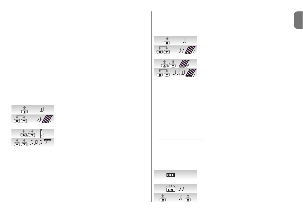
01. Connect the motor to the power supply, 2 long beeps
will be heard immediately.
02. Within 5 seconds press and hold button ■ of the transmitter to be memorized (for approx. 3 seconds).
03. Release button ■ when you hear the first of the 3 beeps
confirming memorization.
See table A2 for the memorization of additional transmitters.
When one or more transmitters have already been memorized, others may be enabled as
shown in table A2.
––––––––––––––––––––––––––––––––––––––––––––––––––––––––––––––––––––––––––––
Table “A2” - Memorizing additional transmitters (Mode I)
––––––––––––––––––––––––––––––––––––––––––––––––––––––––––––––––––––––––––––
01. Press and hold down button ■ of the new transmitter (for
approx. 5 seconds) until you hear a beep then release it.
4
Programming
02. Press button ■ of a previously memorized transmitter
slowly 3 times.
03. Press button ■ on the new transmitter again. Release
button ■ when you hear the first of 3 beeps, signalling
that memorization has been carried out.
Note: If the memory is full (14 transmitters), 6 beeps will indicate that the transmitter cannot be memorized.
4.2 - Programming of positions “0” and “1”
A remote control memorised in Mode I must be used to program the positions. The
manoeuvres will remain hold-to-run until positions “0” and “1” have been memorised in the
control unit. To begin with, the direction of the motor is not defined but after point 1 in table
A3 has been completed the direction of the motor is automatically assigned to the remote
control buttons.
Follow the procedure in table A3 to program the “0” and “1” positions:
––––––––––––––––––––––––––––––––––––––––––––––––––––––––––––––––––––––––––––
Table “A3” - Programming of positions “0” and “1”
––––––––––––––––––––––––––––––––––––––––––––––––––––––––––––––––––––––––––––
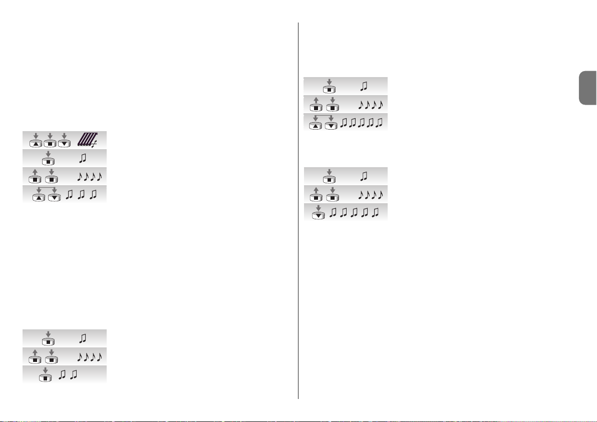
01. Press and hold buttons ▲ or ▼ of a memorised remote
control until the awning is fully closed and the motor
automatically stops.
02. Press and hold button ▼ that lowers the awning.
03. Release button ▼ when the awning is in the desired
position (“1”). If necessary use the ▼ and ▲ buttons to
adjust the position.
04. Press and hold button ■ of the transmitter until you hear
a beep (after about 5 seconds) then release it.
05. Release and press again button 5 for another 5 seconds
until ■ rapid beeps are heard.
06. Press button ▼ until 3 beeps are heard and a short up
and down movement occurs indicating that the position
has been memorised.
4.3 - Optional programming
Optional programming is only possible after positions “0” and “1” have been programmed.
4.3.1 - Memorisation of the intermediate position “I”
When an intermediate position “I” is memorised the awning can be manoeuvred into the “I”
3s...
5s...
x 3
new
old
new
5s...
5s...

English – 5
EN
position by pressing the ▲ and ▼ buttons of the transmitter together.
Follow the procedure shown in table A4 to memorise the intermediate position:
––––––––––––––––––––––––––––––––––––––––––––––––––––––––––––––––––––––––––––
Table “A4” - Programming of the intermediate position “I”
––––––––––––––––––––––––––––––––––––––––––––––––––––––––––––––––––––––––––––
01. Using buttons ▲ ■ ▼ of a remote control, move the
awning into the “I” position to be memorised.
02. Press and hold down button ■ until you hear a beep
(after about 5 seconds).
03. Release and press again button ■ for another 5 seconds
until 4 rapid beeps are heard.
04. Press buttons ▼ and ▲ together until 3 beeps are heard,
indicating that the position has been memorised.
4.3.2 - Deactivation or reactivation of Torque Reduction on closing (RDC)
Torque reduction is a function that reduces the traction torque by approx. 50% shortly
before complete closure of the awning against the casing, to avoid excessive tensioning of
the fabric. This function is activated automatically after programming positions 0 and 1
(programming is always at maximum force) but can be deactivated (or re-activated) if
required.
Note - automatic activation of the RDC function does not occur if position programming is
performed using programmers TTP, TTI and O-ViewTT; in these cases the function can be
activated manually as required.
––––––––––––––––––––––––––––––––––––––––––––––––––––––––––––––––––––––––––––
Table “A5” - Deactivation or reactivation of Torque Reduction (RDC)
––––––––––––––––––––––––––––––––––––––––––––––––––––––––––––––––––––––––––––
01. Press and hold down button ■ of a previously memorized
transmitter until you hear a beep (after about 5 seconds).
02. Release and press again button ■ for another 5 seconds
until 4 rapid beeps are heard.
03. Press ■ until the signal beeps are emitted: 3 Beeps indi-
cate RDC active (closure at reduced torque); 5 Beeps
indicate RDC not active (closure at maximum torque).
4.3.3 - Deleting positions
To modify the previously memorised positions, they must firstly be cancelled and then the
new positions programmed again.
––––––––––––––––––––––––––––––––––––––––––––––––––––––––––––––––––––––––––––
Table “A6” - Cancellation of the intermediate position “I”
––––––––––––––––––––––––––––––––––––––––––––––––––––––––––––––––––––––––––––
01. Press and hold down button ■ of a previously memorized
transmitter until you hear a beep (after about 5 seconds).
02. Release and press again button ■ for another 5 seconds
until 4 rapid beeps are heard.
03. Press buttons ▼ and ▲ together until 5 beeps are heard, in -
di cating that the intermediate position has been cancelled.
––––––––––––––––––––––––––––––––––––––––––––––––––––––––––––––––––––––––––––
Table “A7” - Cancellation of positions “0” and “1”
––––––––––––––––––––––––––––––––––––––––––––––––––––––––––––––––––––––––––––
01. Press and hold down button ■ of a previously memorized
transmitter until you hear a beep (after about 5 seconds).
02. Release and press again button ■ for another 5 seconds
until 4 rapid beeps are heard.
03. Press button ▼ until 5 beeps signal that positions “0”
and “1” have been cancelled.
WARNING: After deleting positions “0” and “1” the awning moves in hold-to-run mode
and the new positions need to be memorised.
Note: the intermediate positions “I” and the RDC function that are programmed are not
cancelled. If you wish to cancel everything (including the codes of the transmitters), refer to
table “A14”.
4.3.4 - Programming of the “wind” weather sensor level
If a "VOLO" or "VOLO S" wind sensor is connected to the “sensors” input, the wind protection is activated that automatically retracts the awning when the wind exceeds the programmed level. If the level is exceeded for more than 3 seconds, a command that is the
same as the ▲ button is activated and any other movement is blocked until the wind level
returns below the programmed level for more than 1 minute. There is a choice of 5 different activation levels: 1=5Km/h, 2=10Km/h, 3=15Km/h, 4=30Km/h and 5=45Km/h. (the
level is factory set at No.3).
If using the sensor “VOLO ST” or radio sensors Volo S Radio and Nemo, the wind trip
thresholds are programmed directly on the sensor (see relative instructions).
To modified the programmed level:
––––––––––––––––––––––––––––––––––––––––––––––––––––––––––––––––––––––––––––
Table “A9” - Changing the activation level of the “wind” protection
––––––––––––––––––––––––––––––––––––––––––––––––––––––––––––––––––––––––––––
01. Press and hold down button ■ of a previously memo-
rized transmitter until you hear a beep (after about 5 seconds) then release it.
02. Slowly press button ▲ the same number of times (1, 2,
3, 4 or 5) as the desired level.
5s...
5s...
5s...
5s...
5s...
5s...
(...)
5s...
5s...
5s...
x 1 = 5 Km/h
x 2 = 10 Km/h
x 3 = 15 Km/h
x 4 = 30 Km/h
x 5 = 45 Km/h

6 – English
EN
03. After a few moments you will hear a number of beeps
equal to the required level.
04. Press and release button ■ to confirm.
If at point 3 you don't here the number of beeps equal to the desired level, simply do not
press anymore buttons and wait a few seconds for it to finish without changing the level.
4.3.5 - Programming of the “sun” weather sensor level
If a "VOLO S" sun sensor is connected to the “sensors” input, the sun automation is activated that automatically lowers the awning when the “sun” exceeds the programmed level. If the level is exceeded for more than 2 minutes, a command that is the same as the ▼
button is activated and if the sun drops below the programmed level for 15 minutes, a
command is activated that is the same as button ▲.
There is a choice of 5 different “sun” activation levels: 1=5Klux, 2=10Klux, 3=15Klux,
4=30Klux and 5=45Klux (the level is factory set at No. 3).
––––––––––––––––––––––––––––––––––––––––––––––––––––––––––––––––––––––––––––
Table “A10” - Changing the activation level of the “sun” automation
––––––––––––––––––––––––––––––––––––––––––––––––––––––––––––––––––––––––––––
If using the sensor “VOLO ST” or radio sensors Volo S Radio and Nemo, the sun trip
thresholds are programmed directly on the sensor (see relative instructions).
01. Press and hold down button ■ of a previously memo-
rized transmitter until you hear a beep (after about 5 seconds) then release it.
02. Slowly press button ▼ the same number of times (1, 2,
3, 4 or 5) as the desired level.
03. After a few moments you will hear a number of beeps
equal to the required level.
04. Press and release button ■ to confirm.
If at point 3 you don’t here the number of beeps equal to the desired level, simply do not
press anymore buttons and wait a few seconds for it to finish without changing the level.
4.3.6 - hanging the direction of movement in the event of rain
If using a rain sensor Nemo WSRT; when the sensor detects the presence of rain, it sends
the data to the motors and movement is activated in the programmed direction (the factory setting is “up”).
To modify the rain trip direction:
01. Press and hold ■ on a previously memorised transmitter until you hear a beep (after
approx. 5 seconds); then release.
02. Slowly press the same key ■ three more times.
03. Press the required direction key (up or down); the motor then emits 3 beeps = new
direction memorised.
Automatic movements generated by the “sun” sensor can be deactivated by a “Sun OFF”
command sent from a transmitter with this function (Ergo 4, Plano 4, WM004G) and can
be re-activated by means of a “Sun ON” command.
The automatic movements generated by the “sun” sensor can be accompanied at any
time by means of commands sent by the user via a normal transmitter; the latter have pri
-
ority over the “sun” sensor commands, as described in the following example: if the
awning is in position “1” (reached automatically when the “sun” threshold is exceeded) and
shortly afterwards the user sends a command for return of the awning to position “0”, in
the next interval, even if the system continues to read values exceeding the “sun” threshold, the awning is not moved
(remaining in the position set by the user).
The “automatic cycle” interrupted by the manual command is restored when the brightness level falls below the threshold (normally at dusk).
4.3.7 - Programming of the “FRT” function
After having programmed positions “0” and “1”, position “2” can be programmed that activates the retraction function FRT of the fabric.
Follow the indications in table “A11” to program position “2”.
––––––––––––––––––––––––––––––––––––––––––––––––––––––––––––––––––––––––––––
Table “A11” - Programming position “2”
––––––––––––––––––––––––––––––––––––––––––––––––––––––––––––––––––––––––––––
01. Press and hold down button ■ of a previously memorized
transmitter until you hear a beep (after about 5 seconds).
02. Press and hold buttons ■▼for another 5 seconds until 2
rapid beeps are heard. At this point the awning automatically
moves to the position of the lower limit switch (position “1”).
03. Use buttons ▼ and ▲ within 5 seconds to position the
awning in the desired retraction position.
04. Confirm the position with button ■ of the transmitter
within 5 seconds until 3 beeps are heard. Afterwards the
awning will move to the lower programmed limit switch
position (position “1”).
5s...
x 1 = 5 Km/h
x 2 = 10 Km/h
x 3 = 15 Km/h
x 4 = 30 Km/h
x 5 = 45 Km/h
5s...
5s...
x 1 = 5 Klux
x 2 = 10 Klux
x 3 = 15 Klux
x 4 = 30 Klux
x 5 = 45 Klux
x 1 = 5 Klux
x 2 = 10 Klux
x 3 = 15 Klux
x 4 = 30 Klux
x 5 = 45 Klux
English – 7
EN
Note: if the programming described in point 4 is not confirmed the modifications are aborted and the previous programming is maintained.
If after having programmed this function you wish to eliminate it, the procedure in table A13
must be followed, omitting step 3 which would modify position “1”.
When position “2” is programmed, the electronic control unit automatically calculates the
difference between positions “2” and “1”, so that each time a lower command is given, the
awning lowers to the greater of the two positions and then retrieves the fabric until arriving
to the lesser of the two positions.
4.3.8 - Programming of the “FTC” function
After having programmed positions “0” and “1”, position “S” can be programmed that activates the “FTC” function for the automation of awnings with an automatic hooking mechanism. Until the mechanism is working correctly, position “1” must be programmed a few
centimetres after the hooking point so that hooking occurs when retracting from point “1”,
and position “S” is programmed a few centimetres after the release point so that the
ascent from point “S” is performed freely.
Follow the procedure indicated in table “12” to program position “S”:
––––––––––––––––––––––––––––––––––––––––––––––––––––––––––––––––––––––––––––
Table “A12” - Programming the release position “S”
––––––––––––––––––––––––––––––––––––––––––––––––––––––––––––––––––––––––––––
01. Press and hold down button ■ of a previously memorized
transmitter until you hear a beep (after about 5 seconds).
02. Press and hold buttons ■▼for another 5 seconds until
2 rapid beeps are heard. At this point the awning automatically moves to position “1”.
03. Use buttons ▼ and ▲ within 5 seconds to position the
awning in the release position “S” (below position “1”).
04. Confirm the position by pressing buttons ▼ and ▲ of the
transmitter together within 5 seconds until 3 beeps are
heard. At this point the awning will automatically move to
position “0”.
Note: if the programming described in point 4 is not confirmed the modifications are aborted and the previous programming is maintained. If after having programmed this function
you wish to eliminate it, the procedure in table A13 must be followed, omitting step 3 which
would modify position “1”.
4.3.9 - Modifying position “1”
Follow the procedure indicated in table “A13” to modify position “1”:
––––––––––––––––––––––––––––––––––––––––––––––––––––––––––––––––––––––––––––
Table “A13” - Modifying position “1”
––––––––––––––––––––––––––––––––––––––––––––––––––––––––––––––––––––––––––––
01. Press and hold down button ■ of a previously memorized
transmitter until you hear a beep (after about 5 seconds).
02. Press and hold buttons ■▼for another 5 seconds until
2 rapid beeps are heard. At this point the awning automatically moves to the position “1”.
03. Use buttons ▼ and ▲ within 5 seconds to reposition the
awning in the new position to be programmed.
04. Confirm the position by pressing buttons ■▼of the
transmitter together within 5 seconds until 3 beeps are
heard and a short up and down movement is performed.
Note: if the programming described in point 4 is not confirmed the modifications are aborted and the previous programming is maintained.
By modifying position “1” the "FRT" and "FTC" functions are cancelled.
4.4 - Memory deletion
If you need to delete all the transmitter and the programmed operations, carry out the procedure shown in table A14.
The memory can be deleted
:
• with a non-memorized transmitter starting from point A.
• with a previously memorized transmitter starting from point No. 1.
The following can be deleted
:
• only the memorized transmitters, finishing at point No. 4
• all data (transmitters, sensor level, TTBUS address, etc.), completing the procedure
until point 6.
––––––––––––––––––––––––––––––––––––––––––––––––––––––––––––––––––––––––––––
Table “A14” - Memory deletion
––––––––––––––––––––––––––––––––––––––––––––––––––––––––––––––––––––––––––––
A. Switch the motor off, activate the Step-by-Step input (by
connecting the White cable with the White/Black one)
and keep it active until the end of the procedure.
B. Power the motor and wait for the initial beeps.
01. Press and hold down button ■ on a transmitter (about 5
seconds) until you hear a beep; then release it.
5s...
5s...
5s...
5s...
1
S
P. P.
5s...

8 – English
EN
Table “A15”
02. Hold down the ▲ button on the transmitter until you hear
3 beeps; release the ▲ button exactly during the third
beep.
03. Hold down button ■ on the transmitter until you hear 3
beeps; release button ■ exactly during the third beep.
04. Hold down the ▼ button on the transmitter until you hear
3 beeps; release the ▼ button exactly during the third
beep.
05. To cancel everything: press both ▲ and ▼ within 2 sec-
onds.
06. Cancellation is confirmed by releasing buttons ▲ and ▼
on the first of the 5 beeps.
The NEOMAT-T motors recognise other ERGO, PLANO, NICEWAY, VOLO S RADIO and
NEMO series transmitters (see chapter 5.1 “Available transmitters”).
A particular command can also be associated to each transmitter button by means of a
specific memorization procedure (see chapter 5.2 “Transmitter programming in Mode I and
Mode II”).
Warning: use transmitters that have been memorised in Mode I only for programming.
5.1 - Available transmitters
Table A15 indicates the transmitters that can be used with the related coding.
––––––––––––––––––––––––––––––––––––––––––––––––––––––––––––––––––––––––––––
Table “A15” - Transmitters
• ERGO1 - ERGO4 - ERGO6 • PLANO1 - PLANO4 - PLANO6 - PLANO TIME • VOLO S
RADIO • NEMO • NICEWAY (the whole series) • FLO1R - FLO2R - FLO4R • VERY VR •
––––––––––––––––––––––––––––––––––––––––––––––––––––––––––––––––––––––––––––
5.2 - Memorizing the transmitters in Mode I and Mode II
Tables “A1” and “A2” describe the memorization of the transmitters in “Mode I” where a
specific command is assigned to each button: button ▲ (1) = “Up”; button ■ (2) = “Stop”;
button ▼ (3) = “Down”.
5
Additional information
The transmitters can also be memorized on “Mode II”, which allows greater flexibility in the
use of the transmitter buttons. Transmitters can be memorized both in Mode I and Mode II
on the same NEOMAT-T motor.
5.2.1 - Mode I
The command associated to the transmitter buttons is fixed in Mode I: button ▲ (1) = “Up”;
button ■ (2) = “Stop”; button ▼ (3) = “Down”, another button 4 commands the “Stop”.
A single memorization phase is performed in Mode I for each transmitter and a single section is occupied in the memory. It is not important which button is pushed when memorizing in Mode I.
Memorizing and deleting the transmitters in Mode I (see Tables A1 and A2).
Button Command
Button ▲ or 1 Up
Button ■ or 2 Stop
Button ▼ or 3 Down
Button 4 Stop
5.2.2 - Mode II
One of the four possible commands can be associated to each of the transmitter buttons
in Mode II: 1 = Step-by-Step; 2 = Up-Stop; 3 = Down-Stop, 4 = Stop. A memorization
phase is performed for each button in Mode II, and each occupies a section of the memory. The button pushed is memorized during memorization in Mode II. A new memorization
is necessary if one wishes to assign another command to another button of the same
transmitter.

English – 9
EN
No. Command
1 Step-by-Step (up-stop-down-stop…),
2 Up-Stop (up-stop-up-stop…)
3 Down-Stop (down-stop-down-stop…)
4 Stop
5.2.3 - Example of Mode I and Mode II combined memorization
Group commands can be created taking opportune advantage of the Mode I and Mode II
memorizations as shown in the fig. F.
• The T1 transmitter (Ergo1) memorized in Mode I on A1 and A2 simultaneously commands the Up, Stop or Down of both A1 and A2.
• The T2 transmitter (Plano1) memorized in Mode I on A3 only, commands the Up, Stop or
Down of A3 only.
• The T3 transmitter (Planotime) memorized in Mode 1 on A4 only, commands the Up,
Stop or Down of A4 only.
• The T4 transmitter (WM001C) memorized in Mode II (Step-by-Step) commands A4 only.
• The T5 transmitter (WM003G) memorized in Mode I to command A1 and A2 with group
1, A3 with group 2 and A4 with group 3; commands the Up, Stop or Down of A1 and
A2, A3 or A4.
• The T6 transmitter (Flo4R) memorized in Mode II on A4 (buttons 1 and 3) on A5 (button
2) and on A6 (button 4), commands the Up and Down of A4, or the opening of the
garage door A5 or the opening of the automatic gate A6.
WARNING:
• Some functions (positions, levels…) cannot be programmed with the transmitter memorized in Mode II as different buttons need to be pushed in this phase, such as button ■
and button ▲ for example.
• The “multiple group” commands cannot be used with a transmitter memorized in Mode II.
When one or more transmitters have already been memorized, others may be memorized
in Mode II as shown in table A16.
––––––––––––––––––––––––––––––––––––––––––––––––––––––––––––––––––––––––––––
Table “A16” - Memorizing additional transmitters in Mode II
––––––––––––––––––––––––––––––––––––––––––––––––––––––––––––––––––––––––––––
01. Press and hold down the button to be memorized of the
new transmitter (for approx. 5 seconds) until you hear a
beep; then release it.
02. Within 5 seconds push and hold the button of an old and
already memorized transmitter (approx. 5 seconds) until
2 beeps are heard; then release the button.
03. Within 5 seconds start to push the same button of the old
transmitter the same number of times equal to the re quired
command: 1=“Step-by-Step” 2=“Up” 3=“Down” 4=“Stop”.
04. After about 3 seconds the same number of beeps as the
selected command are heard.
05. Within 2 seconds push the same button of the new
transmitter.
06. Release the button when you hear the first of the 3
beeps confirming memorization.
If at point 5 the same number of beeps equal to the selected command are not heard, simply do not push any more buttons and wait a few seconds for the programming to finish
without memorizing.
Note: If the memory is full (14 transmitters), 6 beeps will indicate that the transmitter cannot be memorized.
A new transmitter can easily be memorized with the same characteristics as that of the old
one by following the procedure in table A17. The “new” transmitter will inherit the characteristics of the old one, i.e. if the old transmitter was memorized in Mode 1, the new one
will also function in Mode 1, if the old transmitter was memorized in Mode II then the button of the new transmitter will be associated to the same command as that of the old one.
––––––––––––––––––––––––––––––––––––––––––––––––––––––––––––––––––––––––––––
Table “A17” - Memorizing other transmitters
––––––––––––––––––––––––––––––––––––––––––––––––––––––––––––––––––––––––––––
01. Press and hold down the button to be memorized of the
new transmitter (for approx. 3 seconds) then release it.
02. Press and hold down the button to be memorized of the
old transmitter (for approx. 3 seconds) then release it.
03. Press and hold down the button to be memorized of the
new transmitter (for approx. 3 seconds) then release it.
04. Press and hold down the button to be memorized of the
old transmitter (for approx. 3 seconds) then release it.
05. The memorization of the new transmitter is confirmed
with 3 beeps.
Note: If the memory is full (14 transmitters), 6 beeps will indicate that the transmitter cannot be memorized.
5s.
new
5s.
old
1- 4
new
1- 43s.
new
>3s.
new
>3s.
old
>3s.
new
>3s.
old

10 – English
EN
This product constitutes an integral part of the automation system, therefore it must
be disposed of along with it.
As in installation, also at the end of product lifetime, the disassembly and scrapping operations must be performed by qualified personnel.
This product is made up of different types of material, some of which can be recycled while
others must be disposed of. Seek information on the recycling and disposal systems
envisaged by the local regulations in your area for this product category.
Caution! – some parts of the product may contain pollutant or hazardous substances
which, if disposed of into the environment, may cause serious damage to the environment
or physical health.
As indicated by the symbol on the left, disposal of this product in domestic
waste is strictly prohibited. Separate the waste into categories for disposal,
according to the methods envisaged by current legislation in your area, or
return the product to the retailer when purchasing a new version.
Caution! – Local legislation may envisage serious fines in the event of abusive
disposal of this product.
❏ When the motor is switched on, no beep is emitted and the Step-by-Step
input does not command any movement.
Make sure the motor is powered at the correct mains voltage; if the power supply is correct there is probably a serious fault and the motor needs to be repaired by the customer
service department.
❏ The motor does not move after a command is given.
• If it has been working up until then, it may be that the thermal protection device has cutin, therefore wait a few minutes for the motor to cool.
• Check if the “Step-by-Step” input is functioning by joining the White and Black/White
wires together for a second.
• Make sure that there is at least one memorized transmitter, checking that the motor
emits short beeps when switched on.
• Make sure that the transmitter and motor are communicating, keeping button ■ (2) of a
transmitter (memorized or not) pushed for at least 5 seconds, if a beep is heard this
means that the motor is receiving the signal from the transmitter therefore go on to the
last control; otherwise perform the next control.
• Check the correct emission of the transmitter radio signals with the following empirical
test: push a button and rest the LED against the aerial of a normal household radio (ide-
7
What to do if... a short troubleshooting guide!
6
Disposal of the product
ally inexpensive) that is switched on and tuned in at 108.5 Mhz FM or as close as possible; a low sound should be heard with crackling pulses.
• Check, by slowly pushing one at a time, all of the transmitter buttons, if none of them
command a movement of the motor, this means that the transmitter is not memorized.
❏ After a radio command, 6 beeps are heard and the manoeuvre does not
start.
The radio control unit is unsynchronised, repeat the transmitter memorization process.
❏ After a command, 10 Beeps sound and then the manoeuvre begins.
The auto-diagnosis of the memorized parameters has revealed a fault (positions, TTBUS
address, wind levels are incorrect). Delete and repeat programming if necessary.
❏ When raising the motor stops before reaching the set position (pos. “0”,
pos. “I”) and then makes three attempts to start again.
This is normal: when an excessive force is detected while raising, the motor is switched off
for about 1 second and then attempts to finish the manoeuvre; check if there are obstacles
that are blocking the movement.
❏ When lowering the motor stops before reaching the set position (pos. “1”,
pos. “I”).
This is normal: when an excessive force is detected while raising, the motor is switched off;
check if there are obstacles that are blocking the movement.
❏ The motor only moves in “hold-to-run”.
If positions “0” and “1” haven't been programmed the up and down movement of the
motor occurs in hold-to-run only. Program positions “0” and “1”.
❏ The motor moves correctly for UP travel, but only in hold-to-run mode on
descent.
The self-diagnosis of the memorised parameters has detected an error in the motor's position. Activate the awning to complete an entire up travel stroke.

English – 11
EN
Technical specifications of the NEOMAT-MT and NEOMAT-LT tubular motors
• Supply Voltage and Frequency: See the technical data on the label attached to each
model
• Current and power: See the technical data on the label attached to each model
• Torque and speed: See the technical data on the label attached to each model
• Motor diameter: NEOMAT-MT = 45mm; NEOMAT-LT = 58mm
• Precision (Resolution) of the electronic limit switch: greater than 0.55° (depending
on the NEOMAT-T version)
• Precision of the stop positions: Class 2 (±5%)
• Mechanical resistance: in accordance with EN 14202
• Continual operating time: Maximum 4 minutes
• Protection class: IP 44
• Working temperature: -20 ÷ +55 °C
• Length of connection cable: 3 m
• Signal voltage (step-by-step, TTBUS…): Approx. 24 V
• Wind sensor (anemometer) levels: 5 approx. 5, 10, 15, 30 or 45 km/h (with VOLO OR
VOLO-S anemometer)
• Sun sensor levels: 5 approx. 5, 10, 15, 30 or 45 Klux (with VOLO-S)
• Length of signal cables (step-by-step, TTBUS…): max. 30m if near other cables,
otherwise 100m
• Radio receiver frequency: 433.92 MHz
• Radio receiver coding: 52 Bit rolling code FLOR and FLOR+INFO
• No. of transmitters that can be memorized: 14, including a maximum of 3 VOLO-S-
Radio climatic sensors
• Portata dei trasmettitori: Estimated 150 m in the open and 20 m inside buildings (*).
Note:
– (*) The range of the transmitters can be influenced by other devices operating in the
vicinity at the same frequency as the transmitter (for example radio headphones, alarm
systems etc.) causing interference with the receiver. In the event of strong interference,
Nice cannot provide any guarantee as regards the effective capacity of its radio devices.
– All technical characteristics refer to an ambient temperature of 20°C (± 5°C).
– Nice S.p.a. reserves the right to apply modifications to the product at any time when
deemed necessary, while maintaining the same functionalities and intended use.

12 – English
EN
CE DECLARATION OF CONFORMITY
Note - The contents of this declaration correspond to those of the last revision available of the official document,
deposited at the registered offices of Nice S.p.a., before printing of this manual. The text herein has been re-edited for
editorial purposes.
Number: 223/Neomat T Revision: 3
The undersigned, Luigi Paro, in the role of Managing Director, declares under his sole responsibility, that the product:
Manufacturer’s name: NICE s.p.a.
Adress: Via Pezza Alta, 13, Z.I. Rustignè, 31046 - Oderzo (TV) Italy
Type: Tubular gearmotor for awnings in casings with built-in control unit and radio receiver
Models: Neomat MT, Neomat LT
Accessories: Radio control series Ergo, Plano, NiceWay, VOLO-S-Radio Wind speed sensors VOLO, VOLO-S
conforms to the requirements of the EC directive:
• 1999/5/EC; DIRECTIVE 1999/5/EC OF THE EUROPEAN PARLIAMENT AND COUNCIL of 9 March 1999 regarding
radio equipment and telecommunications terminal equipment and the mutual recognition of their conformity
according to the following harmonised standards:
- Health protection: EN 50371:2002;
- Electromagnetic compatibility : EN 301 489-1 V1.8.1:2008; EN 301 489-3 V1.4.1:2002
- electrical safety: EN 60950-1:2006
- Radio range: EN 300 220-2 V2.1.2:2007
and also complies with the requirements of the following EC directives, as amended by Directive 93/68/EEC of the
European Council of 22 July 1993:
• 2006/95/EC DIRECTIVE 2006/95/EC OF THE EUROPEAN PARLIAMENT AND COUNCIL of 12 December 2006
regarding the approximation of member state legislation related to electrical material destined for use within specific voltage limits, according to the following harmonised standards: EN 60335-1:2002 + A1:2004 + A11:2004 +
A12:2006 + A2:2006 + A13:2008; EN 60335-2-97:2006 + A11:2008; EN50366:2003 + A1:2006
• 2004/108/EC DIRECTIVE 2004/108/EC OF THE EUROPEAN PARLIAMENT AND COUNCIL of 15 December 2004
regarding the approximation of member state legislation related to electromagnetic compatibility, repealing directive
89/336/EEC, according to the following standards: EN 55014-1:2006; EN 55014-2:1997 + A1:2001; EN 61000-32:2006; EN 61000-3-3:2007
Oderzo, 28.07.09
Luigi Paro
(Managing director)

Italiano – 1
IT
ITALIANO
Istruzioni originali
ATTENZIONE! - Il presente manuale contiene impor-
tanti istruzioni di sicurezza per l'INSTALLAZIONE e
l'USO del prodotto; conservare queste istruzioni.
ATTENZIONE! - L'installazione non corretta può cau-
sare gravi ferite. Per questo motivo, durante le fasi
del lavoro, si raccomanda di seguire attentamente
tutte le istruzioni di installazione contenute in questo
manuale.
ATTENZIONE! - Per la sicurezza delle persone è im -
portante rispettare queste istruzioni.
• I motori della serie NEOMAT-T, nelle versioni NEOMATMT con Ø45mm e NEOMAT-LT con Ø58mm sono destinati all’automatizzazione del movimento di tende da sole
provviste di cassonetto; ogni altro uso è improprio e
vietato!
• I motori sono progettati per uso residenziale; è previsto
un ciclo di lavoro continuo massimo di 4 minuti.
• Nella scelta del tipo di motore in funzione dell'applicazione, si dovrà considerare la coppia nominale ed il tempo
di funzionamento riportati sui dati di targa.
• Il diametro minimo del rullo avvolgitore su cui il motore
può essere installato è 52mm per NEOMAT-MT con coppie fino a 35Nm, 60mm per NEOMAT-MT con coppie
maggiori di 35Nm e 70mm per NEOMAT-LT.
• L'installazione deve essere eseguita da personale tecnico nel pieno rispetto delle norme di sicurezza.
• Prima dell'installazione devono essere allontanati tutti i
cavi elettrici non necessari; tutti i meccanismi non necessari per il funzionamento motorizzato devono essere
disattivati.
• Le parti in movimento del motore devono essere protette se questo è montato ad una altezza inferiore a 2,5m.
• Nelle tende da sole, la distanza in orizzontale tra la tenda
Avvertenze e precauzioni
per la sicurezza
completamente aperta e qualsiasi oggetto permanente
deve essere garantita ad almeno 0,4m.
• Il cavo di alimentazione in PVC in dotazione ai motori
serie NEOMAT-T li rendono adatti ad essere installati
all'interno; per uso esterno occorre proteggere tutto il
cavo con un tubo d'isolamento; oppure richiedere lo
specifico cavo tipo S05RN-F.
• Non sottoporre il motore tubolare a schiacciamenti, urti,
cadute o contatto con liquidi di qualunque natura; non
forare né applicare viti per tutta la lunghezza del tubolare;
vedere fig. 1.
• L'interruttore di comando deve essere a vista dell'applicazione ma distante dalle parti in movimento e posto ad
una altezza di almeno 1,5m.
• Non eseguire modifiche su nessuna parte se non previste
nelle presenti istruzioni; operazioni di questo tipo possono solo causare malfunzionamenti; NICE declina ogni
responsabilità per danni derivati da prodotti modificati.
• Rivolgersi a personale tecnico competente per manutenzioni e riparazioni.
• Mantenere le persone distanti dall'avvolgibile quando è
in movimento.
• Non azionare la tenda se nelle vicinanze vengono eseguiti dei lavori, ad esempio: pulizia vetri; nel caso di
comando automatico, scollegate anche l'alimentazione
elettrica.
• Non permettere ai bambini di giocare con i comandi e
tenere lontano da loro i telecomandi.
• Se presenti; controllare spesso le molle di bilanciamento
o l'usura dei cavi.
ATTENZIONE! - I sensori climatici delle serie Volo e Nemo
non sono da considerare dispositivi di sicurezza che eliminano i guasti alla tenda per effetto della pioggia o del vento forte (di fatto un banale blackout elettrico renderebbe
impossibile il movimento automatico della tenda). I sensori climatici vanno considerati parte di un automatismo utile
alla salvaguardia della tenda e per il confort d'uso.
Nice declina ogni responsabilità per danni materiali verificatisi a causa di eventi atmosferici non rilevati dai sensori.
ATTENZIONE! - In caso di pioggia per evitare il fenomeno
delle sacche d'acqua è necessario ritrarre la tenda a
braccio se la pendenza è minore del 25% o del valore
raccomandato dal fabbricante.
ATTENZIONE! - In caso di formazione di ghiaccio; il fun-
zionamento potrebbe danneggiare l'avvolgibile.
ATTENZIONE! - Alcune fasi della programmazione sfrutta-
no i fermi meccanici dell'avvolgibile per bloccare la corsa
del motore; per questo motivo è indispensabile scegliere
il motore con la coppia più adatta alle caratteristiche dell’avvolgibile, considerando lo sforzo effettivo ed evitando
motori troppo potenti.
I motori serie NEOMAT-T, nelle versioni NEOMAT-MT con
Ø45mm e NEOMAT-LT con Ø58mm sono dei motori elettrici, completi di riduzione di giri, che terminano ad una
estremità con un apposito albero sul quale possono essere inserite le ruote di trascinamento (vedere fig. 2). Il motore si installa inserendolo all’interno del tubo della tenda; è in
grado di muovere l'avvolgibile in salita o in discesa.
La centrale incorporata nel motore dispone anche di un sistema di finecorsa elettronico ad elevata precisione che è in grado di rilevare costantemente la posizione dell'avvolgibile.
Attraverso una operazione di programmazione vengono
memorizzati i limiti del movimento, cioè tenda chiusa e tenda aperta (più eventuali posizioni intermedie); dopo ogni
comando il movimento si fermerà automaticamente al raggiungimento di queste posizioni. Il finecorsa elettronico è in
grado di compensare eventuali allungamenti del telo (funzione “CAT”) garantendo la chiusura perfetta del cassonetto ed evitando allentamenti del telo quando è aperto. Per
evitare di tirare eccessivamente il telo quando la tenda è
completamente chiusa, i motori serie NEOMAT-T dispongono della funzione di riduzione di coppia (funzione “RDC”)
che diminuisce al 50% circa la coppia del motore poco prima della chiusura. Questa funzione può essere disattivata
mediante un trasmettitore (vedere 4.3.2.) o con le apposite
unità di programmazione TTP e OTT-View che consentono
anche di scegliere la riduzione su 3 livelli: al 50, al 40 o al
30% circa di coppia.
Le funzioni CAT e RDC sono state studiate per simulare il
comportamento attento e diligente di una persona che
muove manualmente la tenda.
I motori serie NEOMAT-T contengono anche un ricevitore
radio che opera alla frequenza di 433.92 MHz con tecnologia rolling code, per garantire elevati livelli di sicurezza. Per
ogni motore è possibile memorizzare fino a 14 trasmettitori
1
Descrizione del prodotto

2 – Italiano
IT
delle serie ERGO, PLANO e NICEWAY; vedere fig. 3; che
permettono il comando a distanza del motore, oppure fino
a 3 radiosensori di vento e sole “VOLO S RADIO” o “NE MO” che comandano automaticamente il motore in funzione della situazione climatica.
La programmazione dei finecorsa e di alcune funzioni ag giuntive è possibile direttamente dai trasmettitori ed un “Bip”
acustico ne guiderà le varie fasi. È disponibile un ingresso
per comandare i motori anche con un pulsante esterno (con
funzione Passo-Passo) oppure via Bus “T TBUS”. In alternativa al pulsante Passo-Passo, su TTBUS è possibile collegare la specifica fotocellula F210S che rileva la presenza di
eventuali ostacoli per impedire la manovra di discesa; per i
dettagli vedere le istruzioni della fotocellula F210S.
Sull'ingresso dei sensori climatici si possono collegare sensori opzionali di vento, sole e pioggia che attivano automaticamente il motore quando le condizioni climatiche lo
richiedono.
Sui motori NEOMAT-T possono essere programmate delle
funzioni particolari che risolvono dei problemi specifici (fig. A):
– FRT: questa funzione permette di ritirare il telo, di una
misura programmabile, dopo che la tenda ha raggiunto la
completa apertura. Permette di eliminare gli antiestetici
allentamenti del telo quando la tenda è aperta. Per ulteriori
dettagli vedere tabella A10.
– FTC: permette di motorizzare tende che vengono mantenute tese attraverso un meccanismo di aggancio automatico, ad esempio le tende a capanno. Per ulteriori dettagli vedere tabella A11.
ATTENZIONE! - L'installazione non corretta può causare gravi ferite.
Preparare il motore con la seguente sequenza di operazioni (vedere fig. 4 - 5 - 6):
01. Infilare la corona del finecorsa (E) sul motore (A) fino ad
inserirsi nella corrispondente ghiera del finecorsa (F)
facendo combaciare le due scanalature; spingere sino
alla battuta come indicato da fig. 5-(1).
02. Inserire la ruota di trascinamento (D) sull'albero del
motore.
2
Installazione
03. Su NEOMAT-MT; fissare la ruota di trascinamento con
il seeger a pressione. Su NEOMAT-LT fissare ruota di
trascinamento con la rondella ed il dado M12.
04. Introdurre il motore così assemblato nel rullo di avvolgimento fino ad inserire anche l'estremità della corona (E).
Fissare la ruota di trascinamento (D) al rullo di avvolgimento mediante vite M4x10 in modo da evitare possibili
slittamenti e spostamenti assiali del motore (fig. 6).
05. Infine bloccare la testa del motore all'apposito supporto (C), con l'eventuale distanziale mediante i fermagli o
la copiglia (B).
2.1 - Collegamenti elettrici
ATTENZIONE! - Nei collegamenti dei motori è neces-
sario prevedere un dispositivo onnipolare di sconnessione dalla rete elettrica con distanza tra i contatti di almeno 3 mm (sezionatore oppure spina e
presa ecc.).
ATTENZIONE! - Rispettare scrupolosamente i collega-
menti previsti; in caso di dubbio non tentare invano
ma consultare le apposite schede tecniche di approfondimento disponibili anche sul sito !www.nicefor you.com”. Un collegamento errato può provocare
guasti o situazioni di pericolo.
Il cavo per i collegamenti elettrici dei motori NEOMAT-MT e
NEOMAT-LT dispongono di 6 conduttori; 3 conduttori (etichetta gialla) servono per l'alimentazione da rete e 3 conduttori (etichetta viola) servono per i segnali di comando.
Per effettuare i collegamenti elettrici vedere la fig. B. I di spositivi di connessione non sono forniti con il prodotto.
2.1.1 - Alimentazione da rete (Marrone + Blu +
Giallo/Verde)
L'alimentazione elettrica alla tensione di rete deve essere
collegata sui conduttori: Marrone (Fase); Blu (Neutro) e
Giallo/Verde (Terra). ATTENZIONE! - Non collegare per
nessun motivo l'alimentazione da rete (230V o 120V)
negli altri conduttori.
2.1.2 - Ingresso “Passo-Passo” (Bianco +
Nero/Bianco)
Per comandare l'automazione in modo manuale è possibile collegare un semplice contatto di un pulsante tra i conduttori Bianco (ingresso Passo-Passo) e Nero/Bianco
(Comune); il modo di funzionamento segue la sequenza:
salita-stop-discesa-stop.
Se il pulsante viene mantenuto premuto per più di 3 secondi (ma meno di 10) si attiva sempre una manovra di salita
(corrispondente al tasto ▲ dei trasmettitori). Se il tasto
rimane premuto oltre i 10 secondi si attiva sempre una
manovra di discesa (corrispondente al tasto ▼ ). Questa
particolarità può essere utile per “sincronizzare” più motori
verso la stessa manovra indipendentemente dallo stato in
cui si trovavano.
2.1.3 - Ingresso “TTBUS” (Bianco + Nero/Bianco)
Il “TTBUS” è un Bus sviluppato per poter controllare singolarmente motori o centrali di comando, fino a 100 dispositivi, semplicemente collegandoli tutti in parallelo utilizzando
solo 2 conduttori. Ulteriori informazioni sono contenute nelle istruzioni nei prodotti TTBUS compatibili.
All'ingresso TTBUS è possibile collegare i programmatori
TTP, TTI e O-ViewTT che consentono di semplificare le
operazioni di programmazione e gestione degli impianti;
per ulteriori informazioni consultare i relativi manuali.
2.1.4 - Ingresso “Fotocellula F210S” (Bianco +
Nero/Bianco)
Nell'ingresso “Fotocellula F120S” è possibile collegare la
specifica fotocellula F210S per rilevare la presenza di eventuali ostacoli ed impedire così la manovra di discesa. Ulteriori informazioni sui collegamenti sono presenti nel manuale di istruzioni della fotocellula F210S.
ATTENZIONE! - Gli ingressi Passo-Passo, TTBUS ed
F120S sono alternativi uno all’altro poiché utilizzano
fisicamente gli stessi conduttori Bianco + Nero/Bianco;
quindi può essere usato un tipo di ingresso alla volta.
2.1.5 - Sensori climatici (Nero/Bianco +
Arancio/Bianco)
Nell'ingresso “Sensori climatici” (tra Comune e l'ingresso
Sensori climatici) si può collegare un semplice sensore di
vento (anemometro) oppure uno speciale sensore di ventosole-pioggia.
Se si utilizzano i sensori di vento e possibile collegare a uno
stesso sensore fino a 5 motori o centrali, utilizzando un collegamento in parallelo (rispettare la polarità dei segnali).
Attenzione! - Nonostante sia possibile, non è consigliato il
collegamento di un unico sensore sole a più motori. Infatti,
anche se le soglie dei vari motori sono regolate sul medesimo valore, ogni motore esegue una propria misura e i mo -

Italiano – 3
IT
vimenti automatici delle tende non risultano simultanei.
Per far muovere più motori simultaneamente è necessario
utilizzare sensori con una propria regolazione di soglia,
come ad esempio i modelli Volo ST, Volo S Radio e Nemo.
2.2 - Direzione di uscita del cavo (fig. C)
(Solo per il modello NEOMAT-LT) – Nel caso si desideri
modificare la direzione di uscita del cavo, è sufficiente: 01.
Sfilare la protezione tirandola verso l'esterno. 02. Piegare il
cavo nella direzione desiderata. 03. Inserire la protezione
premendola con forza nella propria sede.
2.3 - Connettore e cavo di alimentazione
(Solo per il modello NEOMAT-MT) – Le informazioni di
questo capitolo sono rivolte esclusivamente al personale
tecnico dell'assistenza.
ATTENZIONE! - Se il cavo di alimentazione fosse danneggiato dovrà essere sostituito da uno identico disponibile presso il costruttore o il suo servizio di assistenza.
Qualora sia necessario scollegare il motore dal cavo di alimentazione, procedere nel modo seguente (fig. D): a) Ruotare la ghiera fino a far coincidere lo smusso con uno
dei denti di aggancio, quindi sganciare. b) - Ripetere l'operazione per l'altro dente. c) - Piegare il cavo verso l'interno
e togliere la protezione ruotandola delicatamente verso
l'esterno. d) - Sfilare il connettore tirandolo.
I motori tubolari serie NEOMAT dispongono di un sistema
di fine corsa elettronico, la centrale elettronica interrompe il
movimento quando la tenda raggiunge le posizioni di chiusura e di apertura programmate. Queste posizioni vanno
memorizzate con una opportuna programmazione che
deve essere fatta direttamente con motore installato e tenda completamente montata.
(fig. E) Se le posizioni “0” (tenda chiusa) e “1” (tenda aperta) non sono ancora state memorizzate è possibile comandare ugualmente il motore ma il movimento avverrà a uomo
presente.
È possibile programmare anche le seguenti posizioni:
3
Regolazioni
• La posizione intermedia “I” per l’apertura parziale della
tenda. Questa posizione può essere programmata
anche in un secondo tempo.
• La posizione “2” necessaria per attivare la funzione
"FRT" che consente di tendere il telo quando la tenda è
completamente aperta.
• La funzione "FTC" per l'automazione di tende munite di
un meccanismo di aggancio automatico.
Tenda completamente
chiusa (Pos. “0”)
Tenda aperta (Pos. “1”)
Posizione intermedia (“I”)
Posizione di inizio riduzione di coppia RDC nella
manovra di chiusura (posizione non programmabile)
Posizione “2” per
funzione “FRT”
Posizione di
sgancio “S” per
tende che vengono mantenute
tese attraverso
un meccanismo
di aggancio automatico
“0”
“A”
“2”
“1”
“S”
E

4 – Italiano
IT
La fase di programmazione è divisa in 3 parti:
1. Memorizzazione dei trasmettitori
2. Programmazione delle posizioni “0” e “1”
3. Programmazioni opzionali
Affinché un trasmettitore possa comandare un motore serie NEOMAT-T è necessario eseguire la fase di memorizzazione come indicato in tabella A1.
ATTENZIONE:
• Tutte le sequenze di memorizzazione sono a tempo, cioè devono essere eseguite
entro i limiti di tempo previsti.
• Con trasmettitori che prevedono più “gruppi”, prima di procedere alla memorizzazione
occorre scegliere il gruppo del trasmettitore al quale associare il motore.
• La memorizzazione via radio può avvenire in tutti i ricevitori che si trovano nel raggio della portata del trasmettitore; è quindi opportuno tenere alimentato solo quello interessato
all'operazione.
È possibile verificare se nel motore vi sono già dei trasmettitori memorizzati; a questo scopo è sufficiente verificare il numero di bip acustici emessi al momento dell'accensione del
motore:
- 2 bip lunghi = Nessun trasmettitore memorizzato.
- 2 bip brevi = Vi sono già dei trasmettitori memorizzati.
4.1 - Programmazione dei trasmettitori
––––––––––––––––––––––––––––––––––––––––––––––––––––––––––––––––––––––––––––
Tabella “A1” - Memorizzazione del primo trasmettitore (in Modo I)
––––––––––––––––––––––––––––––––––––––––––––––––––––––––––––––––––––––––––––
01. Collegare il motore all'alimentazione da rete, subito si
sentiranno 2 bip lunghi.
02. Entro 5 secondi premere e tener premuto il tasto ■ del
trasmettitore da memorizzare
(circa 3 secondi).
03. Rilasciare il tasto ■ al primo dei 3 bip che confermano la
memorizzazione.
Per memorizzare altri trasmettitori vedere tabella A2.
Quando uno o più trasmettitori sono già stati memorizzati, è possibile memorizzarne altri
come indicato in tabella “A2”.
4
Programmazione
––––––––––––––––––––––––––––––––––––––––––––––––––––––––––––––––––––––––––––
Tabella “A2” - Memorizzazione di altri trasmettitori (in Modo I)
––––––––––––––––––––––––––––––––––––––––––––––––––––––––––––––––––––––––––––
01. Premere e tenere premuto il tasto ■ del nuovo trasmetti-
tore (circa 5 secondi), fino a sentire un bip; poi rilasciare il
tasto ■ .
02. Premere lentamente per 3 volte il tasto ■ di un trasmettere vecchio e già memorizzato.
03. Premere ancora il tasto ■ del nuovo trasmettitore. Rila-
sciare il tasto ■ al primo dei 3 bip che confermano la
memorizzazione.
Nota: se la memoria è piena (14 trasmettitori) si sentiranno 6 Bip ed il trasmettitore non
potrà essere memorizzato.
4.2 - Programmazione delle posizioni “0” e “1”
Per programmare le posizioni bisogna utilizzare un telecomando già memorizzato in Modo
I. Fino a quando nella centrale non vengono memorizzate le posizioni “0” e “1” valide, i
movimenti sono a uomo presente. Inizialmente la direzione del motore non è definita, ma al
completamento del punto 1 della tabella “A3” la direzione del motore viene automaticamente assegnata ai tasti dei telecomandi.
Per la programmazione delle posizioni 0 e 1 seguire la procedura indicata in tabella “A3”:
––––––––––––––––––––––––––––––––––––––––––––––––––––––––––––––––––––––––––––
Tabella “A3” - Programmazione Posizioni “0” e “1”
––––––––––––––––––––––––––––––––––––––––––––––––––––––––––––––––––––––––––––
01. Premere e tenere premuto il tasto ▲ o il tasto ▼ di un tele-
comando memorizzato fino a quando si completa la chiusura della tenda e il motore si ferma automaticamente.
02. Premere e tenere premuto il tasto ▼ che fa scendere la
tenda.
03. Rilasciare il comando ▼ quando la tenda ha raggiunto la
posizione desiderata (“1”). Se è necessario, aggiustare la
posizione con i tasti ▼ e ▲.
04. Tenere premuto il tasto ■ del trasmettitore fino a sentire
un bip (dopo circa 5 secondi).
05. Rilasciare e premere nuovamente per altri 5 secondi il
tasto ■ fino a sentire 4 bip veloci.
06. Premere il tasto ▼ fino a quando 3 bip e un breve movimento di salita e di discesa segnalerà che la quota è stata memorizzata.
3s...
5s...
x 3
nuovo
vecchio
nuovo
5s...
5s...
Italiano – 5
IT
4.3 - Programmazioni opzionali
Tutte le programmazioni opzionali sono possibili solo dopo aver programmato le posizioni
“0” e “1”.
4.3.1 - Memorizzazione della posizione intermedia “I”
Quando è memorizzata una posizione intermedia “I” sarà possibile muovere la tenda nella
posizione “I” premendo contemporaneamente i 2 tasti ▲▼ del trasmettitore.
Per memorizzare la posizione intermedia seguire la procedura indicata in tabella “A4”:
––––––––––––––––––––––––––––––––––––––––––––––––––––––––––––––––––––––––––––
Tabella “A4” - Programmazione posizione intermedia “I”
––––––––––––––––––––––––––––––––––––––––––––––––––––––––––––––––––––––––––––
01. Utilizzando i tasti ▲ ■ ▼ di un telecomando portare la
tenda dove si desidera memorizzare la posizione “I”.
02. Tenere premuto il tasto ■ del trasmettitore fino a sentire
un bip (dopo circa 5 secondi).
03. Rilasciare e premere nuovamente per altri 5 secondi il
tasto ■ fino a sentire 4 bip veloci.
04. Premere contemporaneamente i tasti ▼ ▲ fino a quan-
do 3 bip segnalano che la quota è stata memorizzata.
4.3.2 - Disattivazione o riattivazione della Riduzione di coppia in chiusura
(RDC)
La riduzione di coppia è una funzione che riduce la coppia di trazione di circa 50% poco
prima della completa chiusura della tenda contro il cassonetto in modo da evitare la trazione eccessiva del telo. Questa funzione si attiva automaticamente dopo la programmazione
delle quote 0 e 1 (la programmazione avviene sempre a forza massima) ma può essere
disattivata (o riattivata).
Nota - l’attivazione automatica della funzione RDC non avviene se la programmazione delle posizioni viene fatta con i programmatori TTP, TTI e O-ViewTT; in questi casi, se si desidera, la funzione può essere attivata manualmente.
––––––––––––––––––––––––––––––––––––––––––––––––––––––––––––––––––––––––––––
Tabella “A5” - Disattivazione o riattivazione della riduzione di Coppia (RDC)
––––––––––––––––––––––––––––––––––––––––––––––––––––––––––––––––––––––––––––
01. Tenere premuto il tasto ■ di un trasmettitore già memo-
rizzato fino a sentire un bip (dopo circa 5 secondi).
02. Rilasciare e premere nuovamente per altri 5 secondi il
tasto ■ fino a sentire 4 bip veloci.
03. Premere il tasto ■ fino a quando iniziano i bip di segnalazione: 3 Bip indicano RDC attiva (chiusura a coppia
ridotta); 5 Bip indicano RDC non attiva (chiusura a coppia massima).
4.3.3 - Cancellazione delle posizioni
Per modificare le posizioni precedentemente memorizzate è necessario prima cancellarle e
successivamente riprogrammare le nuove posizioni.
––––––––––––––––––––––––––––––––––––––––––––––––––––––––––––––––––––––––––––
Tabella “A6” - Cancellazione della posizione intermedia “I”
––––––––––––––––––––––––––––––––––––––––––––––––––––––––––––––––––––––––––––
01. Tenere premuto il tasto ■ di un trasmettitore già memo-
rizzato fino a sentire un bip (dopo circa 5 secondi).
02. Rilasciare e premere nuovamente per altri 5 secondi il
tasto ■ fino a sentire 4 bip veloci.
03. Premere contemporaneamente i tasti ▼ ▲ fino a quan-
do 3 bip segnalano che la quota è stata memorizzata.
––––––––––––––––––––––––––––––––––––––––––––––––––––––––––––––––––––––––––––
Tabella “A7” - Cancellazione posizioni “0” e “1”
––––––––––––––––––––––––––––––––––––––––––––––––––––––––––––––––––––––––––––
01. Tenere premuto il tasto ■ di un trasmettitore già memo-
rizzato fino a sentire un bip (dopo circa 5 secondi).
02. Rilasciare e premere nuovamente per altri 5 secondi il
tasto ■ fino a sentire 4 bip veloci.
03. Premere il tasto ▼ fino a quando 5 bip segnalano che le
posizioni “0” e “1” sono state cancellate.
ATTENZIONE: Dopo aver cancellato le posizioni “0” e “1” la tenda si muoverà a uomo presente ed è necessario memorizzare le nuove posizioni.
Nota: non vengono cancellate la posizione intermedia “I” e la funzione RDC eventualmente programmate. Se si desidera cancellare tutto (compresi i codici dei trasmettitori) fare
riferimento alla tabella “A14”.
4.3.4 - Programmazione del livello del sensore climatico “vento”
Se all’ingresso “sensori” viene collegato un sensore di vento “VOLO” o “VOLO S”, si attiva la
protezione “vento” cioè il ritiro automatico della tenda nel caso il vento superi il livello programmato. Se il livello viene superato per oltre 3 secondi, si attiva un comando equivalente al
tasto ▲ e viene bloccato qualsiasi altro movimento fino a che il vento non ritorna sotto al livello programmato per almeno 1 minuto. E' possibile scegliere il livello di intervento tra 5 livelli:
1=5Km/h, 2=10Km/h, 3=15Km/h, 4=30Km/h e 5=45Km/h. (di fabbrica il livello è il N°3).
Nel caso si utilizzi il sensore “VOLO ST” oppure i sensori radio Volo S Radio e Nemo, le
soglie di intervento del vento sono programmate direttamente sul sensore (vedere relative
istruzioni).
Per modificare il livello programmato:
5s...
5s...
5s...
5s...
5s...
5s...
(...)
5s...
5s...

6 – Italiano
IT
––––––––––––––––––––––––––––––––––––––––––––––––––––––––––––––––––––––––––––
Tabella “A9” - Cambiare il livello di intervento della protezione “vento”
––––––––––––––––––––––––––––––––––––––––––––––––––––––––––––––––––––––––––––
01. Tenere premuto il tasto ■ di un trasmettitore memorizza-
to (circa 5 secondi) fino a sentire un bip; poi rilasciare il
tasto ■ .
02. Premere lentamente il tasto ▲ un numero di volte (1, 2,
3, 4 o 5) pari al livello desiderato.
03. Dopo qualche istante si sentirà un numero di bip uguale
al livello desiderato.
04. Premere e rilasciare il tasto ■ per confermare.
Se al punto 3 non si sente il numero di bip uguale al livello desiderato, basta non premere
alcun tasto ed aspettare alcuni secondi per terminare senza cambiare il livello.
4.3.5 - Programmazione del livello del sensore climatico “sole”
Se all’ingresso “sensori” viene collegato un sensore di sole “VOLO-S” si attiva l’automatismo “sole” cioè la discesa automatica della tenda nel caso il “sole” superi il livello programmato. Se il livello viene superato per oltre 2 minuti, si attiva un comando equivalente al
tasto ▼; in seguito, se il “sole” scende sotto il livello programmato per 15 minuti si attiva un
comando equivalente al tasto ▲.
E' possibile scegliere il livello di intervento "sole" tra 5 livelli: 1=5Klux, 2=10Klux, 3=15Klux,
4=30Klux e 5=45Klux (di fabbrica il livello è il N°3).
––––––––––––––––––––––––––––––––––––––––––––––––––––––––––––––––––––––––––––
Tabella “A10” - Cambiare il livello di intervento dell'automatismo “sole”
––––––––––––––––––––––––––––––––––––––––––––––––––––––––––––––––––––––––––––
Nel caso si utilizzi il sensore “VOLO ST” oppure i sensori radio Volo S Radio e Nemo, le
soglie di intervento del sole sono programmate direttamente sul sensore (vedere relative
istruzioni).
01. Tenere premuto il tasto ■ di un trasmettitore memorizzato (circa 5 secondi) fino a sentire un bip; poi rilasciare il
tasto ■ .
02. Premere lentamente il tasto ▼ un numero di volte (1, 2,
3, 4 o 5) pari al livello desiderato.
03. Dopo qualche istante si sentirà un numero di bip uguale
al livello desiderato.
04. Premere e rilasciare il tasto ■ per confermare.
Se al punto 3 non si sente il numero di bip uguale al livello desiderato, basta non premere
alcun tasto ed aspettare alcuni secondi per terminare senza cambiare il livello.
4.3.6 - Cambiare la direzione di intervento in caso di pioggia
Se viene utilizzato un sensore di pioggia Nemo WSRT; quando il sensore rileva la presenza
di pioggia invia l’informazione ai motori e viene comandato un movimento nella direzione
programmata (di fabbrica, è programmata la direzione “salita”).
Per modificare la direzione di intervento pioggia procedere nel modo seguente:
01. Mantenere premuto il tasto ■ di un trasmettitore già memorizzato, fino a sentire un bip
(dopo circa 5 secondi); quindi rilasciare il tasto.
02. Premere lentamente lo stesso tasto ■ altre 3 volte.
03. Premere il tasto con la direzione desiderata (salita o discesa); a questo punto il moto-
re emette 3 bip = nuova direzione memorizzata.
I movimenti automatici provocati dal sensore “sole” possono essere disattivati con un
comando di “Sole OFF” inviato da un trasmetitore che dispone di questa funzione (Ergo 4,
Plano 4, WM004G) e può essere riattivato con un comando di “Sole ON”.
Ai movimenti automatici provocati dal sensore “sole” possono essere affiancati in qualsiasi
mo mento anche i comandi manuali inviati dall’utente con un trasmettitore normale; questi
ultimi prevalgono sui comandi del sensore “sole”
, con la modalità descritta nel seguente
esempio: se la tenda è in posizione “1” (raggiunta automaticamente per effetto del superamento della soglia “sole”) e poco dopo l’utente comanda la risalita della tenda alla posizione
“0”, nei momenti successivi, anche se il sistema continua a rilevare il superamento della
soglia “sole” non muove la tenda
(questa resta nella posizione comandata dall’utente).
Il “ciclo automatico” interrotto dal comando manuale viene ripristinato quando il livello dell’intensità luminosa si porta sotto la soglia (tipicamente al tramonto).
4.3.7 - Programmazione della funzioni “FRT”
Dopo aver programmato le posizioni "0" e "1"; se si desidera, è possibile programmare la
posizione "2" che attiva la funzione di ritiro del telo FRT.
Per programmare la posizione “2” seguire la procedura indicata in tabella “A11”.
5s...
5s...
x 1 = 5 Km/h
x 2 = 10 Km/h
x 3 = 15 Km/h
x 4 = 30 Km/h
x 5 = 45 Km/h
x 1 = 5 Km/h
x 2 = 10 Km/h
x 3 = 15 Km/h
x 4 = 30 Km/h
x 5 = 45 Km/h
x 1 = 5 Klux
x 2 = 10 Klux
x 3 = 15 Klux
x 4 = 30 Klux
x 5 = 45 Klux
x 1 = 5 Klux
x 2 = 10 Klux
x 3 = 15 Klux
x 4 = 30 Klux
x 5 = 45 Klux
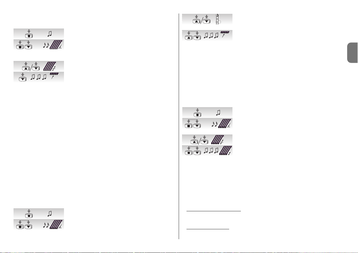
Italiano – 7
IT
––––––––––––––––––––––––––––––––––––––––––––––––––––––––––––––––––––––––––––
Tabella “A11” - Programmazione posizione “2”
––––––––––––––––––––––––––––––––––––––––––––––––––––––––––––––––––––––––––––
01. Tenere premuto il tasto ■ di un trasmettitore già memo-
rizzato fino a sentire un bip (dopo circa 5 secondi).
02. Premere e tenere premuto i tasti ■▼per altri 5 secondi
fino a sentire 2 bip veloci. A questo punto la tenda si porta automaticamente nella posizione del fine corsa basso
posizione “1”).
03. Entro 5 secondi utilizzare i tasti ▼ e ▲ per posizionare la
tenda nella posizione di ritiro desiderata.
04. Confermare entro 5 secondi la posizione premendo il
tasto ■ del trasmettitore fino a sentire 3 bip. Successivamente la tenda si porta nella posizione di fine corsa basso (posizione “1”) programmato.
Nota: se non si conferma la programmazione come descritto al punto 4 le modifiche vengono abortite e vengono mantenute le programmazioni precedenti.
Se dopo aver programmato questa funzione si desidera eliminarla occorre eseguire la procedura indicata in tabella A13, saltando il passo N°3 cioè senza modificare la posizione "1".
Quando viene programmata la posizione “2”, la centrale elettronica calcola automaticamente la differenza tra la posizione “2” e la posizione “1”, in modo che, ad ogni comando
di discesa, la tenda scenda fino alla maggiore delle due posizioni e poi recupera il telo fino
alla minore delle 2 posizioni.
4.3.8 - Programmazione della funzione “FTC”
Dopo aver programmato le posizioni "0" e "1"; se si desidera, è possibile programmare la
posizione "S" che attiva la funzione "FTC" per l'automazione di tende munite di un meccanismo di aggancio automatico. Affinché il meccanismo funzioni correttamente occorre che
la posizione "1" sia programmata qualche centimetro dopo il punto di aggancio, in modo
che in salita dal punto "1" avvenga l'aggancio; e che la posizione "S" sia programmata
qualche centimetro dopo il punto di sgancio, in modo che la salita dal punto "S" avvenga
liberamente.
Per programmare la posizione “S” seguire la procedura indicata in tabella “12”:
––––––––––––––––––––––––––––––––––––––––––––––––––––––––––––––––––––––––––––
Tabella “A12” - Programmazione Posizione di Sgancio “S”
––––––––––––––––––––––––––––––––––––––––––––––––––––––––––––––––––––––––––––
01. Tenere premuto il tasto ■ di un trasmettitore già memo-
rizzato fino a sentire un bip (dopo circa 5 secondi).
02. Premere e tenere premuto i tasti ■▼per altri 5 secondi
fino a sentire 2 bip veloci.
A questo punto la tenda si porta automaticamente nella
posizione “1”.
03. Entro 5 secondi utilizzare i tasti ▼ e ▲ per posizionare la
tenda nella posizione di sgancio “S” (inferiore alla posizione “1”).
04. Confermare entro 5 secondi la posizione premendo contemporaneamente i tasti ▼ e ▲ del trasmettitore fino a
sentire 3 bip. A questo punto la tenda si porta automaticamente nella posizione “0”.
Nota: se non si conferma la programmazione come descritto al punto 4 le modifiche vengono abortite e vengono mantenute le programmazioni precedenti.
Se dopo aver programmato questa funzione si desidera eliminarla occorre eseguire la procedura indicata in tabella A13, saltando il passo N°3 cioè senza modificare la posizione “1”.
4.3.9 - Modifica posizione “1”
Per spostare la posizione “1” Seguire la procedura indicata in tabella “A13”:
––––––––––––––––––––––––––––––––––––––––––––––––––––––––––––––––––––––––––––
Tabella “A13” - Modifica della posizione “1”
––––––––––––––––––––––––––––––––––––––––––––––––––––––––––––––––––––––––––––
01. Tenere premuto il tasto ■ di un trasmettitore già memo-
rizzato fino a sentire un bip (dopo circa 5 secondi).
02. Premere e tenere premuto i tasti ■▼per altri 5 secondi
fino a sentire 2 bip veloci. A questo punto la tenda si porta automaticamente nella posizione “1”.
03. Entro 5 secondi utilizzare i tasti ▼ e ▲ per riposizionare
la tenda nella nuova posizione da programmare.
04. Confermare entro 5 secondi la posizione premendo contemporaneamente i tasti ■▼del trasmettitore fino a
sentire 3 bip e un breve movimento salita discesa.
Nota: se non si conferma la programmazione come descritto al punto 4 le modifiche vengono abortite e vengono mantenute le programmazioni precedenti.
Modificando la posizione "1" si eliminano anche le funzioni "FRT" e "FTC".
4.4 - Cancellazione della memoria
Se dovesse rendersi necessario cancellare i trasmettitori e le programmazioni, si può eseguire la sequenza indicata in tabella A14.
La cancellazione è possibile
:
• con un trasmettitore non memorizzato iniziando la procedura dal punto A.
• con un trasmettitore già memorizzato iniziando la procedura dal punto 1.
Si possono cancellare
:
• solo i trasmettitori memorizzati, terminando al punto 4.
5s...
5s...
5s...
5s...
5s...
1
S
5s...
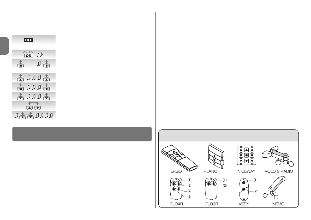
8 – Italiano
IT
• tutto (trasmettitori, livello sensori, indirizzo TTBUS…), completando la procedura fino al
punto 6.
––––––––––––––––––––––––––––––––––––––––––––––––––––––––––––––––––––––––––––
Tabella “A14” - Cancellazione della memoria
––––––––––––––––––––––––––––––––––––––––––––––––––––––––––––––––––––––––––––
A. A motore non alimentato attivare l'ingresso passo-passo
(collegare il filo Bianco col Bianco/Nero) e mantenerlo
attivo fino alla fine della procedura.
B. Collegare il motore all'alimentazione da rete ed attende-
re i bip iniziali.
01. Premere e tenere premuto il tasto ■ di un trasmettitore
(circa 5 secondi) fino a sentire un bip; poi rilasciare il
tasto ■ .
02. Tenere premuto il tasto ▲ del trasmettitore fino a sentire 3
bip. Rilasciare il tasto ▲ esattamente durante il terzo bip.
03. Tenere premuto il tasto ■ del trasmettitore fino a sentire 3
bip. Rilasciare il tasto ■ esattamente durante il terzo bip.
04. Tenere premuto il tasto ▼ del trasmettitore fino a sentire 3
bip. Rilasciare il tasto ▼ esattamente durante il terzo bip.
05. Per cancellare tutto: entro 2 secondi, premere entrambi i
tasti ▲ e ▼.
06. Rilasciare i tasti ▲ e ▼ al primo dei 5 bip che confermano la cancellazione.
I motori serie NEOMAT-T, riconoscono i trasmettitori della serie ERGO, PLANO, NICEWAY,
VOLO S RADIO e NEMO, (vedi capitolo 5.1 “Trasmettitori utilizzabili”).
Inoltre con opportune procedure di memorizzazione dei trasmettitori è possibile associare
a ciascun tasto del trasmettitore un particolare comando (vedi capitolo 5.2 “Programmazione trasmettitori in Modo I e Modo II”).
Attenzione: per le programmazioni utilizzare solamente trasmettitori memorizzati in
Modo I.
5.1 - Trasmettitori utilizzabili
Nella tabella A15 sono indicati i trasmettitori che possono essere utilizzati con il relativo tipo
di codifica.
5
Approfondimenti
––––––––––––––––––––––––––––––––––––––––––––––––––––––––––––––––––––––––––––
Tabella “A15” - Trasmettitori
• ERGO1 - ERGO4 - ERGO6 • PLANO1 - PLANO4 - PLANO6 - PLANO TIME • VOLO S
RADIO • NEMO • NICEWAY (tutta la linea) • FLO1R - FLO2R - FLO4R • VERY VR •
––––––––––––––––––––––––––––––––––––––––––––––––––––––––––––––––––––––––––––
5.2 - Memorizzazione dei trasmettitori in Modo I e Modo II
Nelle tabelle “A1” e “A2” è stata descritta la memorizzazione dei trasmettitori in “Modo I”
dove ad ogni tasto è assegnato un preciso comando: tasto ▲ (1) = “Salita”; tasto ■ (2) =
“Stop”; tasto ▼ (3) = “Discesa”.
È possibile memorizzare i trasmettitori anche in “Modo II” questa modalità permette maggiore flessibilità dell'utilizzo dei tasti dei trasmettitori. Sullo stesso motore NEOMAT-T si
possono memorizzare sia trasmettitori in Modo I che in Modo II.
5.2.1 - Modo I
In Modo I, il comando associato ai tasti del trasmettitore è fisso: tasto ▲ (1) comanda la
“Salita”; il tasto ■ (2) comando lo “Stop”; il tasto ▼ (3) comanda la “Discesa”, un eventuale tasto 4 comanda lo “Stop”.
In Modo I si esegue una unica fase di memorizzazione per ogni trasmettitore e viene occupato un solo posto in memoria. Durante la memorizzazione in Modo I non ha importanza
quale tasto viene premuto. Per memorizzare o cancellare i trasmettitori in Modo I vedere
tabelle A1 ed A2.
P. P.
5s...
Tabella “A15”
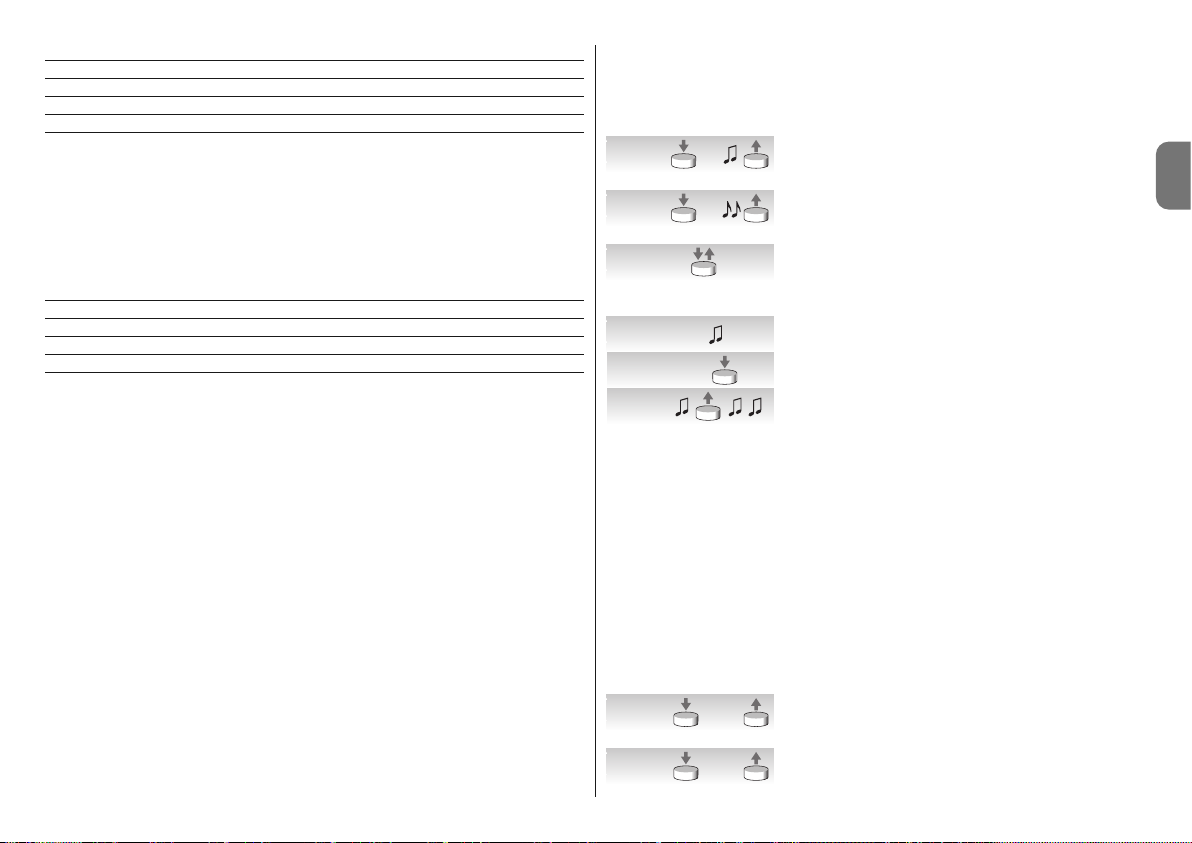
Italiano – 9
IT
Tasto Comando
Tasto ▲ oppure 1 Salita
Tasto ■ oppure 2 Stop
Tasto ▼ oppure 3 Discesa
Tasto 4 Stop
5.2.2 - Modo II
In Modo II è possibile associare ad ogni tasto del trasmettitore uno dei 4 possibili comandi: 1 = Passo-Passo; 2 = Salita-Stop; 3 = Discesa-Stop, 4 = Stop.
In Modo II si esegue una fase di memorizzazione per ogni tasto ed ognuno occupa un
posto in memoria. Durante la memorizzazione in Modo II viene memorizzato il tasto premuto. Se si desidera assegnare ad un altro tasto dello stesso trasmettitore un altro comando
è necessaria una nuova memorizzazione.
N° Comando
1 Passo-Passo” (salita-stop-discesa-stop…),
2 Salita-Stop (salita-stop-salita-stop…)
3 Discesa-Stop (discesa-stop-discesa-stop…)
4 Stop
5.2.3 - Esempio di memorizzazione mista Modo I e Modo II
Sfruttando opportunamente le memorizzazioni in Modo I e Modo II è possibile creare dei
comandi di gruppo come nell'esempio riportato in fig. F.
• Il trasmettitore T1 (Ergo1) memorizzato in Modo I su A1 e A2 comanda la salita, lo stop
o la discesa simultaneamente sia A1 che A2.
• Il trasmettitore T2 (Plano1) memorizzato in Modo I solo su A3 comanda la salita, lo stop
o la discesa solo di A3.
• Il trasmettitore T3 (Planotime) memorizzato in Modo I solo su A4 comanda la salita, lo
stop o la discesa solo di A4.
• Il trasmettitore T4 (WM001C) memorizzato in Modo II (Passo-Passo) comanda solo A4.
• Il trasmettitore T5 (WM003G) memorizzato in Modo I per comandare col gruppo 1 su A1
e A2; col gruppo 2 su A3 e col gruppo 3 su A4; comanda la salita, lo stop o la discesa
di A1 ed A2, A3 oppure A4.
• Il trasmettitore T6 (Flo4R) memorizzato in Modo II su A4 (tasti 1 e 3) su A5 (tasto 2) e su
A6 (tasto 4) comanda la salita e la discesa di A4, oppure l'apertura del portone da garage A5 oppure l'apertura del cancello automatico A6.
ATTENZIONE:
• Con un trasmettitore memorizzato in Modo II non è possibile effettuare la programmazione di alcune funzioni (posizioni, livelli…) visto che in questa sequenza è richiesta la
pressione di tasti diversi, ad esempio il tasto ■ ed il tasto ▲.
• Con un trasmettitore memorizzato in Modo II non possono essere utilizzati i comandi di
“gruppo multiplo”.
Quando uno o più trasmettitori sono già memorizzati, è possibile memorizzarne altri in
Modo II come indicato in tabella A16.
––––––––––––––––––––––––––––––––––––––––––––––––––––––––––––––––––––––––––––
Tabella “A16” - Memorizzazione di altri trasmettitori in Modo II
––––––––––––––––––––––––––––––––––––––––––––––––––––––––––––––––––––––––––––
01. Premere e tener premuto il tasto da memorizzare del
nuovo trasmettitore (circa 5 secondi) fino a sentire un
bip; poi rilasciare il tasto.
02. Entro 5 secondi premere e tenere premuto il tasto di un
trasmettitore vecchio e già memorizzato (circa 5 secondi) fino a sentire 2 bip, poi rilasciare il tasto.
03. Entro 5 secondi iniziare a premere lo stesso tasto del trasmettitore vecchio un numero di volte pari al comando
desiderato: 1 = “passo-passo” 2 = “salita” 3 = “discesa”
4 = “stop”.
04. Dopo circa 3 secondi si sentirà un numero di bip pari al
comando selezionato.
05. Entro 2 secondi premere lo stesso tasto del nuovo trasmettitore.
06. Rilasciare il tasto al primo dei 3 bip che confermano la
memorizzazione.
Se al punto 5 non si sente il numero di bip uguale al comando desiderato, basta non premere alcun tasto ed aspettare alcuni secondi per terminare la programmazione senza nessuna memorizzazione.
Nota: se la memoria è piena (14 trasmettitori) si sentiranno 6 Bip ed il trasmettitore non
potrà essere memorizzato.
È possibile memorizzare in modo semplice un nuovo trasmettitore mantenendo le caratteristiche del vecchio trasmettitore seguendo la procedura di tabella A17. Il nuovo trasmettitore così memorizzato erediterà le caratteristiche di quello vecchio, cioè se il vecchio era
memorizzato in Modo I, anche il nuovo funzionerà in Modo I, se il vecchio era memorizzato in Modo II anche il tasto del nuovo trasmettitore verrà associato allo stesso comando di
quello vecchio.
––––––––––––––––––––––––––––––––––––––––––––––––––––––––––––––––––––––––––––
Tabella “A17” - Memorizzazione di altri trasmettitori
––––––––––––––––––––––––––––––––––––––––––––––––––––––––––––––––––––––––––––
01. Premere e tener premuto il tasto da memorizzare del
nuovo trasmettitore per almeno 3 secondi, poi rilasciare
il tasto.
02. Premere e tener premuto il tasto già memorizzato del
vecchio trasmettitore per almeno 3 secondi, poi rilasciare il tasto.
5s.
nuovo
5s.
vecchio
1- 4
nuovo
1- 43s.
nuovo
>3s.
nuovo
>3s.
vecchio

10 – Italiano
IT
03. Premere e tener premuto il tasto da memorizzare del
nuovo trasmettitore per almeno 3 secondi, poi rilasciare
il tasto.
04. Premere e tener premuto il tasto già memorizzato del
vecchio trasmettitore per almeno 3 secondi, poi rilasciare il tasto.
05. Si sentiranno 3 bip che confermano la memorizzazione
del nuovo trasmettitore.
Nota: se la memoria è piena (14 trasmettitori) si sentiranno 6 Bip ed il trasmettitore non
potrà essere memorizzato.
Questo prodotto è parte integrante dell'automazione, e dunque, deve essere smaltito insieme con essa.
Come per le operazioni d'installazione, anche al termine della vita di questo prodotto, le
operazioni di smantellamento devono essere eseguite da personale qualificato.
Questo prodotto è costituito da vari tipi di materiali: alcuni possono essere riciclati, altri
devono essere smaltiti. Informatevi sui sistemi di riciclaggio o smaltimento previsti dai regolamenti vigenti sul vostro territorio, per questa categoria di prodotto.
Attenzione! – alcune parti del prodotto possono contenere sostanze inquinanti o pericolose che, se disperse nell’ambiente, potrebbero provocare effetti dannosi sull'ambiente stesso e sulla salute umana.
Come indicato dal simbolo a lato, è vietato gettare questo prodotto nei rifiuti
domestici. Eseguire quindi la “raccolta separata” per lo smaltimento, secondo
i metodi previsti dai regolamenti vigenti sul vostro territorio, oppure riconsegnare il prodotto al venditore nel momento dell'acquisto di un nuovo prodotto
equivalente.
Attenzione! – i regolamenti vigenti a livello locale possono prevedere pesanti sanzioni in
caso di smaltimento abusivo di questo prodotto.
❏ Dopo l'alimentazione il motore non emette nessun Bip e l'ingresso PassoPasso non comanda nessun movimento.
Controllare che il motore sia alimentato alla tensione di rete prevista, se l'alimentazione è
corretta è probabile vi sia un guasto grave ed il motore deve essere riparato dal centro
assistenza.
❏ Dopo un comando il motore non si muove.
• Se fino a poco prima funzionava potrebbe essere intervenuta la protezione termica,
basta aspettare qualche minuto che il motore si raffreddi.
• Verificare se funziona l'ingresso “passo-passo” unendo per un istante i conduttori Bianco e Nero/Bianco.
• Verificare che vi sia almeno un trasmettitore memorizzato controllando che all'accensione il motore emetta dei Bip brevi.
• Verificare che vi sia “comunicazione” tra trasmettitore e motore tenendo premuto il tasto
■ (2) di un trasmettitore (memorizzato o non) per almeno 5 secondi, se si sente un Bip
significa che il motore riceve il segnale dal trasmettitore quindi passare all'ultima verifica;
altrimenti eseguire la prossima verifica.
• Verificare la corretta emissione del segnale radio del trasmettitore con questa prova
7
Cosa fare se... cioè piccola guida se qualcosa non va!
6
Smaltimento del prodotto
>3s.
nuovo
>3s.
vecchio

Italiano – 11
IT
Caratteristiche tecniche motori tubolari NEOMAT-MT e NEOMAT-LT
• Tensione di alimentazione e frequenza: Vedere dati tecnici sull'etichetta di ogni
modello
• Corrente e potenza: Vedere dati tecnici sull'etichetta di ogni modello
• Coppia e velocità: Vedere dati tecnici sull'etichetta di ogni modello
• Diametro del motore: NEOMAT-MT = 45mm; NEOMAT-LT = 58mm
• Precisione (risoluzione) del finecorsa elettronico: maggiore di 0,55° (dipende dalla
versione di NEOMAT-T)
• Precisione delle posizioni degli arresti di finecorsa: Classe 2 (± 5%)
• Resistenza meccanica: secondo EN 14202
• Tempo di funzionamento continuo: Massimo 4 minuti
• Grado di protezione: IP 44
• Temperatura di funzionamento: -20 ÷ +55 °C
• Lunghezza cavo di connessione: 3 m
• Tensione segnali (passo-passo, TTBUS…): Circa 24 V
• Livelli sensore vento (anemometro): 5 pari a circa 5, 10, 15, 30 o 45 Km/h (con ane-
mometri VOLO o VOLOS)
• Livelli sensore sole: 5 pari a circa 5, 10, 15, 30 o 45 Klux (con VOLOS )
• Lunghezza cavi segnali (passo-passo, TTBUS…): massimo 30m se in vicinanza ad
altri cavi, altrimenti 100m
• Frequenza ricevitore radio: 433.92 MHz
• Codifica ricevitore radio: 52 Bit rolling code FLOR e FLOR+INFO
• N° trasmettitori memorizzabili: 14, compresi massimo 3 sensori climatici VOLO-S-
Radio
• Portata dei trasmettitori: stimata in 150 m in spazio libero e 20m se all'interno di
edifici (*)
Note:
– (*) La portata dei trasmettitori può essere influenzata da altri dispositivi che operano nelle
vicinanze alla stessa frequenza del trasmettitore (ad esempio radiocuffie, sistemi di
allarme, ecc.), provocando interferenze con il ricevitore. Nei casi di forti interferenze, Nice
non può offrire nessuna garanzia circa la reale portata dei propri dispositivi radio.
– Tutte le caratteristiche tecniche riportate, sono riferite ad una temperatura ambientale di
20°C (± 5°C).
– Nice S.p.a. si riserva il diritto di apportare modifiche al prodotto, in qualsiasi momento lo
riterrà necessario, mantenendone la stessa destinazione d’uso e le funzionalità.
empirica: premere un tasto ed appoggiare il led all'antenna di un comune apparecchio
radio (meglio se di tipo economico) acceso e sintonizzato sulla banda FM alla frequenza
di 108,5Mhz o quanto più prossima; si dovrebbe ascoltare un leggero rumore con pulsazione gracchiante.
• Verificare, premendo lentamente, uno per volta tutti i tasti del trasmettitore, se nessuno
comanda un movimento del motore significa che quel trasmettitore non è memorizzato.
❏ Dopo un comando via radio si sentono 6 Bip e la manovra non parte.
Il radiocomando e fuori sincronismo, bisogna ripetere la memorizzazione del trasmettitore.
❏ Dopo un comando si sentono 10 Bip poi parte la manovra.
L'autodiagnosi dei parametri in memoria ha rilevato qualche anomalia (posizioni, indirizzo
TTBUS, livello vento, sono errati), cancellare la memoria e provare a ripetere le programmazioni.
❏ In salita, prima di raggiungere la posizione prevista (pos. “0”, pos. “I”), il
motore si ferma e poi si sente che per 3 tentativi cerca di ripartire.
Può essere normale: in salita quando viene rilevato uno sforzo eccessivo, il motore viene
spento per circa 1 secondo e poi si ritenta di portare a termine la manovra; verificare se ci
sono ostacoli che impediscono il movimento.
❏ In discesa prima di raggiungere la posizione prevista (pos. “1”, pos “I”), il
motore si ferma.
Può essere normale: in discesa, quando viene rilevato uno sforzo eccessivo, il motore viene spento; verificare se ci sono ostacoli che impediscono il movimento.
❏ Il motore si muove solo a “uomo presente”.
Se le posizioni “0” e “1” non sono state programmate il movimento del motore in salita e in
discesa avviene solo a uomo presente. Programmare le posizioni “0” e “1”.
❏ Il motore si muove correttamente in salita, ma a “uomo presente” in discesa.
L'autodiagnosi dei parametri in memoria ha rilevato una anomalia nella posizione del motore. Comandare la tenda fino a completare tutta la manovra di salita.

12 – Italiano
IT
DICHIARAZIONE CE DI CONFORMITÀ
Nota - Il contenuto di questa dichiarazione corrisponde a quanto dichiarato nell’ultima revisione disponibile, prima
della stampa di questo manuale, del documento ufficiale depositato presso la sede di Nice Spa. Il presente testo è
stato riadattato per motivi editoriali.
Numero: 223/Neomat T Revisione: 3
Il sottoscritto Luigi Paro, in qualità di Amministratore Delegato, dichiara sotto la propria responsabilità che il prodotto:
Nome produttore: NICE s.p.a.
Indirizzo: Via Pezza Alta, 13, Z.I. Rustignè, 31046 - Oderzo (TV) Italia
Tipo: Motoriduttore tubolare per tende in cassonetto con centrale incorporata e ricevitore radio
Modelli: Neomat MT, Neomat LT
Accessori: radiocomandi serie Ergo, Plano, NiceWay, VOLO-S-Radio; anemometri VOLO, VOLO-S
risulta conforme a quanto previsto dalla seguente direttiva comunitaria:
• 1999/5/CE DIRETTIVA 1999/5/CE DEL PARLAMENTO EUROPEO E DEL CONSIGLIO del 9 marzo 1999 riguar-
dante le apparecchiature radio e le apparecchiature terminali di telecomunicazione e il reciproco riconoscimento
della loro conformità, secondo le seguenti norme armonizzate:
- Protezione della salute: EN 50371:2002
- Compatibilità elettromagnetica: EN 301 489-1 V1.8.1:2008; EN 301 489-3 V1.4.1:2002
- Sicurezza elettrica: EN 60950-1:2006
- Spettro radio: EN 300 220-2 V2.1.2:2007
Inoltre, risulta conforme a quanto previsto dalle seguenti direttive comunitarie, così come modificate dalla Direttiva
93/68/CEE del consiglio del 22 Luglio 1993:
• 2006/95/CE DIRETTIVA 2006/95/CE DEL PARLAMENTO EUROPEO E DEL CONSIGLIO del 12 dicembre 2006
concernente il ravvicinamento delle legislazioni degli Stati membri relative al materiale elettrico destinato ad essere
adoperato entro taluni limiti di tensione, secondo le seguenti norme armonizzate: EN 60335-1:2002 + A1:2004 +
A11:2004 + A12:2006 + A2:2006 + A13:2008; EN 60335-2-97:2006 + A11:2008; EN50366:2003 + A1:2006
• 2004/108/CE DIRETTIVA 2004/108/CE DEL PARLAMENTO EUROPEO E DEL CONSIGLIO del 15 dicembre 2004
concernente il ravvicinamento delle legislazioni degli Stati membri relative alla compatibilità elettromagnetica e che
abroga la direttiva 89/336/CEE, secondo le seguenti norme: EN 55014-1:2006; EN 55014-2:1997 + A1:2001; EN
61000-3-2:2006; EN 61000-3-3:2007
Oderzo, 28 luglio 2009
Luigi Paro
(Amministratore Delegato)

Français – 1
FR
FRANÇAIS
instructions originales
ATTENTION ! - Cette notice technique contient d'im-
portantes consignes de sécurité concernant l'INSTALLATION et l'UTILISATION du produit; conserver
ces instructions.
ATTENTION ! - L'installation incorrecte peut entraîner
de graves blessures. Pour cette raison, durant les
pha ses du travail, nous recommandons de suivre
attentivement toutes les instructions d'installation
contenues dans la notice technique.
ATTENTION ! - Pour la sécurité des personnes, il est
important de respecter ces instructions.
• Les moteurs de la série NEOMAT-T, dans les versions
NEOMAT-MT Ø 45 mm et NEOMAT-LT Ø 58 mm sont
destinés à l’automatisation du mouvement de stores
munis de caisson ; toute autre utilisation est impropre
et interdite !
• Les moteurs sont projetés pour usage résidentiel ; le temps
de travail continu maximum prévu est de 4 mi nutes.
• Dans le choix du type de moteur en fonction de l'application, on devra considérer le couple nominal et le temps
de fonctionnement indiqués sur la plaque.
• Le diamètre minimum du tube d'enroulement dans
lequel le moteur peut être installé est de 52 mm pour
NEOMAT-MT, avec des couples jusqu'à 35 Nm, 60 mm
pour NEOMAT-MT avec des couples supérieurs à 35 Nm
et 70 mm pour NEOMAT-LT.
• L'installation doit être effectuée par du personnel technique dans le plein respect des normes de sécurité.
• Avant l'installation, il faut éloigner tous les câbles électriques qui ne sont pas nécessaires ; tous les mécanismes non nécessaires pour le fonctionnement motorisé doivent être désactivés.
• Les parties en mouvement du moteur doivent être proté-
Avertissements et précautions
pour la sécurité
gées si ce dernier est monté à une hauteur inférieure à
2,5 m.
• Pour les stores, la distance à l'horizontale entre le store
complètement ouvert et n'importe quel objet permanent
doit être garantie d'au moins 0,4 m.
• Le câble d'alimentation en PVC fourni avec les moteurs
série NEOMAT-T les rend adaptés à l'installation à l'intérieur ; pour l'installation à l'extérieur, il faut protéger tout
le câble avec un conduit isolant ou bien demander le
modèle spécifique avec câble S05RN-F.
• Ne pas soumettre le moteur tubulaire à des écrasements,
chocs, chutes ou contact avec des liquides de quelque
nature que ce soit ; ne pas percer ni appliquer de vis sur
toute la longueur du moteur tubulaire (voir fig. 1).
• L'interrupteur de commande doit être visible de l'application mais éloigné des parties en mouvement et à au
moins 1,5 m de hauteur.
• N'effectuer de modifications sur aucune des parties si
elles ne sont pas prévues dans la présente notice technique. Des opérations de ce type entraîneront obligatoirement des problèmes de fonctionnement. NICE décline
toute responsabilité en cas de dommages dérivant de
produits modifiés.
• S'adresser à du personnel technique compétent pour
toute maintenance et réparation.
• Maintenir les personnes à distance de la fermeture à
enroulement quand elle est en mouvement.
• Ne pas l'actionner quand des travaux sont effectués, par
exemple : durant le lavage des vitres ; en cas de commande automatique, couper également le courant.
• Ne pas laisser les enfants jouer avec les commandes et
maintenir les télécommandes hors de leur portée.
• S'ils sont présents contrôler souvent les ressorts d'équilibrage ou l'usure des câbles.
ATTENTION ! - Les capteurs climatiques des séries Volo et
Nemo ne doivent pas être considérés comme des dispositifs de sécurité qui éliminent les dommages causés
au store par la pluie ou un vent fort (de fait, une banale
coupure de courant rendrait impossible le mouvement
automatique du store). Les capteurs climatiques doivent
être considérés comme partie d’un automatisme utile à
la protection du store et à son confort d’utilisation.
Nice décline toute responsabilité pour les dommages
matériels dus à des évènements atmosphériques non
détectés par les capteurs.
ATTENTION ! - En cas de pluie, pour éviter le phénomène
des poches d'eau, il est nécessaire rentrer le store articulé si la pente est inférieure à 25 % ou à la valeur
conseillée par le fabricant.
ATTENTION ! - En cas de formation de glace, le fonction-
nement pourrait endommager la fermeture à enroulement.
ATTENTION ! - Certaines phases de la programmation uti-
lisent les butées mécaniques du store pour bloquer la
course du moteur ; c’est la raison pour laquelle il est in dispensable de choisir le moteur ayant le couple le plus
adapté aux caractéristiques du store, compte tenu de
l’effort effectif, en évitant les moteurs trop puissants.
Les moteurs série NEOMAT dans les versions NEOMATMT Ø 45 mm et NEOMAT-LT Ø 58 mm, sont des moteurs
électriques, avec réduction du nombre de tours, qui se terminent à une extrémité par un arbre spécial sur lequel peuvent être montées les roues d'entraînement (voir fig. 2). Le
moteur s’installe en l’introduisant dans le tube du store ; il
est en mesure de faire monter ou descendre le store.
La logique de commande incorporée dans le moteur dispose également d'un système de fin de course électronique haute précision qui est en mesure de détecter
constamment la position de la fermeture à enroulement.
Grâce à une opération de programmation, les limites du
mouvement sont mémorisées, c'est-à-dire store fermé et
store ouvert (plus éventuelles positions intermédiaires) ;
après chaque commande, le mouvement s'interrompra
automatiquement quand ces positions seront atteintes. Le
fin de course électronique est en mesure de compenser les
éventuels allongements de la toile (fonction “CAT”) en ga rantissant la fermeture parfaite du caisson et en évitant les
ondulations de la toile quand il est ouvert.
Pour éviter de trop tirer sur la toile quand le store est complètement fermé, les moteurs série NEOMAT-T disposent
de la fonction de réduction de couple « RDC » qui réduit
d’environ 50 % le couple du moteur un peu avant la fermeture. Cette fonction peut être désactivée avec un émetteur
(voir 4.3.2.) ou avec les unités de programmation TTP et
OTT-View qui permettent aussi de choisir entre 3 niveaux
1
Description du produit

2 – Français
FR
de réduction : à 50, à 40 ou à 30 % environ du couple.
Les fonctions CAT et RDC ont été étudiées afin de simuler
le comportement attentif et diligent d'une personne qui
actionne manuellement le store.
Les moteurs série NEOMAT-T contiennent également une
logique de commande électronique avec récepteur radio
incorporé qui fonctionne à une fréquence de 433,92 MHz
avec technologie à code tournant (rolling code), pour
garantir des niveaux de sécurité élevés. Pour chaque
moteur, il est possible de mémoriser jusqu'à 14 émetteurs
de la série ERGO, PLANO et NICEWAY (fig. 3), qui permettent la commande à distance du moteur, ou bien jusqu'à 3
capteurs radio de vent et soleil “VOLO S RADIO” ou
“NEMO” qui commandent automatiquement le moteur en
fonction des conditions climatiques.
La programmation des fins de course et de certaines fonctions supplémentaires peut être faite directement à partir
des émetteurs, un “bip” en guidera les différentes phases.
Une entrée est disponible pour commander les moteurs
également avec une touche externe (avec fonction pas à
pas) ou bien par bus “TTBUS”. À la place de la touche pas
à pas, sur TTBUS on peut connecter la photocellule spécifique F210S qui détecte la présence d'éventuels obstacles
pour empêcher la manœuvre de descente ; pour les
détails, voir les instructions de la photocellule F210S.
Sur l'entrée des capteurs climatiques, on peut connecter
des capteurs de vent, de soleil et de pluie (en option) qui
activent automatiquement le moteur quand les conditions
climatiques le requièrent. Sur les moteurs NEOMAT-T, des
fonctions particulières, qui permettent de résoudre des problèmes spécifiques, peuvent être programmées (fig. A) :
– FRT : cette fonction permet de retirer la toile, d'une
mesure programmable, après l'ouverture complète du
store. Elle permet d'éliminer les ondulations inesthétiques
de la toile quand le store est ouvert. Pour plus de détails,
voir le tableau A10.
– FTC : permet de motoriser des stores qui sont maintenus en tension grâce à un mécanisme d'accrochage automatique, par exemple les stores à montants latéraux
courbes. Pour plus de détails, voir le tableau A11.
ATTENTION ! - Une installation incorrecte peut entraîner de graves blessures.
Préparer le moteur avec la séquence d'opérations suivante
(voir fig. 4 - 5 - 6) :
01. Enfiler la couronne du fin de course (E) sur le moteur
(A) jusqu'à ce qu'elle s'encastre dans la bague correspondante du fin de course (F) en faisant coïncider les
deux rainures ; pousser à fond comme l'indique la fig.
5-(1).
02. Insérer la roue d'entraînement (D) sur l'arbre du mo teur.
03. Sur NEOMAT-MT, fixer la roue d'entraînement avec la
rondelle Seeger par pression. Sur NEOMAT-LT, fixer la
roue d'entraînement avec la rondelle et l'écrou M12.
04. Introduire le moteur ainsi assemblé dans le tube d'en-
roulement jusqu'à ce qu'il touche l'extrémité de la cou ronne (E). Fixer la bague d'entraînement (D) au tube
d'enroulement à l'aide d'une vis M4x10 de ma nière à
éviter les éventuels glissements et déplacements axiaux
du moteur (fig. 6).
05. Bloquer enfin la tête du moteur au support (C) prévu à
cet usage, avec l'éventuelle entretoise, à l'aide des clips
ou de la goupille (B).
2.1 - Connexions électriques
ATTENTION ! - Pour les branchements des moteurs, il
faut prévoir un dispositif omnipolaire de déconne xion
du secteur avec distance entre les contacts d'au
moins 3 mm (sectionneur ou bien fiche et prise, etc.).
ATTENTION ! - Respecter scrupuleusement les con -
nexions prévues, en cas de doute, ne pas tenter en
vain mais consulter les notices techniques disponibles également sur le site “www.niceforyou.com”.
Un branchement erroné peut provoquer des pannes
ou des situations de danger.
Le câble pour les connexions électriques des moteurs
NEOMAT-MT et NEOMAT-LT disposent de 6 conducteurs :
3 conducteurs (étiquette jaune) pour l'alimentation du secteur et 3 conducteurs (étiquette violette) pour les signaux
de commande.
2
Installation
Pour effectuer les branchements électriques voir fig. B. les
dispositifs de connexion ne sont pas fournis avec le produit.
2.1.1 - Alimentation de secteur (brun + bleu +
jaune/vert)
L'alimentation électrique à la tension de secteur doit être
connectée sur les conducteurs : Brun (Phase) ; Bleu (Neutre) et Jaune/Vert. ATTENTION ! - Ne connecter sous
aucun prétexte l'alimentation de secteur (230 V ou 120
V) dans les autres conducteurs.
2.1.2 - Entrée “pas à pas” : (blanc + noir/Blanc)
Pour commander l'automatisme en mode manuel, il est
possible de connecter un simple contact d'un bouton entre
les conducteurs Blanc (entrée pas à pas) et noir/Blanc
(commun) ; le mode de fonctionnement suit la séquence :
montée - arrêt - descente - arrêt.
Si la touche est maintenue enfoncée pendant plus de 3
secondes (mais moins de 10), on a toujours l'activation
d'une manœuvre de montée (celle qui correspond à la
touche ▲ des émetteurs). Si la touche reste enfoncée plus
de 10 secondes, on a toujours l'activation d'une manœuvre de descente (correspondant à la touche ▼ ). Cette particularité peut être utile pour “synchroniser” plusieurs
moteurs vers la même manœuvre, indépendamment de
l'état dans lequel ils se trouvent.
2.1.3 - Entrée “TTBUS” (blanc + noir/blanc)
Le “TTBUS” est un Bus développé pour pouvoir contrôler
de manière indépendante des moteurs ou logiques de
commande, jusqu'à 100 dispositifs, en les connectant simplement en parallèle avec seulement 2 conducteurs. D'autres informations sont disponibles dans les instructions des
produits compatibles avec TTBUS.
À l'entrée TTBUS, on peut connecter les programmateurs
TTP, TTI et O-ViewTT qui permettent de simplifier les opérations de programmation et de gestion des installations ;
pour plus d'informations, consulter les notices techniques
correspondantes.
2.1.4 - Entrée “Photocellule F210S”
(blanc + noir/blanc)
Sur l'entrée “Photocellule F120S” il est possible de con necter la photocellule F210S pour détecter la présence
d'éventuels obstacles et empêcher ainsi la manœuvre de
descente. D'autres détails sur les connexions se trouvent
dans le manuel d'instructions de la photocellule F210 S.

Français – 3
FR
Store complètement
fermé (pos. “0”)
Store ouvert (pos. “1”)
Position intermédiaire (“I”)
Position de début de réduction de couple RDC
dans la manœuvre de fermeture (position non programmable).
Position “2” pour
fonction “FRT”
Position d'accrochage “S” pour
les stores qui
sont maintenus
en tension grâce
à un mécanisme
d'accrochage
automatique
“0”
“A”
“2”
“1”
“S”
E
ATTENTION ! - Les entrées pas à pas, TTBUS et F120S
utilisent physiquement les mêmes conducteurs blanc
+ noir/blanc : on ne peut donc utiliser qu'un type d'entrée à la fois.
2.1.5 - Capteurs climatiques
(noir/blanc + orange/blanc)
Il est possible de connecter à l'entrée “capteurs climatiques” (entre le commun et l'entrée “capteurs climatiques”)
connecter un simple capteur de vent (anémomètre) ou un
capteur “vent - soleil - pluie” spécial.
Si l’on utilise les capteurs de vent, il est possible de
connecter à un même capteur jusqu’à 5 moteurs ou lo giques de commande, en utilisant une connexion en parallèle (respecter la polarité des signaux).
Attention ! - Bien que cela soit possible, la connexion d’un
unique capteur à plusieurs moteurs n’est pas conseillée.
En effet, même si les seuils des différents moteurs sont
réglés sur la même valeur, chaque moteur effectue sa propre mesure et les mouvements automatiques des stores
ne sont pas simultanés.
Pour actionner plusieurs moteurs simultanément, il faut utiliser des capteurs avec leur propre réglage de seuil,
comme par exemple les modèles Volo ST, Volo S Radio et
Nemo.
2.2 - Direction de la sortie du câble (fig. C)
(Uniquement pour le modèle NEOMAT-LT) – Si l'on sou-
haite modifier la direction de sortie du câble, il suffit de :
01. Retirer la protection en la tirant vers l'extérieur. 02.
Plier le câble dans la direction souhaitée. 03. Insérer la protection en la pressant avec force dans son logement.
2.3 - Connecteur et câble d'alimentation
(Uniquement pour le modèle NEOMAT-MT) – Les informations de ce chapitre s’adressent exclusivement au personnel technique du service après-vente.
ATTENTION ! - Si le câble d'alimentation est abîmé, il
faut le remplacer par un câble identique disponible
chez le constructeur ou au centre de service aprèsvente !
S’il est nécessaire de déconnecter le moteur du câble d’alimentation, procéder de la façon suivante (fig. D) : a) - Tourner la bague jusqu'à ce que l'encoche coïncide avec l'une
des dents d'accrochage, puis décrocher. b) - Répéter
l'opération pour l'autre dent. c) - Plier le câble vers l'intérieur et enlever la protection en la tournant délicatement
vers l'extérieur. d) - Débrancher le connecteur en le tirant.
Les moteurs tubulaires série NEOMAT sont équipés d'un
système de fin de course électronique ; la logique de commande électronique interrompt le mouvement quand le
store atteint les positions de fermeture et d'ouverture programmées. Ces positions doivent être mémorisées grâce à
une programmation adéquate qui doit s'effectuer directement avec le moteur installé et le store complètement
monté.
(fig. E) Même si les positions “0” (store fermé) et “1” (store
ouvert) n'ont pas encore été mémorisées, il est quand
même possible de commander le moteur mais le mouvement s'effectuera en mode “commande par action maintenue”.
Il est possible de programmer également les positions sui-
vantes :
• La position intermédiaire « I » pour l’ouverture partielle du
store. Cette position peut être programmée également
dans un second temps.
• La position “2” nécessaire pour activer la fonction “FRT”
qui permet de tendre la toile quand le store est complètement ouvert ;
• La fonction “FTC” pour l'automatisation de stores munis
d'un mécanisme d'accrochage automatique.
3
Réglages

4 – Français
FR
La phase de programmation se compose de trois étapes :
1. Mémorisation des émetteurs
2. Programmation des positions “0” et “1”
3. Programmations optionnelles
Pour qu'un émetteur puisse commander un moteur série NEOMAT-T, il faut procéder à la
mémorisation suivant les indications du tableau A1.
ATTENTION :
• Toutes les séquences de mémorisation sont temporisées, c'est-à-dire qu'elles
doivent être effectuées dans les limites de temps prévues.
• Avec des émetteurs qui prévoient plusieurs “groupes”, avant de procéder à la mémori-
sation, il faut choisir le groupe de l'émetteur auquel associer le moteur.
• La mémorisation par radio peut s'effectuer dans tous les récepteurs qui se trouvent
dans le rayon de portée de l'émetteur ; il faut donc alimenter uniquement celui qui est
concerné par l'opération.
Il est possible de vérifier s'il existe déjà des émetteurs mémorisés dans le moteur ; pour
cela, il suffit de vérifier le nombre de bips émis au moment de l'allumage du moteur :
- 2 longs bips = Aucun émetteur mémorisé.
- 2 bips brefs = Il y a déjà des émetteurs mémorisés.
4.1 - Programmation des émetteurs
––––––––––––––––––––––––––––––––––––––––––––––––––––––––––––––––––––––––––––
Tableau “A1” - Mémorisation du premier émetteur (en mode I)
––––––––––––––––––––––––––––––––––––––––––––––––––––––––––––––––––––––––––––
01. Connecter le moteur à l'alimentation de secteur, on
entendra immédiatement 2 longs bips.
02. Dans les 5 secondes qui suivent, presser et maintenir
enfoncée la touche ■ de l'émetteur à mémoriser (pendant 3 secondes environ).
03. Relâcher la touche ■ quand on entend le premier des 3
bips qui confirment la mémorisation.
Pour mémoriser d'autres émetteurs, voir tableau A2.
Quand un ou plusieurs émetteurs ont déjà été mémorisés, il est possible d'en activer d'autres en suivant les indications du tableau A2.
4
Programmations
––––––––––––––––––––––––––––––––––––––––––––––––––––––––––––––––––––––––––––
Tableau “A2” - Mémorisation d'autres émetteurs (en mode I)
––––––––––––––––––––––––––––––––––––––––––––––––––––––––––––––––––––––––––––
01. Presser et maintenir enfoncée la touche ■ du nouvel
émetteur (pendant environ 5 secondes) jusqu'à ce que
l'on entende un bip, puis relâcher la touche ■.
02. Presser lentement 3 fois la touche ■ d'un émetteur existant déjà mémorisé.
03. Presser encore la touche ■ du nouvel émetteur. Relâ-
cher la touche ■ quand on entend le premier des 3 bips
qui confirment la mémorisation.
Note : Si la mémoire est pleine (14 émetteurs), 6 bips indiqueront que l'émetteur ne peut
pas être mémorisé.
4.2 - Programmation des positions “0” et “1”
Pour programmer les positions, il faut utiliser un émetteur déjà mémorisé en mode I. Tant
que les positions 0 et 1 ne sont pas mémorisées dans la logique de commande, les mouvements s'effectuent en mode “commande par action maintenue”. Initialement, la direction
du moteur n'est pas définie mais à la fin du point 1 du tableau A3, la direction du moteur
est automatiquement assignée aux touches des émetteurs.
Pour la programmation des positions “0” et “1”, suivre la procédure indiquée dans le
tableau A3.
––––––––––––––––––––––––––––––––––––––––––––––––––––––––––––––––––––––––––––
Tableau “A3” - Programmation des positions “0” et “1”
––––––––––––––––––––––––––––––––––––––––––––––––––––––––––––––––––––––––––––
01. Presser et maintenir enfoncée la touche ▲ ou la touche ▼
d'un émetteur mémorisé jusqu'à ce que s'achève la fermeture du store et que le moteur s'arrête automatiquement.
02. Presser et maintenir enfoncée la touche ▼ qui fait des-
cendre le store.
03. Relâcher la commande ▼ quand le store atteint la position voulue (“1”). Si nécessaire, ajuster la position avec
les touches ▼ et ▲.
04. Maintenir enfoncée la touche ■ de l'émetteur jusqu'à ce
que l'on entende un bip (au bout de 5 secondes environ).
05. Relâcher puis rappuyer pendant encore 5 secondes la
touche ■ jusqu'à ce que l'on entende un bip 4 bips
rapides.
06. Appuyer sur la touche ▼ jusqu'à ce que 3 bips et un bref
mouvement de montée et de descente signalent que la
hauteur a été mémorisée.
3s...
5s...
x 3
nouveau
existant
nouveau
5s...
5s...

Français – 5
FR
4.3 - Programmations optionnelles
Les programmations optionnelles ne sont possibles qu'après la programmation des positions “0” et “1”.
4.3.1 - Mémorisation de la position intermédiaire “I”
Quand une position intermédiaire I est mémorisée, il est possible d'actionner le store
jusqu'à la position I en appuyant simultanément sur les 2 touches ▲ et ▼ de l'émetteur.
Pour mémoriser la position intermédiaire, suivre la procédure indiquée dans le tableau A4.
––––––––––––––––––––––––––––––––––––––––––––––––––––––––––––––––––––––––––––
Tableau “A4” - Programmation de la position intermédiaire “I”
––––––––––––––––––––––––––––––––––––––––––––––––––––––––––––––––––––––––––––
01. À l'aide des touches ▲ ■ ▼ d'un émetteur, actionner le
store jusqu'à la position I à mémoriser.
02. Maintenir enfoncée la touche ■ de l'émetteur jusqu'à ce
que l'on entende un bip (au bout de 5 secondes environ).
03. Relâcher puis rappuyer pendant encore 5 secondes la
touche ■ jusqu'à ce que l'on entende un bip 4 bips
rapides.
04. Presser simultanément les touches ▼ et ▲ jusqu'à ce
que 3 bips signalent que la hauteur a été mémorisée.
4.3.2 - Désactivation ou réactivation de la réduction de couple en fermeture
(RDC)
La réduction de couple est une fonction qui réduit le couple de traction d’environ 50 % un
peu avant la fermeture complète du store contre le caisson de manière à éviter la tension
excessive de la toile. Cette fonction s’active automatiquement après la programmation des
positions 0 et 1 (la programmation a toujours lieu à la force maximum) mais peut être désactivée (ou réactivée).
Note - l’activation automatique de la fonction RDC n’a pas lieu si la programmation des
positions est faite avec les programmateurs TTP, TTI et O-ViewTT ; dans ces cas-là, si on
le souhaite, la fonction peut être activée manuellement.
––––––––––––––––––––––––––––––––––––––––––––––––––––––––––––––––––––––––––––
Tableau “A5” - Désactivation ou réactivation de la réduction de couple (RDC)
––––––––––––––––––––––––––––––––––––––––––––––––––––––––––––––––––––––––––––
01. Maintenir enfoncée la touche ■ d'un émetteur déjà
mémorisé jusqu'à ce que l'on entende un bip (au bout
de 5 secondes environ).
02. Relâcher puis rappuyer pendant encore 5 secondes la
touche ■ jusqu'à ce que l'on entende un bip 4 bips
rapides.
03. Presser la touche ■ jusqu’au début des bips de signalisation : 3 bips indiquent que la RDC est active (fermeture
à un couple réduit) ; 5 bips indiquent que la RDC est
inactive (fermeture au couple maximum).
4.3.3 - Effacement des positions
Pour modifier les positions mémorisées précédemment mémorisées, il est d'abord nécessaire de les effacer puis de reprogrammer les nouvelles positions.
––––––––––––––––––––––––––––––––––––––––––––––––––––––––––––––––––––––––––––
Tableau “A6” - Effacement de la position intermédiaire “I”
––––––––––––––––––––––––––––––––––––––––––––––––––––––––––––––––––––––––––––
01. Maintenir enfoncée la touche ■ d'un émetteur déjà
mémorisé jusqu'à ce que l'on entende un bip (au bout
de 5 secondes environ).
02. Relâcher puis rappuyer pendant encore 5 secondes la
touche ■ jusqu'à ce que l'on entende un bip 4 bips
rapides.
03. Presser simultanément les touches ▼ et ▲ jusqu'à ce
que 5 bips signalent que la position intermédiaire a été
effacée.
––––––––––––––––––––––––––––––––––––––––––––––––––––––––––––––––––––––––––––
Tableau “A7” - Effacement des positions “0” et “1”
––––––––––––––––––––––––––––––––––––––––––––––––––––––––––––––––––––––––––––
01. Maintenir enfoncée la touche ■ d'un émetteur déjà
mémorisé jusqu'à ce que l'on entende un bip (au bout
de 5 secondes environ).
02. Relâcher puis rappuyer pendant encore 5 secondes la
touche ■ jusqu'à ce que l'on entende un bip 4 bips
rapides.
03. Presser la touche ▼ jusqu'à ce que 5 bips signalent que
les positions 0 et 1 ont été effacées.
ATTENTION : Après avoir effacé les positions « 0 » et « 1 », le store ne pourra être actionné
qu’avec une commande à action maintenue et il sera nécessaire de mémoriser les nouvelles positions.
Note : la position intermédiaire I et la fonction RDC éventuellement programmées ne sont
pas effacées. Si l'on souhaite tout effacer (y compris les codes des émetteurs), se reporter
au tableau “A14”.
4.3.4 - Programmation du seuil du capteur climatique “vent”
Si on connecte à l'entrée “capteurs” un capteur de vent de la série “VOLO” ou “VOLO S”,
5s...
5s...
5s...
5s...
5s...
5s...
(...)
5s...
5s...

6 – Français
FR
la protection “vent” est activée, c'est-à-dire que le store remonte automatiquement si le
vent dépasse le seuil programmé. Si le seuil est dépassé pendant plus de 3 secondes, une
commande correspondant à la touche ▲ s'active et tout autre mouvement est bloqué
jusqu'à ce que le vent redescende en dessous du seuil programmé pendant au moins 1
minute. On peut choisir 5 seuils d'intervention différents : 1 = 5 km/h, 2 = 10 km/h, 3 = 15
km/h, 4 = 30 km/h et 5 = 45 km/h. (le seuil programmé en usine est le n° 3).
Si l’on utilise le capteur « VOLO ST » ou les capteurs radio Volo S Radio et Nemo, les seuils
d’intervention du vent sont directement programmés sur le capteur (voir les instructions
correspondantes).
Pour modifier le seuil programmé :
––––––––––––––––––––––––––––––––––––––––––––––––––––––––––––––––––––––––––––
Tableau “A9” - Changer le seuil d'intervention de la protection “vent”
––––––––––––––––––––––––––––––––––––––––––––––––––––––––––––––––––––––––––––
01. Maintenir enfoncée la touche ■ d'un émetteur mémorisé
(pendant 5 secondes environ) jusqu'à ce que l'on
entende un bip, puis relâcher la touche ■.
02. Presser lentement la touche ▲, un nombre de fois (1, 2,
3, 4 ou 5) égal au seuil voulu.
03. Au bout de quelques instants, on entendra un nombre
de bips égal au seuil voulu.
04. Presser et relâcher la touche ■ pour confirmer.
Si au point 3, on n'entend pas un nombre de bips égal au seuil voulu, il suffit de ne presser
aucune touche et d'attendre quelques secondes pour terminer l'opération sans changer le
seuil.
4.3.5 - Programmation du seuil du capteur climatique “soleil”
Si on connecte à l'entrée “capteurs” un capteur de soleil de la série “VOLO-”, l'automatisme “soleil” s'active, c'est-à-dire que le store descend automatiquement si le soleil
dépasse le seuil programmé. Si le seuil est dépassé pendant plus de 2 minutes, une commande correspondant à la touche ▼ s'active ; ensuite, si le “soleil” descend au-dessous
du seuil programmé pendant 15 minutes, une commande correspondant à la touche ▲
s'active.
On peut choisir 5 seuils d'intervention “soleil” différents : 1 = 5 klx, 2 = 10 klx, 3 = 15 klx, 4
= 30 klx et 5 = 45 klx (le seuil programmé en usine est le n° 3).
––––––––––––––––––––––––––––––––––––––––––––––––––––––––––––––––––––––––––––
Tableau “A10” - Changer le seuil d'intervention de l'automatisme “soleil”
––––––––––––––––––––––––––––––––––––––––––––––––––––––––––––––––––––––––––––
Si on utilise le capteur « VOLO ST » ou les capteurs radio Volo S Radio et Nemo, les seuils
d’intervention du soleil sont directement programmés sur le capteur (voir les instructions
correspondantes).
01. Maintenir enfoncée la touche ■ d'un émetteur mémorisé
(pendant 5 secondes environ) jusqu'à ce que l'on
entende un bip, puis relâcher la touche ■.
02. Presser lentement la touche ▼ un nombre de fois (1, 2,
3, 4 ou 5) égal au seuil voulu
03. Au bout de quelques instants, on entendra un nombre
de bips égal au seuil voulu.
04. Presser et relâcher la touche ■ pour confirmer.
Si au point 3, on n'entend pas un nombre de bips égal au seuil voulu, il suffit de ne presser
aucune touche et d'attendre quelques secondes pour terminer l'opération sans changer le
seuil.
4.3.6 - Changer le sens d’intervention en cas de pluie
Si l’on utilise un capteur de pluie Nemo WSRT, quand le capteur détecte la présence de
pluie, il envoie l’information aux moteurs et un mouvement est commandé dans le sens
programmé (par défaut, le sens programmé est la « montée »).
Pour modifier le sens d’intervention pluie :
01. Maintenir enfoncée la touche ■ d’un émetteur déjà mémorisé jusqu’à ce que l’on
entende un bip (au bout de 5 secondes environ), puis relâcher la touche.
02. Presser lentement la même touche ■ encore 3 fois.
03. Presser la touche indiquant le sens désiré (montée ou descente) ; le moteur émet
alors 3 bips = nouvelle direction mémorisée.
Les mouvements automatiques provoqués par le capteur « soleil » peuvent être désactivés avec une commande de « Soleil OFF » envoyée à l’aide d’un émetteur qui dispose de
cette fonction (Ergo 4, Plano 4, WM004G) et peut être réactivée avec une commande de
« Soleil ON ».
Aux mouvements automatiques provoqués par le capteur « soleil » peuvent être associées
5s...
5s...
x 1 = 5 Km/h
x 2 = 10 Km/h
x 3 = 15 Km/h
x 4 = 30 Km/h
x 5 = 45 Km/h
x 1 = 5 Km/h
x 2 = 10 Km/h
x 3 = 15 Km/h
x 4 = 30 Km/h
x 5 = 45 Km/h
x 1 = 5 Klux
x 2 = 10 Klux
x 3 = 15 Klux
x 4 = 30 Klux
x 5 = 45 Klux
x 1 = 5 Klux
x 2 = 10 Klux
x 3 = 15 Klux
x 4 = 30 Klux
x 5 = 45 Klux
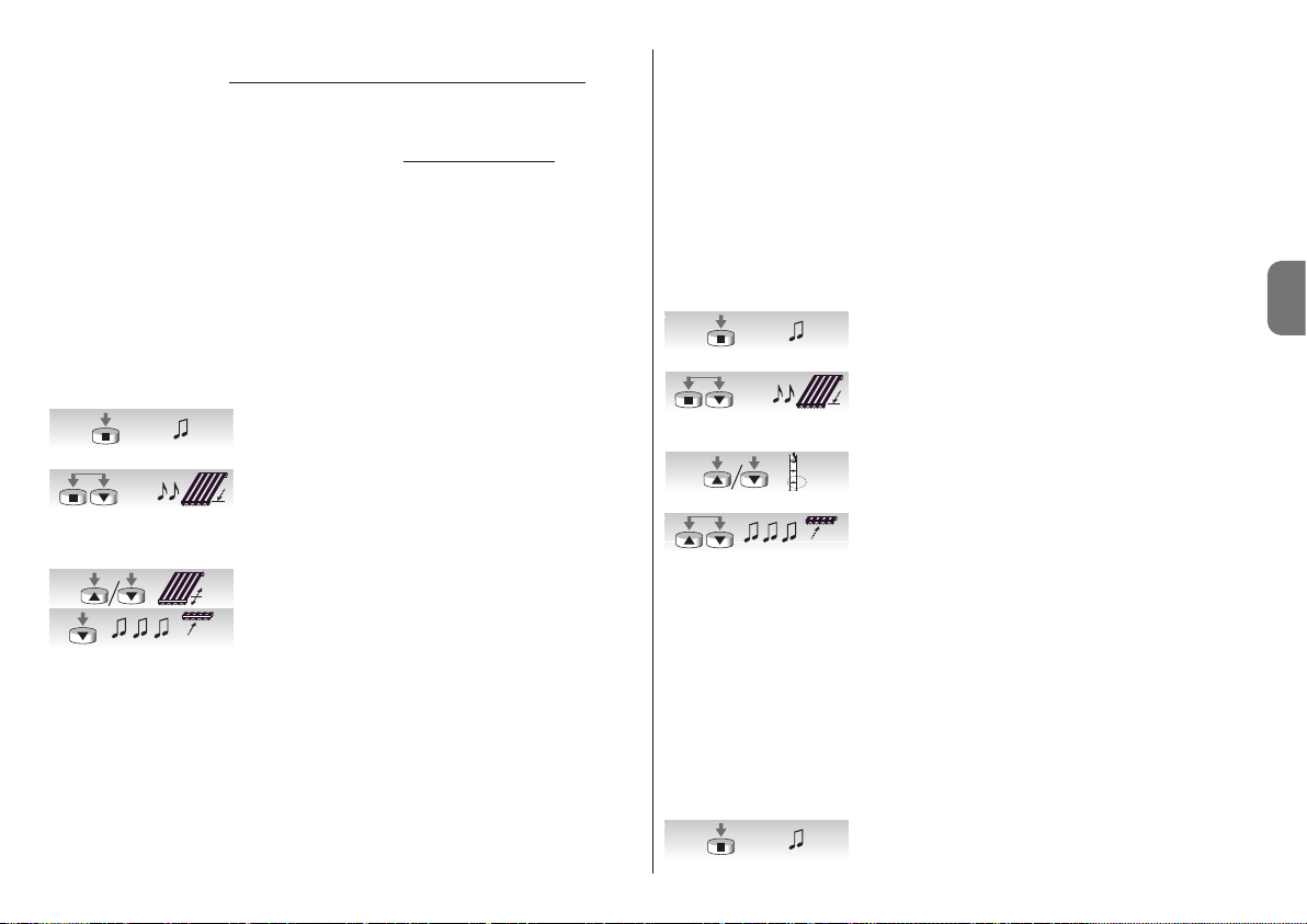
Français – 7
FR
à tout moment également les commandes manuelles envoyées par l’utilisateur avec un
émetteur normal ; celles-ci prévalent sur les commandes du capteur « soleil »
, avec la
modalité décrite dans l’exemple qui suit : si le store est en position « 1 » (atteinte automatiquement par effet du dépassement du seuil « soleil ») et peu après l’utilisateur commande
la remontée du store à la position « 0 », dans les moments successifs, même si le système
continue à détecter le dépassement du seuil « soleil », le store ne bouge pas
(il reste dans
la position commandée par l’utilisateur).
Le « cycle automatique » interrompu par la commande manuelle est rétabli quand le niveau
de l’intensité lumineuse redescend sous le seuil (typiquement au coucher du soleil).
4.3.7 - Programmation de la fonction “FRT”
Après avoir programmé les positions “0” et “1”, si on le souhaite, il est possible de programmer la position 2 qui active la fonction de retrait de la toile FRT.
Pour la programmation de la position 2, suivre la procédure indiquée dans le tableau
“A11”.
––––––––––––––––––––––––––––––––––––––––––––––––––––––––––––––––––––––––––––
Tableau “A11” - Programmation de la position 2
––––––––––––––––––––––––––––––––––––––––––––––––––––––––––––––––––––––––––––
01. Maintenir enfoncée la touche ■ d'un émetteur déjà
mémorisé jusqu'à ce que l'on entende un bip (au bout
de 5 secondes environ).
02. Presser et maintenir enfoncées les touches ■▼pen-
dant encore 5 secondes jusqu'à ce que l'on entende 2
bips rapides. Le store est alors automatiquement ac tionné jusqu'à la position du fin de course bas (position
“1”).
03. Dans les 5 secondes, utiliser les touches ▼ et ▲ pour
positionner le store dans la position de retrait voulue.
04. Confirmer la position dans les 5 secondes en pressant la
touche ■ de l'émetteur jusqu'à ce que l'on entende 3
bips. Le store est alors actionné jusqu'à la position du fin
de course bas (position “1”) programmée.
Note : si la programmation n'est pas confirmée, comme cela est indiqué au point 4, les
modifications sont interrompues et ce sont les programmations précédentes qui sont
maintenues.
Si, après avoir programmé cette fonction, on souhaite l'éliminer, il faut suivre la procédure
indiquée dans le tableau A13 en omettant le point 3, c'est-à-dire sans modifier la position “1”.
Quand la position “2” est programmée, la logique de commande électronique calcule
automatiquement la différence entre la position “2” et la position “1”, de sorte qu'à chaque
commande de descente, le store descende jusqu'à la position la plus haute des deux puis
récupère la toile jusqu'à la position la plus basse.
4.3.8 - Programmation de la fonction “FTC”
Après avoir programmé les positions “0” et “1”, si on le souhaite, il est possible de programmer la position “S”, qui active la fonction “FTC” pour l'automatisation de stores équipés d'un mécanisme d'accrochage automatique. Pour que le mécanisme fonctionne correctement, il faut que la position “1” soit programmée quelques centimètres après le point
d'accrochage, de sorte qu'en montée à partir du point “1” se fasse l'accrochage et que la
position “S” soit programmée quelques centimètres après le point de décrochage de sorte
que la montée à partir du point “S” s'effectue librement.
Pour la programmation de la position “S”, suivre la procédure indiquée dans le tableau
“A12” :
––––––––––––––––––––––––––––––––––––––––––––––––––––––––––––––––––––––––––––
Tableau “A12” - Programmation de la position de décrochage “S”
––––––––––––––––––––––––––––––––––––––––––––––––––––––––––––––––––––––––––––
01. Maintenir enfoncée la touche ■ d'un émetteur déjà
mémorisé jusqu'à ce que l'on entende un bip (au bout
de 5 secondes environ).
02. Presser et maintenir enfoncées les touches ■▼pen-
dant encore 5 secondes jusqu'à ce que l'on entende 2
bips rapides. Le store est alors automatiquement ac tionné jusqu'à la position “1”.
03. Dans les 5 secondes, utiliser les touches ▼ et ▲ pour
positionner le store dans la position de décrochage “S”
(inférieure à la position “1”).
04. Confirmer la position dans les 5 secondes en pressant
simultanément les touches ▼ et ▲ de l'émetteur jusqu'à
ce que l'on entende 3 bips. Le store est alors automatiquement actionné jusqu'à la position “0”.
Note : si la programmation n'est pas confirmée, comme cela est indiqué au point 4, les
modifications sont interrompues et ce sont les programmations précédentes qui sont
maintenues.
Si, après avoir programmé cette fonction, on souhaite l'éliminer, il faut suivre la procédure
indiquée dans le tableau A13 en omettant le point 3, c'est-à-dire sans modifier la position “1”.
4.3.9 - Modification de la position “1”
Pour déplacer la position 1, suivre la procédure indiquée dans le tableau “A13” :
––––––––––––––––––––––––––––––––––––––––––––––––––––––––––––––––––––––––––––
Tableau “A13” - Modification de la position “1”
––––––––––––––––––––––––––––––––––––––––––––––––––––––––––––––––––––––––––––
01. Maintenir enfoncée la touche ■ d'un émetteur déjà mé -
morisé jusqu'à ce que l'on entende un bip (au bout de 5
secondes environ).
5s...
5s...
5s...
5s...
5s...
1
S
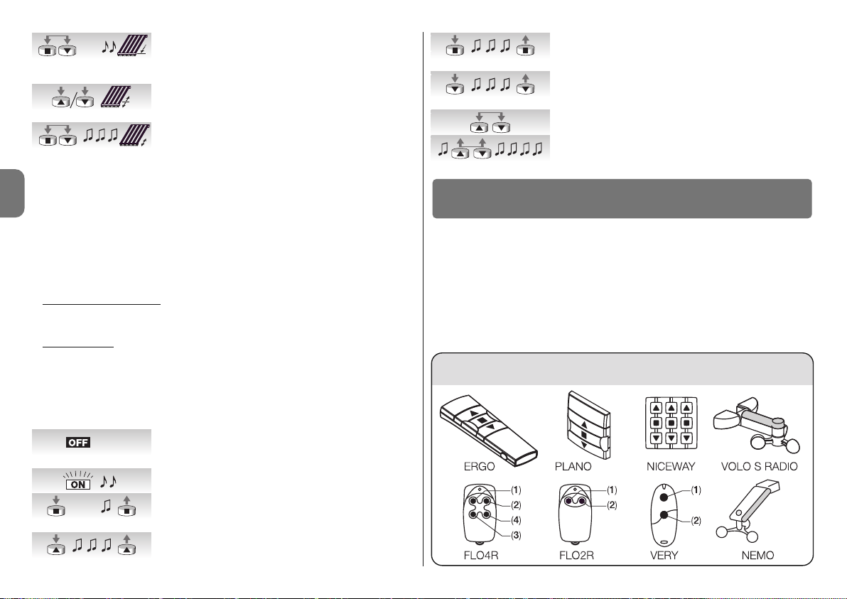
8 – Français
FR
Tableau “A15”
02. Presser et maintenir enfoncées les touches ■▼pen-
dant encore 5 secondes jusqu'à ce que l'on entende 2
bips rapides. Le store est alors automatiquement ac tionné jusqu'à la position “1”.
03. Dans les 5 secondes, utiliser les touches ▼ et ▲ pour
repositionner le store dans la nouvelle position à programmer.
04. Confirmer la position dans les 5 secondes en pressant
simultanément les touches ■ et ▼ de l'émetteur jusqu'à
ce que l'on entende 3 bips et qu'un bref mouvement de
montée/descente se produise.
Note : si la programmation n'est pas confirmée, comme cela est indiqué au point 4, les
modifications sont interrompues et ce sont les programmations précédentes qui sont
maintenues.
Quand on modifie la position “1”, les fonctions “FRT” et “FTC” sont éliminées.
4.4 - Effacement de la mémoire
S'il se révèle nécessaire d'effacer tous les émetteurs et toutes les programmations, on
peut effectuer la séquence d'opérations décrite dans le tableau A14.
L'effacement est possible
:
• avec un émetteur non mémorisé en commençant la procédure à partir du point A ;
• avec un émetteur déjà mémorisé en commençant la procédure à partir du point 1.
On peut effacer
:
• uniquement les émetteurs mémorisés, en s'arrêtant au point 4 ;
• tout (émetteurs, seuil des capteurs, adresse TTBUS, etc.) en poursuivant la procédure
jusqu'au point 6.
––––––––––––––––––––––––––––––––––––––––––––––––––––––––––––––––––––––––––––
Tableau “A14” - Effacement de la mémoire
––––––––––––––––––––––––––––––––––––––––––––––––––––––––––––––––––––––––––––
A. Avec le moteur non alimenté, activer l'entrée pas à pas
(connecter le fil blanc avec le blanc/noir) et la maintenir
active jusqu'à la fin de la procédure.
B. Connecter le moteur à l'alimentation de secteur et atten-
dre les bips initiaux.
01. Presser et maintenir enfoncée la touche ■ d'un émetteur
(environ 5 secondes) jusqu'à ce que l'on entende un bip
puis relâcher la touche ■.
02. Maintenir enfoncée la touche ▲ de l'émetteur jusqu'à ce
que l'on entende 3 bips Relâcher la touche ▲ exactement durant le troisième bip.
03. Maintenir enfoncée la touche ■ de l'émetteur jusqu'à ce
que l'on entende 3 bips. Relâcher la touche ■ exactement durant le troisième bip.
04. Maintenir enfoncée la touche ▼ de l'émetteur jusqu'à ce
que l'on entende 3 bips. Relâcher la touche ▼ exacte-
ment durant le troisième bip.
05. Pour tout effacer : dans les 2 secondes, presser simultanément les touches ▲ et ▼.
06. Relâcher les touches ▲ et ▼ quand on entend le pre-
mier des 5 bips qui confirment l'effacement.
Les moteurs série NEOMAT-T reconnaissent les émetteurs de la série ERGO, PLANO,
NICEWAY, VOLO S RADIO et NEMO (voir chapitre 5.1 “Émetteurs utilisable”).
Par ailleurs, avec des procédures spécifiques de mémorisation des émetteurs, il est possible d'associer à chaque touche de l'émetteur une commande particulière (voir chapitre 5.2
“Programmation des émetteurs en mode I et en mode II”).
Attention : pour les programmations, utiliser uniquement les émetteurs mémorisés
en mode I.
5
Approfondissements
P. P.
5s...
5s...
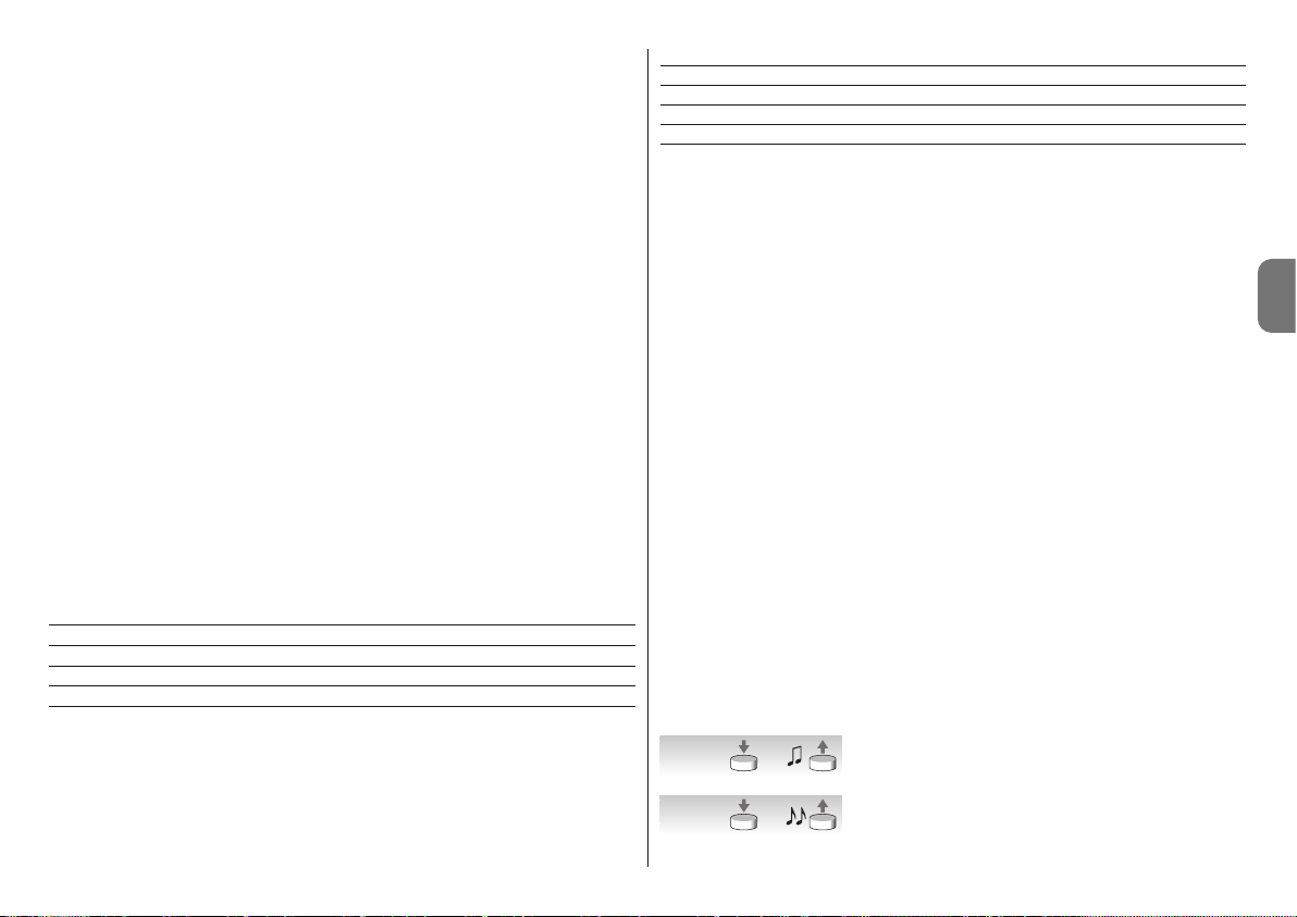
Français – 9
FR
5.1 - Émetteurs utilisables
Le tableau A15 indique les émetteurs qui peuvent être utilisés ainsi que leur type de
codage.
––––––––––––––––––––––––––––––––––––––––––––––––––––––––––––––––––––––––––––
Tableau “A15” - Émetteurs
• ERGO1 - ERGO4 - ERGO6 • PLANO1 - PLANO4 - PLANO6 - PLANO TIME • VOLO S
RADIO • NEMO • NICEWAY (toute la ligne) • FLO1R - FLO2R - FLO4R • VERY VR •
––––––––––––––––––––––––––––––––––––––––––––––––––––––––––––––––––––––––––––
5.2 - Mémorisation des émetteurs en mode I et mode II
Les tableaux “A1” et “A2” décrivent la procédure de mémorisation des émetteurs en
“mode I” où une commande précise est attribuée à chaque touche : touche ▲ (1) = “montée” ; touche ■ (2) = “arrêt” ; touche ▼ (3) = “descente”.
Il est possible de mémoriser les émetteurs aussi en “mode II”, qui permet une plus grande
flexibilité de l'utilisation des touches des émetteurs. Sur le même moteur NEOMAT-T, Il est
possible de mémoriser les émetteurs aussi bien en mode I qu'en mode II.
5.2.1 - Mode I
En mode I, la commande associée aux touches de l'émetteur est fixe : la touche ▲ (1)
commande la “montée” ; la touche ■ (2) commande “l'arrêt” ; la touche ▼ (3) commande
la “descente”, une éventuelle touche 4 commande “l’arrêt”.
En mode I, on effectue une unique phase de mémorisation pour chaque émetteur et un
seul emplacement est occupé dans la mémoire. Durant la mémorisation en mode I, la
touche pressée n'a pas d'importance.
Pour mémoriser ou effacer les émetteurs en mode I, voir les tableaux A1 et A2.
Touche Commande
Touche ▲ ou 1 Montée
Touche ■ ou 2 Arrêt
Touche ▼ ou 3 Descente
Touche 4 Arrêt
5.2.2 - Mode II
En mode II, on peut associer à chaque touche de l'émetteur l'une des 4 commandes possibles : 1 = pas à pas ; 2 = montée-arrêt ; 3 = descente-arrêt ; 4 = arrêt. En mode II, on
effectue une phase de mémorisation pour chaque touche et chacune d'elle occupe un
emplacement de mémoire. Durant la mémorisation en mode II, la touche pressée est
mémorisée. Si l'on souhaite attribuer une autre commande à une autre touche du même
émetteur, il faut procéder à une nouvelle mémorisation.
N° Commande
1 Pas à pas (montée-arrêt-descente-arrêt, etc.) ;
2 Montée - arrêt (montée-arrêt-montée-arrêt, etc.) ;
3 Descente - arrêt (descente-arrêt-descente-arrêt, etc.) ;
4 Arrêt.
5.2.3 - Exemple de mémorisation mixte en mode I et en mode II
En exploitant de manière opportune les mémorisations en mode I et en mode II, on peut
créer des commandes de groupe comme dans l'exemple illustré sur la fig. F.
• L'émetteur T1 (Ergo1) mémorisé en mode I sur A1 et A2 commande la montée, l'arrêt ou la
descente simultanément de A1 et A2, la montée, l'arrêt ou la descente de A1 et A2, A3 ou A4.
• L'émetteur T2 (Plano1) mémorisé en mode I seulement sur A3 commande la montée,
l'arrêt ou la descente seulement d'A3.
• L'émetteur T3 (Planotime) mémorisé en Mode I seulement sur A4 commande la montée,
l'arrêt ou la descente seulement de A4.
• L'émetteur T4 (WM001C) mémorisé en mode II (pas à pas) commande seulement A4.
• L'émetteur T5 (WM003G) mémorisé en mode I pour commander avec le groupe 1 sur
A1 et A2, avec le groupe 2 sur A3 et avec le groupe 3 sur A4 commande la montée, l'arrêt ou la descente de A2 et A2, A3 ou A4.
• L'émetteur T6 (Flo4R) mémorisé en mode II sur A4 (touches 1 et 3), sur A5 (touche 2) et
sur A6 (touche 4), commande la montée et la descente d'A4, ou l'ouverture de la porte
de garage A5 ou l'ouverture du portail automatique A6.
ATTENTION :
• Avec un émetteur mémorisé en mode II, il n'est pas possible d'effectuer la programmation de certaines fonctions (direction du mouvement, temps de travail, etc.) si, pour
cette programmation, il est nécessaire de presser des touches différentes, telles que la
touche ■ et la touche ▲.
• Avec un émetteur mémorisé en mode II, on ne peut pas utiliser les commandes de
“groupe multiple”.
Quand un ou plusieurs émetteurs ont déjà été mémorisés, il est possible d'en activer d'autres en mode II en procédant comme l'indique le tableau A16.
––––––––––––––––––––––––––––––––––––––––––––––––––––––––––––––––––––––––––––
Tableau “A16” - Mémorisation d'autres émetteurs en mode II
––––––––––––––––––––––––––––––––––––––––––––––––––––––––––––––––––––––––––––
01. Presser et maintenir enfoncée la touche à mémoriser du
nouvel émetteur (pendant environ 5 secondes) jusqu'à
ce que l'on entende un bip, puis relâcher la touche.
02. Dans les 5 secondes qui suivent, presser et maintenir
enfoncée la touche 5 d'un émetteur existant déjà mémorisé (environ 5 secondes) jusqu'à ce que l'on entende 2
bips, puis relâcher la touche.
5s.
nouveau
5s.
existant
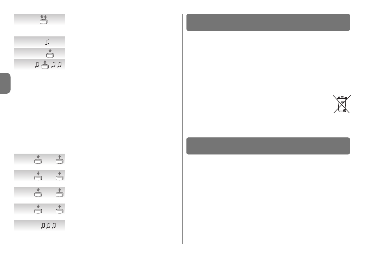
10 – Français
FR
03. Dans les 5 secondes qui suivent, commencer à presser
la touche de l'ancien émetteur un nombre de fois égal à
la commande voulue : 1 = “pas à pas” 2 = “montée” 3 =
“descente” 4 = “arrêt”.
04. Au bout d'environ 3 secondes, on entendra un nombre
de bips égal à la commande sélectionnée.
05. Dans les 2 secondes qui suivent, presser la même tou che du nouvel émetteur.
06. Relâcher la touche quand on entend le premier des 3
bips qui confirment la mémorisation.
Si au point 5, on n'entend pas un nombre de bips égal à la commande désirée, il suffit de
ne presser aucune touche et d'attendre quelques secondes pour terminer la programmation sans aucune mémorisation.
Note : Si la mémoire est pleine (14 émetteurs), 6 bips indiqueront que l'émetteur ne peut
pas être mémorisé.
Il est possible de mémoriser de manière simple un nouvel émetteur en maintenant les
caractéristiques de l'ancien émetteur en suivant la procédure du tableau A17. Le nouvel
émetteur ainsi mémorisé héritera des caractéristiques de l'ancien, c'est-à-dire que si l'ancien était mémorisé en mode I, le nouveau fonctionnera lui aussi en mode I, si l'ancien était
mémorisé en mode II, la touche du nouvel émetteur sera associée à la même commande
que l'ancien.
––––––––––––––––––––––––––––––––––––––––––––––––––––––––––––––––––––––––––––
Tableau “A17” - Mémorisation d'autres émetteurs
––––––––––––––––––––––––––––––––––––––––––––––––––––––––––––––––––––––––––––
01. Presser et maintenir enfoncée la touche à mémoriser du
nouvel émetteur pendant au moins 3 secondes, puis
relâcher la touche.
02. Presser et maintenir enfoncée la touche déjà mémorisée
de l'ancien émetteur pendant au moins 3 secondes, puis
relâcher la touche.
03. Presser et maintenir enfoncée la touche à mémoriser du
nouvel émetteur pendant au moins 3 secondes, puis
relâcher la touche.
04. Presser et maintenir enfoncée la touche déjà mémorisée
de l'ancien émetteur pendant au moins 3 secondes, puis
relâcher la touche.
05. On entendra 3 bips qui confirment la mémorisation du
nouvel émetteur.
Note : Si la mémoire est pleine (14 émetteurs), 6 bips indiqueront que l'émetteur ne peut
pas être mémorisé.
Ce produit fait partie intégrante de l’automatisme et doit donc être mis au rebut avec
cette dernière.
Comme pour l’installation, à la fin de la durée de vie de ce produit, les opérations de
démantèlement doivent être effectuées par du personnel qualifié.
Ce produit est constitué de différents types de matériaux : certains peuvent être recyclés,
d’autres doivent être mis au rebut. Informez-vous sur les systèmes de recyclage ou de
mise au rebut prévus par les normes en vigueur dans votre région pour cette catégorie de
produit.
Attention ! – certains composants du produit peuvent contenir des substances polluantes
ou dangereuses qui pourraient avoir des effets nuisibles sur l’environnement et sur la santé
des personnes s’ils n’étaient pas adéquatement éliminés.
Comme l’indique le symbole ci-contre, il est interdit de jeter ce produit avec les
ordures ménagères. Procéder à la « collecte différenciée » des composants
pour leur traitement conformément aux méthodes prescrites par les normes
locales en vigueur ou restituer le produit au vendeur lors de l’achat d’un nouveau produit équivalent.
Attention ! – les règlements locaux en vigueur peuvent prévoir de lourdes sanctions en
cas d’élimination prohibée de ce produit.
❏ Après l'alimentation, le moteur n'émet pas aucun bip et l'entrée pas à pas
ne commande aucun mouvement.
Contrôler que le moteur est alimenté à la tension de secteur prévue, si l'alimentation est
correcte, il y a probablement une panne grave et le moteur doit être réparé par le service
après-vente.
❏ Après une commande le moteur ne bouge pas.
• Si juste avant il fonctionnait encore, la protection thermique pourrait être intervenue, il
suffit d'attendre quelques minutes que le moteur refroidisse.
• Vérifier si l'entrée “pas à pas” fonctionne en unissant pendant un instant les conducteurs
blanc et noir/blanc.
• Vérifier qu'il y a au moins un émetteur mémorisé en contrôlant qu'à l'allumage le moteur
émet des bips brefs.
• Vérifier qu'il y a “communication” entre l'émetteur et le moteur en maintenant enfoncée
la touche ■ (2) d'un émetteur (mémorisé ou pas) pendant au moins 5 secondes ; si on
entend un bip, cela signifie que le moteur reçoit le signal de l'émetteur, donc il faut passer à la dernière vérification ; sinon, effectuer la vérification qui suit.
7
Que faire si... petit guide en cas de problème !
6
Mise au rebut du produit
>3s.
nouveau
>3s.
existant
>3s.
nouveau
>3s.
existant
1- 4
nouveau
1- 43s.
nouveau

Français – 11
FR
Caractéristiques techniques des moteurs tubulaires NEOMAT-MT
et NEOMAT-LT
• Tension d'alimentation et fréquence : voir données techniques sur l'étiquette de
chaque modèle.
• Courant et puissance : voir données techniques sur l'étiquette de chaque modèle.
• Couple et vitesse : voir données techniques sur l'étiquette de chaque modèle.
• Diamètre du moteur : NEOMAT-MT = 45 mm ; NEOMAT-LT = 58 mm
• Précision (résolution) du fin de course électronique : supérieure à 0,55 ° (selon la
version de NEOMAT-T).
• Précision des positions des arrêts de fin de course : classe 2 (± 5%).
• Résistance mécanique : conforme à EN 14202.
• Temps de fonctionnement continu : maximum 4 minutes.
• Indice de protection : IP 44.
• Température de fonctionnement : -20 ÷ +55 °C
• Longueur câble de connexion : 3 m
• Tension signaux (pas à pas, TTBUS, etc.) : Environ 24 V
• Seuils capteur vent (anémomètre) : 5 équivalents à environ 5, 10, 15, 30 ou 45 km/h
(avec anémomètres VOLO ou VOLOS)
• Seuils capteur soleil : 5 équivalents à environ 5, 10, 15, 30 ou 45 klx (avec VOLO-S)
• Longueur câbles signaux (pas à pas, TTBUS, etc.) : maximum 30 m en cas de proxi-
mité avec d'autres câbles, sinon 100 m
• Fréquence récepteur radio : 433,92 MHz
• Codage récepteur radio : 52 bits à code tournant FLOR et FLOR+INFO
• Nombre d'émetteurs mémorisables : 14, y compris au maximum 3 capteurs clima-
tiques VOLO-S-Radio
• Portée des émetteurs : estimée à 150 m en espace libre et à 20 m à l'intérieur des bâtiments (*)
Notes :
– (*) La portée des émetteurs peut être influencée par d’autres dispositifs fonctionnant à
proximité à la même fréquence que l’émetteur (par exemple écouteurs radio, systèmes
d’alarme, etc.), provoquant des interférences avec le récepteur. En cas de fortes interférences, Nice ne peut offrir aucune garantie sur la portée réelle de ses dispositifs radio.
– Toutes les caractéristiques techniques indiquées se réfèrent à une température
ambiante de 20 °C (± 5 °C).
– NICE s.p.a. se réserve le droit d’apporter des modifications au produit à tout moment si
elle le jugera nécessaire, en garantissant dans tous les cas le même bon fonctionnement
et le type d’utilisation prévus.
• Vérifier l'émission correcte du signal radio de l'émetteur avec cet essai empirique : presser une touche et appuyer la LED à l'antenne d'un appareil radio quelconque (de préférence de type économique) allumé et réglé sur la bande FM à la fréquence de 108,5 Mhz
ou la plus proche possible ; on devrait entendre un léger bruit avec pulsation grésillante.
• Vérifier, en pressant lentement, une à la fois, toutes les touches de l'émetteur, si aucune
commande un mouvement du moteur, cela signifie que cet émetteur n'est pas mémorisé.
❏ Après une commande par radio, on entend 6 bips et la manœuvre ne
démarre pas.
La radiocommande n'est pas synchronisée, il faut répéter la mémorisation de l'émetteur.
❏ Après une commande, on entend 10 bips puis la manœuvre démarre.
L'autodiagnostic des paramètres mémorisés a détecté une anomalie quelconque (les
positions, l'adresse TTBUS, le seuil du vent sont erronés) ; contrôler et éventuellement
reprogrammer.
❏ En montée, avant d'atteindre la position prévue (pos. “0”, pos. “1”), le mo teur s'arrête puis tente de redémarrer à trois reprises.
Cela peut être normal : en montée, quand un effort excessif est détecté, le moteur s'éteint
pendant 1 seconde environ puis réessaie de terminer la manœuvre ; vérifier s'il y a des
obstacles qui empêchent le mouvement.
❏ En descente, avant d'atteindre la position prévue (pos. “1”, pos. “I”), le
mo teur s'arrête.
Cela peut être normal : en descente, quand un effort excessif est détecté, le moteur
s'éteint ; vérifier s'il y a des obstacles qui empêchent le mouvement.
❏ Le moteur ne démarre qu'avec une commande “par action maintenue”.
Si les positions “0” et “1” n'ont pas été programmées, le mouvement du moteur en montée et en descente ne s'effectue qu'avec une commande par action maintenue. Programmer les positions “0” et “1”.
❏ Le moteur s’actionne correctement en montée, mais seulement avec une
commande à action maintenue en descente.
L'autodiagnostic des paramètres mémorisés a détecté une anomalie dans la position du
moteur. Commander le store jusqu’à la conclusion de toute la manœuvre de montée.
12 – Français
FR
DÉCLARATION CE DE CONFORMITÉ
Note - Le contenu de cette déclaration de conformité correspond à ce qui est déclaré dans la dernière révision disponible du document officiel, déposé au siège de Nice S.p.a., avant l'impression de ce guide. Le texte ici présent a
été réadapté pour des raisons d’édition.
Numéro : 223/Neomat T Révision : 3
Je soussigné Luigi Paro en qualité d’Administrateur Délégué, déclare sous mon entière responsabilité que le produit :
Nom producteur : NICE s.p.a.
Adresse : Via Pezza Alta, 13, Z.I. Rustignè, 31046 - Oderzo (TV) Italie
Type : Opérateur tubulaire pour stores dans un caisson avec logique de commande incorporée et récepteur radio
Modèles : Neomat MT, Neomat LT
Accessoires : Radiocomandi série Ergo, Plano, NiceWay, VOLO-S-Radio Anémomètres VOLO, VOLO-S
Est conforme à ce qui est prévu par la directive communautaire suivante :
• DIRECTIVE 1999/5/CE DU PARLEMENT EUROPÉEN ET DU CONSEIL du 9 mars 1999 concernant les équipe-
ments hertziens et les équipements terminaux de télécommunication et la reconnaissance mutuelle de leur conformité, selon les normes harmonisées suivantes :
- Protection de la santé : EN 50371:2002
- Compatibilité électromagnétique : EN 301 489-1 V1.8.1:2008; EN 301 489-3 V1.4.1:2002
- Sécurité électrique : EN 60950-1:2006
- Spectre radio : EN 300 220-2 V2.1.2:2007
De plus, il est conforme à ce qui est prévu par les directives communautaires suivantes, telles qu’elles sont modifiées
par la directive 93/68/CEE du conseil du 22 juillet 1993 :
• 2006/95/CE DIRECTIVE 2006/95/CE DU PARLEMENT EUROPÉEN ET DU CONSEIL du 12 décembre 2006
concernant le rapprochement des législations des États membres relatives au matériel électrique destiné à être utilisé dans certaines limites de tension, selon les normes harmonisées suivantes : EN 60335-1:2002 + A1:2004 +
A11:2004 + A12:2006 + A2:2006 + A13:2008 ; EN 60335-2-97:2006 + A11:2008 ; EN50366:2003 + A1:2006
• DIRECTIVE 2004/108/CE DU PARLEMENT EUROPÉEN ET DU CONSEIL du 15 décembre 2004 concernant le
rapprochement des législations des États membres relatives à la compatibilité électromagnétique et abrogeant la
directive 89/336/CEE, selon les normes suivantes : EN 55014-1:2006 ; EN 55014-2:1997 + A1:2001 ; EN 610003-2:2006 ; EN 61000-3-3:2007
Oderzo, 28 juillet 2009
Luigi Paro
(Administrateur Délégué)

Español – 1
ES
ESPAÑOL
Instrucciones originales
¡ATENCIÓN! - El presente manual contiene instruccio-
nes importantes de seguridad para la INSTALACIÓN
y el USO del producto; conserve estas instrucciones.
¡ATENCIÓN! - La instalación incorrecta puede provo-
car heridas graves. Por tal razón, durante el trabajo
se recomienda respetar escrupulosamente todas las
instrucciones de instalación mencionadas en este
manual.
¡ATENCIÓN! - Es importante respetar estas instruccio-
nes para garantizar la seguridad de las personas.
• Los motores de la serie NEOMAT-T, en las versiones
NEOMAT-MT de Ø 45 mm y NEOMAT-LT de Ø 58 mm,
están destinados para la automatización del movimiento
de toldos con cofre; cualquier otro empleo es consi-
derado inadecuado y está prohibido!
• Los motores han sido diseñados para uso residencial;
se ha previsto un tiempo de funcionamiento continuo
máximo de 4 minutos.
• Al elegir el tipo de motor de acuerdo con su aplicación,
se deberá considerar el par nominal y el tiempo de funcionamiento indicados en la placa de características.
• El diámetro mínimo del tubo de enrollamiento en que
puede instalarse es 52 mm para NEOMAT-MT, con
pares de hasta 35 Nm, 60 mm para NEOMAT-MT con
pares mayores que 35 Nm y 70 mm para NEOMAT-LT.
• La instalación debe ser hecha por personal técnico respetando las normas de seguridad.
• Antes de la instalación hay que alejar todos los cables
eléctricos innecesarios y desactivar todos los mecanismos superfluos para el funcionamiento motorizado.
• Los componentes móviles del motor deben protegerse
si se lo instala a una altura inferior a 2,5 m.
Advertencias y precauciones
de seguridad
• La distancia en horizontal entre el toldo completamente
abierto y cualquier objeto fijo debe ser de 0,4 m como
mínimo.
• El cable de alimentación de PVC, suministrado junto con
los motores de la serie NEOMAT-T, sirve para su instalación en interiores; para un uso en exteriores es necesario proteger todo el cable con un tubo de aislamiento, o
bien solicitar el cable específico tipo S05RN-F.
• El motor tubular no debe sufrir aplastamientos, golpes,
caídas ni debe tener contacto con líquidos de ningún
tipo; no perfore ni aplique tornillos en el motor tubular;
véase la fig. 1.
• El interruptor de mando debe estar colocado en una
posición desde donde pueda verse el elemento que
acciona, pero lejos de las piezas móviles y a una altura
de 1,5 m como mínimo.
• No modifique ninguna parte salvo que esté previsto en
estas instrucciones; los trabajos de este tipo pueden
causar solamente desperfectos; NICE no es responsable de los daños que deriven de productos modificados.
• Diríjase a personal técnico capacitado para el mantenimiento o las reparaciones.
• Mantenga las personas lejos de la persiana o del toldo
cuando estén en movimiento.
• No accione el toldo si en las cercanías se están realizando trabajos, por ejemplo: limpieza de cristales; en el
caso de accionamiento automático, desconecte también la alimentación eléctrica.
• No permita que los niños jueguen con los mandos y
mantenga los controles remotos lejos de su alcance.
• Si estuvieran instalados, controle a menudo los muelles
de equilibrado o el desgaste de los cables.
¡ATENCIÓN! - Los sensores climáticos de las series Volo y
Nemo no deben considerarse dispositivos de seguridad
que eliminan las averías del toldo por efecto de la lluvia o
del viento fuerte (en efecto, un banal corte de energía
eléctrica haría imposible el movimiento automático del
toldo). Los sensores climáticos deben considerarse parte de un automatismo útil para la protección del toldo y
para que su uso sea más cómodo.
Nice no se asume ninguna responsabilidad por daños
materiales provocados por eventos atmosféricos no
detectados por los sensores.
¡ATENCIÓN! - En el caso de lluvia, para que no se acumu-
le agua, es necesario recoger el toldo de brazo si la pen-
diente es menor del 25% o del valor recomendado por el
fabricante.
¡ATENCIÓN! - Si se forma hielo, el funcionamiento podría
averiar la persiana o el toldo.
¡ATENCIÓN! - Algunas etapas de la programación aprove-
chan los topes mecánicos del toldo para bloquear la
carrera del motor; por dicho motivo, es indispensable
elegir el motor con el par más adecuado para las características del toldo, teniendo en cuenta el esfuerzo efectivo y evitando montar motores muy potentes.
Los motores de la serie NEOMAT-T, en las versiones NEOMAT-MT Ø 45 mm y NEOMAT-LT Ø 58 mm, son motores
eléctricos equipados con reducción de revoluciones, que
en un extremo terminan con un eje en el que se pueden
montar las ruedas de arrastre (véase la fig. 2). El motor se
instala introduciéndolo en el interior del tubo del toldo; el
motor mueve el toldo en subida o en bajada.
La central incorporada en el motor dispone de un sistema
de fin de carrera electrónico de alta precisión, que puede
detectar constantemente la posición del toldo/persiana.
Con una operación de programación se memorizan los
límites del movimiento, es decir toldo cerrado y toldo abierto (más las probables posiciones intermedias); después de
cada mando el movimiento se detendrá automáticamente
al alcanzar esas posiciones. El fin de carrera electrónico
puede compensar posibles estiramientos del toldo (función
“CAT”) garantizando el cierre perfecto del cajón y evitando
que el toldo quede flojo cuando esté abierto.
Los motores de la serie NEOMAT-T incorporan la función
de reducción de par (función “RDC”) que disminuye el 50%
aproximadamente el par del motor poco antes de que el
toldo se cierre para no tensar excesivamente la lona. Esta
función se puede desactivar con un transmisor (véase
4.3.2.) o con las unidades de programación TTP y OTTView, que también permiten seleccionar la reducción en 3
niveles: al 50, al 40 o al 30% aproximadamente de par.
Las funciones CAT y RDC han sido estudiadas para simular el comportamiento atento y diligente de una persona
que mueve el toldo manualmente.
Los motores serie NEOMAT-T incorporan un radiorreceptor
1
Descripción del producto

2 – Español
ES
que trabaja a una frecuencia de 433.92 MHz con tecnología rolling code, para garantizar niveles de seguridad elevados. Para cada motor es posible memorizar hasta 14
radiomandos de la serie ERGO, PLANO y NICEWAY, véase
la fig. 3, que permiten el mando a distancia del motor, o
bien hasta 3 radiosensores de viento y sol “VOLO S
RADIO” o “NEMO” que accionan automáticamente el mo tor según la situación climática.
Es posible programar los fines de carrera y algunas funciones adicionales directamente desde los transmisores y un
tono de aviso (“Bip”) le guiará en las diferentes etapas. Hay
disponible una entrada para accionar los motores también
con un botón exterior (con función Paso a Paso), o bien
por medio de Bus “TTBUS”. Como alternativa al botón
Paso a Paso, en TTBUS es posible conectar la fotocélula
específica F210S para detectar la presencia de posibles
obstáculos e impedir así la maniobra de bajada. Para más
informaciones sobre las conexiones, consulte el manual de
instrucciones de la fotocélula F210S.
En la entrada de los sensores climáticos se pueden conectar los sensores opcionales de viento, sol y lluvia que activan automáticamente el motor cuando las condiciones climáticas así lo requieren.
En los motores NEOMAT-T pueden programarse funciones
particulares que resuelven problemas específicos (fig. A):
– FRT: esta función permite tensar la lona, una cantidad
programable, después de que el toldo se ha abierto completamente. Permite evitar que la lona quede floja cuando
el toldo está abierto. Para más detalles, véase la tabla
A10.
– FTC: permite motorizar toldos que se mantienen tensos
mediante un mecanismo de enganche automático, por
ejemplo los toldos verandas. Para más detalles, véase la
tabla A11.
¡ATENCIÓN! - La instalación incorrecta puede provocar heridas graves.
Prepare el motor con la siguiente secuencia de operaciones (véase la fig. 4 - 5 - 6):
01. Introduzca la corona del fin de carrera (E) en el motor
2
Instalación
(A) hasta que entre en el casquillo del fin de carrera (F)
correspondiente, haciendo coincidir las dos ranuras;
empuje hasta que haga tope, tal como indicado en la
fig. 5-(1).
02. Introduzca la rueda de arrastre (D) en el eje del motor.
03. En NEOMAT-MT, fije la rueda de arrastre con la aran-
dela seeger a presión. En NEOMAT-LT, fije la rueda de
arrastre con la arandela y la tuerca M12.
04. Introduzca el motor ensamblado de esta manera en el
tubo en que se enrolla la persiana/toldo hasta introducir también el extremo de la corona (E). Fije el anillo de
arrastre (D) al tubo de enrollamiento mediante tornillos
M4x10 para que el motor no se desplace ni se deslice
axialmente (fig. 6).
05. Por último, bloquee la cabeza del motor al soporte
respectivo (C), con el distanciador por medio de los
clips o del pasador hendido (B).
2.1 - Conexiones eléctricas
¡ATENCIÓN! - En las conexiones de los motores hay
que instalar un dispositivo omnipolar de desconexión de la red eléctrica con distancia entre los contactos de 3 mm como mínimo (interruptor o enchufe
y tomacorriente, etc.).
¡ATENCIÓN! - Respete escrupulosamente las conexio-
nes previstas; si tuviera dudas, no pruebe inútilmente
sino que consulte las fichas técnicas disponibles
tam bién en la página web “www.niceforyou.com”.
Una conexión incorrecta puede provocar averías o
situaciones peligrosas.
El cable para las conexiones eléctricas de los motores
NEOMAT-MT y NEOMAT-LT dispone de 6 conductores; 3
conductores (etiqueta amarilla) sirven para la alimentación
de red y los otros 3 conductores (etiqueta violeta) sirven
para las señales de mando.
Para hacer las conexiones eléctricas ver la fig. B. Los dispositivos de conexión no se entregan con el producto.
2.1.1 - Alimentación de red (Marrón + Azul +
Amarillo/Verde)
La alimentación eléctrica a la tensión de red debe conectarse a los conductores: Marrón (Fase); Azul (Neutro) y
Amarillo/Verde (Tierra). ¡ATENCIÓN! - No conecte por
ningún motivo la alimentación de red (230V o 120V) a
los otros conductores.
2.1.2 - Entrada “Paso a Paso” (Blanco +
Negro/Blanco)
Para accionar la automatización manualmente, es posible
conectar un simple contacto de un botón entre los conductores Blanco (entrada Paso a Paso) y Negro/Blanco
(Común); el modo de funcionamiento sigue la secuencia:
subida-stop-bajada-stop.
Si se mantiene pulsado el botón durante más de 3 segundos (pero menos de 10 seg.) siempre se activa una maniobra de subida (la que corresponde al botón ▲ de los transmisores). Si se mantiene pulsado el botón durante más de
10 segundos, siempre se activa una maniobra de bajada
(correspondiente al botón ▼ ). Esta solución puede ser útil
para "sincronizar" varios motores hacia la misma maniobra,
independientemente del estado en que se encuentren.
2.1.3 - Entrada “TTBUS” (Blanco + Negro/Blanco)
El “TTBUS” es un Bus desarrollado para poder controlar,
individualmente, motores o centrales de mando, hasta 100
dispositivos, sencillamente conectándolos en paralelo utilizando solamente 2 conductores. Más informaciones se
encuentran en las instrucciones en los productos compatibles con "TTBUS".
En la entrada TTBUS es posible conectar los programadores TTP, TTI u O-ViewTT que permiten simplificar las operaciones de programación y de gestión de las instalaciones; para más informaciones, consulte los manuales cor respondientes.
2.1.4 - Entrada “Fotocélula F210S” (Blanco +
Negro/Blanco)
En la entrada “Fotocélula F120S” es posible conectar la
fotocélula específica F210S para detectar la presencia de
posibles obstáculos e impedir la maniobra de bajada. Más
informaciones sobre las conexiones pueden consultarse
en el manual de instrucciones de la fotocélula F210 S.
¡ATENCIÓN! - Las entradas Paso a Paso, TTBUS y
F120S son alternativas entre sí, porque utilizan físicamente los mismos conductores Blanco + Negro/Blan co; por consiguiente, es posible utilizar un tipo de en trada por vez.
2.1.5 - Sensores climáticos (Negro/Blanco +
Naranja/Blanco)
En la entrada “Sensores climáticos” (entre Común y la en trada Sensores climáticos) puede conectarse un sencillo

Español – 3
ES
Toldo completamente
cerrado (Pos. “0”)
Toldo abierto (Pos. “1”)
Posición intermedia (“I”)
Posición de inicio de la reducción de par RDC durante el movimiento de cierre (posición no programable)
Posición “2” para
función “FRT”
Posición de desenganche “S”
para toldos que
se mantienen tensos mediante un
mecanismo de
enganche automático
“0”
“A”
“2”
“1”
“S”
E
sensor de viento (anemómetro), o bien un sensor especial
de viento-sol-lluvia.
Si se utilizan los sensores de viento es posible conectar a
un mismo sensor hasta 5 motores o centrales, utilizando
una conexión en paralelo (respetar la polaridad de las
señales).
¡Atención! - No obstante sea posible, no se aconseja la
conexión de un único sensor sol a varios motores. En efecto, aunque los umbrales de los distintos motores estén
regulados en el mismo valor, cada motor ejecuta una medición propia y los movimientos automáticos de los toldos no
son simultáneos.
Para mover varios motores simultáneamente es necesario
utilizar sensores con una regulación de umbral propia,
como por ejemplo los modelos Volo ST, Volo S Radio y
Nemo.
2.2 - Dirección de salida del cable (fig. C)
(Sólo para el modelo NEOMAT-LT) – Si se deseara modi-
ficar la dirección de salida del cable, es suficiente: 01.
Extraer la protección, tirándola hacia afuera. 02. Plegar el
cable hacia la dirección deseada. 03. Introducir la protec-
ción presionándola con fuerza en su alojamiento.
2.3 - Conector y cable de alimentación
(Sólo para el modelo NEOMAT-MT) – Las informaciones
de este capítulo están destinadas exclusivamente para el
personal técnico del servicio de asistencia.
¡ATENCIÓN! - Si el cable de alimentación estuviera
averiado deberá sustituírselo por uno similar que puede pedirse al fabricante o a su servicio de asistencia.
Si fuera necesario desconectar el motor del cable de alimentación, proceda de la siguiente manera (fig. D): a) - Gi re el casquillo hasta hacer coincidir el chaflán con uno de
los dientes de enganche, entonces desenganche. b) - Re pita la operación para el otro diente. c) - Pliegue el cable
hacia adentro y quite la protección girándola con delicadeza hacia afuera. d) - Extraiga el conector tirando de él.
Los motores tubulares de la serie NEOMAT disponen de
un sistema de fin de carrera electrónico; la central electrónica interrumpe el movimiento cuando el toldo llega a las
posiciones de cierre y de apertura programadas. Dichas
posiciones se memorizan con una programación oportuna
que se debe hacer directamente con el motor instalado y
con el toldo montado completamente.
(fig. E) Si aún no fueron memorizadas las posiciones “0”
(toldo cerrado) y “1” (toldo abierto) es posible accionar
igualmente el motor, pero el movimiento se ejecutará sólo
en modo hombre muerto.
También es posible programar las siguientes posiciones:
• La posición intermedia “I” para la apertura parcial del tol-
do. Esta posición se puede programar incluso en un
segundo momento.
• La posición “2” necesaria para activar la función “FRT”
que permite tensar la lona cuando el toldo está completamente abierto.
• La función “FTC” para la automatización de toldos con
un mecanismo de enganche automático.
3
Regulaciones

4 – Español
ES
La programación se divide en 3 partes:
1. Memorización de los transmisores
2. Programación de las posiciones “0” y “1”
3. Programaciones opcionales
Para que un transmisor pueda accionar un motor de la serie NEOMAT-T es necesario efectuar la memorización, tal como indicado en la tabla A1.
ATENCIÓN:
• Todas las secuencias de memorización son por tiempo, es decir que deben efectuarse dentro de los límites de tiempo previstos.
• Con transmisores que prevean varios “grupos”, antes de proceder con la memorización,
hay que elegir el grupo del transmisor al que asociar el motor.
• La memorización por radio se puede realizar en todos los receptores que se encuentran
en el radio de alcance del transmisor y, por eso, es oportuno mantener alimentado sólo
el receptor que debe ser programado.
Es posible comprobar si hay transmisores memorizados en el motor; a tal fin, es suficiente controlar la cantidad de tonos de aviso que se emiten en el momento del encendido del
motor:
- 2 tonos de aviso prolongados = Ningún transmisor memorizado.
- 2 tonos de aviso cortos = Hay transmisores memorizados.
4.1 - Programación de los transmisores
––––––––––––––––––––––––––––––––––––––––––––––––––––––––––––––––––––––––––––
Tabla “A1” - Memorización del primer transmisor (en Modo I)
––––––––––––––––––––––––––––––––––––––––––––––––––––––––––––––––––––––––––––
01. Conecte el motor a la alimentación de red, se oirán in -
me diatamente 2 tonos de aviso largos.
02. Antes de transcurridos 5 segundos, pulse y mantenga
pulsado el botón ■ del transmisor a memorizar (unos 3
segundos).
03. Suelte el botón ■ cuando oiga el primero de los 3 tonos
de aviso que confirman la memorización.
Para memorizar otros transmisores, véase la tabla A2
Cuando se haya memorizado uno o varios transmisores, es posible memorizar otros transmisores, tal como indicado en la tabla A2.
4
Programaciones
––––––––––––––––––––––––––––––––––––––––––––––––––––––––––––––––––––––––––––
Tabla “A2” - Memorización de otros transmisores (en Modo I)
––––––––––––––––––––––––––––––––––––––––––––––––––––––––––––––––––––––––––––
01. Pulse y mantenga pulsado el botón ■ del nuevo transmi-
sor (unos 5 segundos) hasta oír un tono de aviso; después suelte el botón ■ .
02. Pulse lentamente 3 veces el botón ■ de un transmisor
viejo y memorizado.
03. Pulse de nuevo el botón ■ del nuevo transmisor y suéltelo al oír el primero de los 3 tonos de aviso que confirman la memorización.
Nota: si la memoria está llena (14 transmisores) se oirán 6 tonos de aviso y el transmisor
no podrá ser memorizado.
4.2 - Programación de las posiciones “0” y “1”
Para programar las posiciones hay que utilizar un telemando memorizado en Modo I. Hasta que no se memoricen en la central las posiciones “0” y “1”, los movimientos se efectúan en modo hombre muerto. En un comienzo, la dirección del motor no está definida, pero
cuando se completa el punto 1 de la tabla “A3”, la dirección del motor se asigna automáticamente a los botones de los telemandos.
Para la programación de las posiciones 0 y 1, siga el procedimiento indicado en la tabla
“A3”:
––––––––––––––––––––––––––––––––––––––––––––––––––––––––––––––––––––––––––––
Tabla “A3” - Programación de las posiciones “0” y “1”
––––––––––––––––––––––––––––––––––––––––––––––––––––––––––––––––––––––––––––
01. Pulse y mantenga pulsado el botón ▲ o el botón ▼ de
un telemando memorizado hasta que el toldo se cierre
por completo y el motor se detenga automáticamente.
02. Pulse y mantenga pulsado el botón ▼ que hace bajar el
toldo.
03. Suelte el mando ▼ cuando el toldo haya llegado a la
posición deseada (“1”). Si fuera necesario, regule la po sición con los botones ▼ y ▲.
04. Mantenga pulsado el botón ■ del transmisor hasta oír un
tono de aviso (transcurridos alrededor de 5 segundos).
05. Suelte y pulse de nuevo durante otros 5 segundos el
botón ■ hasta oír 4 tonos de aviso rápidos.
06. Pulse el botón ▼ hasta que 3 tonos de aviso y un breve
movimiento de subida y bajada indiquen que la cota ha
sido memorizada.
3s...
5s...
x 3
nuevo
viejo
nuevo
5s...
5s...

Español – 5
ES
4.3 - Programaciones opcionales
Todas las programaciones opcionales están disponibles sólo tras haber programado las
posiciones “0” y “1”.
4.3.1 - Memorización de la posición intermedia “I”
Si se memoriza una posición intermedia “I”, es posible mover el toldo hacia la posición “I”
pulsando simultáneamente los 2 botones ▲▼del transmisor.
Para memorizar la posición intermedia, lleve a cabo el procedimiento indicado en la tabla “A4”:
––––––––––––––––––––––––––––––––––––––––––––––––––––––––––––––––––––––––––––
Tabla “A4” - Programación de la posición intermedia “I”
––––––––––––––––––––––––––––––––––––––––––––––––––––––––––––––––––––––––––––
01. Utilizando los botones ▲ ■ ▼ de un telemando, coloque
el toldo donde se desea memorizar la posición “I”.
02. Mantenga pulsado el botón ■ hasta oír un tono de aviso
(transcurridos unos 5 segundos).
03. Suelte y pulse de nuevo durante otros 5 segundos el
botón ■ hasta oír 4 tonos de aviso rápidos.
04. Pulse juntos los botones ▼ ▲ hasta que 3 tonos de avi-
so indiquen que la cota ha sido memorizada.
4.3.2 - Desactivación o reactivación de la Reducción de par durante el cierre
(RDC)
La reducción de par es una función que reduce el par de tracción en alrededor del 50% un poco
antes del cierre completo del toldo en el cofre, a fin de evitar una tensión excesiva de la lona.
Esta función se activa automáticamente después de la programación de las cotas 0 y 1 (la programación siempre se ejecuta con la fuerza máxima) pero puede desactivarse (o reactivarse).
Nota - la función RDC no se activa automáticamente si la programación de las posiciones
se hace con los programadores TTP, TTI y O-ViewTT; en estos casos, si se deseara, la función se puede activar manualmente.
––––––––––––––––––––––––––––––––––––––––––––––––––––––––––––––––––––––––––––
Tabla “A5” - Desactivación o reactivación de la reducción de par (RDC)
––––––––––––––––––––––––––––––––––––––––––––––––––––––––––––––––––––––––––––
01. Mantenga pulsado el botón ■ de un transmisor memori-
zado hasta oír un tono de aviso (después de unos 5
segundos).
02. Suelte y pulse de nuevo durante otros 5 segundos el
botón ■ hasta oír 4 tonos de aviso rápidos.
03. Oprima el pulsador ■ hasta que suenen los tonos de avi-
so: 3 tonos de aviso (bip) indican que la RDC está activa
(cierre con par reducido); 5 tonos de aviso (bip) indican
que la RDC no está activa (cierre con par máximo).
4.3.3 - Cancelación de las posiciones
Para modificar las posiciones memorizadas con anterioridad, primero hay que borrarlas y
después se puede volver a programar las nuevas posiciones
––––––––––––––––––––––––––––––––––––––––––––––––––––––––––––––––––––––––––––
Tabla “A6” Borrado de la posición intermedia “I”
––––––––––––––––––––––––––––––––––––––––––––––––––––––––––––––––––––––––––––
01. Mantenga pulsado el botón ■ de un transmisor memori-
zado hasta oír un tono de aviso (después de unos 5
segundos).
02. Suelte y pulse de nuevo durante otros 5 segundos el
botón ■ hasta oír 4 tonos de aviso rápidos.
03. Pulse simultáneamente los botones ▼ ▲ hasta que 5
tonos de aviso indiquen que la posición intermedia ha
sido cancelada.
––––––––––––––––––––––––––––––––––––––––––––––––––––––––––––––––––––––––––––
Tabla “A7” - Borrado de las posiciones “0” y “1”
––––––––––––––––––––––––––––––––––––––––––––––––––––––––––––––––––––––––––––
01. Mantenga pulsado el botón ■ de un transmisor memori-
zado hasta oír un tono de aviso (después de unos 5
segundos).
02. Suelte y pulse de nuevo durante otros 5 segundos el
botón ■ hasta oír 4 tonos de aviso rápidos.
03. Pulse el botón ▼ hasta que 5 tonos de aviso señalen
que las posiciones “0” y “1” han sido canceladas.
ATENCIÓN: Tras haber cancelado la posiciones “0” y “1” el toldo se moverá en modalidad
hombre presente y habrá que memorizar las posiciones nuevas.
Nota: la posición intermedia “I” y la función RDC programadas no se cancelan. Si usted
desea cancelar todo (incluidos los códigos de los transmisores) consulte la tabla “A14”.
4.3.4 - Programación del nivel del sensor climático “viento”
Si a la entrada “sensores” se le conecta un sensor de viento "VOLO" o "VOLO S", se activa la protección “viento”, es decir que el toldo se cierra automáticamente si el viento superara el nivel programado. Si el nivel es superado durante más de 3 segundos, se activa un
mando equivalente al botón ▲ y se bloquea cualquier otro movimiento hasta que el viento
vuelva por debajo del nivel programado durante 1 minuto como mínimo. Es posible seleccionar el nivel de activación entre 5 niveles: 1=5Km/h, 2=10Km/h, 3=15Km/h, 4=30Km/h
y 5=45Km/h. (el nivel de fábrica es el N°3).
Si se utilizara el sensor “VOLO ST” o los sensores radio Volo S Radio y Nemo, los umbrales de activación del sensor del viento estarán programados directamente en el sensor
(véanse las instrucciones correspondientes).
Para modificar el nivel programado:
5s...
5s...
5s...
5s...
5s...
5s...
(...)
5s...
5s...

6 – Español
ES
––––––––––––––––––––––––––––––––––––––––––––––––––––––––––––––––––––––––––––
Tabla “A9” - Cambio del nivel de activación de la protección “viento”
––––––––––––––––––––––––––––––––––––––––––––––––––––––––––––––––––––––––––––
01. Mantenga pulsado el botón ■ de un transmisor memori-
zado (alrededor de 5 segundos) hasta oír un tono de aviso; posteriormente, suelte el botón ■ .
02. Pulse lentamente el botón ▲ la cantidad de veces (1, 2,
3, 4 ó 5) equivalente al nivel deseado.
03. Después de un instante, se oirá una cantidad de tonos
de aviso equivalente al nivel requerido.
04. Pulse y suelte el botón ■ para confirmar.
Si en el punto 3 no se oyera la cantidad de tonos de aviso equivalente al nivel deseado, no
pulse ningún botón y espere algunos segundos para terminar sin cambiar el nivel.
4.3.5 - Programación del nivel del sensor climático “sol”
Si a la entrada “sensores” se le conecta un sensor de sol "VOLO-S", se activa el automatismo “sol”, es decir la bajada automática del toldo, si el “sol” supera el nivel programado.
Si el nivel es superado durante más de 2 segundos, se activa un mando equivalente al
botón ▼; si el “sol” descendiera por debajo del nivel programado durante 15 minutos, se
activa un mando equivalente al botón ▲.
Es posible seleccionar el nivel de activación “sol” entre 5 niveles: 1=5Klux, 2=10Klux,
3=15Klux, 4=30Klux y 5=45Klux (de fábrica el nivel es el N°3).
––––––––––––––––––––––––––––––––––––––––––––––––––––––––––––––––––––––––––––
Tabla “A10” - Cambio del nivel de accionamiento del automatismo “sol”
––––––––––––––––––––––––––––––––––––––––––––––––––––––––––––––––––––––––––––
Si se utilizara el sensor “VOLO ST” o los sensores radio Volo S Radio y Nemo, los umbrales de activación del sensor del sol estarán programados directamente en el sensor (véanse las instrucciones correspondientes).
01. Mantenga pulsado el botón ■ de un transmisor memorizado (alrededor de 5 segundos) hasta oír un tono de aviso; posteriormente, suelte el botón ■ .
02. Pulse lentamente el botón ▼ la cantidad de veces (1, 2,
3, 4 ó 5) equivalente al nivel deseado.
03. Después de un instante, se oirá una cantidad de tonos
de aviso equivalente al nivel requerido.
04. Pulse y suelte el botón ■ para confirmar.
Si en el punto 3 no se oyera la cantidad de tonos de aviso equivalente al nivel deseado, no
pulse ningún botón y espere algunos segundos para terminar sin cambiar el nivel.
4.3.6 - Cambiar la dirección de activación en caso de lluvia
Si se utilizara un sensor de lluvia Nemo WSRT, cuando el sensor detecte la presencia de
lluvia, enviará la información a los motores y se accionará un movimiento hacia la dirección
programada (de fábrica está programada la dirección “subida”).
Para modificar la dirección de activación del sensor lluvia:
01. Mantenga presionado el pulsador ■ de un transmisor memorizado hasta oír un tono
de aviso (después de alrededor de 5 segundos); posteriormente, suelte el pulsador.
02. Pulse lentamente el mismo pulsador ■ otras 3 veces.
03. Pulse el pulsador con la dirección deseada (subida o bajada); entonces, el motor emi-
tirá 3 tonos de aviso = nueva dirección memorizada.
Los movimientos automáticos provocados por el sensor “sol” pueden desactivarse con un
mando de "Sol OFF" enviado desde un transmisor que incorpora dicha función (Ergo 4,
Plano 4, WM004G) y pueden reactivarse con un mando de “Sol ON”.
A los movimientos automáticos provocados por el sensor “sol” pueden unirse, en cualquier momento, los mandos enviados por el usuario con un transmisor normal; estos últimos prevalecen sobre los mandos del sensor “sol
”, en el modo descrito en el siguien-
te ejemplo: si el toldo está en posición “1” (que se alcanzó automáticamente al superarse
el umbral “sol”) y poco después el usuario acciona la recogida del toldo a la posición “0”,
posteriormente, aunque el sistema continúe detectando la superación del umbral “sol” el
toldo no se mueve (éste queda en la posición accionada por el usuario).
El “ciclo automático” interrumpido por el mando manual se reactiva cuando el nivel de
intensidad luminosa se coloca por debajo del umbral (por lo general al atardecer).
4.3.7 - Programación de la función “FRT”
Después de haber programado las posiciones "0" y "1", si se desea, es posible programar
la posición “2” que activa la función de levantamiento de la lona FRT.
Para programar la posición “2”, lleve a cabo el procedimiento indicado en la tabla “A11”.
5s...
5s...
x 1 = 5 Km/h
x 2 = 10 Km/h
x 3 = 15 Km/h
x 4 = 30 Km/h
x 5 = 45 Km/h
x 1 = 5 Km/h
x 2 = 10 Km/h
x 3 = 15 Km/h
x 4 = 30 Km/h
x 5 = 45 Km/h
x 1 = 5 Klux
x 2 = 10 Klux
x 3 = 15 Klux
x 4 = 30 Klux
x 5 = 45 Klux
x 1 = 5 Klux
x 2 = 10 Klux
x 3 = 15 Klux
x 4 = 30 Klux
x 5 = 45 Klux

Español – 7
ES
––––––––––––––––––––––––––––––––––––––––––––––––––––––––––––––––––––––––––––
Tabla “A11” - Programación de la posición “2”
––––––––––––––––––––––––––––––––––––––––––––––––––––––––––––––––––––––––––––
01. Mantenga pulsado el botón ■ de un transmisor memori-
zado hasta oír un tono de aviso (después de unos 5
segundos).
02. Pulse y mantenga pulsados los botones ■▼durante
otros 5 segundos hasta oír 2 tonos de aviso rápidos.
Entonces, el toldo se colocará automáticamente en la
posición del fin de carrera inferior (posición “1”).
03. Antes de 5 segundos utilice los botones ▼ y ▲ para
colocar el toldo en la posición de recogida deseada.
04. Confirme antes de 5 segundos la posición, pulsando el
botón ■ del transmisor hasta oír 3 tonos de aviso. Posteriormente, el toldo se colocará en la posición del fin de
carrera inferior (posición “1”) programada.
Nota: si no se confirma la programación como descrito en el punto 4, las modificaciones
no serán memorizadas y se mantendrán las programaciones anteriores.
Si después de haber programado esta función se desea eliminarla, hay que llevar a cabo
el procedimiento indicado en la tabla A13, saltando el paso N°3, es decir, sin modificar la
posición “1”.
Cuando se programa la posición “2”, la central electrónica calcula automáticamente la diferencia entre la posición “2” y la posición “1”, para que, en cada mando de bajada, el toldo
baje hasta la posición mayor y después recuperar la lona hasta la posición menor de las 2.
4.3.8 - Programación de la función “FTC”
Después de haber programado las posiciones “0” y “1”, si se desea, es posible programar
la posición “S” que activa la función “FTC” para la automatización de toldo que incorporen
un mecanismo de enganche automático. Para que el mecanismo funcione correctamente,
es necesario que la posición “1” esté programada algunos centímetros después del punto
de enganche, a fin de que durante la subida del punto “1” se produzca el enganche, y que
la posición “S” esté programada algunos centímetros después del punto de enganche,
para que la subida desde el punto “S” se produzca libremente.
Para programar la posición “S”, lleve a cabo el procedimiento indicado en la tabla “A12”:
––––––––––––––––––––––––––––––––––––––––––––––––––––––––––––––––––––––––––––
Tabla “A12” - Programación de la Posición de Desenganche “S”
––––––––––––––––––––––––––––––––––––––––––––––––––––––––––––––––––––––––––––
01. Mantenga pulsado el botón ■ de un transmisor memori-
zado hasta oír un tono de aviso (después de unos 5
segundos).
02. Pulse y mantenga pulsados los botones ■▼durante
otros 5 segundos hasta oír 2 tonos de aviso rápidos.
Entonces, el toldo se coloca automáticamente en la
posición “1”.
03. Antes de 5 segundos utilice los botones ▼ y ▲ para
colocar el toldo en la posición de desenganche “S” (inferior a la posición “1”).
04. Confirme antes de 5 segundos la posición, pulsando
simultáneamente los botones ▼ y ▲ del transmisor hasta oír 3 tonos de aviso. Entonces, el toldo se coloca au tomáticamente en la posición “0”.
Nota: si no se confirma la programación como descrito en el punto 4, las modificaciones
no serán memorizadas y se mantendrán las programaciones anteriores.
Si después de haber programado esta función se desea eliminarla, hay que llevar a cabo
el procedimiento indicado en la tabla A13, saltando el paso N°3, es decir, sin modificar la
posición “1”.
4.3.9 - Modificación de la posición “1”
Para desplazar la posición “1”, lleve a cabo el procedimiento indicado en la tabla “A13”:
––––––––––––––––––––––––––––––––––––––––––––––––––––––––––––––––––––––––––––
Tabla “A13” - Modificación de la posición “1”
––––––––––––––––––––––––––––––––––––––––––––––––––––––––––––––––––––––––––––
01. Mantenga pulsado el botón ■ de un transmisor memori-
zado hasta oír un tono de aviso (después de unos 5
segundos).
02. Pulse y mantenga pulsados los botones ■▼durante
otros 5 segundos hasta oír 2 tonos de aviso rápidos.
Entonces, el toldo se coloca automáticamente en la po sición “1”.
03. Antes de 5 segundos utilice los botones ▼ y ▲ para
colocar el toldo en la nueva posición a programar.
04. Confirme antes de 5 segundos la posición, pulsando
simultáneamente los botones ■▼del transmisor hasta
oír 3 tonos de aviso y un breve movimiento de subida y
bajada.
si no se confirma la programación tal como descrito en el punto 4, las modificaciones no
quedan memorizadas y se mantienen las programaciones anteriores.
Modificando la posición “1” también se eliminan las funciones “FRT” y “FTC”.
5s...
5s...
5s...
5s...
5s...
1
S
5s...

8 – Español
ES
Tabla “A15”
4.4 - Borrado de la memoria
Si fuera necesario borrar los transmisores y las programaciones, se puede ejecutar la
secuencia indicada en la tabla A14.
La cancelación es posible
:
• con un transmisor no memorizado, empezando el procedimiento desde el punto A.
• con un transmisor memorizado, empezando el procedimiento desde el punto 1.
Se pueden borrar
:
• sólo los transmisores memorizados, terminando en el punto 4.
• todos (transmisores, nivel sensores, dirección TTBUS, etc.), completando el procedimiento hasta el punto 6.
––––––––––––––––––––––––––––––––––––––––––––––––––––––––––––––––––––––––––––
Tabla “A14” - Borrado de la memoria
––––––––––––––––––––––––––––––––––––––––––––––––––––––––––––––––––––––––––––
A. Con el motor no alimentado, active la entrada paso a
paso (conecte el hilo Blanco al hilo Blanco/Negro) y
manténgala activa hasta el final del proc dimiento.
B. Conecte el motor a la alimentación de red y espere los
tonos de aviso iniciales.
01. Pulse y mantenga pulsado el botón ■ de un transmisor
(unos 5 segundos) hasta oír un tono de aviso; después
suelte el botón ■ .
02. Mantenga pulsado el botón ▲ de un transmisor hasta oír
3 tonos de aviso; suelte el botón ▲ exactamente durante el tercer tono de aviso.
03. Mantenga pulsado el botón ■ del transmisor hasta oír 3
tonos de aviso; suelte el botón ■ exactamente durante
el tercer tono de aviso.
04. Mantenga pulsado el botón ▼, de un transmisor hasta
oír 3 tonos de aviso; suelte el botón ▼, exactamente
durante el tercer tono de aviso.
05. Para borrar todo: antes de 2 segundos, pulse ambos
botones ▲ y ▼.
06. Suelte los botones ▲ y ▼, cuando oiga el primero de los
5 tonos de aviso que confirman la cancelación.
Los motores de la serie NEOMAT-T reconocen los transmisores de la serie ERGO, PLANO,
NICEWAY, VOLO S RADIO y NEMO (véase el capítulo 5.1 “Transmisores que pueden utilizarse”).
Con procedimientos oportunos de memorización de los transmisores es posible asociar a
cada botón del transmisor un mando particular (véase el capítulo 5.2 “Programación de
los transmisores en Modo I y Modo II”).
Atención: para las programaciones, utilice únicamente los transmisores memorizados en Modo I.
5.1 - Transmisores que pueden utilizarse
En la tabla A15 se indican los transmisores que pueden utilizarse con el tipo de codificación correspondiente.
––––––––––––––––––––––––––––––––––––––––––––––––––––––––––––––––––––––––––––
Tabla “A15” - Transmisores
• ERGO1 - ERGO4 - ERGO6 • PLANO1 - PLANO4 - PLANO6 - PLANO TIME • VOLO S
RADIO • NEMO • NICEWAY (toda la línea) • FLO1R - FLO2R - FLO4R • VERY VR •
––––––––––––––––––––––––––––––––––––––––––––––––––––––––––––––––––––––––––––
5
Otras informaciones
P. P.
5s...

Español – 9
ES
5.2 - Memorización de los transmisores en Modo I y Modo II
En las tablas “A1” y “A2” se describe la memorización de los transmisores en “Modo I”,
donde a cada botón se asigna un mando: botón ▲ (1) = “Subida”; botón ■ (2) = “Parada”;
botón ▼ (3) = “Bajada”.
También es posible memorizar los transmisores en “Modo II”; dicho modo permite mayor
flexibilidad de uso de los botones de los transmisores. En el mismo motor NEOMAT-T se
pueden memorizar tanto transmisores en Modo I como en Modo II.
5.2.1 - Modo I
En Modo I el mando asociado a los botones del transmisor es fijo: el botón ▲ (1) acciona
la “Subida”; el botón ■ (2) acciona la “Parada”; el botón ▼ (3) acciona la “Bajada”, un posible botón 4 acciona la “Parada”.
En Modo I se ejecuta una única etapa de memorización para cada transmisor y se ocupa
un solo lugar en la memoria. Durante la memorización en Modo I no es importante el botón
que se pulsa. Para memorizar o borrar los transmisores en Modo I, véanse las tablas A1 y
A2.
Botón Mando
Botón ▲ o bien 1 Subida
Botón ■ o bien 2 Parada
Botón ▼ o bien 3 Bajada
Botón 4 Parada
5.2.2 - Modo II
En Modo II es posible asociar a cada botón del transmisor uno de los 4 mandos posibles:
1 = Paso a Paso; 2 = Subida-Parada; 3 = Bajada-Parada,
4 = Parada En Modo II se ejecuta una etapa de memorización para cada botón y cada uno
ocupa un lugar en la memoria. Durante la memorización en Modo II se memoriza el botón
pulsado. Si se desea asignar a otro botón del mismo transmisor otro mando es necesario
realizar otra memorización.
N° Mando
1 Paso a Paso (subida-parada-bajada-parada…)
2 Subida-Parada (subida-parada-subida-parada…)
3 Bajada-Parada (bajada-parada-bajada-parada…)
4 Parada
5.2.3 - Ejemplo de memorización mixta Modo I y Modo II
Aprovechando oportunamente las memorizaciones en Modo I y Modo II, es posible crear
mandos de grupo como en el ejemplo indicado en la fig. F.
• El transmisor T1 (Ergo1), memorizado en Modo I en A1 y A2, acciona la subida, la parada o la bajada simultáneamente en A1 y en A2.
• El transmisor T2 (Plano1) memorizado en Modo I sólo en A3 acciona la subida, la parada o la bajada sólo de A3.
• El transmisor T3 (Planotime) memorizado en Modo I sólo en A4 acciona la subida, la
parada o la bajada sólo de A4.
• El transmisor T4 (WM001C) memorizado en Modo II (Paso a Paso) acciona sólo A4.
• El transmisor T5 (WM003G), memorizado en Modo I, para accionar, con el grupo 1 en
A1 y A2, con el grupo 2 en A3 y con el grupo 3 en A4, acciona la subida, la parada o la
bajada de A1 y A2, A3 o bien A4.
• El transmisor T6 (Flo4R) memorizado en Modo II en A4 (botones 1 y 3) en A5 (botón 2) y
en A6 (botón 4) acciona la subida y la bajada de A4, o bien la apertura de la puerta de
garaje A5, o bien la apertura de la puerta automática A6.
ATENCIÓN:
• Con un transmisor memorizado en Modo II no es posible efectuar la programación de
algunas funciones (posiciones, niveles, etc.) dado que en esta secuencia se requiere
pulsar botones diferentes, por ejemplo el botón ■ y el botón ▲.
• Con un transmisor memorizado en Modo II no es posible utilizar los mandos de “grupo
múltiple”.
Cuando se hayan memorizado uno o varios transmisores, es posible memorizar otros
transmisores en Modo II, tal como indicado en la tabla A16.
––––––––––––––––––––––––––––––––––––––––––––––––––––––––––––––––––––––––––––
Tabla “A16” - Memorización de otros transmisores en Modo II
––––––––––––––––––––––––––––––––––––––––––––––––––––––––––––––––––––––––––––
01. Pulse y mantenga pulsado el botón a memorizar del
nuevo transmisor (unos 5 segundos) hasta oír un tono
de aviso; después suelte el botón.
02. Antes de 5 segundos, pulse y mantenga pulsado el botón
de un transmisor viejo y memorizado (unos 5 segundos)
hasta oír 2 tonos de aviso, después suelte el botón.
03. Antes de 5 segundos empiece a pulsar el mismo botón
del transmisor viejo la cantidad de veces equivalente al
mando deseado: 1=“paso a paso” 2= “subida” 3= “bajada” 4= “parada”.
04. Después de alrededor de 3 segundos se oirá una cantidad
de tonos de aviso equivalente al mando seleccionado.
05. Antes de 2 segundos, pulse el mismo botón del nuevo
transmisor.
06. Suelte el botón cuando oiga el primero de los 3 tonos de
aviso que confirman la memorización.
Si en el punto 5 no se oye la cantidad de tonos de aviso equivalente al mando deseado,
no pulse ningún botón y espere algunos segundos para terminar la programación sin ninguna memorización.
5s.
nuevo
5s.
viejo
1- 4
nuevo
1- 43s.
nuevo

10 – Español
ES
Nota: si la memoria está llena (14 transmisores) se oirán 6 tonos de aviso y el transmisor
no podrá ser memorizado.
Siguiendo el procedimiento de la tabla A17 es posible memorizar de manera sencilla un
nuevo transmisor, manteniendo las características del transmisor viejo. El nuevo transmisor memorizado adquirirá las características del transmisor viejo, es decir que si el viejo
estaba memorizado en Modo I, también el nuevo funcionará en Modo I y si el viejo estaba
memorizado en Modo II, también el botón del nuevo transmisor será asociado al mismo
mando del viejo.
––––––––––––––––––––––––––––––––––––––––––––––––––––––––––––––––––––––––––––
Tabla “A17” - Memorización de otros transmisores
––––––––––––––––––––––––––––––––––––––––––––––––––––––––––––––––––––––––––––
01. Pulse y mantenga pulsado el botón a memorizar del
nuevo transmisor durante 3 segundos como mínimo,
después suelte el botón.
02. Pulse y mantenga pulsado el botón memorizado del viejo transmisor durante 3 segundos como mínimo, después suelte el botón.
03. Pulse y mantenga pulsado el botón a memorizar del
nuevo transmisor durante 3 segundos como mínimo,
después suelte el botón.
04. Pulse y mantenga pulsado el botón memorizado del viejo transmisor durante 3 segundos como mínimo, después suelte el botón.
05. Se oirán 3 tonos de aviso que confirman la memorización del nuevo transmisor.
Nota: si la memoria está llena (14 transmisores) se oirán 6 tonos de aviso y el transmisor
no podrá ser memorizado.
Este producto forma parte integrante de la automatización y, por consiguiente, debe
eliminarse junto con ésta.
Al igual que para las operaciones de instalación, también al final de la vida útil de este producto, las operaciones de desguace deben ser efectuadas por personal experto.
Este producto está formado de varios tipos de materiales: algunos pueden reciclarse y
otros deben eliminarse. Infórmese sobre los sistemas de reciclaje o de eliminación previstos por las normativas vigentes locales para esta categoría de producto.
¡Atención! – algunas piezas del producto pueden contener sustancias contaminantes o
peligrosas que, si se las abandona en el medio ambiente, podrían provocar efectos perjudiciales para el mismo medio ambiente y para la salud humana.
Tal como indicado por el símbolo de aquí al lado, está prohibido arrojar este
producto a los residuos urbanos. Realice la “recogida selectiva” para la eliminación, según los métodos previstos por las normativas vigentes locales, o
bien entregue el producto al vendedor cuando compre un nuevo producto
equivalente.
¡Atención! – las reglas locales pueden prever sanciones importantes en el caso de eliminación abusiva de este producto.
❏ Después de la alimentación, el motor no emite ningún tono de aviso y la
entrada Paso a Paso no acciona ningún movimiento.
Controle que el motor esté alimentado con la tensión de red prevista; si la alimentación es
correcta, es probable que haya una avería grave y entonces habrá que hacer reparar el
motor por el centro de asistencia.
❏ Después de un mando el motor no se mueve.
• Si antes funcionaba, podría haberse desconectado la protección térmica; hay que
esperar algunos minutos hasta que el motor se enfríe.
• Controle si la entrada “paso a paso” funciona, uniendo por un instante los conductores
Blanco y Negro/Blanco.
• Controle que haya un transmisor memorizado como mínimo, controlando que al encenderse el motor emita tonos de aviso cortos.
• Controle que haya “comunicación” entre el transmisor y el motor, manteniendo pulsado
el botón ■ (2) de un transmisor (memorizado o no) durante 5 segundos como mínimo;
si se oyera un tono de aviso, significa que el motor recibe la señal del transmisor y pase
al último control; en caso contrario, efectúe el próximo control.
• Controle que la emisión de la señal radio del transmisor sea correcta con este ensayo:
7
Qué hacer si... ¡pequeña guía en caso de problemas!
6
Eliminación del producto
>3s.
nuevo
>3s.
viejo
>3s.
nuevo
>3s.
viejo

Español – 11
ES
Características técnicas de los motores tubulares NEOMAT-MT y
NEOMAT-LT
• Tensión de alimentación y frecuencia: Véanse datos técnicos en la etiqueta de cada
modelo
• Corriente y potencia: Véanse datos técnicos en la etiqueta de cada modelo
• Par y velocidad: Véanse datos técnicos en la etiqueta de cada modelo
• Diámetro del motor: NEOMAT-MT = 45mm; NEOMAT-LT = 58mm
• Precisión (resolución) del fin de carrera electrónico: mayor que 0,55° (depende de la
versión de NEOMAT-T)
• Precisión de las posiciones de los topes de fin de carrera: Clase 2 (± 5%)
• Resistencia mecánica: según EN 14202
• Tiempo de funcionamiento continuo: Máximo 4 minutos
• Clase de protección: IP 44
• Temperatura de funcionamiento: -20°÷ +55°C
• Longitud del cable de conexión: 3 m
• Tensión de las señales (paso a paso, TTBUS …): 24 V aprox.
• Niveles sensor viento (anemómetro): 5, equivalentes a 5, 10, 15, 30 ó 45 Km/h (con
anemómetros VOLO o VOLOS )
• Niveles sensor sol: 5, equivalentes a 5, 10, 15, 30 ó 45 Klux (con VOLOS )
• Longitud de los cables de las señales (paso a paso, TTBUS…): máximo 30 m si
está cerca de otros cables, por el contrario 100 m.
• Frecuencia radiorreceptor: 433.92 MHz
• Codificación radiorreceptor: 52 Bit rolling code FLOR y FLOR+INFO
• N° transmisores memorizables: 14 con un máximo de 3 sensores climáticos VOLO-S-
Radio
• Alcance de los transmisores: estimado en 150 m al aire abierto y en 20m en el interior
de edificios (*)
Notas:
– (*) El alcance de los transmisores puede verse influenciado por otros dispositivos que
funcionan en las cercanías con la misma frecuencia del transmisor (por ejemplo auriculares con radio, sistemas de alarma, etc.), provocando interferencias con el receptor. En
casos de interferencias fuertes, Nice no puede ofrecer ninguna garantía sobre el alcance real de sus dispositivos radio.
– Todas las características técnicas indicadas se refieren a una temperatura ambiental de
20°C (± 5°C).
– Nice S.p.a. se reserva el derecho de modificar el producto en cualquier momento, man-
teniendo las mismas funcionalidades y el mismo uso previsto.
pulse un botón y apoye el led sobre la antena de un aparato radio común (es mejor si es
económico) encendido y sintonizado en la banda FM en la frecuencia de 108,5Mhz o lo
más cerca posible de dicha frecuencia; se tendría que escuchar un ligero graznido.
• Controle todos los botones del transmisor, pulsándolos lentamente uno a la vez; si ninguno acciona un movimiento del motor, significa que dicho transmisor no está memorizado.
❏ Después de un mando por radio se oyen 6 tonos de aviso y la maniobra no
arranca.
El radiomando está desincronizado; hay que repetir la memorización del transmisor.
❏ Después de un mando se oyen 10 tonos de aviso y después la maniobra
arranca.
El autodiagnóstico de los parámetros en la memoria ha detectado alguna irregularidad
(posiciones, dirección TTBUS, nivel de viento son incorrectos); borre la memoria y pruebe
a repetir las programaciones.
❏ Durante la subida, antes de llegar a la posición prevista (pos. “0”, pos.
“I”), el motor se detiene y se oye que trata de volver a arrancar por 3 veces.
Puede ser normal: durante la subida, cuando se detecta un esfuerzo excesivo, el motor se
apaga durante 1 segundo y luego trata de concluir la maniobra; controle que no haya obstáculos que impidan el movimiento.
❏ Durante la bajada, antes de llegar a la posición prevista (pos. “1”, pos “I”),
el motor se detiene.
Puede ser normal: durante la bajada, cuando se detecta un esfuerzo excesivo, el motor se
apaga; controle que no haya obstáculos que impidan el movimiento.
❏ El motor se mueve sólo en modo hombre muerto.
Si las posiciones “0” y “1” no fueron programadas el movimiento de subida y bajada del
motor se realiza sólo en modo hombre muerto. Programe las posiciones “0” y “1”.
❏ El motor se mueve correctamente en subida, pero en modo “hombre presente” en bajada.
El autodiagnóstico de los parámetros en la memoria ha detectado un desperfecto en la
posición del motor. Accione el toldo hasta completar todo el movimiento de subida.

12 – Español
ES
DECLARACIÓN DE CONFORMIDAD CE
Nota - El contenido de esta declaración corresponde a aquello declarado en la última revisión disponible, antes de la
impresión de este manual, en el documento oficial, depositado en la sede de Nice S.p.a. En este manual, el texto ha
sido readaptado por motivos de impresión.
Número: 223/Neomat T Revisión: 3
El suscrito Luigi Paro, en su carácter de Administrador Delegado, declara bajo su responsabilidad que el producto:
Nombre del fabricante: NICE s.p.a.
Dirección: Via Pezza Alta, 13, Z.I. Rustignè, 31046 - Oderzo (TV) Italia
Tipo: Motorreductor tubular para toldos de cofre con central incorporada y receptor radio
Modelos: Neomat MT, Neomat LT
Accessorios: Radiomandos serie Ergo, Plano, NiceWay, VOLO-S-Radio Anemómetros VOLO, VOLO-S
Satisface los requisitos previstos por las siguientes directivas comunitarias:
• 1999/5/CE DIRECTIVA 1999/5/CE DEL PARLAMENTO EUROPEO Y DEL CONSEJO del 9 de marzo de 1999 rela-
tiva a los equipos radioeléctricos y equipos terminales de telecomunicación y el recíproco reconocimiento de su
conformidad, según las siguientes normas armonizadas:
- Protección de la salud: EN 50371:2002
- Compatibilidad electromagnética: EN 301 489-1 V1.8.1:2008; EN 301 489-3 V1.4.1:2002
- Seguridad eléctrica: EN 60950-1:2006
- Espectro radioeléctrico: EN 300 220-2 V2.1.2:2007
También es conforme con cuanto previsto por las siguientes directivas comunitarias, tal como modificadas por la
Directiva 93/68/CEE del Consejo del 22 de julio de 1993:
• 2006/95/CE DIRECTIVA 2006/95/CE DEL PARLAMENTO EUROPEO Y DEL CONSEJO del 12 de diciembre de
2006 sobre de la aproximación de las legislaciones de los Estados miembros relativas al material eléctrico destinado a ser utilizado dentro de dichos límites de tensión, según las siguientes normas armonizadas: EN 60335-1:2002
+ A1:2004 + A11:2004 + A12:2006 + A2:2006 + A13:2008; EN 60335-2-97:2006 + A11:2008; EN50366:2003 +
A1:2006
• 2004/108/CE DIRECTIVA 2004/108/CE DEL PARLAMENTO EUROPEO Y DEL CONSEJO del 15 de diciembre de
2004 sobre la aproximación de las legislaciones de los Estados miembros relativas a la compatibilidad electromagnética y que abroga la Directiva 89/336/CEE, según las siguientes normas: EN 55014-1:2006; EN 55014-2:1997
+ A1:2001; EN 61000-3-2:2006; EN 61000-3-3:2007
Oderzo, 28 de Julio de 2009
Luigi Paro
(Administrador delegado)

Deutsch – 1
DE
DEUTSCH
Originalanleitungen
ACHTUNG! - Das vorliegende Handbuch enthält
Anweisungen, die für die Sicherheit bei INSTALLATION und BEDIENUNG des Produktes sehr wichtig
sind. Anweisungen aufbewahren.
ACHTUNG! - Eine unkorrekte Installation kann schwe-
re Verletzungen verursachen. Aus diesem Grund
sind bei den verschiedenen Arbeitsschritten alle im
vorliegenden Handbuch enthaltenen Installationsanweisungen genauestens zu befolgen.
ACHTUNG! - Für die Sicherheit von Personen ist es
wichtig, sich an diese Anweisungen zu halten.
• Die Motoren der Serie NEOMAT-T, in den Versionen
NEOMAT-MT mit Ø 45 mm und NEOMAT-LT mit Ø 58
mm sind für die Automatisierung der Sonnenmarkisenbewegung mit Markisenkasten bestimmt; jeder andere
Einsatz ist unsachgemäß und daher untersagt!
• Die Motoren sind für den Gebrauch an Wohnbauten
konstruiert mit maximalem Dauerbetrieb von 4 Minuten.
• Bei der Wahl des Motortyps je nach Anwendung sind
das Drehmoment und die Betriebszeit zu berücksichtigen, die auf dem Datenschild angegeben sind.
• Der Mindestdurchmesser der Rolle, in die der Motor
installiert werden kann, beträgt 52 mm für NEOMAT-MT
mit Drehmomenten bis 35Nm, 60 mm für NEOMAT-MT
mit Drehmomenten über 35Nm und 70 mm für NEOMAT-LT.
• Die Installation muss unter voller Einhaltung der Sicherheitsvorschriften durch technisches Personal ausgeführt
werden.
• Vor der Installation müssen alle nicht notwendigen Elektrokabel entfernt werden; alle für den motorisierten
Betrieb nicht notwendigen Mechanismen müssen deaktiviert sein.
Sicherheitshinweise
und maßnahmen
• Die sich bewegenden Motorteile müssen geschützt sein,
falls der Motor in einer Höhe unter 2,5 m installiert wird.
• Für die Markisen muss der horizontale Abstand zwischen ganz geöffneter Markise und einem beliebigen,
immer vorhandenen Gegenstand mindestens 0,4 m
betragen.
• Das mit den Motoren der Serie NEOMAT-T gelieferte
PVC-Versorgungskabel macht diese für Innenanwendungen geeignet, für Außenanwendungen muss das
ganze Kabel mit einem Isoliermantel geschützt werden
oder es kann das spezielle Kabel des Typs S05RN-F
bestellt werden.
• Den Rohrmotor keinen Quetschungen, Stößen, Stürzen
oder Kontakt mit Flüssigkeiten beliebiger Art unterziehen, nicht lochen und keine Schrauben in der Gesamtlänge des Rohrs anbringen, siehe Abb. 1.
• Der Schalter muss sichtbar, aber fern von den Bewegungsteilen und in einer Höhe von mindestens 1,5 m
angebracht sein.
• Keine Änderungen an keinem Teil ausführen, falls nicht
im vorliegenden Handbuch vorgesehen. Vorgänge dieser Art können nur Betriebsstörungen verursachen.
NICE lehnt jegliche Haftung für Schäden aufgrund geänderter Produkte ab.
• Für Wartung und Reparaturen wenden Sie sich bitte an
technisches Fachpersonal.
• Personen vom Rollladen fern halten, wenn sich dieser
bewegt.
• Die Markise nicht betätigen, wenn Arbeiten wie zum Beispiel Fenster putzen in ihrer Nähe ausgeführt werden;
falls automatisch gesteuert, auch die Stromversorgung
abschalten.
• Kinder nicht mit den Steuervorrichtungen spielen lassen;
die Fernbedienungen außer der Reichweite von Kindern
halten.
• Falls vorhanden, die Ausgleichsfedern und die Abnützung der Seile häufig kontrollieren.
ACHTUNG! - Die Klimawächter der Serie Volo und Nemo
sind nicht als Sicherheitsvorrichtungen zu betrachten,
die Störungen der Markise aufgrund Regen oder starkem Wind beseitigen (ein banaler Stromausfall würde die
automatische Markisenbewegung unmöglich machen).
Die Klimawächter werden als Teil einer Automatisierung
betrachtet, um die Markise zu schützen und die Anwendung komfortabler zu gestalten.
Nice lehnt jede Haftung für Sachschäden ab, die auf-
grund von Wettereinflüssen verursacht werden, die nicht
von den Wächtern erfasst wurden.
ACHTUNG! - Um die Bildung von Wassersäcken bei Re -
gen zu vermeiden, muss die Gelenkarmmarkise aufgerollt werden, wenn die Neigung weniger als 25% oder als
den vom Hersteller empfohlenen Wert beträgt.
ACHTUNG! - Falls sich Eis gebildet hat, könnte der Rollla-
den durch den Betrieb geschädigt werden.
ACHTUNG! - Einige Phasen der Programmierung nützen
die mechanischen Endanschläge des Rollladens zur
Sperre des Motorenhubs; aus diesem Grund ist es
unum gänglich, den Motor mit dem für die Eigenschaften
des Rollladens geeigneten Drehmoment zu wählen, wo bei auch der effektive Kraftaufwand in Betracht gezogen
und zu starke Motoren vermieden werden müssen.
Die Motoren der Serie NEOMAT-T in den Ausführungen
NEOMAT-MT Ø45 mm und NEOMAT-LT Ø58 mm sind EMotoren mit Drehzahlreduzierung, die an einem Ende mit
einer speziellen Welle enden, in welche die Mitnehmräder
eingebaut werden können (siehe Abb. 2). Der Motor wird
durch Einsetzen in das Rohr der Markise installiert; er ist in
der Lage, den Rollladen anzuheben und zu senken.
Die im Motor integrierte Steuerung verfügt auch über ein
elektronisches Endschaltersystem, das die Stellung des
Rollladens ständig und präzise wahrnimmt.
Die Bewegungsgrenzen (Markise geschlossen/geöffnet
und eventuelle Zwischenpositionen) speichert man über
einen Programmierungsvorgang; die Bewegung wird nach
jedem Befehl automatisch bei Erreichung dieser Positionen
stoppen. Dank dem elektronischen Endschalter kann ein
eventuelles Durchhängen des Markisentuchs ausgeglichen
werden (CAT-Funktion), wodurch der einwandfreie Verschluss des Kastens und eine immer gut gespannte, geöffnete Markise gesichert sind.
Um ein zu starkes Ziehen der Stoffbahn zu vermeiden,
wenn die Markise ganz geschlossen ist, verfügen die
Motoren der Serie NEOMAT-T auch über die “RDC”-Drehmomentreduzierungsfunktion, die das Drehmoment des
Motors kurz vor der vollständigen Schließung der Markise
um 50% verringert. Diese Funktion kann durch einen Sen-
1
Beschreibung des Produktes

2 – Deutsch
DE
der (siehe 4.3.2) oder mit den diesbezüglichen Programmierungseinheiten TTP und OTT-View deaktiviert werden,
mit denen auch die 3-Stufen-Reduzierung gewählt werden
kann: 50, 40 oder 30% des Drehmoments.
Mit den Funktionen CAT und RDC soll das aufmerksame
und vorsichtige Verhalten einer Person vorgetäuscht werden, die die Markise von Hand betätigt.
Die Motoren der Serie NEOMAT-T enthalten auch einen
Funkempfänger, der auf einer Frequenz von 433.92 MHz
mit Rolling-Code-Technologie arbeitet, um ein hohes
Niveau an Sicherheit zu gewährleisten. Für jeden Motor
können für die Fernsteuerung des Motors bis zu 14 Sender
der Serien ERGO, PLANO und NICEWAY gespeichert werden; siehe Abb. 3; oder 3 Wind- und Sonnefunksensoren
“VOLO S RADIO” oder “NEMO”, die den Motor je nach
Witterung automatisch steuern.
Die Programmierung der Endschalter und einiger zusätzlicher Funktionen kann direkt über Sender durchgeführt
werden; ein “Biepton” wird die verschiedenen Phasen
anleiten. Weiterhin steht ein Eingang zur Verfügung, um die
Motoren über eine externe Taste (in Schrittbetrieb) oder
über “TTBUS” zu steuern. Als Alternative zur Taste Schrittbetrieb kann an TTBUS eine Photozelle F210S angeschlossen werden, die eventuelle Hindernisse wahrnimmt
und die Abstiegsbewegung verhindert. Für Einzelheiten
wird auf die Anweisungen der Photozelle F210S verwiesen.
Am Eingang der Wetterwächter können zusätzliche Wind-,
Sonne und Regenwächter (Optionals) angeschlossen werden, die den Motor bei Bedarf automatisch aktivieren.
In den NEOMAT-T können auch Sonderfunktionen für spezielle Probleme programmiert werden (Abb. A):
– FRT: mit dieser Funktion kann das Tuch um ein programmierbares Maß aufgerollt werden, nachdem die Markise
ganz geöffnet ist. Ermöglicht es, ein unschönes Durchhängen des Tuchs zu vermeiden, wenn die Markise geöffnet
ist. Siehe die Tabelle A10 für weitere Einzelheiten.
– FTC: dient zur Motorisierung von Markisen, die durch
eine automatische Einspannung gespannt gehalten bleiben, wie zum Beispiel Beschattungs- mit Senkrechtmarkisen. Siehe die Tabelle A11 für weitere Einzelheiten.
ACHTUNG! - Eine unkorrekte Installation kann schwere Verletzungen verursachen.
Den Motor mit folgender Arbeitssequenz vorbereiten (siehe
Abb. 4 - 5 - 6):
01. Den Endschalterkranz (E) auf den Motor (A) stecken,
bis er in der entsprechenden Endschalternutmutter (F)
steckt und die beiden Nuten zusammen treffen; bis
zum Anschlag schieben, wie auf Abb. 5-(1) gezeigt.
02. Das Mitnehmrad (D) auf die Motorwelle stecken.
03. Am NEOMAT-MT muss das Mitnehmrad mit dem See-
gerring durch Druck befestigt werden. Am NEOMATLT muss das Mitnehmrad mit der Unterlegscheibe und
der Mutter M12 befestigt werden.
04. Den so zusammengebauten Motor in die Aufrollrolle
ge ben, bis auch das Ende des Kranzes (E) darin ste ckt. Das Mitnehmrad (D) mit einer Schraube M4x10 so
an der Aufrollrolle befestigen, dass mögliche Schlupfungen oder Längsverschiebungen des Motors nicht
möglich sind, wie in Abb. 6 angegeben.
05. Abschließend den Motorkopf mit den Klammern oder
dem Stift (B) und dem eventuellen Distanzstück an
seiner Halterung (C) befestigen.
2.1 - Elektrische Anschlüsse
ACHTUNG! - In die Motoranschlüsse muss eine allpo-
lige Abschaltvorrichtung vom Stromnetz mit mindestens 3 mm Abstand zwischen den Kontakten eingebaut werden (Trennschalter oder Stecker und Steckdose, usw.).
ACHTUNG! - Die vorgesehenen Anschlüsse genaues-
tens ausführen; im Zweifelsfall keine unnützen Versuche machen, sondern die technischen Blätter zu
Rate ziehen, die auch im Internet unter www.nicefor
you.com zur Verfügung stehen. Ein falscher Ansch luss kann Defekte oder Gefahren verursachen.
Ein falscher Anschluss kann Defekte oder Gefahren verursachen.
Das Kabel für die elektrischen Anschlüsse der Motoren
NEOMAT-MT und NEOMAT-LT hat 6 Leiter; 3 Leiter (gelbes
2
Installation
Etikett) dienen für die Netzstromversorgung und 3 Leiter
(violettes Etikett) für die Steuersignale.
Um die elektrischen Anschlüsse siehe Abb. B. Die Verbindungsvorrichtungen sind mit dem Produkt nicht mitgeliefert.
2.1.1 - Netzstromversorgung (braun + blau +
gelb/grün)
Die elektrische Netzspannungsversorgung muss an folgenden Leitern angeschlossen sein: braun (Phase); blau (Nullleiter) und gelb-grün (Erde). ACHTUNG! - Die Netzstrom-
versorgung (230V oder 120V) keinesfalls an den anderen Leitern anschließen.
2.1.2 - Eingang “Schrittbetrieb”
(weiß + schwarz-weiß)
Um die Automatisierung manuell zu steuern, kann ein einfacher Kontakt für eine Taste zwischen den Leitern weiß
(Eingang Schrittbetrieb) und schwarz-weiß (gemeinsamer
Leiter) angeschlossen werden. Der Betrieb erfolgt nach der
Sequenz: Anstieg-Stopp-Abstieg-Stopp. Wird die Taste
länger als 3 Sekunden (aber weniger als 10) gedrückt
gehalten, aktiviert sich immer eine Anstiegsbewegung (entspricht Taste ▲ der Sender). Wird die Taste länger als 10
Sekunden gedrückt gehalten, aktiviert sich immer eine
Abstiegsbewegung (entspricht Taste ▼). Diese Besonderheit kann nützlich sein, um mehrere Motoren bei derselben
Bewegung unabhängig vom Status, in dem sie sich befinden, zu "synchronisieren”.
2.1.3 - Eingang “TTBUS” (weiß + schwarz-weiß)
Der “TTBUS” wurde entwickelt, um Motoren bzw. Steuerungen einzeln zu kontrollieren; es können bis zu 100 Vorrichtungen kontrolliert werden, indem diese einfach und mit
nur 2 Leitern parallel geschaltet werden. Weitere Auskünfte
sind in den Anweisungen der TTBUS kompatiblen Produkte enthalten. Am Eingang TTBUS können die Programmierer TTP, TTI und O-ViewTT angeschlossen werden, die eine
Vereinfachung der Programmiervorgänge und des Anlagenbetriebs ermöglichen; für weitere Auskünfte wird auf
die jeweiligen Anleitungen verwiesen.
2.1.4 - Eingang “Photozelle F210S”
(weiß + schwarz-weiß)
Am Eingang “Photozelle F120S” kann die spezielle Photozelle F210S angeschlossen werden, die eventuelle Hindernisse wahrnimmt und die Abstiegsbewegung verhindert.
Weitere Auskünfte über die Anschlüsse sind in den Anleitungen der Photozelle F210 S enthalten.

Deutsch – 3
DE
Markise ganz geschlossen (Pos. “0”)
Markise geöffnet (Pos. “1”)
Zwischenposition (“I”)
Position für den Beginn der Drehmomentreduzierung “RDC” während der Schließung (Position nicht
programmierbar).
Position “2” für die
Funktion “FRT”
Ausspannposition
“S” für Markisen,
die durch einen
automatischen
Spannmechanismus gespannt
sind
“0”
“A”
“2”
“1”
“S”
E
ACHTUNG! - Die Eingänge Schrittbetrieb, TTBUS und
F210S sind zueinander alternativ, da sie dieselben Leiter weiß + schwarz-weiß benutzen; daher kann jeweils
nur ein Eingangstyp benutzt werden.
2.1.5 - Wetterwächter (schwarz-weiß + orangefarben-weiß)
Am Eingang “Wetterwächter (zwischen dem Gemeinsamen und dem Eingang Wetterwächter) kann ein einfacher
Windwächter oder ein spezieller Wind-, Sonne- und Re genwächter angeschlossen werden.
Wenn die Windwächter verwendet werden, ist es möglich,
an einen Wächter bis zu 5 Motoren oder Steuerungen an zuschließen, wofür ein Parallelanschluss verwendet wird
(die Polarität der Signale einhalten).
Achtung! - Obwohl dies möglich ist, empfehlen wir, einen
Sonnenwächter nicht an mehrere Motoren anzuschließen.
Wenn die Grenzwerte der einzelnen Motoren auch auf denselben Wert eingestellt wurden, führt jeder Motor eine eigene Messung aus, wodurch die automatischen Bewegungen der Markisen nicht gleich sind.
Um mehrere Motoren gleichzeitig zu bewegen, müssen
Wächter mit einer eigenen Grenzwertregelung verwendet
werden, wie zum Beispiel die Modelle Volo ST, Volo S Ra dio und Nemo.
2.2 - Kabelaustrittsrichtung (Abb. C)
(Nur für Modell NEOMAT-LT) – Wenn man die Kabelaus-
trittsrichtung ändern will, genügt es: 01. Den Schutz nach
außen herauszuziehen. 02. Das Kabel in die gewünschte
Richtung zu biegen. 03. Den Schutz wieder durch kräftiges Drücken wieder in seinen Sitz einzufügen.
2.3 - Verbinder und Versorgungskabel
(Nur für das Modell NEOMAT-MT) – Die in diesem Kapitel
enthaltenen Informationen sind ausschließlich für das technische Personal des Kundenservice bestimmt.
ACHTUNG! - Ein beschädigtes Versorgungskabel muss
mit einem gleichen ersetzt werden, das beim Hersteller
oder dem Kundendienst erhältlich ist.
Falls der Motor vom Versorgungskabel abgetrennt werden
muss, ist wie folgt vorzugehen (Abb. D): a) - Die Nutmutter
drehen, bis die Abkantung mit einem der Einspannzähne
zusammentrifft, dann ausspannen. b) - Den Vorgang für
den anderen Zahn wiederholen. c) - Das Kabel nach innen
biegen und den Schutz entfernen, indem er behutsam
nach außen gedreht wird. d) - Den Verbinder herausziehen.
Die Rohrmotoren der Serie NEOMAT verfügen über ein
elektronisches Endschaltersystem; die elektronische
Steuerung unterbricht die Versorgung, wenn die Markise
die programmierten Öffnungs- und Schließpositionen
erreicht. Diese Positionen werden über Programmierung
gespeichert; die Programmierung muss direkt mit installiertem Motor und ganz montierter Markise gemacht werden.
(Abb. E) Der Motor kann auch gesteuert werden, wenn die
Positionen “0” (Markise geschlossen) und “1” (Markise
geöffnet) noch nicht programmiert sind, die Bewegung
wird dann aber nur erfolgen, solange der Steuerbefehl
gegeben wird.
Es ist möglich, auch die folgenden Positionen zu programmieren:
• Die Zwischenposition “I” für die Teilöffnung der Markise.
Diese Position kann auch später programmiert werden.
• Die Position “2”. Sie ist notwendig, um die Funktion “FRT”
zu aktivieren, mit der das Tuch bei ganz geöffneter Markise gespannt wird.
• Die Funktion “FTC” für die Automatisierung von Marki-
sen mit Haken.
3
Einstellungen
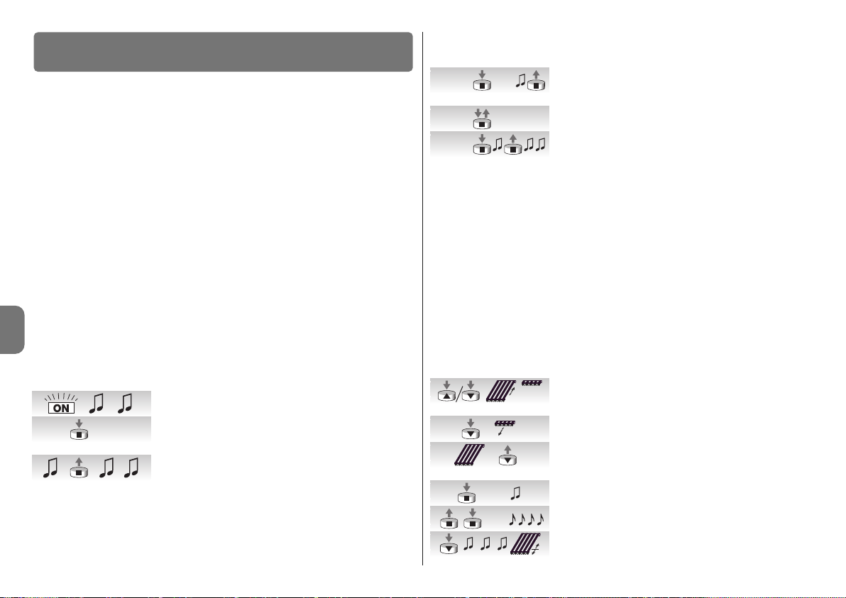
4 – Deutsch
DE
Die Programmierung ist in 3 Abschnitte unterteilt:
1. Speicherung der Sender
2. Programmierung der Positionen “0” und “1”
3. Programmierung von Zusatzfunktionen
Damit ein Sender einen Motor der Serie NEOMAT-T steuern kann, muss eine Speicherphase ausgeführt werden, wie in Tabelle A1 angegeben.
ACHTUNG:
• Alle Speichersequenzen sind auf Zeit bzw. müssen innerhalb der vorgesehenen
Zeitgrenzen ausgeführt werden.
• Bei Sendern, die mehrere “Gruppen” vorsehen, muss vor der Speicherung die Sender-
gruppe gewählt werden, welcher der Motor zugeordnet werden soll.
• Die Speicherung per Funk kann an allen Empfängern erfolgen, die sich innerhalb der
Reichweite des Senders befinden; daher nur den betreffenden Empfänger gespeist halten.
Es kann geprüft werden, ob bereits Sender im Motor gespeichert sind; hierzu genügt es, die
Anzahl an Bieptönen zu überprüfen, die beim Einschalten des Motors abgegeben werden:
- 2 lange Bieptöne = kein Sender gespeichert.
- 2 kurze Bieptöne = gespeicherte Sender vorhanden.
4.1 - Programmierung der Sender
––––––––––––––––––––––––––––––––––––––––––––––––––––––––––––––––––––––––––––
Tabelle “A1” - Speicherung des ersten Senders (in Modus I)
––––––––––––––––––––––––––––––––––––––––––––––––––––––––––––––––––––––––––––
01. Den Motor an der Netzstromversorgung anschließen;
gleich danach wird man 2 lange Bieptöne hören.
02. Innerhalb von 5 Sekunden auf Taste ■ des zu speichernden Senders drücken und gedrückt halten (ca. 3 Sekunden).
03. Ta s te ■ beim ersten der 3 Bieptöne loslassen, welche
die Speicherung bestätigen.
Siehe Tabelle A2 für die Speicherung weiterer Sender
Wenn ein oder mehrere Sender bereits gespeichert sind, können andere wie in Tabelle A2
angegeben gespeichert werden:
4
Programmierungen
––––––––––––––––––––––––––––––––––––––––––––––––––––––––––––––––––––––––––––
Tabelle “A2” - Speicherung weiterer Sender in Modus I
––––––––––––––––––––––––––––––––––––––––––––––––––––––––––––––––––––––––––––
01. Auf die Taste ■ des neuen Senders drücken und ge -
drückt halten (ca. 5 Sekunden), bis man einen Biepton
hört, dann Taste ■ loslassen.
02. 3-Mal langsam auf Taste ■ eines alten, bereits gespei-
cherten Senders drücken.
03. Erneut auf Taste ■ des neuen Senders drücken. Taste ■
beim ersten der 3 Bieptöne loslassen, welche die Speicherung bestätigen.
Anmerkung: falls der Speicher voll ist (14 Sender), werden 6 Bieptöne melden, dass der
Sender nicht gespeichert werden kann.
4.2 - Programmierung der Positionen “0” und “1”
Zur Programmierung der Positionen muss eine bereits in Modus I gespeicherte Fernbedienung verwendet werden. Solange die Positionen “0” und “1” nicht gültig in der Steuerung
gespeichert sind, wird die Bewegung nur erfolgen, solange der Steuerbefehl gegeben ist.
Anfänglich ist der Drehsinn des Motors nicht festgelegt, aber nach der Beendigung von
Punkt 1 in Tabelle “A3” wird der Motordrehsinn den Fernbedienungstasten automatisch
zugeteilt.
Zur Programmierung der Positionen 0 und 1 muss das in Tabelle „A3“ angegebene Verfahren durchgeführt werden:
––––––––––––––––––––––––––––––––––––––––––––––––––––––––––––––––––––––––––––
Tabelle “A3” - Programmierung der Positionen “0” und “1”
––––––––––––––––––––––––––––––––––––––––––––––––––––––––––––––––––––––––––––
01. Auf Taste ▲ oder ▼ einer gespeicherten Fernbedienung
drücken und gedrückt halten, bis das Schließen der
Markise beendet ist und der Motor automatisch anhält.
02. Auf Taste ▼ drücken und gedrückt halten: die Markise
geht nach unten.
03. Die Taste ▼ loslassen, wenn die Markise die gewünschte Position (“1”) erreicht hat. Falls nötig, die Position mit
den Tasten ▼ und ▲ justieren.
04. Die Taste ■ des Senders gedrückt halten, bis man einen
Biepton hört (nach ca. 5 Sekunden).
05. Loslassen und noch mal 5 Sekunden lang auf die Taste
■ drücken, bis man 4 Bieptöne kurz aufeinander hört.
06. Auf Taste ▼ drücken, bis 3 Bieptöne und eine kurze Aufund Abwärtsbewegung die Speicherung des Maßes
bestätigen werden.
3s...
5s...
x 3
neu
alt
neu
5s...
5s...

Deutsch – 5
DE
4.3 - Programmierung von Zusatzfunktionen
Zusatzfunktionen können erst programmiert werden, nachdem die Programmierung der
Positionen “0” und “1” beendet ist.
4.3.1 - Programmierung der Zwischenposition “I”
Nachdem eine Zwischenposition “I” programmiert ist, kann die Markise durch gleichzeitigen Druck auf die 2 Sendertasten ▲▼in die Position “I” bewegt werden.
Zur Speicherung der Zwischenposition muss das in Tabelle “A4” angegebene Verfahren
durchgeführt werden:
––––––––––––––––––––––––––––––––––––––––––––––––––––––––––––––––––––––––––––
Tabelle “A4” - Programmierung der Zwischenposition “I”
––––––––––––––––––––––––––––––––––––––––––––––––––––––––––––––––––––––––––––
01. Die Markise mit den Tasten ▲ ■ ▼ einer Fernbedienung
dorthin verschieben, wo die Position “I” sein soll.
02. Die Taste ■ des Senders gedrückt halten, bis man einen
Biepton hört (nach ca. 5 Sekunden).
03. Loslassen und noch mal 5 Sekunden lang auf die Taste
■ drücken, bis man 4 Bieptöne kurz aufeinander hört.
04. Gleichzeitig auf die Tasten ▼ ▲ drücken, bis die Spei-
cherung des Maßes durch 3 Bieptöne bestätigt wird.
4.3.2 - Deaktivierung oder erneute Aktivierung der Drehmomentreduzierung
während der Schließung (RDC)
Die Drehmomentreduzierung ist eine Funktion, die das Zugmoment kurz vor dem vollständigen Schließen der Markise gegen den Kasten um ca. 50% verringert, so dass ein zu starker Zug der Markisenstoffbahn vermieden wird. Diese Funktion wird automatisch nach der
Programmierung der Werte 0 und 1 aktiviert (die Programmierung erfolgt immer bei
Höchstkraftaufwand), kann aber auch deaktiviert (oder erneut aktiviert) werden.
Bemerkung - Die automatische Aktivierung der Funktion RDC erfolgt nicht, wenn die Programmierung der Positionen mit den Programmiergeräten TTP, TTI und O-ViewTT vorgenommen wird; in diesem Fall kann die Funktion auf Wunsch von Hand aktiviert werden.
––––––––––––––––––––––––––––––––––––––––––––––––––––––––––––––––––––––––––––
Tabelle “A5” - Deaktivierung oder erneute Aktivierung der Drehmomentreduzierung (RDC)
––––––––––––––––––––––––––––––––––––––––––––––––––––––––––––––––––––––––––––
01. Die Taste ■ eines bereits gespeicherten Senders ge -
drückt halten, bis man einen Biepton hört (nach ca. 5
Sekunden).
02. Loslassen und noch mal 5 Sekunden lang auf die Taste
■ drücken, bis man 4 Bieptöne kurz aufeinander hört.
03. Die Taste ■ drücken, bis die Hinweis-Pieptöne begin-
nen. 3 mal Piepen bedeutet aktive RDC (Schließen bei
re duziertem Drehmoment); 5 mal Piepen bedeutet nicht
aktive RDC (Schließen bei Höchstdrehmoment).
4.3.3 - Löschen der Positionen
Um die vorher gespeicherten Positionen ändern zu können, müssen sie zuerst gelöscht
werden; erst dann können die neuen Positionen programmiert werden.
––––––––––––––––––––––––––––––––––––––––––––––––––––––––––––––––––––––––––––
Tabelle “A6” - Löschen der Zwischenposition “I”
––––––––––––––––––––––––––––––––––––––––––––––––––––––––––––––––––––––––––––
01. Die Taste ■ eines bereits gespeicherten Senders
gedrückt halten, bis man einen Biepton hört (nach ca. 5
Sekunden).
02. Loslassen und noch mal 5 Sekunden lang auf die Taste
■ drücken, bis man 4 Bieptöne kurz aufeinander hört.
03. Gleichzeitig auf die Tasten ▼ ▲ drücken, bis das Lö schen
der Zwischenposition durch 5 Bieptöne bestätigt wird.
––––––––––––––––––––––––––––––––––––––––––––––––––––––––––––––––––––––––––––
Tabelle “A7” - Löschen der Positionen “0” und “1”
––––––––––––––––––––––––––––––––––––––––––––––––––––––––––––––––––––––––––––
01. Die Taste ■ eines bereits gespeicherten Senders gedrückt
halten, bis man einen Biepton hört (nach ca. 5 Sekunden).
02. Loslassen und noch mal 5 Sekunden lang auf die Taste
■ drücken, bis man 4 Bieptöne kurz aufeinander hört.
03. Auf Taste ▼ drücken, bis das Löschen der Positionen
“0” und “1” durch 5 Bieptöne bestätigt wird.
ACHTUNG: Nach dem Löschen der Positionen “0” und “1” wird sich die Markise nur im
Todmannbetrieb bewegen und neue Positionen müssen gespeichert werden.
Anmerkung: die eventuell programmierte Zwischenposition “I” und die RDC-Funktion werden mit diesem Vorgang nicht gelöscht. Wenn man alles löschen will (auch die Sendercodes), ist auf Tabelle “A14” Bezug zu nehmen.
4.3.4 - Programmierung der Ansprechstufe des Windwächters
Wenn am Eingang “Wetterwächter” ein Windwächter der Serie “VOLO” o “VOLO S2 angeschlossen wird, aktiviert sich der Schutz “Wind” bzw. das automatische Aufrollen der Markise, wenn der Wind die programmierte Stufe überschreitet. Falls die Stufe länger als 3
Sekunden überschritten wird, aktiviert sich ein Befehl wie mit Taste ▲ und jede andere
Bewegung wird blockiert, bis die Windstärke mindestens 1 Minute lang die programmierte
Stufe unterschreitet. Es besteht die Wahl zwischen 5 Stufen: 1=5Km/h, 2=10Km/h,
3=15Km/h, 4=30Km/h und 5=45Km/h. (die werkseitig eingestellte Stufe ist die Nr. 3).
5s...
5s...
5s...
5s...
5s...
5s...
5s...
5s...
(...)
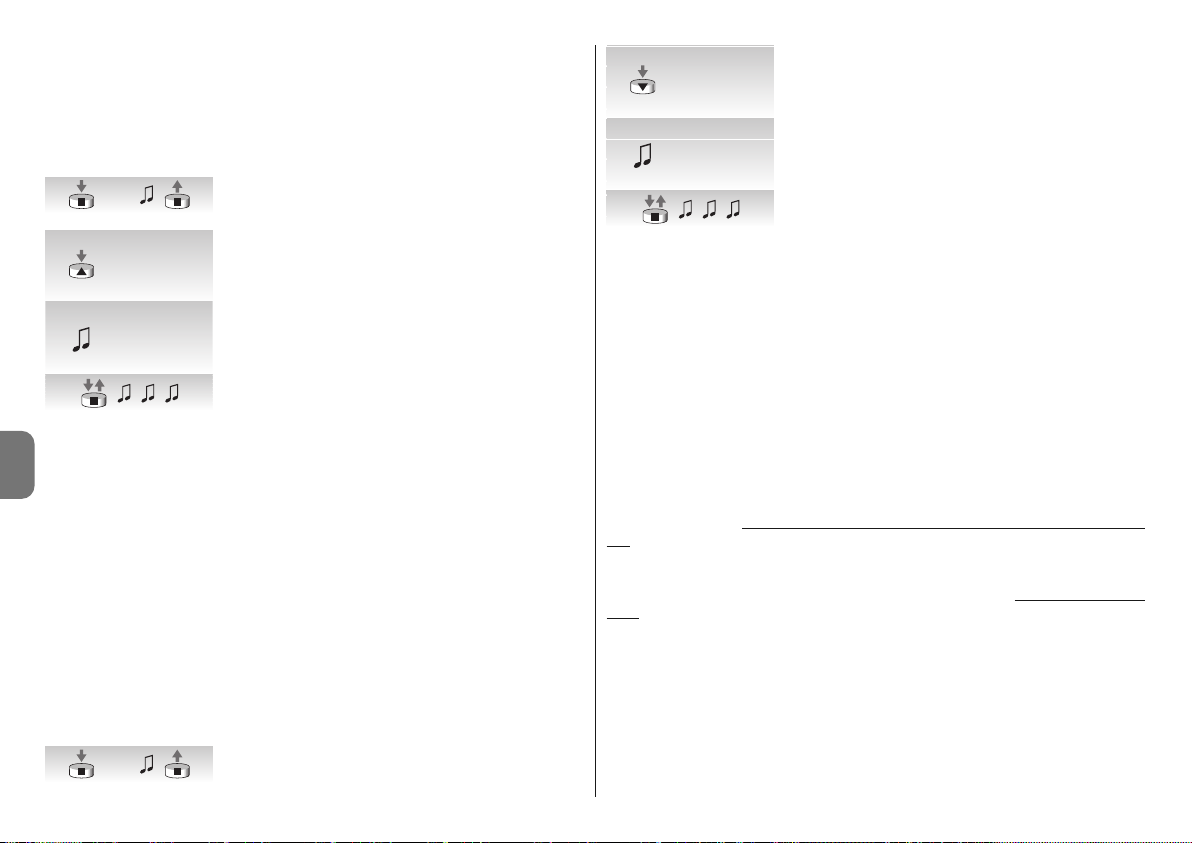
6 – Deutsch
DE
Falls der Wächter “VOLO ST” oder Funkwächter Volo S Radio und Nemo verwendet wird,
werden die Windeingriffsgrenzwerte direkt im Wächter programmiert (siehe diesbezügliche
Anleitungen).
Zur Änderung der programmierten Stufe:
––––––––––––––––––––––––––––––––––––––––––––––––––––––––––––––––––––––––––––
Tabelle “A9” - Änderung der Ansprechstufe des Schutzes “Wind”
––––––––––––––––––––––––––––––––––––––––––––––––––––––––––––––––––––––––––––
01. Die Taste ■ eines gespeicherten Senders gedrückt hal-
ten (ca. 5 Sekunden), bis man einen Biepton hört, dann
Ta st e ■ loslassen.
02. Langsam sooft auf Taste ▲ drücken, wie die gewünsch-
te Stufe ist (1, 2, 3, 4 oder 5).
03. Gleich danach wird man so viele Bieptöne hören, wie die
gewünschte Stufe ist.
04. Auf Taste ■ drücken und loslassen, um zu bestätigen.
Wenn man an Punkt 3 nicht so viele Bieptöne hört, wie die gewünschte Stufe ist, auf keine
Taste drücken und einige Sekunden warten, um ohne Änderung der Stufe zu beenden.
4.3.5 - Programmierung der Ansprechstufe des Wetterwächters “Sonne”
Wenn am Eingang “Wetterwächter” ein Sonnewächter der Serie “VOLO-S” angeschlossen
wird, aktiviert sich der Automatismus “Sonne” bzw. das automatische Abrollen der Markise,
wenn “Sonne” die programmierte Stufe überschreitet. Falls die Stufe länger als 2 Minuten
überschritten wird, aktiviert sich ein Befehl wie mit Taste ▼; wenn “Sonne” dann 15 Minuten
lang die programmierte Stufe unterschreitet, aktiviert sich ein Befehl wie mit Taste ▲.
Für den Automatismus “Sonne” besteht die Wahl zwischen 5 Stufen: 1=5Klux, 2=10Klux,
3=15Klux, 4=30Klux e 5=45Klux (werkseitig ist Stufe Nr. 3 eingestellt).
––––––––––––––––––––––––––––––––––––––––––––––––––––––––––––––––––––––––––––
Tabelle “A10” - Änderung der Ansprechstufe des Automatismus “Sonne”
––––––––––––––––––––––––––––––––––––––––––––––––––––––––––––––––––––––––––––
Falls der Wächter “VOLO ST” oder Funkwächter Volo S Radio und Nemo verwendet wird,
werden die Sonneneingriffsgrenzwerte direkt im Wächter programmiert (siehe diesbezügliche Anleitungen).
01. Die Taste ■ eines gespeicherten Senders gedrückt hal-
ten (ca. 5 Sekunden), bis man einen Biepton hört, dann
Ta st e ■ loslassen.
02. Langsam sooft auf Taste ▼ drücken, wie die gewünsch-
te Stufe ist (1, 2, 3, 4 oder 5).
03. Gleich danach wird man so viele Bieptöne hören, wie die
gewünschte Stufe ist.
04. Auf Taste ■ drücken und loslassen, um zu bestätigen.
Wenn man an Punkt 3 nicht so viele Bieptöne hört, wie die gewünschte Stufe ist, auf keine
Taste drücken und einige Sekunden warten, um ohne Änderung der Stufe zu beenden.
4.3.6 - Die Eingriffsrichtung bei Regen ändern
Wenn ein Regenwächter Nemo WSRT verwendet wird und der Sensor Regen erfasst, wird
den Motoren eine Informationen übertragen und eine Bewegung in der programmierten
Richtung ausgelöst (werkseitig wird die Richtung “Anheben” programmiert).
Um die Regeneingriffsrichtung zu ändern:
01. Taste ■ eines bereits gespeicherten Senders gedrückt halten, bis man einen Piepton
hört (nach ca. 5 Sekunden), dann die Taste freigeben.
02. Dieselbe Taste ■ weitere 3 Mal drücken.
03. Die Taste mit der gewünschten Richtung drücken (Anheben oder Senken); nun gibt
der Motor 3 Pieptöne ab = neu gespeicherte Richtung.
Den durch den Sonnenwächter hervorgerufenen automatischen Bewegungen können in jedem
Moment auch die durch den Nutzer übersendeten Steuerungen mithilfe eines normalen Senders zugefügt werden, diese herrschen gegenüber den Steuerungen des Sonnenwäch
-
ters mit den im folgenden Beispiel genannten Vorgehensweisen vor. Wenn die Markise in
Position “1” ist (automatisch durch die Überschreitung des Sonnengrenzwerts erreicht)
und nachdem der Nutzer das Anheben der Markise bis Position “0” steuert, erfasst das
System weiterhin die Überschreitung des Sonnengrenzwerts und bewegt die Markise
nicht (diese bleibt in der durch den Nutzer bestimmten Position).
Der durch die Handsteuerung unterbrochene “automatische Zyklus” wird wieder hergestellt,
wenn die Lichtstärke unter den Grenzwert sinkt (normalerweise bei Sonnenuntergang).
4.3.7 - Programmierung der Funktionen “FRT”
Nachdem die Positionen “0” und “1” programmiert sind, kann die Position “2” programmiert werden, die zur Aktivierung der Tuchspannungsfunktion FRT notwendig ist.
Zur Programmierung der Position “2” ist nach dem Verfahren in Tabelle “A11” vorzugehen.
5s...
5s...
x 1 = 5 Km/h
x 2 = 10 Km/h
x 3 = 15 Km/h
x 4 = 30 Km/h
x 5 = 45 Km/h
x 1 = 5 Km/h
x 2 = 10 Km/h
x 3 = 15 Km/h
x 4 = 30 Km/h
x 5 = 45 Km/h
x 1 = 5 Klux
x 2 = 10 Klux
x 3 = 15 Klux
x 4 = 30 Klux
x 5 = 45 Klux
x 1 = 5 Klux
x 2 = 10 Klux
x 3 = 15 Klux
x 4 = 30 Klux
x 5 = 45 Klux
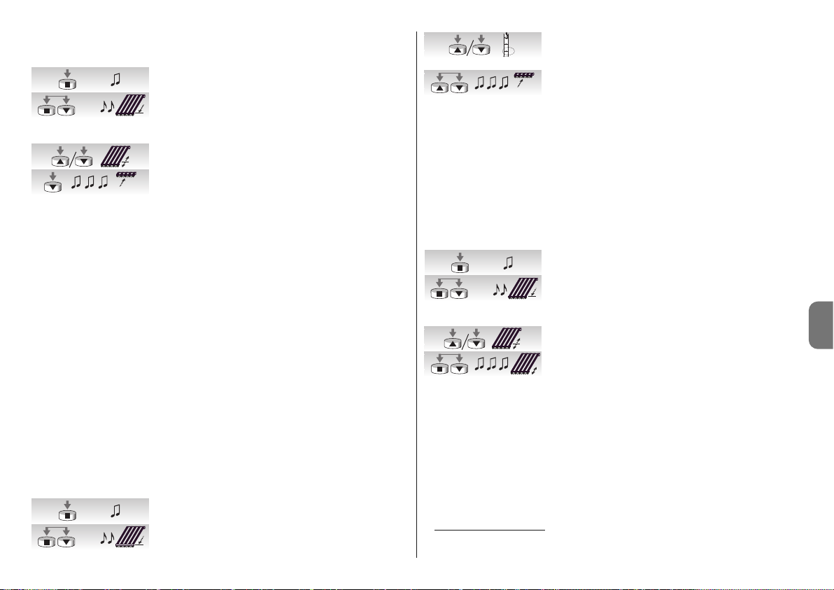
Deutsch – 7
DE
––––––––––––––––––––––––––––––––––––––––––––––––––––––––––––––––––––––––––––
Tabelle “A11” - Programmierung von Position “2”
––––––––––––––––––––––––––––––––––––––––––––––––––––––––––––––––––––––––––––
01. Ta s te ■ eines bereits gespeicherten Senders gedrückt
halten, bis man einen Biepton hört (nach ca. 5 Sekunden).
02. Die Tasten ■ und ▼ drücken und weitere 5 Sekunden
lang gedrückt halten, bis man 2 Bieptöne kurz aufeinander hört. Nun begibt sich die Markise automatisch in die
Endlaufposition unten (Position “1”).
03. Die Markise innerhalb von 5 Sekunden mit den Tasten ▼
und ▲ in die gewünschte Tuchspannungsposition.
04. Die Position innerhalb von 5 Sekunden durch Drücken
der Sendertaste ■ bestätigen, bis man drei Bieptöne
hört. Danach begibt sich die Markise in die programmierte Endlaufposition unten (Position “1”).
Anmerkung: wenn man die Programmierung nicht wie in Punkt 4 beschrieben bestätigt,
werden die Änderungen abgebrochen und die früheren Programmierungen bleiben.
Wenn man diese Funktion nach ihrer Programmierung löschen will, muss das Verfahren in
Tabelle A13 ohne Änderung der Position “1” (Schritt Nr. 3 auslassen) ausgeführt werden.
Wenn man die Position “2” programmiert, berechnet die elektronische Steuerung automatisch die Differenz zwischen Position “2” und Position “1”, so dass die Markise bei jedem
Abstiegsbefehl bis zur größeren der beiden Positionen nach unten geht, dann wird das
Markisentuch bis zur kleineren der beiden Positionen aufgerollt.
4.3.8 - Programmierung der Funktion “FTC”
Nachdem die Positionen “0” und “1” programmiert sind, kann die Position "S" programmiert werden, die zur Aktivierung der Funktion "FTC" für die Automatisierung von Markisen
mit einem automatischen Einspannmechanismus notwendig ist. Damit der Mechanismus
korrekt funktioniert, muss Position “1” so programmiert sein, dass sie sich ein paar Zentimeter nach dem Einspannpunkt befindet, so dass das Einspannen in Anstieg ab Punkt “1”
erfolgt; die Position “S” muss so programmiert sein, dass sie sich ein paar Zentimeter nach
dem Ausspannpunkt befindet, so dass der Anstieg ab Punkt “S2 frei erfolgen kann.
Zur Programmierung der Position “S” ist nach dem Verfahren in Tabelle “A12” vorzugehen.
––––––––––––––––––––––––––––––––––––––––––––––––––––––––––––––––––––––––––––
Tabelle “A12” - Programmierung der Ausspannposition “S”
––––––––––––––––––––––––––––––––––––––––––––––––––––––––––––––––––––––––––––
01. Ta s te ■ eines bereits gespeicherten Senders gedrückt
halten, bis man einen Biepton hört (nach ca. 5 Sekunden).
02. Die Tasten ■ und ▼ drücken und weitere 5 Sekunden lang
gedrückt halten, bis man 2 Bieptöne kurz aufeinander hört.
Nun begibt sich die Markise automatisch in Position “1”.
03. Die Markise innerhalb von 5 Sekunden mit den Tasten ▼
und ▲ in die Ausspannposition “S” (unter Position “1”)
bringen.
04. Die Position innerhalb von 5 Sekunden durch gleichzeitiges Drücken der Sendertasten ▼ und ▲ bestätigen, bis
man drei Bieptöne hört. Nun begibt sich die Markise
automatisch in Position “0”.
Anmerkung: wenn man die Programmierung nicht wie in Punkt 4 beschrieben bestätigt,
werden die Änderungen abgebrochen und die früheren Programmierungen bleiben.
Wenn man diese Funktion nach ihrer Programmierung löschen will, muss das Verfahren in
Tabelle A13 ohne Änderung der Position "1" (Schritt Nr. 3 auslassen) ausgeführt werden.
4.3.9 - Änderung der Position “1”
Um die Position “1” zu verschieben, ist nach dem Verfahren in Tabelle “A13” vorzugehen.
––––––––––––––––––––––––––––––––––––––––––––––––––––––––––––––––––––––––––––
Tabelle “A13” - Änderung der Position “1”
––––––––––––––––––––––––––––––––––––––––––––––––––––––––––––––––––––––––––––
01. Ta s te ■ eines bereits gespeicherten Senders gedrückt
halten, bis man einen Biepton hört (nach ca. 5 Sekunden).
02. Die Tasten ■ und ▼ drücken und weitere 5 Sekunden
lang gedrückt halten, bis man 2 Bieptöne kurz aufeinander hört. Nun begibt sich die Markise automatisch in
Position “1”.
03. Die Markise innerhalb von 5 Sekunden mit den Tasten ▼
und ▲ in die neue Position verschieben.
04. Die Position innerhalb von 5 Sekunden durch gleichzeitiges Drücken der Sendertasten ■ und ▼ bestätigen, bis
man drei Bieptöne hört und eine kurze Auf- und Abbewegung erfolgt.
Anmerkung: wenn man die Programmierung nicht wie in Punkt 4 beschrieben bestätigt,
werden die Änderungen abgebrochen und die früheren Programmierungen bleiben.
Durch die Änderung der Position "1" werden auch die Funktionen "FRT" und "FTC"
gelöscht.
4.4 - Löschen des Speichers
Sollte das Löschen der Sender und der Programmierungen notwendig sein, kann die in
Tabelle A13 angegebene Sequenz ausgeführt werden.
Das Löschen ist möglich
:
• mit einem nicht gespeicherten Sender, mit Beginn des Verfahrens ab Punkt A
• mit einem bereits gespeicherten Sender, mit Beginn des Verfahrens ab Punkt Nr. 1.
5s...
5s...
5s...
5s...
5s...
1
S
5s...

8 – Deutsch
DE
Tabelle “A15”
Gelöscht werden können:
• nur die gespeicherten Sender, mit Beendigung an Punkt 4
• alles (Sender, Stufe der Wetterwächter, TTBUS-Adresse...), mit Vervollständigung des
Verfahrens bis Punkt 6.
––––––––––––––––––––––––––––––––––––––––––––––––––––––––––––––––––––––––––––
Tabelle “A14” - Löschen des Speichers
––––––––––––––––––––––––––––––––––––––––––––––––––––––––––––––––––––––––––––
A. Den Eingang Schrittbetrieb mit nicht gespeistem Motor
aktivieren (den weißen Draht am schwarz-weißen Draht
anschließen) und bis zum Ende des Verfahrens aktiviert
halten.
B. Den Motor an der Netzstromversorgung anschließen
und warten, bis man die anfänglichen Bieptöne hört.
01. Auf die Taste ■ eines Senders drücken und gedrückt
halten (ca. 5 Sekunden), bis man einen Biepton hört,
dann Taste 4 loslassen.
02. Die Taste ▲ des Senders gedrückt halten, bis man drei
Bieptöne hört; die Taste ▲ genau während dem dritten
Biepton loslassen.
03. Die Taste ■ des Senders gedrückt halten, bis man drei
Bieptöne hört; die Taste ■ genau während dem dritten
Biepton loslassen.
04. Die Taste ▼ des Senders gedrückt halten, bis man drei
Bieptöne hört; die Taste ▼ genau während dem dritten
Biepton loslassen.
05. Um alles zu löschen, innerhalb von 2 Sekunden auf beide Tasten ▲ und ▼ drücken.
06. Die Tasten ▲ und ▼ beim ersten der 5 Bieptöne loslas-
sen, die das Löschen bestätigen.
Die Motoren der Serie NEOMAT-T erkennen die Funksender der Serien ERGO, PLANO,
NICEWAY, VOLO S RADIO und NEMO (siehe das Kapitel 5.1“Verwendbare Sender”).
Weiterhin kann jeder Sendertaste über spezielle Speicherverfahren der Sender ein besonderer Befehl zugeordnet werden (siehe Kapitel 5.2 “Programmierung der Sender im Modus
I und Modus II”).
Achtung: zum Programmieren nur Sender verwenden, die in Modus I gespeichert sind.
5
Weitere Auskünfte
5.1 - Verwendbare Sender
In Tabelle A15 sind die Sender angegeben, die mit der entsprechenden Codierung benutzt
werden können.
––––––––––––––––––––––––––––––––––––––––––––––––––––––––––––––––––––––––––––
Tabelle “A15” - Sender
• ERGO1 - ERGO4 - ERGO6 • PLANO1 - PLANO4 - PLANO6 - PLANO TIME • VOLO S
RADIO • NEMO • NICEWAY (die gesamte Linie) • FLO1R - FLO2R - FLO4R • VERY VR •
––––––––––––––––––––––––––––––––––––––––––––––––––––––––––––––––––––––––––––
5.2 - Speicherung der Sender in Modus I und Modus II
In den Tabellen “A1” und “A2” ist die Speicherung der Sender im “Modus I” beschrieben; in
diesem Modus ist jeder Taste ein präziser Steuerbefehl zugeteilt: Taste ▲ (1) = “Anstieg”;
Ta st e ■ (2) = “Stopp”; Taste ▼ (3) = “Abstieg”.
Die Sender können auch im "Modus II“ gespeichert werden; dieser Modus ermöglicht
größte Flexibilität bei der Benutzung der Sendertasten. An demselben Motor NEOMAT-T
können Sender sowohl im Modus I als auch im Modus II gespeichert werden.
5.2.1 - Modus I
Im Modus I ist der den Sendertasten zugeordnete Steuerbefehl fest: mit Taste ▲ (1) wird
der Befehl für “Anstieg” erteilt, mit Taste ■ (2) der Befehl für “Stopp” und mit Taste ▼ (3)
der Befehl für “Abstieg”; die eventuelle Taste 4 gibt den Befehl für “Stopp”.
P. P.
5s...

Deutsch – 9
DE
Im Modus I führt man nur eine Speicherphase aus und es wird nur ein Speicherplatz
belegt. Bei der Speicherung im Modus I ist es nicht wichtig, auf welche Taste gedrückt
wird. Siehe die Tabellen A1 und A2 für die Speicherung oder das Löschen der Sender in
Modus I.
Taste Steuerbefehl
Ta st e ▲ oder 1 Anstieg
Ta st e ■ oder 2 Stopp
Ta st e ▼ oder 3 Abstieg
Taste 4 Stopp
5.2.2 - Modus II
Im Modus II kann jeder Sendertaste einer der 4 folgenden Steuerbefehle zugeteilt werden:
1 = Schrittbetrieb; 2 = Anstieg-Stopp; 3 = Abstieg-Stopp; 4 = Stopp.
Im Modus II führt man für jede Taste eine Speicherphase aus und jede Taste belegt einen
Speicherplatz. Bei der Speicherung im Modus II wird die gedrückte Taste gespeichert.
Wenn man einer anderen Taste desselben Senders einen anderen Steuerbefehl zuteilen
will, muss eine neue Speicherung durchgeführt werden.
Nr. Steuerbefehl
1 Schrittbetrieb (Anstieg-Stopp-Abstieg-Stopp…),
2 Anstieg-Stopp (Anstieg-Stopp-Anstieg-Stopp…)
3 Abstieg-Stopp (Abstieg-Stopp-Abstieg-Stopp…)
4 Stopp
5.2.3 - Beispiel für eine gemischte Speicherung in Modus I und II
Über entsprechende Speicherung in Modus I und Modus II können auch Gruppenbefehle
erstellt werden, wie im Beispiel in der Abb. F.
• Der in Modus I an A1 und A2 gespeicherte Sender T1 (Ergo1) gibt den Befehl für
Anstieg, Stopp und Abstieg gleichzeitig sowohl an A1 als auch an A2.
• Der im Modus I nur an A3 gespeicherte Sender T2 (Plano1) gibt den Befehl für Anstieg,
Stopp und Abstieg nur an A3.
• Der im Modus I nur an A4 gespeicherte Sender T3 (Planotime) gibt den Befehl für
Anstieg, Stopp und Abstieg nur an A4.
• Der im Modus II (Schrittbetrieb) gespeicherte Sender T4 (WM001C) steuert nur A4.
• Der Sender T5 (WM003G), im Modus I gespeichert, um mit Gruppe 1 an A1 und A2 zu
steuern und mit Gruppe 2, um an A3 zu steuern, gibt den Befehl für Anstieg, Stopp und
Abstieg an A1 und A2, A3 oder A4.
• Der Sender T6 (Flo4R), im Modus II an A4 (Tasten 1 und 3), an A5 (Taste 2) und A6 (Taste 4) gespeichert, gibt den Befehl für An- und Abstieg von A4 oder für die Öffnung des
Garagentors A5 oder des automatischen Tors A6.
ACHTUNG:
• Mit einem in Modus II gespeicherten Sender können keine Funktionen programmiert
werden (Positionen, Stufen....), da bei dieser Sequenz der Druck auf verschiedene Tas-
ten wie zum Beispiel auf Taste ■ und Taste ▲ erforderlich ist.
• Mit einem in Modus II gespeicherten Sender können keine Steuerbefehle für "Vielfach-
gruppen“ erteilt werden.
Wenn ein oder mehrere Sender bereits gespeichert sind, können andere wie in Tabelle A16
angegeben gespeichert werden:
––––––––––––––––––––––––––––––––––––––––––––––––––––––––––––––––––––––––––––
Tabelle “A16” - Speicherung weiterer Sender in Modus II
––––––––––––––––––––––––––––––––––––––––––––––––––––––––––––––––––––––––––––
01. Auf die zu speichernde Taste des neuen Senders drü-
cken und gedrückt halten (ca. 5 Sekunden), bis man
einen Biepton hört, dann die Taste loslassen.
02. Innerhalb von 5 Sekunden auf die Taste eines alten,
bereits gespeicherten Senders drücken und gedrückt
halten (ca. 5 Sekunden), bis man zwei Bieptöne, dann
die Taste loslassen.
03. Innerhalb von 5 Sekunden sooft auf dieselbe Taste am
alten Sender drücken, wie die Zahl des gewünschten
Steuerbefehls ist: 1 = Schrittbetrieb; 2 = Anstieg; 3 =
Abstieg; 4 = Stopp.
04. Nach ca. 3 Sekunden wird man so viele Bieptöne hören,
wie die Zahl des gewählten Steuerbefehls ist.
05. Innerhalb von 2 Sekunden auf dieselbe Taste des neuen
Senders drücken.
06. Die Taste beim ersten der 3 Bieptöne loslassen, welche
die Speicherung bestätigen.
Wenn man an Punkt 5 nicht so viele Bieptöne hört, wie die Zahl des gewünschten Befehls
ist, auf keine Taste drücken und einige Sekunden warten, um die Programmierung ohne
Speicherung zu beenden.
Anmerkung: Falls der Speicher voll ist (14 Sender), werden 6 Bieptöne melden, dass der
Sender nicht gespeichert werden kann.
Ein neuer Sender kann mit den Merkmalen des alten Senders nach dem Verfahren in
Tabelle A17 auf einfache Weise gespeichert werden. Der so gespeicherte neue Sender
wird die Merkmale des alten erben, d.h. dass der neue Sender im Modus I funktionieren
wird, wenn der alte in diesem Modus gespeichert war; wenn der alte Sender im Modus II
gespeichert war, wird auch der Taste des neuen Senders derselbe Steuerbefehl wie am
alten Sender zugeteilt.
5s.
neu
5s.
alt
1- 4
neu
1- 43s.
neu

10 – Deutsch
DE
––––––––––––––––––––––––––––––––––––––––––––––––––––––––––––––––––––––––––––
Tabelle “A17” - Speicherung weiterer Sender
––––––––––––––––––––––––––––––––––––––––––––––––––––––––––––––––––––––––––––
01. Mindestens 3 Sekunden auf die zu speichernde Taste
des neuen Senders drücken und gedrückt halten, dann
die Taste loslassen.
02. Mindestens 3 Sekunden auf die bereits gespeicherte
Taste des alten Senders drücken und gedrückt halten,
dann die Taste loslassen.
03. Mindestens 3 Sekunden auf die zu speichernde Taste
des neuen Senders drücken
und gedrückt halten, dann die Taste loslassen.
04. Mindestens 3 Sekunden auf die bereits gespeicherte
Taste des alten Senders drücken und gedrückt halten,
dann die Taste loslassen.
05. Als Bestätigung der Speicherung des neuen Senders
wird man 3 Bieptöne hören.
Anmerkung: falls der Speicher voll ist (14 Sender), werden 6 Bieptöne melden, dass der
Sender nicht gespeichert werden kann.
Das vorliegende Produkt ist Teil der Automatisierung und muss daher zusammen
mit derselben entsorgt werden.
Wie die Installationsarbeiten muss auch die Abrüstung am Ende der Lebensdauer dieses
Produktes von Fachpersonal ausgeführt werden.
Dieses Produkt besteht aus verschiedenen Stoffen, von denen einige recycled werden
können, andere müssen hingegen entsorgt werden. Informieren Sie sich über die Recycling- oder Entsorgungssysteme für dieses Produkt, die von den auf Ihrem Gebiet gültigen
Verordnungen vorgesehen sind.
Achtung! – bestimmte Teile des Produktes können Schadstoffe oder gefährliche Substanzen enthalten, die, falls in die Umwelt gegeben, schädliche Wirkungen auf die Umwelt und
die menschliche Gesundheit haben könnten.
Wie durch das Symbol seitlich angegeben, ist es verboten, dieses Produkt
zum Haushaltmüll zu geben. Daher differenziert nach den Methoden entsorgen, die von den auf Ihrem Gebiet gültigen Verordnungen vorgesehen sind,
oder das Produkt dem Verkäufer beim Kauf eines neuen, gleichwertigen Produktes zurückgeben.
Achtung! – die örtlichen Verordnungen können schwere Strafen im Fall einer widerrechtlichen Entsorgung dieses Produktes vorsehen.
❏ Nachdem der Motor gespeist ist, wird kein Biepton abgeben und der Eingang Schrittbetrieb verursacht keine Bewegung.
Prüfen, ob der Motor mit der vorgesehenen Netzspannung gespeist ist; falls die Versorgung korrekt ist, liegt wahrscheinlich ein schwerer Defekt des Motors vor und der Motor
muss vom Kundendienst repariert werden.
❏ Nach einem Steuerbefehl bewegt sich der Motor nicht.
• Wenn er bis vor kurzem funktionierte, könnte der Wärmeschutz ausgelöst haben. Ein
paar Minuten warten, bis sich der Motor abkühlt.
• Prüfen, ob der Eingang “Schrittbetrieb” funktioniert, indem die Leiter weiß und schwarzweiß kurz miteinander vereint werden.
• Prüfen, dass mindestens ein Sender gespeichert ist und kontrollieren, dass der Motor
beim Einschalten kurze Bieptöne abgibt.
• Prüfen, ob Sender und Motor in Verbindung stehen, indem mindestens 5 Sekunden auf
Ta st e ■ (2) eines Senders (gespeichert oder nicht) gedrückt wird; wenn man einen Biepton hört, empfängt der Motor das Sendersignal und man kann daher auf die letzte Überprüfung übergehen; andernfalls die nächste Überprüfung ausführen.
7
Was tun, wenn... kurzer Leitfaden, wenn etwas nicht funktioniert!
6
Entsorgung des Produktes
>3s.
neu
>3s.
alt
>3s.
neu
>3s.
alt

Deutsch – 11
DE
Technische Merkmale der Rohrmotoren NEOMAT-MT und NEOMAT-LT
• Versorgungsspannung und Frequenz: siehe technische Daten auf dem Etikett eines
jeden Modells
• Stromaufnahme und Leistung: siehe technische Daten auf dem Etikett eines jeden
Modells
• Drehmoment und Geschwindigkeit: siehe technische Daten auf dem Etikett eines
jeden Modells
• Motordurchmesser: NEOMAT-MT = 45 mm; NEOMAT-LT = 58 mm
• Präzision (Auflösung) des elektronischen Endschalters: größer als 0,55° (hängt von
der NEOMAT-TT Version ab)
• Präzision der Endschalterpositionen: Klasse 2 (± 5%)
• Mechanische Beständigkeit: gemäß EN 14202
• Dauerbetriebszeit: max. 4 Minuten
• Schutzart: IP 44
• Betriebstemperatur: -20 ÷ +55 °C
• Länge des Anschlusskabels: 3 m
• Spannung der Signale (Schrittbetrieb, TTBUS…): ca. 24 V
• Stufen des Windwächters: 5 gleich ca. 5, 10, 15, 30 oder 45 Km/h (mit den Wind-
wächtern VOLO oder VOLOS)
• Stufen des Sonnewächters: 5 gleich ca. 5, 10, 15, 30 oder 45 Km/h (mit VOLOS )
• Länge der Signalkabel (Schrittbetrieb, TTBUS…): max. 30 m, falls in der Nähe ande-
rer Kabel, andernfalls 100 m
• Frequenz des Funkempfängers: 433.92 MHz
• Codierung des Funkempfängers: Rolling Code 52 Bit, FLOR und FLOR+INFO
• Anzahl an speicherbaren Sendern: 14, inklusive max. 3 Wetterwächter VOLO-S-
Radio
• Reichweite der Sender: ca. 150 m auf freiem Feld und 20 m in Gebäuden (*)
Anmerkungen:
– (*) Die Reichweite der Sender kann von anderen Vorrichtungen beeinträchtigt werden,
die mit derselben Frequenz in der Nähe in Betrieb sind (zum Beispiel Kopfhörer, Alarmsysteme usw.), wodurch Störungen mit dem Empfänger hervorgerufen werden. Im Falle
starker Störungen kann Nice keine Garantie über die reelle Reichweite ihrer Funkgeräte
bieten.
– Alle angegebenen technischen Merkmale beziehen sich auf eine Temperatur von 20°C
(±5°C).
– Nice S.p.a. behält sich das Recht vor, jederzeit als nötig betrachtete Änderungen am
Produkt vorzunehmen, wobei Funktionalitäten und Einsatzzweck beibehalten werden.
• Mit diesem erfahrungsgemäßen Test prüfen, ob der Sender das Funksignal korrekt
abgibt: auf eine Taste drücken und die LED der Antenne eines handelsüblichen Funkgeräts (besser nicht teuer) nähern, das eingeschaltet und auf FM Frequenz 108,5 MHz
gestellt sein muss: man müsste ein leichtes, pulsierendes und krächzendes Geräusch
hören.
• Langsam und einzeln auf alle Sendertasten drücken und prüfen, dass keine Sendertaste
eine Motorbewegung verursacht. Das bedeutet, dass jener Sender nicht gespeichert ist.
❏ Nach einem Funkbefehl hört man 6 Bieptöne, aber es erfolgt keine Bewegung.
Die Funksteuerung ist nicht synchronisiert: die Speicherung des Senders muss wiederholt
werden.
❏ Nach einem Befehl hört man 10 Bieptöne, dann startet die Bewegung.
Die Selbstdiagnose der gespeicherten Parameter hat einen Fehler wahrgenommen (Positionen, TTBUS-Adresse, Windstufe sind falsch); die Programmierungen wiederholen.
❏ Beim Abstieg, bevor die vorgesehene Position (Pos.“0”, Pos.“I”) erreicht
wird, hält der Motor an und versucht dann 3 Mal, wieder zu starten.
Kann normal sein: wenn beim Anstieg ein zu großer Kraftaufwand bemerkt wird, wird der
Motor ca. 1 Sekunde lang abgeschaltet, dann wird versucht, die Bewegung zu beenden;
prüfen, ob die Bewegung durch etwas behindert ist.
❏ Beim Abstieg, bevor die vorgesehene Position (Pos.“1”, Pos “I”) erreicht
wird, hält der Motor an.
Kann normal sein: wenn beim Abstieg ein zu großer Kraftaufwand bemerkt wird, wird der
Motor abgeschaltet; prüfen, ob die Bewegung durch etwas behindert ist.
❏ Der Motor bewegt sich nur infolge eines Steuerbefehls.
Falls die Positionen “0” und “1” nicht gespeichert sind, kann die Motorbewegung in Anund Abstieg nur mit der Todmannfunktion erfolgen (infolge eines Steuerbefehls). Die Positionen “0” und “1” programmieren.
❏ Der Motor bewegt sich während des Anhebens korrekt, aber während des
Senkens im Todmannbetrieb.
Die Selbstdiagnose der gespeicherten Parameter hat eine Störung in der Position des Mo tors festgestellt. Die Markise steuern, bis der ganze Anstiegsvorgang abgeschlossen ist.

12 – Deutsch
DE
EG-KONFORMITÄTSERKLÄRUNG
Anmerkung - Der Inhalt dieser Erklärung entspricht dem in der vor dem Druck dieser Anleitung verfügbaren, letzten
Revision, der offiziellen Unterlage, die sich im Firmensitz der Nice S.p.a. befindet. Dieser Text wurde aus Herausgebergründen überarbeitet.
Nummer: 223/Neomat T Revision: 3
Der Unterzeichnende Luigi Paro erklärt als Geschäftsführer unter seiner eigenen Verantwortung, dass das Produkt:
Herstellername: NICE s.p.a.
Adresse: Via Pezza Alta, 13, Z.I. Rustignè, 31046 - Oderzo (TV) Italien
Ty p: Rohrmotor für Kastenmarkisen mit eingebauter Steuerung und Funkempfänger
Modelle: Neomat MT, Neomat LT
Zubehör: Funksteuerungen der Serie Ergo, NiceWay, VOLO-S-Radio Windwächter VOLO, VOLO-S
den Vorschriften der folgenden europäischen Richtlinie entspricht:
• 1999/5/EG RICHTLINIE 1999/5/EG DES EUROPAPARLAMENTS UND DES RATES vom 9. März 1999, was Funk-
geräte und Terminals für das Fernmeldewesen und die gegenseitige Anerkennung ihrer Konformität gemäß folgender harmonisierter Normen betrifft:
- Schutz der Gesundheit: EN 50371:2002
- elektromagnetische Verträglichkeit: EN 301 489-1 V1.8.1:2008; EN 301 489-3 V1.4.1:2002
- elektrische Sicherheit: EN 60950-1:2006
- Funkspektrum: EN 300 220-2 V2.1.2:2007
Außerdem entspricht es den Vorschriften der folgenden europäischen Richtlinien, wie von der Richtlinie 93/68/EWG
des Rats vom 22. Juli 1993 vorgesehen:
• 2006/95/EG RICHTLINIE 2006/95/EG DES EUROPÄISCHEN PARLAMENTS UND DES RATS vom 12. Dezember
2006 bezüglich der Annäherung der Gesetze der Mitgliedsstaaten hinsichtlich elektrischen Materials, das innerhalb
bestimmter Spannungslimits verwendet wird und zwar gemäß den folgenden übereinstimmenden Normen: EN
60335-1:2002 + A1:2004 + A11:2004 + A12:2006 + A2:2006 + A13:2008; EN 60335-2-97:2006 + A11:2008;
EN50366:2003 + A1:2006
• 2004/108/EG RICHTLINIE 2004/108/EG DES EUROPÄISCHEN PARLAMENTS UND RATS vom 15. Dezember
2004 bezüglich der Annäherung der Gesetzgebungen der Mitgliedsstaaten, was die elektromagnetische Verträglichkeit betrifft und die Richtlinie 89/336/EWG aufhebt und zwar gemäß den folgenden Normen: EN 55014-1:2006;
EN 55014-2:1997 + A1:2001; EN 61000-3-2:2006; EN 61000-3-3:2007
Oderzo, 28. Juli 2009
Luigi Paro
(Geschäftsführer)

Polski – 1
PL
POLSKI
instrukcje oryginalne
UWAGA! - Niniejsza instrukcja zawiera ważne zalece-
nia dla bezpieczeństwa związane z INSTALOWANIEM i UŻYTKOWANIEM produktu; instrukcje należy
przechowywać do przyszłej konsultacji.
UWAGA! - Niewłaściwa instalacja może skutkować
ciężkimi obrażeniami. Z tego też powodu podczas
pracy należy przestrzegać wszystkie instrukcje in sta lowania znajdujące się w niniejszej instrukcji.
UWAGA! - Mając na uwadze bezpieczeństwo pracow-
ników należy przestrzegać niniejsze instrukcje.
• Silniki z serii NEOMAT-T, w wersjach NEOMAT-MT Ø45mm
i NEOMAT-LT Ø58mm są przeznaczone do zautomatyzowania markiz wyposażonych w skrzynkę nadokienną;
każde inne ich zastosowanie jest nieprawidłowe i
zabronione!
• Siłowniki zaprojektowane są do użytku w zespołach
mieszkaniowych; czas pracy ciągłej przewidziany jest na
4 minuty.
• Przy wyborze typu silnika, w zależności od jego zastosowania, należy mieć na uwadze moment nominalny i czas
funkcjonowania wskazany na tabliczce znamionowej.
• Minimalna średnica rury w jakiej może być zamontowany
silnik wynosi 52 mm dla NEOMAT-MT z momentem do
35Nm, 60 mm dla NEOMAT-MT z momentem wyższym
od 35Nm i 70 mm dla NEOMAT- LT.
• Instalacja musi być wykonana przez personel techniczny
z zgodnie z normami bezpieczeństwa.
• Przed przystąpieniem do instalowania należy odsunąć
wszystkie niepotrzebne przewody elektryczne, a wszystkie mechanizmy zbędne dla funkcjonowania napędu
powinny zostać unieruchomione.
• Części ruchome siłownika powinny być osłonięte, jeśli
jest on zamontowany na wysokości mniejszej niż 2,5 m.
Środki ostrożności i uwagi w zakresie
bezpieczeństwa
• W przypadku markiz odległość w poziomie od maksymalnego punktu otwarcia markizy do jakiegokolwiek
przedmiotu stałego nie może być mniejsza od 0,4 m.
• Przewód PCV znajdujący się na wyposażeniu siłowników serii NEOMAT-T sprawia, że są one odpowiednie do
instalowania we wnętrzach; do użytku zewnętrznego na leży osłonić cały przewód przy pomocy pancerza izolacyjnego, lub zamówić odpowiedni przewód typu S05
RN-F.
• Chronić siłownik przed zgnieceniem, uderzeniem, spadnięciem lub kontaktem z płynami jakiegokolwiek rodzaju;
nie dziurawić i nie wkręcać śrub na całej długości rury;
patrz rys. 1.
• Przycisk sterujący powinien być widoczny podczas użytkowania, ale powinny być odległy od części ruchomych i
znajdować się na wysokości przynajmniej 1,5 m.
• Nie wykonywać żadnych zmian i modyfikacji, jeśli nie są
one przewidziane w niniejszej instrukcji; operacje tego
rodzaju mogą jedynie spowodować niewłaściwe działanie; NICE nie bierze odpowiedzialności za szkody spowodowane przez zmodyfikowany produkt.
• W celu konserwacji oraz naprawy prosimy o zwrócenie
się do kompetentnego personelu technicznego.
• Powstrzymać od zbliżania się do rolety ludzi, kiedy jest w
ruchu.
• Nie uruchamiać rolety, jeśli w pobliżu są wykonywane
prace, na przykład: mycie szyb; w przypadku napędu
automatycznego należy także odłączyć zasilane elektryczne.
• Nie pozwalać dzieciom bawić się sterownikami i trzymać
nadajniki poza ich zasięgiem.
• Jeśli występują; często sprawdzać sprężyny wyważające lub stopień zużycia linek.
UWAGA! - Czujniki klimatyczne z serii Volo i Nemo nie
mogą być uwzględniane jako urządzenia zabezpiecza jące, które zapobiegają uszkodzeniu markizy w wyniku
padającego deszczu lub silnego wiatru (w rzeczywistości
zwykła awaria zasilania elektrycznego uniemożliwiłaby
automatyczne zwinięcie markizy). Czujniki klimatyczne
są uwzględniane jako część automatyki, użyteczna dla
zabezpieczenia markizy oraz dla zapewnienia komfortu
podczas jej używania.
Firma Nice zrzeka się wszelkiej odpowiedzialności za
szkody materialne, poniesione w wyniku wystąpienia zjawisk atmosferycznych niestwierdzonych przez czujniki
urządzenia.
UWAGA! - W przypadku deszczu i gdy spad markizy jest
mniejszy od 25% lub innej wartości wskazanej przez
producenta należy ją nawinąć, aby zapobiec tworzenia
się zbieraniu się wody w zagłębieniach materiału.
UWAGA! - W przypadku mrozu: poruszając markizą moż-
na uszkodzić mechanizm.
UWAGA! - W niektórych fazach programowania są wyko-
rzystywane ograniczniki mechaniczne rolety do zablokowania ruchu silnika; dlatego należy wybrać silnik z mo mentem obrotowym najbardziej odpowiednim dla parametrów rolety, uwzględniając rzeczywiste ob cią żenie i
unikając silników o zbyt dużej mocy.
Siłowniki serii NEOMAT-T w wersjach NEOMAT-MT o śr. 45
mm oraz NEOMAT-LT o śr. 58 mm są siłownikami elektrycznymi wyposażonymi w ogranicznik obrotów i po jednej stronie zakończone są odpowiednim wałkiem, na którym można zamocować koła napędowe (patrz rys. 2).
Instalacja silnika następuje poprzez włożenie go do rury
markizy; jest on w stanie wprawiać w ruch roletę podczas
podnoszenia i opuszczania.
Wbudowana w siłowniku centrala posiada elektroniczny
system wyłącznika krańcowego o dużej precyzji, który w
sposób ciągły odczytuje pozycję markizy.
W fazie programowania wpisuje się położenia graniczne:
zasłony zamkniętej i zasłony otwartej (i ewentualne pozycje
pośrednie); ruch zatrzyma się automatycznie po dojściu do
tych dwóch pozycji. Elektroniczny wyłącznik krańcowy jest
w stanie skompensować ewentualne wydłużenia płótna
(funkcja “CAT”) gwarantując perfekcyjne zamykanie skrzyni
i zapobiegając rozluźnieniu się płótna, kiedy jest otwarta.
Aby zapobiec nadmiernemu naciąganiu płótna w przypadku, kiedy markiza jest całkowicie zamknięta, silniki z serii
NEOMAT-T dysponują funkcją redukcji momentu obrotowego (funkcja “RDC”), która redukuje do około 50% mo ment obrotowy silnika krótko przed zamknięciem markizy.
Ta funkcja może być dezaktywowana z pomocą nadajnika
(patrz 4.3.2.) lub specjalnych urządzeń do programowania
TTP i OTT-View, które umożliwiają również wybór redukcji
na 3 poziomach: przy około 50, 40 lub 30% mo mentu
obro towego.
1
Opis produktu

2 – Polski
PL
Funkcje CAT i RDC zostały opracowane do symulacji za chowania osoby, która ręcznie, ostrożnie i starannie odwija
i zawija markizę.
Siłowniki serii NEOMAT posiadają kartę elektroniczną z
odbiornikiem radiowym pracującym na częstotliwości 433.92
MHz z technologią rolling code, w celu zagwarantowania
wysokiego poziom bezpieczeństwa. W każdym siłowniku
możliwe jest wczytanie do 14 nadajników serii ERGO, PLANO oraz NICEWAY; patrz rys. 3, co umożliwia sterowanie
siłownikiem na odległość, lub do 3 radiowych czujników wiatru i słońca “VOLO S RADIO” lub “NEMO”, które automatycznie sterują siłownikiem w zależności od sytuacji pogodowej.
Programowanie pozycji krańcowych i niektórych funkcji
dodatkowych możliwe jest bezpośrednio z nadajników, a
sygnał akustyczny “Bip” kierował będzie każdą fazą. Do stępne jest wejście do sterowania siłownikami także przyciskiem zewnętrznym (z funkcją Krok po kroku) lub za pomocą
linii “TTBUS”. Alternatywnie wobec przycisku Krok po kroku
w TTBUS możliwe jest podłączenie specjalnej fotokomórki
F210S, która wykrywa obecność ewentualnych przeszkód
uniemożliwiając wykonanie manewru opadania. Szczegóły
znajdują się w instrukcjach fotokomórki F210S.
Do wejścia czujników klimatycznych można podłączyć
opcjonalne czujniki wiatru, słońca i deszczu, które automatycznie włączają siłownik, kiedy sytuacja pogodowa będzie
tego wymagała.
W siłownikach NEOMAT-T można zaprogramować pewne
funkcje, które rozwiązuję specyficzne problemy (rys. A):
– FRT: funkcja ta służy do nawijania płótna w ilości zaprogramowanej po jej całkowitym odwinięciu. Służy do usunięcia nieestetycznych zwolnień płótna, kiedy markiza jest
otwarta. Dodatkowe informacje znajdują się w tabeli A10.
– FTC: służy do napędu markiz, których naciąg utrzymywany jest specjalnym mechanizmem automatycznego
zaczepu, jak na przykład w przypadku markizy w formie
daszku. Dodatkowe informacje znajdują się w tabeli A11.
UWAGA! - Niewłaściwa instalacja może skutkować
ciężkimi obrażeniami.
Przygotować siłownik według następującej sekwencji
czynności (patrz rys. 4 - 5 - 6):
2
Instalowanie
01. Wsunąć koronę wyłącznika krańcowego (E) na siłow-
nik (A) do momentu założenia jej na odpowiednią tulejkę zderzaka (F) dopasowując dwa wycięcia; docisnąć
aż do zetknięcia się obu, jak to wskazano na rys. 5-
(1).
02. Założyć Kolo napędowe (D) na wale siłownika.
03. W NEOMAT-MT zamocować koło napędowe przy
pomocy sprężystego pierścienia dociskowego. W
NEOMAT-LT zamocować koło napędowe przy pomocy podkładki i nakrętki M12.
04. Wsunąć tak złożony siłownik do rury nawijania aż do
jej nasunięcia na wieniec tulei (E). Zamocować koło
napędowe (D) do rury nawojowej przy pomocy śruby
M4x10 tak, aby uniknąć możliwych poślizgów i przesunięć osiowych siłownika (rys. 6).
05. Na koniec zablokować głowicę siłownika w stosow-
nym wsporniku (C), z użyciem ewentualnej części
dystansowej, haczyków lub zawleczek (B).
2.1 - Połączenia elektryczne
UWAGA! - Przy podłączeniu siłownika należy zastoso-
wać przełącznik wielobiegunowy do odłączenia od
sieci elektrycznej, w którym odległość pomiędzy stykami wynosi co najmniej 3 mm (przełącznik lub gni az do i wtyczka, itp.)
UWAGA! - Skrupulatnie przestrzegać przewidzianych
połączeń; w wypadku wątpliwości nie próbować niepotrzebnie, ale zapoznać się z odpowiednimi szczegółowymi instrukcjami technicznymi, które dostępne są
także na stronie internetowej: www.niceforyou.com.
Błędne połączenie może doprowadzić do uszkodzenia lub stworzenia zagrożenia.
Przewód do połączeń elektrycznych siłownika NEOMATMT oraz NEOMAT-LT składa się z 6 żył, 3 żyły (etykieta żółta) służą do zasilania z sieci, a 3 żyły (etykietka fioletowa)
służą do sygnałów sterujących.
Aby dokonać połączenia elektryczne patrz rys. B. Urządzenia złączeniowe nie są dostarczone z produktem.
2.1.1 - Zasilanie sieciowe (brązowy + niebieski +
żółto/zielony)
Zasilanie elektryczne napięciem sieciowym powinno być
podłączone do przewodów: brązowy (faza); niebieski (neutralny) i żółto/zielony (uziemienie).
UWAGA! - Pod żadnym pozorem nie podłączać zasilania sieciowego (230V lub 120V) do innych przewodów.
2.1.2 - Wejście “Krok po kroku”
(biały + czarno/biały)
W celu sterowania napędem w trybie ręcznym możliwe jest
podłączenie styków zwykłego przycisku pomiędzy przewodem białym (wejście krok po kroku) i czarno/białym (wspólny). Tryb pracy odbywa się według następującej sekwencji:
podnoszenie-stop-opuszczanie-stop.
Jeśli przycisk zostanie wciśnięty przez więcej niż 3 sekundy
(ale mniej niż 10 sekund), to zawsze uruchamia się manewr
podnoszenia (odpowiadający przyciskowi ▲ nadajników).
Jeśli przycisk będzie wciśnięty przez więcej niż 10 sekund
to uruchamiany zostanie manewr opuszczania (odpowiadający przyciskowi ▼ ). Ta charakterystyka może być przydatna dla “synchronizacji” większej liczby siłowników do
wykonania tej samej czynności niezależnie od stanu, w
jakim się znajdują.
2.1.3 - Wejście “TTBUS” (biały + czarno/biały)
“TTBUS” jest to system opracowany do kontrolowania
pojedynczych siłowników lub centralek sterowniczych, do
maksymalnie 100 urządzeń, poprzez zwykłe równoległe ich
podłączenie jedynie 2 przewodami. Dodatkowe informacje
zawarte są w instrukcjach wyrobów kompatybilnych z
wyrobami TTBUS. Do wejścia TTBUS można podłączyć
programatory TTP, TTI i O-ViewTT, które umożliwiają upro szczenie czynności programowania i zarządzania urzą d zeniami; dodatkowe informacje zawarte są w odpowiednich podręcznikach.
2.1.4 - Wejście “Fotokomórka F210S ”
(biały + czarno/biały)
Do wejścia “Fotokomórka F120S” można podłączyć specjalna fotokomórek F210S do wykrywania obecności
ewentualnych przeszkód i ewentualnego uniemożliwienia
manewru opuszczania. Dodatkowe informacje na temat
połączeń znajdują się w podręczniku instrukcji obsługi fotokomórki F210S.
UWAGA! - Wejścia Krok po kroku, TTBUS oraz F120S
są alternatywne w stosunku do siebie bowiem wykorzystują fizycznie te same przewody biały + biało/czar ny,
za tem może być stosowany tylko jeden rodzaj wejścia
na raz.
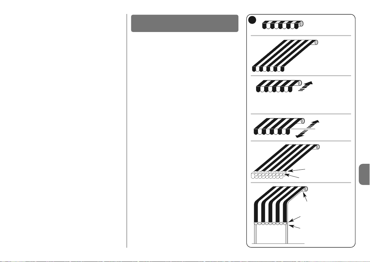
Polski – 3
PL
Markiza całkowicie zamknięta (Poz. “0”)
Zasłona otwarta (Poz. “1”)
Zapamiętuje
pośrednią pozycję (“I”)
Położenie początkowe redukcji momentu obrotowego RDC podczas manewru zamykania (to
położenie nie może być programowane)
Pozycja “2” dla
funkcji “FRT”
Pozycja odczepu
“S” dla markiz,
które są napinane za pomocą
mechanizmu automatycznego
zaczepu
“0”
“A”
“2”
“1”
“S”
E
2.1.5 - Czujniki pogodowe (czarno/biały +
pomarańczowo/biały)
Do wejścia “Czujniki pogodowe” (pomiędzy Wspólnym i
wejściem Czujników pogodowych) podłączyć można prosty czujnik wiatrowy (anemometr) lub specjalny czujnik
wiatr-slonce-deszcz.
W przypadku używania czujników wiatru jest możliwe podłączenie do tego samego czujnika do 5 silników lub central,
wykorzystując połączenie równoległe (przestrzegaj biegunowości sygnałów).
Uwaga! - Pomimo, że jest to możliwe nie zaleca się podłączania jednego czujnika słońca do kilku silników. Istotnie,
nawet jeśli progi różnych silników są wyregulowane na tę
samą wartość, każdy silnik wykonuje własny pomiar i automatyczne operacje markiz nie byłyby wykonywane jednocześnie.
Aby wprawić w ruch kilka silników jednocześnie należy wy korzystać czujniki z własną regulacją progu, jak na przykład
modele Volo ST, Volo S Radio i Nemo.
2.2 - Kierunek wyjścia przewodu (rys. C)
(Tylko dla modelu NEOMAT-LT) – W celu dokonania
zmiany kierunku wyjścia przewodu wystarczy: 01. Wysu-
nąć osłonę w kierunku do góry. 02. Wygiąć przewód w
żądanym kierunku. 03. Założyć osłonę dociskając ją na siłę
do jej gniazda.
2.3 - Złącze i przewód zasilający
(Tylko dla modelu NEOMAT-MT) – Informacje zawarte w
tym rozdziale są przeznaczone wyłącznie dla personelu te chnicznego serwisu.
UWAGA! - Gdy przewód zasilający jest uszkodzony na leży go wymienić na identyczny dostępny u producenta lub w serwisie technicznym.
Jeżeli stanie się konieczne odłączenie silnika od przewodu
zasilającego postępuj w następujący sposób (rys. D): a) Przekręcić tuleją do momentu dopasowania nacięcia do
jednego z ząbków zaczepu, po czym odczepić. b) - Po wtórzyć czynność dostosowania do następnego ząbka. c)
- Zgiąć przewód w kierunku do wnętrza i ściągnąć zabez-
pieczenie odkręcając delikatnie w kierunku na ze wnątrz. d)
- Po ciągnąć i wyciągnąć łącze.
Siłowniki rurowe serii NEOMAT przewidują zastosowanie
systemu wyłączników krańcowych elektromechanicznych,
które przerywają ruch, gdy markiza lub roleta osiąga pozycje końcowe otwarcia lub zamknięcia. Te pozycje mają być
wczytane odpowiednią fazą programowania, która ma być
wykonana w siłowniku zamontowanym i z całkowicie zainstalowaną markizą.
(rys. E) Jeśli pozycje “0” (markiza zamknięta) i “1” (markiza
otwarta) nie zostały jeszcze wczytane można również sterować siłownikiem, ale ruch ma być wykonany ręcznie.
Jest również możliwe zaprogramowanie następujących
położeń:
• Położenie pośrednie “I” umożliwiające częściowe otwar-
cie markizy. To położenie może być programowane również w innym czasie.
• Pozycja “2” niezbędna do uaktywnienia funkcji “FRT”
służy do naciągania płótna, kiedy markiza jest całkowicie
otwarta.
• Funkcja “FTC” do automatyzacji markiz z mechanizmem
do automatycznego zaczepiania.
3
Regulacje

4 – Polski
PL
Faza programowania podzielona jest na 3 części:
1. Wczytywanie nadajników
2. Automatyczne programowanie pozycji “0” i “1”
3. Programowanie opcjonalne
Aby nadajnik mógł sterować siłownikiem serii NEOMAT-T koniecznym jest przeprowadzenie fazy programowania w sposób wskazany w tabeli A1.
UWAGA:
• Wszystkie sekwencje zapisywania odbywają się na czas, co oznacza, że należy je
wykonać w granicach przewidzianego czasu.
• W przypadku nadajników obsługujących więcej “grup”, przed przystąpieniem do progra-
mowania należy dokonać wyboru grupy nadajnika, do której siłownik zostanie dostosowany.
• Wczytywanie poprzez fale radiowe odbędzie się we wszystkich odbiornikach, jakie znaj-
dują się w promieniu zasięgu nadajnika; wskazane jest więc, aby był zasilany tylko ten,
którego czynność ma dotyczyć.
Można sprawdzić, czy w siłowniku są już wczytane nadajniki; w tym celu wystarczy
sprawdzić ilość sygnałów akustycznych “Bip”, wydanych w chwili włączania siłownika:
- 2 długie Bip = Brak wczytanego nadajnika.
- 2 krótkie Bip = Już istnieją wczytane nadajniki.
4.1 - Programowanie nadajników
––––––––––––––––––––––––––––––––––––––––––––––––––––––––––––––––––––––––––––
Tabela “A1” - Wczytywanie pierwszego nadajnika (w Trybie I)
––––––––––––––––––––––––––––––––––––––––––––––––––––––––––––––––––––––––––––
01. Podłączyć siłownik do zasilania sieciowego, natychmiast
usłyszymy 2 długie Bip.
02. W ciągu do 5 sekund przycisnąć i utrzymać pod naci-
skiem przycisk ■ nadajnika,
który chcemy wczytać (przez około 3 sekundy).
03. Zwolnić przycisk ■ przy pierwszym z trzech Bip, które
potwierdzają wczytanie.
Aby wczytać pozostałe nadajniki patrz tabela A2.
Gdy jeden lub więcej nadajników został już wczytany, możliwe jest wczytanie innych w
sposób podany w tabeli A2.
4
Programowanie
––––––––––––––––––––––––––––––––––––––––––––––––––––––––––––––––––––––––––––
Tabela “A2” - Wczytywanie pozostałych nadajników (w Trybie I)
––––––––––––––––––––––––––––––––––––––––––––––––––––––––––––––––––––––––––––
01. Wcisnąć i przytrzymać przycisk ■ nowego nadajnika
(około 5 sekund), aż do usłyszenia Bip; następnie zwolnić przycisk ■ .
02. Powoli 3 krotnice przycisnąć przycisk ■ starego nadajni-
ka już wczytanego.
03. Wcisnąć ponownie przycisk ■ nowego nadajnika. Zwol-
nić przycisk ■ po pierwszym z 3 Bip, które potwierdzają
wczytanie.
Uwaga: jeśli pamięć urządzenia jest zapełniona (14 nadajników) usłyszy się 6 Bip i nadajnik nie będzie mógł zostać wczytany.
4.2 - Programowanie pozycji “0” i “1”
Aby zaprogramować pozycje należy zastosować pilot już wczytany w Trybie I. Dopóki do
centrali nie zostaną wczytane prawidłowe pozycje “0” i “1” ruch może być wykonany tylko
ręcznie. Na początku kierunek silnika nie jest określony, ale po skompletowaniu punktu 1 z
tabeli “A3” kierunek silnika zostanie automatycznie dostosowany do przycisków nadajników.
Aby zaprogramować pozycje 0 i 1 wykonać procedurę skazaną w tabeli “A3”.
––––––––––––––––––––––––––––––––––––––––––––––––––––––––––––––––––––––––––––
Tabela “A3” - Automatyczne programowanie pozycji “0” i “1”
––––––––––––––––––––––––––––––––––––––––––––––––––––––––––––––––––––––––––––
01. Przycisnąć i utrzymać pod naciskiem przycisk ▲ lub
przycisk ▼ pilota wczytanego aż do momentu całkowitego nawinięcia się markizy i automatycznego zatrzymania się siłownika.
02. Przycisnąć i utrzymać pod naciskiem przycisk ▼, który
opuszcza zasłonę.
03. Zwolnić przycisk ▼ kiedy markiza dojdzie do żądanej
pozycji (“1”). Jeśli jest to konieczne wyregulować pozycje przyciskiem ▼ i ▲.
04. Przytrzymać wciśnięty przycisk ■ nadajnika aż do usły-
szenia Bip (po około 5 sekundach).
05. Zwolnić i ponownie przycisnąć na następne 5 sekund
przycisk ■ do usłyszenia 4 szybkich Bip.
06. Przycisnąć przycisk ▼ do momentu usłyszenia 3 Bip, a
krotki ruch nawijania lub obniżania zasygnalizuje, ze wartość została wczytana.
3s...
5s...
x 3
nowy
stary
nowy
5s...
5s...

Polski – 5
PL
4.3 - Programowanie opcjonalne
Wszystkie programowania opcjonalne są możliwe tylko po zaprogramowaniu pozycji “0” i “1”.
4.3.1 - Zapamiętuje pośrednią pozycję “I”
Kiedy już jest wczytana pozycja pośrednia “I” można będzie poruszyć markiza do pozycji
“I” jednoczesnym wciśnięciem 2 przycisków ▲ ▼ nadajnika.
Aby wczytać pozycje pośrednia należy wykonać procedurę wskazana w tabeli “A4”:
––––––––––––––––––––––––––––––––––––––––––––––––––––––––––––––––––––––––––––
Tabela “A4” - Programowanie pośrednią pozycję “I”
––––––––––––––––––––––––––––––––––––––––––––––––––––––––––––––––––––––––––––
01. Przyciskając przyciski ▲ ■ ▼ nowego nadajnika ustawić
mar kizę na pozycji jaka zamierza się wczytać jako pozycje “I”.
02. Przytrzymać wciśnięty przycisk ■ nadajnika aż do usły-
szenia Bip (po około 5 sekundach).
03. Zwolnić i ponownie przycisnąć na następne ■ sekund
przycisk 5 do usłyszenia 4 szybkich Bip.
04. Przycisnąć jednocześnie przyciski ▼▲do momentu,
kiedy 3 Bip zasygnalizują, że wartość została wczytana.
4.3.2 - Dezaktywacja lub ponowna aktywacja redukcji momentu obrotowego
podczas zamykania (RDC)
Redukcja momentu obrotowego jest funkcją, która powoduje zredukowanie momentu rozciągającego o około 50% krótko przed całkowitym zwinięciem markizy w skrzynce nadokiennej, aby w ten sposób zapobiec nadmiernemu wyciąganiu płótna. Ta funkcja jest uaktywniana automatycznie po zaprogramowaniu wartości 0 i 1 (programowanie następuje
zawsze przy maksymalnej sile), ale może być dezaktywowana (lub ponownie uaktywniana).
Uwaga - automatyczne uaktywnienie funkcji RDC nie nastąpi, jeżeli programowanie położeń jest wykonywane z pomocą programatorów TTP, TTI i O-ViewTT; w tych przypadkach,
jeżeli jest to wymagane, funkcja może być uaktywniana w trybie ręcznym.
––––––––––––––––––––––––––––––––––––––––––––––––––––––––––––––––––––––––––––
Tabela “A5” - Dezaktywacja lub ponowna aktywacja redukcji momentu obro-
towego (RDC)
––––––––––––––––––––––––––––––––––––––––––––––––––––––––––––––––––––––––––––
01. Przytrzymać wciśnięty przycisk ■ nadajnika już wczyta-
nego aż do usłyszenia Bip (około 5 sekund).
02. Zwolnić i ponownie przycisnąć na następne 5 sekund
przycisk ■ do usłyszenia 4 szybkich Bip.
03. Wciśnij przycisk ■, aż do rozpoczęcia sygnałów dźwię-
kowych: 3 sygnały dźwiękowe wskazują RDC aktywny
(zamykanie przy zredukowanym momencie obrotowym);
5 sygnałów wskazuje RDC nieaktywny (zamykanie przy
maksymalnym momencie obrotowym).
4.3.3 - Kasowanie położeń
Aby zmodyfikować pozycje wcześniej wczytane należy najpierw skasować, a następnie
ponownie zaprogramować nowe pozycje.
––––––––––––––––––––––––––––––––––––––––––––––––––––––––––––––––––––––––––––
Tabela “A6” - Kasowanie Pośredniej pozycji “I”
––––––––––––––––––––––––––––––––––––––––––––––––––––––––––––––––––––––––––––
01. Przytrzymać wciśnięty przycisk ■ nadajnika wczytane-
go, aż do usłyszenia Bip (około 5 sekund).
02. Zwolnić i ponownie przycisnąć na następne ■ sekund
przycisk 5 do usłyszenia 4 szybkich Bip.
03. Przycisnąć jednocześnie przyciski ▼ ▲ do momentu,
kiedy 5 Bip zasygnalizują, ze pozycja pośrednia już
została skasowana.
––––––––––––––––––––––––––––––––––––––––––––––––––––––––––––––––––––––––––––
Tabela “A7” - Kasowanie pozycji “0” i “1”
––––––––––––––––––––––––––––––––––––––––––––––––––––––––––––––––––––––––––––
01. Przytrzymać wciśnięty przycisk ■ nadajnika wczytanego
aż do usłyszenia Bip (około 5 sekund).
02. Zwolnić i ponownie przycisnąć na następne ■ sekund
przycisk 5 do usłyszenia 4 szybkich Bip.
03. Przycisnąć przycisk ▼ do momentu, kiedy 5 Bip zasy-
gnalizują, ze pozycje “0” i “1” zostały skasowane.
UWAGA: Po skasowaniu położeń “0” i “1” markiza będzie się przesuwać w trybie ręcznym
i stanie się konieczne wczytanie nowych położeń.
Uwaga: Nie zostaną skasowane pozycje pośrednie “I” i ewentualnie zaprogramowana
funkcja RDC. Jeśli zamierza się skasować wszystko (wraz z kodami nadajników) kierować
się wskazówkami z tabeli “A14”.
4.3.4 - Programowanie poziomu interwencji czujnika pogodowego “wiatr”
Jeśli do wejścia “czujniki” podłączony zostanie czujnik wiatru z serii “VOLO” lub “VOLO S”,
uruchamia się zabezpieczenie “wiatru”, to znaczy automatyczne wycofanie markizy w
przypadku, gdy siła wiatru przekracza zaprogramowany poziom. Jeśli poziom zostanie
przekroczony przez ponad 3 sekundy, uruchamia się polecenie odpowiadające przyciskowi ▲ i zablokowany zostaje każdy inny ruch do chwili, gdy wiatr nie powróci poniżej zaprogramowanego poziomu na przynajmniej 1 minutę. Możliwe jest wybranie poziomu zadziałania spośród 5 poziomów: 1=5km/godz, 2=10km/godz, 3=15km/godz, 4=30km/godz e
5=45km/godz. (poziom fabryczny to nr 3).
W przypadku zastosowania czujnika “VOLO ST” lub czujników radiowych Volo S Radio i
Nemo, progi zadziałania wiatru są programowane bezpośrednio w czujniku (przeczytaj
odpowiednie instrukcje obsługi).
Aby zmienić zaprogramowany poziom:
5s...
5s...
5s...
5s...
5s...
5s...
(...)
5s...
5s...
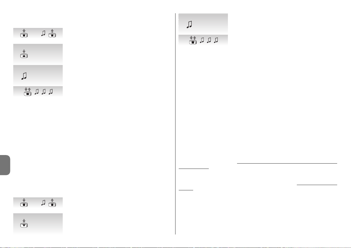
6 – Polski
PL
––––––––––––––––––––––––––––––––––––––––––––––––––––––––––––––––––––––––––––
Tabela “A9” - Zmienić poziom interwencji zabezpieczenia “wiatr”
––––––––––––––––––––––––––––––––––––––––––––––––––––––––––––––––––––––––––––
01. Przytrzymać wciśnięty przycisk ■ nadajnika wczytanego
(około 5 sekund) aż do usłyszenia Bip; następnie zwolnić
przycisk ■ .
02. Wcisnąć powoli przycisk ▲ tyle razy (1, 2, 3, 4 lub 5) ile
wynosi numer wybranego poziomu.
03. Po kilku chwilach da się słyszeć ilość Bip równa wybra-
nemu numerowi poziomu.
04. Wcisnąć i zwolnić przycisk ■ dla zatwierdzenia.
Jeśli w punkcie 3 nie słychać ilości Bip równej numerowi wybranego poziomu, wystarczy nie
wciskać żadnego przycisku i odczekać kilka sekund w celu zakończenia bez zmiany poziomu.
4.3.5 - Programowanie poziomu interwencji czujnika “słońce”
Jeśli do wejścia “czujniki” podłączony zostanie czujnik słońca” VOLO-S” uruchamia się
automatyka “słońce”, to znaczy automatyczne opuszczanie markizy w przypadku, gdy
“słońce” przekroczy zaprogramowany poziom. Jeśli poziom zostanie przekroczony przez
ponad 2 minuty, uruchamia się polecenie odpowiadające przyciskowi ▼; następnie, jeśli
“słońce” opada poniżej zaprogramowanego poziomu na 15 minut, uruchamia się polecenie odpowiadające przyciskowi ▲.
Możliwe jest wybranie poziomu zadziałania “słońce” spośród 5 poziomów: 1=5Klux,
2=10Klux, 3=15Klux, 4=30Klux e 5=45Klux (fabrycznie ustawiony jest poziom 3).
––––––––––––––––––––––––––––––––––––––––––––––––––––––––––––––––––––––––––––
Tabela “A10” - Zmiana poziomu zadziałania automatyki “słońce”
––––––––––––––––––––––––––––––––––––––––––––––––––––––––––––––––––––––––––––
W przypadku zastosowania czujnika “VOLO ST” lub czujników radiowych Volo S Radio i
Nemo, progi zadziałania słońca są programowane bezpośrednio w czujniku (przeczytaj
odpowiednie instrukcje obsługi).
01. Przytrzymać wciśnięty przycisk ■ nadajnika wczytanego
(około 5 sekund) aż do usłyszenia Bip; następnie zwolnić
przycisk ■ .
02. Wcisnąć powoli przycisk ▼ tyle razy (1, 2, 3, 4 lub 5) ile
wynosi numer wybranego poziomu.
03. Po kilku chwilach usłyszy się ilość Bip równa wybranemu
numerowi poziomu.
04. Wcisnąć i zwolnić przycisk ■ dla zatwierdzenia.
Jeśli w punkcie 3 nie słychać ilości Bip równej numerowi wybranego poziomu, wystarczy
nie wciskać żadnego przycisku i odczekać kilka sekund w celu zakończenia fazy ale bez
zmiany poziomu.
4.3.6 - Zmiana kierunku zadziałania w przypadku deszczu
Jeżeli będzie używany czujnik deszczu Nemo WSRT, w przypadku odczytania obecności
deszczu wysyła on informację do silników i steruje ruchem w zaprogramowanym kierunku
(fabrycznie został zaprogramowany kierunek “podnoszenie”).
Aby zmienić kierunek zadziałania w przypadku deszczu:
01. Przytrzymaj wciśnięty przycisk ■ nadajnika już wczytanego, dopóki nie zostanie usły-
szany sygnał dźwiękowy (po około 5 sekundach); wówczas zwolnij przycisk.
02. Powoli wciśnij ten sam przycisk ■ jeszcze 3 razy.
03. Wciśnij przycisk z wybranym kierunkiem (podnoszenie lub opuszczanie), teraz silnik
wykona 3 sygnały dźwiękowe = nowy kierunek wczytany.
Operacje automatyczne powodowane przez czujnik “słońca2 mogą być dezaktywowane z po mocą polecenia “Słońce OFF” wysyłanego z nadajnika, który dysponuje tą funkcją (Ergo 4, Pla no 4, WM004G), jest możliwe ponowne jego uaktywnienie z pomocą polecenia “Słońce ON”.
Do operacji automatycznych powodowanych przez czujnik “słońca” mogą być dodawane
w każdej chwili również polecenia w trybie ręcznym, wysyłane przez użytkownika z zastosowaniem zwykłego nadajnika; przeważają one nad poleceniami wysyłanymi przez
czujnik “słońca”, w trybie opisanym w poniższym przykładzie: jeżeli markiza znajduje się w
położeniu “1” (uzyskanym automatycznie w wyniku przekroczenia progu “słońca”) i w nied ługim czasie użytkownik wysteruje jej podnoszenie do położenia “0”, w późniejszym czasie,
również, jeśli system nadal odczytuje przekroczenie progu “słońca”, nie powoduje ruchów
markizy (pozostaje ona w położeniu wysterowanym przez użytkownika).
“Cykl automatyczny” przerwany przez polecenie wysłane w trybie ręcznym jest resetowany w przypadku, kiedy poziom natężenia światła znajdzie się poniżej progu (zwykle po
zachodzie słońca).
4.3.7 - Programowanie funkcji “FRT”
Po zaprogramowaniu pozycji “0” i “1”, na życzenie można zaprogramować pozycję “2”,
która uaktywnia funkcję cofania się płótna FRT.
Aby zaprogramować pozycje “2” wykonać procedurę wskazaną w tabeli “A11”
5s...
5s...
x 1 = 5 Km/h
x 2 = 10 Km/h
x 3 = 15 Km/h
x 4 = 30 Km/h
x 5 = 45 Km/h
x 1 = 5 Km/h
x 2 = 10 Km/h
x 3 = 15 Km/h
x 4 = 30 Km/h
x 5 = 45 Km/h
x 1 = 5 Klux
x 2 = 10 Klux
x 3 = 15 Klux
x 4 = 30 Klux
x 5 = 45 Klux
x 1 = 5 Klux
x 2 = 10 Klux
x 3 = 15 Klux
x 4 = 30 Klux
x 5 = 45 Klux
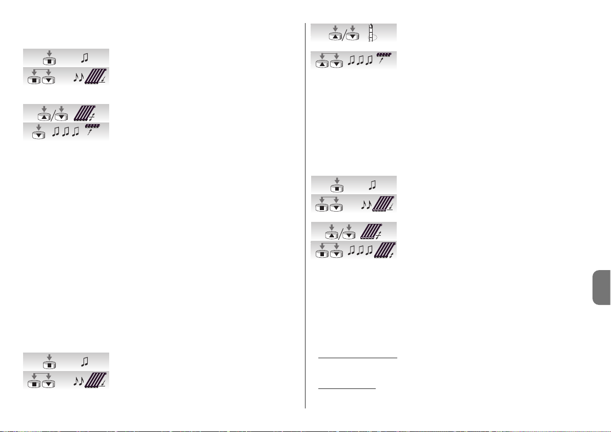
Polski – 7
PL
––––––––––––––––––––––––––––––––––––––––––––––––––––––––––––––––––––––––––––
Tabela “A11” - Programowanie pozycji “2”
––––––––––––––––––––––––––––––––––––––––––––––––––––––––––––––––––––––––––––
01. Przytrzymać wciśnięty przycisk ■ nadajnika już wczyta-
nego aż do usłyszenia Bip (około 5 sekund).
02. Wcisnąć i przytrzymać przyciski ■▼na następne 5 se -
kund nadajnika aż do usłyszenia 2 szybkich Bip. W tym
momencie markiza ustawi się automatycznie na dolne
pozycji krańcowej (pozycja “1”).
03. W ciągu do 5 sekund przycisnąć przycisk ▼ i ▲ aby
ustawić markizę żądanej pozycji.
04. Potwierdzić w ciągu do 5sekund pozycje przyciskając
przycisk ■ nadajnika aż do usłyszenia 3 Bip. Następnie
markiza ustawi się na zaprogramowanej dolnej pozycji
krańcowej (pozycja “1”).
Uwaga: Jeśli programowanie nie zostanie potwierdzone tak, jak opisano w punkcie 4 to
zmiany zostaną skasowane i potwierdzone zostanie programowanie poprzednie.
Gdy zaraz po zaprorgamowaniu tej funkcji zamierza się ją skasować należy wykonać procedurę wskazaną w tabeli A13, omijająć nr 3 czyli bez modyfikacji pozycji “1”.
Kiedy zostanie zaprogramowana pozycja “2”, centrala elektroniczna automatycznie oblicza
różnice pomiędzy pozycja “2” i pozycja “1” w taki sposób, ze po każdym poleceniu na obniżanie markiza obniży się do dalszej pozycji i później “odzyskuje” płótno do pozycji bliższej.
4.3.8 - Programowanie funkcji “FRT”
Po zaprogramowaniu pozycji “0” i “1”, na życzenie można zaprogramować pozycję “S”,
która uaktywnia funkcję “FTC” do automatyzacji markiz posiadających mechanizm do
zaczepu automatycznego. Aby mechanizm działał prawidłowo należy, aby pozycja “1” była
zaprogramowana na odległości o kilka centymetrów po pozycji zaczepu w taki sposób,
aby przy podnoszeniu się od punktu “1” nastąpiło zahaczenie; aby pozycja “S” była zaprogramowana na kilka centymetrów po pozycji odczepu, w taki sposób, aby wznoszenie się
od “S” odbywało się w sposób swobodny.
Aby zaprogramować pozycje “S” wykonać procedurę wskazaną w tabeli “A12”.
––––––––––––––––––––––––––––––––––––––––––––––––––––––––––––––––––––––––––––
Tabela “A12” - Programowanie Pozycji odczepu “S”
––––––––––––––––––––––––––––––––––––––––––––––––––––––––––––––––––––––––––––
01. Przytrzymać wciśnięty przycisk ■ nadajnika już wczyta-
nego aż do usłyszenia Bip (około 5 sekund).
02. Wcisnąć i przytrzymać przycisk ■▼ na następne 5
sekund aż do usłyszenia 2 szybkich Bip. W tym miejscu
markiza automatycznie ustawi się na pozycji “1”.
03. W ciągu do 5 sekund przycisnąć przycisk ▼ i ▲ aby
ustawić markizę żądanej pozycji do odczepu “S” (poniżej
pozycji “1”).
04. Potwierdzić w ciągu do 5 sekund pozycje przyciskając jed-
nocześnie przyciski ▼ i ▲ aż do usłyszenia 3 Bip. W tym
miejscu markiza automatycznie ustawi się na pozycji “0”.
Uwaga: Jeśli programowanie nie zostanie potwierdzone tak, jak opisano w punkcie 4 to
zmiany zostaną skasowane i potwierdzone zostanie programowanie poprzednie.
Jeśli jednak po zaprogramowaniu tej funkcji chcemy ja usunąć wykonać należy procedurę
wskazaną w tabeli A13, ignorując punkt nr 3, czyli bez zmiany pozycji “1”.
4.3.9 - Zmiana pozycji “1”
Aby zaprogramować pozycje “1” wykonać procedurę wskazaną w tabeli “A13”:
––––––––––––––––––––––––––––––––––––––––––––––––––––––––––––––––––––––––––––
Tabela “A13” - Zmiana pozycji “1”
––––––––––––––––––––––––––––––––––––––––––––––––––––––––––––––––––––––––––––
01. Przytrzymać wciśnięty przycisk ■ nadajnika już wczyta-
nego aż do usłyszenia Bip (około 5 sekund).
02. Wcisnąć i przytrzymać przycisk ■ i ▼ na następne 5
sekund aż do usłyszenia 2 szybkich Bip. W tym miejscu
markiza automatycznie ustawi się na pozycji “1”.
03. W ciągu do 5 sekund przycisnąć przycisk ▼ i ▲ aby
ustawić markizę nowej do zaprogramowania pozycji.
04. Potwierdzić w ciągu do 5 sekund pozycje przyciskając
jednocześnie przycisk ■ i ▼ nadajnika aż do usłyszenia
3 Bip i krótkiego ruchu obniżania.
Uwaga: jeśli programowanie nie zostanie potwierdzone tak, jak opisano w punkcie 4, to
zmiany zostaną skasowane i potwierdzone zostanie programowanie poprzednie.
Modyfikując pozycje “1” kasuje się również funkcje “FRT” i “FTC”.
4.4 - Kasowanie pamięci
Jeśli okazałoby się konieczne skasowanie nadajników i programowania, można przeprowadzić sekwencję wskazaną w tabeli A14.
Kasowanie jest możliwe
:
• przy pomocy nadajnika nie wczytanego przez rozpoczęcie procedury od punktu A.
• przy pomocy nadajnika już wczytanego przez rozpoczęcie procedury od punktu 1.
Można skasować
:
• tylko nadajniki wczytane, kończąc na punkcie A.
• wszystko (nadajniki, poziom czujników, adres, TTBUS...), kończąc procedurę na punkcie 6.
5s...
5s...
5s...
5s...
5s...
1
S
5s...
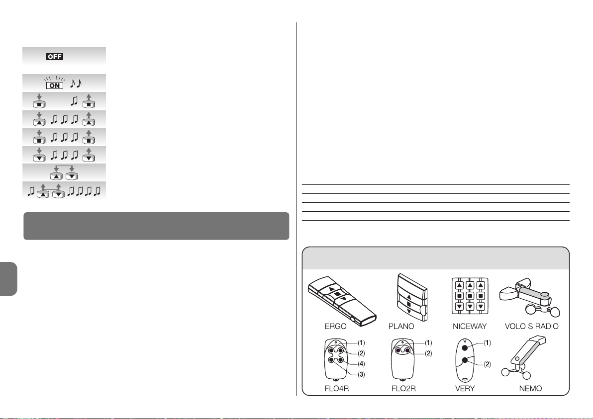
8 – Polski
PL
Tabela “A15”
––––––––––––––––––––––––––––––––––––––––––––––––––––––––––––––––––––––––––––
Tabela “A14” - Kasowanie pamięci
––––––––––––––––––––––––––––––––––––––––––––––––––––––––––––––––––––––––––––
A. W nie zasilanym siłowniku uruchomić wejście Krok po
kroku (połączyć przewód biały z biało/czarnym) i przytrzymać złączone do samego końca procedury.
B. Podłączyć siłownik do zasilania sieciowego i odczekać
na początkowe Bip.
01. Wcisnąć i przytrzymać przycisk ■ nadajnika (około 5 se -
kund) aż do usłyszenia Bip, następnie zwolnić przycisk ■ .
02. Przytrzymać wciśnięty przycisk ▲ nadajnika aż do usłysze-
nia 3 Bip. Zwolnić przycisk ▲ dokładnie przy trzecim Bip.
03. Przytrzymać wciśnięty przycisk ■ nadajnika aż do usłysze-
nia 3 Bip. Zwolnić przycisk ■ dokładnie przy trzecim Bip.
04. Przytrzymać wduszony przycisk ▼ nadajnika aż usłysze-
nia 3 Bip. Zwolnić przycisk ▼ dokładnie przy trzecim Bip.
05. Aby skasować wszystko: w ciągu 2 sekund wcisnąć te
same przycisk ▲ i ▼.
06. Zwolnić przycisk ▲ i ▼ przy pierwszym z 5 Bip, które
potwierdzają kasowanie.
Siłowniki serii NEOMAT-T, rozpoznają nadajniki serii ERGO, PLANO, NICEWAY, VOLO S
RADIO oraz NEMO, (patrz rozdział 5.1 “Stosowane nadajniki”).
Ponadto przy pomocy odpowiednich procedur wczytywania nadajników możliwe jest także przypisanie każdemu z przycisków nadajnika konkretnej funkcji (patrz rozdział 5.2 “Programowanie nadajników w trybie I i w trybie II”).
Uwaga: do programowania nadają się tylko nadajniki wczytane w trybie I.
5.1 - Stosowane nadajniki
W tabeli A15 podane są nadajniki, które mogą być stosowane wraz z odpowiednim rodzajem kodowania.
––––––––––––––––––––––––––––––––––––––––––––––––––––––––––––––––––––––––––––
Tabela “A15” - Nadajniki
• ERGO1 - ERGO4 - ERGO6 • PLANO1 - PLANO4 - PLANO6 - PLANO TIME • VOLO S
RADIO • NEMO • NICEWAY (cała linia) • FLO1R - FLO2R - FLO4R • VERY VR •
––––––––––––––––––––––––––––––––––––––––––––––––––––––––––––––––––––––––––––
5
Rozszerzenie wiadomości
5.2 - Wczytywanie nadajników w trybie I oraz w trybie II
W tabelach “A1” oraz “A2” opisane zostało wczytywanie nadajników w trybie I, w którym
każdemu przyciskowi przypisane jest konkretne polecenie. przycisk ▲ (1) = “podnoszenie”; przycisk ■ (2) = “stop”; przycisk ▼ (3) = “opuszczanie”.
Możliwe jest wczytanie nadajników także w trybie II, ten tryb pozwala na większą elastyczność w stosowaniu przycisków nadajników. Do jednego siłownika serii NEOMAT-T można
wczytać bądź nadajniki w trybie I jak i w trybie II.
5.2.1 - Tryb I
W trybie I polecenie powiązane z przyciskiem nadajnika jest stałe: przycisk ▲ (1) steruje
“Podnoszeniem”; przycisk ■ (2) steruje “Stop”; przycisk ▼ (3) steruje “Opuszczaniem”,
ewentualny przycisk 4 steruje “Stop”.
W trybie I wykonywana jest tylko jedna faza wczytywania dla każdego z nadajników, a w
pamięci zajęte zostaje tylko jedno miejsce. Podczas wczytywania w trybie I nie ma znaczenia, który z przycisków zostanie wciśnięty.
W celu wczytania lub skasowania nadajników w trybie I patrz tabele A1 oraz A2.
Przycisk Polecenie
Przycisk ▲ lub 1 Podnoszenie (nawijanie)
Przycisk ■ lub 2 Stop
Przycisk ▼ lub 3 Opuszczanie
Przycisk 4 Stop
P. P.
5s...
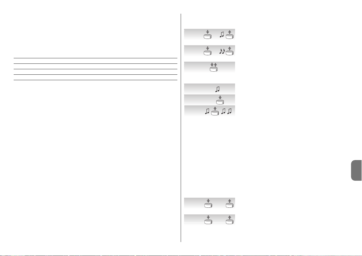
Polski – 9
PL
5.2.2 - Tryb II
W trybie II możliwe jest przypisanie każdemu z przycisków nadajnika jednego z 4 możliwych poleceń: 1 = Krok po kroku; 2 = Podnoszenie - stop; 3 = Opuszczanie - stop, 4 =
Stop. W trybie II wykonywana jest oddzielna faza wczytywania dla każdego z przycisków i
każdy z nich zajmuje osobne miejsce w pamięci. Podczas wczytywania w trybie II wczytany zostanie dopiero co wciśnięty przycisk. Jeśli zamierza się przypisać innemu przyciskowi
tego samego nadajnika inne polecenie konieczne jest ponowne wczytanie.
Nr Polecenie
1 Krok po kroku (podnoszenie - stop - opuszczanie – stop
2 Podnoszenie - stop (podnoszenie - stop - podnoszenie - stop...)
3 Opuszczanie - stop (opuszczanie - stop - opuszczanie - stop..)
4 Stop
5.2.3 - Przykład wczytywania mieszanego trybu I oraz trybu II
Korzystając odpowiednio z wczytywania w trybie I oraz w trybie II możliwe jest utworzenie
poleceń grupowych, jak to przykładowo podano na rys. F.
• Nadajnik T1 (Ergo1) wczytany w trybie I do A1 oraz A2 steruje podnoszeniem, stopem
lub opuszczaniem jednocześnie tak dla A1 jak i A2.
• Nadajnik T2 (Plano1) wczytany w trybie I do tylko do A3 steruje podnoszeniem, stopem
lub opuszczaniem tylko dla A3.
• Nadajnik T3 (Planotime) wczytany w trybie I tylko do A4 steruje podnoszeniem, stopem,
lub opuszczaniem tylko dla A4.
• Nadajnik T4 (WM001C) wczytany w trybie II (Krok po kroku) steruje tylko A4.
• Nadajnik T5 (WM003G) wczytany w trybie I dla sterowania, wraz grupą I dla A1 oraz A2,
z grupą 2 dla A3 oraz z grupą 3 dla A4; steruje podnoszeniem, stopem, lub opuszczaniem dla A1 oraz A2, A3 lub też dla A4.
• Nadajnik T6 (Flo4R) wczytany w trybie II w A4 (przyciski 1 i 3) w A5 (przycisk 2) oraz w
A6 (przycisk 4) steruje podnoszeniem i opuszczaniem dla A4, lub też otwarciem bramy
garażowej A5 lub też otwarciem ruchomej bramy automatycznej A6.
UWAGA:
• Przy pomocy nadajnika wczytanego w trybie II nie jest możliwe dokonywanie progra-
mowania niektórych funkcji (pozycji, poziomów,...) jeśli w danym programowaniu wymagane jest wciśnięcie innych przycisków, na przykład przycisku ■ oraz przycisku ▲.
• Przy pomocy nadajnika wczytanego w trybie II nie można stosować poleceń “grupy
wieloelementowej”.
Kiedy jeden lub więcej nadajników zostało już wczytanych, inne można umieścić w pamięci w trybie II, tak jak to pokazano w tabeli A16.
––––––––––––––––––––––––––––––––––––––––––––––––––––––––––––––––––––––––––––
Tabela “A16” - Wczytywanie dodatkowych nadajników w trybie II
––––––––––––––––––––––––––––––––––––––––––––––––––––––––––––––––––––––––––––
01. Wcisnąć i przytrzymać przycisk do wczytania nowego
nadajnika (około 5 sekund) aż do usłyszenia Bip; następnie zwolnić przycisk.
02. W ciągu 5 sekund wcisnąć i przytrzymać wczytany już
przycisk starego nadajnika (około 5 sekund) aż do usłyszenia 2 krótkich “Bip”, następnie przycisk zwolnić.
03. W ciągu 5 sekund rozpocząć wciskanie tego przycisku
starego nadajnika tyle razy ile wynosi numer żądanej
funkcji: 1= “krok po kroku” 2 = “podnoszenie” 3 = “opu szc zanie” 4 = “stop”.
04. Po około 3 sekundach usłyszymy ilość Bip równą nume-
rowi wybranego polecenia.
05. W ciągu 2 sekund wcisnąć ten sam przycisk nowego
nadajnika.
06. Zwolnić przycisk przy pierwszym z trzech Bip, które
potwierdzają wczytanie.
Jeśli w punkcie 5 nie słychać ilości Bip równej numerowi wybranego polecenia, wystarczy
nie wciskać żadnego przycisku i odczekać kilka sekund w celu zakończenia programowania bez żadnego wczytywania.
Uwaga: jeśli pamięć urządzenia jest zapełniona (14 nadajników), to usłyszy się 6 Bip i
nadajnik nie będzie mógł zostać wczytany.
Możliwe jest wczytanie w prosty sposób nowego nadajnika przy zachowaniu charakterystyk starego nadajnika postępując według procedury z tabeli A17. Nowy nadajnik wczytany w ten sposób odziedziczy charakterystyki starego, to znaczy, jeśli stary był wczytany w
trybie I, także i nowy pracował będzie w trybie I, jeśli stary został wczytany w trybie II, także przycisk nowego nadajnika zostanie dostosowany do tego samego polecenia, co stary.
––––––––––––––––––––––––––––––––––––––––––––––––––––––––––––––––––––––––––––
Tabela “A17” - Wczytywanie pozostałych nadajników
––––––––––––––––––––––––––––––––––––––––––––––––––––––––––––––––––––––––––––
01. Przycisnąć i przytrzymać przycisk do wczytania nowego
nadajnika przez przynajmniej 3 sekundy, następnie zwolnić przycisk.
02. Przycisnąć i przytrzymać już wczytany przycisk starego
nadajnika przez przynajmniej 3 sekundy, następnie przycisk zwolnić.
5s.
nowy
5s.
stary
1- 4
nowy
1- 43s.
nowy
>3s.
nowy
>3s.
stary

10 – Polski
PL
03. Przycisnąć i przytrzymać przycisk do wczytania nowego
nadajnika przez przynajmniej 3 sekundy, następnie zwolnić przycisk.
04. Przycisnąć i przytrzymać już wczytany przycisk starego
nadajnika przez przynajmniej 3 sekundy, następnie przycisk zwolnić.
05. Słychać będzie 3 Bip, które potwierdzają wczytanie
nowego nadajnika.
Uwaga: jeśli pamięć jest zapełniona (14 nadajników), to usłyszy się 6 Bip i nadajnik nie
będzie mógł zostać wczytany.
Produkt ten jest nierozłączną częścią automatyki, w związku z tym musi być poddany utylizacji wraz nią.
Podobnie jak przy instalacji, także przy zakończeniu użytkowania niniejszego produktu
czynności utylizacji powinny być wykonane przez personel wykwalifikowany.
Niniejszy produkt składa się z różnego rodzaju materiałów, niektóre z nich mogą być
powtórnie użyte, inne muszą zostać poddane utylizacji. Należy zasięgnąć informacji o systemach wtórnego przerobu i utylizacji, przewidzianych przez lokalne przepisy dla tej kategorii produktu.
Uwaga! – niektóre elementy produktu mogą zawierać substancje szkodliwe lub niebezpieczne, które pozostawione w środowisku mogłyby zaszkodzić środowisku lub zdrowiu
ludzkiemu.
Zgodnie ze wskazaniem symbolu na rysunku obok zabronione jest wyrzucanie
tego produktu razem z odpadami domowymi. W celu utylizacji produktu należy przeprowadzić “segregację odpadów” na potrzeby utylizacji, według metod
przewidzianych lokalnymi przepisami, lub zwrócić produkt sprzedawcy podczas zakupu nowego, równorzędnego produktu.
Uwaga! – lokalne przepisy mogą przewidywać poważne sankcje w przypadku samodzielnej likwidacji tego produktu.
❏ Po podłączeniu zasilenia siłownik nie wydaje żadnego Bip, a wejście Krok
po kroku nie steruje żadnym ruchem.
Sprawdzić, czy siłownik jest podłączony do przewidywanego napięcia sieciowego, jeśli napięcie jest właściwe prawdopodobnie ma miejsce ciężkie uszkodzenie i siłownik musi być
naprawiony w centrum obsługi.
❏ Po wydaniu polecenia siłownik nie wykonuje ruchu.
• Jeśli tuż przedtem działał być może zadziałało zabezpieczenie termiczne, wystarczy odczekać kilka minut, aby siłownik ostygł.
• Sprawdzić, czy nie zostały źle wyregulowane wyłączniki krańcowe, spróbować poruszyć
śrubami regulacyjnymi w kierunku ruchu wskazówek zegara (+) o kilka obrotów.
• Sprawdzić, czy działa wejście “Krok po kroku” łącząc na chwilę przewody biały i czar no/biały.
7
Cosa fare se... cioè piccola guida se qualcosa non va!
6
Smaltimento del prodotto
>3s.
stary
>3s.
nowy

Polski – 11
PL
Dane techniczne siłowników rurowych NEOMAT-MT oraz NEOMAT-LT
• Apięcie zasilenia i częstotliwość: Patrz dane techniczne na etykiecie każdego modelu
• Prąd i moc: Patrz dane techniczne na etykiecie każdego modelu
• Moment i prędkość: Patrz dane techniczne na etykiecie każdego modelu
• Średnica siłownika: NEOMAT-MT = 45mm; NEOMAT-LT = 58mm
• Dokładność (rozdzielczość) wyłącznika krańcowego: Powyżej 0,55
• Dokładność pozycji blokad wyłącznika krańcowego: Klasa 2 (± 5%)
• Wytrzymałość mechaniczna: Zgodnie z normą EN14202
• Czas pracy ciągłej: Maksymalnie 4 minuty
• Stopień zabezpieczenia: IP 44
• Temperatura pracy: -20 ÷ +55 °C
• Długość przewodu łączącego: 3 m
• Napięcie sygnałów (Krok po kroku, TTBUS): Około 24 V
• Poziomy czujnika wiatru (anemometru): 5 równych około 5, 10, 15, 30 lub 45 km/godz
(z anemometrami VOLO lub VOLO-S)
• Poziomy czujnika słońca: 5 równych około 5, 10, 15, 30 lub 45 Klux (z VOLO-S)
• Długość przewodów sygnałowych (Krok po kroku, TTBUS): maksimum 30 m jeśli w
pobliżu innych przewodów, w przeciwnym razie 100 m
• Częstotliwość odbiornika radiowego: 433.92 MHz
• Kodowanie odbiornika radiowego: 52 Bit rolling code FLOR e FLOR+INFO
• Ilość nadajników możliwych do wczytania: 14, w tym maksimum 3 czujniki pogodowe
VOLO-S-Radio
• Zasięg nadajników: szacowany na 150 m w terenie otwartym i 20 m wewnątrz budynków (*)
Uwagi:
–(*) Zasięg nadajników może być uzależniony od innych urządzeń, które funkcjonują w jego
pobliżu na tej samej częstotliwości (na przykład słuchawki radiowe, systemy alarmowe,
itp.), powodując zakłócenia z nadajnikiem. W tym przypadku Nice nie może udzielić żadnej gwarancji na rzeczywisty zasięg własnych urządzeń radiowych.
– Wszystkie przytoczone dane techniczne dotyczą temperatury otoczenia 20°C (±5°C).
– Nice S.p.a. zastrzega sobie prawo do wprowadzania zmian w produkcie, kiedykolwiek to
będzie konieczne, z zachowaniem tego samego przeznaczenia oraz funkcjonalności.
• Sprawdzić, czy jest wczytany przynajmniej jeden nadajnik sprawdzając, czy podczas uruchomienia siłownik wydaje krótkie Bip.
• Sprawdzić, czy istnieje “komunikacja” pomiędzy nadajnikiem a siłownikiem przytrzymując wciśnięty przycisk ■ (2) nadajnika (wczytanego lub nie) przez przynajmniej 5 sekund,
jeśli słychać Bip, oznacza to, że siłownik otrzymuje sygnał z nadajnika, zatem należy pr zejść do ostatniej kontroli; w przeciwnym przypadku wykonać najbliższą kontrolę.
• Sprawdzić poprawność emisji sygnału radiowego nadajnika przy pomocy tej próby praktycznej: wcisnąć przycisk i zbliżyć diodę pilota do anteny aparatu radiowego (najlepiej jeśli
jest to tani odbiornik), włączonego i ustawionego na zakres FM o częstotliwości 108,5MHz,
lub najbardziej do niej zbliżonej; powinno być słychać lekki odgłos trzeszczenia.
• Sprawdzić wciskając kolejno powoli wszystkie przyciski nadajnika, jeśli żaden z nich nie
steruje ruchem siłownika, oznacza to, że ten nadajnik nie został wczytany.
❏ Po podaniu polecenia drogą radiową słychać 6 Bip i manewr nie zaczyna się.
Polecenie radiowe jest niezsynchronizowane, należy powtórzyć wczytywanie nadajnika.
❏ Po podaniu polecenia słychać 10 Bip, a następnie zaczyna się manewr.
Auto diagnoza parametrów w pamięci wykazała pewne anomalie (adres TTBUS, kierunek
ruchu są niewłaściwe), spróbować ponownie wykonać programowanie.
❏ W fazie opuszczania, przed osiągnięciem żądanej pozycji (poz. “0”, poz. “I”),
siłownik zatrzyma się, później 3 razy próbuje startować.
Może to być faktem normalnym: w momencie wzniesienia, kiedy odczytane zostanie przeciążenie to silnik wyłączy się na 1 sekundę i później wykonuje próbę zakończenia ruchu;
sprawdzić czy jakieś przeszkody blokują ruch.
❏ W fazie opuszczania, przed osiągnięciem przewidzianej pozycji (poz. “1”,
poz “I”), siłownik zatrzyma się.
Może to być faktem normalnym: w fazie opuszczania, kiedy odczytane zostanie przeciążenie silnika, silnik zatrzymuje się; sprawdzi czy jakieś przeszkody nie przeszkadzają w ruchu.
❏ Siłownik można poruszać “ręcznie”.
Jeśli pozycje “0” i “1” nie zostały zaprogramowane ruch siłownika w fazie nawijania i opuszczania może być wykonany tylko ręcznie. Programowanie pozycji “0” i “1”.
❏ Silnik przemieszcza się prawidłowo podczas podnoszenia, ale “w obecności użytkownika” podczas opuszczania.
Auto diagnoza parametrów w pamięci odczytuje anomalie w pozycji silnika. Steruj markizą
do zakończenia całego manewru podnoszenia.

12 – Polski
PL
DEKLARACJA ZGODNOŚCI CE
Uwaga - Zawartość niniejszej deklaracji odpowiada oświadczeniom znajdującym się w dokumencie urzędowym, złożonym w siedzibie firmy Nice S.p.a., a w szczególności w ostatniej korekcie dostępnej przed wydrukowaniem tej instrukcji. Tekst w niej zawarty został dostosowany w celach wydawniczych.
Numer: 223/Neomat T Wydanie: 3
Niżej podpisany Luigi Paro, w charakterze Członka Zarządu Spółki, oświadcza na własną odpowiedzialność, że urządzenie:
Nazwa producenta: NICE s.p.a.
Adres: Via Pezza Alta, 13, Z.I. Rustignè, 31046 - Oderzo (TV) Włochy
Ty p: Motoreduktor rurowy przeznaczony dla markiz ze skrzynką nadokienną, z wbudowaną centralą i odbiornikiem
radiowym
Modele: Neomat MT, Neomat LT
Akcesoria: Piloty radiowe z serii Ergo, Plano, NiceWay, VOLO-S-Radio Anemometry VOLO, VOLO-S
jest zgodne z zaleceniami niniejszej dyrektywy europejskiej:
• 1999/5/WE DYREKTYWA 1999/5/WE PARLAMENTU EUROPEJSKIEGO I RADY z dnia 9 marca 1999 roku w
sprawie urządzeń radiowych i końcowych urządzeń telekomunikacyjnych oraz wzajemnego uznawania ich zgodności, zgodnie z następującymi normami zharmonizowanymi:
- Ochrona zdrowia: EN 50371:2002
- Kompatybilność elektromagnetyczna: EN 301 489-1 V1.8.1:2008; EN 301 489-3 V1.4.1:2002
- Bezpieczeństwo elektryczne: EN 60950-1:2006
- Widmo radiowe: EN 300 220-2 V2.1.2:2007
Ponadto jest zgodne z założeniami następujących dyrektyw unijnych, a co zostało zmienione przez dyrektywę
93/68/EWG Rady z dnia 22 lipca 1993:
• 2006/95/EWG DYREKTYWA 2006/95/WE PARLAMENTU EUROPEJSKIEGO I RADY z dnia 12 grudnia 2006 roku,
dotycząca zbliżenia legislacyjnego krajów członkowskich, w odniesieniu do materiałów elektrycznych przeznaczonych do pracy w niektórych ograniczeniach napięciowych, zgodnie z następującymi normami zharmonizowanymi:
EN 60335-1:2002 + A1:2004 + A11:2004 + A12:2006 + A2:2006 + A13:2008; EN 60335-2-97:2006 + A11:2008;
EN50366:2003 + A1:2006
• 2004/108/EWG DYREKTYWA 2004/108/WE PARLAMENTU EUROPEJSKIEGO I RADY z dnia 15 grudnia 2004
roku, dotycząca zbliżenia legislacyjnego krajów członkowskich w odniesieniu do kompatybilności elektromagnetycznej, która uchyla dyrektywę 89/336/EWG, zgodnie z następującymi normami: EN 55014-1:2006; EN 550142:1997 + A1:2001; EN 61000-3-2:2006; EN 61000-3-3:2007
Oderzo, dnia 28 lipca 2009 roku
Luigi Paro
(Członek Zarządu)

Nederlands – 1
NL
NEDERLANDS
Originele instructies
LET OP! - Deze handleiding bevat belangrijke aanwij-
zingen voor de veiligheid bij INSTALLATIE en GE BRUIK van dit product; bewaar deze aanwijzingen.
LET OP! - Een onjuist uitgevoerde installatie kan ern-
stige verwondingen veroorzaken. Hierom raden wij u
aan bij de verschillende fasen in het werk nauwgezet
alle aanwijzingen voor installatie uit deze handleiding op te volgen.
LET OP! - Voor de veiligheid van de personen is het
van belang deze aanwijzingen op te volgen.
• De motoren van de serie NEOMAT-T, in de uitvoeringen
NEOMAT-MT met Ø45mm en NEOMAT-LT met Ø58mm
zijn bestemd voor het automatiseren van zonwering met
kast; elk ander gebruik is oneigenlijk gebruik en daa -
rom verboden!
• De motoren zijn ontworpen voor gebruik bij woningen;
met een ononderbroken bedrijfstijd van hoogstens 4
minuten.
• Bij het kiezen van het type motor in functie van de toepassing daarvan, dient u met het op het motorplaatje
aangegeven nominale koppel en de werkingsduur rekening te houden.
• De minimumdoorsnede van de wikkelbuis waarin de
motor geïnstalleerd kan worden is 52 mm voor NEOMAT-MT in de uitvoeringen met een koppel tot 35Nm; 60
mm voor NEOMAT-MT in de uitvoeringen met een koppel boven de 35Nm en 70 mm voor NEOMAT-LT.
• De installatie moet uitgevoerd worden door technisch
vakbekwaam personeel waarbij de veiligheidsvoorschriften volledig in acht genomen dienen te worden.
• Voordat u met de installatie begint dient u alle niet-noodzakelijke elektriciteitskabels te verwijderen en moet elk
mechanisme dat niet nodig is om het rolluik of zonne-
Aanbevelingen en voorzorgsmaatrege-
len in verband met de veiligheid
scherm op de motor te laten werken, uitgeschakeld te
worden.
• De bewegende delen van de motor dienen beschermd
te worden indien deze op een hoogte van minder dan
2,5m gemonteerd wordt.
• In het horizontale vlak moet de afstand tussen het geheel
geopende zonnescherm en een willekeurig permanent
aanwezig voorwerp tenminste 0,4m bedragen.
• De netkabel van PVC die bij NEOMAT-T meegeleverd
wordt, is bestemd om binnenshuis gebruikt te worden;
voor gebruik buitenshuis dient de kabel met een isoleringsbuis beschermd te worden; of de speciale kabel
van het type S05RN-F aan te vragen.
• Zorg ervoor de buismotor niet plat te drukken, er tegenaan te stoten, te laten vallen of met vloeistoffen in contact te laten komen. Maak geen boorgaten en breng
geen schroeven over de hele buislengte aan; gebruik
geen meerdere omkeerschakelaars voor dezelfde motor
(zie afb. 1).
• De bedieningsschakelaar moet daar aangebracht worden waar het zonnescherm of rolluik zichtbaar is, maar
wel op afstand van de bewegende delen en op een
hoogte van tenminste 1,5 m.
• Breng geen wijzigingen aan onderdelen aan, indien dit
niet in deze handleiding is voorzien. Dergelijke handelingen kunnen alleen maar storingen veroorzaken. NICE
wijst elke aansprakelijkheid voor schade tengevolge van
gewijzigde artikelen van de hand.
• Wend u voor onderhoud en reparaties tot vakbekwaam
technisch personeel Houd mensen op een veilige af stand van het rolluik wanneer dit in beweging is.
• Stel het zonnescherm niet in beweging, indien in de na bijheid daarvan werkzaamheden worden verricht, zoals
bijvoorbeeld ramen lappen.
• Koppel bij automatische bediening ook de elektrische
stroomvoorziening los.
• Laat kinderen niet met de bedieningsorganen spelen en
houd de afstandbedieningen uit hun buurt.
• Indien aanwezig: controleer de balansveren balanceerveren of de kabels dikwijls op slijtage.
LET OP! - De klimaatsensoren van de serie Volo en Nemo
moeten niet beschouwd worden als veiligheidsinrichtingen die schade aan de zonwering als gevolg van regen
of sterke wind kan voorkomen (het is bijvoorbeeld al ge noeg dat de stroom uitvalt om het automatisch optrekken van de zonwering onmogelijk te maken). De klimaat-
sensoren moeten beschouwd worden als een deel van
de automatisering dat bijdraagt aan het ge bruikscomfort
en dat nuttig is ter bescherming van de zonwering.
Nice aanvaardt geen aansprakelijkheid voor materiële
schade die optreedt als gevolg van niet door de sensoren gedetecteerde weersomstandigheden.
LET OP! - In geval van regen dient u om plasvorming op
het doek te voorkomen, het uitvalscherm op te rollen
indien het scherm minder dan 25% of de door de fabrikant aanbevolen waarde afhelt.
LET OP! - Wanneer u het automatisme bij ijsvorming zou
laten werken, zou het zonnescherm beschadigd kunnen
worden.
LET OP! - In bepaalde fasen van de programmering wor-
den de mechanische stops van het product gebruikt om
de slag van de motor te blokkeren; om deze reden is het
nodig een motor te kiezen waarvan het koppel geschikt
is voor de eigenschappen van het product, rekening
houden met de effectieve belasting en zonder een te
krachtige motor te gebruiken.
De motoren uit de serie NEOMAT-T, in de uitvoeringen
NEOMAT-MT met Ø45mm en NEOMAT-LT met Ø58mm
zijn elektromotoren, voorzien van een vertragingswerk, die
aan één kant eindigen in een speciale as waarop de meeneemwielen aangebracht kunnen worden (zie afb. 2). De
motor wordt gemonteerd door hem in de buis van de zonwering te plaatsen, en kan de zonwering omhoog en
omlaag laten bewegen.
De in de motor ingebouwde besturingseenheid beschikt
ook over een precisiesysteem met elektrische eindschakelaars dat in staat is op ieder moment de positie van het
scherm te bepalen. U kunt de grenzen van de manoeuvre dat wil zeggen scherm dicht en scherm open - programmeren en in het geheugen opslaan; daarna zal het scherm
automatisch stoppen wanneer het één van deze twee
standen bereikt. De elektronische eindschakelaar is in staat
eventuele extra lengte van het doek als gevolg van uitrekken te compenseren (functie “CAT”); hierbij wordt een perfecte sluiting van de cassette gegarandeerd en voorkomen
dat het doek gaat lubberen wanneer het scherm open is.
1
Beschrijving van het product

2 – Nederlands
NL
Om te voorkomen dat het doek te strak wordt gespannen
wanneer de zonwering volledig gesloten is, zijn de motoren
van de serie NEOMAT-T uitgerust met een functie voor
koppelreductie (functie “RDC”) die het koppel van de motor
kort voordat de zonwering volledig gesloten is tot circa
50% reduceert. Deze functie kan gedeactiveerd worden
met behulp van een zender (zie 4.3.2.) of met de speciale
programmeereenheden TTP en OTT-View die het bovendien mogelijk maken te kiezen uit 3 reductieniveaus: circa
50, 40 of 30% van het koppel.
De functies CAT en RDC zijn uitgedacht om het gedrag van
iemand die handmatig de het scherm bedient en daarbij
goed oplet en nauwkeurig is, na te bootsen.
De motoren uit de serie NEOMAT-T hebben bovendien een
radio-ontvanger die op een frequentie van 433,92 MHz
werkt met rollingcode-technologie, om een zo hoog mogelijk veiligheidsniveau te garanderen. Voor elke motor kunnen er tot 14 zenders uit de serie ERGO, PLANO en NICEWAY in het geheugen opgeslagen worden; zie afb. 3. Hier-
mee is het mogelijk de motor op afstand te bedienen of 3
draadloze wind- en zonsensoren “VOLO S RADIO” of
“NEMO” die de motor automatisch in functie van de weersomstandigheden aanstuurt.
De eindschakelaars en sommige extra functies kunnen
rechtstreeks met de zenders geprogrammeerd worden;
een geluidssignaal zal u daarbij in de verschillende fasen
leiden. Er is een ingang beschikbaar om de motoren ook
via een externe schakelaar (met de functie Stap-voor-Stap)
of via de bus “TTBUS” aan te sturen. Als alternatief kunt u
op de toets Stap-voor-Stap de specifieke fotocel F210S op
TTBUS aansluiten om eventuele obstakels te signaleren en
de manoeuvre naar omlaag te onderbreken. Zie voor de
details de aanwijzingen voor de fotocel F210S.
Op de ingang “Klimaatsensoren” kunnen apart verkrijgbare
wind-, zon- en regensensoren aangesloten worden om de
motor automatisch in functie van de weersomstandigheden aan te sturen.
Op de motoren NEOMAT-T kunnen bijzondere functies
geprogrammeerd worden die specifieke problemen oplossen (afb. A):
– FRT: met deze functie kunt u het doek wanneer het helemaal open is over een programmeerbare lengte intrekken.
Hiermee wordt het lelijk lubberen van het doek bij open
scherm voorkomen is. Zie voor verdere details tabel A10.
– FTC: hiermee kunt u schermen automatiseren die met
behulp van een automatisch bevestigingsmechanisme
strak gehouden worden, zoals bijvoorbeeld schermen met
een luifel. Zie voor verdere details tabel A11.
LET OP! - Een onjuist uitgevoerde installatie kan ernstige verwondingen veroorzaken.
Breng de motor in gereedheid door de volgende handelingen te verrichten (siehe afb. 4 - 5 - 6):
01. Steek de kroonring (E) op de motor (A) totdat die in de
de sbetreffende knop (F) komt te zitten waarbij de twee
kanaaltjes op elkaar moeten aansluiten; duw ze tot ze
niet verder kunnen zoals dat op afb. 5-(1) is aangegeven.
02. Breng het meeneemwiel (D) op de motoras aan.
03. Bij NEOMAT-MT dient u het meeneemwiel met de druk
seegerring vast te zetten. Bij NEOMAT-LT zet u het
mee neemwiel met de borgring en de moer M12 vast.
04. Plaats de aldus geassembleerde motor in de wikkel-
buis van de zonwering totdat ook het uiteinde van de
kroonring (E) in de buis zit. Bevestig het meeneemwiel
(D) met schroef M4x10 aan de wikkelbuis, zodat eventueel slippen en eventuele axiale verschuivingen van
de motor voorkomen worden (afb. 6).
05. Zet tenslotte de motorkop op de speciale steun (C),
eventueel met een afstandsstuk, vast en gebruik daarvoor de clips of splitpen (B).
2.1 - Elektrische aansluitingen
LET OP! - Op de aansluitingen van de motor moet een
omnipolaire ontkoppelingsinrichting van het elektriciteitsnet aanwezig zijn met een onderlinge afstand
tussen de contacten van tenminste 3 mm (stroomafsluiter of stekker met contactdoos enz.).
LET OP! - Houd u nauwgezet aan de aanwijzingen voor
de aansluitingen zoals die voorzien zijn; waag u in
geval van twijfel niet aan experimenten, maar ra ad pleeg de daarvoor bestemde gespecificeerde technische bladen die ook op de site www.nicefor you.com
beschikbaar zijn. Een verkeerd uitgevoerde aansluiting kan ernstige schade of een gevaarlijke situatie
veroorzaken.
2
Installatie
De elektriciteitskabel van de motor NEOMAT-MT en NEOMAT-LT heeft 6 draden: 3 draden (geel etiket) zijn bestemd
voor de stroomtoevoer via de elektriciteitsleiding en 3 draden (paars etiket) dienen voor de bedieningssignalen.
Zie voor de elektrische aansluitingen zie afb. B. De inrichtingen voor aansluiting worden niet bij dit product meegeleverd.
2.1.1 - Stroomvoorziening van het elektriciteitsnet (Bruin + Blauw + Geel-groen)
De stroomvoorziening van elektriciteitsnet moet aangesloten worden op de draden: Bruin (Fase); Blauw (Nulleider)
en Geel-groen (Aarde). LET OP! - Sluit om geen enkele
reden de stroomvoorziening van het elektriciteitsnet
(230V of 120V) op de andere draden aan.
2.1.2 - Ingang “Stap-voor-stap”(Wit + Zwart-wit)
Om de automatisering met de hand te kunnen bedienen is
het mogelijk een eenvoudig toetscontact tussen de draden
Wit (ingang Stap-voor-Stap) en Zwart-wit (Gemeenschappelijk) aan te brengen. Het automatisme volgt de reeks:
omhoog-stop-omlaag-stop.
Als u langer dan 3 seconden (maar korter dan 10 seconden) op de toets drukt, wordt er altijd een manoeuvre naar
omhoog (overeenkomende met de toets ▲ van de zenders) geactiveerd. Als u langer dan 10 seconden op de
toets drukt, wordt er altijd een manoeuvre naar omlaag
geactiveerd (overeenkomende met de toets ▼ ). Dit kan
nuttig zijn om meerdere motoren op dezelfde manoeuvre te
“synchroniseren”, onafhankelijk van de stand waarin ze
zich bevonden.
2.1.3 - Ingang “TTBUS” (Wit + Zwart-wit)
De “TTBUS” is een bus die ontwikkeld is om motoren of
besturingseenheden afzonderlijk aan te kunnen sturen. Met
de Bus kunt u maximaal 100 inrichtingen afzonderlijk aansturen door deze eenvoudigweg met 2 enkele draden pa rallel aan te sluiten. Verdere informatie vindt u in de ge bruik saanwijzingen bij de producten die met de TTBUS ge bruikt
kunnen worden.
Op de ingang TTBUS kunt u de programmeerinrichting
TTP, TTI en O-ViewTT aansluiten waardoor programmeeren beheerwerkzaamheden van de installaties eenvoudiger
kunnen worden; voor verdere informatie gelieve u de handleidingen in kwestie te raadplegen.
2.1.4 - Ingang “Fotocel F210S” (Wit + Zwart-wit)
Op de ingang “Fotocel F120S” kunt u de specifieke fotocel

Nederlands – 3
NL
Scherm helemaal dicht
(Stand “0”)
Scherm open (Stand “1”)
Tussenstand
(“I”)
Positie begin koppelreductie RDC in de sluitmanoeuvre (niet-programmeerbare positie)
Stand “2” voor
de functie “FRT”
Loshaakstand
“S” voor schermen die strak
gespannen gehouden worden
door een automatisch bevestigingsmechanism
e strak gespannen houdt
“0”
“A”
“2”
“1”
“S”
E
F210S aansluiten die dient om eventuele obstakels te signaleren en de manoeuvre naar omlaag te beletten. Verdere
informatie over de aansluitingen vindt u in de handleiding
van de fotocel F210 S.
LET OP! - De ingangen Stap-voor-stap, TTBUS en
F120S zijn alternatief aan elkaar omdat zij dezelfde
draden Wit + Zwart-wit gebruiken; er kan dus maar een
soort ingang per keer gebruikt worden.
2.1.5 Klimaatsensoren (Zwart-wit + Oranje-wit)
Op de ingang “Klimaatsensoren” kunt u tussen de ingangen Gemeenschappelijk en de ingang Klimaatsensoren)
een eenvoudige windsensor (anemometer) aansluiten of
een speciale wind-/zon-/regensensor.
Als de windsensoren worden gebruikt, is het mogelijk
maximaal 5 motoren of besturingseenheden met dezelfde
sensor te verbinden, met behulp van een parallelaansluiting
(volg de signaalpolariteit).
Let op! - Alhoewel het wel mogelijk is, wordt het toch afgeraden een enkele zonsensor met meerdere motoren te verbinden. Ook als de drempels van de verschillende motoren
op dezelfde waarde zijn ingesteld, voert iedere motor toch
zijn eigen meting uit en zullen de bewegingen van de zonweringen hierdoor niet simultaan zijn.
Om meerdere motoren tegelijk te laten bewegen, dienen
sensoren met een eigen instelling van de drempel te worden gebruikt, zoals de modellen Volo ST, Volo S Radio en
Nemo.
2.2 - Richting uitgang kabel (afb. C)
(Alleen voor het model NEOMAT-LT) – Indien u de rich-
ting van de uitgang van de kabel zou willen veranderen,
dient u als volgt te werk te gaan: 01. Trek de bescherming
naar buiten weg. 02. Buig de kabel in de gewenste richting. 03. Breng de bescherming aan door ze krachtig op
haar plaats te duwen.
2.3 - Stekker en netkabel
(Alleen voor het model NEOMAT-MT) – De informatie uit
dit hoofdstuk is uitsluitend bestemd voor technisch servicepersoneel.
LET OP! - Een beschadigde voedingskabel mag alleen
door precies eenzelfde kabel vervangen worden; deze
is bij de fabrikant of het technisch servicecentrum verkrijgbaar.
Wanneer het nodig is de motor los te koppelen van de voedingskabel, dient u als volgt te werk te gaan (afb. D): a) Draai de ringmoer totdat de afgeronde hoek bij één van de
tanden staat en haak hem vervolgens los. b) - Doe hetzelf-
de voor de andere tand. c) - Buig de kabel naar binnen en
verwijder de beveiliging door hem voorzichtig naar buiten
te draaien. d) - Trek de stekker naar buiten.
De buismotoren uit de serie NEOMAT hebben een systeem
van elektronische eindschakelaars die de stroomtoevoer
onderbreken wanneer het zonnescherm de geprogrammeerde eindstand voor openen of sluiten bereikt heeft.
Deze standen dienen in het geheugen opgeslagen te worden door ze te programmeren terwijl de motor geïnstalleerd en het scherm geheel gemonteerd is.
(afb. E) Als de standen “0” (scherm dicht) en “1” (scherm
open) nog niet in het geheugen zijn opgeslagen is het toch
mogelijk de motor aan te sturen maar de manoeuvre vindt
alleen in aanwezigheid van iemand plaats.
Het is ook mogelijk om de volgende posities te programmeren:
• De middenpositie “I” voor gedeeltelijke opening van de
zonwering. Deze positie kan ook op een later moment
geprogrammeerd worden.
• De stand “2” die nodig is om de functie “FRT” te active-
ren waardoor het mogelijk het doek aan te spannen wan neer het scherm helemaal open is.
• De functie “FTC” voor het automatiseren van schermen
voorzien van een automatisch koppelsysteem.
3
Afstellingen

4 – Nederlands
NL
De programmeerfase is in 3 delen verdeeld:
1. Geheugenopslag van de zenders
2. Programmering van de standen “0” en “1”
3. Optionele programmeringen
Voordat een zender een motor uit de serie NEOMAT-T kan aansturen, dient eerst de procedure voor geheugenopslag uitgevoerd te worden zoals dat in tabel A1 is aangegeven.
LET OP!:
• Alle opeenvolgende handelingen voor het opslaan in het geheugen zijn tijdgebonden, dat wil zeggen dat zij binnen de voorziene tijdslimieten uitgevoerd dienen te
worden.
• Bij zenders met meerdere “groepen”, dient u voordat u met de geheugenopslag begint, de
groep te selecteren waaraan u de motor wilt koppelen.
• Alle ontvangers welke zich binnen het bereik van de zender bevinden, kunnen via een
radiozender in het geheugen opgeslagen worden; het is dus van belang dat alleen die
ontvanger onder spanning staat, welke geprogrammeerd moet worden.
Het is mogelijk te controleren of er al zenders in de motor in het geheugen opgeslagen zijn;
hiervoor behoeft u alleen maar het aantal geluidssignalen te tellen dat u hoort wanneer de
motor ingeschakeld wordt:
- 2 lange geluidssignalen = Geen enkele zender opgeslagen.
- 2 korte geluidssignalen = Er zijn al zenders opgeslagen.
4.1 - Programmeren van de zenders
––––––––––––––––––––––––––––––––––––––––––––––––––––––––––––––––––––––––––––
Tabel “A1” - Geheugenopslag van de eerste zender (in Modus I)
––––––––––––––––––––––––––––––––––––––––––––––––––––––––––––––––––––––––––––
01. Sluit de motor op de stroomvoorziening via het elektrici-
teitsnet aan, onmiddellijk daarna zult u 2 lange geluidssignalen horen.
02. Druk binnen 5 seconden op toets ■ van de in het geheugen te bewaren zender en houd die ingedrukt (circa 3
seconden).
03. Laat toets ■ los bij het eerste van de 3 geluidssignalen
die de geheugenopslag bevestigen.
Om verder nog zenders op te slaan zie tabel A2.
Wanneer er al één of meerdere zenders in het geheugen zijn opgeslagen kunt u andere
zenders met de procedure van tabel A2 opslaan.
4
Programmering
––––––––––––––––––––––––––––––––––––––––––––––––––––––––––––––––––––––––––––
Tabel “A2” - Geheugenopslag van andere zenders (in Modus I)
––––––––––––––––––––––––––––––––––––––––––––––––––––––––––––––––––––––––––––
01. Druk op toets ■ van de nieuwe zender en houd die inge-
drukt totdat u (na ongeveer 5 seconden) een geluidssignaal hoort; laat daarna toets ■ los.
02. Druk 3 maal langzaam op toets ■ van een oude en al in
het geheugen opgeslagen zender.
03. Druk nogmaals op toets ■ van de nieuwe zender en laat
toets ■ bij het eerste van de 3 geluidssignalen die de
geheugenopslag bevestigen, los.
N.B.: Wanneer het geheugen vol is (14 zenders), zullen 6 geluidssignalen aangeven dat de
zender niet in het geheugen kan worden opgeslagen.
4.2 - Programmeren van de standen “0” en “1”
Voor het programmeren van de standen dient u een afstandsbediening te gebruiken die al
in Modus I is opgeslagen. Zolang er geen geldige standen “0” en “1” in het geheugen van
de besturingseenheid zijn opgeslagen, worden de bewegingen alleen in aanwezigheid van
iemand uitgevoerd. Bij het begin is de richting van de motor nog niet vastgesteld, maar
wanneer punt 1 van tabel “A3” is uitgevoerd wordt de richting van de motor automatisch
aan de toetsen op de afstandsbedieningen toegekend.
Voor het programmeren van de standen 0 en 1 dient u de procedure van tabel “A3” te volgen:
––––––––––––––––––––––––––––––––––––––––––––––––––––––––––––––––––––––––––––
Tabel “A3” - Programmeren van de standen “0” en “1”
––––––––––––––––––––––––––––––––––––––––––––––––––––––––––––––––––––––––––––
01. Druk op de toets ▲ of de toets ▼ van een al in het
geheugen opgeslagen afstandsbediening en houd die
ingedrukt tot het zonnescherm helemaal opgerold is en
de motor automatisch stopt.
02. Druk op de toets ▼ die het zonnescherm laat zakken, en
houd die ingedrukt.
03. Laat de toets ▼ los wanneer het scherm de gewenste
stand (“1”) bereikt heeft Stel zo nodig de stand met de
toetsen ▼ en ▲ bij.
04. Houd de toets ■ van de zender ingedrukt totdat u een
geluidssignaal hoort (na ongeveer 5 seconden)
05. Laat de toets 5 los en druk daar opnieuw 5 seconden
lang op totdat u ■ snelle geluidssignalen hoort.
06. Druk op de toets ▼ totdat u 3 geluidssignalen hoort en
een korte manoeuvre naar omhoog en omlaag aan zal
geven dat de stand in het geheugen is opgenomen.
3s...
5s...
x 3
nieuw
oud
nieuw
5s...
5s...

Nederlands – 5
NL
4.3 - Optionele programmeringen
U kunt pas een optionele programmering uitvoeren wanneer u de standen “0” en “1” hebt
geprogrammeerd.
4.3.1 - Opslaan van de tussenstand “I”
Wanneer er een tussenstand “I” geprogrammeerd is zal het mogelijk het scherm op stand
“I” te zetten door tegelijkertijd op de 2 toetsen ▲▼van de zender te drukken.
Voor het opslaan van de tussenstand dient u de procedure uit tabel “A4” te volgen:
––––––––––––––––––––––––––––––––––––––––––––––––––––––––––––––––––––––––––––
Tabel “A4” - Programmeren van de tussenstand “I”
––––––––––––––––––––––––––––––––––––––––––––––––––––––––––––––––––––––––––––
01. Zet het scherm met behulp van de toetsen ▲ ■ ▼ van
een afstandsbediening op de stand die u als stand “I” in
het geheugen wilt opslaan.
02. Houd toets ■ ingedrukt tot u (na ongeveer 5 seconden)
een geluidssignaal hoort.
03. Laat de toets los en houd toets ■ nogmaals 5 seconden
ingedrukt tot u 4 korte geluidssignalen hoort.
04. Druk tegelijkertijd op de toetsen ▼ ▲ tot 3 geluidssigna-
len aangeven dat de stand is opgeslagen.
4.3.2 - Deactivering of activering van de Koppelreductie in de sluitmanoeuvre (RDC)
De koppelreductie is een functie die het tractiekoppel met circa 50% reduceert, net voordat de zonwerking volledig gesloten is tegen de kast aan, om te grote trekkracht op het
doek te vermijden. Deze functie wordt automatisch actief na programmering van de waarden 0 en 1 (de programmering gebeurt altijd bij maximale kracht) maar kan gedeactiveerd
(of opnieuw geactiveerd) worden.
Opmerking - de automatische activering van de functie RDC vindt niet plaats als de programmering van de posities wordt uitgevoerd met de programmeereenheden TTP, TTI en OViewTT; in deze gevallen kan de functie, indien gewenst, met de hand geactiveerd worden.
––––––––––––––––––––––––––––––––––––––––––––––––––––––––––––––––––––––––––––
Tabel “A5” - Deactivering of activering van de Koppelreductie (RDC)
––––––––––––––––––––––––––––––––––––––––––––––––––––––––––––––––––––––––––––
01. Houd toets ■ van een al in het geheugen opgeslagen
zender zo lang ingedrukt tot u (na ongeveer 5 seconden)
een geluidssignaal hoort.
02. Laat de toets los en druk nogmaals 5 seconden op toets
■ tot u 4 korte geluidssignalen hoort.
03. Druk op de toets ■ totdat er signaleringspieptonen klinken: 3 pieptonen beteken RDC actief (sluiting met gereduceerd koppel); 5 pieptonen beteken RDC niet actief
(sluiting met maximumkoppel).
4.3.3 - Wissen van de posities
Om eerder geprogrammeerde standen t veranderen dient u ze eerst te wissen en vervolgens de nieuwe standen opnieuw te programmeren.
––––––––––––––––––––––––––––––––––––––––––––––––––––––––––––––––––––––––––––
Tabel “A6” - Wissen van de tussenstand “I”
––––––––––––––––––––––––––––––––––––––––––––––––––––––––––––––––––––––––––––
01. Houd toets ■ van een al in het geheugen opgeslagen
zender zo lang ingedrukt tot u (na ongeveer 5 seconden)
een geluidssignaal hoort.
02. Laat de toets los en druk nogmaals 5 seconden op toets
■ tot u 4 korte geluidssignalen hoort.
03. Druk tegelijkertijd op de toetsen ▼ ▲ tot 5 geluidssigna-
len aangeven dat de tussenstand gewist is.
––––––––––––––––––––––––––––––––––––––––––––––––––––––––––––––––––––––––––––
Tabel “A7” - Wissen van de standen “0” en “1”
––––––––––––––––––––––––––––––––––––––––––––––––––––––––––––––––––––––––––––
01. Houd toets ■ van een al in het geheugen opgeslagen
zender zo lang ingedrukt tot u (na ongeveer 5 seconden)
een geluidssignaal hoort.
02. Laat de toets los en druk nogmaals 5 seconden op toets
■ tot u 4 korte geluidssignalen hoort.
03. Druk op toets ▼ totdat 5 geluidssignalen aangeven dat
de standen “0” en “1” gewist zijn.
LET OP: Na de posities “0” en “1” te hebben gewist, zal de zonwering alleen kunnen
bewogen als er een persoon aanwezig is en moeten de nieuwe posities in het geheugen
worden opgeslagen.
N.B.: de eventueel geprogrammeerde tussenstand “I” en de functie RDC worden niet gewist.
Als u alles wilt wissen (met inbegrip van de zendercoders) dient u tabel “A14” te raadplegen.
4.3.4 - Programmeren van het niveau van de klimaatsensor “wind”
Als er een windsensor “VOLO” of “VOLO S” op de ingang “sensoren” wordt aangesloten,
wordt de windbeveiliging geactiveerd, dat wil zeggen het scherm wordt automatisch opgetrokken wanneer de windkracht het geprogrammeerde niveau overschrijdt. Als dat langer
dan 3 seconden het geval is, wordt er een instructie geactiveerd dat overeenkomt met
toets ▲ en wordt elke andere manoeuvre geblokkeerd tot de wind tenminste 1 minuut onder
5s...
5s...
5s...
5s...
5s...
5s...
(...)
5s...
5s...
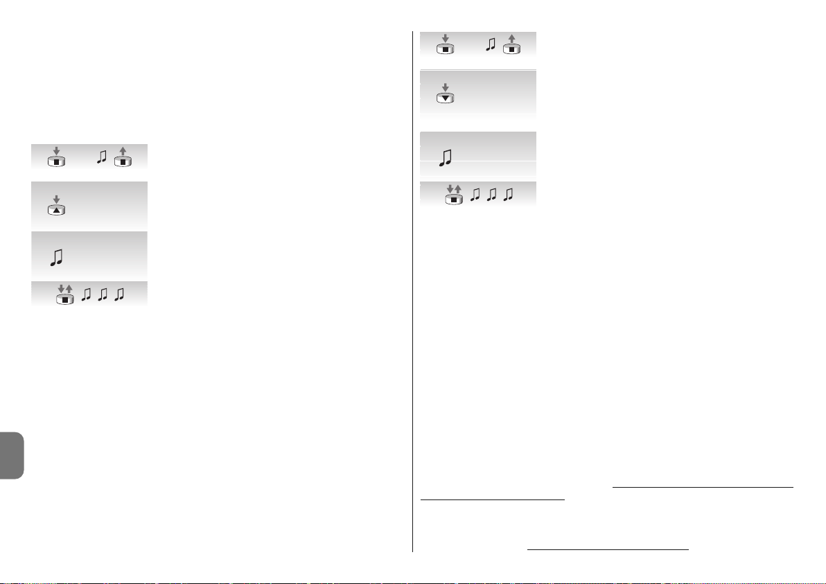
6 – Nederlands
NL
het geprogrammeerde niveau blijft. Er zijn 5 verschillende inschakelniveaus: 1=5km/h,
2=10km/h, 3=15km/h, 4=30km/h e 5=45km/h (in de fabriek is niveau 3 ingesteld).
Bij gebruik van de sensor “VOLO ST” of de radiosensoren Volo S Radio en Nemo, worden
de activeringsdrempels voor de wind rechtstreeks op de sensor geprogrammeerd (zie de
betreffende instructies).
Om het geprogrammeerde niveau te veranderen:
––––––––––––––––––––––––––––––––––––––––––––––––––––––––––––––––––––––––––––
Tabel “A9” - Wijzigen van het inschakelniveau van de windbeveiliging
––––––––––––––––––––––––––––––––––––––––––––––––––––––––––––––––––––––––––––
01. Houd toets ■ van een al in het geheugen opgeslagen
zender zo lang ingedrukt tot u (na ongeveer 5 seconden)
een geluidssignaal hoort.
02. Druk langzaam zoveel maal (1, 2, 3, 4 of 5) op toets ▲
als met het gewenste niveau overeenkomt.
03. Na enkele ogenblikken zult u een aantal geluidssignalen
horen dat met het gewenste niveau overeenkomt.
04. Druk voor bevestiging op toets ■ en laat hem los.
Als u bij punt 3 niet het aantal geluidssignalen hoort dat met het gewenste niveau overeenkomt, behoeft u geen enkele toets in te drukken en wacht u enkele seconden om te eindigen zonder het niveau te veranderen.
4.3.5 - Programmeren van het niveau van de klimaatsensor “zon”
Als er een zonsensor "VOLO S" op de ingang “sensoren” wordt aangesloten, wordt de
zonbeveiliging geactiveerd, dat wil zeggen het scherm wordt automatisch neergelaten
wanneer de zon het geprogrammeerde niveau overschrijdt. Als dat langer dan 2 minuten
het geval is, wordt er een instructie geactiveerd die overeenkomt met toets ▼; als daarna
de “zon” 15 minuten lang onder het geprogrammeerde niveau blijft wordt er een instructie
geactiveerd die overeenkomt met toets ▲.
Het is mogelijk uit 5 inschakelniveaus zon te kiezen: 1=5Klux, 2=10Klux, 3=15Klux,
4=30Klux e 5=45Klux (in de fabriek is niveau 3 ingesteld).
––––––––––––––––––––––––––––––––––––––––––––––––––––––––––––––––––––––––––––
Tabel “A10” - Wijzigen van het inschakelniveau van het zonautomatisme
––––––––––––––––––––––––––––––––––––––––––––––––––––––––––––––––––––––––––––
Bij gebruik van de sensor “VOLO ST” of de radiosensoren Volo S Radio en Nemo, worden
de activeringsdrempels voor de zon rechtstreeks op de sensor geprogrammeerd (zie de
betreffende instructies).
01. Houd toets ■ van een al in het geheugen opgeslagen
zender zo lang ingedrukt tot u (na ongeveer 5 seconden)
een geluidssignaal hoort ■ .
02. Druk langzaam zoveel maal (1, 2, 3, 4 of 5) op toets ▼
als met het gewenste niveau overeenkomt.
03. Na enkele ogenblikken zult u een aantal geluidssignalen
horen dat met het gewenste niveau overeenkomt.
04. Druk voor bevestiging op toets ■ en laat hem los.
Als u bij punt 3 niet het aantal geluidssignalen hoort dat met het gewenste niveau overeenkomt, behoeft u geen enkele toets in te drukken en wacht u enkele seconden om te eindigen zonder het niveau te veranderen.
4.3.6 - Verandering van de interventierichting in geval van regen
Als een regensensor Nemo WSRT wordt gebruikt; wanneer de sensor regen detecteert,
stuurt hij deze informatie aan de motoren en wordt er een manoeuvre in de geprogrammeerde richting aangestuurd (fabrieksinstelling: manoeuvre “omhoog”).
Om de interventierichting bij regen te veranderen:
01. Houd de toets ■ van een reeds opgeslagen zender ingedrukt tot u een pieptoon hoort
(na circa 5 seconden); laat de toets weer los.
02. Druk langzaam nog 3 maal op dezelfde toets ■ .
03. Druk op de toets voor de gewenste richting (omhoog of omlaag); op dit punt laat de
motor 3 pieptonen horen = nieuwe richting opgeslagen.
De automatische bewegingen die worden veroorzaakt door de “zon”-sensor kunnen gedeactiveerd worden door de instructie “Zon OFF” te versturen met een zender die over deze
functie beschikt (Ergo 4, Plano 4, WM004G) en kan weer opnieuw geactiveerd worden met
een instructie “Zon ON”.
De automatische bewegingen van de “zon”-sensor kunnen op elk willekeurig moment ook
gecombineerd worden met de handmatige instructies die de gebruiker met een normale
zender verstuurt; deze handmatige instructies hebben de voorrang ten opzichte van de
instructies van de “zon”-sensor, op de wijze die in het volgende voorbeeld wordt be schreven: als de zonwering in stand “1” is (automatisch bereikt als gevolg van de overschrijding van de “zon”-drempel) en de gebruiker even later de zonwering omhoog laat
komen naar de stand “0”, zal hierna, ook als het systeem de overschrijding van de “zon”drempel blijft detecteren, de zonwering niet bewogen worden
(deze blijft in de door de
5s...
5s...
x 1 = 5 Km/h
x 2 = 10 Km/h
x 3 = 15 Km/h
x 4 = 30 Km/h
x 5 = 45 Km/h
x 1 = 5 Km/h
x 2 = 10 Km/h
x 3 = 15 Km/h
x 4 = 30 Km/h
x 5 = 45 Km/h
x 1 = 5 Klux
x 2 = 10 Klux
x 3 = 15 Klux
x 4 = 30 Klux
x 5 = 45 Klux
x 1 = 5 Klux
x 2 = 10 Klux
x 3 = 15 Klux
x 4 = 30 Klux
x 5 = 45 Klux

Nederlands – 7
NL
gebruiker aangestuurde stand).
De “automatische cyclus” die werd onderbroken door de handmatige instructie wordt hervat wanneer het niveau van lichtintensiteit onder de drempel zakt (meestal is dit bij zonsondergang).
4.3.7 - Programmeren van de functie “FRT”
Nadat de standen “0” en “1” geprogrammeerd zijn kunt u desgewenst stand “2” programmeren die de functie FRT voor het aanspannen van het doek activeert.
Voor het programmeren van stand “2” volgt u de procedure uit tabel “A11”.
––––––––––––––––––––––––––––––––––––––––––––––––––––––––––––––––––––––––––––
Tabel “A11” - Programmeren van de stand “2”
––––––––––––––––––––––––––––––––––––––––––––––––––––––––––––––––––––––––––––
01. Houd toets ■ van een al in het geheugen opgeslagen
zender zo lang ingedrukt tot u (na ongeveer 5 seconden)
een geluidssignaal hoort.
02. Druk nogmaals 5 seconden op de toetsen ■▼en houd
die ingedrukt tot u 2 korte geluidssignalen hoort. Nu gaat
het scherm automatisch naar de eindpositie beneden
(stand “1”).
03. Druk binnen 5 seconden op de toetsen ▼ en ▲ om het
scherm in de stand te zetten waar u het doek wilt aanspannen.
04. Bevestig de stand binnen 5 seconden door op toets ■
van de zender te drukken tot u 3 geluidssignalen hoort.
Vervolgens gaat het scherm naar de geprogrammeerde
eindstand beneden (stand “1”).
N.B.: Als u de programmering zoals die onder punt 4 beschreven is, niet bevestigt, worden
de wijzigingen afgebroken en blijft de bestaande programmering bestaan.
Als u later na deze functie geprogrammeerd te hebben deze wilt verwijderen, dan dient u
de procedure uit tabel A13 te volgen waarbij u stap 3 overslaat, dat wil zeggen zonder
stand “1” te veranderen.
Wanneer stand “2” geprogrammeerd wordt, berekent de elektronische besturingseenheid
automatisch het verschil tussen stand “2” en stand “1”, zodat bij elke instructie voor naar
omlaag het scherm daalt tot de laagste van de standen en het doek vervolgens aanspant
tot de hoogste van de 2 standen.
4.3.8 - Programmeren van de functie “FTC”
Nadat de standen “0” en “1” geprogrammeerd zijn, is het mogelijk de stand “S” te programmeren die de functie “FTC” activeert voor het automatische beheer van schermen die
met een automatisch aanhaakmechanisme uitgerust zijn. Wil dit mechanisme correct functioneren dan dient de stand “1” enkele centimeters na het aanhaakpunt geprogrammeerd
te worden zodat bij het omhoog gaan van punt 1 het scherm aangehaakt wordt, en de
stand “S” enkele centimeters na het loshaakpunt, zodat het scherm vanaf punt “S” vrijelijk
omhoog kan gaan.
Voor het programmeren van stand “S” volgt u de procedure uit tabel “12”:
––––––––––––––––––––––––––––––––––––––––––––––––––––––––––––––––––––––––––––
Tabel “A12” - Programmeren van de Loshaakstand “S”
––––––––––––––––––––––––––––––––––––––––––––––––––––––––––––––––––––––––––––
01. Houd toets ■ van een al in het geheugen opgeslagen
zender zo lang ingedrukt tot u (na ongeveer 5 seconden)
een geluidssignaal hoort.
02. Druk nogmaals 5 seconden op de toetsen ■▼en houd
die ingedrukt tot u 2 korte geluidssignalen hoort. Nu gaat
het scherm automatisch naar de stand.
03. Druk binnen 5 seconden op de toetsen ▼ en ▲ om het
scherm in de stand “S” (kleiner dan de stand “1” te zetten waar u het scherm wilt loshaken.
04. Bevestig de stand binnen 5 seconden door op de toetsen ▼ en ▲ van de zender te drukken tot u 3 geluidssignalen hoort. Vervolgens gaat het scherm automatisch
naar de stand “0”.
N.B.: Als u de programmering zoals die onder punt 4 beschreven is, niet bevestigt, worden
de wijzigingen afgebroken en blijft de bestaande programmering bestaan.
Als u later na deze functie geprogrammeerd te hebben deze wilt verwijderen, dan dient u
de procedure uit tabel A13 te volgen waarbij u stap 3 overslaat, dat wil zeggen zonder
stand “1” te veranderen.
4.3.9 - Wijzigen van de stand “1”
Voor het verplaatsen van de stand “1” volgt u de procedure uit tabel “A13”:
––––––––––––––––––––––––––––––––––––––––––––––––––––––––––––––––––––––––––––
Tabel “A13” - Wijzigen van de stand “1”
––––––––––––––––––––––––––––––––––––––––––––––––––––––––––––––––––––––––––––
01. Houd toets ■ van een al in het geheugen opgeslagen
zender zo lang ingedrukt tot u (na ongeveer 5 seconden)
een geluidssignaal hoort.
02. Druk nogmaals 5 seconden op de toetsen ■▼en houd
die ingedrukt tot u 2 korte geluidssignalen hoort. Nu gaat
het scherm automatisch naar de stand “1”.
03. Druk binnen 5 seconden op de toetsen ▼ en ▲ om het
scherm in de nieuwe stand te zetten die u wilt programmeren.
5s...
5s...
5s...
5s...
5s...
1
S
5s...

8 – Nederlands
NL
Tabel “A15”
04. Bevestig de stand binnen 5 seconden door tegelijkertijd
op de toetsen ■ en ▼ van de zender te drukken tot u 3
geluidssignalen hoort en een korte beweging omhoog
omlaag.
N.B.: Als u de programmering zoals die onder punt 4 beschreven is, niet bevestigt, worden
de wijzigingen afgebroken en blijft de bestaande programmering bestaan.
Als u stand “1” wijzigt worden ook de functies “FRT” en “FTC” verwijderd.
4.4 - Wissen van het geheugen
Mocht het nodig zijn het geheugen van de besturingseenheid te wissen, dan kunt u de in
tabel A14 aangegeven procedure volgen.
U kunt het geheugen wissen
:
• door met een zender die niet in het geheugen is opgeslagen bij punt A te beginnen.
• door met een zender die al wel in het geheugen is opgeslagen bij punt 1 met de procedure te beginnen.
Uitgewist kunnen worden
:
• alleen de in het geheugen opgeslagen zenders, waarbij u op punt 4 stopt;
• alles (zenders, niveau van de sensoren, adres van de TTBUS …), waarbij u de procedure tot punt 6 helemaal volgt.
––––––––––––––––––––––––––––––––––––––––––––––––––––––––––––––––––––––––––––
Tabel “A14” - Wissen van het geheugen
––––––––––––––––––––––––––––––––––––––––––––––––––––––––––––––––––––––––––––
A. Terwijl de motor niet onder spanning staat activeert u de
ingang Stap-voor-Stap (verbind de draad Wit met Wit/
Zwart) en houd die geactiveerd tot na afloop van de procedure.
B. Sluit de motor op de stroomvoorziening via het elektrici-
teitsnet aan en wacht op de geluidssignalen van het begin.
01. Druk op toets ■ van een zender en houd die (circa 5
seconden) ingedrukt tot u een geluidssignaal hoort; laat
daarna toets ■ .
02. Houd de toets ▲ van de zender ingedrukt tot u 3 ge -
luidssignalen hoort; laat de toets ▲ precies tijdens het
derde geluidssignaal los.
03. Houd toets ■ van de zender ingedrukt tot u 3 geluidssignalen hoort; laat toets ■ precies tijdens het derde ge luidssignaal los.
04. Houd de toets ▼ van de zender ingedrukt tot u 3 ge -
luidssignalen hoort; laat de toets ‚ precies tijdens het
der de geluidssignaal los.
05. Om alles te wissen: druk binnen 2 seconden op beide
toetsen ▲ en ▼.
06. Raat de toetsen ▲ en ▼ los wanneer u het eerste van de
5 geluidssignalen hoort die de annulering bevestigen.
De motoren uit de serie NEOMAT-T herkennen de zenders uit de serie ERGO, PLANO,
NICEWAY, VOLO S RADIO en NEMO, (zie hoofdstuk 5.1 “Bruikbare zenders”).
Bovendien kunt u met speciale procedures voor geheugenopslag aan elke toets van de
zender een bepaalde instructie koppelen (zie hoofdstuk 5.2 “Programmeren van zenders in
Modus I en Modus II”).
Let op!: gebruik voor het programmeren alleen zenders die in Modus I in het geheugen zijn opgeslagen.
5.1 - Bruikbare zenders
In tabel A15 zijn de zenders aangegeven die gebruikt kunnen worden met de bijbehorende
type codering
5
Nadere details
P. P.
5s...

Nederlands – 9
NL
––––––––––––––––––––––––––––––––––––––––––––––––––––––––––––––––––––––––––––
Tabel “A15” - Zenders
• ERGO1 - ERGO4 - ERGO6 • PLANO1 - PLANO4 - PLANO6 - PLANO TIME • VOLO S
RADIO • NEMO • NICEWAY (de gehele lijn) • FLO1R - FLO2R - FLO4R • VERY VR •
––––––––––––––––––––––––––––––––––––––––––––––––––––––––––––––––––––––––––––
5.2 - Geheugenopslag van de zenders in Modus I en Modus II
In de tabellen “A1” en “A2” wordt de geheugenopslag van de zenders in Modus I beschreven, waar aan elke toets een bepaalde instructie is toegekend: toets ▲ (1) = “Omhoog”;
toets ■ (2) = “Stop”; toets ▼ (3) = “Omlaag”.
De zenders kunnen ook in Modus II worden opgeslagen; deze modus biedt u een maximum aan flexibiliteit bij het gebruik van de toetsen van de zenders. In dezelfde motor NEOMAT-T kunt u zenders zowel in Modus I als in Modus II in het geheugen opslaan.
5.2.1 - Modus I
In Modus I is de bedieningsopdracht vast gekoppeld aan de toetsen van de zender: toets
▲ (1) stuurt de manoeuvre “Omhoog” aan; toets ■ (2) geeft de instructie “Stop”; de toets ‚
(3) voor de instructie “Omlaag”, een eventuele toets ▼ geeft de instructie “Stop”. In Modus
I wordt er voor elke zender slechts één enkele fase van geheugenopslag uitgevoerd en
wordt er slechts één plaats in het geheugen in beslag genomen. Bij geheugenopslag in
Modus I is het niet van belang op welke toets u drukt. Voor het in het geheugen opslaan of
wissen van de zenders in Modus I gelieve u de tabellen A1 en A2 te raadplegen.
Toets Instructie
To et s ▲ of 1 Omhoog
To et s ■ of 2 Stop
To et s ▼ of 3 Omlaag
Toets 4 Stop
5.2.2 - Modo II
In Modus II kunt u aan elke toets van de zender één van de 4 mogelijke instructies koppelen: 1 = Stap-voor-Stap; 2 = Omhoog-Stop; 3 = Omlaag-Stop, 4 = Stop.
In Modus II voert u voor elke toets een procedure voor geheugenopslag uit en elke toets
neemt een plaats in het geheugen in beslag. Bij geheugenopslag in Modus II wordt de
ingedrukte toets in het geheugen opgeslagen. Mocht u aan nog een toets van dezelfde
zender nog een instructie willen toekennen, dan dient u een nieuwe procedure voor geheugenopslag uit te voeren.
Nr. Instructie
1 Stap-voor-Stap” (omhoog-stop-omlaag-stop…),
2 Omhoog-Stop (omhoog-stop-omhoog-stop…)
3 Omlaag-Stop (omlaag-stop-omlaag-stop…)
4 Stop
5.2.3 - Voorbeeld van gemengde geheugenopslag in Modus I en Modus II
Door Modus I en Modus II van geheugenopslag te benutten is het mogelijk instructies voor
groepen aan te maken zoals u op het voorbeeld op de afb. A kunt zien.
• De zender T1 (Ergo1) opgeslagen in Modus I op A1 en A2 tegelijkertijd de manoeuvre
omhoog, de stop of omlaag van zowel A1 als A2 aan.
• De zender T2 (Plano1) opgeslagen in Modus I alleen op A3 stuurt alleen op A3 stuurt de
manoeuvre omhoog, stop of de manoeuvre alleen van A3 aan.
• De zender T3 (Planotime) opgeslagen in Modus I alleen op A4 stuurt de manoeuvre
omhoog, de stop of de manoeuvre omlaag alleen van A4 aan.
• De zender T4 (WM001C) opgeslagen in Modus II (Stap-voor-Stap) stuurt alleen A4 aan.
• De zender T5 (WM003G) opgeslagen in Modus I om met groep 1 op A1 en A2, met
groep 2 op A3 en met groep 3 op A4 aan te sturen; stuurt de manoeuvre omhoog, de
stop of de manoeuvre omlaag van A1 en A2, A3 of A4 aan.
• De zender T6 (Flo4R) opgeslagen in Modus II op A4 (toetsen 1 en 3) op A5 (toets 2) en
op A6 (toets 4) stuurt de manoeuvre omhoog en omlaag van A4 aan, of de opening van
de garagedeur A5 of de opening van de automatische poort A6.
LET OP !:
• Met een zender die in Modus II in het geheugen is opgeslagen, is het niet mogelijk sommige functies (richting van beweging, bedrijfsduur…) te programmeren, als hiervoor het
nodig is verschillende toetsen in te drukken, zoals bij voorbeeld toets ■ en de toets ▲.
• Met een zender die in Modus II in het geheugen is opgeslagen kunnen de instructies
voor een “meervoudige groep” niet gebruikt worden.
Wanneer er al één of meerdere zenders in het geheugen zijn opgeslagen kunt u andere in
Modus II volgens de aanwijzingen van tabel A16 programmeren.
––––––––––––––––––––––––––––––––––––––––––––––––––––––––––––––––––––––––––––
Tabel “A16” - Geheugenopslag van andere zenders in Modus II
––––––––––––––––––––––––––––––––––––––––––––––––––––––––––––––––––––––––––––
01. Druk op die toets van de zender welke opgeslagen moet
worden en houd die ingedrukt (ongeveer 5 seconden) totdat u een geluidssignaal hoort; laat daarna de toets los.
02. Druk binnen 5 seconden op de toets van een oude en al
geprogrammeerde zenden en houd die ingedrukt (ongeveerd 5 seconden) tot u 2 geluidssignalen hoort en laat
daarna de toets los.
03. Begin binnen 5 seconden zoveel maal op diezelfde toets
van de zender te drukken als voor de.
gewenste bedieningsopdracht nodig is: 1 = “Stap-voorStap” 2 = “omhoog” 3 = “omlaag” 4 = “stop”.
04. Na ongeveer 3 seconden zult u zoveel geluidssignalen
horen als gelijk is aan het getal van de geselecteerde
instructie.
5s.
nieuw
5s.
oud
1- 4
nieuw
1- 43s.
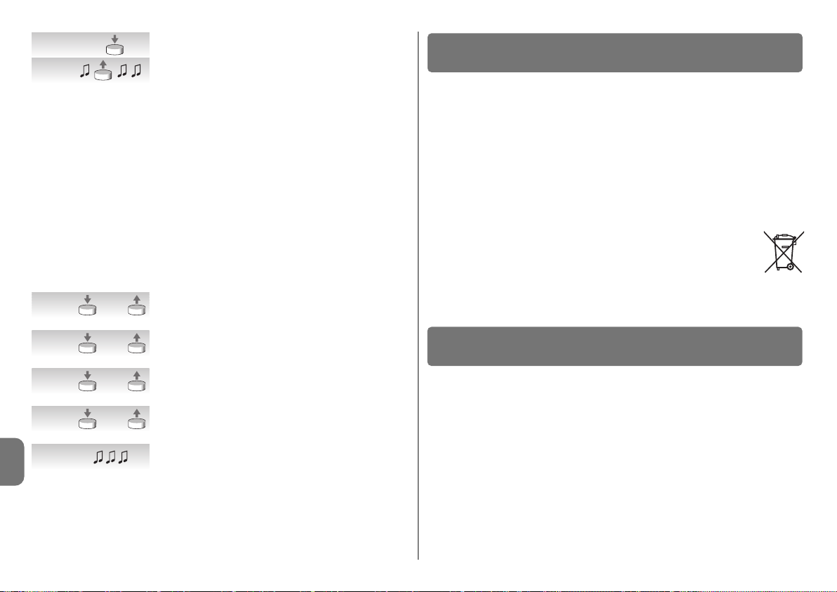
10 – Nederlands
NL
05. Druk binnen 2 seconden op dezelfde toets van de nieu-
we zender.
06. Laat de toets los bij het eerste van de 3 geluidssignalen
die de programmering bevestigen.
Als u op punt 5 niet het aantal geluidssignalen hoort dat overeenkomt met de gewenste
instructie, behoeft u op geen enkele toets te drukken en wacht u enkele seconden totdat
de programmeerfase beëindigd wordt zonder dat er iets in het geheugen is opgeslagen.
N.B.: als het geheugen vol is (14 zenders) zult u 6 geluidssignalen horen en de zender zal
niet geprogrammeerd kunnen worden.
Er bestaat een eenvoudige manier om een nieuwe zender in het geheugen op te slaan
waarbij de kenmerken van de oude zender behouden blijven; u volgt hiervoor de procedure van tabel A17. De op die manier in het geheugen opgeslagen nieuwe zender zal de kenmerken van de oude erven, dat wil zeggen, als de oude in Modus I in het geheugen was
opgeslagen, dan zal ook de nieuwe in Modus I functioneren; als de oude in Modus II in het
geheugen was opgeslagen, dan zal ook de toets van de nieuwe zender aan dezelfde
bedieningsopdracht van de oude gekoppeld worden.
––––––––––––––––––––––––––––––––––––––––––––––––––––––––––––––––––––––––––––
Tabel “A17” - Geheugenopslag van andere zenders
––––––––––––––––––––––––––––––––––––––––––––––––––––––––––––––––––––––––––––
01. Druk op de in het geheugen te bewaren toets van de
nieuwe zender, houd die tenminste 3 seconden vast en
laat daarna de toets los.
02. Druk op de al opgeslagen toets van de oude zender,
houd die tenminste 3 seconden vast en laat daarna de
toets los.
03. Druk op de reeds opgeslagen toets van de nieuwe zender, houd die tenminste 3 seconden vast en laat daarna
de toets los.
04. Druk op de reeds opgeslagen toets van de oude zender,
houd die tenminste 3 seconden vast en laat daarna de
toets los.
05. U zult nu 3 geluidssignalen horen ter bevestiging van de
programmering van de nieuwe zender.
N.B.: als het geheugen vol is (14 zenders) zult u 6 geluidssignalen horen en de zender zal
niet geprogrammeerd kunnen worden.
Dit product is integrerend deel van de automatisering die het aanstuurt en moet dus
samen daarmee worden naar de afvalverwerking gestuurd.
Wanneer de levensduur van dit product ten einde is, dienen, zoals dit ook bij de installatiewerkzaamheden het geval is, de ontmantelingswerkzaamheden door gekwalificeerde
technici te worden uitgevoerd.
Dit product bestaat uit verschillende soorten materialen: sommige daarvan kunnen
opnieuw gebruikt worden, terwijl andere als afval verwerkt dienen te worden. Win inlichtingen in over de methoden van hergebruik of afvalverwerking in en houd u aan de plaatselijk
voor dit soort producten van kracht zijnde voorschriften.
Let op! – sommige onderdelen van het product kunnen vervuilende of gevaarlijke stoffen
bevatten: indien die in het milieu zouden verdwijnen, zouden ze schadelijke gevolgen voor
het milieu en de menselijke gezondheid kunnen opleveren.
Zoals dat door het symbool hiernaast is aangegeven, is het verboden dit product met het gewone huisafval weg te gooien. Scheid uw afval voor verwerking op een manier zoals die in de plaatselijke regelgeving is voorzien of lever
het product bij uw leverancier in, wanneer u een nieuw gelijksoortig product
koopt.
Let op! – de plaatselijke regelgeving kan in zware straffen voorzien in geval van illegale
dumping van dit product.
❏ Nadat de motor onder spanning is gebracht geeft de motor geen enkel
geluidssignaal en de ingang stap-voor-stap activeert geen enkele manoeuvre.
Controleer of de stroomtoevoer van de motor de juiste netspanning heeft; indien de
stroomtoevoer in orde is, zal er waarschijnlijk sprake zijn van een ernstig defect en moet de
motor door het technisch servicecentrum gerepareerd worden.
❏ Na een instructie zet de motor zich niet in beweging.
• Als de motor tot even daarvoor werkte, zou het kunnen zijn dat de motorbeveiliging in
werking is getreden; wacht eventjes tot de motor is afgekoeld.
• Controleer of de ingang “stap-voor-stap” werkt door de draden Wit en Zwart-wit met
elkaar te verbinden.
• Controleer dat er tenminste één zender in het geheugen is opgeslagen door na te gaan
of bij het aanzetten van de motor er korte geluidssignalen klinken.
• Ga na dat de zender en motor met elkaar “communiceren” door de toets ■ (2) van een
zender (al dan niet geprogrammeerd) tenminste 5 seconden ingedrukt te houden; als u
een geluidssignaal hoort betekent dit dat de motor het signaal van de zender ontvangt;
7
Wat te doen als... ofwel een kleine gids als er iets niet functioneert!
6
Afvalverwerking van het product
>3s.
nieuw
>3s.
oud
>3s.
nieuw
>3s.
oud
nieuw

Nederlands – 11
NL
Technische gegevens buismotoren NEOMAT-MT en NEOMAT-LT
• Spanning en frequentie stroomvoorziening: zie de technische gegevens op het etiket
van de afzonderlijke modellen
• Stroom en vermogen: zie de technische gegevens op het etiket van de afzonderlijke
modellen
• Koppel en snelheid: zie de technische gegevens op het etiket van de afzonderlijke
modellen
• Diameter van de motor: NEOMAT-MT = 45mm; NEOMAT-LT = 58mm
• Precisie (resolutie) van de elektronische eindschakelaar: meer dan 0,55° (afhankelijk
van de uitvoering van NEOMAT-T)
• Precisie van de posities van de stops van de eindschakelaars: Klasse 2 (± 5%)
• Mechanische weerstand: volgens EN 14202
• Nominale werkingsduur: Maximaal 4 minuten
• Beschermingsklasse: IP 44
• Werkingstemperatuur: -20 ÷ +55 °C
• Lengte aansluitkabel: 3 m
• Spanning signalen (stap-voor-stap, TTBUS…): ongeveer 24 V
• Niveaus windsensor (anemometer): 5 t.w. ongeveer 5, 10, 15, 30 of 45 km/h (bij de
anemometers VOLO of VOLOS)
• Niveaus zonsensor: 5 t.w. ongeveer 5, 10, 15, 30 of 45 Klux (bij VOLOS )
• Lengte kabel signalen (Stap-voor-Stap, TTBUS....): ten hoogste 30m indien in de
nabijheid van andere kabels, anders 100m
• Frequentie radio-ontvanger: 433,92 MHz
• Codering radio-ontvanger: 52 bits rolling code FLOR en FLOR+INFO
• Aantal zenders dat opgeslagen kan worden: 14, met inbegrip van ten hoogste 3 kli-
maatsensoren VOLO-S-Radio
• Bereik van de zenders: geschat op 150 m in de vrije ruimte en 20 m binnenshuis (*)
Opmerkingen:
– (*) Het bereik van de zenders kan worden beïnvloed door andere inrichtingen die in de
omgeving daarvan op dezelfde frequentie werken als de zender (bijvoorbeeld koptelefoons, alarmsystemen e.d.) waardoor er interferentie met de ontvanger ontstaat. In geval
van sterke interferentie kan Nice ten aanzien van het daadwerkelijke bereik van haar
radio-grafische inrichtingen geen enkele zekerheid bieden.
- Alle technische gegevens hebben betrekking op een omgevingstemperatuur van 20°C
(±5°C).
- Nice S.p.a. behoudt zich het recht voor op elk gewenst moment en zonder voorbericht
wijzigingen in haar producten aan te brengen, waarbij gebruiksbestemming en functionaliteit echter gehandhaafd blijven.
ga dan door met de laatste controle; doe anders de volgende controle.
• Controleer met de volgende empirische test of de zender correct een radiosignaal uitzendt: druk op een toets en laat het ledlampje op de antenne van een normaal radiotoestel (het liefst een goedkoop toestel) dat aan staat en afgestemd is op de FM-band op
de frequentie 108,5Mhz of zo dicht mogelijk daarbij; u zou u een licht krakerig geluid
moeten horen.
• Controleer door langzaam één voor één op elke toets van de zender te drukken; als er
geen enkele toets is die een manoeuvre van de motor aanstuurt, betekent dit dat die
zender niet in het geheugen is opgeslagen.
❏ Na een radio-instructie hoort u 6 geluidssignalen en gaat er geen ma noeuvre van start.
De radio-instructie is niet gesynchroniseerd; u dient de zender opnieuw in het geheugen
op te slaan.
❏ Na een instructie hoort u 10 geluidssignalen, daarna gaat er een manoeuvre van start.
Zelfdiagnose van de parameters in het geheugen heeft aangegeven dat er een anomalie is
(standen, TTBUS-adres of windniveau zijn fout), wis het geheugen en probeer opnieuw te
programmeren.
❏ Bij het omhoog gaan stopt de motor voordat de geplande stand bereikt
wordt (stand “0”, stand “I”) en daarna hoort u dat de motor 3 maal probeert
opnieuw van start te gaan.
Dit kan normaal zijn: bij het omhoog gaan zal de motor wanneer er een te grote belasting
wordt geconstateerd, 1 seconde stoppen; vervolgens probeert de motor de manoeuvre
ten einde te brengen. Controleer of er geen obstakels zijn die de manoeuvre beletten.
❏ Bij het naar omlaag gaan, stopt de motor voordat de geplande stand
(stand “1”, stand “I”) bereikt wordt.
Dit kan normaal zijn: bij het uitrollen zal de motor wanneer er een te grote belasting wordt
geconstateerd uit gaan. Controleer of er geen obstakels zijn die de manoeuvre beletten.
❏ De motor beweegt alleen in de modus “iemand aanwezig.
Als de standen “0” en “1” niet geprogrammeerd zijn vindt de manoeuvre omhoog en
omlaag alleen plaats in de modus iemand aanwezig. Programmeer de standen “0” en “1”.
❏ De motor beweegt correct omhoog maar bij “persoon aanwezig” omlaag.
Zelfdiagnose van de parameters in het geheugen heeft aangegeven dat er een anomalie is
in de stand van de motor. Laat de zonwering met een handmatige instructie volledig
omhoog gaan.
12 – Nederlands
NL
EG-VERKLARING VAN OVEREENSTEMMING
Opmerking - De inhoud van deze verklaring stemt overeen met hetgeen verklaard is in de laatste revisie die beschikbaar was voor het ter perse gaan van deze handleiding, van het officiële document dat is neergelegd bij de vestiging
van Nice Spa. Deze tekst werd om uitgeversredenen heraangepast.
Nummer: 223/Neomat T Revisie: 3
Ondergetekende Luigi Paro, in de hoedanigheid van Gedelegeerd Bestuurder, verklaart onder zijn eigen verantwoordelijkheid dat het product:
Naam fabrikant: NICE s.p.a.
Adres: Via Pezza Alta, 13, Z.I. Rustignè, 31046 - Oderzo (TV) Italië
Type: Buisreductiemotor voor zonwering in kast met ingebouwde besturingseenheid en radio-ontvanger
Modellen: Neomat MT, Neomat LT
Accessoires: Radiobedieningen serie Ergo, Plano, NiceWay, VOLO-S-Radio Luchtsnelheidsmeters VOLO, VOLO-S
conform is aan hetgeen is voorzien in de volgende communautaire richtlijn:
• 1999/5/EG RICHTLIJN 1999/5/EG VAN HET EUROPEES PARLEMENT EN VAN DE RAAD van 9 maart 1999, met
betrekking tot radioapparatuur en eindapparatuur voor telecommunicatie en de wederzijdse erkenning van hun
conformiteit, volgens de volgende geharmoniseerde normen:
- Bescherming van de gezondheid: EN 50371:2002
- Elektromagnetische compatibiliteit: EN 301 489-1 V1.8.1:2008; EN 301 489-3 V1.4.1:2002
- Elektrische veiligheid: EN 60950-1:2006
- Radiospectrum: EN 300 220-2 V2.1.2:2007
Bovendien is het product conform aan hetgeen voorzien is in de volgende communautaire richtlijnen, zoals gewijzigd
bij de Richtlijn 93/68/EEG van de Raad van 22 juli 1993:
• 2006/95/EG RICHTLIJN 2006/95/EG VAN HET EUROPESE PARLEMENT EN DE RAAD van 12 december 2006
met betrekking tot de onderlinge aanpassing van de wetgevingen van de Lidstaten met betrekking tot elektrisch
materiaal dat bestemd is om binnen bepaalde spanningslimieten gebruikt te worden, volgens de volgende geharmoniseerde normen: EN 60335-1:2002 + A1:2004 + A11:2004 + A12:2006 + A2:2006 + A13:2008; EN 60335-297:2006 + A11:2008; EN50366:2003 + A1:2006
• 2004/108/EEG RICHTLIJN 2004/108/EG VAN HET EUROPESE PARLEMENT EN DE RAAD van 15 december
2004 met betrekking tot de onderlinge aanpassing van de wetgevingen van de Lidstaten met betrekking tot de
elektromagnetische compatibiliteit waarmee de richtlijn 89/336/EEG wordt afgeschaft, volgens de volgende normen: EN 55014-1:2006; EN 55014-2:1997 + A1:2001; EN 61000-3-2:2006; EN 61000-3-3:2007
Oderzo, 28 juli 2009
Luigi Paro
(Gedelegeerd Bestuurder)


NL PL DE ES FR IT EN
EN - Images
IT - Immagini
FR - Images
ES - Imágenes
DE - Bilder
PL - Zdjęcia
NL - Afbeeldingen
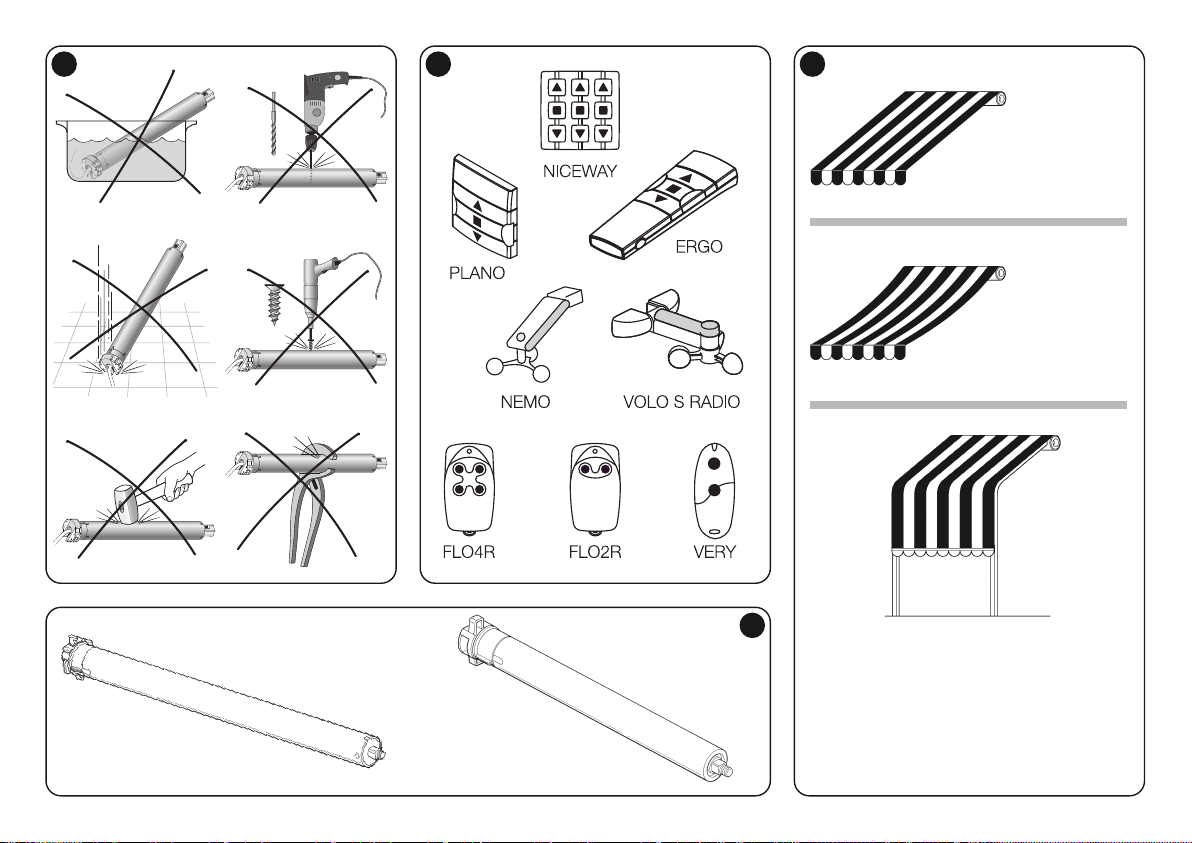
NEOMAT-MT NEOMAT-LT
• Without FRT
• Con FRT
• Sans FRT
• Sin FRT
• ohne FRT
• bez FRT
• Zonder FRT
• With FRT
• Senza FRT
• Avec FRT
• Con FRT
• mit FRT
• z FRT
• Met FRT
• Arbour awning with hooks
• Tenda a capanno con ganci
•
Store à montants latéraux courbes avec crochets
•
Toldo veranda con ganchos
•
Beschattungs- mit Senkrechtmarkise mit Haken
•
Markiza w formie daszku z zaczepami
• Zonnescherm met luifel voorzien van haken
1 3
A
2

D
E
A
B
F
C
A
B
C
F
D
E
4 5

L
N
• Violet label
• Etichetta viola
• Étiquette violette
• Etiqueta violeta
• Violettes Etikett
• Etykietka fioletowa
• Paars etiket
• Yellow label
• Etichetta gialla
• Étiquette jaune
• Etiqueta amarilla
• Gelbes Etikett
• Etykietka żółta
• Geel etiket
Wire colouring:
Mains power supply
Brown = Phase
Blue = Neutral
Yellow/Green = Earth
–––––––––––––––––––––––––––––––––––
Colorazione conduttori:
Alimentazione da rete
Marrone = Fase
Blu = Neutro
Giallo/Verde = Terra
–––––––––––––––––––––––––––––––––––
Couleurs des conducteurs
Alimentation du secteur
Brun = Phase
Bleu = Neutre
Jaune/vert = Terre
–––––––––––––––––––––––––––––––––––
Color de los conductores:
Alimentación de red
Marrón = Fase
Azul = Neutro
Amarillo/Verde = Tierra
Farbe der Leiter
Netzstromversorgung
braun = Phase
blau = Nullleiter
gelb/grün = Erde
–––––––––––––––––––––––––––––––––––
Kolory ży
ł
Zasilenie z sieci
Brązowy = Faza
Niebieski = Neutralny
Ż
ółto/Zielony = Uziemienie
–––––––––––––––––––––––––––––––––––
Kleur draden:
Stroomvoorziening van het
elektriciteitsnet
Bruin = Fase
Blauw = Nulleider
Groen/Geel = Aarde
Command signals
Black/White = Common (0V)
White = Step-by-St. + “TTBUS” / F210S
Orange/White = Weather sensors
–––––––––––––––––––––––––––––––––––
Segnali di comando
Nero/Bianco = Comune (0V)
Bianco = Passo-P. + “TTBUS” / F210S
Arancio/Bianco = Sensori climatici
–––––––––––––––––––––––––––––––––––
Signaux de commande
Noir/Blanc = Commun (0 V)
Blanc = pas à pas + TTBUS / F210S
Orange/blanc = capteurs climatiques
–––––––––––––––––––––––––––––––––––
Señales de mando
Negro/Blanco = Común (0V)
Blanco = Paso-P. + TTBUS / F210S
Naranja/Blanco = Sensores climáticos
Steuersignale
Schwarz-Weiß = Gemeinsamer Leiter (0V)
Weiß = Schrittbetr. + TTBUS / F210S
Orange/Weiß = Wetterwächter
–––––––––––––––––––––––––––––––––––
Sygnały sterujące
Czarno/Białe = Wspólny (0V)
Biały = Krok po Kroku + TTBUS /
F210S
Pomarańczowo/Biały = czujniki
klimatyczne
–––––––––––––––––––––––––––––––––––
Bedieningssignalen
Zwart-wit = Nulleider (0V)
Wit = Stap voor stap + TTBUS / F210S
Oranje-wit = Klimaatsensoren
6
B

a b c d
C
F
D


Nice South Africa
Johannesburg South Africa
info@co.za.niceforyou.com
Nice Polska
Pruszków Polska
Ph. +48.(022).759.40.00
Fax +48.(022).759.40.22
info@pl.niceforyou.com
Nice Portugal
Mem Martins Portugal
Ph. +351.21.922.82.10
Fax +351.21.922.82.19
info@pt.niceforyou.com
Nice Romania
Cluj Napoca Romania
Ph./Fax +40.(0)264.453.127
info@ro.niceforyou.com
Nice Turkey
Kadikoy Istanbul Turkey
Ph. +90.216.456.34.97
Fax +90.216.455.78.29
info@tr.niceforyou.com
Nice UK
Sutton in Ashfield
United Kingdom
Ph. +44.16.23.55.80.86
Fax +44.16.23.55.05.49
info@uk.niceforyou.com
www.niceforyou.com
Headquarters
Nice SpA
Oderzo TV Italia
Ph. +39.0422.85.38.38
Fax +39.0422.85.35.85
info@niceforyou.com
Nice in Italy
Nice Padova
Padova Italia
Ph. +39.049.87.01.05.1
Fax +39.049.87.07.63.8
infopd@niceforyou.com
Nice Roma
Roma Italia
Ph. +39.06.72.67.17.61
Fax +39.06.72.67.55.20
inforoma@niceforyou.com
Nice Worldwide
Nice France
Buchelay France
Ph. +33.(0)1.30.33.95.95
Fax +33.(0)1.30.33.95.96
info@fr.niceforyou.com
Nice France Sud
Aubagne France
Ph. +33.(0)4.42.62.42.52
Fax. +33.(0)4.42.62.42.50
infomarseille@fr.niceforyou.com
Nice France Rhône Alpes
Decines Charpieu France
Ph. +33.(0)4.78.26.56.53
Fax +33.(0)4.78.26.57.53
infolyon@fr.niceforyou.com
Nice Belgium
Leuven (Heverlee) Belgium
Ph. +32.(0)16.38.69.00
Fax +32.(0)16.38.69.01
info@be.niceforyou.com
Nice Deutschland
Gelnhausen Deutschland
Ph. +49.(0)6051.91.520
Fax +49.(0)6051.91.52.119
info@de.niceforyou.com
Nice España Madrid
Mostoles Madrid España
Ph. +34.(0)9.16.16.33.00
Fax +34.(0)9.16.16.30.10
info@es.niceforyou.com
Nice España Barcelona
Sant Quirze del Valles
Barcelona España
Ph. +34.(0)9.37.84.77.75
Fax +34.(0)9.37.84.77.72
info@es.niceforyou.com
Nice Australia
Wetherill Park Australia
Ph. +61.(0)2.96.04.25.70
Fax +61.(0)2.96.04.25.73
info@au.niceforyou.com
Nice China
Shanghai P. R. China
Ph. +86.21.575.701.46
Fax +86.21.575.701.44
info@niceforyou.com.cn
Nice USA
San Antonio Texas USA
info@us.niceforyou.com
Nice Russia
Odintsovo Moscow Region Russia
Ph. +7.495.739.97.02
Fax +7.495.739.97.02
info@ru.niceforyou.com
89.053R01 – Rev. 00 – 12-11-2009
 Loading...