


neomat A
tubular motor
Instrukcje i uwagi dla instalatora
Istruzioni ed avvertenze per l’installatore
Instructions and warnings for the fitter
Instructions et recommandations pour l’installateur
Anweisungen und Hinweise für den Installateur
Instrucciones y advertencias para el instalador

2
Warnings:
The “NEOMAT A” series motors have been designed for the automation
of roller shutters; any other use is considered improper and is prohibited.
These motors are intended for residential use. Maximum continuous operating time is 4 minutes with a 20% cycle. When selecting the type of motor
based on the application, you should consider the nominal torque and the
operating time shown on the rating plate. The minimum diameter of the
tube in which the motor can be installed is 40 mm for NEOMAT SA and
70 mm for NOEMAT LA. The motor must be installed by qualified personnel in compliance with current safety regulations. As regards units for outdoor use, the PVC power supply cable must be installed inside a protective duct.
The tubular motor must not be subjected to crushing, impacts, falls or
contact with any kind of liquid. Do not perforate or drive screws into any
part of the tubular motor (fig. 1). For maintenance and repairs contact a
qualified technician.
Warning: some programming phases may use the mechanical stops on
the rolling shutter (rubber stops and/or anti-burglar latches). In such cases, the motor with the most suitable torque for a given application must be
chosen, taking into consideration the effective weight of the rolling shutter
in order to avoid choosing too powerful motors.
The NEOMAT SA Ø35mm, NEOMAT MA Ø45mm (fig. 2) and NEOMAT LA Ø58mm tubular motors feature an electronic control unit
with incorporated radio receiver, operating at a frequency of 433.92
MHz, with rolling code technology, to guarantee high levels of security. Up to 14 “ERGO” and “PLANO” or “VOLO S RADIO” series radio
controls (fig. 3 and 4) can be memorised for each motor.
The control unit incorporated in the motor features a high precision
electronic limit switch system capable of continuously monitoring the
position of the shutter. The range of movement, i.e. the closed/open
positions (plus any intermediate positions) can be programmed and
memorised; after each command, the movement stops automatically when these positions are reached.
The control unit will also reveal any sharp variations and excessive
strain on the motor, and quickly block the movement. This feature is
also used to automatically programme the manoeuvring limits if the
rolling shutter has upper limit switch rubber stops and anti-burglar
latches.
The range of movement and a few additional functions can be programmed through the radio controls. A beep will sound to guide the
various phases. The motors can also be controlled through an external button (with step-by-step function) or a Bus (“TTBUS”). Optional
wind, sun and rain sensors can activate the system automatically
whenever the weather conditions demand it.
1) Product description
2) Installation
Proceed as follows to prepare the motor (fig. 4):
1. Position the idle ring nut (E) on the motor (A) until it fits into the
corresponding idle ring (F).
2. Mount the draw ring nut (D) on the motor shaft. On NEOMAT SA
the ring nut snaps on automatically.
3. On NEOMAT MA, fasten the draw ring nut with the snap ring.
Figure 4
A: NEOMAT tubular motor
B: Fastening clips or split pins
C: Support and spacer
D: Draw ring nut
E: Idle ring nut
F: Idle ring
NEOMAT A is produced by Motus S.p.a. (TV) I. ERGO, PLANO, VOLO are produced by Nice S.p.a. (TV) I. Motus S.p.a. is an affiliate of the Nice S.p.a. group
Fit the assembled motor into the shutter’s winding tube until it touches the end of the idle ring nut (E). Fasten the tube to the draw ring
nut (D) using the M4x10 screw in order to prevent the motor from
slipping or sliding axially (fig. 5). Finally, secure the motor head to the
special support (C) with the spacer (if any), using the clips or split pin
(B).
2.1) Electrical connections
WARNING: For motor connections, an omnipolar disconnecting device with a 3-mm minimum distance
between contacts must be provided for disconnection
from the mains power supply (disconnecting switch or
plug and socket, etc.).
WARNING: carefully follow all the connection instructions. If you have any doubts do not make experiments but
consult the relevant technical specifications sheets which
are also available on the web site "www.niceforyou.com".
An incorrect connection may be dangerous and cause
damage to the system.
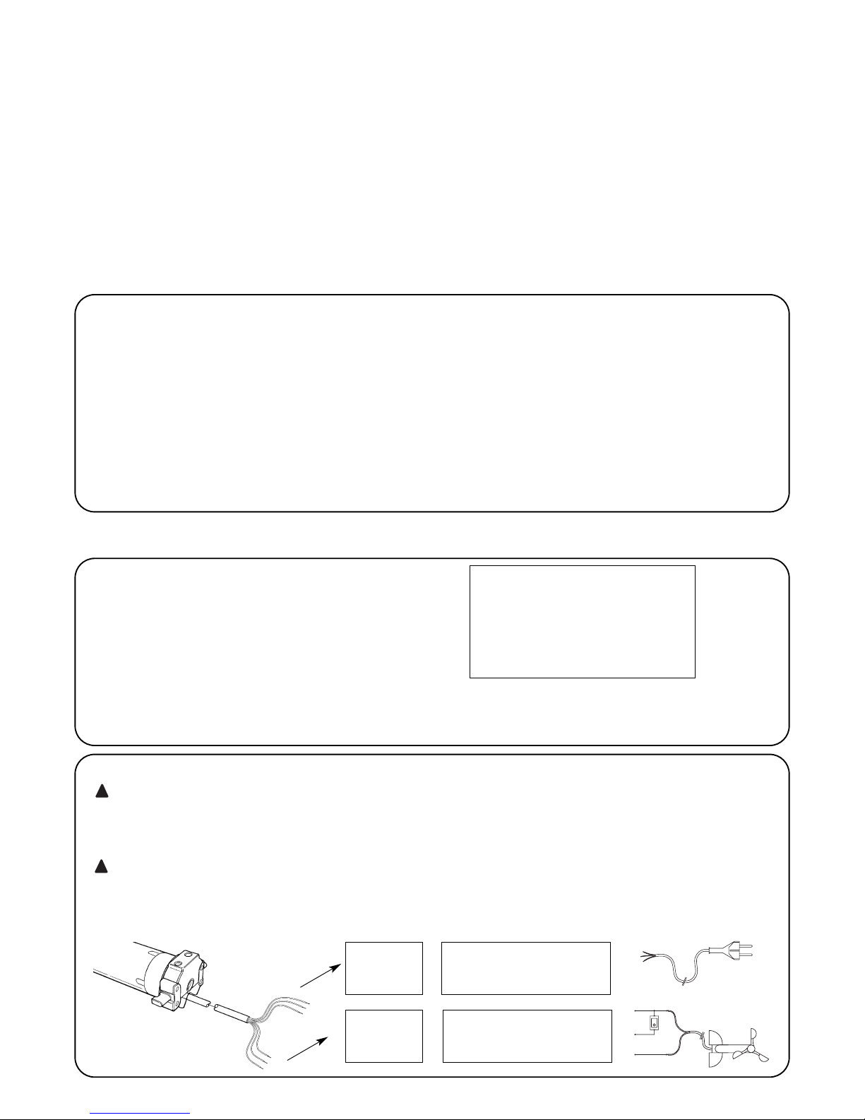
The cable used for the electrical connections of the NEOMAT A
motor has 6 wires:
•Supply line from the power mains: Phase, Neutral and Earth
• Extra low voltage control signals (SELV): Step-by-step or
“TTBUS” Bus and weather sensors
!
!
Brown = Phase
Blue = Neutral
Yellow/Green = Earth
Black = Common (0V)
White =
Step-by-Step + “TTBUS”
Orange = Weather sensorsi
Yellow label
Green label
GB
3
2.2) Connector and power supply cable (this section refers only to the NEOMAT A version and concerns customer service per-
sonnel only)
WARNING: if the power cord is damaged it must be replaced with an identical type supplied by the manufacturer or
an authorised customer service centre.
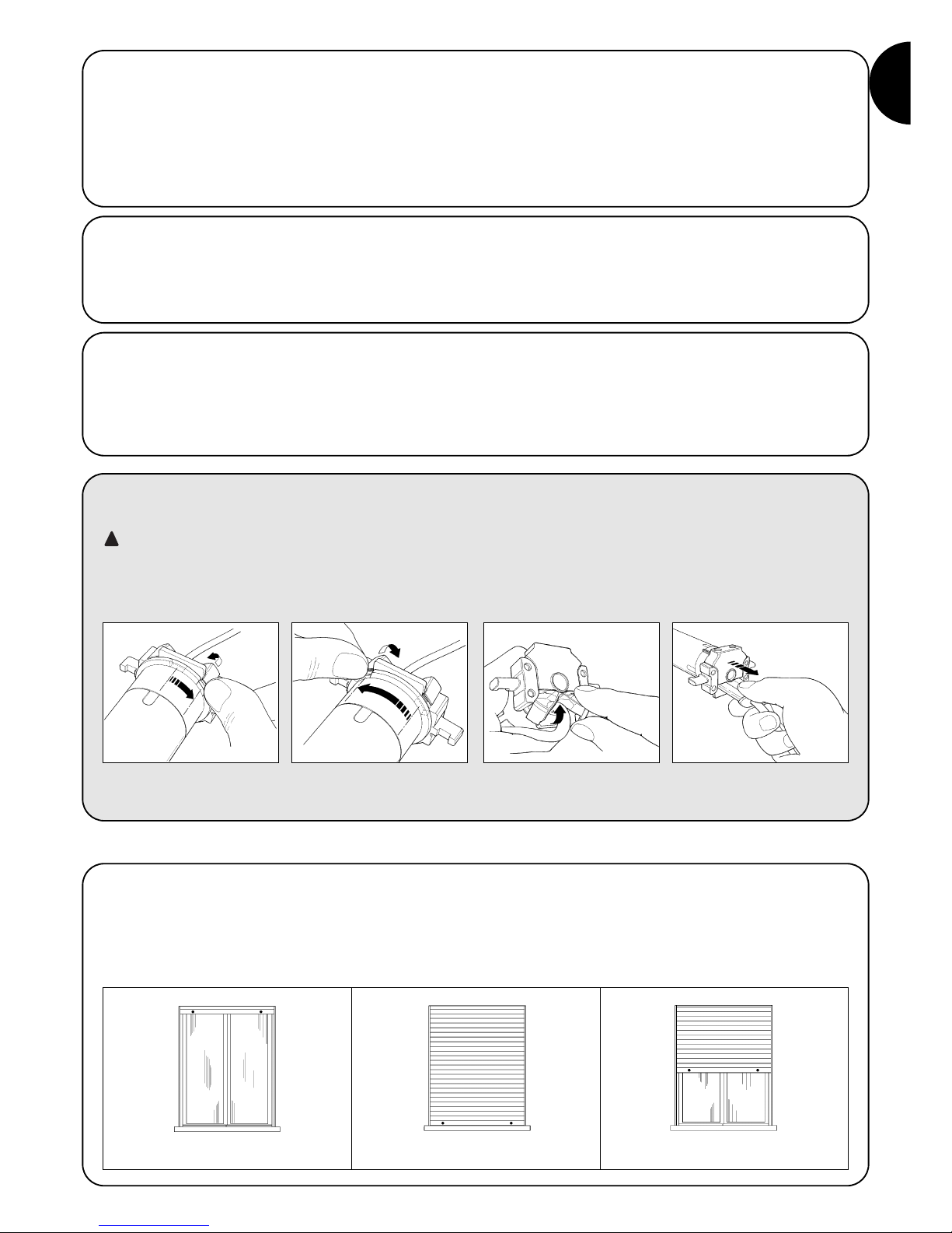
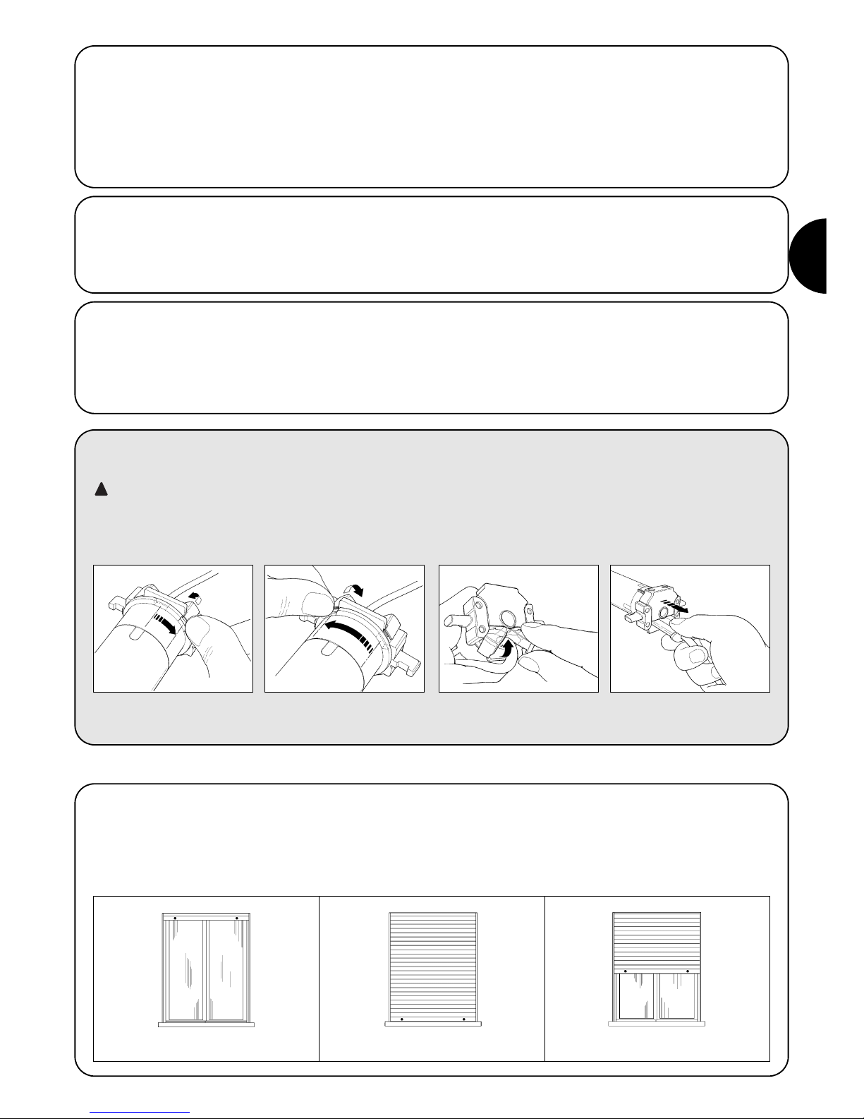
!If it is necessary to disconnect the motor from the power supply cable proceed as shown in the figures below:
!
The NEOMAT series tubular motors are equipped with an electronic
limit switch system. The electronic control unit interrupts the movement when the shutter reaches the programmed open or closed
positions. These positions must be programmed into the memory
after the motor has been installed and the shutter has been fully
mounted.
The motor can still be controlled even if these two positions, “0”
(shutter open) and “1” (shutter close), have not yet been memorised;
however, the movement in this case must be controlled manually. It
is also possible to program an intermediate position (Pos. “I”) for partial opening of the shutter.
Rotate the ring nut until the notch
matches one of the latch-on
teeth, then release.
Repeat the operation for the
other tooth
Bend the cable towards the inside
and remove the protection by rotating it gently towards the outside
Pull out the connector
3) Adjustments
Shutter open (Pos. “0”) Shutter close (Pos.”1”) Intermediate position (“I”)
2.1.2) “TTBUS” input:
The “TTBUS” has been designed to control the control units of
motors for shutters and rolling shutters. This Bus enables separate
control of up to 100 control units by connecting them in parallel
using only 2 conductors (Common and “TTBUS” wires). For further
information see the operating instructions for the remote controls via
“TTBUS”.
2.1.3) Weather sensors:
In the “Weather Sensor” input between the Common wire (black
wire) and the Weather sensor input (orange wire) you can connect a
simple wind sensor (anemometer) or a special wind-sun-rain sensor.
Up to 5 control units can be connected in parallel to a single sensor.
Be careful to observe the polarity of the signals (on all the motors,
the black wire must be connected with the black, the orange with
the orange).
2.1.1) “Step-by-Step” Input:
To control the automation in manual mode it is possible to connect
a simple button (between the Common wire and the Step-by-Step
input). The operating mode follows this sequence: up-stop-downstop.
If the button is held down for more than 3 seconds (but less than 10),
an UP movement is always activated (the one corresponding to key
▲ on the radio controls). If the button is held down for more than 10
seconds, a DOWN movement is always activated (corresponding to
key ▼). This feature can be useful in order to “synchronise” multiple
motors to the same operation regardless of their current status.

4
Programming is divided into three stages:
1. Memorising the transmitters
2. Programming the “0” and “1” positions
3. Optional programming
WARNING: All the transmitter memorisation and parameter programming sequences are timed, i.e. they must
be carried out within set time limits.
• For radio controls designed to handle multiple “units”,
before proceeding with the memorisation you need to
select the unit to which the motor should be associated.
• All the motors within the range of the transmitter can be
programmed by radio; therefore, only the motor involved
in the operation should be kept switched on.
4) Programming
4.1) Memorizing the transmitters
Each radio control is recognised by the receiver incorporated in the NEOMAT A control unit through an individual “code” that is unlike any
other. The control unit must therefore be programmed to recognise each separate radio control through a “memorisation” process.
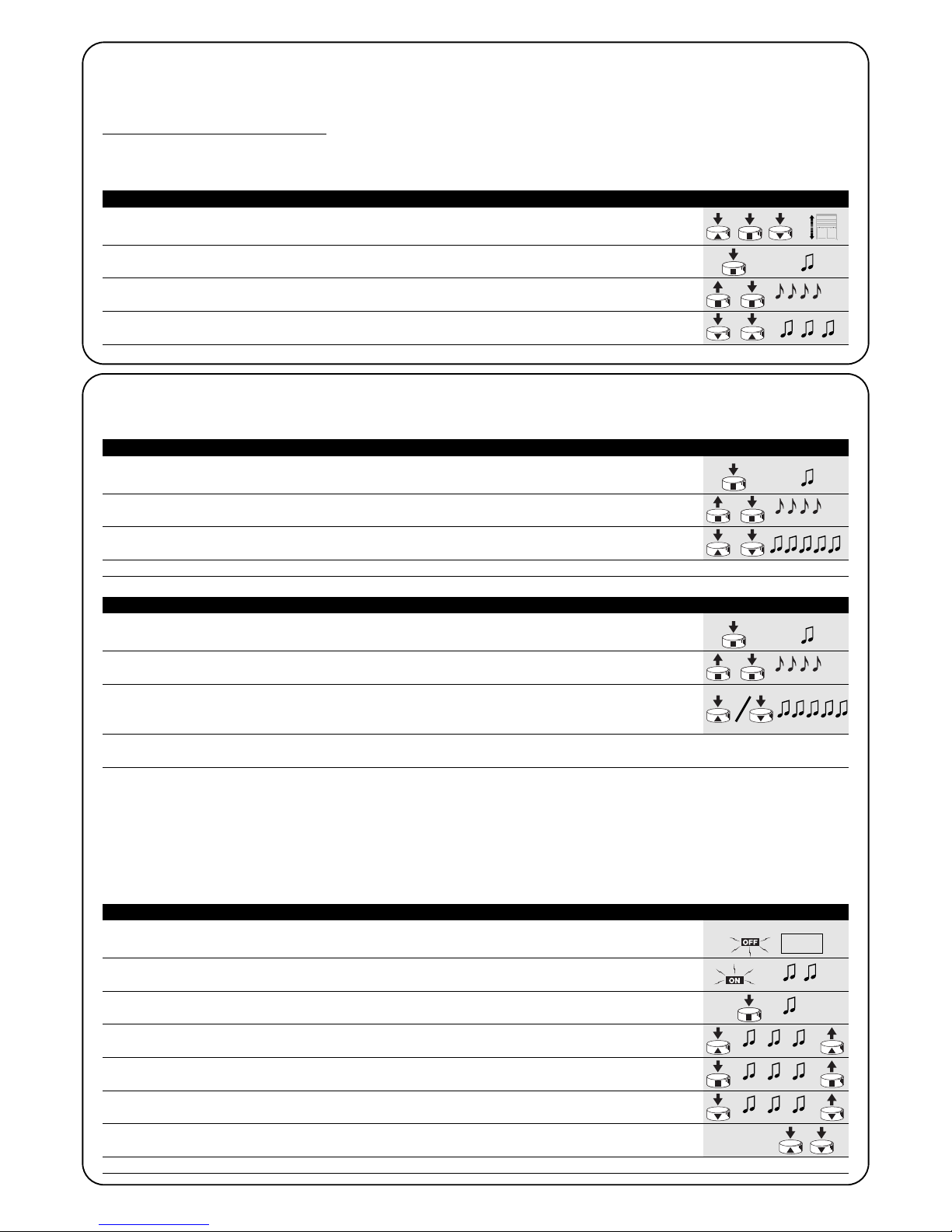
When the memory does not contain any code, you can proceed to program the first radio control by operating as follows:
!
1. When the control unit is switched on, you will hear two long beeps.
2. Within 5 seconds, press and hold down (for approx. 3 seconds) key ■ on the transmitter
that must be memorised 3s
3. When you hear the first of the 3 beeps confirming the memorisation, release key ■.
Note: If the control unit already contains codes, 2 short beeps will be heard when it is switched on. In this case you cannot proceed as
described above but must use the other memorisation method (Table “A2”).
Table “A1” Memorising the first transmitter (fig. 7) Example
1. Press and hold down (approx. 5 seconds) key ■ on the new transmitter until you hear
the beep. New 5s
2. Slowly press key ■ on a previously enabled (old) transmitter 3 times
Old X3
3. Press again key ■ on the new transmitter.
New
4. Finally, 3 beeps will signal that the new transmitter has been correctly memorised.
Note: If the memory is already full (14 codes), 6 beeps will indicate that the transmitter cannot be memorised.
Table “A2” Memorizing additional transmitters (fig 8) Example
When one or more transmitters have already been memorised, additional ones can be enabled by proceeding as follows:
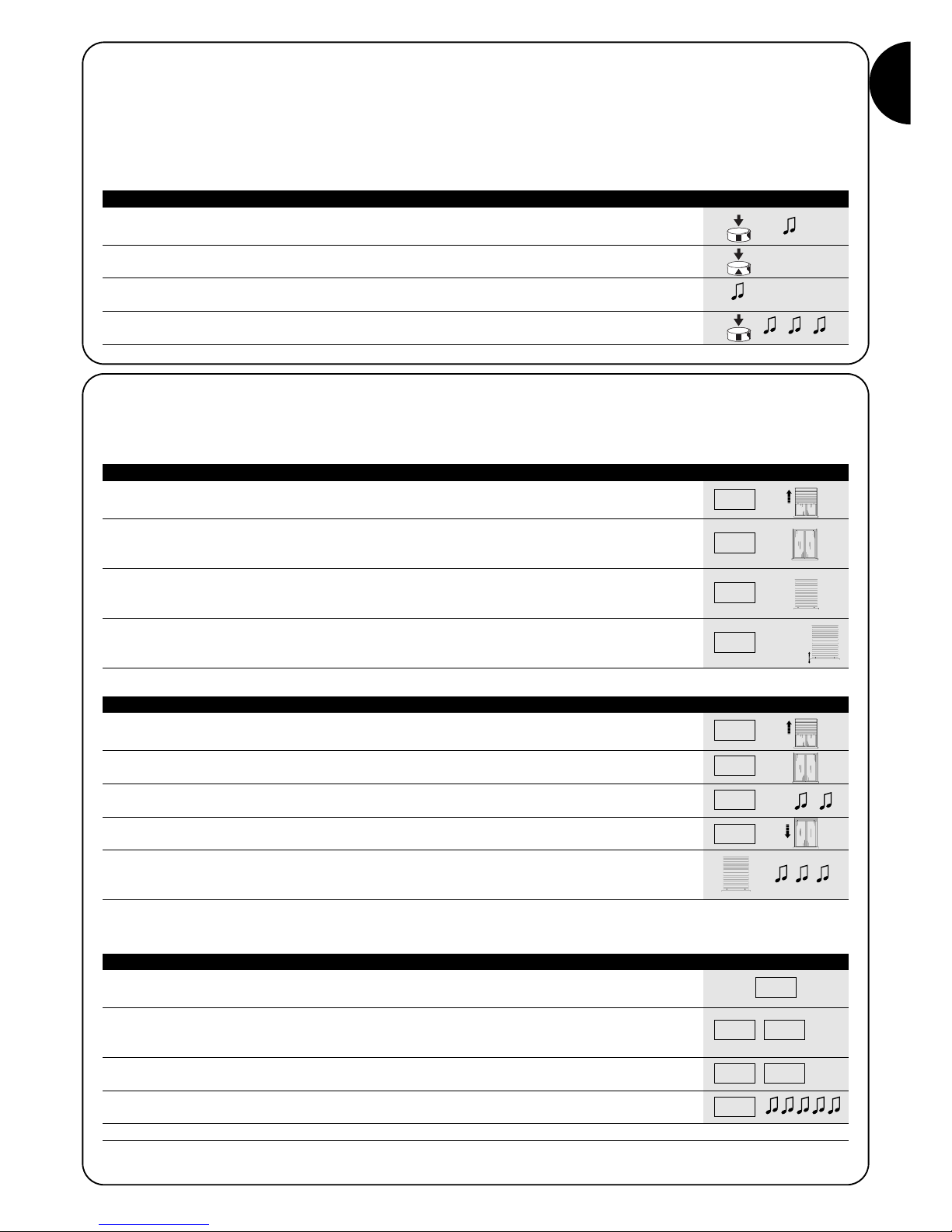
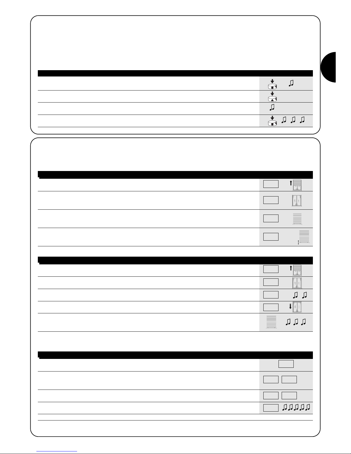
4.2) Programming the “0” and “1” positions
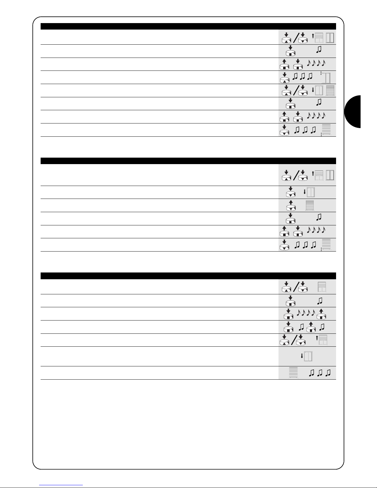
Three basic situations may occur when using rolling shutter automations, ascribable to the presence, or lack, of those elements used to
“block” the travel of the rolling shutter: limit switch “rubber stops” during ascent (which limit the maximum opening) and/or “anti-burglar latches” (which block the possibility to raise the rolling-shutter manually when it is completely closed).
The limit-switches can be programmed differently depending on whether these mechanical stops (rubber stops and/or latches) are present
or not:
Manual programming of the limit-switches (no rubber stops or anti-burglar latches are required)
Semi-automatic programming of the limit-switches (rubber stops are required during ascent)
Automatic programming of the limit-switches (Both rubber stops during ascent, and anti-burglar latches during descent are required)
To program the positions you need to use a previously memorised remote control. Unless the “0” and “1” positions have been memorised in
the control unit, the movements require manual control. Initially the direction of the motor is not defined, but when programming has been
executed, the direction of the motor will be automatically assigned to the remote control keys.

GB
5
1. Press and hold down key ▲ or ▼ on a memorised remote control until the rolling
shutter has reached the required opening position.
2. Press and hold down key ■ on the transmitter until you hear a beep (approx. 5 seconds)
5s
3. Release and then press again key ■ for 5 more seconds until you hear 4 short beeps
5s
4. Press and hold down key ▲ until 3 beeps and a brief movement signal that the opening
position has been memorised.
5. Press and hold down key ▲ or ▼ on a memorised remote control until the rolling
shutter has reached the required closing position.
6. Press and hold down key ■ on the transmitter until you hear a beep (approx. 5 seconds)
5s
7. Release and then press again key ■ for 5 more seconds until you hear 4 short beeps
5s
8. Press key ▼ until 3 beeps and a brief movement signal that the closing “1” position has
been memorised.
N.B.: Key ▲ will now control upward movement while key ▼ the downward movement.
The upward and downwards movements will stop at the programmed positions.
Table “A3” MANUAL Programming the “0” and “1” positions (fig. 9) Example
1. Press and hold down key ▲ or ▼ on a memorised remote control until the rolling shutter has
opened up completely and the motor stops automatically on the rubber stops.
2. Press and hold down key ▼ to lower the shutter
3. Release key ▼ when the shutter has reached the desired position (“1”)
5s
4. Press and hold down key ■ on the transmitter until you hear a beep (approx. 5 seconds)
5s
5. Release and then press again key ■ for 5 more seconds until you hear 4 short beeps
5s
6. Press and hold down key ▼ until 3 beeps and a brief movement signal that the closing “1”
position has been memorised.
N.B.: Key ▲ will now control the upward movement while key ▼ the downward movement.
During ascent, the rolling shutter will stop in correspondence with the rubber stops, whilst during descent in correspondence with the
programmed position.
Table “A4” SEMIAUTOMATIC Programming the “0” and “1” positions (fig. 10) Example
1. Check that the rolling-shutter is at the mid travel stage, using the ▲ key or ▼ on a memorised
remote control if necessary to move the rolling-shutter.
2. Press the ■ key of a transmitter which has already been memorised, and keep it held down
until you hear a beeping noise (this will happen after about 5 seconds). Then release the key. 5s
3. Press the ■ key down for a further 5 seconds until you hear 4 quick beeps, and then
release the key. 5s
4. Press the ■ key once again and keep it held down until you hear the first of the two slow
beeps.
5. The rolling-shutter should move upwards, if it moves downwards, press the ▲ key or ▼ to
make the rolling shutter move upwards.
6. The procedure will continue automatically at this stage:
first the system will find position “0” in correspondence with the opening rubber stops;
following this position “1” in correspondence with the closing anti-burglar latches.
7. The procedure is complete when the rolling-shutter is completely closed and 3 beeps
have sounded.
N.B.: Key ▲ will now control the upward movement, while key ▼ the downward movement.
The upward and downward manoeuvres will stop just before the limits required.
Table “A5” AUTOMATIC Programming the “0” and “1” positions (fig 11) Example
6
4.3) Optional programming
Optional programming operations can only be performed after the “0” and “1” positions have been programmed
Pr
ogramming the intermediate position “I”
If an intermediate position “I” has been memorised, the shutter can be moved to the programmed position by simultaneously pressing keys
▼ and ▲ on the transmitter.
To memorize the intermediate position proceed as follows:
1. Using keys ▲■▼on a remote control, move the shutter to the position that you wish
to memorise as “I”
2. Press and hold down (approx. 5 seconds) key ■ until you hear the beep
5s
3. Release and then press again key ■ for 5 more seconds until you hear 4 short beeps
5s
4. Press keys ▼ and ▲ simultaneously until 3 beeps signal that the position has been
memorised
Table “A6” Programming the intermediate position “I” (fig 12) Example
4.4) Modifying the memorised positions
To modify the memorised positions, first you need to erase them, then you must reprogram the new positions.
If you need to erase all the data contained in the memory of the NEOMAT control unit, carry out the following procedure.
The memory can be erased:
• with a non-memorised transmitter starting from point A.
• with a previously memorised transmitter starting the procedure from point N°1
The following can be erased:
• only the transmitter codes, finishing at point N°4
• all the data (transmitter codes, positions, wind levels, TTBUS address, etc.), completing the procedure.
1. Press and hold down key ■ on a previously memorised transmitter until you hear a beep
(approx. 5 seconds) 5s
2. Release and then press again key ■ for 5 more seconds until you hear 4 short beeps
5s
3. Press keys ▲ and ▼ simultaneously until 5 beeps signal that the intermediate position
has been erased
It will now be possible to programme the new intermediate position (Table “A6”)
Table “A7” Erasing intermediate position “I” (fig 12) Example
1. Press and hold down key ■ on a previously memorised transmitter until you hear a beep
(approx. 5 seconds) 5s
2. Release and then press again key ■ for 5 more seconds until you hear 4 short beeps
5s
3. Press either the ▲ key (if automatic or manual programming has been carried out) or the ▼
key (if semiautomatic programming has been carried out), until you hear 5 beeps.
This indicates that positions “0” and “1” have been deleted.
WARNING: After positions “0” and “1” have been erased, the shutter will only move by manual control, therefore a new position must be
memorised (Tables “A3”, “A4”, “A5”)
Table “A8” Erasing positions “0” and “1” (fig 13) Example
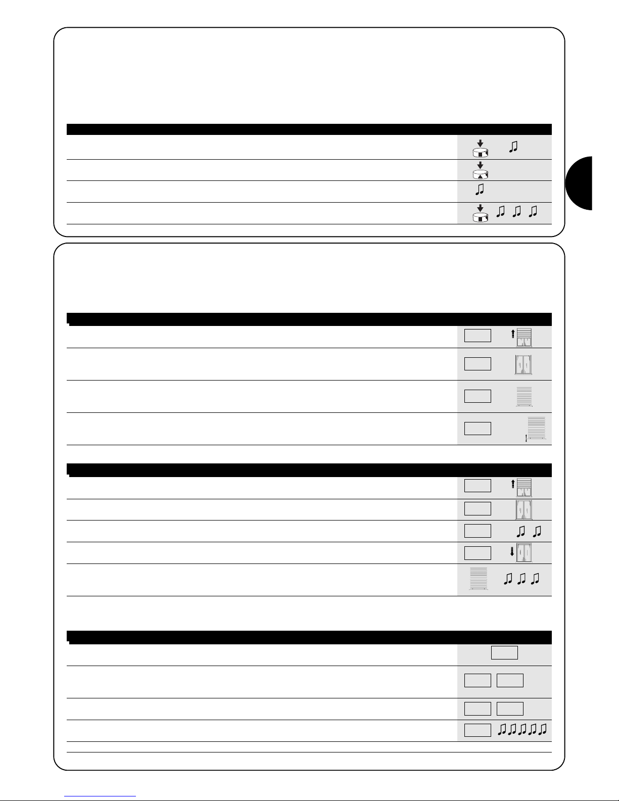
A. Switch the motor off, activate the Step-by-Step input (by connecting up the white and black
wires)and keep it active until the end of the procedure
B. Power the motor and wait for the 2 initial beeps
1. Press and hold down key ■ on a previously memorised transmitter until you hear a beep
(approx. 5 seconds) 5s
2. Press and hold down key ▲ on the transmitter until you hear 3 beeps; release key ▲ exactly
during the third beep. 5s
3. Press and hold down key ■ on the transmitter until you hear 3 beeps; release key ■ exactly
during the third beep
4. Press and hold down key ▼ on the transmitter until you hear 3 beeps; release key ▼ exactly
during the third beep
5. If you wish to erase all the data, press the ▲ and ▼ keys together within 2 seconds and then
release them within 2s
After a few seconds 5 beeps will signal that all the memorised codes have been erased.
Table “A9” Erasing the memory (fig 14) Example
➨
➨
➨
PP
GB
7
1. Press key ■ on a previously memorised transmitter until you hear a beep
(approximately 5 seconds) 5s
2. Press key ▲ slowly as many times (1, 2 or 3) as the number of the desired level
3. After a few seconds you will hear a number of beeps corresponding to the required level
4. Press key ■ to confirm; 3 beeps will confirm the new setting. To abort the procedure without
modifying the previous level, wait at least 5 seconds without confirming
Table “A10” Modifying the cut-in level of the “wind” protection (fig 15) Example
4.5) Programming the weather sensors
If a wind sensor is connected to the “sensors” input, you can select the desired cut-in level from 3 possible levels (1= 15 Km/h, 2= 30 Km/h
and 3= 45 Km/h if the “VOLO” sensor is used). The factory setting is N. 2. When this level is exceeded for over 3 seconds, a command corresponding to key ▲ is activated and all other movements are disabled until the wind speed returns below the programmed value for at least
one minute.
To modify the programmed level:
X1= 15 km/h
X2= 30 km/h
X3= 45 km/h
X1= 15 km/h
X2= 30 km/h
X3= 45 km/h
1. Activate the step-by-step control; if the shutter moves down release the control and repeat
the operation.
2. Keep the step-by-step control active until the motor stops automatically because the
completely open shutter has knocked against the rubber stops (position “0”).
Then release the control
3. Using the step-by-step control (manned control), stop the shutter during the down
movement in the desired closed position (position “1”), so that a subsequent command
will cause the shutter to move up
4. Activate the step-by-step control 2 consecutive times (within 2 seconds) keeping the second
command active for at least 5 seconds (motor off), until 3 beeps and a brief up and down
movement signal that the position has been memorised X2(X5s)
Table “A11” Programming positions “0” and “1” for SEMI-AUTOMATIC research Example
4.6) Programming the positions without a transmitter
Though it is not as easy, it is still possible to program the travel limits and positions “0” and “1” without using the remote control but only the
step-by-step input
Only the SEMI-AUTOMATIC or AUTOMATIC programming is available in this case.
PP
PP
PP
PP
1. Activate the step-by-step control; if the shutter moves down release the control and repeat
the operation.
2. Keep the step-by-step control active until the motor stops automatically because the
completely open shutter has knocked against the rubber stops (position “0”).
3. Continue to keep the control active for another 5 seconds until you hear two beeps,
then release the control. X5s
4. The rolling-shutter will start moving downwards “looking” for position “1”.
This procedure can be interrupted by reactivating the step-by-step control.
5. When the rolling-shutter is closed completely in correspondence with the anti-burglar latches,
the rolling-shutter will stop and you will hear 3 beeps which indicate that positions “0” e “1”
have been successfully programmed.
Note: The partially open position cannot be memorised using the step-by-step control
Table “A12” Programming positions “0” and “1” for AUTOMATIC research Example
PP
PP
PP
PP
If you wish to modify the positions you need to erase all the programmed settings and repeat the procedure from the beginning
1. Activate the step-by-step control; if the shutter moves up release the control and repeat the
operation. 3s
2. Keep the step-by-step control active until the shutter starts moving up after about 3 seconds;
activate the step-by-step control 2 consecutive times (within 2 seconds), keeping the second
command active to stop the shutter and then start moving it down. 3s
3. Repeat the previous step three more times.
At the 3rd attempt the shutter will fail to move up. X3
4. Continue to keep the step-by-step control active for another 10 seconds until 5 beeps signal
that all the positions have been erased
Note: After the positions have been erased, all the movements must be controlled manually
Table “A13” Erasing the positions “0” and “1” using the step-by-step control Example
PP
PP PP
PPPPPP

8
When the motor is switched on, the 2 beeps do not sound
and the Step-by-Step input does not control any movement.
Make sure the motor is powered with the correct voltage; if the power input is correct there is probably a serious fault and the motor
needs replacing.
After a radio command, 6 beeps are heard and the
manoeuvre does not start.
The radio control unit is unsynchronised, repeat the transmitter
memorisation process.
After a command, 10 Beeps sound and then the manoeuvre begins.
The auto-diagnosis of the memorised parameters has detected an
abnormality (incorrect positions, TTBUS address, wind and sun levels,
direction of movement). Check and repeat programming if necessary.
After a command the motor does not turn.
• The thermal protection might have triggered; in this case just wait
for the motor to cool down
• If a wind sensor has been connected, the set threshold might
have been exceeded
•You might try to switch the motor off and back on again; if the 2
beeps do not sound, there is probably a serious fault and the
motor needs replacing
During the UP phase, before reaching the set position
(pos. “0”, pos. “I”), the motor stops and then makes 3
attempts to start up again. This does not necessarily mean trou-
ble: if the programming of positions “0” ”1” was carried out SEMIAUTOMATICALLY: when excessive strain is revealed during the
upward movement, the motor will switch off for approximately 1 second, after which the system will attempt to complete the manoeuvre.
Check for any obstacles which may be obstructing movement.
The motor will stop before reaching the set position (pos.
“0”, pos “I”, pos. “1”) during descent and ascent.
This does not necessarily mean trouble: in case of overload the
motor is switched off. Check to see if any obstacles are obstructing
movement.
The motor turns only if the control is manned.
If positions “0” and “1” have not been programmed the motor rolls
the shutter up or down only through manual control. Program positions “0” and “1”.
Positions “0” and “1” have been programmed, but the
shutter moves down only if the control is manned.
The auto-diagnosis of the memorised parameters has detected an
abnormality in the motor position. Give the command to raise the
shutter and wait for it to reach position “0”
5) What to do if… a small troubleshooting guide!
6) Technical characteristics
NEOMAT A series tubular motors
Supply voltage and frequency : See the technical data on the label attached to each model
Current and power : See the technical data on the label attached to each model
To rque and speed : See the technical data on the label attached to each model
Continuous operating time : Maximum 4 minutes
Work cycle : Maximum 20%
Protection class : IP 44
Operating temperature : -10 ÷ 70 °C
Precision (resolution) of the electronic limit switch : Greater than 0.55° (depending on the NEOMAT A version)
Electronic control unit
Signal voltage (step-by-step, sensors) : Approx. 24Vdc
Wind sensor (anemometer) levels : approx. 30 or 15 or 45 Km/h (with VOLO anemometer)
Length of signal cables (step-by-step, sensors) : max. 30m if near other cables, otherwise 100m
Radio receiver
Frequency : 433.92 MHz
Coding : 52 Bit rolling code FLOR
Range of ERGO and PLANO transmitters : Estimated 200 m in the open and 35 m inside buildings.
Nice S.p.a. reserves the right to modify its products at any time without notice

GB
9

1010
Avvertenze:
I motori serie “NEOMAT A” sono stati realizzati per automatizzare il movimento di tapparelle; ogni altro uso è improprio e vietato. I motori sono progettati per uso residenziale; è previsto un tempo di lavoro continuo massimo di 4 minuti con un ciclo del 20%. Nella scelta del tipo di motore in
funzione dell’applicazione, si dovrà considerare la coppia nominale ed il
tempo di funzionamento riportati sui dati targa. Il diametro minimo del
tubo in cui il motore può essere installato è 40mm per NEOMAT SA,
52mm per NEOMAT MA e 70mm per NEOMAT LA. L’installazione deve
essere eseguita da personale tecnico nel pieno rispetto delle norme di
sicurezza. Negli apparecchi ad uso esterno, il cavo di alimentazione in
PVC deve essere installato dentro un condotto di protezione.
Non sottoporre il motore tubolare a schiacciamenti, urti, cadute o contatto con liquidi di qualunque natura; non forare né applicare viti per tutta la
lunghezza del tubolare (fig. 1). Rivolgersi a personale tecnico competente
per manutenzioni e riparazioni.
Attenzione: alcune fasi della programmazione possono sfruttare i fermi
meccanici della tapparella (tappi e/o molle anti-intrusione). In questo caso
è indispensabile scegliere il motore con la coppia più adatta all’applicazione considerando l’effettivo peso della tapparella evitando motori troppo
potenti.
I motori tubolari NEOMAT SA Ø35mm, NEOMAT MA Ø45mm (fig.2)
e NEOMAT LA Ø58mm contengono una centrale elettronica con
ricevitore radio incorporato che opera alla frequenza di 433.92 MHz
con tecnologia rolling code, per garantire elevati livelli di sicurezza.
Per ogni motore è possibile memorizzare fino a 14 radiocomandi della serie “ERGO” e “PLANO” (fig.3) o “VOLO S RADIO”.
La centrale incorporata nel motore dispone anche di un sistema di
finecorsa elettronico ad elevata precisione che è in grado di rilevare
costantemente la posizione della tapparella. Attraverso una operazione di programmazione vengono memorizzati i limiti del movimento, cioè tapparella chiusa e tapparella aperta (più una eventuale posizione intermedia); dopo ogni comando il movimento si fermerà automaticamente al raggiungimento di queste posizioni.
La centrale riesce anche a rilevare brusche variazioni e sforzi del
motore interrompendo prontamente il movimento, questa caratteristica è sfruttata anche per effettuare la programmazione automatica
dei limiti di manovra se la tapparella dispone di tappi di finecorsa
superiori e di molle anti-intrusione.
La programmazione dei limiti di movimento e di alcune funzioni
aggiuntive è eseguibile dai radiocomandi, un “Bip” acustico ne guiderà le varie fasi. E’ possibile comandare i motori anche con un pulsante esterno (con funzione passo-passo) oppure via Bus “TTBUS”.
Eventuali sensori opzionali di vento, sole e pioggia possono attivare
automaticamente il sistema quando le condizioni climatiche lo richiedono.
1) Descrizione del prodotto
2) Installazione
Preparare il motore con la seguente sequenza di operazioni (fig. 5):
1. Infilare la ghiera a folle (E) sul motore (A) fino ad inserirsi nel
corrispondente anello a folle (F).
2. Inserire la ghiera di trascinamento (D) sull’albero del motore.
Su NEOMAT SA il fissaggio della ghiera è automatico a scatto
3. Su NEOMAT MA, fissare la ghiera di trascinamento con il seeger
a pressione
Figura 4
A: Motore tubolare NEOMAT A
B: Fermagli o copiglie per fissaggio
C: Supporto e distanziale
D: Ghiera di trascinamento
E: Ghiera a folle
F: Anello a folle
NEOMAT A è prodotto da Motus s.p.a. (TV) I. ERGO, PLANO, VOLO sono prodotti da Nice s.p.a.(TV) I. Motus s.p.a. è una società del gruppo Nice s.p.a.
Introdurre il motore così assemblato nel tubo di avvolgimento della
tapparella fino a toccare l’estremità della ghiera a folle (E). Fissare il
tubo alla ghiera di trascinamento (D) mediante vite M4x10 in modo
da evitare possibili slittamenti e spostamenti assiali del motore (fig.
6). Infine bloccare la testa del motore all’apposito supporto (C), con
l’eventuale distanziale mediante i fermagli o la copiglia (B).
2.1) Collegamenti elettrici
ATTENZIONE: nei collegamenti del motore è necessario prevedere un dispositivo onnipolare di sconnessione
dalla rete elettrica con distanza tra i contatti di almeno 3
mm (sezionatore oppure spina e presa ecc.).
ATTENZIONE: rispettare scrupolosamente i collegamenti previsti; in caso di dubbio non tentare invano ma
consultare le apposite schede tecniche di approfondimento disponibili anche sul sito "www.niceforyou.com".
Un collegamento errato può provocare guasti o situazioni
di pericolo.
Il cavo per i collegamenti elettrici del motore NEOMAT A dispone di
6 conduttori di collegamento:
• Linea di alimentazione dalla rete elettrica: Fase, Neutro e Terra
• Segnali di comando in bassissima tensione (SELV): Passo-Passo
o Bus “TTBUS” e sensori climatici
!
!
Marrone = Fase
Blu = Neutro
Giallo/Verde = Terra
Nero = Comune (0V)
Bianco = Passo-P. + “TTBUS”
Arancio = Sensori climatici
Etichetta
gialla
Etichetta
verde

I
1111
2.2) Connettore e cavo di alimentazione (questo capitolo è relativo solo alla versione NEOMAT A ed è rivolto solo al personale
tecnico dell’assistenza).
ATTENZIONE: se il cavo di alimentazione fosse danneggiato dovrà essere sostituito da uno identico disponibile pres-
so il costruttore o il suo servizio di assistenza.
Qualora sia necessario scollegare il motore dal cavo di alimentazione; agire come indicato nelle figure seguenti:
!
I motori tubolari serie NEOMAT A dispongono di un sistema di fine
corsa elettronico, la centrale elettronica interrompe il movimento
quando la tapparella raggiunge le posizioni di chiusura e di apertura
programmate. Queste posizioni vanno memorizzate con una opportuna programmazione che deve essere fatta direttamente con motore installato e tapparella completamente montata.
Se le posizioni “0” (tapparella aperta) e “1” (tapparella chiusa) non
sono ancora state memorizzate è possibile comandare ugualmente
il motore ma il movimento avverrà a uomo presente. E’ possibile programmare anche una posizione intermedia (Pos. “I”) per una apertura parziale della tapparella.
Ruotare la ghiera fino a far coincidere lo smusso con uno dei denti
di aggancio, quindi sganciare.
Ripetere l’operazione per l’altro
dente.
Piegare il cavo verso l’interno e
togliere la protezione ruotandola
delicatamente verso l’esterno.
Sfilare il connettore tirandolo
3) Regolazioni
Tapparella aperta (Pos. “0”) Tapparella chiusa (Pos.”1”) Posizione intermedia (“I”)
2.1.2) Ingresso “TTBUS”:
Il “TTBUS” è un Bus sviluppato per poter controllare le centrali di
comando dei motori per tende e tapparelle. Il Bus prevede la possibilità di controllare singolarmente fino a 100 centrali collegandole
semplicemente in parallelo con soli 2 conduttori (Comune e
“TTBUS”). Ulteriori informazioni sono contenute nelle istruzioni nei
telecomandi via “TTBUS”.
2.1.3) Sensori climatici:
Nell’ingresso “Sensori climatici” tra Comune (conduttore nero) e l’ingresso Sensori climatici (conduttore arancio) si può collegare un
semplice sensore di vento (anemometro) oppure uno speciale sensore di vento-sole-pioggia.
Ad uno stesso sensore si possono collegare fino a 5 centrali in parallelo rispettando la polarità dei segnali (su tutti i motori, il conduttore
nero va collegato con il nero e l’arancio con l’arancio).
2.1.1) Ingresso “Passo-Passo”:
Per comandare l’automazione in modo manuale è possibile collegare un semplice pulsante (tra Comune e l’ingresso Passo-Passo).
Il modo di funzionamento segue la sequenza: salita-stop-discesastop. Se il tasto viene mantenuto premuto per più di 3 secondi (ma
meno di 10 ) si attiva sempre una manovra di salita (quella corrispondente al tasto ▲ dei radiocomandi).
Se il tasto rimane premuto oltre i 10 secondi si attiva sempre una
manovra di discesa (corrispondente al tasto ▼). Questa particolarità
può essere utile per “sincronizzare” più motori verso la stessa manovra indipendentemente dallo stato in cui si trovavano.

12
La programmazione è divisa in 3 parti:
1. Memorizzazione dei trasmettitori
2. Programmazione delle posizioni “0” e “1”
3. Programmazioni opzionali
ATTENZIONE: Tutte le sequenze di memorizzazione dei
trasmettitori e delle programmazioni dei parametri sono a
tempo, cioè devono essere eseguite entro i limiti di tempo
previsti.
• Con radiocomandi che prevedono più “gruppi”, prima di
procedere alla memorizzazione occorre scegliere il
gruppo al quale associare il motore.
• La programmazione via radio può avvenire in tutti i
motori che si trovano nel raggio della portata del trasmettitore; è quindi opportuno tenere alimentato solo
quello interessato all’operazione.
4) Programmazione
4.1) Memorizzazione dei trasmettitori
Ogni radiocomando viene riconosciuto dalla ricevente incorporata nella centrale di NEOMAT A attraverso un “codice” diverso da ogni altro.
E’ necessaria quindi una fase di “memorizzazione” attraverso la quale si predispone la centrale a riconoscere ogni singolo radiocomando.
Quando la memoria non contiene nessun codice si può precedere all’inserimento del primo radiocomando con la seguente modalità:
!
1. Appena data alimentazione alla centrale, si sentiranno 2 bip lunghi (biiip)
2. Entro 5 secondi premere e tener premuto il tasto ■ del trasmettitore da memorizzare
(per circa 3 secondi) 3s
3. Rilasciare il tasto ■ quando si sentirà il primo dei 3 bip che confermano la memorizzazione
Nota: Se la centrale contiene già dei codici, all’accensione si udiranno 2 bip brevi (bip) e non si potrà procedere come
descritto sopra ma occorre usare l’altra modalità di memorizzazione (Tabella “A2”)
Tabella “A1” Memorizzazione del primo trasmettitore (fig 7) Esempio
1. Tenete premuto il tasto ■ del nuovo trasmettitore fino a sentire un bip (dopo circa 5 secondi)
Nuovo 5s
2. Lentamente premere per 3 volte il tasto ■ di un trasmettere già abilitato (vecchio)
Vecchio X3
3. Premere ancora il tasto ■ del nuovo trasmettitore.
Nuovo
4. Alla fine 3 bip segnaleranno che il nuovo trasmettitore è stato memorizzato correttamente.
Nota: Se la memoria è piena (14 codici), 6 Bip indicheranno il trasmettitore non può essere memorizzato.
Tabella “A2” Memorizzazione di altri trasmettitori (fig 8) Esempio
Quando uno o più trasmettitori sono già stati memorizzati, è possibile abilitarne altri in questo modo:
4.2) Programmazione delle posizioni “0” e “1”
Nel caso di automazioni di tapparelle si possono presentare sostanzialmente 3 casi, questi sono riconducibili alla presenza o meno di elementi di “blocco” della corsa della tapparella: “tappi” di fine corsa in salita (che limitano l’apertura massima) e/o “molle anti-intrusione” (che
impediscono di alzare manualmente la tapparella quando è completamente chiusa).
A seconda della presenza o meno di questi limiti di corsa meccanici (tappi e/o molle) la programmazione dei fine corsa può essere fatta in
maniera diversa:
Programmazione manuale dei fine corsa (Non sono necessari tappi o molle anti-intrusione)
Programmazione semiautomatica dei fine corsa (E’ necessaria la presenza dei tappi in salita)
Programmazione automatica dei fine corsa (E’ necessaria sia la presenza dei tappi in salita che delle molle anti-intrusione in discesa)
Per programmare le posizioni bisogna utilizzare un telecomando già memorizzato. Fino a quando nella centrale non vengono memorizzate
le posizioni “0” e “1” valide, i movimenti sono a uomo presente. Inizialmente la direzione del motore non è definita, ma al completamento della programmazione la direzione del motore viene automaticamente assegnata ai tasti dei telecomandi.

I
13
1. Premere e tenere premuto il tasto ▲ o il tasto ▼ di un telecomando memorizzato fino a
portarsi nella posizione di apertura desiderata
2. Tenere premuto il tasto ■ del trasmettitore fino a sentire un bip (dopo circa 5 secondi)
5s
3. Rilasciare e premere nuovamente per altri 5 secondi il tasto ■ fino a sentire 4 bip veloci
5s
4. Premere il tasto ▲ fino a quando 3 bip e un breve movimento segnalano che la posizione
di apertura “0” è stata memorizzata
5. Premere e tenere premuto il tasto ▲ o il tasto ▼ del telecomando memorizzato fino a
portarsi nella posizione di chiusura desiderata
6. Tenere premuto il tasto ■ del trasmettitore fino a sentire un bip (dopo circa 5 secondi)
5s
7. Rilasciare e premere nuovamente per altri 5 secondi il tasto ■ fino a sentire 4 bip veloci
5s
8. Premere il tasto ▼ fino a quando 3 bip e un breve movimento segnalano che la posizione di
chiusura “1” è stata memorizzata
Nota: Ora il tasto ▲ comanderà la manovra di salita mentre il tasto ▼ quella di discesa.
La manovra in salita e quella in discesa si fermeranno in corrispondenza delle posizioni programmate.
Tabella “A3” Programmazione MANUALE delle Posizioni “0” e “1” (fig 9) Esempio
1. Premere e tenere premuto il tasto ▲ o il tasto ▼ di un telecomando memorizzato fino
a quando si raggiunge l’apertura completa della tapparella e il motore si ferma
automaticamente sui tappi in salita.
2. Premere e tenere premuto il tasto ▼ che fa scendere la tapparella
3. Rilasciare il tasto ▼ quando la tapparella raggiunge la posizione desiderata (“1”)
5s
4. Tenere premuto il tasto ■ del trasmettitore fino a sentire un bip (dopo circa 5 secondi)
5s
5. Rilasciare e premere nuovamente per altri 5 secondi il tasto ■ fino a sentire 4 bip veloci
5s
6. Premere il tasto ▼ fino a quando 3 bip e un breve movimento segnalano che la posizione
di chiusura “1” è stata memorizzata
Nota: Ora il tasto ▲ comanderà la manovra di salita mentre il tasto ▼ quella di discesa.
In salita la tapparella si fermerà in corrispondenza dei tappi, in discesa in corrispondenza della posizione programmata.
Tabella “A4” Programmazione SEMIAUTOMATICA delle Posizioni “0” e “1”(fig 10) Esempio
1. Verificare che la tapparella sia a metà corsa circa, eventualmente utilizzare i tasti ▲ e ▼
di un telecomando già memorizzato per spostare la tapparella a metà della corsa.
2. Premere e tenere premuto il tasto ■ di un trasmettitore già memorizzato fino a sentire un
bip (dopo circa 5 secondi) e rilasciare. 5s
3. Premere nuovamente per altri 5 secondi il tasto ■ fino a sentire 4 bip veloci e rilasciare.
5s
4. Premere nuovamente il tasto ■ fino a sentire il primo dei 2 bip lenti
5. La tapparella dovrà muoversi verso l’alto, se il movimento è verso il basso bisogna premere
il tasto ▲ o ▼ per per far muovere la tapparella verso l’alto
6. La procedura a questo punto proseguirà automaticamente:
prima verrà trovata la posizione “0” in corrispondenza dei tappi in apertura e
successivamente la posizione “1” in corrispondenza delle molle anti-intrusione in chiusura.
7. La procedura si concluderà con la tapparella completamente chiusa e con una
segnalazione sonora di 3 bip
Nota: Ora il tasto ▲ comanderà la manovra di salita mentre il tasto ▼ comanderà la manovra di discesa.
La manovra in salita e quella in discesa si fermeranno poco prima dei limiti ricercati.
Tabella “A5” Programmazione AUTOMATICA delle Posizioni “0” e “1” (fig 11) Esempio

14
4.3) Programmazioni opzionali
Le programmazioni opzionali sono possibili solo dopo aver concluso le programmazioni delle posizioni “0” e “1”
Memorizzazione della posizione intermedia “I”
Se è memorizzata una posizione intermedia “I” è possibile muovere la tapparella nella posizione programmata premendo contemporaneamente i 2 tasti ▼▲ del trasmettitore.
Per memorizzare la posizione intermedia seguire questa procedura:
1. Utilizzando i tasti ▲■▼di un telecomando portare la tapparella dove si desidera
memorizzare la posizione “I”
2. Tenere premuto il tasto ■ fino a sentire un bip (dopo circa 5 secondi)
5s
3. Rilasciare e premere nuovamente per altri 5 secondi il tasto ■ fino a sentire 4 bip veloci
5s
4. Premere contemporaneamente i tasti ▼ ▲ fino a quando 3 bip segnalano che la quota
è stata memorizzata
Tabella “A6” Programmazione posizione intermedia “I” (fig 12) Esempio
4.4) Modifica delle posizioni memorizzate
Per modificare le posizioni memorizzate è necessario prima cancellarle e poi riprogrammare le nuove posizioni.
Se dovesse rendersi necessario cancellare tutti dati contenuti nella memoria della centrale di NEOMAT A, si può eseguire questa procedura.
La cancellazione della memoria è possibile:
• con un trasmettitore non memorizzato iniziando dal punto A.
• con uno già memorizzato iniziando la procedura dal punto N°1
Si possono cancellare:
• solo i codici dei trasmettitori, terminando nel punto N°4
• tutti i dati (codici dei trasmettitori, posizioni, livello del vento e sole, indirizzo TTBUS, ecc.) completando la procedura.
1. Tenere premuto il tasto ■ di un trasmettitore già memorizzato fino a sentire un bip
(dopo circa 5 secondi) 5s
2. Rilasciare e premere nuovamente per altri 5 secondi il tasto ■ fino a sentire 4 bip veloci
5s
3. Premere contemporaneamente i tasti ▲ ▼ fino a quando 5 bip segnalano che la posizione
intermedia è stata cancellata
Ora sarà possibile programmare la nuova posizione intermedia (Tabella “A6”)
Tabella “A7” Cancellazione della posizione intermedia “I” (fig 12) Esempio
1. Tenere premuto il tasto ■ di un trasmettitore già memorizzato fino a sentire un bip
(dopo circa 5 secondi) 5s
2. Rilasciare e premere nuovamente per altri 5 secondi il tasto ■ fino a sentire 4 bip veloci
5s
3. Premere il tasto ▲ (nel caso sia stata effettuata la programmazione automatica o manuale)
o il tasto ▼ (nel caso di programmazione semiautomatica), fino a quando 5 bip segnalano
che le posizioni “0” e “1” sono state cancellate
ATTENZIONE: Dopo aver cancellato le posizioni “0” e “1” la tapparella si muoverà a uomo presente ed è necessario memorizzare le nuove
posizioni (Tabelle “A3”, “A4”, “A5”)
Tabella “A8” Cancellazione posizioni “0” e “1” (fig 13) Esempio
A. A motore non alimentato attivare l’ingresso passo-passo (collegare il filo bianco e nero)
e mantenerlo attivo fino alla fine della procedura
B. Alimentare il motore ed attendere i 2 bip iniziali.
1. Tenere premuto il tasto ■ di un trasmettitore fino a sentire un bip
(dopo circa 5 secondi). 5s
2. Tenere premuto il tasto ▲ del trasmettitore fino a sentire 3 bip; rilasciare il tasto ▲
esattamente durante il terzo bip. 5s
3. Tenere premuto il tasto ■ del trasmettitore fino a sentire 3 bip; rilasciare il tasto ■
esattamente durante il terzo bip.
4. Tenere premuto il tasto ▼ del trasmettitore fino a sentire 3 bip; rilasciare il tasto ▼
esattamente durante il terzo bip.
5. Se si vogliono cancellare tutti i dati, entro 2 secondi, premere assieme i due tasti ▲ e ▼,
poi rilasciarli. entro 2s
Dopo qualche secondo 5 bip segnalano che tutti i codici in memoria sono stati cancellati.
Tabella “A9” Cancellazione della memoria (fig 14) Esempio
➨
➨
➨
PP
I
15
1. Premere il tasto ■ di un trasmettitore già memorizzato fino a sentire un bip
(dopo circa 5 secondi). 5s
2. Lentamente premere il tasto ▲ un numero di volte (1, 2 o 3) pari al livello desiderato.
3. Dopo qualche istante si sentirà un numero di bip uguale al livello richiesto
4. Premere il tasto ■ per confermare, 3 bip segnalano la nuova programmazione. Per abortire la
procedura senza cambiare il livello precedente aspettare almeno 5 secondi senza confermare.
Tabella “A10” Cambiare il livello di intervento della protezione “vento” (fig 15) Esempio
4.5) Programmazione sensori climatici
Se all’ingresso “sensori” viene collegato un sensore di vento è possibile selezionare il livello di intervento tra 3 livelli possibili (1°= 15Km/h, 2°=
30Km/h e 3°= 45 Km/h se utilizzato sensore “VOLO”), in origine il livello impostato è il N°2. Quando il livello viene superato per oltre 3 secondi, si attiva un comando equivalente al tasto ▲ e viene bloccato qualsiasi altro movimento fino a che il vento non ritorna sotto al livello programmato per almeno un minuto.
Per modificare il livello programmato:
X1= 15 km/h
X2= 30 km/h
X3= 45 km/h
X1= 15 km/h
X2= 30 km/h
X3= 45 km/h
1. Attivare il comando di passo-passo; se la tapparella si muove in discesa rilasciare il
comando e ripetere l’operazione.
2. Tenere attivo il comando di passo-passo fino a quando il motore si ferma automaticamente
perché la tapparella completamente aperta ha urtato i tappi (posizione “0”).
Poi rilasciare il comando
3. Utilizzando il comando di passo passo (funzionamento a uomo presente) fermare, durante
il movimento di discesa, la tapparella in corrispondenza del punto di chiusura desiderato
(posizione “1”), in modo tale che un successivo comando provochi la salita della tapparella
4. Attivare per 2 volte consecutive (entro 2 secondi) il passo passo mantenendo attivo il secondo
comando per almeno 5 secondi (motore fermo), fino a quando 3 bip e un breve movimento
di salita e discesa segnalano che la posizione è stata memorizzata X2(X5s)
Tabella “A11” Programmazione posizioni “0” e “1” con ricerca SEMIAUTOMATICA Esempio
4.6) Programmazione delle posizioni senza trasmettitore
Anche se in maniera meno agevole, è possibile programmare i limiti di corsa e le posizioni “0” e “1” senza telecomando, ma utilizzando solamente l’ingresso passo-passo.
In questo caso sono possibili solo le programmazioni SEMIAUTOMATICA e AUTOMATICA.
PP
PP
PP
PP
1. Attivare il comando di passo-passo; se la tapparella si muove in discesa rilasciare il
comando e ripetere l’operazione.
2. Tenere attivo il comando di passo-passo fino a quando il motore si ferma automaticamente
perché la tenda è completamente avvolta (posizione “0”).
3. Continuare a mantenere attivo il comando per altri 5 secondi fino a quando si sentono 2 bip,
rilasciare il comando. X5s
4. La tapparella inizia a muoversi in discesa per ricercare la posizione “1”.
La procedura può essere interrotta attivando nuovamente il comando di passo-passo
5. Quando la tapparella raggiunge la completa chiusura in corrispondenza delle molle
anti-intrusione, la tapparella si ferma e segnala con 3 bip l’avvenuta programmazione delle
posizioni “0” e “1”
Nota: Tramite comando di passo-passo non è possibile memorizzare la quota di apertura parziale.
Tabella “A12” Programmazione posizioni “0” e “1” con ricerca in AUTOMATICO Esempio
PP
PP
PP
PP
Se si vogliono modificare le posizioni è necessario cancellare tutte le impostazioni eseguite e ripetere nuovamente tutta la procedura
1. Attivare il comando di passo-passo; se la tapparella si muove in salita rilasciare il comando
e ripetere l’operazione. 3s
2. Mantenere attivo il comando fino a quando dopo circa 3 secondi parte una manovra di
salita; attivare per 2 volte consecutive (entro 2 secondi) il passo passo, mantenendo attivo
il 2° comando, per fermare e far ripartire in discesa la tapparella. 3s
3. Ripetere il punto precedente per altre 3 volte.
Al 3° tentativo la manovra in salita non parte più. X3
4. Continuare a mantenere attivo il comando di passo passo per altri 10 secondi fino a quando
5 bip
segnalano che tutte le posizioni sono state cancellate.
Nota: Dopo la cancellazione delle posizioni i movimenti sono eseguiti a uomo presente
Tabella “A13” Cancellazione delle posizioni “0” e “1” tramite comando passo-passo Esempio
PP
PP PP
PPPPPP

16
Dopo l’alimentazione il motore non emette i 2 Bip e l’ingresso Passo-Passo non comanda nessun movimento.
Controllare che il motore sia alimentato alla tensione di rete prevista,
se l’alimentazione è corretta è probabile vi sia un guasto grave ed il
motore deve essere sostituito.
Dopo un comando via radio si sentono 6 Bip e la manovra
non parte.
Il radiocomando e fuori sincronismo, bisogna ripetere la memorizzazione del trasmettitore.
Dopo un comando si sentono 10 Bip poi parte la manovra.
L’ autodiagnosi dei parametri in memoria ha rilevato qualche anomalia (posizioni,indirizzo TTBUS, livello vento e sole, direzione del movimento sono errati) controllare ed eventualmente ripetere le programmazioni
Dopo un comando il motore non si muove.
• Potrebbe essere intervenuta la protezione termica, in questo caso
basta aspettare che il motore si raffreddi.
•Se è collegato un sensore di vento potrebbe essere superata la
soglia impostata.
•Altrimenti provare a spegnere e riaccendere il motore, se non si
sentono 2 bip è probabile vi sia un guasto grave ed il motore deve
essere sostituito.
In salita, prima di raggiungere la posizione prevista (pos.
“0”, pos. “I”), il motore si ferma e poi si sente che per 3
tentativi cerca di ripartire.
Può essere normale se si è eseguita la programmazione delle posizioni “0” ”1” in modalità SEMIAUTOMATICA: in salita quando viene
rilevato uno sforzo eccessivo, il motore viene spento per circa 1
secondo e poi si ritenta di portare a termine la manovra; verificare se
ci sono ostacoli che impediscono il movimento.
In discesa o in salita prima di raggiungere la posizione
prevista (pos. “0”, pos “I”, pos. “1”), il motore si ferma.
Può essere normale: quando viene rilevato uno sforzo eccessivo , il
motore viene spento; verificare se ci sono ostacoli che impediscono
il movimento
Il motore si muove solo a “uomo presente”.
Se le posizioni “0” e “1” non sono state programmate il movimento
del motore in salita e in discesa avviene solo a uomo presente.
Programmare le posizioni “0” e “1”
La posizioni “0” e “1” sono programmate, ma in discesa si
ha un movimento a uomo presente.
L’ autodiagnosi dei parametri in memoria ha rilevato una anomalia
nella posizione del motore. Comandare la tenda in salita e attendere
che raggiunga la posizione “0”
5) Cosa fare se... cioè piccola guida se qualcosa non va!
6) Caratteristiche tecniche
Motori tubolari serie NEOMAT A
Tensione di alimentazione e frequenza : Vedere i dati tecnici sull’etichetta di ogni modello
Corrente e potenza : Vedere i dati tecnici sull’etichetta di ogni modello
Coppia e velocità : Vedere i dati tecnici sull’etichetta di ogni modello
Te mpo di funzionamento continuo : Massimo 4 minuti
Ciclo di lavoro : Massimo 20%
Grado di protezione : IP 44
Temperatura di funzionamento : -10 ÷ 70 °C
Precisione (risoluzione) del finecorsa elettronico : maggiore di 0,55° (dipende dalla versione del NEOMAT A)
Centrale elettronica
Tensione segnali (passo-passo, sensori) : Circa 24Vdc
Livelli sensore vento (anemometro) : Circa 30 oppure 15 o 45 Km/h (con anemometro VOLO)
Lunghezza cavi segnali (passo-passo, sensori) : massimo 30m se in vicinanza ad altri cavi, altrimenti 100m
Ricevitore radio
Frequenza : 433.92 MHz
Codifica : 52 Bit rolling code FLOR
Portata dei trasmettitori ERGO e PLANO : Stimata in 200 m se spazio libero e 35 m se all’interno di edifici.
Nice S.p.a. si riserva il diritto di apportare modifiche ai prodotti in qualsiasi momento riterrà necessario.

I
17
18
Avertissements:
Les moteurs série “NEOMAT A” ont été réalisés pour automatiser le mouvement de volets roulants; toute autre utilisation est impropre et interdite.
Les moteurs sont projetés pour usage résidentiel; le temps de travail
continu maximum prévu est de 4 minutes avec un cycle de 20%. Dans le
choix du type de moteur en fonction de l’application, il faudra considérer
le couple nominal et le temps de fonctionnement indiqués sur les données
de la plaque. Le diamètre minimum du tube dans lequel le moteur peut
être installé est 40 mm pour NEOMAT SA, 52 mm pour NEOMAT MA et
70 mm pour NEOMAT LA. L’installation doit être effectuée par du personnel technique dans le plein respect des normes de sécurité. Pour les
appareils à utiliser à l’extérieur, le câble d’alimentation en PVC doit être
installé dans un conduit de protection. Ne pas soumettre le moteur tubulaire à des écrasements, chocs, chutes ou contact avec des liquides de
n’importe quelle nature ; ne pas percer ni appliquer de vis sur toute la longueur du moteur tubulaire (fig. 1). S’adresser à du personnel technique
compétent pour toute opération de maintenance et réparation.
Attention: certaines phases de la programmation peuvent utiliser les
butées mécaniques du volet roulant (bouchons et/ou ressorts anti-intrusion). Dans ce cas, il est indispensable de choisir le moteur avec le couple
le plus adapté à l’application en considérant le poids effectif du volet roulant et en excluant les moteurs trop puissants.
Les moteurs tubulaires NEOMAT SA Ø35 mm, NEOMAT MA Ø45 mm
(fig. 2) et NEOMAT LA Ø58 mm contiennent une logique de commande avec récepteur radio incorporé qui fonctionne à une fréquence de
433,92 MHz avec technologie rolling code, pour garantir des niveaux
de sécurité élevés. Pour chaque moteur, il est possible de mémoriser
jusqu’à 14 radiocommandes de la série “ERGO” et “PLANO” (fig. 3 et
4) ou “VOLO S RADIO”. La logique incorporée dans le moteur dispose
aussi d’un système de fin de course électronique à haute précision qui
est en mesure de détecter constamment la position du volet roulant.
À travers une opération de programmation, les limites du mouvement,
à savoir volet fermé et volet ouvert (plus les éventuelles positions intermédiaires) sont mémorisées ; après chaque commande le mouvement
s'arrêtera automatiquement quand ces positions seront atteintes.
La logique de commande parvient à détecter de brusques variations
et efforts du moteur en interrompant rapidement le mouvement, cette
caractéristique est utilisée également pour effectuer la programmation
automatique des limites de manœuvre si le volet roulant dispose de
bouchons de fin de course supérieurs et de ressorts anti-intrusion.
La programmation des limites de mouvement et de quelques fonctions supplémentaires peut être faite à partir des radiocommandes,
un “Bip” sonore en guidera les différentes phases. Il est possible de
commander les moteurs également avec un bouton externe (avec
fonction Pas-à-Pas) ou bien par Bus “TTBUS”. Des capteurs de
vent, soleil et pluie activent automatiquement le système quand les
conditions climatiques le requièrent.
1) Description du produit
2) Installation
Préparer le moteur avec la séquence d’opérations suivante (fig. 4) :
1. Enfiler la bague neutre (E) sur le moteur (A) jusqu’à ce qu’elle
s’encastre dans l’anneau neutre correspondant (F).
2. Insérer la bague d’entraînement (D) sur l’arbre du moteur. Sur
NEOMAT SA la bague se fixe automatiquement par clipsage.
3. Sur NEOMAT MA, fixer la bague d’entraînement avec la rondelle
seeger.
Figure 4
A: Moteur tubulaire NEOMAT A
B: Clips ou goupilles de fixation
C: Support et entretoise
D: Bague d’entraînement
E: Bague neutre
F: Anneau neutre
NEOMAT A est produit par Motus S.p.a. (TV) I. ERGO, PLANO, VOLO sont produits par Nice S.p.a. (TV) I. Motus s.r.l. est une société du groupe Nice S.p.a.
Introduire le moteur ainsi assemblé dans le tube d’enroulement du
volet jusqu’à ce qu’il touche l’extrémité de la bague neutre (E). Fixer le
tube à la bague d’entraînement (D) à l’aide d’une vis M4x10 de maniè-
re à éviter les éventuels glissements et déplacements axiaux du moteur
(fig. 5). Bloquer enfin la tête du moteur au support (C) prévu à cet usage, avec l’éventuelle entretoise, à l’aide des clips ou de la goupille (B).
2.1) Branchements électriques
ATTENTION: pour les branchements du moteur, il faut
prévoir un dispositif omnipolaire de déconnexion du secteur avec distance entre les contacts d’au moins 3 mm
(sectionneur ou bien fiche et prise, etc.)
ATTENTION: respecter scrupuleusement les connexions prévues, en cas de doute, ne pas tenter en vain mais
consulter les notices techniques plus détaillées disponibles également sur le site "www.niceforyou.com".
Un branchement erroné peut provoquer des pannes ou
des situations de danger.
Le câble pour les connexions électriques du moteur NEOMAT A dispose de 6 conducteurs:
•Ligne d’alimentation du secteur électrique: Phase, Neutre et Terre
• Signaux de commande à très basse tension (SELV): Pas-à-Pas
ou Bus “TTBUS” et capteurs climatiques
!
!
Brun = Phase
Bleu = Neutre
Jaune/Vert = Terre
Noir = Commun (0V)
Blanc = Pas-à-Pas + “TTBUS”
Orange =
Capteurs climatiques
Étiquette jaune
Étiquette verte
F
19
2.2) Connecteur et câble d’alimentation (ce chapitre est relatif seulement à la version NEOMAT A et s’adresse exclusivement
au personnel technique du service après-vente)
ATTENTION: si le câble d’alimentation est endommagé, il devra être remplacé par un câble identique disponible chez
le constructeur ou son service après-vente.
S’il faut déconnecter le moteur du câble d’alimentation, agir comme l’indiquent les figures ci-dessous:
!
Les moteurs tubulaires série NEOMAT A disposent d’un système de
fin de course électronique, la logique électronique interrompt le mouvement quand le volet roulant atteint les positions de fermeture et
d’ouverture programmées. Ces positions sont mémorisées à travers
une programmation ad hoc qui doit être faite directement avec le
moteur installé et le volet complètement monté.
Si les positions “0” (volet ouvert) et “1” (volet fermé) n’ont pas encore été mémorisées, il est possible de commander également le
moteur mais le mouvement s’effectuera à “homme présent”. Il est
possible de programmer également une position intermédiaire (Pos.
“I”) pour une ouverture partielle du volet.
Tourner la bague jusqu’à ce que l’encoche coïncide avec l’une des dents
d’accrochage, puis décrocher.
Répéter l’opération avec l’autre
dent.
Plier le câble vers l’intérieur et enlever la protection en la tournant
délicatement vers l’extérieur.
Extraire le connecteur en le tirant.
3) Réglages
Volet ouvert (Pos. “0”) Volet fermé (Pos. “1”) Position intermédiaire (“I”)
2.1.2) Entrée “TTBUS”:
Le “TTBUS” est un Bus développé pour pouvoir contrôler les
logiques de commande pour stores et volets roulants. Le Bus prévoit la possibilité de contrôler de manière indépendante jusqu’à 100
unités en les connectant simplement en parallèle avec seulement 2
conducteurs (Commun et “TTBUS”). D’autres informations sont disponibles dans les instructions pour les émetteurs par “TTBUS”.
2.1.3) Capteurs climatiques:
Dans l’entrée “Capteurs climatiques” entre Commun (conducteur
noir) et l’entrée Capteurs climatiques (conducteur orange) on peut
connecter un simple capteur de vent (anémomètre) ou bien un capteur spécial de vent-soleil-pluie.
Il est possible de connecter à un même capteur jusqu’à 5 logiques
de commande en parallèle en respectant la polarité des signaux (sur
tous les moteurs, le conducteur noir doit être connecté avec le noir
et l’orange avec l’orange).
2.1.1) Entrée “Pas-à-Pas”:
Pour commander l’automatisme en mode manuel, il est possible de
connecter un simple bouton (entre Commun et l’entrée Pas-à-Pas).
Le mode de fonctionnement suit la séquence: montée-arrêt-descente-arrêt.
Si la touche est maintenue enfoncée pendant plus de 3 secondes
(mais moins de 10), on a toujours l’activation d’une manœuvre de
montée (celle qui correspond à la touche ▲ des radiocommandes).
Si la touche reste enfoncée plus de 10 secondes on a toujours l’activation d’une manœuvre de descente (correspondant à la touche
▼). Cette particularité peut être utile pour “synchroniser” plusieurs
moteurs vers la même manœuvre, indépendamment de l’état dans
lequel ils se trouvent.

20
La programmation est divisée en 3 parties:
1. Mémorisation des émetteurs
2. Programmation des positions “0” et “1”
3. Programmations en option
ATTENTION: Toutes les séquences de mémorisation
des émetteurs et des programmations des paramètres
sont temporisées, c’est-à-dire qu’elles doivent être effectuées dans les limites de temps prévues.
•Avec des radiocommandes qui prévoient plusieurs
“groupes”, avant de procéder à la mémorisation, il faut
choisir le groupe auquel associer le moteur.
• La programmation par radio peut avoir lieu dans tous les
moteurs qui se trouvent dans le rayon de la portée de
l’émetteur; il est donc opportun de n’alimenter que celui
qui est concerné par l’opération.
4) Programmation
4.1) Mémorisation des émetteurs
Chaque radiocommande est reconnue par le récepteur incorporé dans la logique de commande de NEOMAT A à travers un “code” distinct. Il
faut donc procéder à la “mémorisation”, phase à travers laquelle on prépare la logique de commande à reconnaître chaque radiocommande.
Quand la mémoire ne contient aucun code, on peut procéder à l’enregistrement du premier émetteur de la manière suivante:
!
1. Dès que la logique est alimentée, on entend 2 longs bips (biiip).
2. Dans les 5 secondes qui suivent, presser et maintenir enfoncée la touche ■ de l’émetteur à
mémoriser (pendant environ 3 secondes). 3s
3. Relâcher la touche ■ quand on entend le premier des 3 bips qui confirment la mémorisation.
Note: Si la logique contient déjà des codes, à l’allumage on entend 2 bips brefs (bip) et on ne pourra pas procéder comme ci-dessus mais il
faudra utiliser l’autre mode de mémorisation (Tableau “A2”).
Tableau “A1” Mémorisation du premier émetteur (fig.7) Exemple
1. Maintenir enfoncée la touche ■ du nouvel émetteur jusqu’à ce que l’on entende un bip
(au bout d’environ 5 secondes). nouvel 5s
2. Presser lentement 3 fois la touche ■ d’un émetteur déjà activé (ancien).
ancien X3
3. Presser encore la touche ■ du nouvel émetteur.
nouvel
4. À la fin, 3 bips signaleront que le nouvel émetteur a été mémorisé correctement.
Note: Si la mémoire est pleine (14 codes), 6 Bips indiqueront que l’émetteur ne peut pas être mémorisé.
Tableau “A2” Mémorisation d’autres émetteurs (fig.8) Exemple
Quand un ou plusieurs émetteurs ont déjà été mémorisés, il est possible d’en activer d’autres en procédant de la façon suivante:
4.2) Programmation des positions “0” et “1”
Dans le cas d’automatisations de volets roulants on peut avoir fondamentalement 3 cas, qui sont liés à la présence ou pas d’éléments de
“blocage” de la course du volet roulant : “bouchons” de fin de course en montée (qui limitent l’ouverture maximum) et/ou “ressorts anti-intrusion” (qui empêchent de soulever manuellement le volet quand il est complètement fermé.
Suivant la présence ou pas de ces limites de course mécaniques (bouchons et/ou ressorts) la programmation des fins de course peut être
faite de manière différente:
Programmation manuelle des fins de course (les bouchons ou ressorts anti-intrusion ne sont pas nécessaires)
Programmation semi-automatique des fins de course (il faut disposer de la présence de bouchons en montée)
Programmation automatique des fins de course (il faut disposer à la fois de la présence de bouchons en montée et de ressorts anti-
intrusion en descente)
Pour programmer les positions, il faut utiliser un émetteur déjà mémorisé. Tant que les positions “0” et “1” valables n’ont pas été mémorisées dans la logique de commande, les mouvements sont à “homme présent”. Initialement, la direction du moteur n’est pas définie mais à
la fin de la programmation, la direction du moteur est attribuée automatiquement aux touches des émetteurs.
F
21
1. Presser et maintenir enfoncée la touche ▲ ou la touche ▼ d’un émetteur mémorisé jusqu’à
la position d’ouverture désirée.
2. Maintenir enfoncée la touche ■ de l’émetteur jusqu’à ce que l’on entende un bip
(au bout d’environ 5 secondes). 5s
3. Relâcher la touche ■ et la presser de nouveau pendant encore 5 secondes jusqu’à ce
que l’on entende 4 bips rapides. 5s
4. Presser simultanément la touche ▲ jusqu’à ce que 3 bips signalent que la position
d’ouverture a été mémorisée
5. Presser et maintenir enfoncée la touche ▲ ou la touche ▼ d’un émetteur mémorisé
jusqu’à la position de fermeture désirée.
6. Maintenir enfoncée la touche ■ de l’émetteur jusqu’à ce que l’on entende un bip
(au bout d’environ 5 secondes). 5s
7. Relâcher la touche ■ et la presser de nouveau pendant encore 5 secondes jusqu’à ce
que l’on entende 4 bips rapides. 5s
8. Presser simultanément la touche ▼ jusqu’à ce que 3 bips signalent que la position de
fermeture “1” a été mémorisée
Note: maintenant la touche ▲ commandera la manœuvre de montée et la touche ▼ celle de descente.
La manœuvre de montée et la manœuvre de descente s’arrêteront au niveau des positions programmées.
Tableau “A3” Programmation MANUELLE des Positions “0” et “1” (fig. 9) Exemple
1. Presser et maintenir enfoncée la touche ▲ ou la touche ▼ d’un émetteur mémorisé jusqu’à
l’ouverture complète du volet roulant et l’arrêt automatique du moteur sur les bouchons
en montée.
2. Presser et maintenir enfoncée la touche ▼ qui fait descendre le volet.
3. Relâcher la touche ▼ quand le volet atteint la position désirée (“1”)
5s
4. Maintenir enfoncée la touche ■ de l’émetteur jusqu’à ce que l’on entende un bip
(au bout d’environ 5 secondes) 5s
5. Relâcher la touche ■ et la presser de nouveau pendant encore 5 secondes jusqu’à ce
que l’on entende 4 bips rapides 5s
6. Presser simultanément la touche ▼ jusqu’à ce que 3 bips signalent que la position
de fermeture “1” a été mémorisée
Note: maintenant la touche ▲ commandera la manœuvre de montée et la touche ▼ celle de descente.
En montée, le volet roulant s’arrêtera au niveau des bouchons, en descente elle s’arrêtera au niveau de la position programmée.
Tableau “A4” Programmation SEMI-AUTOMATIQUE des positions “0” et “1” (fig. 10) Exemple
1. Vérifier que le volet roulant est environ à mi-course, utiliser éventuellement les touches
▲ et ▼ d’un émetteur déjà mémorisé pour déplacer le volet roulant à mi-course.
2. Maintenir enfoncée la touche ■ d’un émetteur déjà mémorisé jusqu’à ce que l’on entende
un bip (au bout d’environ 5 secondes). 5s
3. Presser de nouveau la touche ■ pendant encore 5 secondes jusqu’à ce que l’on entende
4 bips rapides puis la relâcher. 5s
4. Presser de nouveau la touche ■ jusqu’à ce que l’on entende le premier des 2 bips lents.
5. Le volet roulant doit bouger vers le haut, si le mouvement est vers le bas, il faut presser la
touche ▲ ou ▼ pour faire bouger le volet vers le haut.
6. La procédure à ce point continuera automatiquement:
on aura d’abord l’identification de la position “0” au niveau des bouchons en ouverture puis
de la position “1” au niveau des ressorts anti-intrusion en fermeture.
7. La procédure se conclura avec le volet roulant complètement fermé et un signal sonore
de 3 bips.
Note: maintenant, la touche ▲commandera la manœuvre de montée et la touche ▼ celle de descente.
La manœuvre de montée et la manœuvre de descente s’arrêteront un peu avant les limites recherchées.
Tableau “A5” Programmation AUTOMATIQUE des positions “0” et “1” (fig. 11) Exemple

22
4.3) Programmations en option
Les programmations en option ne sont possibles qu’après avoir conclu les programmations des positions “0” et “1”
Mémorisation de la position intermédiair
e “I”
Si une position intermédiaire “I” a été mémorisée, il est possible de régler le volet roulant dans la position programmée en pressant simultanément les 2 touches ▼ ▲ de l’émetteur.
Pour mémoriser la position intermédiaire suivre cette procédure :
1. En utilisant les touches ▲■▼ d’un émetteur mettre le volet dans la position que
l’on désire mémoriser comme position “I”.
2. Maintenir enfoncée la touche ■ jusqu’à ce que l’on entende un bip
(au bout d’environ 5 secondes). 5s
3. Relâcher la touche ■ et la presser de nouveau pendant encore 5 secondes jusqu’à ce que
l’on entende 4 bips rapides. 5s
4. Presser simultanément les touches ▼ ▲ jusqu’à ce que 3 bips signalent que la position a
été mémorisée.
Tableau “A6” Programmation position intermédiaire “I” (fig. 12) Exemple
4.4) Modification des positions mémorisées
Pour modifier les positions mémorisées, il faut d’abord les effacer puis reprogrammer les nouvelles positions.
S’il se révèle nécessaire d’effacer toutes les données contenues dans la mémoire de la logique de commande de NEOMAT, on peut effectuer cette procédure. L’effacement de la mémoire est possible:
• avec un émetteur non mémorisé en commençant à partir du point A;
• avec un émetteur déjà mémorisé en commençant la procédure à partir du point N°1
On peut effacer:
• seulement les codes des émetteurs, en s’arrêtant au point N°4;
• toutes les données (codes des émetteurs, positions, niveau du vent et du soleil, adresse TTBUS, etc.) en complétant la procédure.
1. Maintenir enfoncée la touche ■ d’un émetteur déjà mémorisé jusqu’à ce que l’on
entende un bip (au bout d’environ 5 secondes). 5s
2. Relâcher la touche ■ et la presser de nouveau pendant encore 5 secondes jusqu’à ce
que l’on entende 4 bips rapides. 5s
3. Presser simultanément les touches ▲ ▼ jusqu’à ce que 5 bips signalent que la position
intermédiaire a été effacée.
Il sera possible de programmer la nouvelle position intermédiaire (Tableau “A6”).
Tableau “A7” Effacement de la position intermédiaire “I” (fig.12) Exemple
1. Maintenir enfoncée la touche ■ d’un émetteur déjà mémorisé jusqu’à ce que l’on entende
un bip (au bout d’environ 5 secondes). 5s
2. Relâcher la touche ■ et la presser de nouveau pendant encore 5 secondes jusqu’à ce
que l’on entende 4 bips rapides. 5s
3. Presser la touche ▲ (dans le cas de programmation automatique ou manuelle) ou la touche
▼ (dans le cas de programmation semi-automatique), jusqu’à ce que 5 bips signalent que
les positions “0” et “1” ont été efffacées
ATTENTION: Après avoir effacé les positions “0” et “1” le volet roulant sera manœuvré à homme présent et il faut mémoriser les nouvelles
positions (Tableaux “A3”, “A4”, “A5”).
Tableau “A8” Effacement des positions “0” et “1”(fig. 13) Exemple
A. Avec le moteur non alimenté, activer l’entrée pas-à-pas (connecter le fil blanc et noir) et la
maintenir active jusqu’à la fin de la procédure.
B. Alimenter le moteur et attendre les 2 bips initiaux.
1. Maintenir enfoncée la touche ■ d’un émetteur déjà mémorisé jusqu’à ce que l’on entende
un bip (au bout d’environ 5 secondes). 5s
2. Maintenir enfoncée la touche ▲ de l’émetteur jusqu’à ce que l’on entende 3 bips; relâcher
la touche ▲ exactement durant le troisième bip. 5s
3. Maintenir enfoncée la touche ■ de l’émetteur jusqu’à ce que l’on entende 3 bips; relâcher la
touche ■ exactement durant le troisième bip.
4. Maintenir enfoncée la touche ▼de l’émetteur jusqu’à ce que l’on entende 3 bips;
relâcher la touche ▼ exactement durant le troisième bip.
5. Si l’on veut effacer toutes les données, dans les 2 secondes, presser simultanément les deux
touches ▲ et ▼, puis les relâcher. dans les 2s
Au bout de quelques secondes, 5 bips signalent que tous les codes en mémoire ont été effacés.
Tableau “A9” Effacement de la mémoire (fig. 14) Exemple
➨
➨
➨
PP
F
23
1. Presser la touche ■ d’un émetteur déjà mémorisé jusqu’à ce que l’on entende un bip
(au bout d’environ 5 secondes). 5s
2. Presser lentement la touche ▲ un nombre de fois (1, 2 ou 3) égal au niveau désiré.
3. Au bout de quelques instants, on entendra un nombre de bips identique au niveau désiré.
4.
Presser la touche ■pour confirmer, 3 bips signalent la nouvelle programmation. Pour abandonner
la procédure sans modifier le niveau précédent, attendre au moins 5 secondes sans confirmer
Tableau “A10” Changer le niveau d’intervention de la protection “vent” (fig.15) Exemple
4.5) Programmation des capteurs climatiques
Si l’on connecte un capteur de vent à l’entrée “capteurs”, il est possible de sélectionner le niveau d’intervention entre 3 niveaux possibles
(1er = 15Km/h, 2e = 30Km/h et 3e = 45 Km/h si l’on utilise le capteur VOLO), à l’origine le niveau programmé est le N°2. Quand le niveau
est dépassé pendant plus de 3 secondes, une commande équivalente à la touche ▲ s’active et tout autre mouvement est bloqué jusqu’à
ce que le vent retombe en dessous du niveau programmé pendant au moins une minute.o.
Pour modifier le niveau programmé:
X1= 15 km/h
X2= 30 km/h
X3= 45 km/h
X1= 15 km/h
X2= 30 km/h
X3= 45 km/h
1. Activer la commande de pas-à-pas ; si le volet roulant descend, relâcher la commande et
répéter l’opération.
2. Maintenir la commande de pas-à-pas active jusqu’à ce que le moteur s’arrête
automatiquement parce que le volet complètement ouvert a heurté les bouchons (position “0”).
Relâcher ensuite la commande.
3. En utilisant la commande de pas-à-pas (fonctionnement à homme présent) arrêter, durant le
mouvement de descente, le volet au niveau du point de fermeture désiré (position “1”), de
manière qu’une commande successive provoque la montée du volet.
4.
Activer 2 fois de suite (dans les 2 secondes qui suivent) la commande de pas-à-pas en maintenant
la deuxième commande active pendant au moins 5 secondes (moteur arrêté), jusqu’à ce que 3 bips
et un bref mouvement de montée et descente signalent que la position a été mémorisée.
X2(X5s)
Tableau “A11” Programmation des positions “0” et “1” avec recherche SEMI-AUTOMATIQUE Exemple
4.6) Programmation des positions sans émetteur
Même si la procédure est légèrement moins facile, il est possible de programmer les limites de course et les positions “0” et “1” sans utiliser
l’émetteur mais uniquement à travers l’entrée pas-à-pas.
Dans ce cas, seules les programmations SEMI-AUTOMATIQUE et AUTOMATIQUE sont possibles.
PP
PP
PP
PP
1. Activer la commande de pas-à-pas ; si le volet roulant descend, relâcher la commande et
répéter l’opération.
2.
Maintenir la commande de pas-à-pas active jusqu’à ce que le moteur s’arrête automatiquement
parce que le volet complètement ouvert a heurté les bouchons (position “0”).
3. Continuer à maintenir la commande active pendant encore 5 secondes jusqu’à ce que l’on
entende 2 bips, relâcher la commande. X5s
4. Le volet roulant commence à descendre pour rechercher la position “1”.
La procédure peut être interrompue en activant de nouveau la commande de pas-à-pas.
5. Quand le volet roulant atteint la fermeture complète au niveau des ressorts anti-intrusion,
il s’arrête et 3 bips signalent que la programmation des positions “0” et “1” a été effectuée.
Note: avec la commande pas-à-pas, il n’est pas possible de mémoriser la position d’ouverture partielle.
Tableau“A12” Programmation des positions “0” et “1” avec recherche en AUTOMATIQUE Exemple
PP
PP
PP
PP
Si l’on désire modifier les positions, il faut effacer toutes les programmations et recommencer toute la procédure.
1. Activer la commande de pas-à-pas ; si le volet roulant remonte, relâcher la commande et
répéter l’opération. 3s
2.
Maintenir la commande active jusqu’à ce que, au bout d’environ 3 secondes, une manœuvre de
montée commence; activer 2 fois de suite (dans les 2 secondes qui suivent) la commande de
pas-à-pas en maintenant la 2e commande active pour arrêter et faire redescendre le volet roulant.
3s
3. Répéter le point qui précède encore 3 fois.
À la 3e tentative, la manœuvre en montée ne démarre plus. X3
4. Continuer à maintenir la commande de pas-à-pas active pendant encore 10 secondes jusqu’à
ce que 5 bips signalent que toutes les positions ont été effacées.
Note: Après l’effacement des positions, les mouvements sont effectués à homme présent.
Tableau “A13” Effacement des positions “0” et “1”avec la commande pas-à-pas Exemple
PP
PP PP
PPPPPP

24
Après l’alimentation, le moteur n’émet pas les 2 bips et
l’entrée Pas-à-Pas ne commande aucun mouvement.
Contrôler que le moteur est alimenté à la tension de secteur prévue,
si l’alimentation est correcte, il y a probablement une panne grave et
le moteur doit être remplacé.
Après une commande par radio, on entend 6 bips et la
manœuvre ne démarre pas. La radiocommande n’est pas syn-
chronisée, il faut répéter la mémorisation de l’émetteur.
Après une commande, on entend 10 Bips puis la
manœuvre démarre. L’autodiagnostic des paramètres en mémoi-
re a détecté une anomalie quelconque (les positions, l’adresser
TTBUS, le niveau de vent et soleil, le sens du mouvement sont erronés) contrôler et répéter éventuellement les programmations.
Après une commande, le moteur n’effectue aucun mouvement.
• La protection thermique pourrait être intervenue, dans ce cas, il
suffit d’attendre que le moteur refroidisse.
•Si un capteur de vent est connecté, le niveau programmé pour-
rait être dépassé.
• En cas contraire, essayer d’éteindre et de rallumer le moteur, si
l’on n’entend pas 2 bips, il y a probablement une panne grave et
le moteur doit être remplacé.
En montée, avant d’atteindre la position prévue (pos. “0”,
pos. “I”), le moteur s'arrête puis on l’entend faire 3 tentatives de redémarrage.
Cela peut être normal si l’on a effectué la programmation des positions “0” et “1” en mode semi-automatique: en montée, quand un
effort excessif est détecté, le moteur est éteint pendant environ 1
seconde puis tente de porter à terme la manœuvre; vérifier si un
obstacle quelconque empêche le mouvement.
En descente, avant d’atteindre la position prévue (pos.
“0”, pos. “I”, pos.“1”), le moteur s'arrête.
Cela peut être normal: en descente, quand un effort excessif est
détecté, le moteur s’éteint; vérifier si un obstacle quelconque
empêche le mouvement.
Le moteur effectue le mouvement seulement à “homme
présent”. Si les positions “0” et “1” n’ont pas été programmées, le
mouvement du moteur en montée et en descente s’effectue seulement à homme présent. Programmer les positions “0” et “1”
Les positions “0” et “1” sont programmées, mais en descente on a un mouvement à homme présent.
L’autodiagnostic des paramètres en mémoire a détecté une anomalie dans la position du moteur. Commander la remontée du volet et
attendre qu’il atteigne la position “0”.
5) Que faire si… petit guide en cas de problème!
6) Caractéristiques techniques
Moteurs tubulaires série NEOMAT A
Tension d’alimentation et fréquence : Voir les données techniques sur l’étiquette de chaque modèle
Courant et puissance : Voir les données techniques sur l’étiquette de chaque modèle
Couple et vitesse : Voir les données techniques sur l’étiquette de chaque modèle
Temps de fonctionnement continu : Maximum 4 minutes
Cycle de travail : Maximum 20%
Indice de protection : IP 44
Température de fonctionnement : -10÷70 °C
Précision (résolution) du fin de course électronique : Supérieure à 0,55° (dépend de la version du NEOMAT)
Logique de commande électronique
Tension signaux (pas-à-pas, capteurs) : Environ 24Vcc
Niveaux capteur vent (anémomètre) : Environ 30 ou bien 15 ou 45 Km/h (avec anémomètre VOLO)
Longueur câbles signaux (pas-à-pas, capteurs) : maximum 30 m si à proximité d’autres câbles, autrement 100 m
Récepteur radio
Fréquence : 433,92 MHz
Codage : 52 Bits rolling code FLOR
Portée des émetteurs ERGO et PLANO : Estimée à 200 m en espace libre et à 35 m à l’intérieur d’édifices.
Nice S.p.a. se réserve le droit d’apporter des modifications aux produits à tout moment si elle le jugera nécessaire.

F
25

26
Hinweise:
Die Motoren der Serie “NEOMAT A” wurden entwickelt, um die Bewegung
von Jalousien zu automatisieren; jeder andere Einsatz ist unsachgemäß. Die
Motoren sind für den Gebrauch an Wohnbauten konstruiert, für eine maximale, durchgehende Arbeitszeit von 4 Minuten mit einem Arbeitszyklus von
20%. Bei der Wahl des von der Anwendung abhängigen Motortyps müssen
der Nenndrehmoment und die Betriebszeit berücksichtigt werden, die auf
dem Typenschild angegeben sind. Der Mindestdurchmesser des Rohrs, in
das der Motor eingebaut werden kann, ist 40mm. für NEOMAT SA, 52mm
für NEOMAT MA und 70mm für NEOMAT LA. Die Installation muss von
technischem Personal unter genauester Einhaltung der Sicherheitsvorschriften ausgeführt werden. Bei Geräten für Außenanwendungen muss
das Versorgungskabel aus PVC in eine Schutzleitung eingebaut werden.
Den Rohrmotor keinen Quetschungen, Stößen, Stürzen oder Kontakt mit
beliebigen Flüssigkeiten aussetzen; das Rohr in seiner ganzen Länge
weder lochen noch Schrauben an ihm anbringen (Abb. 1). Wartungs- und
Reparaturarbeiten von technischem Fachpersonal ausführen lassen.
Achtung: bei einigen Programmierungsphasen können die mechanischen
Arretiervorrichtungen der Jalousie (Stopfen und/oder Einbruchsicherungsfedern). In diesem Fall muss bei der Wahl des Motors mit dem für die
Anwendung geeignetsten Drehmoment die Wirkung des Gewichts der
Jalousie berücksichtigt werden; zu leistungsstarke Motoren sind daher zu
vermeiden.
Die Rohrmotoren NEOMAT SA Ø35mm, NEOMAT MA Ø45mm (Abb. 2)
und NEOMAT LA Ø58mm enthalten eine elektronische Steuerung mit
integriertem Funkempfänger, der auf einer Frequenz von 433.92 MHz
mit Rolling-Code-Technologie arbeitet, um ein hohes Niveau an Sicherheit zu gewährleisten. Für jeden Motor können bis zu 14 Funksteuerungen der Serie “ERGO” und “PLANO” (Abb. 3 und 4) oder “VOLO S
RADIO”gespeichert werden. Die im Motor eingebaute Steuerung verfügt weiter über ein elektronisches Hochpräzisionsendschaltersystem,
das imstande ist, die Position der Jalousie ständig zu vermessen. Durch
einen Programmierungsvorgang werden die Grenzen der Bewegung,
bzw. Jalousie geschlossen und geöffnet (und eventuelle Zwischenpositionen) gespeichert; nach jedem Befehl wird die Bewegung automatisch
angehalten, wenn diese Positionen erreicht sind.
Die Steuerung ist weiterhin imstande, plötzliche Schwankungen und
Anstrengungen des Motors wahrzunehmen und wird die Bewegung in
diesen Fällen umgehend unterbrechen; dieses Merkmal wird auch zur
Durchführung der automatischen Programmierung der Bewegungsgrenzen genutzt, falls die Jalousie über obere Endlaufstopfen und Einbruchsicherungsfedern verfügt.
Die Programmierung der Bewegungsgrenzen und einiger Zusatzfunktionen kann von den Funksteuerungen aus durchgeführt werden. Ein
Biepton wird die verschiedenen Phasen anleiten. Die Motoren können
auch über eine externe Taste (mit Schrittbetriebfunktion) oder per
“TTBUS” gesteuert werden. Das System kann mit als Optional erhältlichen Wind-, Sonne- und Regenwächtern in Abhängigkeit von der
Witterung automatisiert werden.
1) Beschreibung des Produkts
2) Installation
Den Motor wie folgt und unter Einhaltung der angegebenen Sequenz
vorbereiten (Abb. 4):
1. Die Leerlaufnutmutter (E) auf den Motor (A) stecken, bis sie in
ihrem Leerlaufring (F) sitzt.
2. Die Mitnehmnutmutter (D) auf die Motorwelle stecken.
Für NEOMAT SA erfolgt die Befestigung der Nutmutter automatisch durch Einrasten.
3. Für NEOMAT MA muss die Mitnehmnutmutter durch Druck am
Seegerring befestigt werden.
Abbildun 4
A: Rohrmotor NEOMAT A
B: Klammern und Stifte für die Befestigung
C: Halterung und Distanzstück
D: Mitnehmnutmutter
E: Leerlaufnutmutter
F: Leerlaufring
NEOMAT A ist ein Erzeugnis der Motus S.p.a. (TV) I. ERGO, PLANO und VOLO sind Erzeugnisse der Nice S.p.a. (TV) I. Motus S.p.a. ist eine Gesellschaft der Nice S.p.a. Gruppe.
Den so zusammengebauten Motor in das Aufrollrohr der Jalousie geben,
bis das Ende der Leerlaufmutter (E) berührt wird. Das Rohr mit einer
M4x10 Schraube an der Mitnehmnutmutter (D) befestigen, um mögliche
Schlüpfungen und Längsverschiebungen des Motors zu verhindern (Abb.
5). Abschließend den Motorkopf mit den Klammern oder dem Stift (B)
und dem eventuellen Distanzstück an seiner Halterung (C) befestigen.
2.1) Elektrische Anschlüsse
ACHTUNG: in die Motoranschlüsse muss eine allpolige
Abschaltvorrichtung vom Stromnetz mit mindestens 3 mm
Abstand zwischen den Kontakten eingebaut werden
(Trennschalter oder Stecker und Steckdose, usw.).
ACHTUNG: Die vorgesehenen Anschlüsse genauestens
durchführen, im Zweifelsfall keine Versuche machen, sondern die technischen Blätter zu Rate ziehen, die auch im
WEB unter "www.niceforyou.com" zur Verfügung stehen.
Ein falscher Anschluss kann Defekte oder Gefahren verursachen.
Das Kabel für die elektrischen Anschlüsse der Motoren NEOMAT A
hat 6 Leiter:
•Versorgungslinie vom Stromnetz: Phase, Nullleiter und Erde
• Steuersignale in Niedrigstspannung (SELV): Schrittbetrieb oder
“TTBUS” und Wetterwächter
!
!
Braun = Phase
Blau = Nullleiter
Gelb/Grün = Erde
Schwarz= Gemeinsamer Leiter (0V)
Weiß = Schrittbetrieb + “TTBUS”
Orange= Wetterwächter
Gelbes Etikett
Grünes Etikett
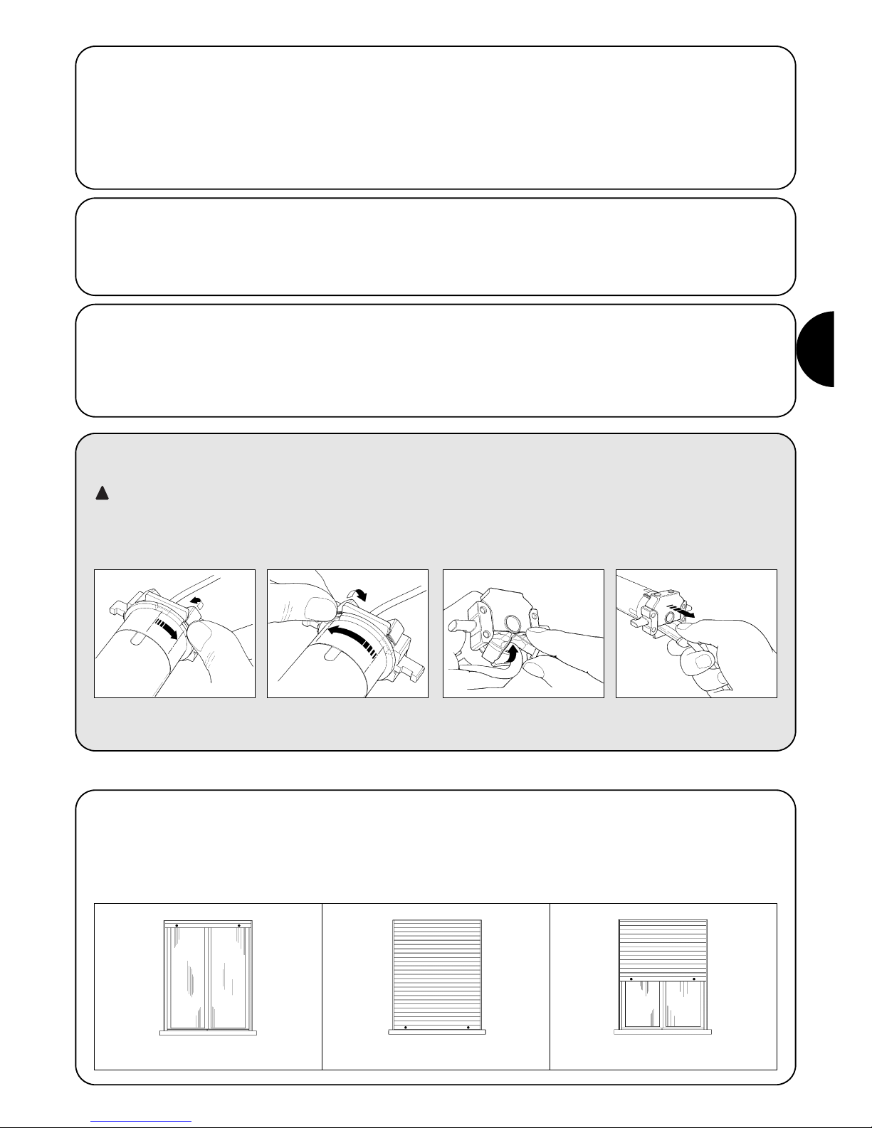
D
27
2.2) Verbinder und Versorgungskabel (dieser Punkt bezieht sich nur auf die Version NEOMAT A und ist für technisches Kun-
dendienstpersonal bestimmt)
ACHTUNG: falls das Versorgungskabel beschädigt sein sollte, muss es mit einem gleichen ersetzt werden, das beim
Hersteller oder dessen Kundendienst erhältlich ist.
Falls der Motor vom Versorgungskabel abgetrennt werden muss, ist wie in den folgenden Abbildungen gezeigt vorzugehen:
!
Die Rohrmotoren der Serie NEOMAT A verfügen über ein elektronisches Endschaltersystem; die elektronische Steuerung unterbricht
die Bewegung, wenn die Jalousie die programmierten Öffnungsund Schließpositionen erreicht. Diese Positionen werden über Programmierung gespeichert; die Programmierung muss direkt mit
installiertem Motor und ganz montierter Jalousie gemacht werden.
Der Motor kann auch gesteuert werden, wenn die Positionen “0“
(Jalousie geöffnet) und “1“ (Jalousie geschlossen) noch nicht programmiert worden sind, die Bewegung wird dann aber nur erfolgen,
solange der Steuerbefehl gegeben wird. Es kann auch eine Zwischenposition (Pos. “I”) für die Teilöffnung der Jalousie programmiert
werden.
Die Nutmutter drehen, bis sich die
Abkantung auf einem der Einspannzähne befindet, dann ausspannen.
Den Vorgang am anderen Zahn
wiederholen
Das Kabel nach innen biegen und
den Schutz entfernen, indem er
behutsam nach außen gedreht wird
Den Verbinder herausziehen
3) Einstellungen
Jalousie geöffnet (Pos. “0”) Jalousie geschlossen (Pos.”1”) Zwischenposition (“I”)
2.1.2) Eingang “TTBUS”:
Der “TTBUS” ist ein Bus, der entwickelt wurde, um die Steuerungen
der Motoren für Markisen und Jalousien kontrollieren zu können. Der
Bus sieht die Möglichkeit vor, separat bis zu 100 Steuerungen zu
kontrollieren, indem diese mit nur 2 Leitern (gemeinsamer Leiter und
“TTBUS”) parallelgeschaltet werden. Weitere Auskünfte sind in den
Anleitungen der Fernsteuerungen per “TTBUS” enthalten.
2.1.3) Wetterwächter:
Am Eingang “Wetterwächter” kann ein einfacher Windsensor (Windwächter) oder ein spezieller Wind-Sonne-Regenwächter zwischen
gemeinsamem Leiter (schwarzem Leiter) und Eingang Wetterwächter (orangem Leiter) angeschlossen werden. An demselben Sensor
können bis zu 5 parallelgeschaltete Steuerungen angeschlossen
werden, wobei die Polung der Signale zu beachten ist (an allen
Motoren muss der schwarze Leiter mit dem schwarzen und der
orangefarbige mit dem orangefarbigen verbunden werden).
2.1.1) Eingang “Schrittbetrieb”:
Um die Automatisierung manuell zu steuern, kann eine einfache
Taste (zwischen gemeinsamem Leiter und Eingang Schrittbetrieb)
angeschlossen werden. Der Betrieb erfolgt mit dieser Sequenz:
Anstieg- Stop – Abstieg – Stop.
Wird die Taste länger als 3 Sekunden (aber kürzer als 10) gedrückt
gehalten, so aktiviert sich immer eine Aufwärtsbewegung (wie durch
Druck auf die Taste ▲ der Funksteuerungen). Wird die Taste länger
als 10 Sekunden gedrückt, so aktiviert sich immer eine Abwärtsbewegung (wie durch Druck auf Taste ▼). Diese Besonderheit kann
nützlich sein, um mehrere Motoren, unabhängig von ihrem Betriebsstatus, auf dieselbe Bewegung zu “synchronisieren”.

28
Die Programmierung ist in 3 Abschnitte unterteilt:
1. Speicherung der Sender
2. Programmierung der Positionen “0” und “1”
3. Programmierung von Zusatzfunktionen
ACHTUNG: Alle Speichersequenzen der Sender und
der Programmierungen müssen innerhalb der vorgesehenen Zeitgrenzen ausgeführt werden
• An Funksteuerungen, die mehrere “Gruppen” vorsehen,
muss vor der Speicherung die Gruppe gewählt werden,
mit welcher der Motor kombiniert werden soll.
• Die Programmierung per Funk kann an allen Motoren
erfolgen, die sich in der Reichweite des Senders befinden, daher sollte nur der betreffende Motor gespeist
sein.
4) Programmierung
4.1) Speicherung der Sender
Jede Funksteuerung wird vom Empfänger, der in die NEOMAT A Steuerung eingebaut ist, durch einen “Code” erkannt, der für jede Funksteuerung verschieden ist. Daher ist eine „Speicherungsphase“ erforderlich, in der man die Steuerung auf die Erkennung jeder einzelnen
Funksteuerung vorbereitet.
Ist kein Code im Speicher enthalten, so kann die erste Funksteuerung wie folgt eingegeben werden:
!
1. Sobald die Steuerung mit Spannung versorgt ist, wird man 2 lange Bieptöne (biiip) hören
2. Innerhalb von ■ Sekunden auf Taste 5 des zu speichernden Senders drücken und diese
gedrückt halten (ca. 3 Sekunden lang) 3s
3. Die Taste ■ loslassen, wenn man den ersten der 3 Bieptöne hört, welche die
Speicherung bestätigen
Anmerkung: Enthält die Steuerung bereits Codes, wird man beim Einschalten 2 kurze Bieptöne (bip) hören;
in diesem Fall muss auf eine andere Art gespeichert werden (Tabelle “A2”)
Tabelle “A1” Speicherung des ersten Senders (Abb. 7) Beispiel
1. Auf Taste ■ des neuen Senders drücken, bis man einen Biepton hört (nach ca. 5 Sekunden)
neuen 5s
2. Langsam drei Mal auf Taste ■ eines bereits aktivierten Senders (alt) drücken
eines X3
3. Nochmals auf Taste ■ des neuen Senders drücken.
neuen
4. Am Ende werden 3 Bieptöne melden, dass der neue Sender korrekt gespeichert worden ist.
Anmerkung: Ist der Speicher voll (14 Codes), werden 6 Bieptöne melden, dass der Sender nicht gespeichert werden kann.
Tabelle “A2” Speicherung weiterer Sender (Abb. 8) Beispiel
Wenn ein oder mehrere Sender bereits gespeichert sind, können andere wie folgt aktiviert werden:
4.2) Programmierung der Positionen “0” und “1”
Wenn Jalousien automatisiert werden, gibt es gewöhnlich die 3 folgenden Fälle, die durch das Vorhandensein oder nicht von Elementen
bedingt sind, die den Lauf der Jalousie blockieren: “Endlaufstopfen” im Anstieg (sie begrenzen die maximale Öffnung) und/oder “Einbruchsicherungsfedern” (die verhindern, dass die Jalousie von Hand gehoben werden kann, wenn sie ganz geschlossen ist).
Je nachdem, ob diese mechanischen Endlaufgrenzen (Stopfen und/oder Federn) vorhanden sind, kann die Endlaufprogrammierung unterschiedlich erfolgen:
Manuelle Endlaufprogrammierung (Stopfen oder Einbruchsicherungsfedern sind nicht erforderlich)
Halbautomatische Endlaufprogrammierung (Die Stopfen in Anstieg sind erforderlich).
Automatische Endlaufprogrammierung (Die Stopfen in Anstieg sowie die Einbruchsicherungsfedern in Abstieg sind erforderlich).
Zur Programmierung der Positionen muss eine bereits gespeicherte Fernbedienung verwendet werden. Solange die Positionen “0” und “1”
nicht gültig in der Steuerung gespeichert sind, werden die Bewegungen nur erfolgen, solange der Steuerbefehl gegeben ist. Anfänglich ist
der Drehsinn des Motors nicht festgelegt, aber nach Beendigung der Programmierung wird der Motordrehsinn den Fernbedienungstasten
automatisch zugeteilt.

D
29
1. Auf Taste ▲ oder ▼ einer gespeicherten Fernbedienung drücken und gedrückt halten,
bis die gewünschte Öffnungsposition erreicht ist.
2. Die Sendertaste ■ gedrückt halten, bis man einen Biepton hört (nach ca. 5 Sekunden).
5s
3. Loslassen und noch mal 5 Sekunden lang auf die Taste ■ drücken, bis man 4 Bieptöne
kurz aufeinander hört. 5s
4. Auf Taste ▲ drücken, bis 3 Bieptöne und eine kurze Bewegung melden, dass die
Öffnungsposition gespeichert ist.
5. Auf Taste ▲ oder ▼ der gespeicherten Fernbedienung drücken und gedrückt halten,
bis die gewünschte Schließposition erreicht ist.
6. Die Sendertaste ■ gedrückt halten, bis man einen Biepton hört (nach ca. 5 Sekunden).
5s
7. Loslassen und noch mal 5 Sekunden lang auf die Taste ■ drücken, bis man 4 Bieptöne
kurz aufeinander hört. 5s
8. Auf Taste ▼ drücken, bis 3 Bieptöne und eine kurze Bewegung melden, dass die
Schließposition gespeichert ist.
Anmerkung: Nun wird der Anstieg mit Taste ▲ erfolgen, und der Abstieg mit Taste ▼.
Die An- und Abstiegsbewegungen werden an den programmierten Positionen gestoppt.
Tabelle “A3” MANUELLE Programmierung der Positionen “0” und “1” (Abb. 9) Beispiel
1. Auf Taste ▲ oder ▼ einer gespeicherten Fernbedienung drücken und gedrückt halten,
bis die Jalousie ganz geöffnet ist und der Motor automatisch an den Anstiegsstopfen anhält.
2. Auf Taste ▼ drücken und diese gedrückt halten, so dass die Jalousie nach unten geht.
3. Taste ▼ loslassen, wenn die Jalousie die gewünschte Position (“1”) erreicht
5s
4. Die Sendertaste ■ gedrückt halten, bis man einen Biepton hört (nach ca. 5 Sekunden).
5s
5. Loslassen und noch mal 5 Sekunden lang auf die Taste ■ drücken, bis man 4 Bieptöne
kurz aufeinander hört. 5s
6. Auf Taste ▼ drücken, bis 3 Bieptöne und eine kurze Bewegung melden, dass die
Schließposition gespeichert ist.
Anmerkung: Nun wird der Anstieg mit Taste ▲ erfolgen, und der Abstieg mit Taste ▼.
In Anstieg wird die Jalousie an den Stopfen anhalten, in Abstieg an der programmierten Position.
Tabelle “A4” HALBAUTOMATISCHE Programmierung der Positionen “0” und “1”(Abb. 10) Beispiel
1. Prüfen, ob sich die Jalousie auf ca. Hälfte Lauf befindet; die Jalousie ggf. mit den Tasten
▲ und ▼ einer bereits gespeicherten Fernbedienung auf Laufhälfte verschieben.
2. Auf Taste ■ eines bereits gespeicherten Senders drücken und gedrückt halten, bis man
einen Biepton hört (nach ca. 5 Sekunden). 5s
3. Loslassen und noch mal 5 Sekunden lang auf die Taste ■ drücken, bis man 4 Bieptöne
kurz aufeinander hört. 5s
4. Loslassen und noch mal auf die Taste ■ drücken, bis man den ersten der 2 langen
Bieptöne hört
5. Die Jalousie muss sich nach oben bewegen; falls die Bewegung nach unten ist, muss Taste
▲ oder ▼ gedrückt werden, damit sich die Jalousie nach oben bewegt.
6. Das Verfahren ist ab jetzt automatisch:
zuerst wird die Position “0” an den Stopfen in Öffnung gefunden,
dann die Position “1”an den Einbruchsicherungsfedern in Schließung.
7. Das Verfahren endet mit ganz geschlossener Jalousie und mit 3 Bieptönen.
Anmerkung: Nun wird der Anstieg mit Taste ▲ erfolgen, und der Abstieg mit Taste ▼.
Die Bewegungen in An- und Abstieg werden kurz vor den festgelegten Grenzen gestoppt.
Tabelle “A5” AUTOMATISCHE Programmierung der Positionen “0” und “1” (Abb. 11) Beispiel

30
4.3) Programmierung von Zusatzfunktionen
Zusatzfunktionen können erst programmiert werden, nachdem die Programmierung der Positionen “0” und “1” beendet ist.
Speicherung der Zwischenposition “I”
Falls eine Zwischenposition “I” programmiert ist, kann die Jalousie durch gleichzeitigen Druck auf die 2 Sendertasten ▼ ▲ in die programmierte Position bewegt werden.
Zur Programmierung der Zwischenposition muss folgendes Verfahren durchgeführt werden:
1. Die Jalousie mit den Tasten ▲ ■ ▼ einer Fernbedienung dorthin verschieben,
wo die Position “I” sein soll.
2. Die Taste ■ gedrückt halten, bis man einen Biepton hört (nach ca. 5 Sekunden).
5s
3. Loslassen und noch mal 5 Sekunden lang auf die Taste ■ drücken, bis man 4 Bieptöne
kurz aufeinander hört. 5s
4. Gleichzeitig auf die Tasten ▼ ▲ drücken, bis die Speicherung des Maßes durch 3 Bieptöne
bestätigt wird.
Tabelle “A6” Programmierung der Zwischenposition “I” (Abb. 12) Beispiel
4.4) Änderung der gespeicherten Positionen
Um gespeicherte Positionen ändern zu können, müssen sie zuerst gelöscht werden; erst dann können die neuen Positionen programmiert werden.
Sollte es nötig sein, alle Daten im Speicher der NEOMAT Steuerung zu löschen, kann das folgende Verfahren durchgeführt werden.
Das Löschen des Speichers ist möglich:
• mit einem nicht gespeicherten Sender, wobei man bei Punkt A beginnt.
• mit einem bereits gespeicherten Sender, wobei man das Verfahren ab Punkt Nr. 1 beginnt
Gelöscht werden können:
• nur die Codes der Sender, wobei man das Verfahren an Punkt Nr. 4 beendet
• alle Daten (Sendercodes, Positionen, Ansprechstufe des Wind- und Sonnewächters, TTBUS-Adresse, usw.), indem das ganze Verfahren
durchgeführt wird.
1. Die Taste ■ eines bereits gespeicherten Senders gedrückt halten, bis man einen Biepton
hört (nach ca. 5 Sekunden) 5s
2. Loslassen und noch mal 5 Sekunden lang auf die Taste ■ drücken, bis man 4 Bieptöne
kurz aufeinander hört. 5s
3. Gleichzeitig auf die Tasten ▲ ▼ drücken, bis das Löschen der Zwischenposition durch 5.
Bieptöne bestätigt wird
Nun kann die neue Zwischenposition programmiert werden (Tabelle “A6”)
Tabelle “A7” Löschen der Zwischenposition “I” (Abb. 12) Beispiel
1. Die Taste ■ eines bereits gespeicherten Senders gedrückt halten, bis man einen Biepton
hört (nach ca. 5 Sekunden) 5s
2. Loslassen und noch mal 5 Sekunden lang auf die Taste ■ drücken, bis man 4 Bieptöne
kurz aufeinander hört. 5s
3. Auf Taste ▲ drücken (falls die automatische oder die manuelle Programmierung durchgeführt
worden ist) oder auf Taste ▼ drücken (im Falle der halbautomatischen Programmierung), bis
das Löschen der Positionen “0” und “1” durch 5 Bieptöne bestätigt wird.
ACHTUNG: Nach dem Löschen der Positionen “0” und “1” wird sich die Jalousie nur bewegen, solange der Steuerbefehl gegeben wird,
und neue Positionen müssen gespeichert werden. (Tabellen “A3”, “A4”, “A5”).
Tabelle “A8” Löschen der Positionen “0” und “1” (Abb. 13) Beispiel
A. Den Eingang Schrittbetrieb mit nicht gespeistem Motor aktivieren (den schwarz-weißen
Draht anschließen) und bis zum Ende des Verfahrens aktiviert halten
B. Den Motor speisen und warten, bis man die 2 ersten Bieptöne hört.
1. Die Taste ■ eines bereits gespeicherten Senders gedrückt halten, bis man einen Biepton hört
(nach ca. 5 Sekunden) 5s
2. Die Taste ▲ des Senders gedrückt halten, bis man 3 Bieptöne hört; die Taste ▲ genau
während des dritten Bieptons loslassen. 5s
3. Die Taste ■ des Senders gedrückt halten, bis man 3 Bieptöne hört; die Taste ■ genau
während des dritten Bieptons loslassen.
4. Die Taste ▼ des Senders gedrückt halten, bis man 3 Bieptöne hört; die Taste ▼ genau
während des dritten Bieptons loslassen.
5. Falls man alle Daten löschen will, innerhalb von 2 Sekunden beide Tasten ▲ und ▼ innerhalb
gleichzeitig drücken, dann loslassen. von 2s
Nach ein paar Sekunden werden 5 Bieptöne melden, dass alle Codes aus dem Speicher gelöscht worden sind.
Tabelle “A9” Löschen des Speichers (Abb. 14) Beispiel
➨
➨
➨
PP
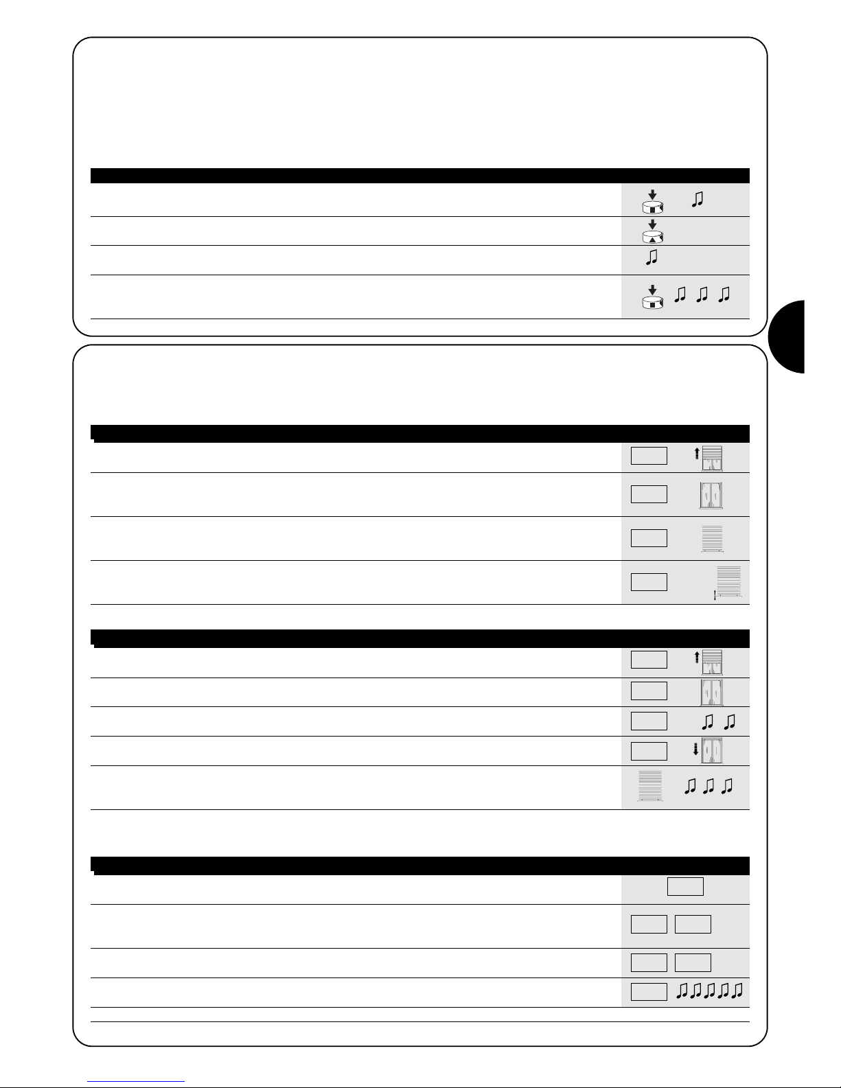
D
31
1. Auf Taste ■ eines bereits gespeicherten Senders drücken, bis man einen Biepton hört
(nach ca. 5 Sekunden) 5s
2. Langsam auf Taste ▲ drücken, 1-,2- oder 3-mal, je nach gewünschter Stufe
3. Nach kurzer Zeit wird man so viele Bieptöne hören, wie die Zahl der gewünschten Stufe ist.
4. Auf Taste ■ drücken, um zu bestätigen; 3 Bieptöne werden die Neuprogrammierung anzeigen.
Um das Verfahren ohne Änderung der vorherigen Stufe abzubrechen, mindestens 5 Sekunden
lang ohne zu bestätigen warten.
Tabelle “A10” Änderung der Ansprechstufe des “Windwächters” (Abb.15) Beispiel
4.5) Programmierung der Wetterwächter
Wird am Eingang “Sensoren” ein Windwächter angeschlossen, so kann man zwischen 3 möglichen Ansprechstufen wählen (1. = 15Km/h,
2. = 30Km/h und 3. = 45 Km/h, falls der Wächter „VOLO“ benutzt wird). Ursprünglich ist Stufe Nr. 2 eingestellt. Wenn die Stufe länger als 3
Sekunden überschritten wird, aktiviert sich ein Befehl wie durch Taste ▲ , und jede Bewegung wird blockiert, bis der Wind mindestens eine
Minute lang wieder unter die programmierte Stufe zurückgeht.
Zur Änderung der programmierten Stufe::
X1= 15 km/h
X2= 30 km/h
X3= 45 km/h
X1= 15 km/h
X2= 30 km/h
X3= 45 km/h
1. Den Steuerbefehl Schrittbetrieb geben; falls sich die Jalousie abwärts bewegt, die Taste
loslassen und den Vorgang wiederholen.
2. Den Steuerbefehl Schrittbetrieb solange geben, bis der Motor automatisch anhält, weil die
ganz geöffnete Jalousie auf die Stopfen gestoßen ist (Position “0”).
Dann die Taste loslassen.
3. Die Jalousie mit Hilfe des Steuerbefehls Schrittbetrieb während der Abwärtsbewegung am
gewünschten Schließpunkt (Position “1”) anhalten, so dass der nächste Steuerbefehl den
Anstieg der Jalousie verursacht.
4. Zweimal nacheinander (innerhalb von 2 Sekunden) den Steuerbefehl Schrittbetrieb geben und
den zweiten Befehl mindestens 5 Sekunden lang aktiviert halten (Motor steht), bis 3 Bieptöne
und eine kurze Auf- und Abwärtsbewegung die Speicherung der Position bestätigen werden. X2(X5s)
Tabelle “A11” Programmierung der Positionen “0” und “1” mit HALBAUTOMATISCHER Suche Beispiel
4.6) Programmierung der Positionen ohne Sender
Obgleich auf weniger einfache Weise, können die Laufgrenzen und die Positionen “0” und “1” auch ohne Fernbedienung nur durch Verwendung des Eingangs Schrittbetrieb programmiert werden.
In diesem Fall sind nur die HALBAUTOMATISCHE und die AUTOMATISCHE Programmierung möglich.
PP
PP
PP
PP
1. Den Steuerbefehl Schrittbetrieb geben; falls sich die Jalousie abwärts bewegt, die
Taste loslassen und den Vorgang wiederholen.
2. Den Steuerbefehl Schrittbetrieb solange geben, bis der Motor automatisch anhält, weil die
ganz geöffnete Jalousie auf die Stopfen gestoßen ist (Position “0”).
3. Den Steuerbefehl weitere 5 Sekunden lang geben, bis man 2 Bieptöne hört, dann die Taste
loslassen. X5s
4. Die Jalousie wird sich abwärts bewegen, um Position “1” zu suchen. Das Verfahren kann
durch die erneute Aktivierung des Befehls Schrittbetrieb unterbrochen werden.
5. Wenn die Jalousie die Position ganz geschlossen an den Einbruchsicherungsfedern erreicht
hat, wird sie anhalten und die erfolgte Programmierung der Positionen “0” und “1” wird durch
drei Bieptöne bestätigt.
Anmerkung: Die Zwischenposition kann mit Hilfe des Steuerbefehls Schrittbetrieb nicht gespeichert werden.
Tabelle “A12” Programmierung der Positionen “0” und “1” mit AUTOMATISCHER Suche Beispiel
PP
PP
PP
PP
Wenn man die Positionen ändern will, müssen alle durchgeführten Einstellungen gelöscht und das ganze Verfahren muss wiederholt werden.
1. Den Steuerbefehl Schrittbetrieb geben; falls sich die Jalousie in Anstieg bewegt, die Taste
loslassen und den Vorgang wiederholen. 3s
2.
Den Steuerbefehl weiter geben, bis nach ca. 3 Sekunden eine Anstiegsbewegung beginnt; den
Steuerbefehl Schrittbetrieb 2 Mal nacheinander geben (innerhalb von 2 Sekunden) und das zweite
Mal die Taste gedrückt halten, um die Jalousie zu stoppen und eine Abstiegsbewegung zu beginnen.
3s
3. Den vorherigen Punkt noch 3 Mal wiederholen.
Beim 3. Versuch wird die Anstiegsbewegung nicht mehr erfolgen. X3
4. Den Steuerbefehl Schrittbetrieb weitere 10 Sekunden lang geben, bis durch 5 Bieptöne
gemeldet wird, dass alle Positionen gelöscht worden sind.
Anmerkung: Nach dem Löschen der Positionen wird sich die Jalousie nur bewegen, wenn und solange ein Steuerbefehl gegeben wird.
Tabelle “A13” Löschen der Positionen “0” und “1” mit Hilfe des Steuerbefehls Schrittbetrieb Beispiel
PP
PP PP
PPPPPP

32
Nach seiner Versorgung gibt der Motor die 2 Bieptöne
nicht ab und der Eingang Schrittbetrieb verursacht keine
Bewegung.
Kontrollieren, ob der Motor mit der vorgesehenen Netzspannung
gespeist ist, falls ja, liegt wahrscheinlich ein schwerer Defekt vor und
der Motor muss ausgewechselt werden..
Nach einem Befehl per Funk hört man 6 Bieptöne, aber
keine Bewegung erfolgt. Die Funksteuerung ist nicht synchroni-
siert, der Sender muss neu gespeichert werden.
Nach einem Befehl hört man 10 Bieptöne, dann erfolgt die
Bewegung.
Die Selbstdiagnose der gespeicherten Parameter hat eine Störung
festgestellt (Positionen, TTBUS-Adresse, Stufe des Wind-/Sonnenwächters, Bewegungsrichtung sind unkorrekt). Programmierungen
kontrollieren und ggf. wiederholen.
Nach einem Steuerbefehl bewegt sich der Motor nicht.
• Der Wärmeschutz könnte ausgelöst sein, in diesem Fall genügt
es zu warten, bis sich der Motor abgekühlt hat
• Falls ein Windwächter angeschlossen ist, könnte die eingestellte
Schwelle überschritten worden sein
• Andernfalls den Motor ausschalten und wieder einschalten; wenn
man keine 2 Bieptöne hört, liegt wahrscheinlich ein schwerer
Defekt vor und der Motor muss ausgewechselt werden.
In Anstieg, bevor die vorgesehene Position (Pos. “0”, Pos.
“I”) erreicht wird, hält der Motor an und versucht dann 3
Mal, wieder zu starten. Kann normal sein: wenn die Positionen
“0” ”1” auf HALBAUTOMATISCHE Weise programmiert worden sind:
wenn in Anstieg eine zu große Kraftanstrengung bemerkt wird, wird
der Motor ca. 1 Sekunde lang abgeschaltet, dann wird versucht, die
Bewegung zu beenden; prüfen, ob die Bewegung durch etwas
behindert ist.
In An- oder Abstieg, bevor die vorgesehene Position (Pos.
“0”, Pos. “I”) erreicht wird, hält der Motor an.
Kann normal sein: wenn eine zu große Kraftanstrengung bemerkt
wird, wird der Motor abgeschaltet; prüfen, ob die Bewegung durch
etwas behindert ist.
Der Motor bewegt sich nur infolge eines Steuerbefehls.
Wenn die Positionen “0” und “1” nicht programmiert worden sind, so
erfolgt die durch den Motor verursachte Bewegung in An- und
Abstieg nur infolge eines Steuerbefehls. Die Positionen “0” und “1”
programmieren.
Die Positionen “0” und “1” sind programmiert, aber die
Abstiegsbewegung erfolgt nur infolge eines Steuerbefehls. Die Selbstdiagnose der gespeicherten Parameter hat eine
Störung in der Position des Motors festgestellt. Einen Steuerbefehl
für den Anstieg der Jalousie geben und warten, bis die Position “0“
erreicht wird.
5) Was tun, wenn... kleiner Leitfaden, wenn etwas nicht funktioniert!
6) Technische Merkmale
Rohrmotoren Serie NEOMAT A
Versorgungsspannung und Frequenz : siehe Technische Daten auf dem Etikett eines jeden Modells
Stromaufnahme und Leistung : siehe Technische Daten auf dem Etikett eines jeden Modells
Drehmoment und Geschwindigkeit : siehe Technische Daten auf dem Etikett eines jeden Modells
Dauerbetriebszeit : max. 4 Minuten
Arbeitszyklus : max. 20%
Schutzart : IP 44
Betriebstemperatur : -10 ÷ 70 °C
Präzision (Auflösung) des elektronischen : Endschalters größer als 0,55° (hängt von der NEOMAT Version ab)
Elektronische Steuerung
Spannung der Signale : (Schrittbetrieb, Wetterwächter) ca. 24Vdc
Stufen des Windwächters : ca. 30 oder 15 oder 45 Km/h (mit Windwächter “VOLO”)
Kabellänge der Signale (Schrittbetrieb, Wetterwächter) : max. 30m, falls in der Nähe anderer Kabel, andernfalls 100m
Funkempfänger
Frequenz : 433.92 MHz
Codierung : 52 Bit Rolling Code FLOR
Reichweite der Sender ERGO und PLANO : ca. 200 m auf freiem Feld, 35 m in Gebäuden.
Nice S.p.a. behält sich das Recht vor, jederzeit Änderungen am Produkt anzubringen

D
33

34
Advertencias:
Los motores serie “NEOMAT A” han sido realizados para automatizar el
movimiento de persianas; todo otro empleo debe considerarse impropio
y está prohibido. Los motores han sido diseñados para uso residencial y
se ha previsto un tiempo de trabajo continuo máximo de 4 minutos con
un ciclo del 20%. Al elegir el tipo de motor de acuerdo con su aplicación,
deberán considerarse el par nominal y el tiempo de funcionamiento indicados en la placa de características. El diámetro mínimo del tubo en el
que se puede instalar el motor es 40mm para NEOMAT SA, 52mm para
NEOMAT MA y 70mm para NEOMAT LA. La instalación debe ser hecha
por personal técnico respetando las normas de seguridad. En los aparatos para uso en exteriores, el cable de alimentación de PVC debe insta-
larse adentro de un tubo de protección. Procure que el motor tubular no
sufra aplastamientos, golpes, caídas y que no tenga contacto con líquidos de ningún tipo; no perfore ni aplique tornillos a lo largo del motor
tubular (fig. 1). Diríjase a personal técnico capacitado para el mantenimiento o las reparaciones.
Atención: algunas etapas de la programación pueden aprovechar los
fines de carrera mecánicos de la persiana (topes o dispositivos de seguridad de enganche al eje). En este caso es indispensable escoger el motor
con el par más adecuado para la aplicación, considerando el peso efectivo de la persiana evitando los motores demasiado potentes.
Los motores tubulares NEOMAT SA Ø35mm, NEOMAT MA Ø45
mm (fig. 2) y NEOMAT LA Ø58mm tienen una central electrónica con
radiorreceptor incorporado que trabaja a una frecuencia de 433.92
MHz con tecnología rolling code (código alternante), para garantizar
niveles de seguridad elevados. Para cada motor es posible memorizar hasta 14 radiomandos de la serie "ERGO" y "PLANO" (figs. 3 y
4) o “VOLO S RADIO”. La central incorporada en el motor dispone
de un sistema de fin de carrera electrónico de alta precisión, que
puede detectar constantemente la posición de la persiana. Con una
operación de programación se memorizan los límites del movimiento, es decir persiana cerrada y persiana abierta (más una posible
posición intermedia); después de cada mando el movimiento se
detendrá automáticamente al alcanzar esas posiciones.
La central también consigue detectar variaciones bruscas y esfuerzos
del motor interrumpiendo de inmediato el movimiento, esta característica también se utiliza para programar automáticamente los límites
de maniobra si la persiana dispone de topes de fin de carrera superiores y de dispositivos de seguridad de enganche al eje.
La programación de los límites de movimiento y de algunas funciones adicionales es ejecutada por los radiomandos, un “Tono de aviso” (Bip) le guiará por las diferentes etapas. También es posible
accionar los motores con un botón exterior (con función Paso a
Paso), o bien por medio de Bus "TTBUS". Los sensores opcionales
de viento, sol y lluvia pueden activar automáticamente el sistema
cuando las condiciones climáticas así lo requieren.
1) Descripción del producto
2) Instalación
Prepare el motor con la siguiente secuencia de operaciones (fig. 4):
1. Introduzca el casquillo loco (E) en el motor (A) hasta que entre en
el. anillo loco (F) correspondiente.
2. Introduzca el anillo de arrastre (D) en el árbol del motor. En NEO-
MAT SA el anillo se fija automáticamente a presión
3. En NEOMAT MA fije el anillo de arrastre con la arandela seeger a
presión
Figura 4
A:
Motor tubular NEOMAT A
B:
Clips o pasadores hendidos para fijación
C:
Soporte y distanciador
D:
Anillo de arrastre
E:
Casquillo loco
F:
Anillo loco
NEOMAT A es un producto de Motus Motus S.p.a. (TV) I. ERGO, PLANO, VOLO son productos de Nice S.p.a.(TV) I. Motus s.r.l. es una sociedad del grupo Nice S.p.a.
Introduzca el motor ensamblado de esta manera en el tubo en que
se enrolla la persiana hasta tocar el extremo del casquillo loco (E).
Fije el tubo con el anillo de arrastre (D) mediante los tornillos M4x10
para que el motor no se desplace ni se deslice axialmente (fig. 5) Por
último, bloquee la cabeza del motor al soporte respectivo (C) con el
distanciador, por medio de los clips o del pasador hendido (B).
2.1) Conexiones eléctricas
ATENCIÓN: en las conexiones del motor hay que prever un dispositivo omnipolar de desconexión de la red
eléctrica con distancia entre los contactos de 3 mm como
mínimo (interruptor o enchufe y tomacorriente, etc.).
ATENCIÓN: Respete escrupulosamente las conexiones
previstas; si tuviera dudas no pruebe inútilmente, sino que
consulte las fichas técnicas disponibles también en el
sitio “www.niceforyou.com”.
Una conexión incorrecta puede provocar averías o situaciones peligrosas.
El cable para las conexiones eléctricas del motor NEOMAT A dispone de 6 conductores de conexión:
• Línea de alimentación de la red eléctrica: Fase, Neutro y Tierra
•Señales de mando de bajísima tensión (SELV) Paso a Paso o Bus
"TTBUS" y sensores climáticos
!
!
Marrón = Fase
Azul = Neutro
Amarillo/Verde = Tierra
Negro = Común (0V)
Blanco = Paso a paso + "TTBUS"
Naranja = Sensores climáticos
Etiqueta
amarilla
Etiqueta
verde
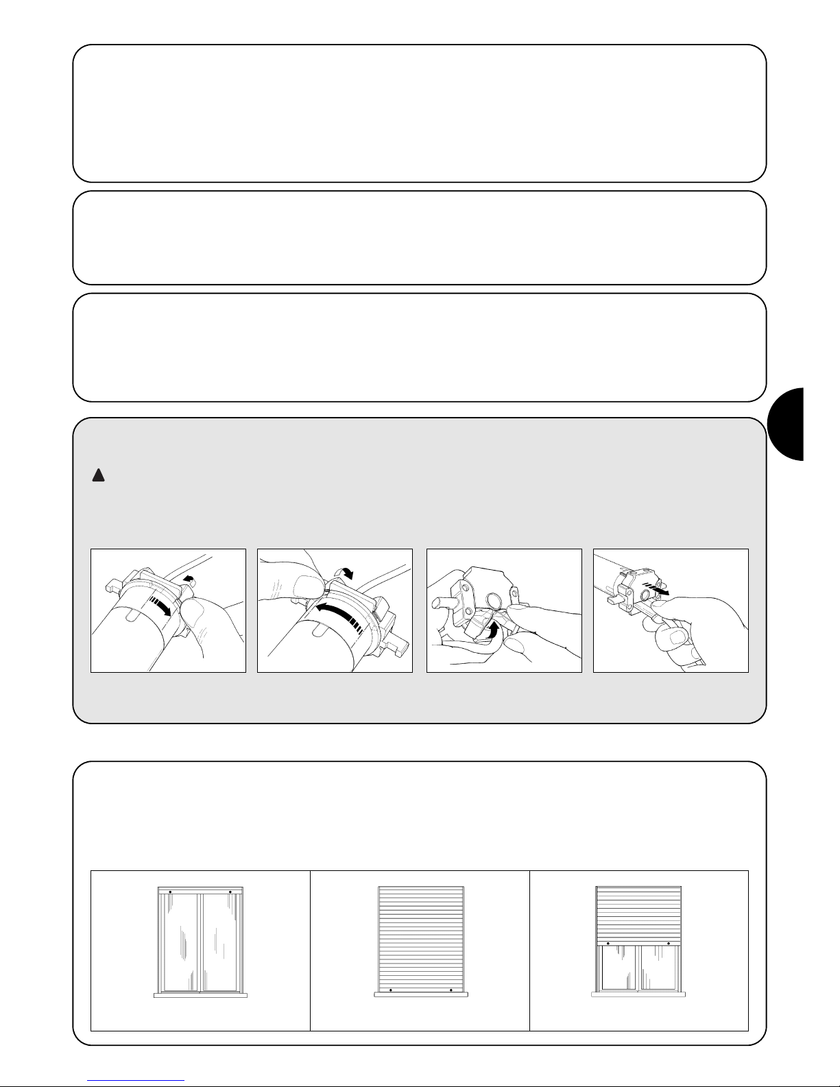
E
35
2.2) Conector y cable de alimentación (este capítulo se refiere sólo a la versión NEOMAT A y está dedicado exclusivamente al
personal técnico del servicio de asistencia).
ATENCIÓN: si el cable de alimentación estuviera arruinado sustitúyalo con uno idéntico que se puede pedir al fabri-
cante o a su servicio de asistencia.
De ser necesario, desconecte el motor del cable de alimentación, siguiendo las instrucciones indicadas en las siguientes figuras:
!
Los motores tubulares serie NEOMAT A disponen de un sistema de
fin de carrera electrónico; la central electrónica interrumpe el movimiento cuando la persiana llega a las posiciones de cierre y de apertura programadas. Dichas posiciones se memorizan con una programación oportuna que debe hacerse directamente con el motor
instalado y con la persiana completamente montada.
Si aún no fueron memorizadas las posiciones “0” (persiana abierta)
y “1” (persiana cerrada) es posible accionar igualmente el motor,
pero el movimiento se ejecutará sólo en modo manual. También es
posible programar una posición intermedia (Pos. “I”) para abrir la
persiana parcialmente.
Gire la rosca hasta hacer coincidir la
ranura con uno de los dientes de
enganche; después desenganche.
Repita la operación para el otro
diente.
Pliegue el cable hacia adentro y
quite la protección girándola con
delicadeza hacia afuera.
Extraiga el conector tirando de él
3) Regulaciones
Persiana abierta (Pos. “0”) Persiana cerrada (Pos. “1”) Posición intermedia (“I”)
2.1.2) Entrada "TTBUS":
El "TTBUS" es un Bus desarrollado para poder controlar las centrales de mando de los motores para toldos y persianas. El Bus ofrece
la posibilidad de controlar individualmente hasta 100 centrales,
conectándolas simplemente en paralelo con 2 conductores solos
(Común y "TTBUS"). Mayores informaciones se encuentran en las
instrucciones de los mandos a distancia por "TTBUS".
2.1.3) Sensores climáticos:
En la entrada "Sensores climáticos" entre Común (conductor negro)
y la entrada Sensores climáticos (conductor naranja) puede conectarse un sencillo sensor de viento (anemómetro), o bien un sensor
especial de viento-sol-lluvia.
A un mismo sensor se pueden conectar hasta 5 centrales en paralelo, respetando la polaridad de las señales (en todo los motores, el
conductor negro se conecta al negro y el naranja al naranja).
2.1.1) Entrada "Paso a Paso":
Para accionar la automatización en modo manual, es posible conectar un botón (entre Común y la entrada Paso a Paso). El modo de
funcionamiento sigue la secuencia: subida-parada-bajada-parada.
Si se mantiene apretado el botón durante más de 3 segundos (pero
menos de 10 seg.) siempre se activa una maniobra de subida (la que
corresponde al botón ▲ de los radiomandos).
Si se mantiene apretado el botón durante más de 10 segundos,
siempre se activa una maniobra de bajada (correspondiente al botón
▼) Esta solución puede ser útil para "sincronizar" varios motores
hacia la misma maniobra, independientemente del estado en que se
encuentren.

36
La programación se divide en 3 partes:
1. Memorización de los transmisores.
2. Programación de las posiciones “0” y “1”
3. Programaciones opcionales
ATENCIÓN: Todas las secuencias de memorización de
los transmisores y de las programaciones de los parámetros son por tiempo, es decir que tienen que ser efectuadas dentro de los límites de tiempo previstos.
•Con radiomandos que prevean varios “grupos”, antes de
proceder con la memorización hay que seleccionar el
grupo al que asociar el motor.
• La programación por radio se puede realizar en todos
los motores que se encuentren en el radio de alcance
del transmisor, por lo que es oportuno mantener alimentado sólo aquel que debe ser programado.
4) Programación
4.1) Memorización de los transmisores
Cada radiomando es reconocido por el receptor incorporado en la central de NEOMAT A por medio de un “código” diferente de cualquier otro.
Por eso es necesaria una etapa de “memorización” con la que se prepara a la central para que reconozca cada uno de los radiomandos.
Cuando en la memoria no hay ningún código, se puede proceder a memorizar el primer radiomando de la siguiente manera:
!
1. Ni bien se conecta la alimentación a la central, se oirán 2 tonos de aviso largos (biiip).
2. Antes de transcurridos 5 segundos, presione y mantenga apretado el botón ■ del transmisor
a memorizar (durante alrededor de 3 segundos) 3s
3. Suelte el botón ■ cuando oiga el primero de los 3 tonos de aviso que confirman la
memorización
Nota: Si la central ya contiene códigos, en el momento del encendido se oirán 2 tonos de aviso cortos (bip) y no se podrá proceder como
descrito, sino que habrá que usar el otro método de memorización (Tabla "A2").
Tabla "A1" Memorización del primer transmisor (fig 7) Ejemplo
1. Mantenga apretado el botón ■ del transmisor nuevo hasta oír un tono de aviso
(después de alrededor de 5 segundos) nuevo 5s
2. Presione lentamente 3 veces el botón ■ de un transmisor habilitado (viejo)
viejo X3
3. Presione de nuevo el botón ■ del transmisor nuevo.
nuevo
4. Al final, 3 tonos de aviso le indicarán que el transmisor nuevo ha sido memorizado
correctamente.
Nota: si la memoria está llena (14 códigos), 6 tonos de aviso indicarán que el transmisor no puede memorizarse.
Tabla "A2" Memorización de otros transmisores (fig 8) Ejemplo
Cuando han sido memorizados uno o varios transmisores, es posible habilitar otros de la siguiente manera:
4.2) Programación de las posiciones “0” y “1”
En el caso de automatizaciones de persianas se pueden presentar 3 casos principales, estos se refieren a la presencia o no de elementos
de “bloqueo” de la carrera de la persiana: “topes” de fin de carrera en subida (que limitan la apertura máxima) o “dispositivos de seguridad
de enganche al eje” (que impiden forzar manualmente la persiana cuando está completamente cerrada).
Según si están montados estos límites de carrera mecánicos (topes o dispositivos de seguridad) la programación de los fines de carrera
puede hacerse de manera diferente:
Programación manual de los fines de carrera
– (No son necesarios topes o dispositivos de seguridad)
Programación semiautomática de los fines de carrera
– (Es necesario que estén montados los topes o dispositivos de seguridad)
Programación automática de los fines de carrera
– (Es necesario que los topes estén montados en subida y los dispositivos de segu-
ridad en bajada)
Para programar las posiciones hay que utilizar un telemando memorizado. Hasta que no se memoricen en la central las posiciones “0” y “1”,
los movimientos se efectúan en modo manual. En un comienzo, la dirección del motor no es definida, pero cuando se completa la programación la dirección del motor se asigna automáticamente a los botones de los telemandos.
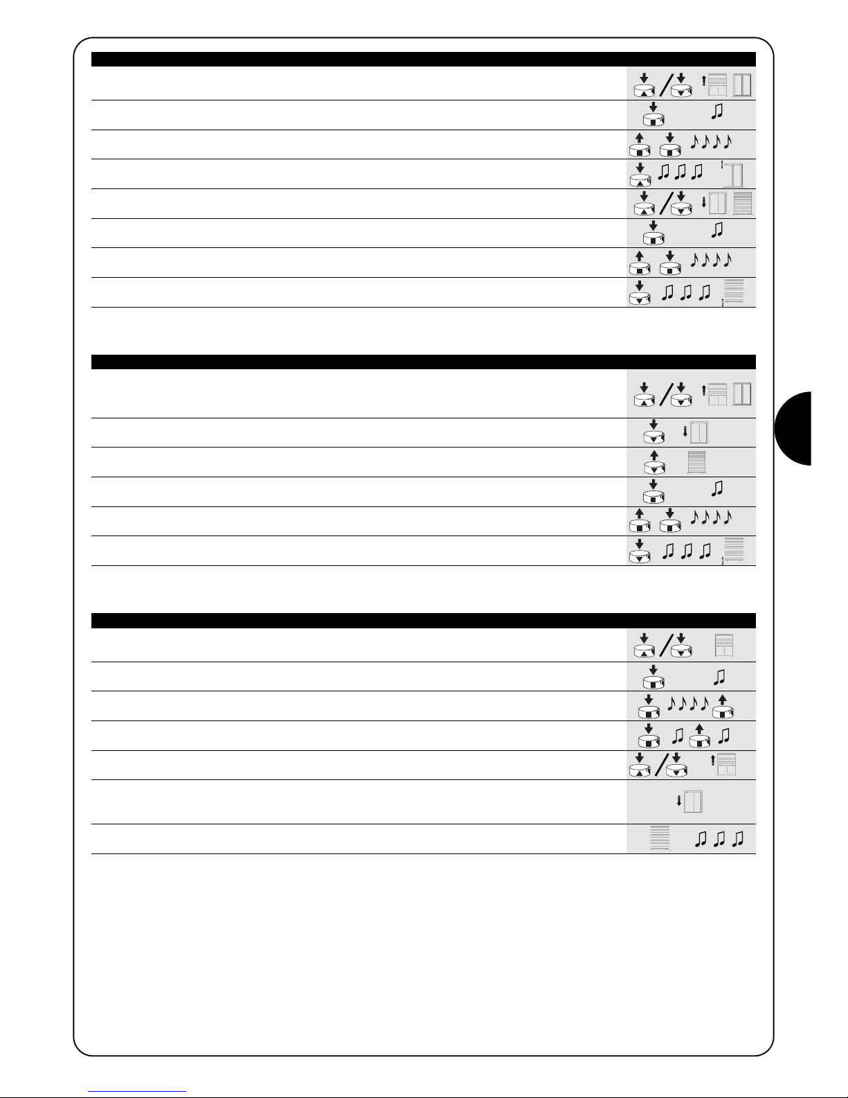
E
37
1. Mantenga apretado el botón ▲ o el botón ▼ de un transmisor memorizado hasta llegar a
la posición de apertura deseada
2. Mantenga apretado el botón ■ del transmisor hasta oír un tono de aviso
(transcurridos alrededor de 5 segundos). 5s
3. Suelte y oprima de nuevo durante otros 5 segundos el botón ■ hasta oír 4 tonos de aviso
rápidos. 5s
4. Presione el botón ▲ hasta que 3 tonos de aviso y un breve movimiento indiquen que la
posición de apertura ha sido memorizada.
5. Mantenga apretado el botón ▲ o el botón ▼ del telemando memorizado hasta llegar a la
posición de cierre deseada
6. Mantenga apretado el botón ■ del transmisor hasta oír un tono de aviso
(transcurridos alrededor de 5 segundos). 5s
7. Suelte y presione de nuevo durante otros 5 segundos el botón ■ hasta oír 4 tonos de aviso
rápidos. 5s
8. Presione el botón ▼ hasta que 3 tonos de aviso y un breve movimiento indiquen que la
posición de cierre “1” ha sido memorizada.
Nota: Ahora el botón ▲ accionará la maniobra de subida mientras que el botón ▼ accionará la de bajada.
La subida y la bajada se detendrán en correspondencia de las posiciones programadas.
Tabla "A3" Programación MANUAL de las Posiciones “0” y “1” (fig. 9) Ejemplo
1. Presione y mantenga apretado el botón ▲ o el botón ▼ de un telemando memorizado hasta
que la persiana se abra por completo y el motor se detenga en los topes de subida.
2. Presione y mantenga apretado el mando ▼ que hace bajar la persiana.
3. Suelte el botón ▼ cuando la persiana haya llegado a la posición deseada (“1”)
5s
4. Mantenga apretado el botón ■ del transmisor hasta oír un tono de aviso
(transcurridos alrededor de 5 segundos). 5s
5. Suelte y presione de nuevo durante otros 5 segundos el botón ■ hasta oír 4 tonos de aviso
rápidos. 5s
6. Presione el botón ▼ hasta que 3 tonos de aviso y un breve movimiento indiquen que la
posición de cierre “1” ha sido memorizada.
Nota: Ahora el botón ▲ accionará la maniobra de subida mientras que el botón ▼ accionará la de bajada.
La subida de la persiana se detendrán en correspondencia de los topes y la bajada en correspondencia de la posición programada.
Tabla "A4" Programación SEMIAUTOMÁTICA de las posiciones “0” y “1”(fig 10) Ejemplo
1. Compruebe que la persiana esté en mitad de carrera, de ser posible utilice los botones
▲ y ▼ del telemando memorizado para desplazar la persiana hasta mitad de su carrera.
2. Oprima y mantenga apretado el botón ■ de un transmisor memorizado hasta oír un tono
de aviso (transcurridos alrededor de 5 segundos) y suéltelo. 5s
3. Oprima nuevamente durante otros 5 segundos el botón ■ hasta oír 4 tonos de aviso
rápidos y suéltelo. 5s
4. Oprima nuevamente el botón ■ hasta oír el primero de los 2 tonos de aviso lentos.
5. La persiana deberá moverse hacia arriba, si el movimiento es hacia abajo hay que presionar
el botón ▲ y ▼ para hacer mover la persiana hacia arriba.
6. A este punto, el procedimiento proseguirá
automáticamente
:
primero se encontrará la posición “0” en correspondencia de los topes en la apertura y
después la posición “1” en correspondencia de los dispositivos de seguridad en el cierre.
7. El procedimiento se concluirá con la persiana completamente cerrada y con una señal
sonora de 3 tonos de aviso.
Nota: Ahora el botón ▲ accionará la maniobra de subida mientras que el botón ▼ accionará la de bajada.
La subida y la bajada se detendrán poco antes de los límites buscados.
Tabla "A5" Programación AUTOMÁTICA de las posiciones “0” y “1”(fig 11) Ejemplo

38
4.3) Programaciones opcionales
Las programaciones opcionales pueden hacerse sólo tras haber concluido con las programaciones de las posiciones “0” y “1”
Memorización de la posición intermedia “I”
Si se memoriza una posición intermedia “I” es posible mover la persiana hacia la posición programada presionando simultáneamente los 2
botones ▼ ▲ del transmisor.
Para memorizar la posición intermedia siga este procedimiento:
1. Utilizando los botones ▲■▼de un telemando coloque la persiana donde se quiere
memorizar la posición “I”.
2. Mantenga apretado el botón ■ hasta oír un tono de aviso (transcurridos alrededor de 5
segundos). 5s
3. Suelte y presione de nuevo durante otros 5 segundos el botón ■ hasta oír 4 tonos de aviso
rápidos. 5s
4. Presione juntos los botones ▼ y ▲ hasta que 3 tonos de aviso indiquen que la cota ha sido
memorizada.
Tabla "A6" Programación de la posición intermedia “I”(fig 12) Ejemplo
4.4) Modificación de las posiciones memorizadas
Para modificar las posiciones memorizadas, primero hay que borrarlas y después se pueden volver a programar las nuevas posiciones.
Si fuera necesario borrar todos los datos contenidos en la memoria de la central en los motores NEOMAT, se puede seguir este procedimiento. La memoria se puede borrar:
• con un transmisor no memorizado, empezando desde el punto A.
• con un transmisor memorizado, empezando el procedimiento desde el punto N° 1.
Se pueden borrar:
• sólo los códigos de los transmisores, terminando en el punto N° 4,
• todos los datos (códigos de los transmisores, posiciones, nivel del viento, dirección TTBUS, etc.) completando el procedimiento.
1. Mantenga apretado el botón ■ de un transmisor memorizado hasta oír un tono de aviso
(después de alrededor de 5 segundos) 5s
2. Suelte y presione de nuevo durante otros 5 segundos el botón ■ hasta oír 4 tonos de aviso
rápidos. 5s
3. Presione juntos los botones ▲ ▼ hasta que 5 tonos de aviso indiquen que la posición
intermedia ha sido cancelada.
Ahora es posible programar la nueva posición intermedia (Tabla “A6”)
Tabla "A7" Borrado de la posición intermedia “I” (fig 12) Ejemplo
1. Mantenga apretado el botón ■ de un transmisor memorizado hasta oír un tono de aviso
(después de alrededor de 5 segundos) 5s
2. Suelte y presione de nuevo durante otros 5 segundos el botón ■ hasta oír 4 tonos de aviso
rápidos. 5s
3. Oprima el botón ▲ (si se ha efectuado la programación automática o manual) o el botón ▼
(si se ha efectuado la programación semiautomática), hasta que 5 tonos de aviso señalen
que las posiciones “0” y “1” han sido borradas.
ATENCIÓN: tras haber cancelado la posiciones “0” y “1” la persiana se moverá en modo manual y habrá que memorizar las nuevas
posiciones (Tablas “A3”, “A4”, “A5”).
Tabla "A8" Borrado de las posiciones "0" y "1" (fig 13) Ejemplo
A. Con el motor no alimentado, active la entrada paso a paso (conecte el hilo blanco y negro)
y manténgala activa hasta el final del procedimiento.
B. Alimente el motor y espere los 2 tonos de aviso iniciales
1. Mantenga apretado el botón ■ de un transmisor memorizado hasta oír un tono de aviso
(después de alrededor de 5 segundos) 5s
2. Mantenga apretado el botón ▲ del transmisor hasta oír 3 tonos; suelte el botón ▲
exactamente durante el tercer tono de aviso. 5s
3. Mantenga apretado el botón ■ de un transmisor hasta que oiga 3 tonos; suelte el botón ■
exactamente durante el tercer tono de aviso.
4. Mantenga apretado el botón ▼ de un transmisor hasta que oiga 3 tonos; suelte el botón ▼
exactamente durante el tercer tono de aviso.
5. Si usted desea borrar todos los datos, presione juntos, antes de 2 segundos, los dos
botones ▲ y ▼ y después suéltelos. antes de 2s
Pasados algunos segundos, 5 tonos de aviso indican que todos los códigos de la memoria han sido borrados.
Tabla "A9" Borrado de la memoria (fig 14) Ejemplo
➨
➨
➨
PP
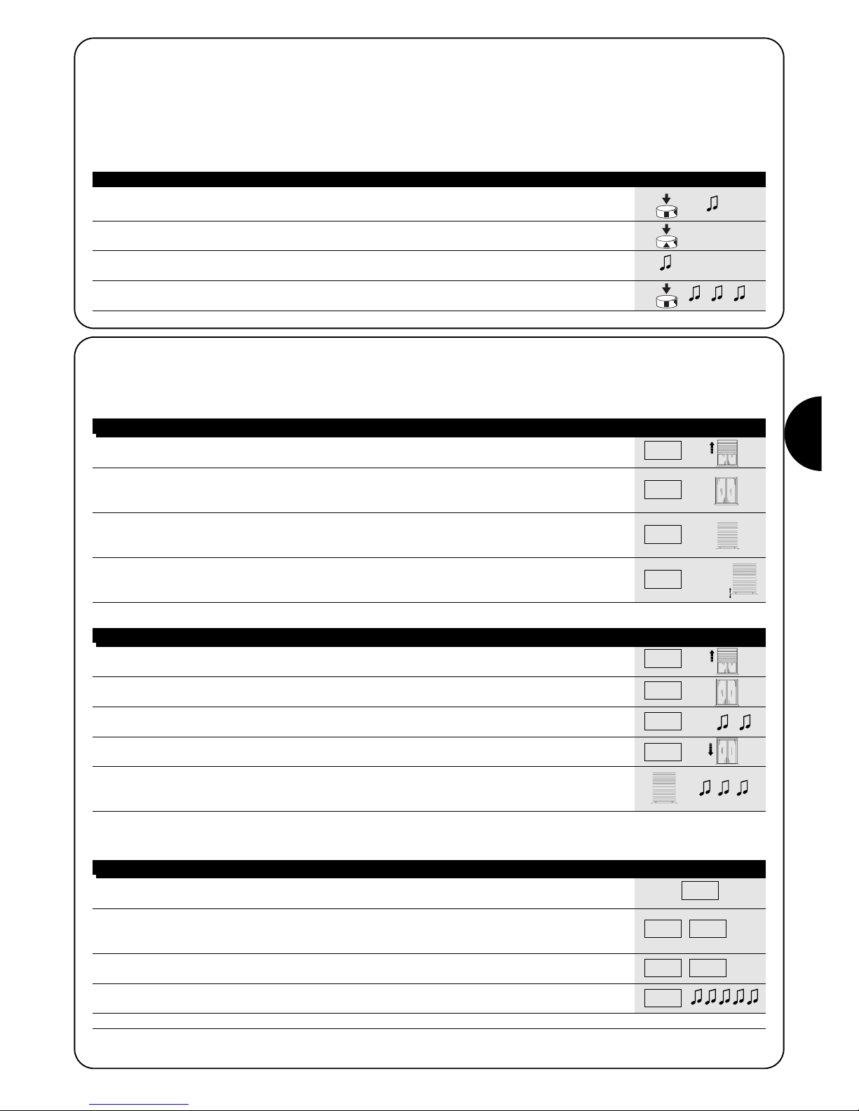
E
39
1. Presione el botón ■ de un transmisor memorizado hasta oír un tono de aviso
(después de alrededor de 5 segundos) 5s
2. Presione lentamente el botón ▲ la cantidad de veces (1, 2 ó 3) equivalente al nivel deseado
3. Después de un instante, se oirá una cantidad de tonos de aviso equivalente al nivel requerido.
4. Presione el botón ■ para confirmar, 3 tonos de aviso señalan la nueva programación. Espere 5
segundos como mínimo sin confirmar para abortar el procedimiento sin cambiar el nivel anterior.
Tabla“A10” Cambio del nivel de activación de la protección “viento” (fig 15) Ejemplo
4.5) Programación de los sensores climáticos
Si en la entrada "sensores" se conecta un sensor de viento, es posible seleccionar el nivel de activación entre 3 posibles niveles (1° = 15
km/h, 2° = 30 km/h y 3° = 45 km/h si se utiliza un sensor “VOLO”), de fábrica el nivel es el N° 2. Cuando el nivel es superado durante más
de 3 segundos, se activa un mando que equivale al botón ▲ y se bloquean todos los demás movimientos hasta que el viento no vuelve por
debajo del nivel programado durante un minuto como mínimo.
Para modificar el nivel programado:
X1= 15 km/h
X2= 30 km/h
X3= 45 km/h
X1= 15 km/h
X2= 30 km/h
X3= 45 km/h
1. Active el mando paso a paso; si la persiana se mueve hacia abajo suelte el mando y repita
la operación.
2. Mantenga activo el mando paso a paso hasta que el motor se detenga automáticamente
porque la persiana completamente abierta ha golpeado contra los topes (posición “0”).
Después suelte el mando
3. Al utilizar el mando de paso a paso (funcionamiento manual), detenga la persiana, durante el
movimiento de bajada, en correspondencia del punto de cierre deseado (posición “1”), a fin
de que el mando siguiente provoque la subida de la persiana.
4. Active 2 veces consecutivas (antes de 2 segundos) el mando paso a paso manteniendo activo
el segundo mando durante 5 segundos por lo menos (motor detenido), hasta que 3 tonos de
aviso y un breve movimiento de subida y bajada indiquen que la posición ha sido memorizada. X2(X5s)
Tabla "A11" Programación de las posiciones "0" y "1" con búsqueda SEMIAUTOMÁTICA Ejemplo
4.6) Programación de las posiciones sin transmisor
Si bien de una manera menos cómoda es posible programar los límites de carrera y las posiciones “0” y “1” sin telemando, utilizando solamente la entrada paso a paso.
En este caso pueden utilizarse sólo las programaciones SEMIAUTOMÁTICA y AUTOMÁTICA.
PP
PP
PP
PP
1. Active el mando paso a paso; si la persiana se mueve hacia abajo suelte el mando y repita
la operación.
2. Mantenga activo el mando paso a paso hasta que el motor se detenga automáticamente
porque la persiana completamente abierta ha golpeado los tapones (posición “0”).
3. Siga manteniendo activo el mando durante otros 5 segundos hasta que oiga 2 tonos de
aviso, suelte el mando. X5s
4. La persiana comienza a moverse en bajada para buscar la posición “1”. El procedimiento
puede interrumpirse nuevamente activando el mando paso a paso.
5. Cuando la persiana se cierra por completo en correspondencia de los dispositivos de
seguridad de enganche al eje, la persiana se detiene e indica con 3 tonos de aviso que
las posiciones “0” y “1” han sido programadas.
Nota: Con el mando paso a paso no es posible memorizar la cota de apertura parcial.
Tabla "A12" Programación de las posiciones "0" y "1" con búsqueda AUTOMÁTICA Ejemplo
PP
PP
PP
PP
Si usted quiere modificar la posiciones, tendrá que borrar todas las configuraciones efectuadas y repetir todo el procedimiento de nuevo
1. Active el mando paso a paso; si la persiana se mueve hacia arriba suelte el mando y
repita la operación. 3s
2. Mantenga activo el mando hasta que tras alrededor de 3 segundos comience una maniobra
de subida; active 2 veces consecutivas (antes de 2 segundos) el paso a paso manteniendo
activo el 2° mando, para detener y hacer reanudar la bajada de la persiana. 3s
3. Repita el punto anterior otras 3 veces.
Al 3° intento la maniobra de subida no arranca más. X3
4. Siga manteniendo activo el mando paso a paso durante otros 10 segundos hasta que los 5
tonos de aviso le indiquen que todas las posiciones han sido borradas.
Nota: Tras borrar las posiciones los movimientos se efectúan en modo manual.
Tabla "A13" Borrado de las posiciones "0" y "1" con el mando paso a paso Ejemplo
PP
PP PP
PPPPPP

40
Después de la alimentación, el motor no emite los 2 tonos
de aviso y la entrada Paso a Paso no acciona ningún movimiento.
Controle que el motor esté alimentado con la tensión de red prevista; si la alimentación es correcta, es probable que haya una avería
grave y entonces habrá que sustituir el motor.
Después de un mando por radio se oyen 6 tonos de aviso
y la maniobra no arranca. El radiomando está desincronizado;
hay que repetir la memorización del transmisor.
Después de un mando se oyen 10 tonos de aviso y después la maniobra arranca. El autodiagnóstico de los parámetros
en la memoria ha detectado alguna irregularidad (posición, dirección
TTBUS, nivel de viento y sol, dirección del movimiento incorrectos);
controle y, si fuera necesario, repita las programaciones.
Después de un mando el motor no se mueve.
• Podría haberse desconectado la protección térmica; en dicho
caso hay que esperar a que el motor se enfríe.
• Si hay memorizado un sensor de viento se podría haber supera-
do el umbral configurado.
•Si así no fuera, apague y encienda el motor, si no oye 2 tonos de
aviso es probable que se haya averiado gravemente y que tenga
que sustituirlo.
Durante la subida, antes de llegar a la posición prevista
(pos. “0”, pos. “I”), el motor se detiene y se oye que trata
de volver a arrancar por 3 veces.
Puede ser normal si se ha efectuado la programación de las posiciones “0” ”1” en modo SEMIAUTOMÁTICO: durante la subida,
cuando se detecta un esfuerzo excesivo, el motor se apaga durante 1 segundo y luego trata de concluir la maniobra; controle que no
haya obstáculos que impidan el movimiento.
Durante la bajada, antes de llegar a la posición prevista
(pos. “0”, pos. “I”), el motor se detiene.
Puede ser normal: cuando se detecta un esfuerzo excesivo, el motor
se apaga; controle que no haya obstáculos que impidan el movimiento.
El motor se mueve sólo en modo manual
Si las posiciones “0” y “1” no fueron programadas el movimiento de
subida y bajada del motor se realiza sólo en modo manual. Programe las posiciones “0” y “1”.
Las posiciones “0” y “1” están programadas, pero durante la bajada el movimiento se produce en modo manual.
El autodiagnóstico de los parámetros en la memoria ha detectado
un desperfecto en la posición del motor. Accione la subida de la persiana y espere a que alcance la posición “0”.
5) Qué hacer si… pequeña guía en caso de problemas!
6) Características técnicas
Motores tubulares serie
NEOMAT A
Tensión de alimentación y frecuencia : Véanse los datos técnicos en la etiqueta de cada modelo
Corriente y potencia : Véanse los datos técnicos en la etiqueta de cada modelo
Par y Velocidad : Véanse los datos técnicos en la etiqueta de cada modelo
Tiempo de funcionamiento continuo : Máximo 4 minutos
Ciclo de funcionamiento : Máximo 20%
Clase de protección : IP 44
Temperatura de funcionamiento : -10 ÷ 70 °C
Precisión (resolución) del fin de carrera electrónico : mayor que 0,55° (depende de la versión de NEOMAT)
Central electrónica
Tensión de las señales (paso a paso, sensores) : 24Vdc aprox.
Niveles sensor viento (anemómetro) : aprox. 30 o bien 15 ó 45 km/h (con anemómetro VOLO)
Longitud de los cables de las señales (paso a paso, sensores) : 30m máximo en las cercanías de otros cables, si no 100 m
Radiorreceptor
Frecuencia : 433.92 MHz
Codificación : 52 Bit rolling code FLOR
Alcance de los transmisores
ERGOy PLANO
: Estimada en 200 m al aire libre y en 35 m en el interior de edificios.
Nice S.p.a. se reserva el derecho de modificar los productos cuando lo considere necesario

E
41

42
Ostrzeżenia
Silniki z serii “NEOMAT A” służą do automatyzacji ruchu rolet i każde inne ich
zastosowanie jest nieprawidłowe i zabronione.
Silniki przeznaczone są do użytku w zespołach mieszkaniowych; czas pracy
ciągłej przewidziany jest na 4 minuty w cyklu 20%.
Przy wyborze typu silnika, w zależności od jego zastosowania, należy mieć
na uwadze moment nominalny i czas funkcjonowania wskazany na tabliczce
znamionowej. Minimalna średnica rury, gdzie może być zainstalowany silnik
NEOMAT SA, ma wynosić 40 mm, dla silnika NEOMAT MA - 52 mm i dla
silnika NEOMAT LA - 70 mm.
Instalowanie ma być wykonane przez techników według norm
bezpieczeństwa.
W urządzeniach montowanych na zewnątrz przewód zasilający z PCV
zainstalować wewnątrz kanalika zabezpieczającego. Chronić silnik przed
zgnieceniem, uderzeniem, spadnięciem lub kontaktem z płynami
jakiegokolwiek rodzaju; nie dziurawić i nie wkręcać śrub na całej długości rury
(rys. 1). W celu czynności konserwacyjnych lub napraw zwrócić się do
personelu technicznego.
Uwaga: niektóre fazy programowania mogą wykorzystać blokady
mechaniczne rolety (zaślepki lub sprężyny antywłamaniowe). W tym
wypadku należy wybrać silnik z najbardziej odpowiadającym momentem
mając na uwadze wagą rolety i unikając zbyt mocnych silników.
Silniki rurowe NEOMAT SA 35mm, NEOMAT MA 45mm (rys.2) i
NEOMAT LA 58mm posiadają centralę elektroniczną i wbudowany
odbiornik radiowy, który pracuje na częstotliwości 433.92 MHz z
technologią rolling code, gwarantując wysoki poziom bezpieczeństwa.
Do każdego silnika można wczytać do 14 pilotów z serii “ERGO”,
“PLANO” (rys. .3 i 4) lub “VOLO S RADIO”.
Wbudowana w silniku centrala posiada także system elektronicznych
wyłączników krańcowych dużej precyzji, który jest w stanie, w sposób
ciągły, odczytywać pozycję rolety.
W fazie programowania ustala się punkty graniczne rolety zamkniętej i
rolety otwartej (i ewentualne pozycje pośrednie); ruch rolety zatrzyma
się automatycznie po dojściu do tych dwóch pozycji.
Centrala odczytuje nawet gwałtowne zmiany i przesilenia silnika
przerywając natychmiast ruch; ta charakterystyka jest wykorzystana do
automatycznego programowania pozycji granicznych i wówczas gdy
roleta posiada zaślepki graniczne górne i sprężyny antywłamaniowe.
Programowanie granic ruchu i innych dodatkowych funkcji można
wykonać pilotem, sygnał akustyczny będzie kierował poszczególnymi
fazami. Silnikiem można sterować także przyciskiem zewnętrznym
(funkcją Krok po kroku) lub drogą Bus “TTBUS”.
Czujniki wiatru, słońca i deszczu, automatycznie uaktywniają system,
kiedy warunki klimatyczne tego wymagają.
1) Opis produktu
2) Instalacja
Przygotować silnik według następującej sekwencji (rys. 4):
1. Wsunąć tuleję (E) na silnik (A) do momentu założenia jej na
odpowiedni występ pierścienia (F).
2. Założyć adapter (D) na wał silnika. Mocowanie adaptera na silniku
NEOMAT SA jest automatyczne na zatrzask
3. Przymocować adapter na silniku NEOMAT MA pierścieniem
sprężystym na zatrzask
Rys. 4
A: Silnik rurowy NEOMAT A
B: Haczyk lub zawleczka do przymocowania
C: Wspornik i część dystansowa
D: Adapter napędowy
E: Tuleja
F: Pierścień
NEOMAT A jest produktem firmy Motus S.p.a. (TV) I. ERGO, PLANO, VOLO są produktem firmy Nice S.p.a.(TV) Włochy. Motus S.p.a. jest spółką należącą do grupy Nice S.p.a.Włochy
Wsunąć tak złożony silnik do rury wzniesienia rolety do momentu jej
nasunięcia na tuleję (E). Przykręcić rurę do adaptera (D) śrubą M4x10
tak, aby uniknąć możliwych przesunięć osiowych silnika (rys. 5). Na
koniec zablokować głowicę silnika we wsporniku (C), z ewentualną
częścią dystansową, haczykami lub zawleczkami (B).
2.1) Połączenia elektryczne
UWAGA: przy podłączeniu silnika należy zastosować
wyłącznik wielobiegunowy do odłączenia od sieci elektrycznej, gdzie odległość pomiędzy stykami ma wynosić co najmniej 3 mm (wyłącznik sekcyjny lub gniazdo i wtyczka, itp.)
UWAGA: skrupulatnie przestrzegać przewidzianych
połączeń; w wypadku niepewności nie próbować, ale zapoznać się z odpowiednimi szczegółowymi instrukcjami technicznymi, które dostępne są na stronie internetowej:
www.niceforyou.com.
Błędne wykonanie połączeń może spowodować uszkodzenia
i stworzyć niebezpieczne sytuacje.
Przewód do połączeń elektrycznych silnika NEOMAT A posiada 6 żył:
• Linia zasilania z sieci elektrycznej: Faza, Neutralna i Uziemienie
• Sygnały sterujące niskiego napięcia (SELV): Krok po Kroku lub Bus
“TTBUS” i czujniki klimatyczne
!
!
Brązowy = faza elektryczna
Niebieski = neutralny (zero)
Żółto/zielony = uziemienie
Czarny = Wspólny (0V)
Biały = Krok po kroku + “TTBUS”
Pomarańczowy = Czujniki klimatyczne
Etykietka
żółta
Etykietka
zielona
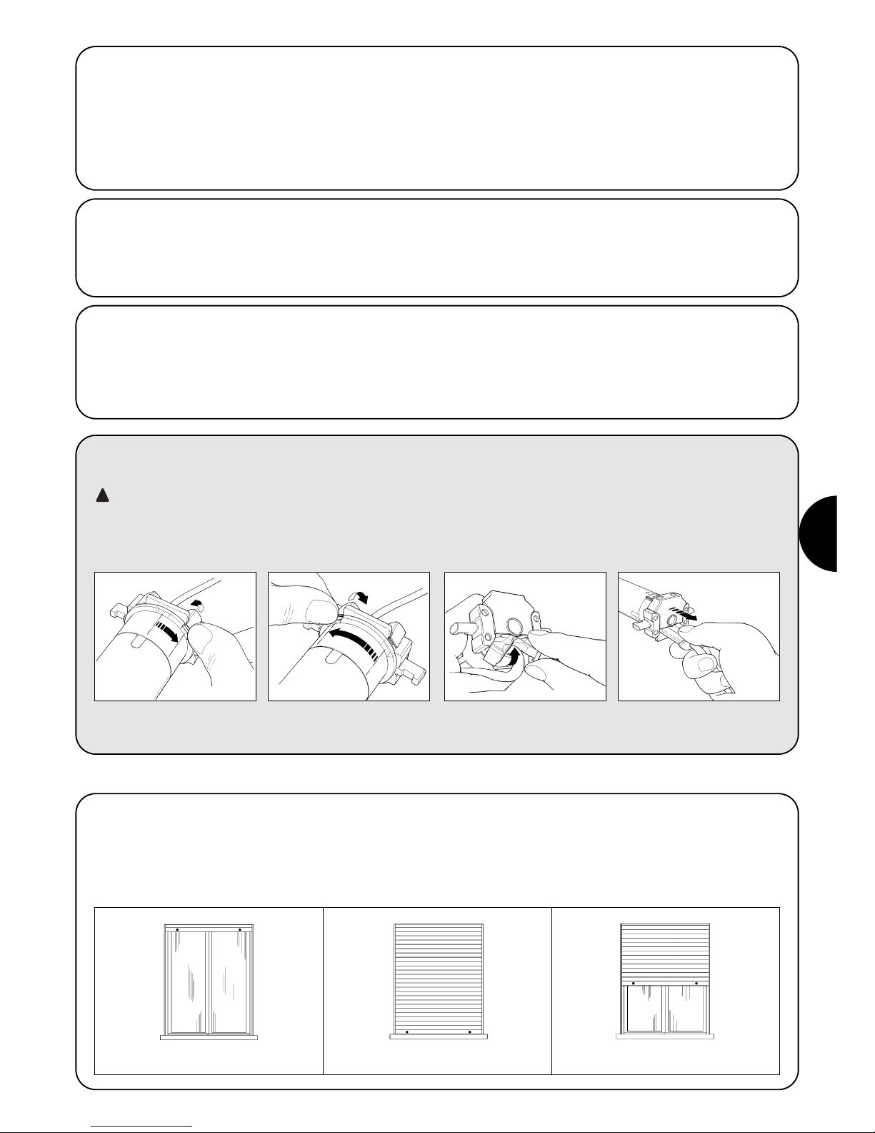
PL
43
2.2) Łącznik i przewód zasilający
(ten rozdział dotyczy tylko wersji NEOMAT A i jest przeznaczony dla techników serwisu obsługi)
UWAGA: gdy przewód zasilający jest uszkodzony należy go wymienić na identyczny dostępny u producenta lub w serwisie
technicznym.
Gdy zajdzie konieczność odłączenia silnika od przewodu zasilającego postąpić tak, jak wskazano na poniższych rysunkach:
!
Silniki rurowe z serii NEOMAT A posiadają elektroniczny wyłącznik
krańcowy, który przerywa ruch, kiedy roleta osiągnie pozycje graniczne
zamknięcia lub otwarcia.
Te dwie pozycje zapamiętane są w odpowiedniej fazie programowania, którą należy wykonać z silnikiem i z zasłoną już całkowicie zamontowaną.
Gdy pozycje “0” (roleta otwarta) i “1” (roleta zamknięta) nie zostały
jeszcze zapamiętane to sterowanie silnikiem jest również możliwe, sposobem ręcznym.
Można zaprogramować także pozycję pośrednią (Pos. “I”) częściowego otwarcia rolety.
Przekręcić tuleją do momentu
dopasowania nacięcia do jednego z
ząbków zaczepu, po czym odczepić.
Powtórzyć czynność dostosowania
dla następnego ząbka
Zgiąć przewód w kierunku do wnętrza
i ściągnąć zabezpieczenie odkręcając
delikatnie w kierunku na zewnątrz
Pociągnąć i wyciągnąć złącze
3) Regulacje
Roleta otwarta (pozycja 0) Roleta zamknięta (pozycja 1) Pozycja pośrednia (“I”)
2.1.2) Wejście “TTBUS”:
“TTBUS” jest to Bus rozszerzony do kontroli central sterujących silniki
rolet i zasłon. Bus przewiduje możliwość kontroli do 100 central, łącząc
je równolegle tylko 2 przewodami (wspólny i “TTBUS”).
Dodatkowe informacje umieszczone są w instrukcjach pilotów
“TTBUS”.
2.1.3) Czujniki klimatyczne:
Do wejścia “Czujników klimatycznych”, pomiędzy Wspólnym (żyła czarnea) i wejściem Czujników klimatycznych (żyła pomarańczowa) można
podłączyć prosty czujnik wiatru (anemometr) lub specjalny czujnik wiatr-słońce-deszcz.
Do tego samego czujnika można połączyć, równolegle 5 central,
uważając na prawidłową biegunowość sygnałów (we wszystkich silnikach przewód czarny ma być połączony do przewodu czarnego i
przewód pomarańczowy do przewodu pomarańczowego).
2.1.1) Wejście “Krok po Kroku”
Do ręcznego sterowania automatyki można podłączyć prosty przycisk
(pomiędzy Wspólnym i wejściem Krok po kroku). Funkcjonowanie
odbywa się według sekwencji: wznisienie-stop-obniżenie-stop.
Gdy przycisk będzie pod naciskiem ponad 3 sekundy (ale krócej niż 10
sekund) uaktywnia się ruch wzniesienia (odpowiadający przyciskowi ▲
na pilocie). Gdy przycisk będzie pod naciskiem ponad 10 sekund
uaktywnia się ruch obniżania (odwijania) (odpowiadający przyciskowi
▼). Ta specjalna funkcja może być używana do “synchronizacji” kilku
silników do tego samego ruchu niezależnie od pozycji, w których się
znajdują

44
Programowanie podzielone jest na trzy fazy:
1. Wczytywanie pilotów
2. Programowanie pozycji “0” i “1”
3. Programowanie opcjonalne
UWAGA: Wszystkie sekwencje zapisywania nadajników i
programowanie parametrów są określone czasowo, to
znaczy, że należy je wykonać w ograniczonym czasie.
• Zapisywanie pilotów, gdzie przewidywane są “grupy”
należy wykonać po uprzednim wyborze grupy, do której
dostosuje się silnik.
• Programowanie drogą radiową można wykonać we
wszystkich silnikach, które znajdują się w zasięgu
nadajnika; zasilenie wówczas należy podłączyć tylko do
tego, który będzie programowany.
4) Programowanie
4.1) Zapisywanie pilotów
Każdy pilot zostanie rozpoznawany przez wbudowany do centrali NEOMAT A odbiornik; rozpozna on indywidualny “kod” nadajnika. Każdy nadajnik
ma własny kod. Niezbędna jest więc faza “zapisywania”, poprzez którą dostosowuje się centralę do rozpoznania każdego pojedynczego pilota.
Gdy w pamięci odbiornika nie ma zapisanego żadnego kodu to zapis pierwszego pilota wykonuje się następująco:
!
1. Zaraz po zasileni centrali usłyszymy 2 długie sygnały (biiip)
2. W ciągu do 5 sekund przycisnąć i utrzymać pod naciskiem przycisk ■ wczytywanego nadajnika
(na około 3 sekundy) 3s
3. Zwolnić przycisk ■ kiedy usłyszymy pierwszy z 3 sygnałów, które potwierdzą zapisanie
Nota: Gdy w centrali już są zapisane kody to zaraz po jej włączeniu usłyszymy 2 krótkie sygnały (bip) i nie będzie możliwe wykonanie
czynności wyżej opisanych ale należy postąpić następująco (Tabela “A2”)
Tabela “A1” Zapisywanie pierwszego pilota (rys 7) Przykład
1. Utrzymać pod naciskiem (przez około 5 s) przycisk ■ nowego nadajnika aż do usłyszenia sygnału)
nowego 5s
2. Powoli 3 krotnie przycisnąć przycisk ■ nadajnika już wpisanego (starego)
starego X3
3. Przycisnąć jeszcze raz przycisk ■ nowego nadajnika.
nowego
4. Na zakończenie 3 sygnały potwierdzą prawidłowe zapisanie nowego nadajnika.
Uwaga: Gdy pamięć jest zapełniona (14 kodów), 6 sygnałów będzie oznaczało, że nadajnik nie będzie zapisany.
Tabela “A2” Zapisywanie innych pilotów (rys 8) Przykład
Gdy jeden lub więcej nadajników zostały już zapisane to następne zapisujemy w poniższy sposób:
4.2) Programowanie pozycji “0” i “1”
W automatyce rolet mogą zaistnieć 3 przypadki i związane są one z obecnością lub nie elementów „blokujących” bieg rolety: „zaślepki” (korki)
jako punkty graniczne biegu podnoszenia rolety (ograniczają nawijanie rolety) i – lub „sprężyny antywłamaniowe” (nie pozwalają na podniesienie
rolety gdy jest ona całkowicie obniżona).
W zależności od istniejących lub nie tych ograniczników (zaślepki i-lub sprężyny) programowanie może odbyć się inaczej:
Ręczne programowanie wyłączników krańcowych (Nie są konieczne zaślepki lub sprężyny antywłamaniowe)
Półautomatyczne programowanie wyłączników krańcowych (Konieczne są zaślepki przy nawijaniu)
Automatyczne programowanie wyłączników krańcowych (Konieczne są zaślepki i sprężyny antywłamaniowe w odwijaniu)
Przy programowaniu pozycji należy zastosować już zapisany pilot. Dopóki nie zostaną zaprogramowane pozycje “0” i “1” to ruch ma odbyć się
ręcznie. Na początku kierunek obrotu silnika nie jest określony, kierunek silnika jest automatycznie dostosowywany do przycisku pilota.

PL
45
1. Przycisnąć i utrzymać pod naciskiem przycisk ▲ lub ▼ nadajnika już wpisanego aż do
ustawienia się na żądanej pozycji wzniesienia.
2. Przycisnąć i utrzymać pod naciskiem przycisk ■ nadajnika aż do usłyszenia sygnału
(po około 5 sekund) 5s
3. Zwolnić i ponownie przycisnąć na następne 5 sekund przycisk ■ aż do usłyszenia 4
szybkich sygnałów 5s
4. Przycisnąć przycisk ▲ aż do momentu, kiedy 3 sygnały i krótki ruch zasygnalizuje, że wartość
wzniesienia została zapisana
5. Przycisnąć i utrzymać pod naciskiem przycisk ▲ lub ▼nadajnika już wpisanego aż do
ustawienia się na żądanej pozycji wzniesienia.
6. Przycisnąć i utrzymać pod naciskiem przycisk ■ nadajnika aż do usłyszenia sygnału
(po około 5 sekund) 5s
7. Zwolnić i ponownie przycisnąć na następne 5 sekund przycisk ■ aż do usłyszenia 4 szybkich
sygnałów 5s
8. Przycisnąć przycisk ▼ aż do momentu, kiedy 3 sygnały potwierdzą, że pozycja obni ania
jest już zapisana.
Uwaga: Teraz przycisk ▲ zarządzi ruch wzniesienia a przycisk ▼ obniżenia.
Ruch wzniesienia i obniżenia zatrzyma się w zaprogramowanej pozycji.
Tabela “A3” R CZNE programowanie pozycji “0” i “1” (rys 9) Przykład
1. Przycisnąć i utrzymać pod naciskiem przycisk ▲ lub ▼ nadajnika już wpisanego aż do
całkowitego nawinięcia się rolety i kiedy silnik zatrzyma się na zaślepkach w fazie wzniesienia.
2. Przycisnąć i utrzymać pod naciskiem przycisk ▼, który spuszcza roletę.
3. Zwolnić przycisk ▼ kiedy roleta osiągnie żądaną pozycję (“1”)
5s
4. Przycisnąć i utrzymać pod naciskiem przycisk ■ nadajnika już wpisanego aż do usłyszenia
sygnału (po około 5 sekundach) 5s
5. Zwolnić i ponownie przycisnąć na następne 5 sekund przycisk ■ aż do usłyszenia 4 szybkich
sygnałów 5s
6. Przycisnąć przycisk ▼ aż do momentu, kiedy 3 sygnały potwierdzą, że pozycja wzniesienia jest
już zapisana.
Uwaga: przycisk ▲ kierował będzie ruchem wzniesienia a przycisk ▼ obniżania.
Przy nawijaniu roleta zatrzyma się odpowiednio do zaślepek, przy obniżaniu odpowiednio w pozycji zaprogramowanej.
Tabela “A4” PÓŁAUTOMATYCZNE programowanie pozycji “0” i “1”(rys.10) Przykład
1. Sprawdzić czy roleta znajduje się w połowie biegu, ewentualnie przyciskami ▲ i ▼ już wpisanego
pilota ustawić roletę na połowie biegu.
2. Nacisnąć i utrzymać pod naciskiem przycisk ■ już zapisanego nadajnika aż do usłyszenia
sygnału bip (po około 5 sekundach), po czym zwolnić. 5s
3. Ponownie nacisnąć przycisk na następne ■ aż do usłyszenia 4 szybkich sygnałów, po
czym zwolnić. 5s
4. Ponownie nacisnąć przycisk ■ aż do usłyszenia pierwszego z 2 wolnych sygnałów.
5. Roleta powinna poruszać się w kierunku do góry; gdy ruch odbywa się w kierunku do dołu
należy przycisnąć przycisk ▲ lub ▼ w celu poruszenia rolety w kierunku do góry.
6. Procedura w tym miejscu będzie kontynuowała automatycznie:
najpierw znaleziona zostanie pozycja “0” przy zaślepkach przy odwijaniu i następnie pozycja “1”
odpowiednio do sprężyn anty włamaniowych w nawijaniu.
7. Procedura zakończy się z całkowicie zamkniętą roletą (odwiniętą) i 3 sygnałami.
Uwaga: Teraz przycisk ▲ kieruje ruchem wzniesienia a przycisk ▼ kierunkiem obniżania .
Ruch wzniesienia i obniżani a zatrzymają się w wyszukanych punktach.
Tabela “A5” AUTOMATYCZNE programowanie pozycji “0” i “1” (rys 11) Przykład

46
4.3) Programowanie opcjonalne
Opcjonalne programowanie jest możliwe tylko po zakończeniu programowania pozycji “0” i “1”
Zapisywanie pozycji pośredniej “I”.
Gdy zapisana została pozycja pośrednia “I” będzie można ustawić roletę w zaprogramowanej pozycji jednoczesnym przyciśnięciem dwóch
przycisków nadajnika:
Zapamiętywanie pośredniej pozycji wykonać według poniższej procedury:
1. Przyciskami ▲■▼ pilota ustawić roletę na pozycji, którą zachowamy jako pozycję pośrednią “I”.
2. Przycisnąć i utrzymać pod naciskiem przycisk ■ aż do usłyszenia sygnału (po około 5 sekundach)
5s
3. Zwolnić i ponownie przycisnąć na następne 5 sekund przycisk ■ aż do usłyszenia 4 szybkich
sygnałów 5s
4. Przycisnąć jednocześnie przyciski ▼ ▲ aż do momentu, kiedy 3 sygnały potwierdzą, że
wartość została zapisanaa
Tabela “A6” Programowanie pośredniej pozycji “I” (fig 12) Przykład
4.4) Zmiana zapisanych pozycji
Aby zmienić zapisane pozycje należy je najpierw skasować i zaprogramować ponownie.
Gdy zajdzie konieczność skasowania wszystkich danych w pamięci centrali NEOMAT można wykonać poniższą procedurę.
Kasowanie pamięci jest możliwe:
• pilotem nie zapisanym począwszy od punktu A.
• jednym już zapisanym począwszy procedurę od punktu N 1
Można skasować:
• Tylko kody pilotów, kończąc na punkcie N 4
• Wszystkie dane (kody pilotów, pozycje, poziomy wiatru i słońca, adresu TTBUS, itp.) kończąc procedurę.
1. Przycisnąć i utrzymać pod naciskiem przycisk ■ nadajnika już wpisanego aż do usłyszenia
sygnału (po około 5 sekundach) 5s
2. Zwolnić i ponownie przycisnąć na następne 5 sekund przycisk ■ aż do usłyszenia 4 szybkich
sygnałów 5s
3. Przycisnąć jednocześnie przyciski aż do momentu kiedy 5 sygnałów ▲ ▼ zasygnalizują ,
że pozycja pośrednia została już skasowana.
Teraz będzie możliwe zaprogramowanie nowej pośredniej pozycji (Tabela “A6”)
Tabela “A7” Kasowanie pozycji pośredniej “I” (rys. 12) Przykład
1. Przycisnąć i utrzymać pod naciskiem przycisk ■ nadajnika już wpisanego aż do usłyszenia
sygnału (po około 5 sekundach) 5s
2. Zwolnić i ponownie przycisnąć na następne 5 sekund przycisk ■ aż do usłyszenia 4 szybkich
sygnałów 5s
3. Nacisnąć przycisk ▲ (w wypadku zaprogramowania automatycznego lub ręcznego) lub przycisk
▼ (w wypadku zaprogramowania półautomatycznego), aż do momentu kiedy 5 sygnałów
poinformują o tym, że pozycje “0” i “1” zostały skasowane.
UWAGA: Po wykasowaniu pozycji “0” i “1” zasłona może być poruszana tylko ręcznie; konieczne jest więc zapisanie nowej pozycji.
(Tabele “A3”, “A4”, “A5”)
Tabela “A8” Kasowanie pozycji “0”i “1” (rys. 13) Przykład
A. Podczas gdy silnik nie jest zasilany uaktywniamy wejście Krok po kroku, wejście to ma być
aktywne do momentu zakończenia procedury (podłączyć przewód biały i czarny)
B. Podłączyć zasilanie do silnika i odczekać na 2 początkowe sygnały
1. Przycisnąć i utrzymać pod naciskiem przycisk ■ nadajnika już wpisanego aż do usłyszenia
sygnału (po około 5 sekundach) 5s
2. Przycisnąć i utrzymać pod naciskiem przycisk ▲nadajnika aż do usłyszenia 3 sygnałów;
zwolnić przycisk ▲ dokładnie w momencie trwania trzeciego sygnału 5s
3. Przycisnąć i utrzymać pod naciskiem przycisk ■ nadajnika aż do usłyszenia 3 bip; zwolnić
przycisk ■ dokładnie w momencie trwania trzeciego sygnału
4. Przycisnąć i utrzymać pod naciskiem przycisk ▼ nadajnika aż do usłyszenia 3 sygnałów;
zwolnić przycisk ▼ dokładnie w momencie trwania trzeciego sygnału
5. Gdy chcemy skasować wszystkie dane to w ciągu 2 sekund przycisnąć jednocześnie ▲ e ▼,
później zwolnić je. do 2s
Po kilku sekundach 5 sygnałów potwierdzi, że wszystkie kody w pamięci zostały wykasowane.
Tabela “A9” Kasowanie pamięci (rys. 14) Przykład
➨
➨
➨
PP

PL
47
1. Przycisnąć przycisk ■ nadajnika już wpisanego aż do usłyszenia sygnału (po około 5 sekundach)
5s
2. Przycisnąć wolno przycisk ▲ tyle razy, ile wynosi żądany numer poziomu czułości (1, 2 lub 3)
3. Po krótkiej chwili usłyszymy tyle sygnałów, jaki jest numer wybranego poziomu
4. Przycisnąć przycisk ■ aby potwierdzić, 3 sygnały potwierdzą nowe ustawienie. Aby wyjść z
procedury bez zmiany poprzedniego poziomu należy odczekać 5 sekund bez potwierdzenia
Tabela “10” Zmiana poziomu interwencji zabezpieczenia "wiatr" (rys 15) Przykład
4.5) Programowanie czujników klimatycznych
Gdy na wejście „czujników” zostanie podłączony czujnik wiatru możliwe będzie wykonanie wyboru jednego z 3 możliwych poziomów czułości (1
= 15Km/godz., 2 = 30Km,/godz. i 3 = 45 Km/godz., gdy będzie zastosowany czujnik “VOLO”); Fabrycznie ustawienie to poziom nr.2.
Kiedy poziom zostanie przekroczony na ponad 3 sekundy, uaktywnia się włącza się funkcja przypisana do przycisku ▲ i ruch zostanie
zablokowany aż do momentu, kiedy prędkość wiatru nie spadnie poniżej poziomu zaprogramowanego na co najmniej jedną minutę.
Jak zmieniać zaprogramowany poziom:
X1= 15 km/h
X2= 30 km/h
X3= 45 km/h
X1= 15 km/h
X2= 30 km/h
X3= 45 km/h
1. Przycisnąć przycisk Krok po roku; gdy roleta porusza się w dół (odwija się) to zwolnić przycisk
i powtórzyć czynność.
2. Przytrzymać przycisk Krok po kroku do momentu, kiedy silnik zatrzyma się automatycznie,
ponieważ całkowicie odwięnieta roleta uderzy w zaslepki (pozycja “0”).
Po czym zwolnić przycisk
3. Przyciskiem Krok po kroku (funkcja ręczna) zatrzymać roletę w fazie odwijania w miejscu, który
będzie punktem maksymalnej pozycji (pozycja “1”) tak, aby następną fazą już była faza
wzniesienia.
4. Dwukrotnie przycisnąć (w ciągu do 2 sekund) przycisk Krok o kroku i przytrzymać po drugim
naciśnięciu przez co najmniej 5 sekund (silnik zatrzymany); sygnały i krótki ruch wzniesienia i
obniżenia zasygnalizują, że pozycja została zapisana X2(X5s)
Tabela “11” Programowanie POZYCJI “0” i “1” poszukiwanie PÓŁAUTOMATYCZNYM Przykład
4.6) Programowani pozycji bez pilota
Choć nie jest to łatwe, można również wykonać programowanie pozycji zatrzymania i pozycji “0” i “1” bez pilota poprzez zastosowanie funkcji
Krok po kroku.
W tym wypadku możliwe jest programowanie PÓŁAUTOMATYCZNE I AUTOMATYCZNE.
PP
PP
PP
PP
1. Przycisnąć przycisk Krok po kroku; gdy roleta obniża się należy zwolnić przycisk i powtórzyć
czynność.
2. Przytrzymać przycisk Krok po kroku do momentu, kiedy silnik zatrzyma się automatycznie,
ponieważ roleta będzie już całkowicie nawinięta (pozycja “0”).
3. Przytrzymać przycisk przez następne 5 sekund aż do momentu, kiedy roleta zacznie krótki ruch
obniżania (odwijania). X5s
4. Roleta zaczyna poruszać się w kierunku do dołu w poszukiwaniu pozycji “1”.
Procedura może być przerwana uaktywniając ponownie przycisk Krok po kroku.
5. Kiedy roleta całkowicie się zamknie odpowiednio do sprężyn antywłamaniowych to zatrzyma
się i 3 sygnały sygnalizują zaprogramowanie pozycji “0” i “1”.
Uwaga: Funkcją Krok po kroku nie jest możliwe zapisanie pozycji częściowego otwarcia.
Tabela “12” Programowanie pozycji “0” i “1” z poszukiwaniem AUTOMATYCZNYM Przykład
PP
PP
PP
PP
Gdy mamy zamiar zmienić pozycje należy wykasować wszystkie ustawienia i ponownie powtórzyć procedurę
1. Przycisnąć przycisk Krok po kroku; gdy roleta wznosi się należy zwolnić przycisk i powtórzyć
czynność. 3s
2. Przytrzymać przycisk aż do momentu, kiedy po około 3 sekundach zacznie się ruch wzniesienia;
przycisnąć 2 krotnie (w ciągu 2 sekund) przycisk Krok po kroku i przytrzymać po 2 przyciśnięciu,
aby zatrzymać i włączyć obniżanie rolety. 3s
3. Powtórzyć poprzednią fazę 3 krotnie.
Po trzeciej próbie nie odbędzie się ruch wzniesienia. X3
4. Utrzymać pod naciskiem przycisk Krok po kroku przez następne 10 sekund aż do momentu,
kiedy 5 sygnałów potwierdzą, że wszystkie pozycje zostały wykasowane
Uwaga: Po skasowaniu pozycji ruch może być wykonany ręcznie
Tabela “13” Kasowanie pozycji “0” i “1” przyciskiem krok po kroku Przykład
PP
PP PP
PPPPPP

48
Po podłączeniu zasilania silnik nie wydaje 2 sygnałów i
wejście Krok po kroku nie steruje żadnym ruchem.
Sprawdzić czy silnik podłączony został do sieci z odpowiednim
napięciem, gdy zasilenie jest właściwe to jest możliwe, że silnik jest
wadliwy i powinien być wymieniony.
Po wydaniu polecenia drogą radiową słyszymy 6 sygnałów,
ale ruch nie odbywa się.
Pilot nie został zsynchronizowany, należy powtórzyć zapisywanie
nadajnika.
Po wydaniu polecenia słyszymy 10 sygnałów i później ruch
startuje.
Autodiagnoza parametrów w pamięci odczytała jakąś anomalię (błędna
pozycja, adres TTBUS, poziom wiatru i słońca, kierunek ruchu).
Sprawdzić i ewentualnie powtórzyć programowanie.
Po wydaniu komendy silnik nie rusza się.
• Być może zainterweniowało zabezpieczenie termiczne, w tym
wypadku wystarczy odczekać do momentu ochłodzenia się silnika
• Gdy podłączony jest czujnik wiatru to może został przekroczony
próg czułości.
• Można też wyłączyć i włączyć silnik, gdy nie usłyszymy 2 sygnałów
to możliwe, że jest to poważny powód i silnik powinien być
wymieniony.
W trakcie wzniesienia i przed osiągnięciem ustawionej
pozycji (poz. “0” , poz. “C” poz. “I”), silnik zatrzymuje się i
słyszymy, że 3 krotnie wykonuje próbę startu.
To objaw normalny po zaprogramowaniu pozycji “0” i “1” w sposobie
PÓŁAUTOMATYCZNYM: gdy w trakcie wzniesienia odczytane
zostanie przeciążenie to silnik włączony zostanie na 1 sekundę, po
której ponownie wykonuje próbę startu. Sprawdzić i wyeliminować
ewentualne przeszkody.
Przy obniżaniu przed osiągnięciem zaprogramowanej pozycji
(poz. “0”, “1”, poz. “I”), silnik zatrzymuje się.
To objaw normalny: gdy w trakcie obniżania odczytane zostanie
przeciążenie to silnik zostanie wyłączony; Sprawdzić i wyeliminować
ewentualne przeszkody.
Silnik porusza się tylko “w ruchu ręcznym”.
Gdy pozycje “0” i “1” nie zostały zaprogramowane to ruch silnika
wzniesienia i obniżenia odbędzie się tylko ręcznie. Zaprogramować
pozycję “0” i “1”.
Pozycje “0” i “1” są zaprogramowane, ale obniżanie odbywa
się ręcznie.
Autodiagnoza parametrów w pamięci odczytała anomalię w pozycji
silnika. Polecić wzniesienie rolety i odczekać do momentu osiągnięcia
pozycji “0”.
5) Co zrobić, kiedy... czyli mały poradnik w momencie, kiedy coś jest nie tak!
6) Dane techniczne
Silniki rurowe z serii NEOMAT A
Napięcie zasilania i częstotliwość : Patrz dane techniczne na etykietce każdego typu
Prąd i moc : Patrz dane techniczne na etykietce każdego typu
Moment i prędkość : tapparellaPatrz dane techniczne na etykietce każdego typu
Czas ciągłej pracy : Maksymalnie 4 minuty
Cykl pracy : Maksymalnie 20%
Stopień zabezpieczenia : IP 44
Temperatura funkcjonowania : -10 ÷ 70 °C
Dokładność (rozdzielczość) elektronicznego wyłącznika krańcowego : Wyższa niż 0.55° (Zależy od typu NEOMAT)
Centrala elektroniczna
Napięcie sygnałów (krok po kroku, czujniki) : Około 24Vps (prąd stały)
Poziom czujnika wiatru (anemometr) : Około 30 lub 15 lub 45 km/godz. (przy anemometrze VOLO)
Długość przewodów, sygnałów (krok po kroku, czujniki) : do 100m, w pobliżu innych przewodów do 30m
Odbiornik radiowy
Częstotliwość : 433.92 MHz
Kodowanie Bit rolling code (kod dynamicznie zmienny) FLOR : 52 Bit rolling code FLOR
Zasięg nadajników ERGO i PLANO : określony na 200 m w wolnej przestrzeni i 35 m wewnątrz budynków
Firma Nice S.p.a. rezerwuje sobie prawo do wprowadzenia zmiany w produktach w każdym momencie gdy będzie uważała to za konieczne

PL
49
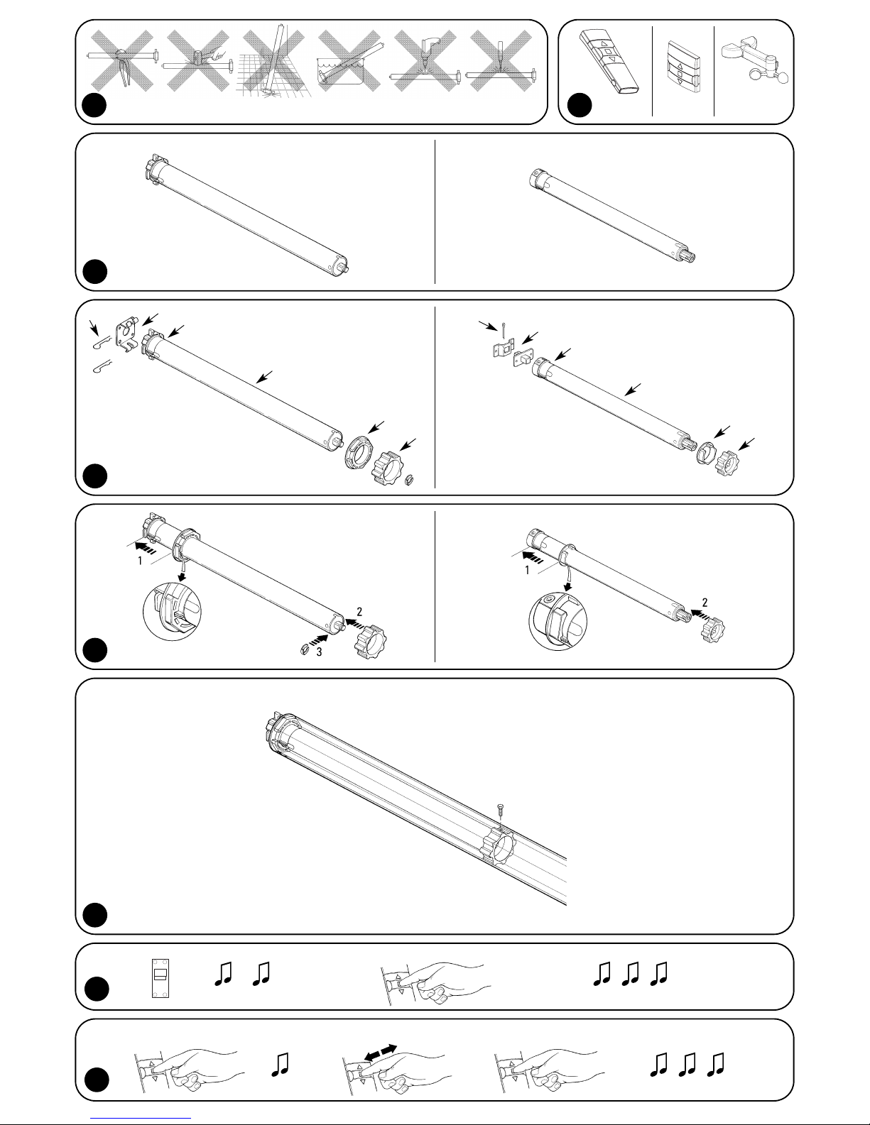
ERGO PLANO
VOLO S
RADIO
2
3
NEOMAT MA NEOMAT SA
4
5
6
A
B
C
D
E
F
D
E
A
F
C
B
1
7
ON
8
~3 s
+5 s X3 X1
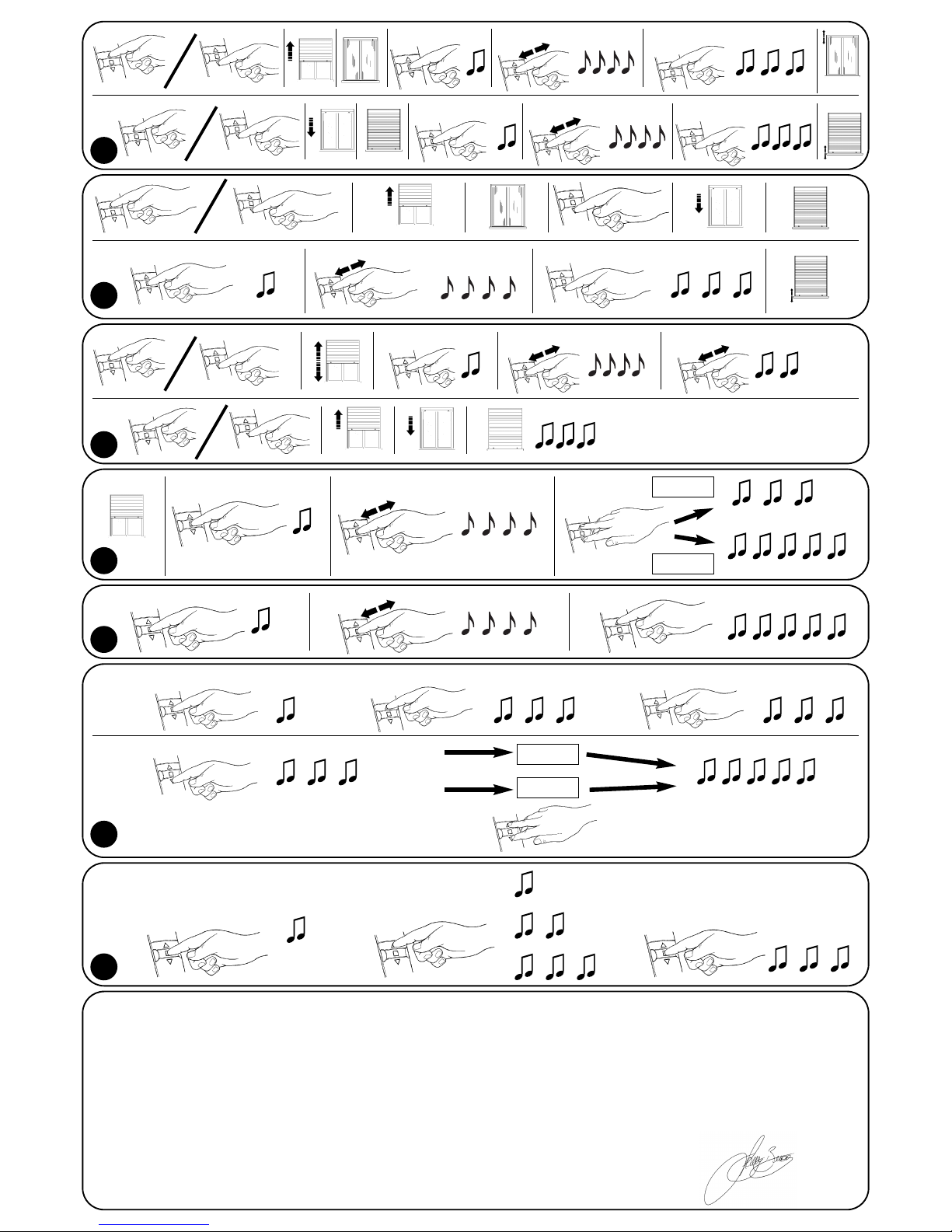
GB
I
F
D
E
Dichiarazione di conformità N°: Axis Nemo A Rev 0
declaration of conformity
NEOMAT A è prodotto da MOTUS S.p.a. (TV) ed è identico al corrispettivo modello “Axis Nemo A”. Motus S.p.a. è una società del gruppo Nice S.p.a.
NEOMAT A is produced by Motus S.p.a. (TV) I and is identical of the corresponding model “Axis Nemo A”. Motus S.p.a. is a company of the Nice S.p.a. group
MOTUS S.p.a. via Pezza Alta 13, 31046 Z.I. Rustignè - ODERZO - ITALY
dichiara che il prodotto: “Axis Nemo A” / declares that the product: “Axis Nemo A”
Motoriduttore per automatizzare tapparelle / Gearmotor for shutter automation
È conforme ai Requisiti Essenziali di Sicurezza delle Direttive: / Complies with the Essential Safety Requirements of Directives:
73/23/CEE Direttiva Bassa Tensione (LVD) / Low Voltage Directive (LVD)
89/336/CEE Direttiva Compatibilità Elettromagnetica (EMC) / Electromagnetic Compatibility (EMC)
1999/5/CE Apparecchiature radio e terminali di telecomunicazione (Allegato II) / Radio equipment and telecommunications terminal(Annex II)
Amministratore Delegato / General Manager
Data /date Lauro Buoro
14 Luglio 2003
9
15
14
2 s
Only TX
3° bip
3° bip 3° bip+5 s
+5 s
+5 s
X1= 15 Km/h
X2= 30 Km/h
X3= 45 Km/h
-2 s X 1
All
+5 s
+5 s
10
+5 s +5 s
12
+5 s +5 s
program
erase
13
+5 s +5 s
+5 s
11
+5 s +5 s +5 s

89.028/NS REV. 01
www.niceforyou.com
Nice S.p.a. Oderzo TV Italia
Via Pezza Alta, 13 Z.I. Rustignè
Tel. +39.0422.85.38.38
Fax +39.0422.85.35.85
info@niceforyou.com
Nice Padova Sarmeola I
Tel. +39.049.89.78.93.2
Fax +39.049.89.73.85.2
info.pd@niceforyou.com
Nice Roma I
Tel. +39.06.72.67.17.61
Fax +39.06.72.67.55.20
info.roma@niceforyou.com
Nice Belgium
Leuven (Heverlee) B
Tel. +32.(0)16.38.69.00
Fax +32.(0)16.38.69.01
info@nicebelgium.be
Nice España Madrid E
Tel. +34.9.16.16.33.00
Fax +34.9.16.16.30.10
kamarautom@nexo.es
Nice France Buchelay F
Tel. +33.(0)1.30.33.95.95
Fax +33.(0)1.30.33.95.96
info@nicefrance.fr
Nice France Sud Aubagne F
Tel. +33.(0)4.42.62.42.52
Fax +33.(0)4.42.62.42.50
info.marseille@nicefrance.fr
Nice Rhône-Alpes
Decines Charpieu F
Tel. +33.(0)4.78.26.56.53
Fax +33.(0)4.78.26.57.53
info.lyon@nicefrance.fr
Nice Polska Pruszków PL
Tel. +48.22.728.33.22
Fax +48.22.728.25.10
nice@nice.com.pl
 Loading...