


Nice
MC424L
Control unit
EN - Instructions and warnings for installation and use

ENGLISH
Translation of the original instructions in full
CONTENTS
1 GENERAL SAFETY WARNINGS AND PRECAUTIONS . . . . . 2
2 PRODUCT DESCRIPTION AND INTENDED USE. . . . . . . . . . 3
2.1 List of control unit parts . . . . . . . . . . . . . . . . . . . . . . . . . . . . 3
3 INSTALLATION. . . . . . . . . . . . . . . . . . . . . . . . . . . . . . . . . . . . . 4
3.1 Pre-installation checks . . . . . . . . . . . . . . . . . . . . . . . . . . . . . 4
3.2 Product usage limits . . . . . . . . . . . . . . . . . . . . . . . . . . . . . . 4
3.3 Product identification and overall dimensions . . . . . . . . . . . 4
3.4 Typical installation . . . . . . . . . . . . . . . . . . . . . . . . . . . . . . . . 4
3.5 Installing the control unit . . . . . . . . . . . . . . . . . . . . . . . . . . . 5
4 ELECTRICAL CONNECTIONS . . . . . . . . . . . . . . . . . . . . . . . . 5
4.1 Preliminary checks . . . . . . . . . . . . . . . . . . . . . . . . . . . . . . . . 5
4.2 Wiring diagram and description of connections . . . . . . . . . 6
4.2.1 Wiring diagram . . . . . . . . . . . . . . . . . . . . . . . . . . . . . . . . 6
4.2.2 Description of connections . . . . . . . . . . . . . . . . . . . . . . . 7
4.2.3 Operations for connection . . . . . . . . . . . . . . . . . . . . . . . 7
4.2.4 Notes on connections . . . . . . . . . . . . . . . . . . . . . . . . . . . 8
4.2.5 ALT (STOP) input type . . . . . . . . . . . . . . . . . . . . . . . . . . 8
4.3 Initial start-up and electrical connections test . . . . . . . . . . . 9
4.4 Motor selector . . . . . . . . . . . . . . . . . . . . . . . . . . . . . . . . . . 10
4.5 Automatic limit switch search and “STOP” input
acquisition . . . . . . . . . . . . . . . . . . . . . . . . . . . . . . . . . . . . . 10
5 TESTING AND COMMISSIONING . . . . . . . . . . . . . . . . . . . . . 11
5.1 Testing . . . . . . . . . . . . . . . . . . . . . . . . . . . . . . . . . . . . . . . . 11
5.2 Commissioning . . . . . . . . . . . . . . . . . . . . . . . . . . . . . . . . . 11
6 PROGRAMMING . . . . . . . . . . . . . . . . . . . . . . . . . . . . . . . . . . 11
6.1 Using the programming buttons . . . . . . . . . . . . . . . . . . . . 11
6.2 Pre-set functions . . . . . . . . . . . . . . . . . . . . . . . . . . . . . . . . 12
6.3 Level 1 programming (ON-OFF) . . . . . . . . . . . . . . . . . . . . 12
6.3.1 Level 1 programming procedure . . . . . . . . . . . . . . . . . 12
6.4 Level 2 programming (adjustable parameters) . . . . . . . . . 13
6.4.1 Level 2 programming procedure . . . . . . . . . . . . . . . . . 13
6.5 Memory deletion . . . . . . . . . . . . . . . . . . . . . . . . . . . . . . . . 15
6.6 Memorising the transmitters . . . . . . . . . . . . . . . . . . . . . . . 15
6.6.1 Procedure for memorising transmitter buttons . . . . . . . 15
6.6.2 Number of transmitters that can be memorised . . . . . . 15
6.6.3 Transmitter memorisation and deletion procedures . . . 15
6.7 LOCKING AND UNLOCKING THE MEMORY . . . . . . . . . . 17
7 TROUBLESHOOTING... (troubleshooting guide) . . . . . . . . 17
7.1 Signalling through warning light . . . . . . . . . . . . . . . . . . . . 17
7.2 Signals on the control unit . . . . . . . . . . . . . . . . . . . . . . . . . 18
7.3 Maintenance notification . . . . . . . . . . . . . . . . . . . . . . . . . . 19
7.4 Anomaly log . . . . . . . . . . . . . . . . . . . . . . . . . . . . . . . . . . . . 19
8 FURTHER INFORMATION (Accessories). . . . . . . . . . . . . . . 20
8.1 Connecting an SM-type radio receiver . . . . . . . . . . . . . . . 20
8.2 Connecting the IBT4N interface . . . . . . . . . . . . . . . . . . . . 20
8.3 Connecting the PS124 back-up battery . . . . . . . . . . . . . . 20
8.4 Connecting the Solemyo system . . . . . . . . . . . . . . . . . . . . 21
9 PRODUCT MAINTENANCE . . . . . . . . . . . . . . . . . . . . . . . . . . 21
10 PRODUCT DISPOSAL . . . . . . . . . . . . . . . . . . . . . . . . . . . . . . 21
11 TECHNICAL SPECIFICATIONS. . . . . . . . . . . . . . . . . . . . . . . 22
12 CONFORMITY . . . . . . . . . . . . . . . . . . . . . . . . . . . . . . . . . . . . 22
INSTRUCTIONS AND WARNINGS FOR THE USER . . . . . . 23
1
1 GENERAL SAFETY WARNINGS AND PRECAUTIONS
a
a
a
PRECAUTIONS
Prior to installing the appliance, carefully read and
observe these instructions, since incorrect installation can cause serious harm to people and damage
to the appliance. Store them with care.
According to the latest European legislation, an
automated device must be constructed in conform-
ity to the harmonised rules specied in the current
Machinery Directive, which allow for declaring the
presumed conformity of the automation. Consequently, all the operations for connecting the product to the mains electricity, its commissioning and
maintenance must be carried out exclusively by a
qualied and expert technician.
In order to avoid any danger from inadvertent resetting of the thermal cut-off device, this appliance
must not be powered through an external switching
device, such as a timer, or connected to a supply
that is regularly powered or switched off by the circuit.
WARNING! Please abide by the following warnings:
– Before commencing the installation, check the “Prod-
uct technical specications”, in particular whether this
product is suitable for automating your guided part.
Should it not be suitable, do NOT proceed with the installation.
– The product cannot be used before it has been com-
missioned as specied in the “Testing and commissioning” chapter.
– Before proceeding with the product’s installation,
check that all the materials are in good working order
and suited to the intended applications.
– The product is not intended for use by persons (includ-
ing children) with reduced physical, sensory or mental
capacities, nor by anyone lacking sufcient experience
or familiarity with the product.
– Children must not play with the appliance.
– Do not allow children to play with the product’s control
devices. Keep the remote controls out of reach of chil-
dren.
– The system’s power supply network must include a dis-
connection device (not supplied) with a contact open-
ing gap permitting complete disconnection under the
conditions envisaged by Overvoltage Category III.
– During the installation process, handle the product with
care by avoiding crushing, impacts, falls or contact
with liquids of any kind. Do not place the product near
sources of heat nor expose it to open ames. All these
actions can damage the product and cause it to mal-
function, or lead to dangerous situations. Should this
occur, immediately suspend the installation process
and contact the Technical Assistance Service.
– The manufacturer declines all liability for damages to
property, objects or people resulting from failure to
observe the assembly instructions. In such cases, the
warranty for material defects shall not apply.
– The weighted sound pressure level of the emission A is
lower than 70 dB(A).
– Cleaning and maintenance reserved for the user must
not be carried out by unsupervised children.
– Before working on the system (maintenance, cleaning),
always disconnect the product from the mains power
supply.
GENERAL SAFETY WARNINGS AND
2 – ENGLISH

– Inspect the system frequently, in particular the cables,
springs and supports to detect any imbalances and
signs of wear or damage. Do not use the product if it
needs to be repaired or adjusted, because defective
installation or incorrect balancing of the automation can
lead to injuries.
– The packing materials of the product must be disposed
of in compliance with local regulations.
2
2 PRODUCT DESCRIPTION AND INTENDED USE
MC424L is an electronic control unit for the automation of swing gates MC424L can command 24 V WINGO, TOO, SFAB elec-
tro-mechanical actuators. it incorporates an amperometric device that veries the force of the motors connected to it. This system
allows for automatically detecting the limit switches, memorising the work times of each motor and detecting any obstacles during
normal gate movement. These characteristics simplify the installation considerably, as the leaf offsets and work times do not require
any adjusting.
The control unit is programmed in advance for the most frequently used functions and incorporates a radio receiver for the remote
controls. In addition, a straightforward procedure can be implemented to select more specic functions (see the “PROGRAMMING” chapter).
MC424L is equipped with an SM-type connector for slot-in radio receivers (see the “Connecting an SM-type radio receiver“
paragraph) and an IBT4N-type connector which, through the IBT4N interface, can be used to connect BusT4 devices, such as the
Oview programmer (see the “Connecting the IBT4N interface” paragraph).
The control unit is congured for being powered with PS124 back-up batteries which, in case of a power outage, function as an
emergency power supply (see the “Connecting the PS124 back-up battery” paragraph). Moreover, the MC424L is congured for
being connected to a Solemyo solar power kit (see the “Connecting the Solemyo system” paragraph).
a
PRODUCT DESCRIPTION AND INTENDED USE
Any use of the product other than the intended use described is not allowed!
2.1 LIST OF CONTROL UNIT PARTS
The control unit is made up of an electronic command and control board housed and protected inside the box. “Figure 1” shows
the main parts making up the board.
1
L10
E F G H I M N
M M 5 6 7 8 9 10 11 12 131 2 3 4
M M
OK
L9
L11
L12
L13
R
S
L
U
N
D
T
C
B
A
A 24 V~ power supply connector
B Connector for PS124 back-up battery / Solemyo solar
power kit
C Service fuse (2 A, type F)
D “SM” connector for radio receiver
E M1 motor terminal (starts rst during the closing
phase)
F M2 motor terminal (starts rst during the opening
phase)
G Warning light terminal
H OGI output or electric lock terminal
I 24 VDC terminals for services and phototest
L9..L13 Input LEDs
OK “LED OK” status LED
L1
L8
..
P1
P2
P3
P4
LR
O
Q
L1..L8 Programming LED
LR Radio programming LED
M Input terminals
N Terminals for radio antenna
O Motor selector
Q Connector for IBT4N
R Mains fuse
S Mains power supply (L-Live; N-Neutral)
T Earth connection
U Cable clamp
P1..P3 Control unit programming buttons
P4 Radio programming button
ENGLISH – 3

3
310 mm
122 mm
3 INSTALLATION
INSTALLATION
3.4 TYPICAL INSTALLATION
“Figure 3” shows an example of an automation system constructed using Nice components.
3.1 PRE-INSTALLATION CHECKS
Before proceeding with the product’s installation, it is necessary
to:
– check the integrity of the supply
– check that all the materials are in good working order and
suited to the intended use
– check that all operating conditions comply with that specied
in the “Product usage limits” paragraph and in the “TECHNI-
CAL SPECIFICATIONS” chapter
– check that the chosen installation location is compatible with
the product’s overall dimensions (see “Figure 2”)
– check that the surface chosen for installing the product is sol-
id and can ensure stable attachment
– make sure that the installation area is not subject to ooding; if
necessary, the product must be installed appropriately raised
above ground level
– check that the space around the product allows safe and easy
access
– check that all electrical cables to be used belong to the type
listed in “Table 1”
– check that the automation has mechanical stops in both the
opening and closing phases.
3.2 PRODUCT USAGE LIMITS
The product must be used exclusively with WG2024, WG3524,
WG4024, WG5024, TOO3024, TOO4524, XME2024 gearmotors
and in accordance with the corresponding usage limits.
3.3 PRODUCT IDENTIFICATION AND OVERALL DIMENSIONS
The overall dimensions and label (A) that allow for identifying the
product are shown in “Figure 2”.
2
3
G
A WINGO, TOO, SFAB 24 V electro-mechanical actuator
B WINGO, TOO, SFAB 24 V electro-mechanical actuator
C Warning light
D Key selector
E “PHOTO” pair of photocells
F “PHOTO1” pair of photocells
G “PHOTO2” pair of photocells
H Control unit
These above-mentioned components are positioned according
to a typical standard layout.
In particular, bear in mind that:
– for the characteristics and connection of the photocells, con-
sult the specic instructions of the product
– the intervention of the “PHOTO” pair of photocells during the
opening phase has no effect, while it triggers a reversal during
the closing phase
– the intervention of the “PHOTO1” pair of photocells stops the
manoeuvre during both the opening and closing phases
– the intervention of the “PHOTO2” pair of photocells during the
closing phase (connected to the suitably congured AUX input) has no effect, while it triggers a reversal during the opening phase.
l
C
H
G
F F
Bear in mind that motor M1 is the rst to start for
the closing movement, while motor M2 is the rst to
start for the opening movement (“Figure 4”).
E E
A
B
D
232 mm
4
A
M1 M2
Before proceeding with the installation, prepare the
a
electrical cables required for the system by referring to the “Wiring diagram and description of con-
nections” paragraph and to that specied in the “
TECHNICAL SPECIFICATIONS” chapter.
The cables used must be suited to the type of envi-
a
ronment of the installation site.
When laying the ducting for routing the electrical
a
cables and for the cable entry point into the control
unit housing, check that there are no water deposits in the junction wells nor condensate in the connection ducts, as water and damp conditions could
damage the product’s electronic circuits.
4 – ENGLISH

3.5 INSTALLING THE CONTROL UNIT
Secure the control unit to an unmovable, vertical,
a
at surface adequately protected against possible
impacts. The lower part of the control unit must be
at least 40 cm above the ground.
The control unit is also suitable for being installed
l
outdoors, as it is supplied in a container that, if adequately installed, guarantees an IP54 protection
rating.
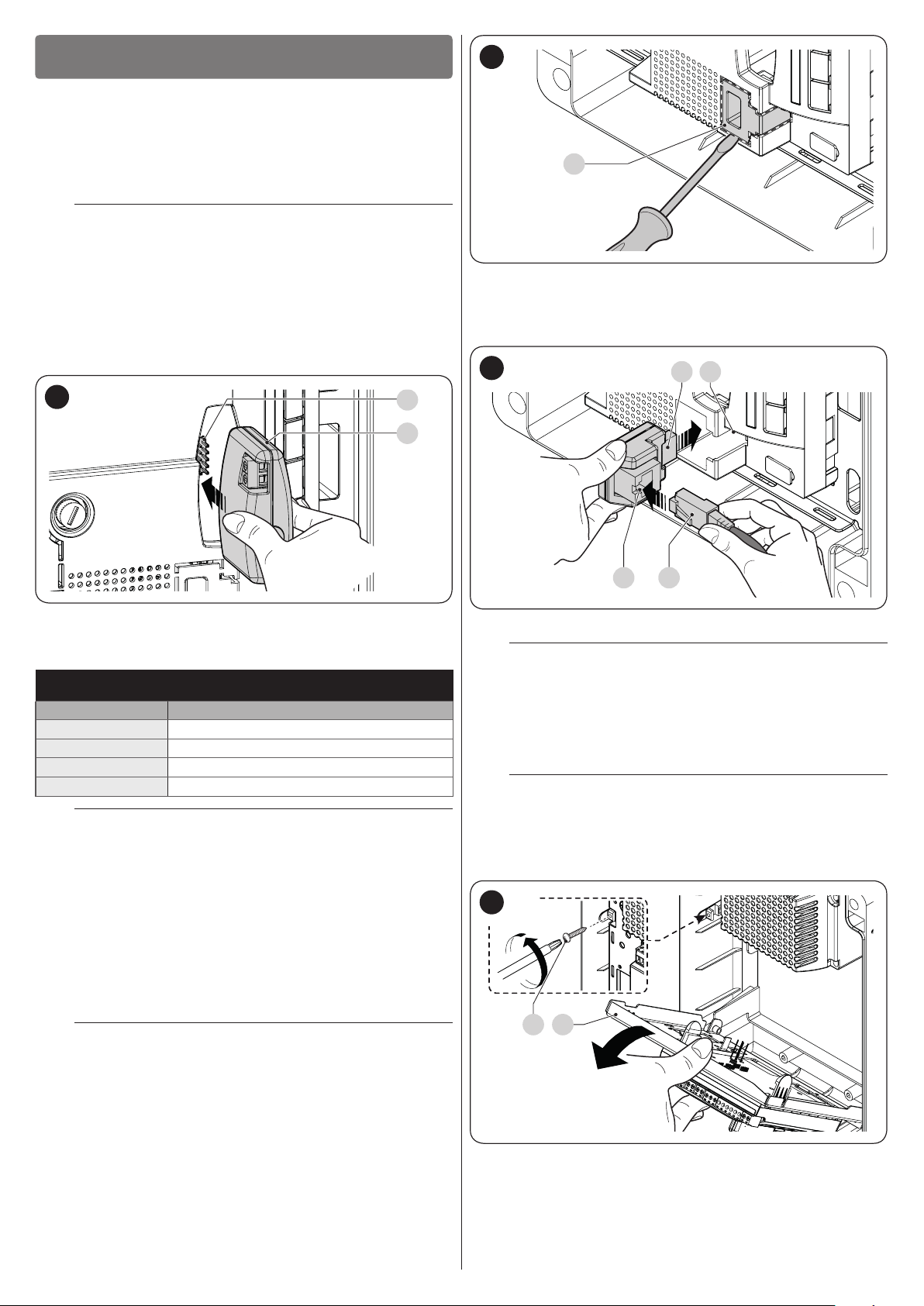
To secure the control unit (“Figure 5” and “Figure 6”):
1. loosen the screws (A) and remove the cover (B) of the
control unit
2. identify the pre-cut holes (C) located along the lower side
of the box and perforate the ones used to pass the electrical cables
The side cable entry (D) can only be used if the con-
l
trol unit is installed indoors, in a protected environment.
5
B
A
6
205 mm
G
F
237 mm
E
D
C
3. drill the wall (E) by observing the measurements shown in
the gure and arrange suitable wall plugs (not supplied)
4. position the box (F) and fasten it with the screws (G) (not
supplied)
5. arrange cable glands for passing the connecting cables
6. make the electrical connections by operating as de-
scribed in the “ELECTRICAL CONNECTIONS” chapter.
To install any other devices used on the automated
l
system, refer to the respective instruction manuals.
7. after making the electrical connections, put the cover (B)
back on and tighten the screws (A).
4
4 ELECTRICAL CONNECTIONS
ELECTRICAL CONNECTIONS
4.1 PRELIMINARY CHECKS
All electrical connections must be made with the
f
system disconnected from the mains electricity and
with the back-up battery (if present) disconnected.
The connection operations must only be carried out
a
by qualied personnel.
Check that all electrical cables to be used are of the
f
suitable type
ENGLISH – 5

4.2 WIRING DIAGRAM AND DESCRIPTION OF CONNECTIONS
4.2.1 Wiring diagram
7
Connection with “Stand-by all” active
A
(energy saving)
TX RX
OGI
M M 5 6 7 8 9 10 11 12 131 2 3 4M M
5 - 10 RX = PHOTO
5 - 11 RX = PHOTO1
5 - 13 RX = PHOTO2
PHOTO2
Standard connection: without using the
B
“Stand-by all” and without the “Phototest”
TX RX
OGI
M M 5 6 7 8 9 10 11 12 131 2 3 4M M
8-10 RX = PHOTO
8-11 RX = PHOTO1
8-13 RX = PHOTO2 (AUX)
Connection without the “Stand-by all”
C
and with the “Phototest”
TX RX
OGI
M M 5 6 7 8 9 10 11 12 131 2 3 4M M
8-10 RX = PHOTO
8-11 RX = PHOTO1
8-13 RX = PHOTO2 (AUX)
Connection without the “Stand-by all”, with the
D
“Phototest” and without the “Photo1”
TX RX
OGI
M M 5 6 7 8 9 10 11 12 131 2 3 4M M
8-10 RX = PHOTO
6 – ENGLISH

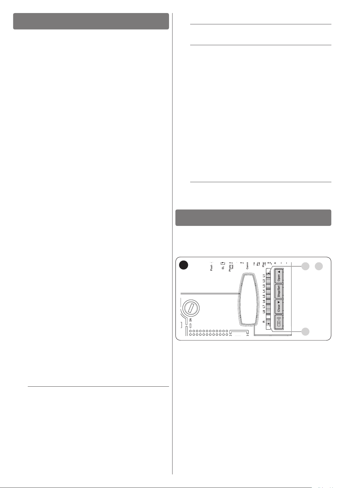
4.2.2 Description of connections
L
N
T
A
C
B
The meaning of the codes/wording stamped on the electronic board near the relative terminals is described below.
ELECTRICAL CONNECTIONS
Terminals Function Description Cable type
120/230/250 V ~ 50/60
Hz POWER SUPPLY
Motor 1
Mains power supply 3 x 1.5 mm
Connection of motor M1 [note 1]
3 x 1.5 mm
Motor 2 Connection of motor M2 3 x 1.5 mm
1÷2
3÷4
5
Warning light
OGI / Electric lock
24 V c common
input (with Stand-by
all / phototest)
Connection of the 24 V c max 25 W warning light
Connection of the 24 V c max 5 W Open Gate Indicator or 12 V c max 15
VA Electric Lock (see the “PROGRAMMING” chapter)
+24 V c power supply for TX photocells with phototest (max 100 mA);
“COMMON” for all safety inputs, with “Stand-by all” function active [note 2]
6 0 V c 0 V power supply c for services
7 24 V c Services power supply, without “Stand-by all” (24 V c max 200 mA)
8 Common 24 V c Common for all inputs (+24 V c) without “Stand-by all”
9
10
11
12
13
ALT (STOP)
Input with STOP function (emergency, safety lock) [note 3]
FOTO (PHOTO) NC input for safety devices (photocells, sensitive edges) 1 x 0.5 mm
FOTO1 (PHOTO1) NC input for safety devices (photocells, sensitive edges) 1 x 0.5 mm
PASSO-PASSO
(STEP-BY-STEP)
AUX
Input for cyclic operation (OPEN-STOP-CLOSE-STOP) 1 x 0.5 mm
Auxiliary input [note 4]
Antenna Radio receiver antenna connection
2 x 1 mm
OGI: 2 x 0.5 mm
Electric lock: 2 x 1
2
mm
1 x 0.5 mm
1 x 0.5 mm
1 x 0.5 mm
1 x 0.5 mm
1 x 0.5 mm
1 x 0.5 mm
RG58-type shielded
cable
Table 1
2
2
2
2
2
2
2
2
2
2
2
2
2
2
Note 1 Not used for single-leaf gates (the control unit automatically recognises whether there is only one motor installed).
Note 2 The “Stand-by all” is used to limit consumption; for further details on the electrical connections, refer to the “Stand-by all /
Phototest connection” paragraph, and consult the “PROGRAMMING” chapter for information on programming.
Note 3 The ALT (STOP) input can be used for NC contacts or 8.2 kΩ xed resistor contacts in self-recognition mode (see the “
PROGRAMMING” chapter).
Note 4 The AUX auxiliary input is programmed by default with the “Type 1 partial open” function, but can be programmed with one
of the functions shown in “Table 2”.
Table 2
PROGRAMMABLE FUNCTIONS FOR THE AUX INPUT
Function Type of input Description
TYPE 1 PARTIAL OPEN
TYPE 2 PARTIAL OPEN
OPEN
CLOSE
PHOTO 2
STOP
EXCLUDED
NO (normally open) Opens the upper leaf completely
NO (normally open) Opens the two leaves halfway
NO (normally open) Performs the open manoeuvre only
NO (normally open) Performs the close manoeuvre only
NC (normally closed) PHOTO 2 function
NO (normally open) Stops the manoeuvre
-- No function
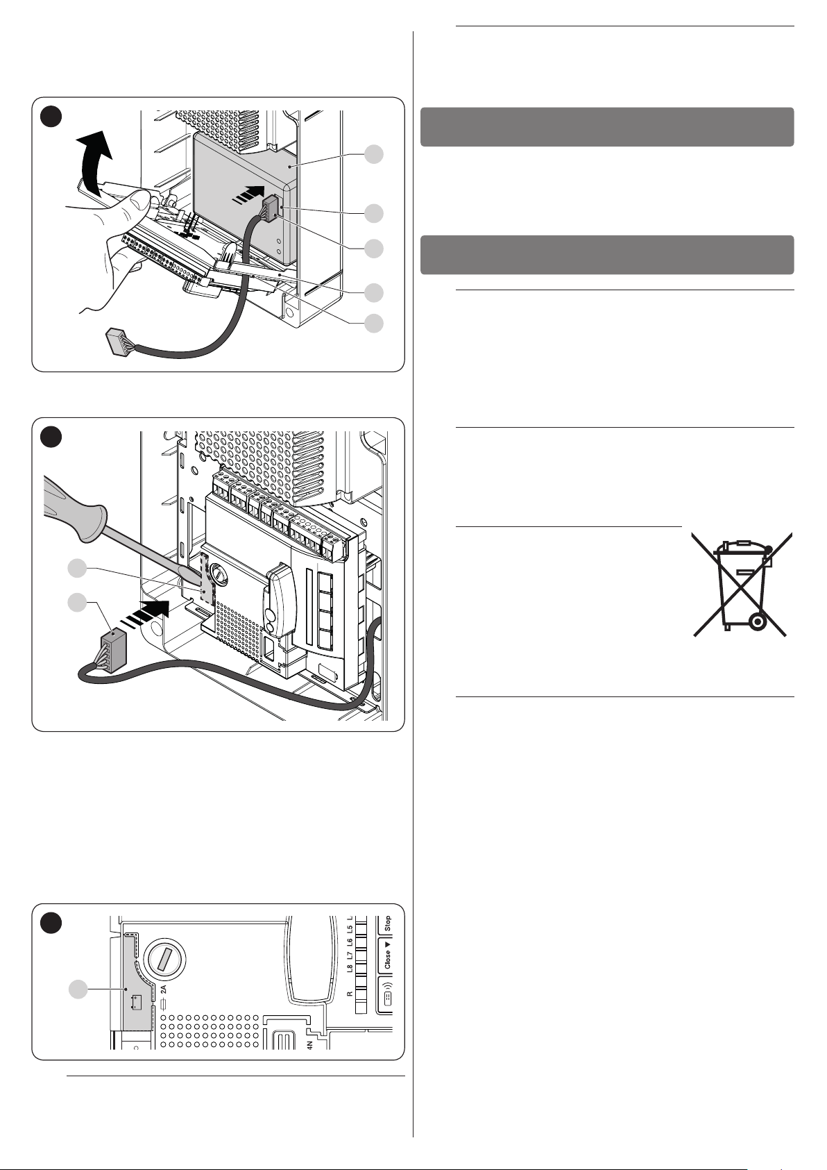
4.2.3 Operations for connection
To make the electrical connections (“Figure 7”):
8
1. remove the terminals from their housings
2. connect the various devices to the relevant terminals ac-
cording to the diagram shown in “Figure 7”
3. put the terminals back into their housings.
4. connect the power supply cable to points (A) and (B) and
secure it with the cable clamp (C) (“Figure 8”).
ENGLISH – 7

4.2.4 Notes on connections
STEP BY STEP
12 8 8 13
AUX
NC NCNO NOC C
Most of the connections are extremely easy to make, as they are
largely connections directed at a single user or contact. Below
are some examples on how to connect external devices.
Connection of the selector to carry out the “STEP-BY-STEP”
functions and one of those relevant to the AUX auxiliary input
(PARTIAL OPENING, OPEN ONLY, CLOSE ONLY, etc.) (“Figure 10”).
4.2.4.1 Stand-by all / Phototest connection
The “Stand-by all” function allows for reducing consumption and
is active as a standard feature. It is automatically excluded only
when the “Phototest” function activates.
Note The “Stand-by all” and “Phototest” functions are alterna-
tive, as one excludes the other.
The possible connection options are listed below:
– with “Stand-by all” active (energy saving) (“Figure 7 A”)
– without “Stand-by all” and without “Phototest” (standard con-
nection) (“Figure 7 B”)
– without “Stand-by all” and with “Phototest” (“Figure 7 C”).
With the “Stand-by all” function active, 1 minute after the end of
the manoeuvre the control unit enters the “Stand-by all” mode
by switching off all the inputs and outputs to limit consumption.
The relevant status is signalled by the “OK” LED, which starts
ashing more slowly.
If the control unit is powered with a photovoltaic
m
panel (“Solemyo” system) or with a back-up battery, the “Stand-by all” function must be activated
as shown in the “energy saving” diagram (“Figure
7 A”).
When the “Stand-by all” function is not required, the “Phototest”
function can be activated, which can be used to verify – at the
start of each manoeuvre – whether the connected photocells are
working properly. To use this function, it is necessary to connect
the photocells appropriately (“Figure 7 C”) and then activate
the function.
Note By activating the “Phototest” function, the inputs sub-
ject to the testing procedure are PHOTO, PHOTO1 and
PHOTO2. If one of these inputs is not used, it must be
connected to the “PHOTOTEST” terminal (number 5)
("Figure 7 D").
10
4.2.4.3 Connecting the Open Gate Indicator / Electric
Lock
The OGI (Open Gate Indicator) output, if suitably programmed,
can be used as a “Open Gate Indicator”. The indicator light
will ash slowly during the opening phase and quickly during
the closing phase. It will remain steady lit with the gate open
(stopped) and off with the gate closed. If the output is programmed as an electric lock, it activates for 3 seconds whenever an opening manoeuvre starts (“Figure 11”).
11
3 4
4.2.4.2 Key selector connection
Connection of the key selector to perform the “STEP-BY-STEP”
and “STOP” functions (“Figure 9”).
9
STEP BY STEP
NC NCNO NOC C
12 8 8 9
To connect ALT (STOP) with the “Stand-by all” func-
m
tion active, use terminal no. 5 and not no. 8 (see the
“Stand-by all / Phototest connection” paragraph).
ALT
3
4
OGI
33Vc
max 5 W
EL
12Va
max 15 VA
4.2.5 ALT (STOP) input type
The MC424L control unit can be programmed to congure two
types of ALT (STOP) inputs:
– NC-type STOP for NC contacts
– Fixed resistor STOP type for connecting devices with 8.2 kΩ
xed resistor output (e.g. sensitive edges) to the control unit.
The input measures the resistor’s value and removes the manoeuvre consent when the resistor exceeds the nominal value. With suitable arrangements, normally open (NO), normally
closed (NC) and even multiple devices of a different type can
be connected to the ALT input, congured as a xed resistor
(see “Table 3”).
Table 3
FIXED RESISTOR STOP INPUT
FIRST device type
NO NC 8.2 kΩ
NO
type
NC [Note 2]
SECOND device
8.2 kΩ
In parallel
[Note 1]
In parallel In series
[Note 2]
In series
[Note 3]
In parallel
In series
[Note 4]
8 – ENGLISH
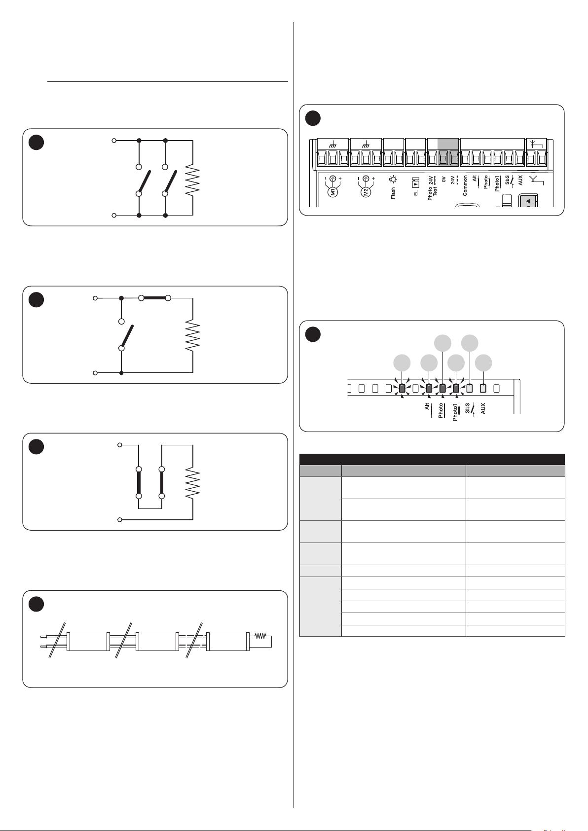
Note 1 One or more NO devices can be connected in parallel
8
9
NO NO
8,2KΩ
8
9
NO
NC
8,2KΩ
8
9
NC NC
8,2KΩ
to one another without any quantity limitation with an 8.2
kΩ termination resistor (“Figure 12”). For electrical connections with the “Stand-by all” function active, refer to
the “Stand-by all / Phototest connection” paragraph.
To connect ALT (STOP) with the “Stand-by all” func-
m
tion active, use terminal no. 5 and not no. 8 (see the
“Stand-by all / Phototest connection” paragraph).
4.3 INITIAL START-UP AND ELECTRICAL
CONNECTIONS TEST
After powering the control unit, carry out the following checks:
1. check that terminals “6-7” have roughly 30 VDC voltage
(“Figure 16”). If the values do not match up, immediately
disconnect the power supply and carefully check the connections and supply voltage.
16
12
Note 2 Multiple devices can be connected as NO and NC con-
tacts in parallel, taking care to place a 8.2 kΩ resistor in
series with the NC contact (this also allows for combining 3 devices: NO, NC and 8.2 kΩ (“Figure 13”).
13
Note 3 One or more NC-type devices can be connected in se-
ries to one another and to an 8.2 kΩ resistor without any
quantity limitation (“Figure 14”).
M M 5 6 7 8 9 10 11 12 131 2 3 4M M
2. after the quick initial ash, the “OK” LED will signal the
correct operation of the control unit by ashing regularly
every second. When there is a variation on the control unit
inputs, the “OK” LED will emit a quick double ash to sig-
nal that the input has been recognised
3. if the connections have been made correctly the “NC”-
type inputs must have the corresponding LED lit, while the
“NO”-type inputs must have the corresponding LED off
(refer to “Figure 17“ and to “Table 4”).
17
L10
L12
L9
OK
L11
L13
14
Note 4 Only one device with 8.2 kΩ xed resistor output can
be connected; if needed, multiple devices must be connected “in cascade” mode with a single 8.2 kΩ termination resistor (“Figure 15”).
15
1 2
8
9
Sensitive
edge
Sensitive
edge
n
Sensitive
edge
8,2kΩ
INPUT-LED MATCHES
Input Type of input LED status
L9 lit
(Only after point 5)
L9 lit
(Only after point 5)
ALT
(STOP)
FOTO
(PHOTO)
FOTO1
(PHOTO1)
Sbs
AUX
ALT (STOP) NC
8.2 kΩ FIXED RESISTOR
STOP
NC L10 lit
NC L11 lit
NO L12 off
PARTIAL OPEN type 1 - NO L13 off
PARTIAL OPEN type 2 - NO L13 off
OPEN ONLY - NO L13 off
CLOSE ONLY - NO L13 off
PHOTO2 - NC L13 lit
Table 4
ENGLISH – 9

4. verify that, when intervening on the devices connected to
1
2 3 4
1
2 3 4
1
O
2 3 4
1
O
2 3 4
1
2 3 4
1
O
2 3 4
1
2 3 4
1
2 3 4
the inputs, the corresponding LEDs switch off or on
5. verify that, when pressing the “[Stop/Set]” button and
[Close
] (“Figure 18”) for over 3 seconds, both the mo-
q
tors complete a brief opening manoeuvre with the upper
leaf motor starting rst. Stop the manoeuvre by pressing
the [Stop/Set] button. LED “L9” (“Figure 17”) must switch
on to signal the correct self-recognition.
SELECTING THE MOTOR TYPE
Motor type Motor selector
O
TOO4524
XME2024
N
O
N
18
If the motors do not start for the opening manoeu-
l
vre, invert the polarity of the motor cables. If the
rst motor to move is not the one associated with
the upper leaf, invert M1 with M2.
If any one of these tests fails, disconnect the pow-
a
er supply to the control unit and check the various
electrical connections made previously.
4.4 MOTOR SELECTOR
The control unit is equipped with a selector (A - “Figure 19”) that
allows for specifying which type of motor to use (see “Table 5”).
4.5 AUTOMATIC LIMIT SWITCH SEARCH AND “STOP” INPUT ACQUISITION
Once the checks have been completed, the automatic search
for mechanical stop devices connected to the control unit can
start. This operation is necessary, as the control unit must detect
the duration of the opening and closing manoeuvres. The procedure is entirely automatic and consists in measuring the motor
effort to detect the mechanical stop devices during the opening
and closing phases.
Before starting the limit switch search, check that
m
all the safety devices give their consent (STOP,
PHOTO and PHOTO1 enabled). The intervention of
a safety device or the arrival of a command during
the procedure causes its immediate interruption.
The leaves MUST be positioned roughly halfway
along their path.
20
19
Any conguration not appearing in “Table 5” is not
m
allowed.
SELECTING THE MOTOR TYPE
Motor type Motor selector
O
Generic
WG2024
WG3524
WG4024
WG5024
TOO3024
N
O
N
N
N
O
N
N
A
Table 5
Press [Stop/Set] and [Close q] (“Figure 20”) for over 3 sec-
onds to start the automatic search phase.
The procedure entails:
– control and memorisation of the motor selector
– control and memorisation of the ALT input (NC / 8.2 kΩ)
– brief opening of both motors
– closing of the lower leaf motor up to the mechanical stop for
the closing phase
– closing of the upper leaf motor up to the mechanical stop for
the closing phase
– start of upper leaf motor opening
– after the programmed offset, start of the lower leaf opening
movement
– the control unit will measure the movement required so that
the motors can reach the mechanical stops for the opening
phase
– the control unit runs the complete closing manoeuvre. The
motors can start at different times. The aim is to have a stag-
gered closing of the leaves so as to avoid potential shearing
between the leaves
– end of the procedure with memorisation of all the measure-
ments recorded.
All these phases occur one after the other, without
m
any intervention by the operator.
If, for any reason, the procedure fails to advance
m
correctly, it must be interrupted by pressing the
[Stop/Set] button. The procedure must then be repeated (if necessary, by modifying the parameters,
for example the amperometric device thresholds
and the leaf delay – consult the “PROGRAMMING”
chapter).
10 – ENGLISH
This procedure can be repeated without having to
l
delete the memory.
5
5 TESTING AND COMMISSIONING
These are the most important phases of the automation’s con-
struction, as they ensure maximum safety of the system. The
test can also be used to periodically verify the devices making
up the automation.
Testing and commissioning of the automation must be per-
formed by skilled and qualied personnel, who are responsible
for the tests required to verify the solutions adopted according
to the risks present, and for ensuring that all legal provisions,
standards and regulations are met, in particular all the requirements of the EN 12445 standard, which denes the test methods for checking gate automations.
The additional devices must undergo specic testing, both in
terms of their functions and their proper interaction with the control unit. Refer to the instruction manuals of the individual devices.
TESTING AND COMMISSIONING
5.1 TESTING
The sequence of steps to be performed when running the testing phase, as described below, refers to a typical system (“Fig-
ure 3”).
To run the test:
1. check that the activation of the STEP-BY-STEP (Sbs) input
triggers the “Open, Stop, Close, Stop” sequence
2. check that the activation of the AUX input (Type 1 partial
opening function) manages the “Open, Stop, Close, Stop”
sequence only for the upper leaf motor. The lower leaf motor must remain still during the closing phase
3. start an opening manoeuvre and verify that:
– when engaging FOTO (PHOTO) the gate continues the
opening manoeuvre
– when engaging FOTO1 (PHOTO1) the manoeuvre
stops until FOTO1 is disengaged. Subsequently, the
manoeuvre will resume the opening movement
– with FOTO2 (PHOTO2), after engaging this device, the
manoeuvre must stop and restart during the closing
phase
4. verify that when the leaf reaches the mechanical stop for
the opening phase, the motors switch off
5. start a closing manoeuvre and verify that:
– when engaging FOTO, the manoeuvre stops and re-
starts during the opening phase
– when engaging FOTO1 (PHOTO1) the manoeuvre
stops until FOTO1 is disengaged. Subsequently, the
manoeuvre will resume the opening movement
– when engaging FOTO2, the gate continues the closing
manoeuvre
6. verify that the stoppage devices connected to the STOP
input cause the immediate stoppage of any movement under way and a brief reversal
7. check that the level of the obstacle detection system is
suited to the application: during the manoeuvre, during
both the opening and closing phases, prevent the leaf’s
movement by simulating an obstacle and verify that the
manoeuvre reverses before exceeding the force specied
in the regulations
8. other checks can be necessary depending on the devices
connected to the inputs.
If an obstacle is detected for two consecutive ma-
a
noeuvres in the same direction, the control unit will
perform a partial reversal of both motors for one
second only. After the next command is given, the
leaves will start opening and the rst intervention of
the amperometric device for each motor will be regarded as a mechanical stop for the opening phase.
The same behaviour occurs when the mains power
supply is restored: the rst command is always an
opening command and the rst obstacle is always
regarded as a mechanical stop for the opening
phase.
5.2 COMMISSIONING
Commissioning can only be performed after all test-
a
ing phases have been successfully completed.
Before commissioning the automation, ensure that
a
the owner is properly informed of all residual risks
and hazards.
To commission the automation:
1. compile the automation’s technical le, which must in-
clude the following documents: overall drawing of the
automation, wiring diagram, risk assessment and relative
solutions adopted, the manufacturer’s declaration of conformity for all devices used and the declaration of conformity compiled by the installer
2. afx a data plate on the gate specifying at least the fol-
lowing data: type of automation, name and address of
the manufacturer (responsible for commissioning), serial
number, year of manufacture and CE mark
3. compile the declaration of conformity of the automation
and hand it to the owner of the automation
4. compile the User Manual of the automation and hand it to
the owner of the automation
5. compile and provide the owner with the automation’s
“Maintenance schedule”, containing the maintenance instructions for all the automation’s devices.
For all the above-mentioned documentation, Nice –
l
through its technical assistance service – provides
the following: pre-completed forms.
6
6 PROGRAMMING
There are 4 buttons on the control unit: [Open p], [Stop/Set],
[Close
both for commanding the control unit during the testing phases
and for programming the available functions.
21
PROGRAMMING
] and [Radio R] (“Figure 21”), which can be used
q
L1 L8
..
LR
The programmable functions available are arranged on two levels and their operating status is signalled by the eight LEDs “L1
... L8” and by the “LR” LED present on the control unit (LED lit =
function active; LED off = function not active).
6.1 USING THE PROGRAMMING BUTTONS
[Open p]:
– Button for commanding the gate opening
– Selection button during the programming phase.
[Stop/Set]:
– Button used to stop a manoeuvre
– If pressed for more than 5 seconds, it allows for entering the
programming mode.
[Close
– Button for commanding the gate’s closure
– Selection button during the programming phase.
q
]
ENGLISH – 11

6.2 PRE-SET FUNCTIONS
The control unit has a few programmable functions, which are
pre-set in a typical conguration that suits most automations (see
“Table 6”). The functions can be modied at any time, both be-
fore and after the automatic limit switch search phase, through
appropriate programming procedures described below.
PRE-SET FUNCTIONS
Function Pre-set value
Automatic closing
Condominium
Pre-ashing
Close after photo
Opening delay
Stand-by all / Phototest
Electric lock / OGI
ALT (STOP) input
Heavy gates
Pause time
Auxiliary input
Amperometric sensitivity
active
disabled
disabled
disabled
level 5 (20%)
Stand-by all
Electric lock
self-recognition NC / 8.2 kΩ
disabled
30 seconds
Type 1 partial opening (activates
upper leaf motor only)
level 3
Table 6
6.3 LEVEL 1 PROGRAMMING (ON-OFF)
All the Level 1 functions are set by default to “OFF” and can be modied at any time. Refer to “Table 7” to check the various func-
tions.
6.3.1 Level 1 programming procedure
The user has maximum 10 seconds to press the buttons consecutively during the programming procedure,
m
after which time the procedure terminates automatically and memorises the changes made up to then.
To perform Level 1 programming:
1. press and hold the [Stop/Set] button until LED “L1” starts ashing
2. press the [Open
] or [Close q] button to move the ashing LED to the LED associated with the function to be modied
p
3. press the [Stop/Set] button to change the status of the function:
– short ash = OFF
– long ash = ON
4. wait 10 seconds (maximum time) to exit the programming mode.
To set other functions to “ON” or “OFF”, while the procedure is running, repeat points 2 and 3 during the phase
l
itself.
LEVEL 1 FUNCTIONS (ON-OFF)
LED Function Description
Function ENABLED: after an opening manoeuvre there is a pause (equal to the set pause time), after
L1 Automatic closing
L2 Close after photo
L3 Always Close
Stand-by /
L4
Phototest
which the control unit automatically starts a closing manoeuvre. The pause time is set by default to 30
seconds. Pressing the [Stop/Set] button or the intervention of the “STOP” input stop the cycle.
Function NOT ENABLED: the system works in “semi-automatic” mode.
Function ENABLED: if the photocells intervene during the opening or closing manoeuvre, the pause
time drops to 4 seconds regardless of the set “pause time”. With “automatic closing” deactivated, if the
photocells intervene during the opening or closing manoeuvre, the “automatic closing” activates with a
4-second “pause time”.
Function ENABLED: in the event of a blackout, even of short duration, 10 seconds after the electricity
is restored the control unit detects that the gate is open and automatically starts a closing manoeuvre,
preceded by 5 seconds of pre-ashing.
Function ENABLED: phototest.
Instead of the “Stand-by all” function, the user can activate the “Phototest” function, which veries
whether the photocells function properly at the start of a manoeuvre. To use this function, the connect the
photocells correctly (see “Figure 7 C”) then activate the function.
Function NOT ENABLED: stand-by.
The control unit has the “Stand-by all” function set by default; if it is active, 1 minute after the end of the
manoeuvre the control unit switches off the “Stand-by all” function (terminal 5), all the inputs and the other
outputs to limit consumption (see “Figure 7 A”). This function is mandatory if the control unit is powered
exclusively through Solemyo photovoltaic panels. It is recommended even if the control unit is powered
from the mains and the user wishes to increase the emergency mode operation with the PS124 back-up
battery.
Table 7
12 – ENGLISH

LEVEL 1 FUNCTIONS (ON-OFF)
LED Function Description
Electric lock /
L5
OGI (Open Gate
Indicator)
L6 Pre-ashing
Condominium
L7
function
L8 Light/Heavy Gates
Function ENABLED: OGI (Open Gate Indicator).
If the function is enabled, terminals 3-4 can be used to connect an open gate indicator light (24 V).
Function NOT ENABLED: electric lock.
If the function is not enabled, terminals 3-4 can be used to connect the electric lock.
Function ENABLED: the warning light starts ashing 3 seconds before the start of the manoeuvre to
signal in advance a dangerous situation.
Function NOT ENABLED: the warning light starts ashing when the manoeuvre starts.
Function ENABLED: each command received triggers an opening manoeuvre that cannot be interrupted
by subsequent command impulses.
Function NOT ENABLED: each command received triggers an OPEN-STOP-CLOSE-STOP sequence,
which is useful when many people use the automation with radio commands.
Function ENABLED: if the function is enabled, the control unit can be congured to control heavy gates
by setting the acceleration ramp and closing slowdown speeds differently.
Function NOT ENABLED: if the function has not been enabled, the control unit is set for controlling light
gates.
6.4 LEVEL 2 PROGRAMMING (ADJUSTABLE PARAMETERS)
All Level 2 parameters are set by default as shown under “GREY” in “Table 8” and can be modied at any time. The parameters
can be adjusted to a value between 1 and 8. To check the value corresponding to each LED, refer to “Table 8”.
6.4.1 Level 2 programming procedure
The user has maximum 10 seconds to press the buttons consecutively during the programming procedure,
m
after which time the procedure terminates automatically and memorises the changes made up to then.
To perform Level 2 programming:
1. press and hold the [Stop/Set] button until LED “L1” starts ashing
2. press the [Open
modied
3. press and hold the [Stop/Set] button. With the [Stop/Set] button pressed:
– wait roughly 3 seconds, until the LED representing the current level of the parameter to be modied lights up
– press the [Open
4. release the [Stop/Set] button
5. wait 10 seconds (maximum time) to exit the programming mode.
] or [Close q] button to move the ashing LED to the “entry LED” associated with the parameter to be
p
] or [Close q] button to shift the LED associated with the parameter’s value
p
To set multiple parameters during the procedure's execution, repeat the operations from point 2 to point 4 dur-
l
ing the phase itself.
The set value highlighted in grey (“Table 8”) indicates that is the default value.
l
LEVEL 2 FUNCTIONS (ADJUSTABLE PARAMETERS)
Entry
LED
L1 Pause Time
Parameter
LED
(level)
L1 5 seconds
L2 15 seconds
L3 30 seconds
L4 45 seconds
L5 60 seconds
L6 80 seconds
L7 120 seconds
L8 180 seconds
Set value Description
Adjusts the pause time, in other words, the time that elapses before
automatic re-closure. It is only effective if the Close function is
enabled.
Table 8
ENGLISH – 13

LEVEL 2 FUNCTIONS (ADJUSTABLE PARAMETERS)
Entry
LED
Parameter
LED
(level)
Set value Description
L1 Type 1 partial open
L2 Type 2 partial open
L3 Open only
L4 Close only
L5 Photo 2
L6 Stop (stops the manoeuvre)
L2 AUX input
L7 Excluded
L8 Excluded
L1 Open: 40%; Close: 40%
L2 Open: 60%; Close: 40%
L3 Open: 80%; Close: 40%
L3 Motor speed
L4 Open: 80%; Close: 60%
L5 Open: 80%; Close: 80%
L6 Open: 100%; Close: 60%
L7 Open: 100%; Close: 80%
L8 Open: 100%; Close: 100%
L1 No discharge
L2 0.2 seconds
L3 0.4 seconds
L4
Motor
discharge after
closing
L4 0.6 seconds
L5 0.8 seconds
L6 1.0 seconds
L7 1.2 seconds
L8 1.4 seconds
L1 Level 1 - Minimum force Adjusts the force of both motors.
L2 Level 2 - ...
L3 Level 3 - ...
L4 Level 4 - ...
L5 Level 5 - ...
L6 Level 6 - ...
L5
Motor force
(amperometric
L7 Level 7 - ...
sensitivity)
L8 Level 8 - Maximum force
L1 0%
L2 5%
L3 10%
L6 Leaf delay
L4 15%
L5 20%
L6 30%
L7 40%
L8 50%
The control unit has an auxiliary input that can be congured with
one of the following 6 functions.
Type 1 partial opening: performs the same function as the STEPBY-STEP input, triggering the opening of the upper leaf only. It
only works with the gate fully closed, otherwise the command is
interpreted as if it were a STEP-BY-STEP command.
Type 2 partial opening: performs the same function as the STEPBY-STEP input, triggering the opening of the two leaves for half the
time it takes for full opening. It only works with the gate fully closed,
otherwise the command is interpreted as if it were a STEP-BY-STEP
command.
Open Only: this input performs opening only with the Open-StopOpen-Stop sequence.
Close Only: this input performs closing only with the Close-StopClose-Stop sequence.
Photo 2: performs the function of the “PHOTO 2” safety device.
Excluded: this input does not manage any function.
Adjusts the motor speed during normal travel.
Adjusts the duration of the “brief reversal” of both motors, after
completing the closing manoeuvre, to reduce the residual nal
thrust.
The control unit features a system that measures the current
absorbed by the two motors and used to detect the mechanical
limit switches and any obstacles during the gate’s movement. As
the absorbed current depends on variable conditions (weight of the
gate, sources of friction, wind gusts, voltage uctuations, etc.), the
intervention threshold can be modied. There are 8 levels: level 1
is the most sensitive level (minimum force), while level 8 is the least
sensitive (maximum force).
Increasing the degree of amperometric sensitivity increases the
slowdown speed during the gate closing manoeuvre.
WARNING! – The suitably adjusted “amperometric” function
(together with other indispensable arrangements) can be
useful to ensure compliance with the EN 12453 and EN 12445
standards, which require the use of techniques or devices that
limit the force and dangerousness associated with automatic
door and gate movements.
Adjust the closing delay for the upper leaf motor.
It is programmed as a percentage of the work time.
The opening delay is half the time of the closing delay.
14 – ENGLISH

LEVEL 2 FUNCTIONS (ADJUSTABLE PARAMETERS)
Entry
LED
L7
L8
Parameter
Maintenance
notication
List of
malfunctions
LED
(level)
L1 500
L2 1000
L3 1500
L4 2500
L5 5000
L6 10000
L7 15000
L8 20000
L1 Result of 1
L2 Result of 2
L3 Result of 3
L4 Result of 4
L5 Result of 5
L6 Result of 6
L7 Result of 7
L8 Result of 8
Set value Description
st
nd
rd
manoeuvre
th
manoeuvre
th
manoeuvre
th
manoeuvre
th
manoeuvre
th
manoeuvre
Adjusts the number of manoeuvres after which
the automation maintenance request is triggered
(see the “Maintenance notication” paragraph).
manoeuvre (most recent)
manoeuvre
Allows for verifying the type of anomaly that
occurred in the last 8 manoeuvres (see “Anomaly
log” paragraph).
6.5 MEMORY DELETION
The procedure described below restores the con-
m
trol unit’s default settings. All the custom settings
will be lost.
22
L1 L8
..
To delete the control unit’s memory and restore all the default
settings, proceed as described below:
1. press and hold the [Open
the programming LEDs “L1-L8” light up (after roughly 3
seconds)
2. release the buttons
3. if the operation was successful, the programming LEDs
“L1-L8” ash quickly for 3 seconds.
The following features will be deleted: STOP cong-
l
uration, limit switch positions, Level 1 and Level 2
programming, number of manoeuvres. The memorised transmitters will not be deleted.
] and [Close q] buttons until
p
6.6.1.1 STANDARD memorisation (Mode 1: all buttons)
Procedures of this kind allow for simultaneously memorising,
during their execution, all the buttons on the transmitter. The
system automatically associates each button with a pre-dened
command, according to the following scheme:
Table 9
TRANSMITTER FUNCTION PAIRINGS
Command Button
1 - Step-by-Step
2 - AUX
3 - OPEN
4 - CLOSE
Will be paired with button 1
Will be paired with button 2
Will be paired with button 3
will be paired with button 4 (if
present on the transmitter).
6.6.1.2 CUSTOM memorisation (Mode 2: one button
only)
Procedures of this kind allow for memorising, during their execution, a single button among those present on the transmitter.
The following commands can be paired with the buttons: Step-
by-Step, AUX, OPEN, CLOSE.
The installer decides which button to associate with the command on the basis of the automation’s needs.
6.6.2 Number of transmitters that can be memorised
The control unit’s receiver has 100 memory locations. A location
can memorise either a single transmitter (i.e. the combination of
its buttons and commands) or a single button with the relative
command.
6.6 MEMORISING THE TRANSMITTERS
The control unit incorporates a radio receiver compatible with all
transmitters that adopt the following NICE radio encoding protocols: FLO, FLOR, O-CODE and SMILO.
6.6.1 Procedure for memorising transmitter buttons
Among the available procedures for memorising transmitters,
some allow for memorising in “standard” mode (or Mode 1) and
others in “custom” mode (or Mode 2).
6.6.3 Transmitter memorisation and deletion procedures
To perform the procedures A, B, C and D described
a
below, the control unit’s memory must be unlocked.
If the memory is locked, perform the unlocking procedure described in the “LOCKING AND UNLOCK-
ING THE MEMORY” paragraph
ENGLISH – 15

23
LR
6.6.3.1 PROCEDURE A - Memorising ALL buttons of a
single transmitter (STANDARD mode or Mode 1)
To perform this procedure:
1. on the control unit: press and hold the [Radio
ton until the “LR” LED lights up
2. release the button [Radio
3. (within 10 seconds) on the transmitter to be memorised:
press and hold any button and wait until the “LR” LED
emits 3 long ashes (= memorisation completed correctly)
4. release the transmitter button.
After the 3 long ashes a further 10 seconds remain
l
to memorise an additional transmitter (if desired),
starting from step 3.
The “LR” LED can also emit the following signals: 1
l
fast ash, if the transmitter is already memorised, 6
ashes, if the transmitter’s radio encoding system
is not compatible with that of the control unit’s receiver, or 8 ashes, if the memory is full.
6.6.3.2 PROCEDURE B - Memorising a SINGLE BUTTON
of a transmitter (CUSTOM mode or Mode 2)
To perform this procedure:
1. choose the command to be paired with the relevant button
to be memorised:
– for no. 1 - “Step-by-Step” press the [Radio
once
– for no. 2 - “AUX” press the [Radio
– for no. 3 - “OPEN” press the [Radio
times
– for no. 4 - “CLOSE” press the [Radio
times
2. on the control unit: press and release the [Radio
button for a number of times corresponding to the desired
command, as shown near the command selected beforehand at step 1.
3. (within 10 seconds) on the transmitter: press and hold
the button to be memorised and wait for the “LR” LED to
emit 3 long ashes (= memorisation completed correctly)
4. release the transmitter button.
After the 3 long ashes a further 10 seconds remain
l
to memorise an additional button (if desired), starting from step 1.
The “LR” LED can also emit the following signals: 1
l
fast ash, if the transmitter is already memorised, 6
ashes, if the transmitter’s radio encoding system
is not compatible with that of the control unit’s receiver, or 8 ashes, if the memory is full.
R
]
] button twice
R
R
R
] but-
R
] button
R
] button 3
] button 4
R
6.6.3.3 PROCEDURE C - Memorising a transmitter by
means of another transmitter already memorised
(memorisation far from the control unit)
This procedure can be used to memorise a new transmitter by
means of a second transmitter, already memorised in the same
control unit. In this way, the new transmitter can receive the
same settings as those of the memorised transmitter. The user
does not have to intervene directly on the control unit’s [Radio
] button, as the procedure is simply carried out within the
R
control unit’s radius of reception.
To perform this procedure:
1. on the transmitter to be memorised: press and hold the
button to be memorised
2. on the control unit: after a few seconds (roughly 5) the
“LR” LED lights up
3. release the transmitter button
4. on the transmitter already memorised: press and slowly
release 3 times the memorised button to be copied
5. on the transmitter to be memorised: press and hold the
same button pressed at point 1 and wait for the “LR” LED
to emit 3 long ashes (= memorisation completed correctly)
6. release the transmitter button.
The “LR” LED can also emit the following signals: 1
l
fast ash, if the transmitter is already memorised, 6
ashes, if the transmitter’s radio encoding system
is not compatible with that of the control unit’s receiver, or 8 ashes, if the memory is full.
6.6.3.4 PROCEDURE D - Deleting a single transmitter
(if memorised in Mode 1) or a single transmitter
button (if memorised in Mode 2)
To perform this procedure:
1. on the control unit: press and hold the [Radio
ton
2. after roughly 4 seconds, the “LR” LED will light up steady
(continue holding down the [Radio
3. on the transmitter to be deleted from the memory:
press and hold a button (*) until the “LR” LED (on the con-
trol unit) emits 5 fast ashes (or 1 ash if the transmitter or
button is not memorised).
4. release the [Radio
(*) If the transmitter is memorised in Mode 1, any button
]
6.6.3.5 PROCEDURE E - Deleting ALL memorised
To perform this procedure:
1. on the control unit: press and hold the [Radio
2. after roughly 4 seconds, the “LR” LED will light up steady
3. after roughly 4 seconds, the “LR” LED will turn off (contin-
4. when the “LR“ LED starts ashing, count 2 ashes and
5. during the deletion process, the “LR” LED will ash rapidly
6. the “LR” LED will emit 5 long ashes to signal that the
can be pressed and the control unit will delete the entire transmitter. If the transmitter is memorised in Mode
2, it is necessary to press the memorised button to be
deleted. To delete further buttons memorised in Mode 2,
repeat the entire procedure for every button to be deleted.
transmitters
ton
(continue holding down the [Radio
ue holding down the [Radio
prepare to release the button precisely during the 3rd
ash that follows
deletion has been completed correctly.
R
] button.
R
R
R
] button
] button
] button
R
R
] but-
] but-
16 – ENGLISH
6.7 LOCKING AND UNLOCKING THE MEMORY
2
WARNING! - This procedure locks the memory, pre-
a
venting the execution of Procedures A, B, C and D
described in the “Transmitter memorisation and de-
letion procedures“ paragraph
24
LR
Procedure for locking/unlocking the memory:
1. disconnect the control unit from the power supply
2. press and hold the [Radio
R
] button
3. power the control unit again (by pressing down the [Radio
] button)
R
4. after 5 seconds the “LR” LED will emit 2 slow ashes
5. release the button [Radio
6. (within 5 seconds) repeatedly press the [Radio
R
]
] but-
R
ton to select one of the following options:
– disabling of the memory lock function = LED off
– enabling of the memory lock function = LED on
7. ve seconds after last pressing the button, the “LR” LED
will emit 2 slow ashes to signal the end of the procedure.
7
7 TROUBLESHOOTING... (troubleshooting guide)
Some devices are congured for signalling the operating status or the presence of any anomalies.
7.1 SIGNALLING THROUGH WARNING LIGHT
If a warning light is connected to the FLASH output on the control unit, the light will ash once every 1 second while the manoeuvre is being performed.
If any anomalies occur, the warning light will emit slow ashes
repeated twice with a 1-second interval. “Table 10” describes
the cause and possible solutions for each type of anomaly signalled by the warning light.
In case of anomaly, the “OK” LED will also emit signals. “Table
10” describes the cause and possible solutions for each type of
anomaly signalled by the “OK” LED.
SIGNALS EMITTED BY THE OK LED (“FIGURE 25”) AND WARNING LIGHT
Flashes Anomaly Possible solution
2 short red ashes
1-second pause
2 short red ashes
3 short red ashes
1-second pause
3 short red ashes
4 short red ashes
1-second pause
4 short red ashes
5 short red ashes
1-second pause
5 short red ashes
6 short red ashes
1-second pause
6 short red ashes
7 short red ashes
1-second pause
7 short red ashes
8 short red ashes
1-second pause
8 short red ashes
(troubleshooting guide)
Intervention of a photocell
Intervention of the
“Obstacle Detection”
function through the force
limiter
Intervention of the ALT
(STOP) input
Error in the internal
parameters of the control
unit
The maximum limit for
consecutive manoeuvres or
manoeuvres per hour has
been exceeded
Electric circuit anomaly
A command that prevents
other commands from being
executed is already present
25
5 6 7 8 9 10 11 12 13
3 4
One or more photocells do not consent to the movement or have caused
the latter to reverse. Check for any obstacles.
During the gate’s movement, the motors encountered more resistance.
Verify the cause and increase the motor force if necessary.
At the start of the manoeuvre or during the movement itself, the ALT (STOP)
input intervened. Identify the cause.
Wait at least 30 seconds then try giving a command and disconnect the
power supply if necessary. If the condition persists, there may be a serious
malfunction and the electronic board needs to be replaced.
Wait for a few minutes until the manoeuvre limiting device drops to under
the maximum limit.
Wait at least 30 seconds then try giving a command and disconnect the
power supply if necessary. If the condition persists, there may be a serious
malfunction and the electronic board needs to be replaced.
Check the type of the “always present” command (for example, it could be
a command from a clock on the AUX input).
TROUBLESHOOTING...
OK
Table 10
ENGLISH – 17

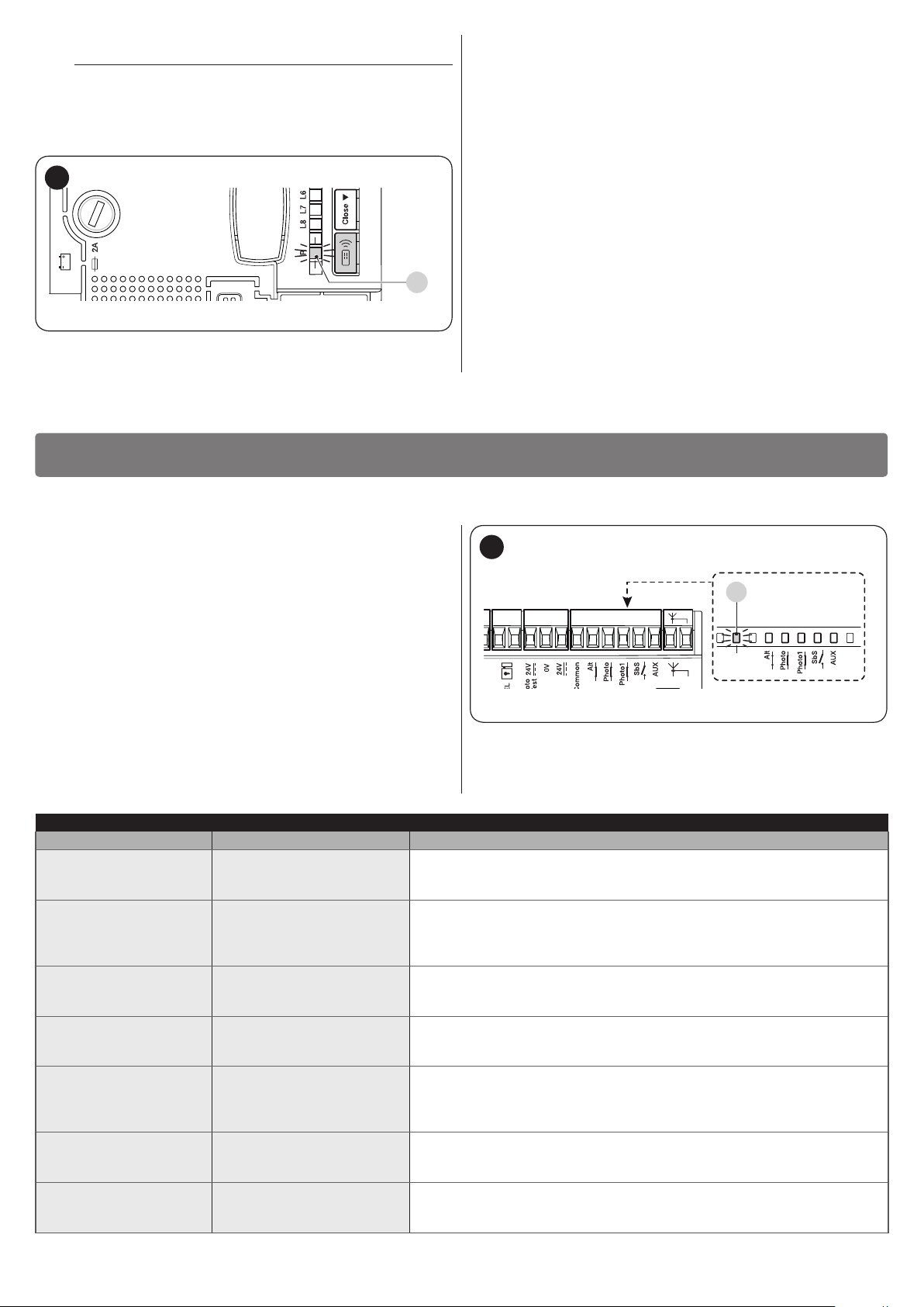
7.2 SIGNALS ON THE CONTROL UNIT
The control unit has LEDs “L1-L8” on the buttons and LEDs “L9-
L13” and the “OK” LED on the control unit terminals (“Figure
26”).
Each of these LEDs can emit special signals, both during normal operation and in case of anomalies. “Table 11” and “Table
12” describe the cause and possible solution for every type of
anomaly.
SIGNALS OF THE LED ON THE CONTROL UNIT TERMINALS
Status Meaning Possible solution
All LEDs
Check whether the control unit is powered: measure on terminals 6-7 a
No LED is lit No power to the control unit
voltage of roughly 30 VDC (or 24 VDC if battery-powered).
Check the 2 fuses; if the OK LED is also not lit nor ashes, there may be a
serious fault, therefore the control unit must be replaced.
OK LED
Make sure there is power supply; verify whether the fuses are blown; if
OFF Anomaly
necessary, identify the reason for the failure then replace the fuses with
others of the same type
There is a serious anomaly; try switching off the control unit for a few
On Serious anomaly
seconds; if the condition persists, it means there is a fault and the circuit
board needs to be replaced
1 ash per second All OK
1 ash every 5 seconds All OK
2 quick ashes
The status of the inputs has
changed
The control unit works normally
Control unit in stand-by mode
This is normal when there is a change affecting one of the inputs: OPEN,
STOP, intervention of the photocells, or when the radio transmitter is used
Series of ashes
separated by a one-
Various This is the same signal as the one on the warning light (see “Table 10”)
second pause
STOP LED
OFF
Intervention of the ALT
(STOP) input
On All OK
Check the devices connected to the STOP input
STOP Input active
PHOTO LED
OFF
Intervention of the PHOTO
input
On All OK
Check the devices connected to the PHOTO input
PHOTO input active
PHOTO1 LED
OFF
Intervention of the PHOTO1
input
On All OK
Check the devices connected to the PHOTO1 input
PHOTO1 input active
Sbs LED
OFF All OK
On Intervention of the Sbs input
Sbs input not active
Normal if the device connected to the Sbs input is active
AUX LED
OFF All OK
On
Intervention of the AUX
input
AUX input not active
Normal if the device connected to the AUX input is active
26
6 7 8 9 10 11 12 13
L1 L8
..
OK
L9
L10
L11
L12
L13
Table 11
18 – ENGLISH
SIGNALS OF THE LED ON THE CONTROL UNIT BUTTONS
Status Meaning
L1 LED
OFF
On
Flashes
L2 LED
OFF
On
Flashes
L3 LED
OFF
On
Flashes
LED L4
OFF
On
Flashes
LED L5
OFF
On
Flashes
LED L6
OFF
On
Flashes
LED L7
OFF
On
Flashes
LED L8
OFF
On
Flashes
During normal operation, it signals that the “Automatic closing” mode is not active
During normal operation, it signals that the “Automatic closing” mode is active
Function programming in progress
During normal operation, it signals that the “Close after photo” mode is not active
During normal operation, it signals that the “Close after photo” mode is active
Function programming in progress
During normal operation, it signals that the “Always Close” mode is not active
During normal operation, it signals that the “Always Close” mode is active
Function programming in progress. If it ashes together with LED L4, the position recognition phase must be carried out
(see the “Automatic limit switch search and “STOP” input acquisition” paragraph)
During normal operation, it signals that the “Stand-by” mode is active
During normal operation, it signals that the “Phototest” mode is active
Function programming in progress. If it ashes together with LED L3, the position recognition phase must be carried out
(see the “Automatic limit switch search and “STOP” input acquisition” paragraph)
During normal operation, it signals the OGI output as OGI (open gate indicator)
During normal operation, it signals the OGI output as ELS (electric lock)
Function programming in progress
During normal operation it signals that the “Pre-ashing” mode is not active
During normal operation it signals that the “Pre-ashing” mode is active
Function programming in progress
During normal operation, it signals that the “Condominium” mode is not active
During normal operation, it signals that the “Condominium” mode is active
Function programming in progress
During normal operation, it signals that the “Light gates” mode is active
During normal operation, it signals that the “Heavy gates” mode is active
Function programming in progress
Table 12
7.3 MAINTENANCE NOTIFICATION
The control unit allows for notifying the user when to perform
maintenance on the automation. The signal is emitted once the
number of manoeuvres completed equals the value set for the
“Maintenance warning” adjustable parameter (see the “Table 8”
paragraph).
The maintenance request signal is emitted through the FLASH
warning light.
The FLASH warning light and the maintenance indicator emit the
signals indicated in “Table 13” based on the number of manoeu-
vres completed with respect to the set limit.
Table 13
MAINTENANCE SIGNALS
Number of manoeuvres
Below 80% of
the limit
Between 81%
and 100% of the
limit
Over 100% of
the limit
Signal on “Flash”
Normal (0.5 s on, 0.5 s
off)
At the start of the
manoeuvre, it remains
lit for 2 s then continues
normally
At the start and end of
the manoeuvre, remains
lit for 2 s then continues
normally
Signal on maintenance indicator
On for 2 s at the
start of opening
Flashes
throughout the
manoeuvre
Flashes always
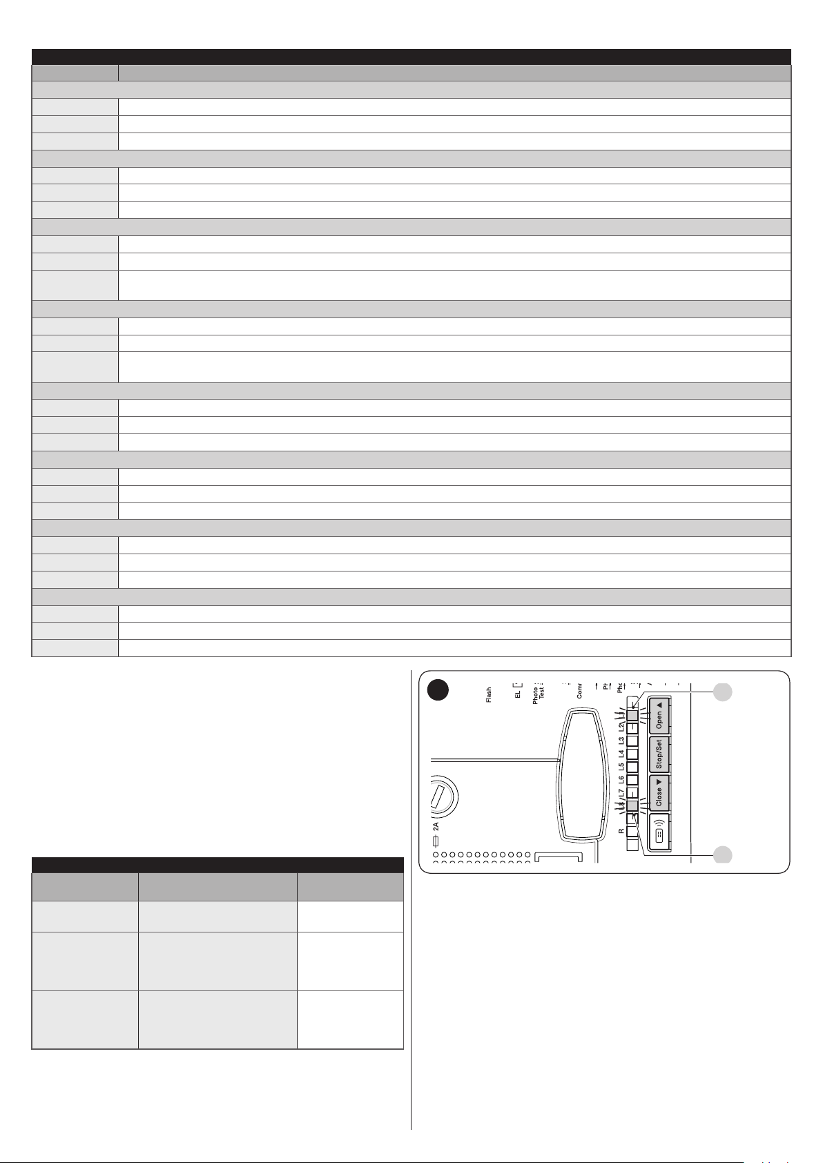
7.4 ANOMALY LOG
The control unit can display any anomalies that have occurred
in the last 8 manoeuvres (for example, the interruption of a manoeuvre due to the intervention of a photocell or sensitive edge).
27
L1
L8
To check the list of anomalies:
1. press and hold the [Stop/Set] button for roughly 3 sec-
onds
2. release the [Stop/Set] button when the “L1” LED starts
ashing
3. press and release the [Open
] or [Close q] button to
p
shift ashing of the LED to “L8” (“Anomaly list” parameter)
4. keep the [Stop/Set] button pressed down (it must be kept
pressed throughout phases 5 and 6)
5. wait roughly 3 seconds, after which LED “L1” – corre-
sponding to the outcome of the last manoeuvre – will light
up
6. press and hold the [Open
] or [Close q] button to se-
p
lect the desired manoeuvre: the corresponding LED will
emit the same number of ashes as those normally emitted by the warning light after an anomaly (see “Table 10”)
7. release the [Stop/Set] button.
ENGLISH – 19
8
A
8 FURTHER INFORMATION (Accessories)
8.1 CONNECTING AN SM-TYPE RADIO RECEIVER
The control unit has a slot for mounting radio receivers with SM
connector (optional accessories) belonging to the SMXI and
OXI families, which can be used to remotely control the control
unit through transmitters that intervene on the unit’s inputs.
f
To install a receiver (“Figure 28”):
1. remove the cover of the control unit’s containment box
2. insert the receiver (A) in the appropriate slot (B) on the
3. put the cover of the control unit’s containment box back
At this stage, the control unit can be powered again.
28
(Accessories)
Before installing a receiver, disconnect the power
supply to the control unit.
control unit’s electronic board
on.
B
A
FURTHER INFORMATION
29
3. place the interface (B) in the appropriate slot (C) on the
control unit’s electronic board
4. insert the cable (D) in the appropriate slot (E) on the in-
terface.
30
B C
“Table 14” shows the receiver outputs and the control unit inputs
associated with each.
Table 14
SMXI / SMXIS OR OXI / OXIFM / OXIT / OXITFM IN MODE 1 OR MODE
2
Receiver output Control unit input
Output No. 1
Output No. 2
Output No. 3
Output No. 4
For further information, consult the specic manual
l
of the receiver.
Step-by-Step
AUX (pre-set value: Partial open 1)
“Open Only”
“Close Only”
8.2 CONNECTING THE IBT4N INTERFACE
The control unit is equipped with a “IBT4N”-type connector for
the IBT4N interface, which allows for connecting all devices
equipped with BusT4 interface, such as, for example, Oview
programmers and the IT4WIFI Wi-Fi interface.
The Oview programmer allows for comprehensively and rapidly
managing the installation, maintenance and diagnosis of the entire automated system.
Before connecting the interface, disconnect the
f
power supply to the control unit.
To install the interface (“Figure 29” and “Figure 30”):
1. remove the cover of the control unit’s containment box
2. remove the plastic pre-cut element (A) and check that
there are no burrs
DE
At this stage, the control unit can be powered again.
For further information, consult the specic manu-
l
als of the connected devices.
8.3 CONNECTING THE PS124 BACK-UP BATTERY
The control unit is congured for being powered with PS124
back-up batteries that intervene in case of a power outage.
Before installing a back-up battery, disconnect the
f
power supply to the control unit.
Before installing and connecting the back-up battery:
1. remove the cover of the control unit’s containment box
2. loosen the screw (A) and turn the panel (B)
31
A B
20 – ENGLISH
3. position the battery (C)
4. insert the connector (D) through the opening (E) and con-
nect it to the slot (F)
5. close the panel (B)
The “Solemyo” system can only be used if the
a
“Stand-by all” function is enabled (ON) on the control unit and if the connections are made as shown
in the diagram (A) in “Figure 7”.
32
C
F
D
B
E
6. remove the pre-cut element (G) and insert the connector
(H) into the slot located under the pre-cut element
33
9
9 PRODUCT MAINTENANCE
Being an electronic part, the control unit does not require any
special maintenance. Nonetheless, the system should be reg-
ularly checked to ensure that it works efciently at least every
6 months according to the instructions in the “TESTING AND
COMMISSIONING” chapter.
10
10 PRODUCT DISPOSAL
l
As with the installation, only qualied personnel must dismantle
the product at the end of its life.
This product is composed of different types of materials. Some
of these materials can be recycled; others must be disposed of.
Please enquire about the recycling or disposal systems in place
in your local area for this type of product.
a
PRODUCT MAINTENANCE
PRODUCT DISPOSAL
This product is an integral part of the operator and
must therefore be disposed of with it.
WARNING
Some parts of the product may contain polluting or
dangerous substances. If not disposed of correctly,
these substances may have a damaging effect on
the environment and human health.
G
H
7. put the cover of the control unit’s containment box back
on.
At this stage, the control unit can be powered again.
8.4 CONNECTING THE SOLEMYO SYSTEM
The control unit is congured for being powered with the “Solemyo” photovoltaic system (photovoltaic panel and 24 V battery).
To connect the Solemyo battery to the control unit, remove the
pre-cut element (A) and use the same connector normally used
for the back-up battery.
34
As indicated by the symbol shown
l
here, this product must not been
disposed of with household
waste. Separate the waste for disposal and recycling, following the
methods stipulated by local regulations, or return the product to
the seller when purchasing a new
product.
WARNING
a
Local regulations may impose heavy penalties if
this product is not disposed of in compliance with
the law.
A
When the automation is powered through the “Sole-
a
myo” system, IT MUST NOT BE POWERED through
the mains electricity at the same time.
ENGLISH – 21

11
EU Declaration of Conformity
Note - The contents of this declaration correspond to declarations in the ofcial document deposited at the registered ofces of Nice S.p.a. and in particular to the last revision available before
printing this manual. The text herein has been re-edited for ed
Number:
Manufacturer’s Name:
Address:
Authorized Person to constitute
technical documentation:
Type of product:
Model/Type:
Accessories:
The
provisions
laid
•Directive
The
•
It
essential
requirements
The
while
maintaining full rights to the related intellectual property.
Should
obliged
to arrange for the relative translation to accompany this declaration.
The
of
directive 2006/42/EC.
The
EN 60335-1:2012+A11:2014, EN 62233:2008, EN 60335-2-103:2015
Oderzo, 05/09/2017
Ing. Roberto Griffa
Ofcer)
11 TECHNICAL SPECIFICATIONS
l
TECHNICAL SPECIFICATIONS
All technical specications stated in this section refer to an ambient temperature of 20°C (± 5°C). Nice S.p.A.
reserves the right to apply modications to the product at any time when deemed necessary, without altering
its functions and intended use.
TECHNICAL SPECIFICATIONS
Description Technical specication
Mains power supply
Maximum power input
Emergency power supply
Maximum motor current
Services power output 24 Vc maximum current 200 mA (the voltage may vary between 16 V and 33 Vc)
Phototest output 24 Vc maximum current 100 mA (the voltage may vary between 16 V and 33 Vc)
Warning light output
Electric lock output
ALT (STOP) input
Work time
Pause time
Discharge time
Leaf opening delay
Leaf closing delay
1st motor output
2nd motor output
Max length of cables
Radio receiver
Operating temperature
Protection rating
Dimensions (mm)
Weight (kg)
Control unit MC424L: 230 Va ± 10% 50–60 Hz; fuse: 1A type T
Control unit MC424L/V1: 120 Va ± 10% 50–60 Hz; fuse: 2A type T
Control unit MC424L/AU01: 250 Va ± 10% 50–60 Hz; fuse: 1A type T
170 W
congured for PS124 back-up batteries and for the Solemyo solar power kit
3 A (with “level 6” amperometric device intervention)
for 24 V c warning lights, maximum power 25 W (the voltage may vary between 16 V and 33 Vc);
for Nice ELDC and EL24 warning lights
for 24 V c lamps, maximum power 5 W (the voltage may vary between 16 V and 33 V c) or for 12 V
a electric locks, 15 VA
for NC contacts or 8.2 kΩ xed resistor +/– 25%
measured automatically
settable
settable
settable
measured automatically
for WINGO motors (WG2024, WG3524, WG4024, WG5024), TOO (TOO3024, TOO4524), SFAB
(XME2024)
for WINGO motors (WG2024, WG3524, WG4024, WG5024), TOO (TOO3024, TOO4524), SFAB
(XME2024)
power supply: 30 m
Solemyo solar kit power supply: 3 m
motors: 10 m
other inputs/outputs: 30 m
warning light: 10 m
OGI: 30 m
electric lock: 10 m
antenna: 20 m (recommended below 3 m)
“SM”-type connector for SMXI, SMXIS, OXI receivers (Mode 1 and Mode 2)
from –20°C to +55°C
IP 54 (with container intact)
310 x 232 x H 122
4,1
Table 15
12
12 CONFORMITY
22 – ENGLISH
CONFORMITY
and declaration of incorporation of “partly completed machinery”
296/MC424 Rev: 5 Language: EN
Via Pezza Alta 13, Z.I. Rustignè, 31046 Oderzo (TV) Italy
MC424, MC424L
undersignedRobertoGriffa,intheroleofChiefExecutiveOfcer,declaresunderhissoleresponsibilitythattheproductdescribedabovecomplieswiththe
downinthefollowingdirectives:
productalsocomplieswiththefollowingdirectivesaccordingtotherequirementsenvisagedfor“partlycompletedmachinery”(AnnexII,part1,sectionB):
Directive 2006/42/EC of the EUROPEAN PARLIAMENT AND COUNCIL of 17 May 2006 related to machinery and amending the Directive 95/16/EC (recast).
ishereby statedthat therelevanttechnical documentationhasbeen compiledin accordancewithannex VIIBof Directive2006/42/EC andthatthe following
manufacturerundertakestotransmittothenationalauthorities,inresponsetoareasonedrequest,therelevantinformationonthe“partlycompletedmachinery“,
“partlycompletedmachinery”must notbeuseduntilthenal machineinwhichitis incorporatedisinturndeclaredas compliant,ifapplicable,withthe provisions
productalsocomplieswiththefollowingstandards:
Refer to the catalog
2014/30/EU(EMC),accordingtothefollowingharmonizedstandards:EN61000-6-2:2005,EN61000-6-3:2007+A1:2011
havebeenfullled:1.1.1-1.1.2-1.1.3-1.2.1-1.2.6-1.5.1-1.5.2-1.5.5-1.5.6-1.5.7-1.5.8-1.5.10-1.5.11
the“partlycompletedmachinery”beputintoserviceinaEuropeancountrywithanofciallanguageotherthanthatusedinthisdeclaration,theimporteris
Nice s.p.a.
Comand central a 2 motor 24V dc
Nice s.p.a.
itorial purposes. A copy of the original declaration can be requested from Nice S.p.a. (TV) I.
(ChiefExecutive

&
INSTRUCTIONS AND WARNINGS FOR THE USER
Before using the automation for the rst time, ask the installer to
explain the origin of any residual risks and take a few minutes
to read this instruction manual and warnings for the user given
to you by the installer. Store the manual for future reference and
hand it to the new owner when transferring the automation.
WARNING!
a
Your automation is a machine that faithfully executes commands imparted by the user. Negligence
and improper use may lead to dangerous situations:
– do not manoeuvre the gate if there are people, animals
or objects within its range of operation
– it is strictly forbidden to touch parts of the automation
while the gate or door is moving
– the photocells are not a safety device but only an aux-
iliary aid to safety. They are built using highly reliable
technology but, in extreme conditions, may malfunction
or even become defective. In certain cases, the defect
may not be clearly evident. For these reasons, it is important to follow all the instructions given in this manual
when using the automation
– periodically check that the photocells work properly.
IT IS STRICTLY FORBIDDEN to transit through the
a
gate while it is closing! It is only possible to transit
through the gate when it is fully open and the leaves
are at a standstill.
CHILDREN
a
An automation system guarantees a high degree
of safety. With its detection systems, it can control
and guarantee the gate’s movement in the presence
of people or objects. It is nonetheless advisable to
forbid children from playing near the automation
and not to leave remote controls near them to prevent any unwanted activation of the system. The automation is not a toy!
The product is not intended for use by persons, including children, with limited physical, sensory or
mental capacities, or who lack experience or knowledge, unless supervised or trained in the use of the
product by a person responsible for their safety.
Anomalies: if the automation appears to behave strangely,
disconnect the power supply to the automation and manually
unlock the motor (consult the respective instruction manual) to
manoeuvre the gate manually. Do not perform any repairs personally, but contact your trusted installer.
Safety devices out of order: the automation can also be used
when one or more safety devices are defective or out of order.
The gate can be operated in the “Person present” mode in the
following way:
1. send a command to operate the gate, with a transmitter
or key selector, etc. If everything works properly, the gate
will move normally, otherwise proceed as described below
2. within 3 seconds, press the control again and hold it down
3. after roughly 2 seconds, the gate will move in the “Person
present” mode, in other words, it will continue moving so
long as the control is held down.
If the safety devices are out of order, have the sys-
m
tem repaired as soon as possible by a qualied
technician.
The test, periodic maintenance and any repairs must be documented by the person carrying out the work and the documents
must be stored by the owner of the automation. The only interventions the user may carry out periodically include cleaning of
the photocell glass components (use a soft and slightly damp
cloth) and removing any leaves or stones that may obstruct the
automation.
The user of the automation must manually unlock
m
the motor before starting any maintenance operation, to prevent other people from accidentally manoeuvring the gate (consult the respective instruction manual).
Maintenance: in order to ensure constant levels of safety and
the longest useful life for the automation, routine maintenance
must be carried out (at least every 6 months).
Only qualied personnel is authorised to carry out
l
checks, maintenance operations and repairs.
Disposal: at the end of its useful life, the automation must be
dismantled by qualied personnel and the materials must be
recycled or disposed of in compliance with the local regulations
in force.
If the automation was locked using the “Lock auto-
l
mation” command, the gate will not move when a
command is sent and the warning light will emit 9
short ashes.
Do not modify the system or the programming and
l
adjustment parameters of the control unit: your installer is exclusively responsible for these operations.
Failure or power outage: while waiting for your installer to in-
tervene or the power supply to be restored, if the system is not
equipped with back-up batteries, the automation can be used
by manually unlocking the motor (consult the relative instruction
manual) and manually moving the gate leaf.
&
ENGLISH – 23

NOTES
&
24 – ENGLISH
&

NOTES
ENGLISH – 25

Nice SpA
Via Pezza Alta, 13
31046 Oderzo TV Italy
info@niceforyou.com
IDV0619A00EN_18-07-2018
www.niceforyou.com
 Loading...