


MBar / LBar
EN - Instructions and warnings for installation and use
IT - Istruzioni ed avvertenze per l’installazione e manuale per l’uso
FR - Instructions et avertissements pour l’installation et l’utilisation
ES - Instrucciones y advertencias para la instalación y el uso
DE - Installierungs-und Gebrauchsanleitungen und Hinweise
PL - Instrukcje i ostrzeżenia do instalacji i użytkowania
NL - Aanwijzingen en aanbevelingen voor installatie en gebruik
Automatic barrier
0682
M3BAR
M5BAR
M7BAR
LBAR


ENGLISH
Original instructions
WARNINGS AND GENERAL PRECAUTIONS
1
English – 1
EN
Contents
Chapter 1 - WARNINGS AND GENERAL PRECAUTIONS
1.1 - Safety instructions . . . . . . . . . . . . . . . . . . . . . . . . . . . . . . . . . . . . . . . . 1
1.2 - Installation warnings . . . . . . . . . . . . . . . . . . . . . . . . . . . . . . . . . . . . . . . 1
1.3 - Special warnings related to European Directives applicable to the
product . . . . . . . . . . . . . . . . . . . . . . . . . . . . . . . . . . . . . . . . . . . . . . . . . . . . . 1
1.3.1 - Installation criteria and special warnings related to
essential requirements . . . . . . . . . . . . . . . . . . . . . . . . . . . . . . . . . . . . . . . . 2
Chapter 2 - PRODUCT DESCRIPTION AND INTENDED USE . . . . . . . . 3
Chapter 3 - INSTALLATION
3.1 - Preliminary checks for installation . . . . . . . . . . . . . . . . . . . . . . . . . . . . . 3
3.2 - Product application limit . . . . . . . . . . . . . . . . . . . . . . . . . . . . . . . . . . . . 3
3.2.1 - Product durability . . . . . . . . . . . . . . . . . . . . . . . . . . . . . . . . . . . . . . 3
3.3 - Typical system . . . . . . . . . . . . . . . . . . . . . . . . . . . . . . . . . . . . . . . . . . . 4
3.3.1 - Modifying the factory settings of the Closure manoeuvre . . . . . . . . 4
3.3.2 - Identification of the spring anchoring holes . . . . . . . . . . . . . . . . . . . 4
3.4 - Barrier lift fixture . . . . . . . . . . . . . . . . . . . . . . . . . . . . . . . . . . . . . . . . . . 5
3.4.1 - If the support surface already exists . . . . . . . . . . . . . . . . . . . . . . . . 5
3.4.2 - If the support surface does not exist . . . . . . . . . . . . . . . . . . . . . . . 5
3.5 - Pole installation . . . . . . . . . . . . . . . . . . . . . . . . . . . . . . . . . . . . . . . . . . 5
3.5.1 - Pole support assembly . . . . . . . . . . . . . . . . . . . . . . . . . . . . . . . . . . 5
3.5.2 - Pole assembly (3 metres / 5 metres) . . . . . . . . . . . . . . . . . . . . . . . . 5
3.5.3 - Pole assembly (6 metres / 9 metres) . . . . . . . . . . . . . . . . . . . . . . . . 6
3.6 - Manually releasing and locking the gearmotor . . . . . . . . . . . . . . . . . . . 6
3.6.1 - How to move the locking cylinder for manual release and lock . . . . 6
3.7 - Mechanical stop adjustment . . . . . . . . . . . . . . . . . . . . . . . . . . . . . . . . . 6
3.8 - Pole balancing . . . . . . . . . . . . . . . . . . . . . . . . . . . . . . . . . . . . . . . . . . . 6
3.8.1 - M3BAR / M5BAR / M7BAR Pole balancing . . . . . . . . . . . . . . . . . . 6
3.8.2 - LBAR Pole balancing . . . . . . . . . . . . . . . . . . . . . . . . . . . . . . . . . . . 6
Chapter 4 - ELECTRICAL CONNECTIONS
4.1 - Description of the electrical connections . . . . . . . . . . . . . . . . . . . . . . . . 6
4.2 - Initial start-up and electrical connections . . . . . . . . . . . . . . . . . . . . . . . 7
4.3 - Pre-set functions . . . . . . . . . . . . . . . . . . . . . . . . . . . . . . . . . . . . . . . . . 7
4.4 - Recognition of the connected devices . . . . . . . . . . . . . . . . . . . . . . . . . 7
4.5 - Recognition of limit positions on opening and closing . . . . . . . . . . . . . . 7
4.6 - Pole movement check . . . . . . . . . . . . . . . . . . . . . . . . . . . . . . . . . . . . . 7
4.7 - Connecting a radio receiver . . . . . . . . . . . . . . . . . . . . . . . . . . . . . . . . . 8
4.8 - Connecting the pole lights (optional accessory) . . . . . . . . . . . . . . . . . . 8
4.9 - Connecting the LED flashing light mod. XBA7 or traffic light to
LED mod. XBA8 (optional accessories) . . . . . . . . . . . . . . . . . . . . . . . . . . . . . 8
4.10 - Connection of other devices . . . . . . . . . . . . . . . . . . . . . . . . . . . . . . . . 8
4.10.1 - Programming unit Oview . . . . . . . . . . . . . . . . . . . . . . . . . . . . . . . 8
4.10.2 - Buffer battery mod. PS224 (accessory) . . . . . . . . . . . . . . . . . . . . 8
4.10.3 - Solemyo System (photovoltaic supply) . . . . . . . . . . . . . . . . . . . . . 8
Chapter 5 - TESTING AND COMMISSIONING
5.1 - Testing . . . . . . . . . . . . . . . . . . . . . . . . . . . . . . . . . . . . . . . . . . . . . . . . . 9
5.2 - Commissioning . . . . . . . . . . . . . . . . . . . . . . . . . . . . . . . . . . . . . . . . . . 9
Chapter 6 - CONTROL UNIT PROGRAMMING
6.1 - Level one programming (ON-OFF functions) . . . . . . . . . . . . . . . . . . . . 10
6.2 - Level two programming (adjustable parameters) . . . . . . . . . . . . . . . . . 10
Chapter 7 - FURTHER INFORMATION
7.1 - Total deletion of control unit memory . . . . . . . . . . . . . . . . . . . . . . . . . 12
7.2 - Other functions . . . . . . . . . . . . . . . . . . . . . . . . . . . . . . . . . . . . . . . . . . 12
7.3 - Adding or removing devices . . . . . . . . . . . . . . . . . . . . . . . . . . . . . . . . 13
7.3.1 - Bluebus Inlet . . . . . . . . . . . . . . . . . . . . . . . . . . . . . . . . . . . . . . . . 13
7.3.2 - Photocells . . . . . . . . . . . . . . . . . . . . . . . . . . . . . . . . . . . . . . . . . . 13
7.3.3 - MOTB digital selector and proximity reader for
MOMB transponder cards . . . . . . . . . . . . . . . . . . . . . . . . . . . . . . . . . . . . 13
7.3.4 - STOP Input . . . . . . . . . . . . . . . . . . . . . . . . . . . . . . . . . . . . . . . . . 13
7.4 - Diagnostics . . . . . . . . . . . . . . . . . . . . . . . . . . . . . . . . . . . . . . . . . . . . 14
7.4.1 - Signals of control unit . . . . . . . . . . . . . . . . . . . . . . . . . . . . . . . . . . 14
7.4.2 - Flashing light signals . . . . . . . . . . . . . . . . . . . . . . . . . . . . . . . . . . 16
7.5 - Loop Detector . . . . . . . . . . . . . . . . . . . . . . . . . . . . . . . . . . . . . . . . . . 16
7.5.1 - Operation . . . . . . . . . . . . . . . . . . . . . . . . . . . . . . . . . . . . . . . . . . . 16
7.5.2 - Installation . . . . . . . . . . . . . . . . . . . . . . . . . . . . . . . . . . . . . . . . . . 16
7.6 - Master - Slave mode . . . . . . . . . . . . . . . . . . . . . . . . . . . . . . . . . . . . . 18
7.6.1 - Installation and electrical connections . . . . . . . . . . . . . . . . . . . . . . 18
Chapter 8 - WHAT TO DO IF... (troubleshooting guide) . . . . . . . . . . . . .19
PRODUCT DISPOSAL . . . . . . . . . . . . . . . . . . . . . . . . . . . . . . . . . . . . . . . 19
TECHNICAL CHARACTERISTICS OF THE PRODUCT . . . . . . . . . . . . . 20
Declaration of Conformity: appendix I (removable appendix) . . . . . . . . 21
Declaration of Conformity: appendix II (removable appendix) . . . . . . . . 22
Operation manual (removable appendix) . . . . . . . . . . . . . . . . . . . . . . . . . . A
Maintenance schedule (removable appendix) . . . . . . . . . . . . . . . . . . . . . . B
PICTURES . . . . . . . . . . . . . . . . . . . . . . . . . . . . . . . . . . . . . . . . . . . . . I - XVIII
1.1 - Safety instructions
• CAUTION! – This manual contains important instructions and warnings for personal safety. Incorrect installation could cause serious physical
injury. We recommend that you read this entire manual with care before starting any work. If in doubt, do not install the product and contact the Nice technical assistance department.
• CAUTION! – Important instructions: keep this manual in a safe place
to enable future product maintenance and disposal operations.
1.2 - Installation warnings
• Before commencing installation, check that the product is suitable for the
intended kind of use (see paragraph 3.1 and 3.2).If not suitable, do NOT proceed with installation.
• The contents of this manual refer to a standard system such as that shown in
fig. 1.
Considering the risk situations that may arise during installation phases and
use of the product, the automation must be installed in observance of the following warnings.
- On the power line to the system, install a device for disconnection from the
power mains with a gap between contacts that assures complete disconnection in the conditions of overvoltage category III.
- All product installation and maintenance operations must be performed with
the automation disconnected from the power mains. If the power disconnect
device is not visible from the location of the automation, before starting working, a suitable notice must be affixed on the power disconnect device stating
“WARNING! MAINTENANCE IN PROGRESS”.
- Connect the product to an electric power line equipped with an earthing
system.
- During installation, handle the automation with care to avoid crushing, impact,
dropping or contact with liquids of any type. Never place the product near
sources of heat or expose to naked flames. This may damage product components and cause malfunctions, fire or hazardous situations. If this occurs, suspend installation immediately and contact the Nice Service Centre.
- Never make modifications to any part of the product. Operations other than
as specified can only cause malfunctions. The manufacturer declines all liability for damage caused by makeshift modifications to the product.
- This product is not designed to be used by persons (including children)
whose physical, sensorial or mental capacities are reduced, or with lack of
experience or skill, unless suitable instructions regarding use of the product
have been provided by a person responsible for safety.
- The product may not be considered an efficient system of protection
against intrusion. If an efficient protection system is required, the automation
must be integrated with other safety devices.
- Do not allow children to play with fixed control devices. Keep remote control
devices out of reach of children.
- The road barrier cannot be used before it has been commissioned as specified in chapter 5 “Testing and commissioning”.
- The product’s packaging materials must be disposed of in full compliance
with local regulations.
1.3 - Special warnings related to European Directives applica-
ble to the product
• “Construction Products” Directive:
Special warnings related to 89/106/EEC “Construction Products” Directive
and subsequent modification 98/38/EEC applicable to the product:
- Complete installation of this product, as described in this instruction manual and for certain types of use (for example excluding exclusive use for vehicles) may class it in the field of application of the Directive “Construction
Products” 89/106/EEC and relative harmonised standard EN 13241-1.
- Paragraph 1.3.1 specifies all installation criteria required to ensure that the
pro duct complies with the essential requirements of the directive 89/106/EEC;
the installer should check and ensure that all these criteria are strictly
observed.
- Failure to observe one or more of these criteria may mean that the road barrier may not meet all the essential requirements. Use of the product in
these situations is strictly prohibited until all the directive requirements are met; in this case, the label “ES13241-1.4870” applied on the
product must be removed and the “EC declaration of Conformity” in appendix I of this manual may not be used. As a consequence, the installer in turn
becomes the manufacturer of the “automatic barrier”, and must therefore
observe all the requirements of the Directive “Construction Products”
89/106/EEC and relative harmonised standard EN 13241-1. In this case the
road barrier must be considered as “any machine” and the “Declaration of
conformity” in appendix II may be used (for insertion in the technical documentation).
• “Machinery Directive”:
- Paragraph 1.3.1 specifies all installation criteria required to ensure that the
product complies with the essential requirements of the “Machinery directive”
2006/42/EC (ex 98/37/EC). The installer should check and ensure that all
these criteria are strictly observed.
- Failure to observe one or more of these criteria may mean that the road bar-

TABLE 1 - Essential requirements for CE marking (according to prospect ZA.1 of standard EN 13241-1)
Essential requirements Point of standard Result
Resistance to water 4.4.2 NPD*
Release of hazardous substances 4.2.9 Compliant
Resistance to wind load 4.4.3 Compliant
Heat resistance 4.4.5 NPD*
Permeability to air 4.4.6 NPD*
Safe opening for vertically moving doors 4.2.8 Compliant
Definition of the geometry of glass components 4.2.5 NPD*
Mechanical strength and stability 4.2.3 Compliant
Manoeuvring forces for power-operated doors/gates 4.3.3 Compliant
Durability of resistance to water, heat resistance and permeability to air 4.4.7 NPD*
* NPD = No Performance declared, when the product does not offer this performance, for example “Permeability to air”, or when the requirement is not applicable, such as “Definition
of the geometry of glass components”.
2 – English
EN
rier may not meet all the essential requirements. The use of the product is
prohibited in these situations until the correspondence to the requirements of the directive has been verified by those performing the
installation; in this case the “EC declaration of Conformity: appendix I” may
not be used. As a consequence, the installer in turn becomes the manufacturer of the “automatic barrier”, and must therefore observe all requirements
of the Machinery Directive 2006/42/EC. The manufacturer must complete a
risk assessment, which also includes the list of essential safety requirements
as stated in “appendix I of the Machinery Directive”, specifying the relative
solutions adopted. Note that the risk assessment is one of the documents
that constitutes the automation “technical documentation”. This must be
compiled by a professional installer with the possibility of using the “Declaration of Conformity” in appendix II to be compiled by the installer of the road
barrier.
Special warnings regarding suitability of this product in relation to the
“Machinery” Directive 2006/42/CE; to be taken into consideration when
the installer becomes the manufacturer of the product.
The road barrier is issued onto the market as a “quasi machine” and therefore
constructed for incorporation in a machine or to be assembled with other
machinery to produce a single “machine” in accordance with the Directive
2006/42/EC only in conjunction with the other components and in the ways as
described in this instruction manual. As established in directive 2006/42/EC,
this product may not be started up until the manufacturer of the machine, in
which this product is incorporated, has not identified and declared as compliant with the directive 2006/42/EC.
• “Low Voltage” Directive:
Particular warnings concerning the suitable use of this product in relation to
the 2006/95/EEC “Low Voltage” Directive:
This product meets the requirements of the “Low Voltage” Directive if used as
specified in the configurations as envisaged in this instruction manual and in
combination with the articles listed in the product catalogue of Nice S.p.a.
These requirements may not be guaranteed if the product is used in configurations or with other products that have not been foreseen; the use of the
product is prohibited in these situations until the correspondence to the
requirements foreseen by the directive have been verified by those performing the installation.
• “Electromagnetic compatibility” Directive:
Particular warnings concerning the suitable use of this product in relation to
the 2004/108/EEC “Electromagnetic Compatibility” 2004/10/EEC:
This product has been subjected to tests regarding the electromagnetic
compatibility in the most critical of use conditions, in the configurations foreseen in this instructions manual and in combination with articles present in
the Nice S.p.a. product catalogue..
The electromagnetic compatibility may not be guaranteed if the product is
used in configurations or with other products that have not been foreseen;
the use of the product is prohibited in these situations until the correspondence to the requirements foreseen by the directive have been verified by
those performing the installation.
1.3.1 - Installation criteria and special warnings related to essential
requirements
This product, if correctly installed, complies with the essential requirements as
envisaged by the European Directive on “Construction Products” 89/106/EEC
according to the provisions of harmonised standard EN 13241-1, as specified
in Table 1; and by the European Directive on “Machinery” 2006/42/EC.
Important! – If the road barrier is intended exclusively for vehicle transit, it
would be excluded from the field of application of EN 13241-1; in this case,
compliance with some of the requirements stated in Table 1 may not be compulsory. Transit may be considered “exclusively vehicle” when there is an
express prohibition for other types (for example pedestrians), such as by using
adequate signs and, if other types are required, there is adequate space in the
immediate vicinity.
• Release of hazardous substances:
The product does not contain and/or release hazardous substances in conformity with the provisions of the standard EN 13241-1, point 4.2.9 and ac cording to the list of substances stated in the web site of the European Community *: http:// europa.eu.int/comm/enterprise/construction/internal/dangsub/
dangmain_en.htm
(*) Last update: 17/03/2003
Special warning to guarantee compliance with the requirement –It is
essential that also all other materials used in installation, such as electric
cables, comply with this requirement
• Resistance to wind load:
Table 1a specifies resistance of the pole supplied to the differential pressure of
the wind. The tests were performed with the pole fitted with the impact protection profile; other accessories may increase the exposed surface and thus
reduce the resistance to wind load.
• Safe opening for vertically moving doors:
The product does not cause uncontrolled movements or dropping of the pole
in the event of a fault on a single component of the suspension or balancing
(spring) system.
Special warnings to guarantee compliance with the requirements:
- Perform installation in strict observance of all instructions in chapters “3 Installation“ and “5 - Testing and Commissioning”.
- Ensure that a maintenance schedule is drawn up (for example, by using a
“Maintenance indicator” connected to the FLASH output associated with the
relative function - see Table 10); in which, all instructions in the chapter “Maintenance Schedule” must be strictly followed.
• Mechanical strength and stability of the product:
The product is designed and constructed to ensure that, during normal use, all
forces applied, impact and normal wear will not damage or impair mechanical
performance.
Caution: See specifications for the requirement “Safe opening for vertically
moving doors”.
• Manoeuvring forces for power-operated doors/gates:
The operating forces applied by the pole in relation to the risks of crushing and
impact are protected by means of one of the three following methods:
1 For operation with “hold-to-run” controls: as specified in EN 12453:
2000, point 5.1.1.4. In this case the control button must be located in sight of
the automation, and if accessible by the public, the control must not be available to the latter, for example protected by means of a key-operated selector
switch.
2 For “semi-automatic” operating mode: by force limitation as specified in
EN 12453:2000, points 5.1.1.5 and 5.1.3.3.
TABLE 1a Barrier
M3BAR M5BAR M7BAR LBAR
Class 4422*
Wind load [Pa] ≤ 1000 ≤ 1000 ≤ 450 ≤ 450
Maximum wind speed [Km/h] 155 155 104 104
Descriptive term Hurricane Hurricane Violent storm Violent storm
Squall Squall
* Class 2 is achieved using accessory model WA11

200.000
0
400.000
600.000
800.000
1.000.000
INSTALLATION
3
PRODUCT DESCRIPTION
AND INTENDED USE
2
English – 3
EN
GRAPH 1
Severity index (%)
Manouvre cycles
3.1 - Preliminary checks for installation
Before proceeding with installation, check the condition of the product components, suitability of the selected model and conditions of the intended installation environment.
• Ensure that all material used is in perfect condition and suitable for use.
• Ensure that all product application limits can be observed (see paragraph
3.2).
• Ensure that the selected installation environment is compatible with the overall dimensions of the product (fig. 2).
• Ensure that the selected surfaces for barrier installation are solid and guarantee a stable fixture.
• Make sure that the fixing zone is not subject to flooding. If necessary, mount
the barrier raised from the ground.
• Ensure that the space around the barrier enables easy and safe completion
of manual manoeuvres.
• Ensure that there are no obstacles along the pole trajectory which prevent the
opening and closing manoeuvres.
• Ensure that each device to be installed is in a sheltered location and protected against the risk of accidental impact.
3.2 - Product application limit
Before installing the product, ensure that all values specified in the chapter
“Technical product specifications” are compatible with the intended use.
– Ensure that the estimated durability (see paragraph 3.2.1) is compatible with
the intended use.
– Ensure that all limits, conditions and warnings in this manual can be
observed.
3.2.1 - Product durability
The lifetime is the average economic duration of the product. The value of lifetime is strongly influenced by the intensity of the manoeuvres, i.e. the sum of all
factors that contribute to product wear (see Table 2).
To estimate the lifetime of your automation, proceed as follows:
01. Add the values of the items in Table 2 regarding the system conditions;
02. In Graph 1 from the value obtained above, trace vertical line until it inter-
sects the curve; from this point trace a horizontal line until it intersects the
line of the “manoeuvre cycles”. The obtained value is the estimated lifetime
of your product.
The lifetime values specified in the graph are only obtainable if the maintenance
schedule is strictly observed (see chapter “Maintenance schedule”). The estimation of lifetime is made on the basis of design calculations and the results of
tests performed on prototypes. As it is only an estimation, it does not represent
any form of guarantee on the effective lifetime of the product.
Example of calculating the durability of the road barrier (refer to Table 2 and
Graph 1): M5BAR with mobile support (severity index of 10%) - Speed level 3
(severity index of 10%) - Braking (severity index of 10%):
Total severity index = 30%
The estimated durability is approx. 550,000 manoeuvre cycles.
MBAR and LBAR are electromechanical road barriers for residential and industrial use; they control the opening and closing of a road transit point with widths
from 3 to 8 metres.
IMPORTANT! – All uses other than the intended use described and use
in environmental conditions other than those described in this manual
should be considered improper and forbidden!
These barriers are fitted with an electromechanical gearmotor with a 24 V
motor, with incorporated Loop Detector for 2 magnetic loops, with electric limit switch system and a flashing light signal which can be incorporated in the lid
(optional accessory). These two models may be installed as counterposed barriers in “Master-Slave” mode to cover a surface of a road transit point exceeding 8 metres (see paragraph 7.5).
The control unit is set up for connection to devices belonging to the Nice Opera
system and to the “Solemyo” solar power system (see paragraph 4.10.3).
The barriers run on electric energy and in the event of a power failure the pole
can be released and moved manually. Alternatively the buffer battery model
PS224 can be used (optional accessory - see paragraph 4.10.2), which guarantees a number of automation manoeuvres in the first few hours of power failure. Should you desire to prolong this period or extend the number of manoeuvres, the Stand by function should be enabled (see table 6).
Important points on consulting the manual
- In this manual, the words “road barrier” refer to the two products “MBAR” and
“LBAR”.
- The accessories mentioned in the manual are optional.
Available accessory list:
XBA4 - M3BAR and M5BAR pole lights
XBA5 - Aluminium pole painted white, L. 5150 mm
XBA6 - M7BAR pole lights
XBA7 - LED flashing lights that can be installed inside the lid
XBA8 - LED traffic lights that can be installed inside the lid
XBA9 - Universal joint
XBA10 - pivottante connection
XBA11 - Pivot for pole
WA11 - Adjustable pole support (compulsory for LBAR)
WA12 - Mobile support
XBA13 - Impact protection rubber kit
XBA14 - Aluminium pole painted white, L. 4150 mm
XBA15 - Aluminium pole painted white, L. 3150 mm
XBA16 - MBAR foundation plate
XBA17 - LBAR foundation plate
XBA18 - LBAR pole lights
3 For “automatic” operating mode: by force limitation as specified in EN
12453:2000, points 5.1.1.5 and 5.1.3; in this case installation is compulsory
of at least one pair of photocells as shown in fig. 1.
Specific warnings for “semi-automatic” and “automatic” operating mo des: the type tests to check the efficiency of force limitation were performed
with the Force setting at the factory level and Speed setting at the factory value; with the pole assembled as per the instructions and fitted with the “impact
protection profile” above and below the pole and with the accessory “indicator
lights” XBA4 inserted on the upper impact protection profile.
Special warning to guarantee compliance with the requirement: See
speci fications for the requirement “Safe opening for vertically moving doors”.
Cabinet
M3BAR
M5BAR
M7BAR
LBAR
Pole
3 m
4 m
5 m
5 m
3+3 m
3+4 m
3+4 m
4+4 m
4+5 m
Rubber
x
x
x
x
x
x
x
x
x
Lights
x
x
x
x
x
x
x
x
x
Rack
x
x
x
x
x
Mobile
support
x
x
x
x
x
Installable accessories

4 – English
EN
3.3 - Typical system
Fig. 3 shows the components in the product pack:
[a] - road barrier with built-in control unit
[b] - pole support and cover
[c] - 2 boxes for photocells
[d] - 4 half-shells for pole insertion
[e] - Fixed pole plug; 2 insertions per impact protection rubber; 2 insertions
without impact protection rubber
[f] - keys for manual locking and release of the pole; keys for locking the
cover; metal hardware (screws, washers, etc.)
[g] - foundation plate
[h] - 4 fixing bolts
04. Loosen the bolt that fixes the rod end to the balancing lever (fig. 11 phase b);
05. Detach the bolt from the lower connection plate of the spring (fig. 11 phase c);
06. Release the gearmotor (fig. 7): refer to paragraph 3.6;
07. Turn the balancing lever by 90° (fig. 8);
08. Identify the hole where to fix the spring on both the balancing lever and the
lower plate: see table 4;
09. Hook the bolt to the lower plate and then lock the rod end on the balanc-
ing lever through close tightening (fig. 12);
10. Lock the gearmotor (fig. 10): refer to paragraph 3.6.
3.3.2 - Identification of the spring anchoring holes
To identify the holes to be used to anchor the spring, in correspondence to the
accessories to be used in the system, we recommend using Table 4 to quick-
ly find the correct hole.
In Table 4, in correspondence to the “pole length” of your barrier, find the
accessories to be used, add them and check the result in item “position of the
spring anchoring hole”. The key explains, based on the length of the barrier, the
meaning of the letters (A, B, C) and the numbers (1, 2, 3)
NOTE – For single use of the following accessories: Rubber, Lights with pole
long up to 3 m and for the Pivot Pole long up to 4 m, check the result directly in
the item of the same accessory.
TABLE 3 - Technical specifications of electrical cables (Fig. 1)
Fig. 1, shows an example of an automation system set up with Nice compo-
nents. With reference to the typical standard layout fig. 1, locate the approximate position for installation of each component envisaged in the system.
IMPORTANT! – In general, position the ends of the ducting used for
electrical cables in the vicinity of the points envisaged for fixture of the
various components. Note: The ducting serves to protect electric cables
and prevent accidental damage, such as in the case of impact.
The barrier is factory set for the closing manoeuvre to the left; in this
phase, it is important to decide whether the opening direction of the pole is to
be inverted. If Closure to the right is required, see paragraph 3.3.1.
Prepare the electrical cables needed for your system, referring to fig. 1 and
“Table 3 - Technical characteristics of electrical cables”.
3.3.1 - Modifying the factory settings of the Closure manoeuvre
If Closure to the right
is required, proceed as follows:
• MBAR Version:
01. Remove the cover (fig. 4);
02. Loosen the 2 screws fixing the cabinet door (fig. 5);
03. Manually turn the balancing screw (fig. 6 - phase a and b) so that there is
no power;
04. Loosen the spring lock bolt and manually turn the balancing screw (fig. 6 phase a and b) so that there is no power;
05. Detach the bolt from the lower connection plate of the spring (fig. 6 phase d);
06. Release the gearmotor (fig. 7): refer to paragraph 3.6;
07. Turn the balancing lever by 90° (fig. 8);
08. Identify the hole where to fix the spring on both the balancing lever and the
lower plate: see paragraph 3.3.2, table 4 and figure;
09. Hook the bolt to the lower plate and then lock the rod end on the balanc-
ing lever through close tightening (fig. 9);
10. Lock the gearmotor (fig. 10): refer to paragraph 3.6.
LBAR Version:
01. Remove the cover (fig. 4);
02. Loosen the 2 screws fixing the cabinet door (fig. 5);
03. Turn the tensioning nut of the springs (fig. 11 - phase a);
Connection Cable type Maximum admissible length
A: mains power supply cable 3 x 1,5 mm
2
30 m (note 1)
B: BlueBus cable 2 x 0,5 mm
2
20 m (note 2)
C: key-operated selector switch cable 2 cables 2 x 0,25 mm2(note 3) 30 m
Input cable Open 2 x 0,25 mm
2
30 m
Input cable Close 2 x 0,25 mm
2
30 m
Flashing light cable (note 4) 2 x 0,5 mm
2
30 m
with aerial RG58 shielded type 15 m (less than 5 m recommended)
Pole indicator cable Open (note 4) 2 x 0,5 mm
2
30 m
Pole lights (note 4) --
Loop Detector Cable 1 x 1,5 mm2twisted (note 5) 20 m twisted (note 5)
Master/Slave Cable 3 x 0,5 mm
2
20 m
IMPORTANT! – The cables used must be suited to the installation environment.
Note 1 – If the power cable is longer than 30 m, a cable with a larger cross-section is required (3x2.5 mm
2
) and safety earthing is necessary in the vicinity of
the automation.
Note 2 – If the BlueBus cable is longer than 20 m, up to a maximum of 40 m, a cable with a larger cross-section is required (2x1 mm
2
).
Note 3 – These 2 cables may be replaced by a single cable 4x0.5 mm
2
.
Note 4 – Before making the connection, check that the output is programmed for the device to be connected (see paragraph 6.2 - Table 8).
Note 5 – Shorten the two ends coming out of the loop, with at least 20 turns per metre.
TABLE 2 Severity Index
M3BAR M5BAR M7BAR LBAR
Pivot Pole (XBA12) 20 15 - Speed level 3 15 10 15 15
Speed level 2 0 0 10 10
Interruption of manoeuvre via Foto > 10% 15 10 15 15
Interruption of manoeuvre via Alt > 10% 10 10 15 15
Mobile support (XBA11) - 101010
Braking 10 10 10 10
Force equal to 7 or 8 10 10 10 10
Force equal to 5 or 6 5 555
Presence of saline mist 10 10 10 10
Presence of dust or sand 5 555
Rack - 555
Room temperature higher than 40° and lower than 0° C 5 5 5 5

English – 5
EN
3.4 - Barrier lift fixture
3.4.1 - If the support surface already exists
01. Open the cabinet of the barrier (fig. 13);
02. Place the barrier on the fixing surface and trace the points where the slots
are to be fixed (fig. 14);
03. Move the barrier and drill the traced surface points; then insert 4 expansion
bolts, not supplied (fig. 15);
04. Position the barrier correctly and secure by means of the relative nuts and
washers not supplied (fig. 16).
3.4.2 - If the support surface does not exist
01. Dig the foundation pit (*) to house the foundation plate;
02. Prepare ducting for connection cables (fig. 17);
03. On the foundation plate, fix the 4 bolts, placing a nut on the upper side of
each and one on the lower side of the plate (fig. 17). Caution – The lower
nut must be tightened down to the threaded section;
04. Now cast the concrete, and before it sets, embed the foundation plate,
which must be positioned flush with the surface, parallel to the pole and
perfectly level (fig. 17). Wait for the concrete to set completely; in general,
at least 2 weeks;
05. Remove the 4 upper nuts of the bolts;
06. Open the cabinet of the barrier (fig. 18);
07. Position the barrier correctly and secure it by means of the relative nuts
and washers supplied with the foundation plate and removed in point 04
(fig. 19).
(*) Note - The fixing surface must be perfectly smooth and flat. If the surface is
in concrete, it must be at least 0.15 m thick, and must be adequately reinforced
with steel cages. The concrete volume must be greater than 0.2 m
3
(a thick-
ness of 0.25 m corresponds to 0.8 m
2
; in other words equal to a square base
of approx. 0.9 m per side). Anchoring to the concrete can be by means of 4
expansion bolts, fitted with 12 MA screws, which resist to a traction load of at
least 400 Kg. If the fixing surface is in another material, the consistency must be
checked and ensure that the 4 anchoring points can resist a load of at least
1000 Kg. For fixture, use 12 MA screws.
3.5 - Pole installation
3.5.1 - Pole support assembly
01. Insert the two plugs in the relative seats on the output motor shaft (fig. 20);
02. Position the support on the output motor shaft, placing it in the “vertical
pole” position and tighten the relative screws and washers fully down to
secure (fig. 21);
03. Position the pole cover and partially secure
by means of the 6 screws sup-
plied (fig. 22).
3.5.2 - Pole assembly (3 metres / 5 metres)
01. Assemble the two pole insertions (fig. 23);
02. Insert, from the same end of the pole, the insertions just assembled. Use a
rubber mallet (fig. 24);
03. Lightly grease the aluminium guide on both sides (fig. 25);
08. Perform this operation on both ends of the pole: insert the first part of impact
protection rubber in the slot, through to the end of the pole; then insert the
joint for the impact protection rubber (fig. 26) and repeat with all parts;
09. The impact protection rubber may protrude by about 1 cm from the end of
the profile (fig. 27):
A) position the pole plug and lock it with the two screws (fig. 28);
B) position and block the two rubber cover plugs (fig. 28);
10. Insert the pole assembly in the pole support shell, pushing it up to the end
and then tighten the 6 previously inserted support screws fully down (fig. 29).
TABLE 4
LENGTH OF THE POLE
M3BAR M5BAR M7BAR LBAR
2,65 m 3,15 m 3,5 m 4,15 m 5,15 m 5,15 m 5 m, 6,33 m 7,33 m 7,33 m 8,33 m 9,33 m
entire entire with joint
ACCESSORIES
XBA13 - Rubber A1 A3 0 0 C2 0 0 0 B2 0 0 B1
XBA4/XBA6/XBA18 - Lights A1 A3 1 1 C2 1 1 1 B2 1 1 B1
WA13 - Rack - - 1 1 - 2 1 1 - 2 2 WA12 - Mobile support - - 5 4 - 4 3 3 - 3 3 XBA11 - Pivot Pole B3 B3 C1 C3 - - - - - - - -
POSITION OF THE SPRING ANCHORING HOLE
0÷1 = B2 0÷1 = B3 0÷2 = A2 0÷2 = B1 0÷2 = A1 0÷2 = A3
2÷7 = B3 2÷4 = C1 3÷5 = A2 3÷5 = B2 3÷4 = A2 3÷6 = B1
5÷6 = C2 6÷7 = A3 5÷6 = A3
Example:
M5BAR with 4m pole + Rack
(1piece) (value:1) + Pole lights
(value:1) = Sum of values: 2
Risult = POSITION C1
A
M3BAR / M5BAR M7BAR / LBAR
123
B
C
123
A
B

6 – English
EN
ELECTRICAL CONNECTIONS
4
CAUTION! – All electrical connections must be made with the unit disconnected from the mains power supply.
01. Remove the cover by loosening the screws and turning the key clockwise
(fig. 39);
02. Route the electric cables inside the barrier, starting from the base towards
the control unit and routing them to the left. Instead, the cables of the Loop
detectors and for the “Master-Slave” mode must be made by routing them
to the right;
03. Route the power supply cable through the cable gland and connect them
to the 3-contact terminal with fuse. Tighten the cable gland by tightening
the screws (fig. 40);
04. Connect the other cables as shown in the wiring diagram in fig. 41. Note –
To facilitate cable connections, the terminals can be removed from their
seats.
4.1 - Description of the electrical connections
• LIGHT = this output is programmable (see Chapter 6, paragraph 6.2 - Level
2 programming - adjustable parameters) to connect one of the following
devices:
– Flashing light: if programmed as “flashing light” on the “LIGHT” output,
a NICE flashing light model “LUCY B, MLB or MLBT” with a 12 V 21 W car
type lamp can be connected. During the manoeuvre it flashes at intervals of
0.5 s lit and 0.5 s off. Factory setting: configuration for operation as “Flashing light for pole lights” 24 V/10 W.
– “pole open indicator” - “activated if the pole is closed” - “activated
if pole is open” - “flashing light for pole lights” and “maintenance
indicator”: if programmed with one of these 5 functions on the “LIGHT”
output, a 24 V indicator (max. 10 W) can be connected for the following signals:
“Pole open indicator” function
Pole closed: Off
Pole opening: slow flashing light
Pole closing: quick flash light
Pole open (not closed): on
“Active if pole closed” function
Pole closed: on
All other cases: Off
“Active if pole open” function
Pole open: on
All other cases: Off
Function “flashing light for pole lights”
The indicator light or pole lights indicate execution of the manoeuvre
in progress by flashing constantly at regular intervals (0.5 sec on; 0.5
seconds off)
Function “Maintenance indicator”
- indicator lit on for 2 seconds at the start of the opening manoeuvre
= number of manoeuvres less than 80%
- flashing light indicator during execution of the entire manoeuvre =
number of manoeuvres between 80 and 100%
- indicator constantly flashing = number of manoeuvres greater than
100%.
– Suction cup: a 24V max 10W suction cup can be connected (versions
with electromagnet only, without electronic devices). When the pole is
closed, the suction cup is activated to lock the pole in place. During the
opening and closing manoeuvre it is deactivated.
– Electric block: a 24 V max 10 W electric block with latch can be connected (versions with electromagnet only, without electronic devices). During the opening manoeuvre, the electric lock is activated and remains
active to free the pole and perform the manoeuvre. In the closing manoeuvre ensure that the electric block re-engages mechanically.
– Electric lock: a 24 V max 10 W electric lock with latch can be connected (versions with electromagnet only, without electronic devices). At the
start of the opening manoeuvre, the electric lock is activated for a short
period to release the pole and complete the manoeuvre. In the closing
manoeuvre ensure that the electric lock re-engages mechanically.
• FLASH = this output is programmable by using the Oview programmer. It is
possible to connect the same devices of the LIGHT output. In the factory it is
configured for operation with flashing light 12 V 21 W.
3.5.3 - Pole assembly (6 metres / 9 metres)
01. Assemble the two plastic pole insertions (fig. 23);
Important: to compose the required pole, use the pole accessory as
described below:
6 m pole = 2 pieces XBA15 mod.
7 m pole = 1 piece XBA15 mod + 1 piece XBA14 mod.; IMPORTANT! Position the XBA15 mod. pole first (3150 mm)
8 m pole = 2 pieces XBA14 mod.
9 m pole = 1 piece XBA14 mod + 1 piece XBA5 mod.; IMPORTANT! Position the XBA14 mod. pole first (4150 mm)
02. Insert, from the same end of the pole, the insertions just assembled. Use a
rubber mallet (fig. 24);
03. Insert the universal joint in the free ends of the two poles. Take care in cor-
rectly directing the joint since the heads of the screws must be on the
same part of the holes on the poles (fig. 30);
04. Act to the same degree on the three screws of the joint by loosening them
in a way to “expand” the joint inside the poles (fig. 31);
05. Lightly grease the aluminium guide on both sides (fig. 25);
06. Perform this operation on both ends of the pole: insert the first part of impact
protection rubber in the slot, through to the end of the pole; then insert the
joint for the impact protection rubber (fig. 26) and repeat with all parts;
07. The impact protection rubber may protrude by about 1 cm from the end of
the profile (fig. 27):
A) position the pole plug and lock it with the two screws (fig. 28);
B) position and block the two rubber cover plugs (fig. 28);
08. Insert the pole assembly in the pole support shell, pushing it up to the end
and then tighten the 6 previously inserted support screws fully down (fig. 29).
3.6 - Manually releasing and locking the barrier
This operation is required in the event of a power failure or malfunction.
IMPORTANT!
– The release and locking operations must be performed only when the
pole is horizontal and stationary.
– It is possible to carry out the manual release and lock on both sides of
the barrier by moving the locking cylinder (see paragraph 3.6.1).
To manually lock and release the barrier, insert the key supplied and turn it by
180° (fig. 32); the key can be turned to the left or to the right.
3.6.1 - How to move the locking cylinder for manual release and lock
01. Insert the key supplied and turn through 180° clockwise (fig. 33-a);
02. Remove the locking cylinder by using a wrench (fig. 33-b and 33-c)
03. From the other side of the caisson, remove the rubber plug (fig. 33-a);
04. Position the ring nut and insert the locking cylinder inside the pre-drilled
hole and lock it as shown in fig. 34-b and 34-c.
3.7 - Mechanical stop adjustment
01. Manually release the gearmotor: see paragraph 3.6;
02. Manually move the pole through a complete Opening and Closing manoeuvre;
03. Then adjust the mechanical stop screws (fig. 33 and 34) to align the pole
vertically and horizontally;
04. Tighten down the nuts.
3.8 - Pole balancing
The pole needs to be balanced to establish the best balance between two factors: the weight of the pole and any accessories and the counterposed force
of the balancing spring. The latter individually guarantees the balancing of the
pole; if this rises or lowers, proceed as described in the paragraphs below.
3.8.1 - M3BAR / M5BAR / M7BAR Pole balancing
01. Manually release the gearmotor: see paragraph 3.6;
02. Manually move the pole to mid-travel (45°) and leave stationary. If the pole
tends to lift, reduce the tension of the spring by manually turning it clockwise
(fig. 37-a). If the pole tends to lower, reduce the tension of the spring by
manually turning it anti-clockwise (fig. 37-b). Note - the off-balance value is
only acceptable when the force required to move the pole* when open,
closed and in all the other positions, is lower than or equal to half of the
nominal value (equal to about 1.5 kg for M3; 3.5 kg for M5 and 4.5 kg for
M7, about 5 kg at 1 m). [(*) force measured at right angles to the pole and at
1 m from the rotation axis].
03. Repeat point 02 positioning the pole also at approx. 20° and approx. 70°. If
the pole remains still in position, this means that balancing is correct; a slight
off balance is admissible, but the pole must never move significantly.
04. Tighten the nut to lock the balancing spring (fig. 37-c);
05. Manually lock the gearmotor: see paragraph 3.6.
3.8.2 - LBAR Pole balancing
01. Manually release the gearmotor: see paragraph 3.6;
02. Manually move the pole to mid-travel (45°) and leave stationary. If the pole
tends to rise or lower, it is necessary to use the nut (fig. 38) to increase or
decrease the tension of the spring. Note - the off-balance value is only
acceptable when the force required to move the pole* when open, closed
and in all the other positions, is lower than or equal to half of the value of
the nominal torque (for this product, about 6.5 kg at 1 m). [(*) force meas-
ured at right angles to the pole and at 1 m from the rotation axis].
03. Manually lock the gearmotor: see paragraph 3.6.

English – 7
EN
4.4 - Recognition of the connected devices
After the initial power-up, the control unit must be able to recognise the devices
connected on the inputs “Bluebus” and “Stop”.
CAUTION! – The learning phase must be performed even if no device is
connected to the control unit.
To indicate whether this operation is necessary, leds “L1” and “L2” on the control unit emit a number of flashes.
01. Press and hold down “Open” and “Set” keys at the same time;
02. Release the keys when LEDs L1 and L2 start flashing quickly (after approx.
3 seconds).
03. Wait a few seconds for the control unit to complete the device learning
phase. At the end of this phase, the “Stop” led must be lit and leds “L1”
and “L2” must turn off (leds “L3” and “L4” may start flashing to indicate
that the positions have not be learnt).
This procedure must be repeated in the case of modifications to the devices
connected to the terminals BlueBus and Stop; for example, after connecting a
new device to the control unit.
4.5 - Recognition of limit positions on opening and closing
After learning the connected devices, the control unit also has to learn the positions of the mechanical stops. In this phase, the pole travel distance is read,
measured from the closing mechanical stop to the opening mechanical stop.
01. Manually release the gearmotor (see chapter 3.6) and manually position
the pole at approx. 45° (mid-travel);
02. Lock the gear motor (see paragraph 3.6);
03. Press and hold down “Close” and “Set” keys at the same time;
04. Release the keys when the manoeuvre starts (after approx. 3 seconds);
05. Wait a few seconds for the control unit to complete the position learning
phase: close, open and close of the pole or with intervals with a 3 second
pause.
06. Press “Open” for the pole to run a complete Opening manoeuvre.
07. Press “Close” for the pole to run a complete Closing manoeuvre.
During these manoeuvres, the control unit memorises the force required to
complete these manoeuvres.
CAUTION! – The learning phases must never be interrupted
. If this
occurs, the entire learning procedure must be repeated.
At the end of the learning phase, if leds “L3” and “L4” flash, this means that
there is an error. The phase for learning the mechanical stops can be repeated
at any time, also after installation (for example, if the position of a mechanical
stop is moved).
IMPORTANT! – The parameters concerning the deceleration positions
and the
braking intensity, are functions preset by the unit. In any case it is possible to
modify them by directly acting on the unit, modifying the parameters “L5
Long/short deceleration (see Table 6 - paragraph 6.1)” and “L8 Braking
(see Table 6 - paragraph 6.2)” or by using the Oview programmer.
4.6 - Pole movement check
After learning about the devices, a number of Opening and Closing manoeuvres should be performed to ensure correct pole movement.
01. Press “Open” to activate an Opening manoeuvre; ensure that the pole
starts to decelerate before reaching the opening position;
02. Press “Close” to activate a Closing manoeuvre; ensure that the pole starts
to decelerate before reaching the closing position;
03. Make sure that the LED flashing light, if present, flashes at regular intervals
(0.5 sec on, 0.5 sec off) during a manoeuvre;
04. Run a number of Opening and Closing manoeuvres to ensure that there
are no points of increased friction or malfunctions.
• SCA = this output is programmable by using the Oview programmer. It is
possible to connect the same devices of the LIGHT output. In the factory it is
configured for operation with Pole Open Indicator 24 V 10 W.
• BLUEBUS = this terminal enables the connection of compatible devices; all
are connected in parallel with just two wires conveying the electric power and
communication signals. For further details see Chapter 8.
• STOP = input for devices that block or shut down the manoeuvre in
progress; by setting the input accordingly, it is possible to connect Normally
Closed type contacts, Normally Open contacts, constant resistance or optical devices. For further details see chapter 8.
• PP = input for devices control movement in Step-Step mode, enabling the
connection of Normally Open contacts.
• OPEN = input for devices which control only opening manoeuvre. NO con-
tacts can be connected to this input.
• CLOSE = input for devices which control only closing manoeuvre. NO con-
tacts can be connected to this input.
• AERIAL = input for connection of the aerial for the radio receiver (the aerial is
incorporated on LUCY B, MBL, MLBT).
• LED BOARD OUTPUT = this output is programmable (see Chapter 6, para-
graph 6.2 - Level 2 programming - adjustable parameters) and is used to
connect the LED flashing light board (XBA7) or the LED traffic lights board
(XBA8). With the factory setting, it performs the flashing light function, flashing at intervals of 0.5 s lit and 0.5 s off. In addition, diagnostic flashing is performed.
• LOOP1 = Loop Detector input to connect a loop detector, for the detention
of metal masses. The operating modes associated to this input may be modified with the Oview programmer (see paragraph 7.5 – Loop Detector). Factory setting: configuration for the opening manoeuvre
• LOOP2 = Loop Detector input to connect a loop detector, for the detention
of metal masses. The operating modes associated to this input may be modified with the Oview programmer (see paragraph 7.5 – Loop Detector). Factory setting: configuration for the opening manoeuvre
• MASTER-SLAVE = connector for the connection of 2 barriers in MasterSlave mode (see paragraph 7.6 – Master-Slave)
IMPORTANT! – NEVER CONNECT DEVICES OTHER THAN THOSE SPE CIFIED.
4.2 - Initial start-up and electrical connections
CAUTION! – The final connection of the automation to the electrical
mains must be made exclusively by a qualified skilled technician, in
observance of current local standards.
Connect the control unit to an electric power line equipped with an earthing
system. Envisage a mains disconnect device, with a contact opening distance
that ensures complete disconnection in the conditions of overvoltage category
III, or envisage a plug and socket system.
After powering up the control unit, perform the following checks:
• Make sure that the “Bluebus” LED flashes quickly for a few seconds and then
regularly with a frequency of about one flash per second.
• If photocells are present, check that the leds on the latter also flash (both on
TX and RX elements); the type of flash is not significant as this depends on
other factors.
• Check that the device connected to the FLASH output or XBA7 LED flashing
light is off (with factory setting).
If the above conditions are not satisfied, switch off the power supply to the control unit and check the electrical connections previously made.
For more useful information see also chapter “8 Troubleshooting” (troubleshooting guide).
4.3 - Pre-set functions
The control unit is equipped with a series of programmable functions, which
are factory set with the most commonly used values. These values can be
modified at any time: See chapter 6.
Open
Stop
Set
Close
L1
Close
Open
PP
Stop
L2
L3
L4
L5
L6
L7
L8
BusT4
Open
Stop
Set
Close
L1
Close
Open
PP
Stop
L2
L3
L4
L5
L6
L7
L8
BusT4

8 – English
EN
4.10.1 - Programming unit Oview
The use of the programming unit Oview enables complete and rapid management of installation, maintenance and troubleshooting of any malfunctions of
the whole automation system. Oview can be connected to the road barrier by
means of the BusT4 connector on the control unit.
To access the BusT4 connector, open the cover of the road barrier and insert
the connector in its seat (fig. 50).
In general, Oview can be positioned at a maximum distance of 100 m of cable
from the control unit; it can be connected to multiple control units simultaneously (max. 16) and can also remain connected during normal operation of the
automation; to exceed these limits, observe the warnings in the Oview instruction manual and the Oview System Book system manual. If a OXI type radio
receiver is present in the control unit, Oview enables access to the parameters
of the transmitters memorised in this receiver. For detailed information, refer to
the instruction manual of the Oview programmer or the barrier function
datasheet also available on the website www.niceforyou.com.
4.10.2 - Buffer battery mod. PS224 (accessory)
In the event of a mains power failure, the road barrier can also be powered by a
buffer battery model PS224. To install and connect the battery, proceed as follows:
Important! – The electric connection of the battery to the control unit
must only be made after completing all installation and programming
phases, as the battery constitutes an emergency power supply.
01. Position the buffer battery as shown in fig. 51-a;
02. Disconnect the mains power and then connect the relative cable of the
buffer battery (fig. 51);
03. Connect the mains power.
4.10.3 - Solemyo System (photovoltaic supply)
The barrier is designed to be powered with the “Solemyo SYKCE” photovoltaic
system. For connection to the control unit, use the 2 pole plug shown in fig. 52.
IMPORTANT!
- When the barrier is powered by the “Solemyo” system IT MUST NOT
BE POWERED by the electricity grid at the same time.
- Due to the limited solar power available, depending on the installa-
tion location and time of year, the barrier can perform a maximum
number of manoeuvres per day. Before installing the Solemyo system, check in the relative instruction manual whether the maximum
number of possible manoeuvres is compatible with the intended use.
- The Solemyo system can only be used efficiently if the control unit is
active and set with the Standby function set to “All” mode (only possible using the Oview programmer).
CAUTION – If the manoeuvre starts from a position different from that of one
of the mechanical stops (opening or closing), it is performed at low speed.
4.7 - Connecting a radio receiver
The control unit is fitted with a SM type connector for connection of a radio
receiver (optional accessory) model SMXI, SMXIS, OXI or OXIT and similar.
To insert the radio receiver, disconnect the control unit from the power mains
and insert the receiver as shown in fig. 42.
Table 5 shows the actions performed by the control unit according to the outputs activated or the commands sent from the radio receiver.
4.8 - Connecting the pole lights (optional accessory)
01. Move the pole to the vertical position;
02. Unscrew the 6 screws that hold the pole cover (Fig. 43);
03. Remove the pole temporarily;
04. Insert the grommet in the pre-drilled hole for cable routing (Fig. 44);
05. Route the lights cable through the impact protection rubber profile, using a
guide to facilitate attachment if necessary (Fig. 45);
06. If necessary, shorten the length of the lights cable: cuts may only be made
at the points bearing the relative mark. After cutting, the plug at the cut end
must be moved to seal off the new end;
07. Insert the cable first through the hole on the pole support and then through
the hole on the cabinet (Fig. 46); Caution – Leave a little extra cable in the
pole support, to enable pole rotation through 90° without tensioning the
cable;
08. Connect the lights cable to the LIGHT terminal on the control unit: see diagram in Fig. 47. Note – The LIGHT output features polarity: if the lights do
not illuminate, as planned, it is necessary to invert the cables connected to
the terminal.
09. Position and secure the connector in the slot on the pole (Fig. 48);
10. Insert the pole and secure with its cover, tightening the 6 screws (fig. 49)
fully down and taking care not to pinch the wiring cable.
4.9 - Connecting the LED flashing light mod. XBA7 or LED traf-
fic light mod. XBA8 (optional accessories)
On the cover of the barrier a LED flashing light mod. XBA7 or red and green
LED traffic light mod. XBA8 may be fitted. The operating modes of these flashing lights may be modified through the Oview programmer or with suitable programmes of the control unit. For further information, refer to the instruction
manual for the two products.
4.10 - Connection of other devices
The built-in unit enables the power supply to the external devices (a radio
receiver or the key-operated selector switch lighting) by receiving power from
the control unit: for the type of connection, see fig. 41.
The power supply voltage is 24 Vdc, -30%/+50%, with maximum available current 100 mA.
SMXI, SMXIS, OIX, OXIT receiver in mode I or II
output description
Output no. 1 Step by step
Output no. 2 Partial Open (opens to approx. 45%;
value programmable with Oview, see paragraph 4.10.1)
Output no. 3 Open
Output no. 4 Close
OXI receiver, OXIT programmed in “Extended Mode II”
Command description
Command no. 1 Step by step
Command no. 2 Partial Open (opens to approx. 45%;
value programmable with Oview, see paragraph 4.10.1)
Command no. 3 Open
Command no. 4 Close
Command no. 5 Stop
Command no. 6 Apartment block Step by Step
Command no. 7 Step-Step High priority
(controls also if automation is blocked)
Command no. 8 Unblock + Open
Command no. 9 Unblock + Close
Command no. 10 Open and block automation
Command no. 11 Close and block automation
Command no. 12 Block automation
Command no. 13 Release automation
Command no. 14 Master door Step by Step
Command no. 15 Slave door Step by Step
TABLE 5

EN
English – 9English – 9
These are the most important phases of automation set-up for ensuring maximum system safety. The test can also be performed as a periodic check of
automation devices. Testing and commissioning of the automation must be
performed by skilled and qualified personnel, who are responsible for the tests
required to verify the solutions adopted according to the risks present, and for
ensuring observance of all legal provisions, standards and regulations, and in
particular all requirements of the standard EN 12445, which establishes the test
methods for checking automations for doors and barriers. All these operations
must be performed under the direct supervision of the head installer, i.e. the
person who enters his/her name and signature in box N°1 of the declaration of
conformity (see appendix I).
The additional or optional devices must undergo a specific test for functionality
and correct interaction with the barrier.
5.1 - Testing
The sequence of operations to be performed for testing refers to a standard
system (Fig. 1) classed for “untrained users” and the automation activation set
to “automatic control” which envisages, as a minimum protection level of the
primary edge, device types C (force limitation - see standard EN 12445) combined with device types D (presence detectors, e.g. photocells). Bearing in
mind that this type of use is among the most intensive, the same testing
sequence can be effectively implemented in less intensive conditions.
1 Ensure that all specifications in this manual have been observed, with spe-
cial reference to the chapter “1 Safety Instructions”.
2 Check correct balancing of the pole, see paragraph 3.8.
3 Check correct operation of the manual release, see paragraph 3.6.
4 Using the transmitter or key-operated selector switch, perform tests of
opening, closing and stopping the barrier, and ensure that pole movement
corresponds to specifications. Test several times to check for pole movement and any defects in assembly or adjustment and any possible points of
friction.
5 Check operation of all system safety devices one at a time (photocells, sen-
sitive edges, etc.). Each time a device is activated the “Bluebus” LED on the
control unit must flash rapidly twice to confirm acknowledgement of the
event.
6 Check correct operation of the photocells as follows: depending on
whether one or two pairs of photocells have been installed, one or two parallelepipeds in rigid material are required (e.g. wooden panels) with the
measurements 70 x 30 x 20 cm. Each parallelepiped must have three
sides, one for each size, in reflective material (e.g. mirror or white gloss
paint) and three sides in opaque material (e.g. black matt paint). To test the
photocells positioned at 50 cm from the ground, the parallelepiped must be
placed on the ground or raised at 50 cm in the case of photocells placed at
1 m from the ground.
When testing one pair of photocells
, the test specimen must be positioned
exactly at the centre of the pole with the 20 cm sides facing the photocells
and moved along the entire length of the pole (Fig. A).
When testing two pairs of photocells
, the test must first be performed individually for each pair of photocells, using one test specimen, and then
repeated using two test specimens.
Each test specimen must be positioned laterally with respect to the centre
of the pole, at a distance of 15 cm sides and then moved along the entire
length of the pole (Fig. B).
During these tests, the test specimen must be read by the photocells in any
position along the entire length of the pole.
7 Ensure there is no interference between the photocells and other devices,
by intercepting the optic axis joining the two photocells by means of a cylinder (diameter 5 cm, length 30 cm, Fig. C): pass the cylinder first close to
the TX photocell, then close to the RX and lastly at the centre between the
two. Ensure that in all cases the device engages, changing from the active
status to alarm status and vice versa, and that the envisaged action is generated in the control unit (for example movement inversion in the Closing
manoeuvre).
8 Check protection against the risk of lifting: on automations with verti-
cal movement, it must be ensured that there is no risk of lifting. This test can
be performed as follows: hang a weight of 20 kg mid-way along the pole
(for example, a sack of gravel), activate an Opening manoeuvre and ensure
that during operation the pole does not exceed the height of 50 cm from
the closing position. If the pole exceeds this height, reduce the motor force
(see chapter 6 - Table 7).
9 If hazardous situations generated by the moving poles are protected by
means of impact force limitation, measure the force as specified in the standard EN 12445. If motor force control is used as auxiliary function with the
system for reduction of impact force, test and identify the setting that
obtains the best results.
10 Check efficiency of the release system: place the pole in the Closing
position and manually release the gearmotor (see paragraph 3.6) ensuring
that there is no difficulty with this procedure. Ensure that the manual force
required to move the pole on opening is no greater than 200 N (approx. 20
Kg); the force is measured perpendicular to the pole and at 1 m from the
rotation axis. Lastly, ensure that the key required for manual release is available in the vicinity of the automation.
11 Power supply disconnection system check: by using the power dis-
connect device, and disconnecting any buffer batteries, ensure that all leds
on the control unit are off and that the pole remains stationary when any
commands are sent. Check efficiency of the locking device to prevent inadvertent and/or unauthorised reconnection.
5.2 - Commissioning
Commissioning can only be performed after positive results of all test
phases. Partial or “makeshift” commissioning is strictly prohibited.
1 Compile and provide the automation owner with the “CE Declaration of
conformity - Appendix I”, at the end of this manual, in the removable section.
2 Compile and provide the automation owner with the form “Operation
Manual” at the end of this manual, in the removable section.
3 Compile the form “Maintenance schedule”, containing all maintenance
instructions for all devices in the automation and forward it to the owner. In
the case of the barrier, this form is present at the end of this manual, in the
removable section.
4 Before commissioning the automation, ensure that the owner is adequately
informed of all associated risks and hazards.
5 Permanently affix on the barrier, the label in the pack regarding the gearmo-
tor manual release and locking operations.
6 ONLY for installations NOT IN CONFORMITY with the criteria stated in
chapter 1.3.1 of this manual: produce the technical documentation of the
automation, which must include the following documents: an overall drawing of the automation, the wiring diagram of all connections made, an
assessment of all risks present and relative solutions adopted (see forms to
be compiled on the website www.niceforyou.com), declarations of conformity of the manufacturer of all devices used (for the barrier see appendix
II) and the declaration of conformity compiled by the installer.
Affix a dataplate on the barrier, specifying at least the following data: type of
automation, name and address of manufacturer (responsible for commissioning), serial number, year of construction and CE mark.
TESTING AND COMMISSIONING
5
300
200
700
500
A
300
200
700
300
200
700
500
150
150
B
C

TABLE 6 - First level functions
LED Description Example
L1 Automatic closure This function performs automatic closure of the pole after the programmed pause time. Factory setting:
20 seconds. Value programmable from 3 to 60 seconds.
L2 Reclose after photo This function enables the pole to remain in Opening position for the time required for transit. When the function is
active, operation depends on the parameter set in the function “Automatic closure”:
• with “Automatic closure” active, the Opening manoeuvre stops immediately after the photocells are disengaged
and the Closure manoeuvre starts after 5 seconds.
• with “Automatic closure” not active, the pole always reaches the maximum Opening position (even if the
photocells are disengaged beforehand) and Closure starts after 5 seconds.
L3 Always close This function is useful in the event of a power failure, even brief. In fact if this function is active (ON), when power
is restored, the control unit detects the pole as open and starts Closure. For reasons of safety the Closure manoeuvre
is preceded by a 3-second pre-flashing interval.
L4 Stand by This function allows consumptions to be reduced. If active, 1 minute after the end of the manoeuvre, the control
unit turns off the TX of the Bluebus photocells and all the LEDS, excluding the Bluebus LED which flashes more
slowly. When the control unit receives a command normal operation is restored. For the use of the barrier with
the Solemyo system it is necessary to activate an even deeper “Stand by” mode, the “Stand by all”.
This operation is performed using the Oview programmer.
L5 Long/short deceleration This function enables the user to double the space for starting deceleration, both in Opening and Closing. If the
function is deactivated, deceleration is short.
L6 Automatic start-up This parameter, if active (ON), lets you activate the start-up (starting at maximum speed) until the pole is made to
move. The default value is “OFF”.
L7 Modo Slave By activating this function the barrier becomes “Slave”: it is possible to synchronize the operation of 2
counterposed barriers where one works as Master and the other as Slave; for more information see
paragraph 7.6 - Master-Slave Mode.
L8 Direction of motor rotation This parameter enables inversion of the direction of motor rotation to enable barrier installation on the right; the
factory setting is “OFF” (standard motor rotation – pole closure on left).
Important – If the function is activated, the Opening and Closing positions must be memorised again
(Paragraph 4.5).
EN
10 – English
The control unit has 3 keys OPEN (▲), STOP (Set), CLOSE (▼) (Fig. 49) that
can be used both for controlling the unit during testing and for programming
the available functions.
The programmable functions available are divided into 2 levels and their relative
operating status is displayed by
means of the 8 LEDs (L1 ... L8)
on the control unit.
LED SIGNALS:
• Led lit = function active;
• Led off = function not active.
PROGRAMMING KEYS:
• OPEN (▲): the “OPEN” key
enables control of pole opening
or can be used, during programming, to move the programming
point up.
• STOP (Set): the “STOP” key enables the user to stop the manoeuvre; if
pressed for more than 5 seconds, it enables entry to programming mode.
• CLOSE (▼): the “CLOSE” key enables control of pole closing or can be used,
during programming, to move the programming point down.
IMPORTANT! – During a manoeuvre (open or close) all 3 keys (▲, Set,
▼) work as STOP; causing the maneuver underway to stop or the
reverse of the maneuver.
6.1 - Level one programming (ON-OFF functions)
All the level 1 functions (Table 6) are set by default to “OFF” and may be mod-
ified at any time as explained in Table 7. The parameters can be set on a scale
from 1 to 8. To check the value corresponding to each LED see Table 6.
IMPORTANT – In the programming procedure, the maximum time interval that
can elapse between activation of one key and the next is 10 seconds. When
this time elapses, the procedure terminates automatically, memorising the
modifications made up until then.
CONTROL UNIT PROGRAMMING
6
IMPORTANT – In the programming procedure, the maximum time interval that
can elapse between activation of one key and the next is 10 seconds. When
this time elapses, the procedure terminates automatically, memorising the
modifications made up until then.
6.2 - Level two programming (adjustable parameters)
All level 2 parameters are set by default (Table 8) and may be modified at any
time as explained in Table 9.
The parameters can be set on a scale from 1 to 8. To check the value corresponding to each LED see Table 8.
Open
Stop
Set
Close
L1
Close
Open
PP
Stop
Bluebus
Light
2
L2
L3
L4
L5
L6
L7
L8
BusT4
Open
Stop
Set
Close
TABLE 7 - Programming procedure (first level functions)
01. Press and hold down the “Set” key for approx. 3 seconds;
02. Release the key when LED L1 starts flashing;
03. Press keys “▲” or “▼” to move from the flashing led to the led associated with the function to be modified;
04. Press “Set” to change the status of the function:
(short flash = OFF; long flash = ON)
05. Wait 10 seconds (maximum time) to exit the programming mode.
Note – During this procedure, points 03 and 04 need to be repeated when programming other functions to “ON” or “OFF” during the phase itself.
SET
SET
SET
L1
or
3 s
10 s

TABLE 8 - Second level functions
Input LED Parameter LED (level) Value Description
EN
English – 11
L1 L1
L2
L3
L4
L5
L6
L7
L8
3 seconds
5 seconds
7 seconds
10 seconds
15 seconds
20 seconds
40 seconds
60 seconds
Sets the pause time, i.e. the time that
passes between the end of an opening manoeuvre and the start of an
automatic closing manoeuvre
This parameter is only effective if the
“automatic Closure” is active.
Time
Pause
L2 L1
L2
L3
L4
L5
L6
L7
L8
Open – stop – close - stop
Open – stop – close - open
Open – close – open - close
Apartment block 1
Apartment block 2
Step by step 2
Hold-to-run
Opening in semi-automatic mode, closing in dead man mode
Sets the sequence of commands associated with the input or the radio
control: “Step by step”.
Function
Step by
step
L3 L1
L2
L3
L4
L5
L6
L7
L8
Speed 1 (50%)
Speed 2 (80%)
Speed 3 (100%)
Open V3, Close V1
Open V1, Close V2
Open V2, Close V3
Open V3, Close V2
Open V2, Close V1
Sets the motor speed during normal
travel.
Speed
Motor
L4 L1
L2
L3
L4
L5
L6
L7
L8
Pole Open Indicator (24 V - 10 W)
Pole closed (24 V - 10 W)
Pole open (24 V - 10 W)
Flashing light(12 V - 21 W)
Flashing light 1 (24 V - 10 W) (for pole lights)
Electric lock(24 V - 10 W)
Suction cup(24 V - 10 W)
Maintenance indicator (24 V - 10 W)
Selects the type of device connected
to the LIGHT output.
Important! – If the programmed setting is modified, check the type of
voltage of the new device connected
to the LIGHT terminal and ensure that
it corresponds to the type of voltage
of the selected programming level.
1LIGHT
Output
WARNINGS:
– Do not set an excessively high value for the “motor force” as this may impair operation of the safety system or damage the pole;
– If the “Motor force control” is used in support of the system for impact force reduction, after each adjustment the force measurement procedure must be performed, as envisaged
by standard EN 12445.
– Wear and atmospheric conditions influence movement of the pole; motor force settings should be checked periodically.
L8 L1
L2
L3
L4
L5
L6
L7
L8
0 - absent
1
2
3
5
6
8
9 - maximum
Set the intensity of the braking carried out during the deceleration pha se of the manoeuvre.
Braking
L5 L1
L2
L3
L4
L5
L6
L7
L8
Flashing light (only during the manoeuvre)
Flashing light 1 (always flashing)
Courtesy light
Always lit
Red traffic light
Green traffic light
One-way traffic light
Two-way traffic light
Select the operating mode of the
device connected to the LED output.
Modes from L1 to L4 can be associated to the LED flashing light device.
Modes from L5 to L8 can be associated to the LED traffic light device.
Important! – Never connect devices
other than those specified.
Led Output
(cover lights)
L6 L1
L2
L3
L4
L5
L6
L7
L8
Force 1 (low)
Force 2
Force 3
Force 4
Force 5
Force 6
Force 7
Force 8 (high)
During the movement, adjust the
control system of the motor force to
adapt it to the weight of the pole.
Motor
force
L7 L1
L2
L3
L4
L5
L6
L7
L8
100% - maximum
90%
80%
70%
60%
50%
40%
30% - minimum
Adjust the detection sensitivity of the
metal objects of the Loop Detector
circuit. See paragraph 7.5 - chap. 7
Further details.
Loop
Detector
Sensitivity

EN
12 – English
7.1 - Total deletion of control unit memory
It is possible to delete all memorised data on the control unit and reset it to the
original factory settings:
01. Press and hold down “▲” and “▼” keys at the same time;
02. Release the keys when all Led illuminate (after approx.3 seconds);
03. When leds L1 and L2 start flashing, this means that the procedure is ter-
minated.
Note – With this procedure it is also possible to delete any errors remaining in
the memory.
Important – This procedure does not delete
the parameter regarding the
direction of motor rotation and the number of manoeuvres performed.
7.2 - Other functions
• “Always open” function
This function is a special feature of the control unit; it is associated with the
“Step Step” input and enables an “always open” command when the Step
Step command remains active for more than 3 seconds. This function is valid
for any setting of the Step Step input (see “SS Function” in Table 8).
For example, it can be used to connect a clock for programming permanent
opening of the barrier during a specific time band.
• “Move anyway” function
If one or more safety devices malfunctions or is out of service, this function
enables control of the barrier in “hold-to-run” mode (for details, see chapter
“operation manual”).
FURTHER DETAILS
7
• “Maintenance notification” function
This function enables notification of when an automation maintenance check is
necessary. The “Maintenance notification” parameter can be set by using the
Oview programmer. The maintenance notification is signalled via the Flash
flashing light or by the maintenance indicator according to the type of setting.
The signals emitted by the Flash flashing light and the maintenance indicator
are shown in Table 10.
• Check of number of manoeuvres performed
To check the number of manoeuvres performed, the Oview programmer is
required; parameters that can be checked under the item “Maintenance”.
• Manoeuvre counter reset
The manoeuvres can be reset at the end of the automation maintenance phase
and must be carried out by deactivating the “Maintenance indicator” function
related to the LIGHT output.
Note - Temporarily disconnect the device connected to the 1 LIGHT
output.
Procedure to
activate the Maintenance indicator (when it is not already
active):
01. Press and hold down the “Set”“ key for approx. 3 seconds;
02. Release the key when LED “L1” starts flashing;
03. Press the key “▲” or “▼” to move from the LED that is flashing to LED L4
(“LIGHT output” input LED);
04. Press and hold the “Set” key through to completion of point 07;
05. Wait approx. 3 seconds, until the LED of the programmed output illumi-
nates;
06. Press keys “▲” or “▼” to move the lit LED on L8;
07. Release the key “Set” and wait for the output for the timeout from the pro-
gramming procedure.
Procedure to
deactivate the Maintenance indicator (when it is not already
active):
01. Press and hold down the “Set”“ key for approx. 3 seconds;
02. Release the key when LED “L1” starts flashing;
03. Press the key “▲” or “▼” to move from the LED that is flashing to LED L4
(“LIGHT output” input LED);
04. Press and hold the “Set” key through to completion of point 07;
05. Wait approx. 3 seconds, until LED L8 illuminates;
06. Press keys “▲” or “▼” to move the lit LED on a LED other than L8;
07. Release the key “Set” and wait for the output for the timeout from the pro-
gramming procedure.
Now the maintenance notification has been cancelled.
Note – Reset the programming of the LIGHT output with the device to be used
and then reconnect it to the output.
Open
Stop
Set
Close
L1
Close
Open
PP
Stop
Blueb
us
2
L2
L3
L4
L5
L6
L7
L8
BusT4
TABLE 9 - Programming procedure (second level functions)
01. Press and hold down the “Set” key for approx. 3 seconds;
02. Release the key when LED L1 starts flashing;
03. Press keys “▲” or “▼” to move from the flashing led to the led associated with the function to be modified;
04. Press and hold the “Set” key through to completion of point 06;
05. Wait approx. 3 seconds, until the LED representing the current level of the parameter to be modified illuminates;
06. Press keys ▲ or ▼ to move the LED representing the value of the parameter;
07. Release the “Set” key;
08. Wait 10 seconds (maximum time) to exit the programming mode.
Note – During this procedure, points 03 to 07 need to be repeated when programming other parameters during the phase itself.
SET
SET
SET
SET
L1
or
or
3 s
10 s
TABLE 10
Number of manoeuvres Flash flashing light Maintenance indicator
Below 80% of the limit Normal (0.5 sec. lit - 0.5 sec. off) Light on for 2 seconds at the start of the
opening manoeuvre.
Between 81% and 100% of the limit Light on for 2 seconds at the start of the manoeuvre. Flashing for entire duration of manoeuvre then
continuing as normal
Over 100% of the limit At the start and end of the manoeuvre, remains lit Always flashes
for 2 sec., then continues as normal.

EN
English – 13
7.3 - Adding or removing devices
New devices can be added at any time, connected to the BlueBus and Stop
input or those present can be deleted as required. To do this, proceed as follows:
01. Press and hold down “▲” and “Set” keys at the same time;
02. Release the buttons when LEDsL1 and L2 start flashing very quickly (after
approx. 3 s);
03. Wait a few seconds for the control unit to finish connected device selflearning;
04. At the end of this phase, the STOP LED must remain lit, while LEDs L1
and L2 turn off (where relevant LEDs L3 and L4 start flashing).
After performing this procedure, the automation testing procedure must be performed as described in chapter 5.1.
7.3.1 - Bluebus Inlet
This Bluebus system allows device connections to be made using just 2 conductors for both the electricity supply and the communication signals. All
devices are connected in parallel on the same 2 Bluebus wires, without the
need to observe polarity. Each device is individually recognized because a
unique address is assigned to it during installation. Bluebus can be used to
connect the following: photocells, safety devices, control devices such as keyboards and readers for transponder cards, indicator lamps, etc. The control
unit recognises each one of the devices connected during the self-learning
phase and is able to detect all possible faults in maximum safety. For this reason each time a device is connected to or removed from Bluebus the selflearning phase must be repeated, as described in paragraph 4.4.
7.3.2 - Photocells
The Bluebus system enables the control unit to recognise the photocells, control routing of the relative jumpers (see Table 11) and enables assignment of
the correct value for the obstacle detection function. The routing operation is
performed both on TX and RX, positioning the jumpers in the same way with a
check that there are no pairs of photocells with the same address.
The photocells may be installed as shown in fig. D. Important – After installing
or removing the photocells, the device learning phase must be performed, as
described in paragraph 4.4.
It is possible to install the TX or RX photocell inside the caisson of the barrier, in
the space provided (fig. 53).
To install the photocell, proceed as follows:
01. Extract the board of the photocell from its box by prizing it out with a slotted tip screwdriver (fig. 53-a). IMPORTANT! - Do not damage the electric
components inside;
02. Open the box prepared for the photocells, present in the accessory box
(fig. 53-b);
03. Block the board on the bottom of the box (fig. 53-c);
04. Pierce the rubber arranged for the passage of the electric cable (fig. 53-d);
05. Route the electric cable and connect it to the terminal of the photocell (fig.
53-e);
06. Close the bottom of the box with the cover, taking care to block the rubber
in its seat (fig. 53-f);
07. Hook the box on the lens on the side of the caisson by making it slide from
top to bottom (fig. 53-g).
NOTE – 2 photocells with control function “opens FA1” and “opens FA2” can
be connected to the Bluebus input (it is necessary to cut the A jumper at the
rear of TX and RX cards). When these photocells intervene, the control unit
commands an opening manoeuvre. For further information, refer to the instruction manual for the photocells.
7.3.3 - MOTB digital selector and proximity reader for MOMB
transponder cards
The Bluebus system enables connection of up to 4 MOTB digital selectors or 4
MOMB transponder badge readers.
MOTB enables control of the automation, by entering one of the memorised
numerical codes on the keypad.
MOMB enables control of the automation by simply placing the memorised
transponder bade close to the automation.
These devices have an individual code, which is recognised and memorised by
the control unit during the phase for learning all connected devices (see paragraph 4.4).
This prevents an fraudulent attempts to replace a device or use of the automation by unauthorised persons. For further information, refer to the instruction
manual for MOTB and MOMB.
7.3.4 - STOP Input
The Stop input causes the manoeuvre to stop immediately followed by a short
reverse run. Devices with normally open NO or normally closed NC contact
outputs, optical devices (Opto Sensors), or devices with 8.2 kΩ constant resistance output such as sensitive edges can be connected to this input. The control unit, during the learning phase, recognises the type of device connected
and activates a STOP command when any variation in the learnt status occurs.
When set accordingly, more than one device can be connected to the STOP
input, also different from one another;
• Several NO devices can be connected in parallel, with no limit to the number;
• Several NO devices can be connected in series, with no limit to the number;
• Two devices with an 8.2kΩ constant resistance output can be connected in
parallel; multiple devices must be connected “in cascade” with a single
8.2kΩ termination resistance;
• An NO and NC type combination is also possible, placing the 2 contacts in
parallel. In this case, a 8.2 kΩ resistance must be placed in series with the NC
contact; this also enables the combination of 3 devices: NO, NC and 8.2 kΩ.
Caution – If the STOP input is used to connect devices with safety functions,
only the devices with a constant resistance of 8.2 kΩ or OPTO SENSOR optical devices guarantee adequate safety levels against faults.
For connection of an optical device type OPTO SENSOR make the connections as shown in fig. E. The maximum current provided on the 12 Vdc line is
40 mA.
TABLE 11 - PHOTOCELL ADDRESSES
Photocell Jumpers
PHOTO Photocell h = 50
activated on closure
PHOTO II Photocell h = 100
activated on closure
PHOTO 1 Photocell h = 50
activated on closure
PHOTO 1 II Photocell h = 100
activated on closure
PHOTO 2 Photocell activated on opening
(inverts on closing)
PHOTO 2 II Photocell activated on opening
(inverts on closing)
PHOTO 3 Single photocell activated on
opening and closing
FA1 P
hotocell for opening command
(
cut the A jumper at the read
of TX and RX cards)
FA2 P
hotocell for opening command
(
cut the A jumper at the read
of TX and RX cards)
FA1
FA1
FA2
FA2
F 1 II
F 1 II
F 1
F 1
D

EN
14 – English
7.4 - Diagnostics
Some devices are able to emit signals that serve to recognise their state of
operation or possible faults.
7.4.1 - Signals of control unit
The LEDs of the terminals and the keys on the control unit emit special signals
both to indicate normal operation and possible faults. Tables 12 and 13
describe the cause and solution for each type of signal.
E
TABLE 12 - Terminal LEDs on control unit
Led Bluebus Cause Solution
Off Fault Check for presence of the power supply; check that the fuses are not
blown; in this case, identify the cause of the fault and then replace with
versions with the same specifications.
On Serious fault This indicates a serious fault; try switching off the control unit for a few
seconds; if the condition persists there is a fault and the electronic
board needs to be replaced.
1 flash per second All OK Normal operation of control unit.
2 quick flashesi Input status variation A variation to the status of the inputs SS, STOP, OPEN, CLOSE,
activation of the photocells, or when the radio transmitter is used,
is normal.
Series of flashes separated by Various This is the same signal of 1 second as on the flashing light
(See table 15).
Led STOP Cause Solution
Off STOP input activation Check the device connected to the STOP input
On All OK STOP input active
Led PP Cause Solution
Off All OK S.S. Input not active
On S.S. input activation Normal if the device connected to the S.S. input is active
Led OPEN Cause Solution
Off All OK OPEN input not active
On OPEN input activation Normal if the device connected to the OPEN input is active
Led CLOSE Cause Solution
Off All OK CLOSE input not active
On CLOSE input activation Normal if the device connected to the CLOSE input is active
FC1 limit switch LED Cause Solution
Off Limit switch activation - If the parameter “Standard motor rotation direction” is set, the pole
is in the total closing position.
- If the parameter “Inverted motor rotation direction” is set, the pole is
in the total opening position.
On Limit switch not activated - If the parameter “Standard motor rotation direction” is set, the pole
is in a position other than the total closing position.
- If the parameter “Inverted motor rotation direction” is set, the pole is
in a position other than the total opening position.
FC2 limit switch LED Cause Solution
Off Limit switch activation - If the parameter “Standard motor rotation direction” is set, the pole
is in the total opening position.
- If the parameter “Inverted motor rotation direction” is set, the pole
is in the total closing position.
On Limit switch not activated - If the parameter “Standard motor rotation direction” is set, the pole
is in a position other than the total opening position.
- If the parameter “Inverted motor rotation direction” is set, the pole is
in a position other than the total closing position.
Led encoder Cause Solution
Off The magnet is in front of the sensor If there is no manoeuvre in progress it is normal, otherwise there is a
fault in the encoder or the cable is not connected properly
On The magnet is not in front of the sensor If there is no manoeuvre in progress it is normal, otherwise there is
a fault in the encoder or the cable is not connected properly
Flashing light Manoeuvre in progress All OK if the manoeuvre is in progress; the flashing is proportional to
the speed
Note – During the execution of the manoeuvre, the flashing speed
could appear as LED on.

EN
English – 15
TABLE 13 - Button LEDs on control unit
Led 1 Description
Off During normal operation, indicates “Automatic closure” not active.
On During normal operation, indicates “Automatic closure” active.
Flashes • Programming of functions in progress.
• If this flashes together with L2 this indicates that the device learning phase must be performed (see paragraph 4.4).
Quick flash After control unit start-up, it indicates a memory error regarding the devices connected.
At the same time, the “Bluebus” led emits
a diagnostic signal: 5 flashes - pause of 1 second - 5 flashes. In this case the learning phase for connected devices must be
performed (see paragraph 4.4) or delete the memory (see paragraph 7.1).
Led 2 Description
Off During normal operation, indicates “Re-close after photo” not active.
On During normal operation, indicates “Re-close after photo” active.
Flashes • Programming of functions in progress.
• If this flashes together with L1 this indicates that the device learning phase must be performed (see paragraph 4.4).
Quick flash After control unit start-up, it indicates a memory error regarding the positions
. At the same time, the “Bluebus” led emits a diagnostic
signal: 5 flashes - pause of 1 second - 5 flashes. In this case the learning phase for the Opening and Closing positions must be
performed (see paragraph 4.5) or delete the memory (see paragraph 7.1).
Led 3 Description
Off During normal operation, indicates “Re-close after photo” not active.
On During normal operation, indicates “Re-close after photo” active.
Flashes • Programming of functions in progress.
• If this flashes together with L4 this indicates that the device learning phase of the opening and closing positions of the pole must
be carried out (see paragraph 4.5).
Quick flash After control unit start-up, it indicates a memory error regarding the parameters and configurations
. At the same time, the “Bluebus”
LED emits a diagnostic signal: 5 flashes - pause of 1 second - 5 flashes. In this case it is necessary to delete the memory
(see paragraph 8.1), the learning of the connected devices (see paragraph 4.4) and the learning of the opening and closing positions
(see paragraph 4.5).
Led 4 Description
Off During normal operation, indicates “Stand-BY” not active.
On During normal operation, indicates “Stand-BY” active.
Flashes • Programming of functions in progress.
• If this flashes together with L3 this indicates that the device learning phase of the opening and closing positions of the pole must
be carried out (see paragraph 4.5).
Quick flash A short circuit or an over absorption in one of the 3 terminal outputs has been detected. Check the connections and the devices
connected to the various outputs.
Led 5 Description
Off During normal operation, indicates “Short deceleration” active.
On During normal operation, indicates “Long deceleration” active.
Flashes Programming of functions in progress.
Quick flash There is an error in the encoder calculation since one or more magnets are not read or the cable is not connected or it is the third
consecutive manoeuvre where the “Obstacle detection” function activates. Check that all the magnets are read and the cable is
connected and in good condition.
Led 6 Description
Off During normal operation, indicates “Pre-flash” not active.
On During normal operation, indicates “Pre-flash” active.
Flashes Programming of functions in progress.
Quick flash - The limit switches are inverted. Invert the wiring of the limit switches or check that the parameter “direction of motor rotation” is set.
- After sending a movement command, the limit switch has not been freed by the set time: make sure that there is no hindrance to
the movement; the “start-up” function may be activated if necessary.
Led 7 Description
Off During normal operation, indicates “Current sensitivity control” not active.
On During normal operation, indicates “Current sensitivity control” active.
Flashes Programming of functions in progress.
Quick flash Error in the Master/Slave communication. Check whether the cable is connected or check the polarity of the Master/Slave
connection cable or check that the Master/Slave acquisition phase for both control units has been carried out (see paragraph 7.6 –
“Master/Slave”).
Led 8 Description
Off During normal operation it indicates that Pole closing is set to the left.
On During normal operation it indicates that Pole closing is set to the right.
Flashes Programming of functions in progress.
Quick flash Barrier version error. The type of barrier does not coincide with the version saved in the control unit. Check that the version wiring is
in good condition and connected correctly. If the error continues, delete the memory and install again.

EN
16 – English
7.4.2 - Flashing light signals
If a flashing light is connected to the FLASH output on the control unit (or the
LED flashing light is used, optional accessory), during the performance of a
manoeuvre this emits a flash each second. If faults occur, the flashing light will
emit shorter flashes; these are repeated twice, separated by a 1 second pause.
The same signals are also emitted by the LED flashing light (optional accessory) and the “Bluebus” LED. Table 14 shows the cause and solution for each
type of signal.
7.5 - Loop Detector
The control unit has two circuits used to detect metal masses (motorcycles,
cars, trucks, etc…); each circuit may be completed with the use of a inductive
loop, consisting of 1 unipolar cable, to be positioned below the ground at a
depth of a few centimeters.
7.5.1 - Operation
When the control unit detects a variation in frequency with the passage of a
metal mass above the loop, it activates a manoeuvre or an output (output 1, 2,
3) to activate the flashing light, the open barrier indicator or the lights for the
pole. The factory setting controls an opening manoeuvre of the pole; until the
loop is operating, it is not possible to control the closing manoeuvre.
When the control unit is powered, it carries out a calibration, i.e. a measurement of the operating frequency of each loop; if no loop is connected to the
control unit, the circuit automatically turns off after 30 seconds.
There are 8 levels of “metal mass detection sensitivity” (see Table 7 chapter 6).
The factory setting is 90%.
By using the Oview programmer, it is possible to modify the other parameters
and operating modes associated to the Loop Detector.
The following programs are possible, also see Table 15 for the values:
• Loop sensitivity: set the minimum frequency variation of the metal mass,
required to activate the manoeuvre. Reference parameters:
- set a “high sensitivity
” for the detection of small sized metal masses
- set a “low sensitivity” for the detection of large sized metal masses.
• Loop power supply: activates or deactivates the circuits of the loop detector.
• Activate loop 1, 2: the activation of the loop makes the movement of the
barrier activate according to the set operating mode. If the function is DEACTIVATED, the status of the loop is available, by suitably programming one of
the outputs (output 1, 2, 3) on the control unit, with the Oview programmer.
• Loop permanence time: time during which the loop is occupied. Once this
time has passed, a recalibration is automatically activated to signal the free
loop.
• Loop operation mode: if the function “Loop active” is enabled and the loop
command signal is ACTIVE, the behaviour of the barrier varies according to
the set “loop operation mode”:
- only opens (apartment block opens)
- only closes
- alt
- photo closes (PHOTO with total inversion)
• Calibration: starts a calibration procedure; i.e. acknowledgement of the connected loop. Note: the calibration automatically activates the parameter
“Loop power supply”
• Activation modes: see Table 16 (relay = loop command signal).
• Loop activation time: is the time “t” linked to the operating modes
described in Table 16.
• Loop frequency display: signals the fluctuation frequency of the loop
selected in Hz.
7.5.2 - Installation
WARNINGS
• It is advisable to install the magnetic loop near the barrier.
• The electric cables of the magnetic loops must be separated from the other
cables in the barrier (power supply, accessories, etc.).
• If the magnetic loops are connected to other barriers, it is necessary to posi-
tion them at least 1 m between each other.
• Important! – The magnetic loop must be fixed in a way to make it immobile
since any movement caused by an unstable floor could cause false tripping.
• The size of the loop must be defined depending on the application; it is nec-
essary to consider that the loop must be positioned at a distance of at least
20 cm from fixed metal objects and 1 m from moving metal objects (fig. F).
Note – To obtain optimal operation, it is worth using a loop that is the same
size as or smaller than the object to be detected.
• Usually the loop used for the passage of cars and trucks is rectangular in
shape, to be positioned 45° with respect to the route arranged for the passage of bicycles and motorbikes (fig. G). Note – We recommend you cut the
45° corners of the outline on the floor to avoid breaking the cable.
• IMPORTANT – TO PREVENT INTERFERENCE, THE CONNECTION CA -
BLES OF THE LOOP MUST BE TWISTED AT LEAST 20 TIMES A
METER AND THERE MUST BE NO JOINTS. Should it be necessary to
extend the cable, weld the conductors and seal them with the thermo-shrink-
TABLE 14
Signal Cause Solution
1 flash
second pause
1 flash
Bluebus system error At the start of the manoeuvre, the devices connected to Bluebus
do not correspond to those recognized during the self-learning
phase. One or more devices may be faulty; check and, if necessary, replace them. In case of modifications repeat the device selflearning process (see paragraph 4.5).
2 flashes
second pause
2 flashes
Photocell activated At the start of the manoeuvre, one or more photocells do not ena-
ble it; check to see if there are any obstacles.
3 flashes
second pause
3 flashes
Activation of Motor Force limiter During the movement, the pole has experienced excessive fric-
tion; identify the cause.
6 flashes
second pause
6 flashes
Not used –
7 flashes
second pause
7 flashes
Error in internal electric circuits Disconnect all power circuits for a few seconds and then retry a
command; if the condition persists this may indicate a serious
fault with the board or motor wiring. Check and make replacements as necessary.
8 flashes
second pause
8 flashes
Not used –
9 flashes
second pause
9 flashes
Block automation Send the command “Release automation” or control the manoeu-
vre with “High Priority Step Step”.
4 flashes
second pause
4 flashes
STOP input activation At the start of the manoeuvre or during the movement, the STOP
input was activated; identify the cause.
5 flashes
second pause
5 flashes
Error on internal parameters in control unit Switch off the power and turn it on again. If the error continues car-
ry out the “Total deletion of the memory” as described in chapter 7.1
and redo the installation; if the condition persists, there may be a
serious malfunction and the electronic board must be replaced.
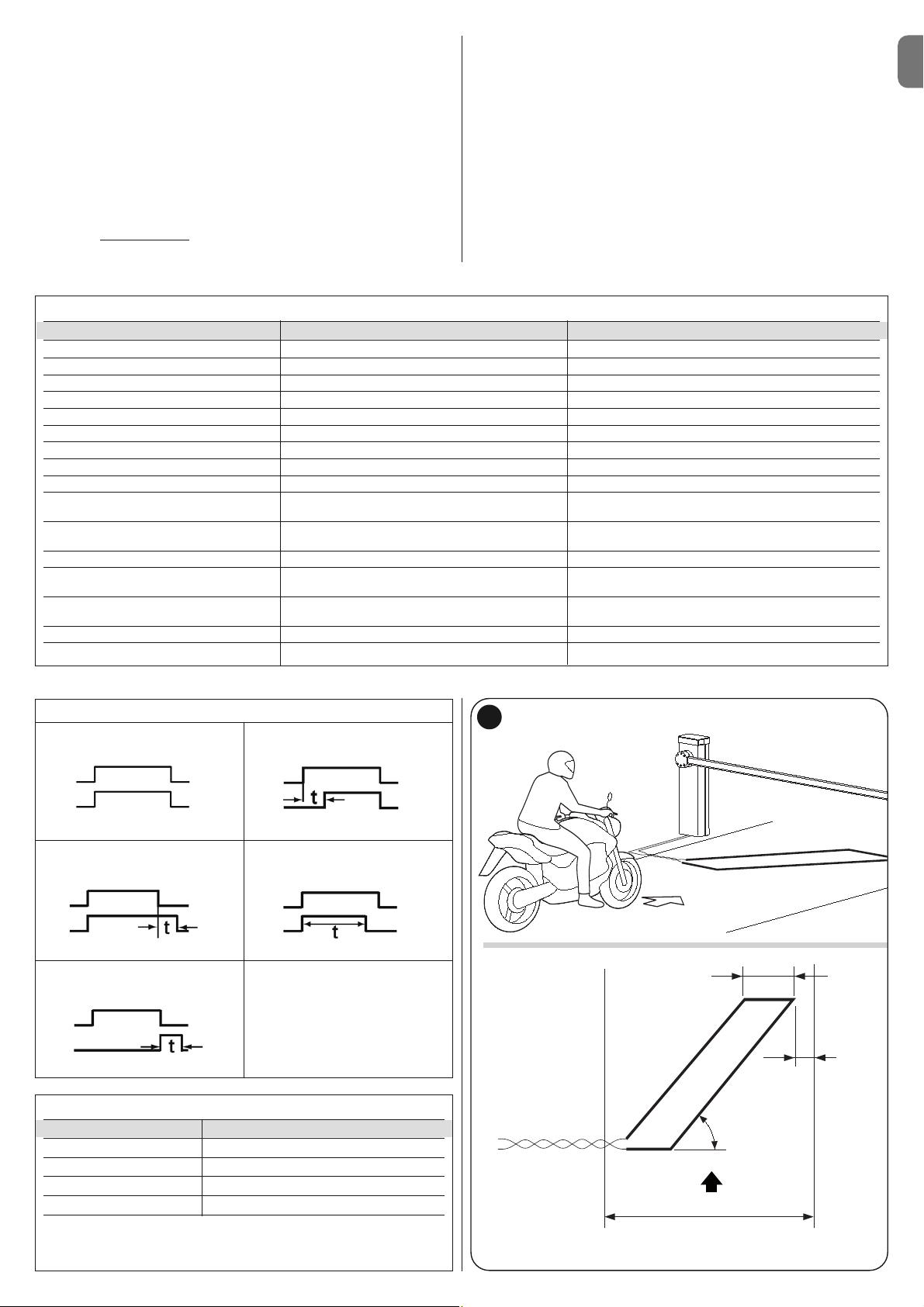
TABLE 17
Perimeter of the loop Number of turns to be carried out
2 – 4 m 6
4 – 7 m 5
7 – 12 m 4
more than 12 m 3
Note – If in the loop positioning place, below the floor, there are some metal
reinforcements, the inductivity of the loop is reduced. In this case, it is
necessary to add 2 turns to the twisting of the cable
EN
English – 17
able sheath. The length of the twisted cable must be less than 20 m.
01. After determining the size of the loop, dig a groove in the floor of a width =
8 mm and a depth = 30-50 mm (fig. H);
02. Clean the groove and insert the loop, trying to compact it in a way to avoid
it moving;
03. Carry out the number of turns of the loop depending on the perimeter, as
indicated in Table 17: use a 1.5 mm
2
unipolar isolated copper cable (fig. H);
04. Before sealing the groove, check that the value of the inductive loop is
between 100 and 400 uH or, through the Oview programmer, check that
the value of the measured frequency (Parameter “Loop Frequency”) is
between 30 and100 KHz;
05. Cover the loop with sand to protect it and then seal the groove with bitumen or resin for outdoor use (fig. H). Important! – The temperature of the
sealant must not exceed the maximum temperature admitted for the isolation of the cable, otherwise a loss in isolation towards the earth may occur.
TABLE 15
Function Values Default
Loop 1 sensitivity 10 – 100% 90%
Loop 2 sensitivity 10 – 100% 90%
Loop power supply on – off on
Loop 1 active on – off on
Loop 2 active on – off on
Loop 1 operating mode 1 – 5 1
Loop 2 operating mode 1 – 5 1
Loop 1 permanence time 2 – 20 = always 20 = always
Loop 2 permanence time 2 – 20 = always 20 = always
Output function 1, 2, 3:
Active out (1,2,3) for loop 1 selectable off
Output function 1, 2, 3:
Active out (1,2,3) for loop 2 selectable off
Calibration [also carried out upon start-up] on – off
Loop 1 activation mode*: 1 – 5 1
Loop 1 time 0 – 25 s 2s
Loop 2 activation mode*: 1 – 5 1
Loop 2 time 0 – 25 s 2s
Loop 1 frequency display 0 - 127000 Loop 2 frequency display 0 - 127000 -
G
approximately 0,8 m
Direction of travel
0,2 m
Route
45°
06. The electric cables must be connected to the Loop1 (fig. I) and Loop2
(fig. L) terminals. The Loop2 terminal presents 2 connection possibilities
(fig. L); based on the type of connection used, it varies the working fre-
quency of the loop.
Important! – If Loop1 is positioned near Loop2 and both work at the
same frequency (or almost), interference could be generated; in this case,
it is necessary to change the connection to Loop2 terminal.
TABLE 16
1
loop
relay
loop
relay
loop
relay
loop
relay
loop
relay
2
34
5
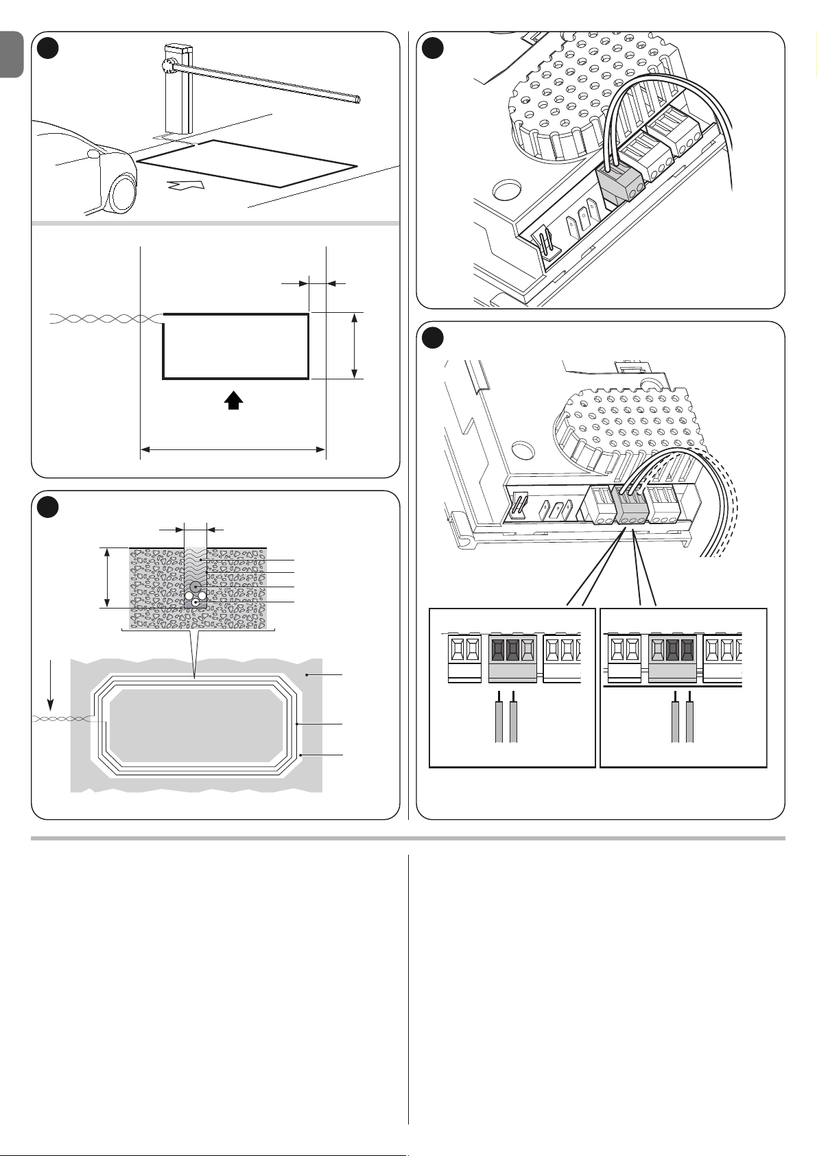
EN
18 – English
7.6 - Master - Slave mode
This operating mode is used if it is necessary to automate 2 counterposed barriers which perform synchronised movements. In this mode, a barrier works as
Master and commands the manoeuvres, while the second works as Slave and
carries out the commands sent from the Master barrier; by default all the barriers are set as Master.
To configure the barrier as Slave it is necessary to activate the level 1 function
“Slave Mode” (see Table 7).
The connection between Master and Slave takes place through the BusT4 with
the dedicated Master/Slave connector.
Important! – Should the Oview programmer be used, it is necessary to
modify the parameter “Together” or “Address” of one of the 2 barriers.
This is to avoid the simultaneous communication of the 2 control units
with the Oview programmer.
7.6.1 - Installation and electrical connections
Warnings
• All the devices, including the radio receiver, must be connected on the Master
barrier;
• If the buffer battery is used, each barrier must have its own;
• In the Slave barrier it is possible to carry out the following connections:
- its own flashing light (Flash)
- its own Pole Open Indicator (S.C.A.)
- pole lights
- its own sensitive edge (Stop)
- its own command device (P.P.), which commands the total opening of
the Slave pole only
- the Open and Close inputs are not used
- the Loop1 and Loop2 inputs programmed with “Open” mode
- the receiving radio
To install 2 barriers and program them with “Master - Slave” mode, proceed as
follows:
01. Install the 2 barriers (fig. M).
It is not important which of the two works as Master or Slave; it is necessary to assess the convenience to create the electrical connections and
that the “Step-Step” command that will carry out the Slave barrier will provide the total open of the Slave pole only;
02. Connect the two control units one to the other through the Master/Slave
connector (fig. 54), respecting the polarity indicated;
03. At this point, carry out the other electrical connections (fig. 54), referring to
the indications contained in chapter 4 - Electrical connections;
H
5 mm - 8 mm
Sealant
Groove
String
Loop
(the cable
must be inserted in the
groove)
Connection
(twisted cable)
Groove
5 - 8 mm
Earth
Twisted cable
I
L
F
approximately 0,35 m
Direction of travel
LOOP1 LOOP2 LOOP1 LOOP2
Route
1 m
30 mm -
50 mm

EN
English – 19
04. Once all the electrical connections are done, power each control unit and
for each one, follow the procedure described in paragraph 4.2 - Initial
start-up and electrical connections.
Important! – Should the Oview programmer be used, it is necessary to
modify the parameter “Together” or “Address” of one of the 2 control
units of the barrier; this is to avoid that the 2 control units communicate
with Oview at the same time.
05. In the Slave barrier, carry out the following programming:
a) Recognition of the connected devices (see paragraph 4.4)
b) Recognition of opening and closing positions (see paragraph 4.5)
c) Carry out any adjustments
d) Activate the “Slave Mode” parameter as described in paragraph 6.1 -
Level one programming (ON-OFF).
At this point, LED L7 starts flashing to signal a “Master-Slave communication error”. This is because the coupling of the Master barrier with the Slave
barrier has not yet been carried out.
Important! - In the counterposed barrier, before carrying out “the opening
and closing learning phase”, it is necessary to set the “Direction of
motor rotation” (parameter L8 - Table 7, paragraph 6.1);
Important – Consider that during operation, any programming on the Slave
barrier is ignored, since the programming on the Master barrier prevails,
excluding that reported in Table 18, which only affects the Slave barrier.
06. In the Master barrier, carry out the following programming:
a) Recognition of the connected devices (see paragraph 4.4)
b) Recognition of opening and closing positions (see paragraph 4.5)
c) carry out any adjustments;
07. Finally, from the Master control unit, send a command to carry out a
manoeuvre and check that the latter is also carried out by the Slave barrier.
TABLE 18
Level one functions (ON-OFF functions) Level two functions (adjustable parameters)
Stand-by Motor Speed
Start-up Flash Output
Slave Mode LED output
Long/short deceleration Motor force
Direction of motor rotation Braking
PRODUCT DISPOSAL
This product is an integral part of the automation system it controls
and must be disposed of along with it.
As in the case of installation, likewise at the end of product lifetime the disassembly and scrapping operations must be performed by qualified personnel.
This product is made of various types of material, some of which can be recycled while others must be scrapped. Seek information on the recycling and disposal methods envisaged by the local regulations in your area for this product
category.
Caution! – Some parts of the product may contain polluting or hazardous substances which, if released to the environment, may cause serious damage to
the environment or to human health.
As indicated by the symbol alongside, disposal of this product with domestic waste is strictly prohibited. Separate the
waste into categories for disposal, according to the methods
established by current legislation in your area, or return the
product to the retailer when purchasing a new version.
Caution! – Local legislation may impose heavy fines in the event of illegal disposal of this product.
• The manoeuvre is performed, but shortly afterwards the pole blocks
or performs a brief inversion: the selected force value may be too low to
enable the movement of the pole. Check the correct balancing of the pole; if
necessary set a higher force value. The sensitivity value could be too high:
lower the sensitivity value. If the activation takes place in the deceleration
phase, it is necessary to decrease the braking intensity.
• The manoeuvre is carried out at slow speed: the manoeuvre does not
start from one of the limit switches or the control unit does not recognise the
limit switch. Check the electrical connection of the limit switch.
• The Slave barrier does not perform the manoeuvres: check that the
“Master-Slave” learning phase has been carried out on both the barriers.
• The manoeuvre is carried out in the opposite way: check that the
parameter “Direction of motor rotation” (parameter L8 - Table 7, paragraph 6.1)
is set correctly, or invert the motor cables.
Possible causes of malfunctions are listed below, which may occur during the
installation phase, or in the case of faults, possible remedies:
• The radio transmitter does not control the barrier and the transmitter
LED does not illuminate: Check that the transmitter batteries are not dis-
charged and replace if necessary.
• The radio transmitter does not control the barrier but the transmitter
LED illuminates: check that the transmitter is correctly memorised on the
radio receiver. Ensure correct emission of the radio signal of the transmitter with
the following empirical test: Press a key and place the LED against the aerial of
a standard radio switched on and tuned to FM at the frequency of 108.5Mhz or
as close to this value as possible; a slight noise with a scratching pulse noise
should be heard.
• No manoeuvre is performed when a command is sent, and the OK
LED does not flash: check that the barrier is powered via the mains at 230 V.
Also check that the fuses F1 and F2 are not blown; in this case try to locate the
cause of the fault and then replace with a version with the same specifications;
see fig. 55.
• No manoeuvre is performed when a command is sent, and the flashing light remains off: check that the command is effectively received; if the
sent command reaches the SS input, the OK LED emits a double flash to indicate that the command is received.
• The manoeuvre does not start and the courtesy light flashes a few ti mes: count the number of flashes and check against the data in Table 19.
WHAT TO DO IF…
(troubleshooting guide)
8
TABLE 19
Diagnostics with programming led
L1 fast flash: device memory error
L2 fast flash: position memory error
L3 fast flash: parameter memory error
L4 fast flash: flashing short circuit or courtesy light
L5 fast flash: encoder counting error
L6 fast flash: inverted limit switch error or limit switch not freed by the
set time
L7 fast flash: Master/Slave communication error
L8 fast flash: version error
M
Note – Should you decide to use the “total standby” function in the barriers with the Master-Slave configuration, it is necessary to carry out the electrical connec-
tion using the BusT4 connector and not the Master-Slave connector.

EN
20 – English
TECHNICAL CHARACTERISTICS OF THE PRODUCT
WARNINGS: • All technical specifications stated in this section refer to an ambient temperature of 20°C (± 5°C). • Nice S.p.a. reserves the right to apply modifi-
cations to products at any time when deemed necessary, maintaining the same intended use and functionality.
Model M3BAR M5BAR M7BAR LBAR
Product Type Road barrier for residential use complete with electronic control unit
Useful conduit (m) 2,32 ÷ 2,82 3,17 ÷ 4,82 5 ÷ 7 7 ÷ 9
Maximum torque on start-up (Nm) 100 200 300 400
Nominal torque (Nm) 30 70 90 130
Manoeuvre time (sec adjustable) 1.5 – 4 3 – 6 6 – 10 8 – 12
Maximum operating cycle 500 350 200 150
frequency at nominal torque continuous use continuous use
(the control unit limits the work
cycles to the maximum set in table T3)
Durability See chapter 3 - paragraph 3.2.1
Power supply voltage 230 Vac 50/60Hz 230 Vac 50/60Hz 230 Vac 50/60Hz 230 Vac 50/60Hz
Power supply voltage /V1 120Vac 50/60Hz 120Vac 50/60Hz 120Vac 50/60Hz 120Vac 50/60Hz
Maximum power absorbed 150 110 110 160
on start-up (W)
Maximum power at nominal 40 50 40 50
torque (W)
Insulation class 1111
Emergency power supply Yes (with PS224 accessory)
Photovoltaic power supply Yes (with SYKCE accessory)
FLASH output for 1 LUCYB, MLB or MLBT flashing light signal (12V – 21W)
LIGHT output for optional accessory XBA4 “pole lights”
SCA output for signal indicator 24V (max 10W)
Output for flashing light/ with optional accessories XBA7 LED flashing light or XBA8 LED traffic light
traffic light on cover
BLUEBUS output 1 output with maximum load of 12 Bluebus units
“STOP” input For normally closed, normally open, 8.2 kΩ constant resistance or OSE optical type contacts;
in self-learning mode (a change from the memorised state prompts the “STOP” command)
“STEP-STEP” input For Normally Open contacts
“OPEN” input For Normally Open contacts
“CLOSE” input For Normally Open contacts
Radio connector SM connector for receiver types SMXI, SMXIS, OXI or OXIT
Radio AERIAL input 50 Ω for RG58 or similar type cable
Loop Detector Inputs 2 per loop with a circumference from 2 to 16 m
Nominal Loop inductance 100 to 400 uH
Programmable functions 8 ON-OFF functions and 8 adjustable functions (see tables 6 and 8) and additional programming
through the Programming Unit and Oview Command
Functions in self-learning mode Self-learning of devices connected to the BlueBus output. Self-learning of “STOP” type devices (contacts NO, NC
or 8.2kΩ resistance). Learning of pole opening and closing positions and calculation of the points of deceleration
and partial opening. Self-learning of the “Version”
Operating temperature -20°C ÷ +50°C -20°C ÷ +50°C -20°C ÷ +50°C -20°C ÷ +50°C
Use in particularly acid, No No No No
saline or potentially
explosive atmospheres
Protection rating IP44 IP44 IP44 IP44
Dimensions (mm) 400 x 299 x 1215 h 400 x 299 x 1215 h 400 x 299 x 1215 h 500 x 299 x 1215 h
Weight 80 kg 80 kg 85 kg 98 kg

EN
English – 21
APPENDIX I
To be used only in the case of installations in conformity with chapter 1 and more specifically paragraph 1.3.1
To be detached, compile box N°1 and deliver to automation owner together with the operation manual and maintenance schedule
CE declaration of conformity
Declaration in accordance with Directives: 2004/108/CE (EMC); 1999/5/CE (R&TTE), 2006/42/CE (MD) Appendix II, part A;
89/106/CEE (CPD) procedure according to appendix III, ii, possibility 2 (System 3)
Note - The content of this declaration corresponds to the declaration made in the official document filed in the offices of Nice S.p.a., and particularly the latest version thereof available prior to the printing of this manual. The text contained here has been adapted to meet editorial requirements. A copy of the original declaration may be requested from Nice S.p.a. (TV) I.
Declaration number: 404/M-LBAR Revision: 0 Language: EN
Name of manufacturer: NICE S.p.A.
Address: Via Pezza Alta 13, Rustignè Industrial Zone, 31046 Oderzo (TV) Italy
Person authorized to
provide technical
documentation: Mr. Oscar Marchetto
Product type: Electromechanical barrier lift
Model / Type : M3BAR, M5BAR, M7BAR, LBAR
Accessories: XBA14, XBA15, XBA4, XBA6, XBA18, XBA9, XBA7, XBA8
The undersigned Luigi Paro, as Managing Director, hereby declares under his own responsibility that the product identified above complies with the provisions
of the following directives:
• DIRECTIVE 2004/108/EC OF THE EUROPEAN PARLIAMENT AND COUNCIL of December 15 2004 concerning alignment of Member States’ legislation
regarding electromagnetic compatibility and abrogating directive 89/336/EEC, according to the following harmonized standards: EN 61000-6-2:2005, EN
61000-6-3:2007
• Directive 2006/42/EC OF THE EUROPEAN PARLIAMENT AND COUNCIL of May 17 2006 regarding machines and amending directive 95/16/EC (consolidated text)
Should the machinery be put into service in a European country with an official language different from the one of this declaration, the importer must attach
the translation of this document to the declaration.
• Directive 89/106/EEC of the European Council of 21 December 1988 regarding the approximation of legislation, regulations and administration of Member
States concerning construction products, according to the following harmonised standards: EN 13241-1:2003
Also conforms to the essential requirements specified in article 3 of the following community directive, for the products’ intended use:
• Directive 1999/5/CE OF THE EUROPEAN PARLIAMENT AND COUNCIL dated March 9 1999 regarding radios and communications terminals and reciprocal recognition of their conformity in accordance with the following harmonized standards:
• Protection of health (art. 3(1)(a)): EN50371:2002
• Electrical safety (art. 3(1)(a)): EN60950-1:2006+A11:2009
• Electromagnetic compatibility (art. 3(1)(b)): EN301489-1V1.8.1:2008, EN301489-3V1.4.1:2002
• Radio spectrum (art. 3(2)): EN 300 330-2 V1.5.1:2010
In accordance with directive 1999/5/CE (annex V), the product is classified as class 1 and marked:
The product also complies with the following standards:
EN 60335-1:2002 + A1:2004 + A11:2004 + A12:2006 + A2:2006 + A13:2008+A14:2010
The parts of the product which are subject to the following standards comply with them:
EN 13241-1:2003, EN 12445:2002, EN 12453:2002, EN 12978:2003, EN 60335-2-103:2003+A11:2009
Oderzo, June 21 2011
Luigi Paro
(Managing Director)
Essential requirements for CE marking
Characteristics Certifying Authority Document
Release of hazardous substances CERT(CPD n°1600) 374/11, 375/11, 376/11, 377/11
Resistance to wind load CERT(CPD n°1600) 374/11, 375/11, 376/11, 377/11
Safe opening for vertically moving doors CERT(CPD n°1600) 374/11, 375/11, 376/11, 377/11
Mechanical strength and stability – 2009_002 SP S14
Manoeuvring forces for power-operated doors/gates CERT(CPD n°1600) 374/11, 375/11, 376/11, 377/11
(*) CERT of Treviso Tecnologia in Lancenigo di Villorba (Tv)
0682
Box N° 1
The installation of the product: M-LBAR Road Barrier matricola N° serial N° (see label):.....................................................................................................
Complete with pole: XBA4 and following accessories: ..........................................................................................................................................................
Was performed by:
Company: ................................................................................................. Address: ........................................................................................................
Name and Surname of responsible installer: ........................................................................................................................................................................
The installer hereby declares to have strictly observed all provisions of the instruction manual enclosed with the product:
Data ....................................................... Signature: ........................................................................
Place of product installation, at: .................................................................. Address: ........................................................................................................
Caution! – This declaration of conformity is not to be considered valid if all fields in this box are not duly compiled.

EN
22 – English
APPENDIX II
Declaration of conformity to be used in case the product is not installed in compliance with the criteria reported in chapter 1.3.1.
CE declaration of conformity
and declaration of incorporation for a “quasi-machine”
Declaration in accordance with Directives: 1995/5/EC (R&TTE), 2004/108/EC (EMC);
2006/42/EC (MD) annex II, part B
Note - The content of this declaration corresponds to the declaration made in the official document filed in the offices of Nice S.p.a., and
particularly the latest version thereof available prior to the printing of this manual. The text contained here has been adapted to meet editorial requirements. A copy of the original declaration may be requested from Nice S.p.a. (TV) I.
Declaration number: 402/M-LBAR Revision: 0 Language: EN
Name of manufacturer: NICE S.p.A.
Address: Via Pezza Alta 13, Rustignè Industrial Zone, 31046 Oderzo (TV) Italy
Person authorized to
provide technical
documentation: Mr. Oscar Marchetto
Product type: Electromechanical barrier lift
Model / Type : M3BAR, M5BAR, M7BAR, LBAR
Accessories: XBA14, XBA15, XBA4, XBA6, XBA18, XBA9, XBA7, XBA8
The undersigned Luigi Paro, as Managing Director, hereby declares under his own responsibility that the products identified
above comply with the provisions of the following directives:
• Directive 1999/5/CE OF THE EUROPEAN PARLIAMENT AND COUNCIL dated March 9 1999 regarding radios and communications terminals and reciprocal recognition of their conformity in accordance with the following harmonized standards:
- Protection of health (art. 3(1)(a)): EN50371:2002
- Electrical safety (art. 3(1)(a)): EN60950-1:2006+A11:2009
- Electromagnetic compatibility (art. 3(1)(b)): EN301489-1V1.8.1:2008, EN301489-3V1.4.1:2002
- Radio spectrum (art. 3(2)): )): EN 300 330-2 V1.5.1:2010
In accordance with directive 1999/5/CE (annex V), the product is classified as class 1 and marked:
• DIRECTIVE 2004/108/EC OF THE EUROPEAN PARLIAMENT AND COUNCIL of December 15 2004 concerning alignment of Member States’ legislation regarding electromagnetic compatibility and abrogating directive 89/336/EEC, according to the following harmonized standards: EN 61000-6-2:2005, EN 61000-6-3:2007
The product also complies with the following directive in accordance with the requirements for “quasi-machines” :
• Directive 2006/42/EC OF THE EUROPEAN PARLIAMENT AND COUNCIL of May 17 2006 regarding machines and
amending directive 95/16/EC (consolidated text)
- I declare that the pertinent technical documentation has been prepared in accordance with Annex VII B to Directive
2006/42/EC and that the following essential requirements have been met: 1.1.1- 1.1.2- 1.1.3- 1.2.1-1.2.6- 1.5.1-1.5.2-
1.5.5- 1.5.6- 1.5.7- 1.5.8- 1.5.10- 1.5.11
- The manufacturer agrees to send the national authorities pertinent information on the “quasi-machine” in response to a
motivated request without affecting its intellectual property rights.
- If the “quasi-machine” is operated in a European country with an official language other than the language used in this
declaration, the importer must associate a translation with this declaration.
- The “quasi-machine” must not be operated until the final machine in which it is to be incorporated is declared to conform
to the provisions of Directive 2006/42/EC, if applicable to it.
The product also complies with the following standards:
EN 60335-1:2002 + A1:2004 + A11:2004 + A12:2006 + A2:2006 + A13:2008+A14:2010
The parts of the product which are subject to the following standards comply with them:
EN 13241-1:2003, EN 12445:2002, EN 12453:2002, EN 12978:2003, EN 60335-2-103:2003+A11:2009
Oderzo, June 21 2011
Luigi Paro
(Managing Director)
0682

EN
English – A
IMPORTANT! – The gearmotor release and locking operations
must be performed only when the pole is horizontal and stationary.
To manually lock and release the barrier, insert the key supplied and
turn it by 180° (fig. A); the key can be turned to the left or to the right.
Operation manual
(to be given to the final user of MBAR and LBAR)
Warnings
1 - Children: An automation system guarantees a high level of safety,
using its detection systems to prevent movement in the presence of
persons or objects, and ensuring constantly foreseeable and safe activation. Nonetheless, it is advisable to ensure that children do not play
in the vicinity of the automation. This is not a toy!
2 - This product is not designed to be used by persons (including children) whose physical, sensorial or mental capacities are reduced, or
with lack of experience or skill, unless suitable instructions regarding
use of the product have been provided by a person responsible for
safety or under supervision of the latter.
3 - Malfunctions: if the automation is seen to perform abnormally,
disconnect the electrical power supply from the system and manually
release the gearmotor. Never attempt to perform repairs; contact your
local installer for assistance. In the meantime the system can be used
as a manual access point, after releasing the gearmotor as described
be low in this document. In the event of breakage or a power fail-
ure, while waiting for the installer or the electrical power supply to
return, if the buffer battery is not fitted, the automation can still be
used. Manually release the gearmotor (see step 9 - Gearmotor manual releasing and locking) and move the pole manually as required.
4 - Safety devices disabled: the barrier can be operated even when
the safety device on the barrier does not work correctly:
- Activate the barrier command (with the transmitter or key-operated
selector switch, etc.); if all is in working order, the pole opens or
closes normally; otherwise the flashing light emits a number of flashes and the manoeuvre is not started (the number of flashes depends
on the reason for which the manoeuvre does not start).
- In this case, the user must press and hold the command within three
seconds.
- After approx. 2 seconds the barrier will start to operate in “hold-torun” mode, i.e. the pole will continue to move while the command is
activated; THE POLE STOPS AS SOON AS THE COMMAND IS
RELEASED.
If the safety devices are out of service, the automation must be
repaired as soon as possible.
5 - Even if you possess the skills, never modify the system or pro-
gramming and setting parameters of the automation: this is the
responsibility of the installer.
6 - Testing, periodic maintenance and any repairs must be documented by the person performing the operations and the relevant documents must be kept by the system owner. The only operations that
can be performed by the user periodically are to clean the photocell
lenses and the automation. To prevent anyone from activating the barrier, release the automation system before proceeding with the operations (as described below). Use a slightly damp cloth to clean.
7 - Disposal: At the end of the automation’s lifetime, ensure that it is
disposed by qualified personnel and that the materials are recycled or
scrapped according to current local standards.
8 - Gearmotor manual release and locking: The gearmotor is
equipped with a mechanical system that enables manual opening and
closing of the pole. These operations are required in the event of a
power failure or malfunctions.
Before using the automation for the first time, ask the installer to explain the origin of residual risks and devote a few minutes to reading this user
instruction and warning manual given to you by the installer. Keep the manual for reference when in doubt and pass it on to new owners of the
automation.
IMPORTANT! – Your automation is a machine that performs your commands faithfully; negligent or improper use may constitute
a hazard:
– Never activate automation controls if persons, animals or objects are present in the operating range.
– Never touch parts of the automation while the pole is moving!
– Transit is only permitted if the pole is completely open and stationary!
A
a


EN
English – B
Maintenance schedule
(to be given to the final user of MBAR and LBAR)
MAINTENANCE SCHEDULE
Important! – System maintenance must be performed by tech-
nical and qualified personnel, in strict observance of safety
standards as envisaged by current legislation and the safety
precautions stated in Chapter 1 - “General safety warnings and
precautions”, at the start of this manual.
In general, the road barrier does not require special maintenance;
however, regular checks over time will guarantee system efficiency and
ensure correct operation of the safety systems installed.
If the road barrier is equipped with other devices not mentioned in this
manual, follow the instructions in the relative maintenance schedules.
Considering normal domestic use of the automation, periodic checks
of the system are recommended: every 6 months or 50,000 maneouvres.
Note also that in the event of spring breakage, the road barrier still
remains compliant with the requirement in 4.3.4 of the standard EN
12604: 2000.
• The pole balancing system must be checked at least twice a year,
preferably when the season changes.
At the envisaged interval, the following checks and replacements must
be made for maintenance.
1 Disconnect any electrical power source.
2 Check the state of deterioration of all the materials of the barrier,
paying special attention to cases of corrosion or oxidation of the
structural parts; replace the parts that do not provide sufficient
guarantee.
3 Check that the screw connections are adequately tightened (espe-
cially those of the balancing screw)
4 Check the absence of clearance between the balancing lever and
the output shaft. If this is the case, tighten the central screw down.
5 Lubricate the rod end of the balancing screw and the lower bolt.
6 In the M7BAR and LBAR versions, check the perfect locking
between the two pole segments. Use the expansion screws if necessary.
7 Position the pole in the vertical position and make sure that the
pitch between the loops of the balancing screw is constant without
deformations.
8 Release and check the correct balancing of the pole and any
obstacle during manual opening and closing.
9 Release again and carry out the test procedure.
10 Check protection against the risk of lifting: on automations
with vertical movement, it must be ensured that there is no risk of
lifting. This test can be performed as follows: hang a weight of 20
kg mid-way along the pole (for example, a sack of gravel), activate
an Opening manoeuvre and ensure that during operation the pole
does not exceed the height of 50 cm from the closing position. If
the pole exceeds this height, reduce the motor force (see chapter 6
- Table 7).
MAINTENANCE REGISTER
Important – This register must be given to the automation owner after compilation of all required parts.
This register must list all maintenance operations, repairs and modifications performed. The Register must be updated on each operation and
stored in a safe place for future inspections by authorised organisations.
This Maintenance Register refers to the following automation:
mod. MBAR and LBAR - serial n° ......................... - date of installation ......................... - at ...............................................................................
The following enclosed documents are part of the Register:
1) - Maintenance schedule
2) - ............................................................................................
3) - ............................................................................................
4) - ............................................................................................
5) - ............................................................................................
6) - ............................................................................................
According to the enclosed document “Maintenance Schedule”, maintenance operations must be performed at the following intervals:
every 6 months or 50,000 manoeuvre cycles, depending on which event occurs first.
11 If hazardous situations generated by the moving poles are protect-
ed by means of impact force limitation, measure the force as specified in the standard EN 12445. If motor force control is used as
auxiliary function with the system for reduction of impact force, test
and identify the setting that obtains the best results.
12 Check efficiency of the release system: place the pole in the
Closing position and manually release the gearmotor (see paragraph 3.6) ensuring that there is no difficulty with this procedure.
Ensure that the manual force required to move the pole on opening
is no greater than 200 N (approx. 20 Kg); the force is measured
perpendicular to the pole and at 1 m from the rotation axis. Lastly,
ensure that the key required for manual release is available in the
vicinity of the automation.
13 Power supply disconnection system check: by using the pow-
er disconnect device, and disconnecting any buffer batteries, en sure that all leds on the control unit are off and that the rod re mains
stationary when any commands are sent. Check efficiency of the
locking device to prevent inadvertent and/or unauthorised connection.

EN
C – English
Date
Description of operation
(describe checks, adjustments, repairs, modifications etc.)
Signature of
technician
Signature of
owner
❑ That all phases as envisaged in the maintenance schedule have been performed.

I
2
1
B
A
C
B
298,5 mm
464,5 mm
400 mm
1219,5 mm
900 mm
M3BAR / M5BAR / M7BAR
L-Bar
298,5 mm
464,5 mm
500 mm
1219,5 mm
900 mm
• EN - with joint • IT - con giunto • FR - avec raccord • ES - con unión
• DE - mit Gelenkverbindung) • PL - ze złączką) • NL - met verbindingsstuk

II
4
3
b
a
c
d
g
h
f
e
c
a
b

III
5
6
MBAR
a
c
d
b

IV
90°
8
9
MBAR
a
b
c
a
b
7
a
b

V
180°
10
11
LBAR
c
aa
b
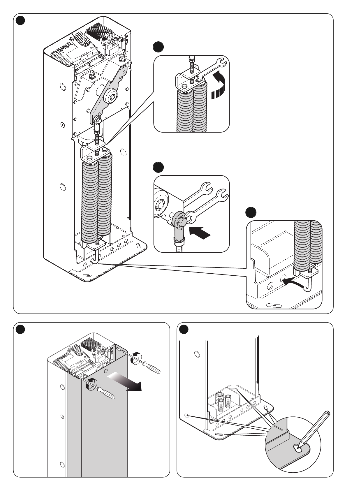
VI
13 14
12
LBAR
c
a
b

VII
15
16
1817

VIII
19
20
21
23
22

IX
24
26
25
28
1 cm
27
29

X
33
34
30
31
32
c
a
b
c
a
b

XI
35 36
37
45°
38
a
b
a
b
c

LN
4039
NC
NCNO NOCC
MOTB/MOFB
OPEN CLOSE
TX RX
24V 4W
LIGHTFLASHSCA BLUEBUS STOP OPEN CLOSEP.P.
LIGHTFLASHSCA BLUEBUS STOP OPEN CLOSEP. P.
LOOP2LOOP1
41
IN 1
IN 2
IN 3
LOOP 2
MASTER
SLAVE
LOOP 1
OUT 3
OUT 2
OUT 1
c
a
b

XIII
42 43
44
STOP
45
46
LIGHT
47

XIV
48
49
50
a
b
c

XV
51
52
a
b

XVI
53
a
b
c
d
e
f
g

XVII
LIGHTFLASHSCA
MOTB
OPEN CLOSE
TX RX
BLUEBUS STOP OPEN CLOSEP.P.
24V 4W
BUS T4 M/S
LOOP2LOOP1
LIGHTFLASHSCA BLUEBUS STOP OPEN CLOSEP.P.
24V 4W
BUS T4 M/S
LOOP2LOOP1
NC
NCNO NOCCNCNCNO NOCC
54
MASTER
SLAVE

XVIII
F1F1
F2F2
55


ISTML-BARR01.4865_07-10-2011
www.niceforyou.com
Nice SpA
Oderzo TV Italia
info@niceforyou.com
 Loading...