

Page 1
EN - Installation instructions
IT - Istruzioni per l’installazione
FR - Instructions pour l’installation
ES - Instrucciones para la instalación
DE - Anleitungen für die Installation
PL - Instrukcje montaż
NL - instructies voor de installatie
Nice
HSDOM21
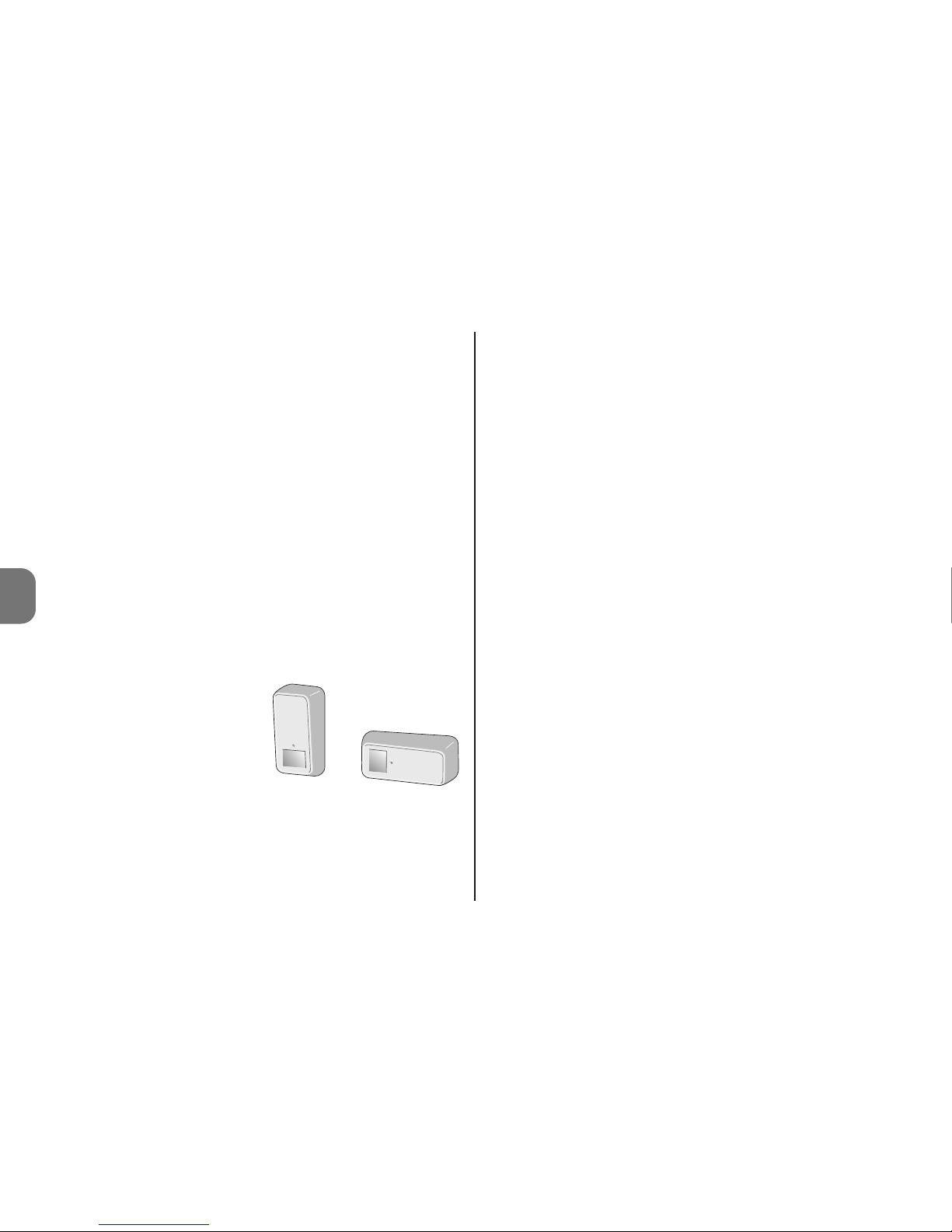
Home security outdoor detector
0682
Page 2

Page 3

EN
English - 1
Original instructions
ENGLISH
SPECIAL WARNINGS
• Install the product in a position that is difficult to reach.
• Never install the product close to possible turbulence of hot
or cold air or where there are hot-blooded animals (fig 1).
• If the area to be protected is subject to the presence of
domestic animals, the HSDOM21 should be positioned at
an adequate height and directed correctly to maintain the
sensitivity area at 50-70 cm from the ground, as shown in
fig 2 (vertical view); the sensor sensitivity value may also be
reduced if required.
• Never install HSDOM21 in locations subject to direct sunlight, to avoid internal overheating; the sun does not cause
damage to the product but may vary the sensitivity of the
infrared detector, thus impairing the effects of compensation of the ambient temperature, which is different from the
internal product temperature.
• Never use HSDOM21 to protect external areas subject to
adverse weather conditions, such as snow or heavy rain,
as these may cause false alarms.
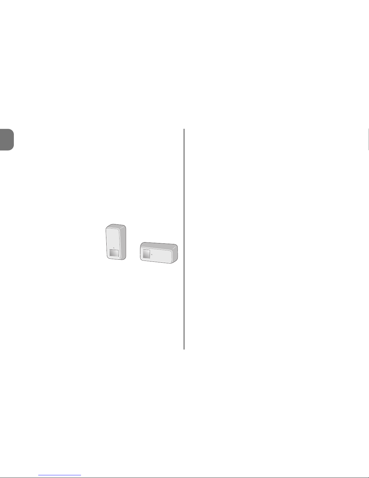
HSDOM21 is a volumetric detector with dual technology,
infrared and microwave radar. It is designed to cover an area
of up to 12 m with an angular opening of 90°; it is fitted with
sensitivity adjustment, alarm type selection (immediate or on
second pulse) and protection against opening and removal.
It is suitable for use in external protected environments
. Any
other use is to be considered improper and is strictly
prohibited! Nice declines all liability for damage resulting
from improper use of the product and other than as
specified in this manual.
1 - OPERATION
HSDOM21 is a volumetric detector with dual technology (PIR
= Passive Infra-Red detector + MW = Micro Wave Doppler
detector) designed to detect movements within a protected
area. The two different technologies reduce the possibility of
improper alarms due to environmental factors; for optimal
operation the product must be positioned and set correctly.
In the most extreme cases, to further reduce the risk of
improper alarms, two detectors may be installed in the same
area, in opposed mode and setting the control unit with the
“AND” function (see control unit instruction manual). Use of
the directional joint mod. HSA3 (optional accessory) enables
correct positioning and orientation of the product, in particular for fixing in corners (see chap. 2 - Installation).
HSDOM21 operates with 3 AA type alkaline batteries; it does
not have any electrical connection to the exterior and in the
event of intrusion detection, it transmits an alarm via radio to
the control unit.
In the product, the infrared detector is always active and in
the event of intrusion detection (green led LIT), it immediately activates the microwave detector (orange led lit); if this also
confirms the presence of a moving body, the alarm status is
generated (red led lit).
Caution! – When the upper cover of HSDOM21 is removed,
the system remains active.
The detector is fitted with protections against removal and
opening.
Page 4
2 - English
EN
HSDOM21 transmits signal to the control unit around every
40 minutes to indicate that the system is running; this is necessary for the “supervision function” on the control unit.
2 - INSTALLATION
Warnings
• Locate the position and height for fixing HSDOM21, ac cording to the protection area required: refer to fig. 2.
• Carefully check the form of the area to be protected; if in
doubt, before making the final fixture, temporarily secure
the product and perform some tests and make adjustments as required.
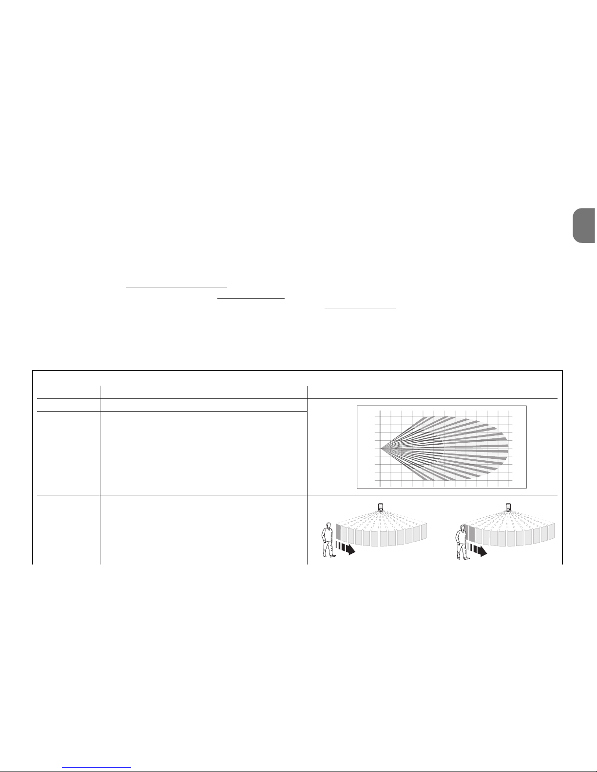
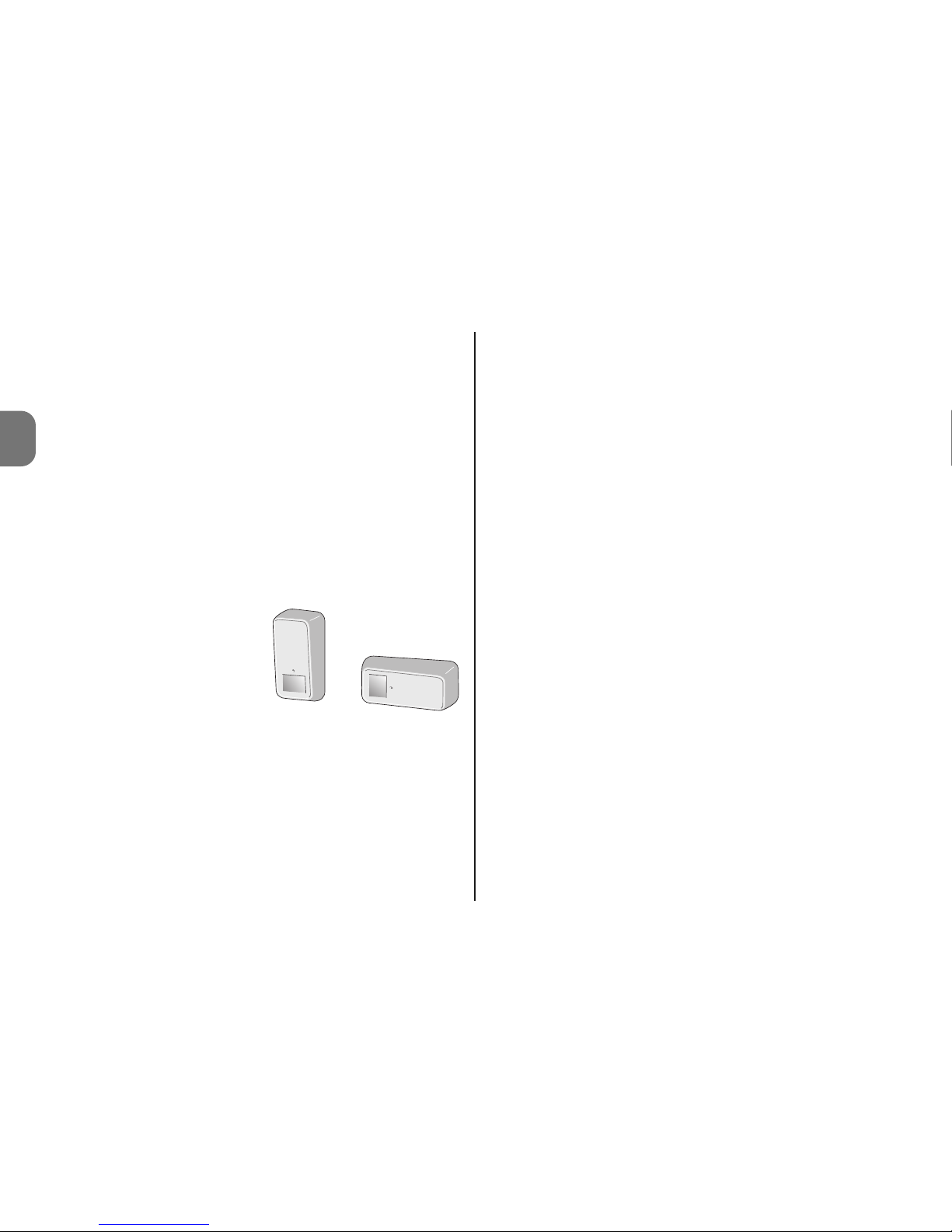
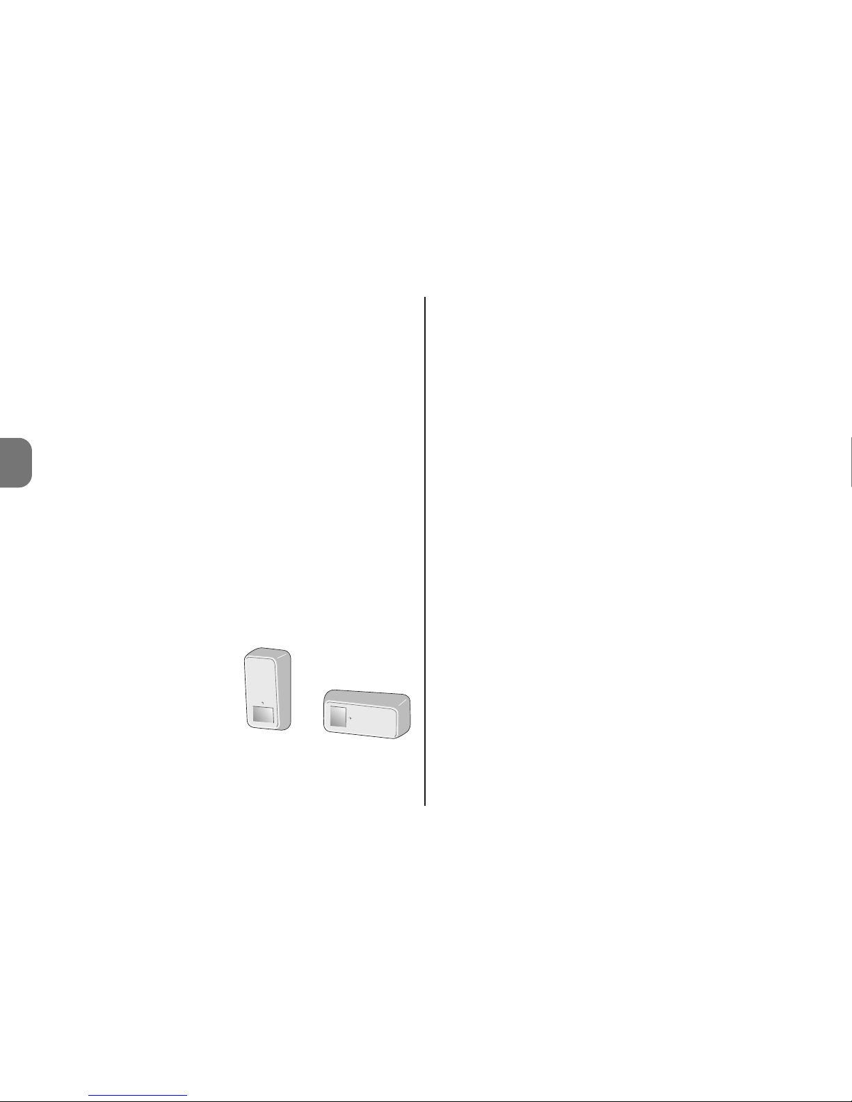
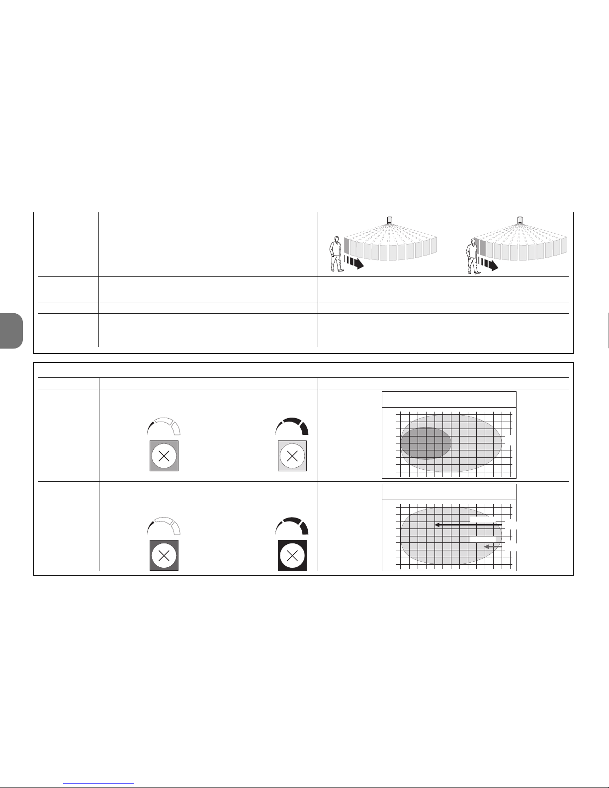
• The special design of the infrared sensor lens creates a
sensitive “curtain” area. If
the detector is positioned
vertically, the sensitive area
is horizontal (parallel to the
ground); if the detector is
positioned horizontally, the
sensitive area is vertical
(curtain protection with barrier effect).
It is important to carefully evaluate these factors ac cording
to the area to be protected, in relation to possible insensitivity to animals and considering the risk of rapid transit
through the area.
• If the product is to be installed in a corner, the directional
joint model HSA3 should be used (optional accessory):
Caution! – Use of the joint partly reduces efficiency of the
anti-removal protection, as the magnet remains on the
bracket. If the magnet is not used, the protection must be
inhibited by setting dip-switch 5 to ON.
01. Select the bracket fixture position, ensuring that it is
compatible with the overall dimensions of the detector: it
must be possible to access the release lever (fig. 3) with
sufficient clearances to connect and disconnect the
detector.
02. A – Wall-mounting: drill two holes for insertion of the
wall plugs and a hole for the magnet, used for the antiremoval protection. Then secure the bracket by means
of the plugs (fig. 4-A);
02. B – Corner-mounting with directional joint mod.
HSA3: fix the joint to the wall (see relative instruction
manual), then secure the bracket to the joint as shown in
fig. 4-B;
03. Open the housing by loosening the 4 rear screws (fig. 5);
04. Set the control unit to learn HSDOM21 (see control unit
instruction manual);
05. Open the battery compartment as shown in fig. 6 and
remove the insulation tab keeping the batteries disconnected: HSDOM21 emits two series of 3 beeps and
starts programming in self-learning mode; this is confirmed by 1 beep emitted by the control unit (4 beeps
indicate that the device is already programmed).
06. Program the dip switches (fig. 7) and set the trimmers
(fig. 7) with reference to chapter 3 - Programming; then
perform the operation “Test” , see paragraph 3.1.
07. Close the housing (fig. 8) and connect the HSDOM21 to
the fixing bracket (fig. 9).
3 - PROGRAMMING
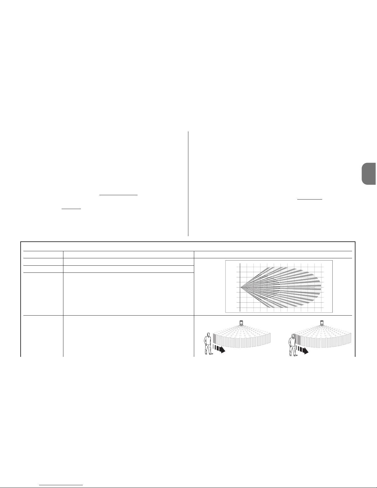
HSDOM21 is equipped with 5 dip-switches (fig. 7) which
enable programming of a number of operating parameters
vertical
horizontal
Page 5
EN
and 2 adjustment trimmers (PT1 and PT2 - fig. 7): see
Table 1 and Table 2.
3.1 - Programming procedure and Operation Test
01. First program the infrared detector with 1 alarm pulse:
dip-switch 3 = OFF (Table 1).
02. Then program the PIR infrared detector sensitivity: dipswitch 2 with the minimum required value
(Table 1).
03. Set the “delay after intrusion” to the minimum value
:
trimmer PT2 (fig. 7).
04. Set the microwave detector sensitivity value (trimmer
PT1 - fig. 7).
05. Check coverage of the protected area: make a number
of brief movements within the area and check the signals
emitted by the led. If necessary, adjust the sensitivity value. Caution! – The infrared sensor lens is fixed on the
cover and therefore the detection tests must be performed with the device closed.
06. After adjusting sensitivity, to reduce the risk of improper
alarms, set dip-switch 3 to ON (2 pulses for alarm).
07. For the same reason, set the “delay after intrusion” to the
maximum value
. trimmer PT2 (fig. 7), according to
detection requirements.
08. After testing operation, set dip-switch 4 to ON to switch
off the led signals.
Table 1
Dip Switch Function Notes
Dip 1 Not used
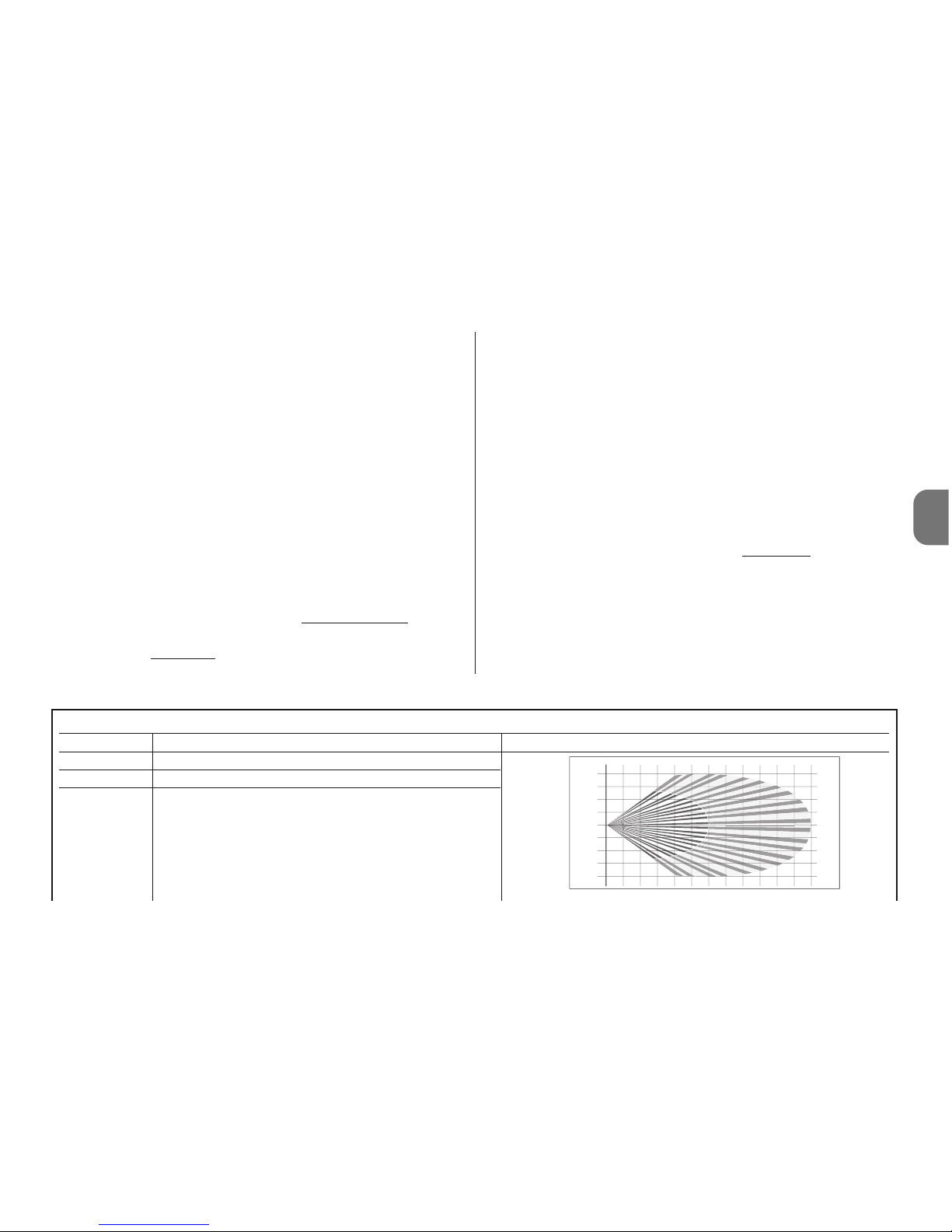
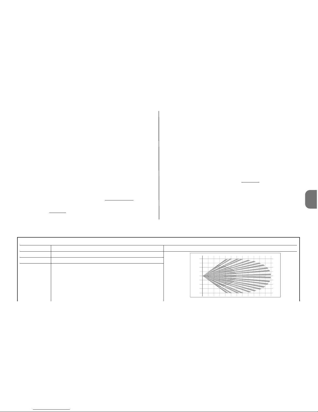
Dip 2 = OFF Infrared sensor sensitive area up to 6 m
Dip 2 = ON Infrared sensor sensitive area up to 12 m
Dip 3 = OFF N° infrared pulses for alarm = 1
Dip 3 = ON N° infrared pulses for alarm = 2
123456789101112
0
1
2
3
4
4
3
2
1
m
m
English - 3
Page 6
4 - English
EN
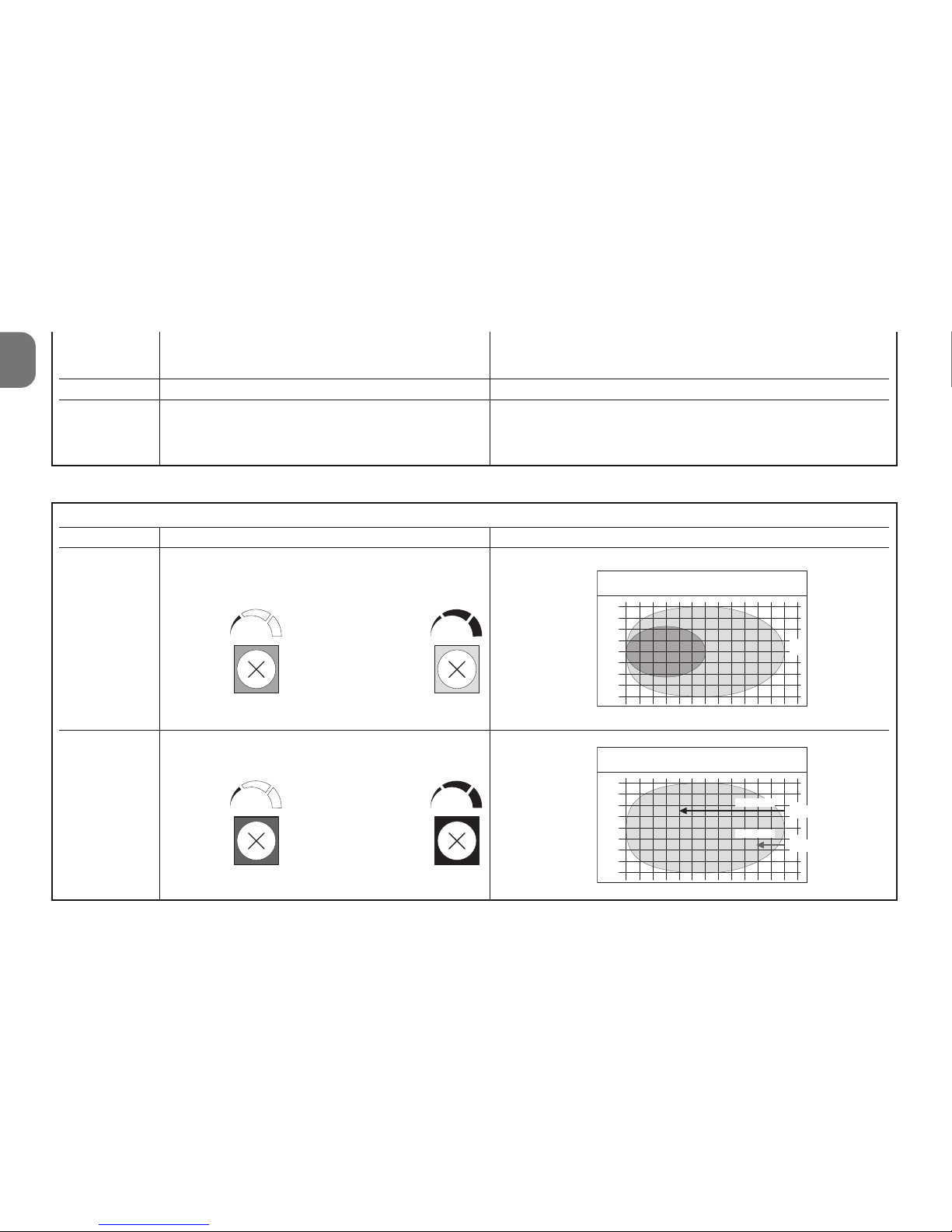
Table 2
Trimmer Function Notes
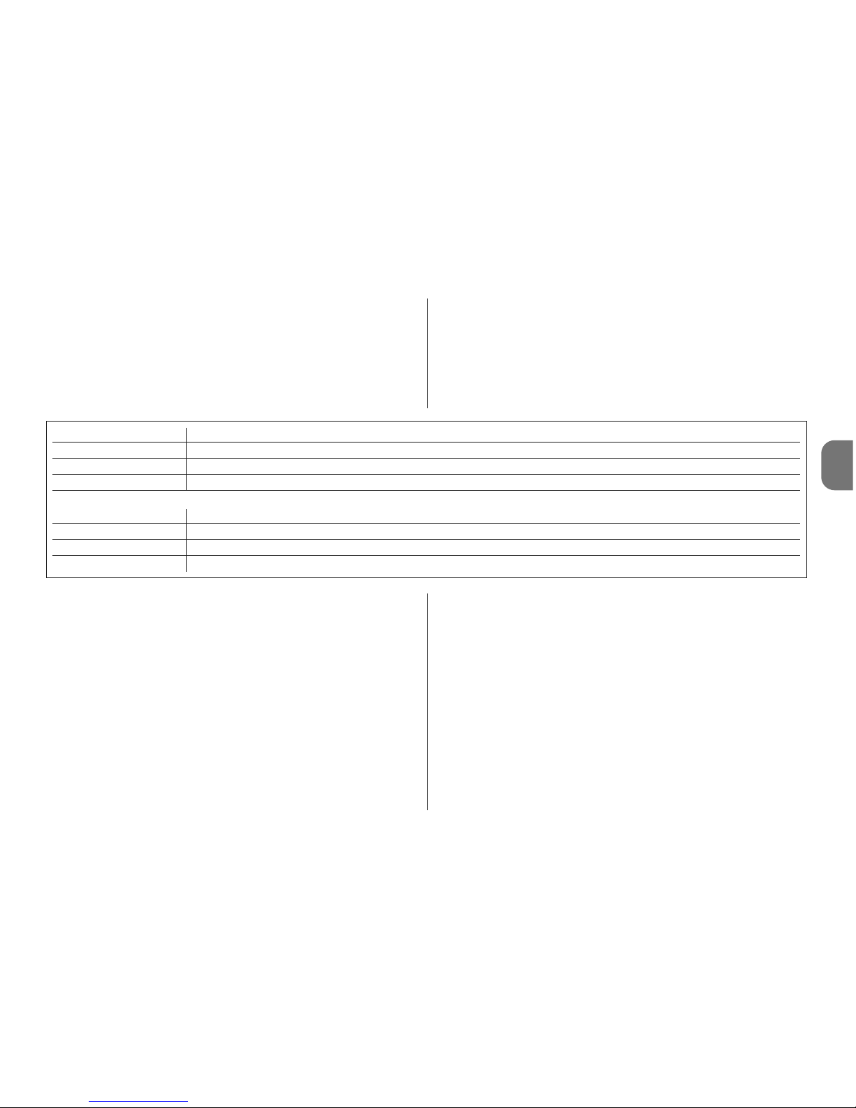
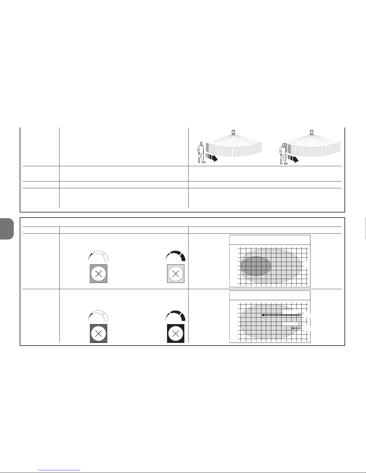
PT1 Microwave sensor area setting
from 6 to 12 m
PT2 Delay after intrusion in sensitive area
before alarm
1234 5678 9101112
0
1
2
3
4
4
3
2
1
0
1
2
3
4
4
3
2
1
2,5 sec.
0,25 sec.
Dip 4 = OFF Signalling leds active
Dip 4 = ON Signalling leds off
Dip 5 Not used
Dip 6 = OFF Temperature compensation deactivated
Dip 6 = ON Temperature compensation activated
It automatically increases sensitivity of the PIR when the
ambient temperature exceeds 30°C. Do not activate this
function unless absolutely necessary.
m
m
maximum
minimum
Range
m
Delay
minimum maximum
minimum maximum
Caution! – Led signalling increases battery consum-
ption.
Page 7
EN
English - 5
3.2 - Signals
HSDOM21 is equipped with 1 three-colour led and a warning buzzer.
The infrared detector is always active and in the event of
intrusion detection (green led LIT), it immediately activates
the microwave detector (orange led lit); if this also confirms
the presence of a moving body, the alarm status is generat-
ed (red led lit).
The low battery signal is activated 15-30 days in advance
before they are totally discharged. However, the batteries
should be replaced as soon as possible after this signal.
When the batteries are partially discharged, correct alarm
signals are not always guaranteed.
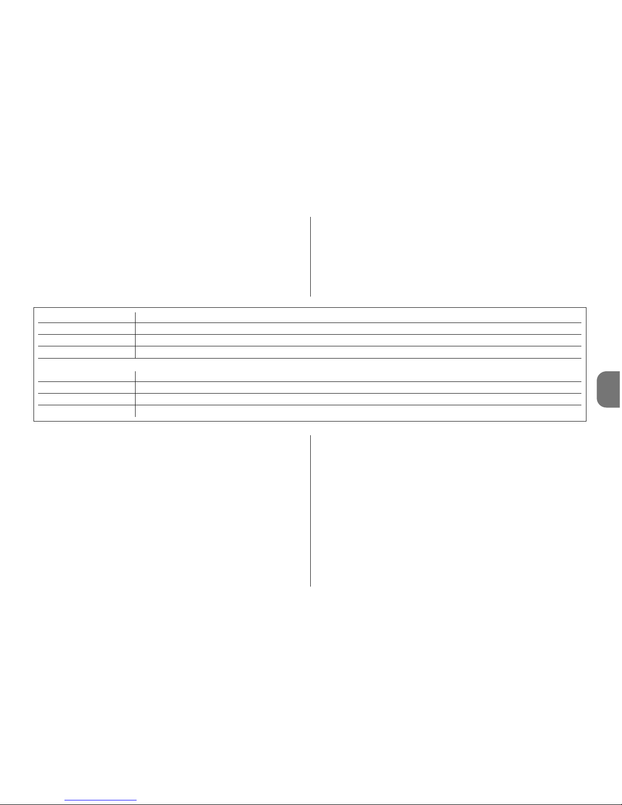
LED Function
Green Detection from infrared sensor (PIR = OK)
Orange Intrusion delay in progress ( MW = ?)
Red Intrusion alarm (PIR+MW = OK)
Buzzer Function
1 Beep Alarm signal (intrusion, tampering etc.)
3+3 Beeps Sensor programming (battery insertion)
5 Beep Low battery signal
4 - BATTERY REPLACEMENT
Caution! – Never use new battery models different from
the specified version. The batteries must all be replaced
at the same time (with new ones). Never combine batteries of different brands or models. Never use rechargeable batteries.
Caution! – Before detaching the detector from the support bracket, the control unit must be set to “CONTROL
UNIT TEST ” mode to prevent improper tampering alarm
signals.
01. To detach the detector from the support bracket, use the
relative release lever (fig. 3).
02. Slide the detector by approx. 5 mm upwards to move it
away from the support (fig. 3).
03. Open the housing by loosening the 4 rear screws (fig. 5);
04. Open the battery compartment as shown in fig. 6 and
replace the batteries. Observe the specified polarity.
05. Close the housing by tightening the 4 rear screws (fig. 8)
and connect the HSDOM21 to the fixing bracket (fig. 9).
5 - BATTERY DISPOSAL
Caution! – The batteries used in this alarm system, also if
discharged, contain pollutant substances and therefore must
not be disposed of as household waste. Dispose of accord-
Page 8
EN
6 - English
CE DECLARATION OF CONFORMITY
Note - The contents of this declaration correspond to declarations in the official document
deposited at the registered offices of Nice S.p.a. and in particular to the last revision available
before printing this manual. The text herein has been re-edited for editorial purposes.
Number: 331/HSDOM21 Revision: 0
The undersigned, Luigi Paro, in the role of Managing Director, declares under
his sole responsibility, that the product:
Manufacturer’s Name: NICE s.p.a.
Address: Via Pezza Alta 13, Z.I. Rustignè, 31046 Oderzo (TV)
Italy
Type: Dual technology infrared detector via radio
Models: HSDOM21
Accessories:
conforms to the essential requirements stated in article 3 of the following EC
directive, for the intended use of products:
• 1999/5/EC; DIRECTIVE 1999/5/EC OF THE EUROPEAN PARLIAMENT AND
COUNCIL of 9 March 1999 regarding radio equipment and telecommunications terminal equipment and the mutual recognition of their conformity
According to the following harmonised standards
Health protection: EN 50371:2002; electrical safety: EN 60950-1:2006; electromagnetic compatibility: EN 301 489-1V1.8.1:2008; EN 301 489-3V1.4.1:2002;
radio spectrum: EN 300220-2V2.1.2:2007, EN300440-2V1.3.1.:2009
In accordance with the directive 1999/5/EC (appendix V), the product is class
1 and marked:
The product also conforms to the requirements of the following EC directives:
• 2004/108/EEC (ex directive 89/336/EEC) ; DIRECTIVE 2004/108/EEC OF
THE EUROPEAN PARLIAMENT AND COUNCIL of 15 December 2004 regarding the approximation of member state legislation related to electromagnetic
compatibility, repealing directive 89/336/EEC
According to the following harmonised standards:
EN 50130-4:1995+A1:1998+A2:2003
Oderzo, 20.11.09
Ing. Luigi Paro (Managing Director)
0682
ing to separate waste collection procedures as envisaged by
local current standards.
6 - TECHNICAL SPECIFICATIONS
Warnings: • All technical specifications stated in this section refer to an
ambient temperature of 20°C (± 5°C). • Nice S.p.a. reserves the right
to apply modifications to products at any time when deemed necessary, maintaining the same intended use and functionality.
■ Type: volumetric detector with dual technology; infrared
(PIR) and microwave radar (MW), designed for use in external environments Protection against opening and removal ■
Power supply: 4.5V with 3 type AA 1.5V batteries or equivalent ■ Current absorption: 70 µA on standby - 40 mA in
transmission ■ Autonomy: estimated at 2 years (with Dip 4
set to ON), with low battery signal. ■ Radio transmission:
digital communication, in dual band frequency (433 and 868
Mhz) with quartz control; devices pre-encoded in the factory
and managed in self-learning mode ■ Radio range: 100 m
in open field free of disturbance or approx. 20 m inside buildings ■ Insulation: class III ■ Microwave Frequency: 9.9
GHz ■ Maximum microwave power: < 20 mW (compliant
with EN 50371); for maximum continuous time of 5s ■
Housing protection rating: IP 65 ■ Operating temperature: from -25°C to +55 °C ■ Use in environment class: II
■ Assembly: wall-mounted ■ Dimensions (mm): 158 x 83
x 50. ■ Weight: 0.37 Kg
Page 9

ITALIANO
Istruzioni originali
AVVERTENZE SPECIFICHE
• Installare il prodotto in una posizione difficilmente raggiungibile per evitarne il danneggiamento intenzionale.
• Non installare il prodotto vicino a possibili turbolenze d’aria
calda o fredda e dove ci sono animali a sangue caldo (fig 1).
• Se l’ambiente da proteggere è frequentato da animali do mestici, è necessario posizionare HSDOM21 ad un’altezza
adeguata e direzionato correttamente in modo da mantenere l’area di sensibilità, a 50-70 cm da terra, come indicato in fig 2 (vista verticale); eventualmente, è possibile ridurre
anche il valore della sensibilità del sensore.
• Non installare HSDOM21 in luoghi colpiti dal sole diretto,
per evitare che si surriscaldi internamente; il sole non provoca danneggiamenti al prodotto ma una variazione della sensibilità del rivelatore infrarosso falsificando così, gli effetti
della compensazione della temperatura ambientale che è
diversa da quella interna al prodotto.
• Non utilizzare HSDOM21 per proteggere aree esterne sottoposte alle intemperie come ad esempio neve o pioggia
battente; quest’ultime potrebbero causare allarmi impropri.
HSDOM21 è un rivelatore volumetrico a doppia tecnologia
ad infrarossi e radar a microonde. È predisposto per coprire
una area di dimensioni fino a 12 m e con una apertura angolare di 90°; dispone della regolazione della sensibilità, del tipo
di allarme (im mediato o al secondo impulso) e della protezione contro apertura e asportazione. È adatto all’uso in a m
-
bienti esterni protetti
. Ogni altro uso è da considerarsi im -
proprio e vietato! Nice non risponde dei danni risultanti
da un uso im proprio del prodotto, diverso da quanto pre visto nel presente manuale.
1 - FUNZIONAMENTO
HSDOM21 è un rivelatore volumetrico a doppia tecnologia
(PIR = Passive Infra-Red detector + MW = Micro Wave doppler detector) studiato per rivelare una persona in movimento, all’interno di una zona protetta. Le due diverse tecnologie, consentono di ridurre la possibilità che si verifichino allarmi impropri dovuti a fattori ambientali; per un funzionamento
ottimale è necessario posizionare e regolare correttamente il
prodotto. Nei casi più estremi, per ridurre ulteriormente gli
allarmi impropri, è possibile installare due rilevatori nella stessa area ma contrapposti tra loro e programmando la centrale sulla funzione “AND” (vedere manuale istruzioni della centrale). L’utilizzo dello snodo orientabile mod. HSA3 (ac cessorio opzionale) consente un corretto posizionamento e orientamento del prodotto, in particolare per il fissaggio ad angolo (vedere cap. 2 - Installazione).
HSDOM21, funziona con 3 pile alcaline tipo AA; non dispone di
nessun collegamento elettrico verso l’esterno e nel caso di rilevazione d’intrusione, trasmette l’allarme via radio alla centrale.
Nel prodotto, il rivelatore d’infrarossi è sempre attivo e nel caso
di rilevazione d’intrusione (led verde acceso) attiva im mediatamente il rivelatore a microonde (led aracio acceso); se anche
questo, conferma l’esistenza di un corpo in movimento, si
genera lo stato di allarme (led rosso acceso).
Attenzione! – Quando viene rimosso il coperchio superiore
di HSDOM21, il sistema rimane sempre attivo.
Il rivelatore dispone di protezioni contro l’asportazione e contro l’apertura.
Italiano - 1
IT
Page 10
HSDOM21 trasmette alla centrale un segnale di esistenza in
vita ogni 40 minuti circa; che è necessario per la “funzione
supervisione” presente sulla centrale.
2 - INSTALLAZIONE
Avvertenze
• Determinare la posizione e l’altezza di fissaggio di HSDOM21,
in funzione dell’area di protezione che si desidera ottenere:
fare riferimento alla fig. 2.
• Verificare con attenzione la forma della zona da proteggere; nel caso di dubbi, prima di effetture il fissaggio definitivo, si consiglia di fissare provvisoriamente il prodotto effettuando le prove e le eventuali regolazioni necessarie.
• La particolare conformazione della lente del sensore infrarosso, crea un’area sensibile a “tenda”. Se il rivelatore è posto in
verticale l’area sensibile è
orizzontale (pa rallela al terreno); se invece il rivelatore è
posto in orizzontale allora
l’area sensibile è verticale
(pro tezione a tenda con ef fetto barriera).
È importante valutare con
attenzione questi aspetti in
funzione dell’area da proteggere, in relazione ad una even tuale insensibilità agli animali e in funzione del rischio dell’attraversamento veloce dell’area.
• Se si desidera installare il prodotto ad angolo, è necessario
l’uso dello snodo orientabile mod. HSA3 (accessorio opzio nale): Attenzione! – Utilizzando lo snodo viene persa, in parte, la protezione antiasportazione perché il magnete rimane
sulla staffa. Se non viene usato il magnete occorre esclude-
re la protezione, ponendo il dip-switch 5 = ON
01. Decidere la posizione di fissaggio della staffa, verificando
che sia compatibile con l’ingombro totale del rivelatore:
deve essere possibile raggiungere la levetta per lo sgancio (fig. 3) ed essere disponibile lo spazio per poter sgan-
ciare ed aggangiare il rivelatore.
02.A – Fissaggio a muro: eseguire due fori per l’inserimento dei tasselli di fissaggio e un foro per il magnete,
che serve per la protezione “antiasportazione”. Poi, fissare la staffa con gli appositi tasselli (fig. 4-A);
02. B – Fissaggio ad angolo con snodo mod. HSA3: fissare lo snodo al muro (vedere proprio manuale istruzioni) e
poi, fissare la staffa allo snodo come indicato in (fig. 4-B);
03. Aprire il contenitore allentando le 4 viti posteriori (fig. 5);
04. Predisporre la centrale per l’apprendimento di HSDOM21
(vedere manuale istruzioni della centrale);
05. Aprire il vano porta pile come indicato in fig. 6 e strappa-
re la linguetta isolante che mantiene le pile scollegate:
HSDOM21, emette due serie di 3 beep e inizia la sua programmazione in auto-apprendimento; questa, viene confermata da 1 beep emesso dalla centrale (4 beep indicano che il dispositivo è già programmato).
06. Eseguire la programmazione dei dip switch (fig. 7)e la
regolazione dei trimmer (fig. 7) facendo riferimento al
cap. 3 - Programmazione; poi, eseguire il “Test” di fun-
zionamento, vedere paragrafo 3.1.
07. Richiudere il contenitore (fig. 8) ed agganciare HSDOM21
alla sua staffa di fissaggio (fig. 9).
3 - PROGRAMMAZIONE
HSDOM21 dispone di n° 5 “dip-switch” (fig. 7) che permet-
IT
2 - Italiano
verticale
orizzontale
Page 11
tono di programmare alcuni parametri di funzionamento e di
n° 2 “trimmer” di regolazione (PT1 e PT2 - fig. 7): vedere
Tabella 1 e Tabella 2.
3.1 - Procedura di programmazione e “Test” di funzionamento
01. Per primo, programmare il rivelatore infrarosso con n° 1
impulsi per allarme: dip-switch 3 = OFF (Tabella 1).
02. Poi, programmare la “sensibilità” del rivelatore infrarosso
PIR: dip-switch 2 con il valore minimo
ne ces sario (Ta -
bella 1).
03. Regolare al minimo
, il valore del “ritardo dopo l’intrusione”:
trimmer PT2 (fig. 7).
04. Regolare il valore della sensibilità del rivelatore a micro-
onde (trimmer PT1 - fig. 7)
05. Verificare la copertura dell’area protetta: effettuare dei
brevi movimenti al l’interno dell’area e controllare le se gna lazioni emesse dal led. Se necessario, regolare il va lore della sensibilità. Attenzione! – La lente del sensore
infrarosso è posizionata fissa sul coperchio e quindi, le
prove di rilevazione devono essere effettuate con l’apparecchio chiuso.
06. Dopo aver regolato la sensibilità, per ridurre le possibilità
che si verifichino allarmi impropri, si consiglia di regolare
il dip-switch 3 = ON (n° 2 impulsi per allarme).
07. Per lo stesso motivo, regolare al massimo
il valore del
“ritardo dopo l’intrusione”: trimmer PT2 (fig. 7), compatibilmente con le esigenze di rilevazione.
08. Terminata la verifica di funzionamento si consiglia di porre il
dip-switch 4 = ON per spegnere la segnalazione del led.
Tabella 1
Dip Switch Funzione Note
Dip 1 Non usato
Dip 2 = OFF Area sensibile sensore infrarosso fino a 6 m
Dip 2 = ON Area sensibile sensore infrarosso fino a 12 m
Dip 3 = OFF N° impulsi infrarosso per allarme = 1
Dip 3 = ON N° impulsi infrarosso per allarme = 2
123456789101112
0
1
2
3
4
4
3
2
1
IT
Italiano - 3
m
m
Page 12
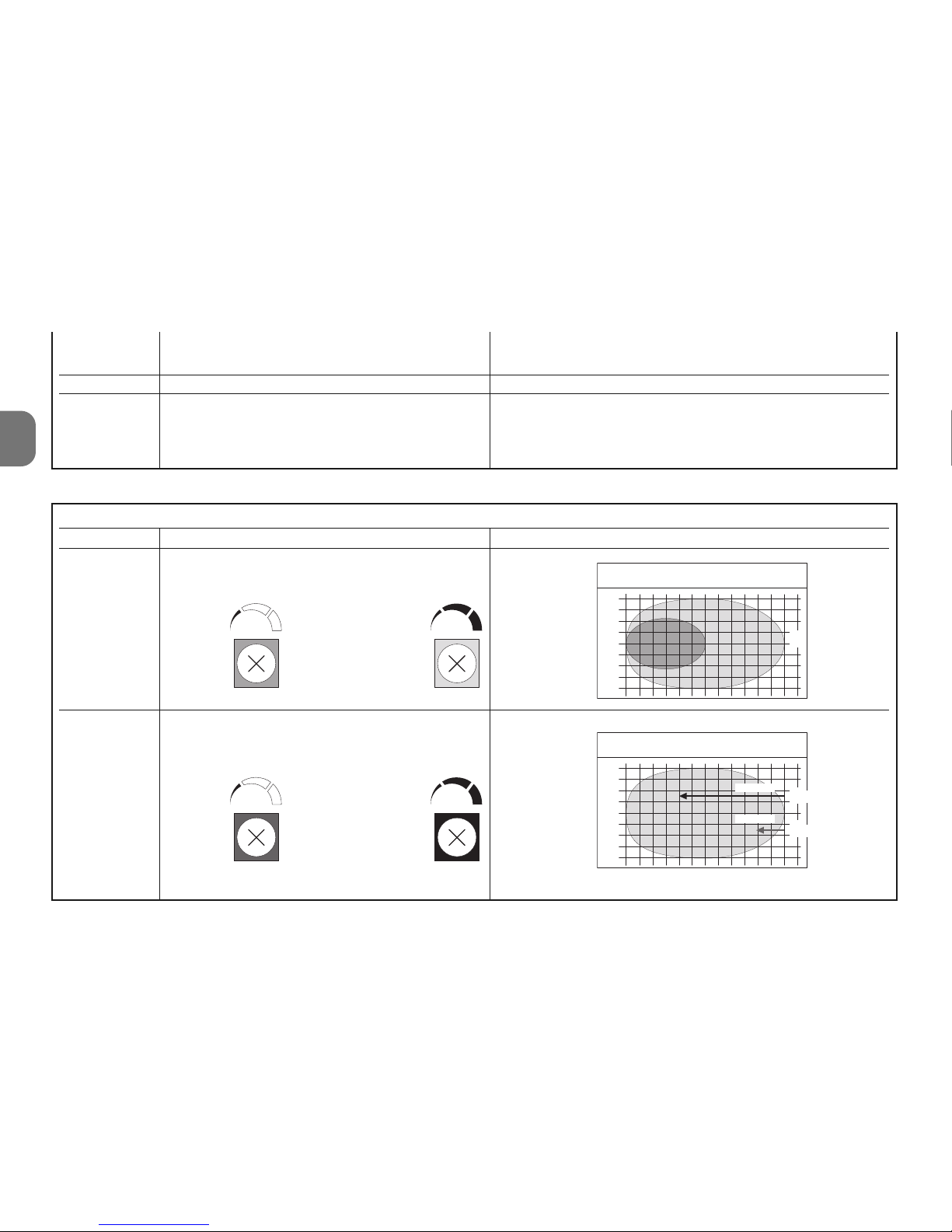
Tabella 2
Trimmer Funzione Note
PT1 Regolazione area sensore microonde
da 6 a 12 m
PT2 Ritardo dopo l’intrusione nell’area sensibile
prima dell’allarme
1234 56 78 9101112
0
1
2
3
4
4
3
2
1
0
1
2
3
4
4
3
2
1
2,5 sec.
0,25 sec.
IT
4 - Italiano
Dip 4 = OFF Led segnalazione attivi
Dip 4 = ON Led segnalazione spenti
Dip 5 Non usato
Dip 6 = OFF Compensazione temperatura disattiva
Dip 6 = ON Compensazione temperatura attiva
Attenzione! – La segnalazione dei led provoca maggiore consumo delle pile.
Provoca l’aumento automatico della sensibilità del PIR
quando la temperatura ambiente supera i 30°C. Non
attivare questa funzione senza necessità.
m
m
massimo
minimo
Portata
m
Ritardo
minimo massimo
minimo massimo
Page 13
3.2 - Segnalazioni
HSDOM21, dispone di n° 1 led a 3 colori e di un buzzer che
emette segnalazioni acustiche.
Il rivelatore d’infrarossi è sempre attivo e nel caso di rilevazione
d’intrusione (led verde acceso) attiva im mediatamente il rivelatore a microonde (led aracio acceso); se anche questo, conferma l’esistenza di un corpo in movimento, si genera lo stato
di allarme (led rosso acceso).
La segnalazione di pile scariche avviene con un anticipo di
15-30 giorni rispetto al totale esaurimento. Comunque, è
preferibile sostituirle al più presto. Quando le pile sono parzialmente scariche, potrebbe non avvenire la corretta segnalazione di allarme.
LED Funzione
Verde Rilevazione da sensore infrarosso (PIR = OK)
Arancio Ritardo intrusione in corso ( MW = ?)
Rosso Allarme intrusione (PIR+MW = OK)
Buzzer Funzione
1 Beep Segnalazione allarme (intrusione, manomissione…)
3+3 Beep Programmazione sensore (inserimento pile)
5 Beep Segnalazione pile scariche
4 - SOSTITUZIONE PILE
Attenzione! – Non utilizzare per nessun motivo pile di -
verse dal tipo previsto. Le pile devono essere sostituite
tutte insieme (con elementi nuovi). Non mischiare pile di
marca o modello diversi. Non usare pile ricaricabili.
Attenzione! – Prima di sganciare il rivelatore dalla staffa
di supporto, è necessario impostare la centrale in modalità “TEST CENTRALE” per evitare di provocare inutili
segnalazioni di manomissione.
01. Per sganciare il rivelatore dalla staffa di supporto, è ne cessario agire sull’apposita levetta di aggancio (fig. 3).
02. Far scorrere il rivelatore di circa 5 mm verso l’alto e poi
allontanarlo dalla staffa di supporto (fig. 3).
03. Aprire il contenitore allentando le 4 viti posteriori (fig. 5).
04. Aprire il vano porta pile come indicato in fig. 6 e sostitui-
re le pile. Rispettare la polarità indicata.
05. Richiudere il rivelatore avvitando le 4 viti posteriori (fig.
8) ed agganciare HSDOM21 alla sua staffa di fissaggio
(fig. 9).
5 - SMALTIMENTO PILE E BATTERIE
Attenzione! – Le pile e le batterie contenute nei dispositivi
che compongono il presente sistema di allarme, anche se
scariche, contengono sostanze inquinanti e quindi non de vono essere gettate nei rifiuti comuni. Occorre smaltirle utiliz-
Italiano - 5
IT
Page 14
6 - Italiano
IT
DICHIARAZIONE CE DI CONFORMITÀ
Nota - Il contenuto di questa dichiarazione corrisponde a quanto dichiarato nell’ultima revisione
disponibile, prima della stampa di questo manuale, del documento ufficiale depositato presso la
sede di Nice Spa. Il presente testo è stato riadattato per motivi editoriali.
Numero: 331/HSDOM21 Revisione: 0
Il sottoscritto Luigi Paro in qualità di Amministratore Delegato, dichiara sotto la
propria responsabilità che il prodotto:
Nome produttore: NICE s.p.a.
Indirizzo: Via Pezza Alta 13, Z.I. Rustignè, 31046 Oderzo (TV) Italia
Tipo: Rilevatore ad infrarossi a doppia tecnologia via radio
Modelli: HSDOM21
Accessori:
Risulta conforme ai requisiti essenziali richiesti dall’articolo 3 dalla seguente
direttiva comunitaria, per l’uso al quale i prodotti sono destinati:
• 1999/5/CE DIRETTIVA 1999/5/CE DEL PARLAMENTO EUROPEO E DEL
CONSIGLIO del 9 marzo 1999 riguardante le apparecchiature radio e le apparecchiature terminali di telecomunicazione e il reciproco riconoscimento della
loro conformità
Secondo le seguenti norme armonizzate
protezione della salute: EN 50371:2002; sicurezza elettrica: EN 609501:2006; compatibilità elettromagnetica: EN 301 489-1V1.8.1:2008; EN 301
489-3V1.4.1:2002; spettro radio: EN 300220-2V2.1.2:2007, EN3004402V1.3.1.:2009
In accordo alla direttiva 1999/5/CE (allegato V), il prodotto risulta di classe 1 e
marcato:
Inoltre il prodotto risulta conforme a quanto previsto dalle seguenti direttive
comunitarie:
• 2004/108/CEE(ex direttiva 89/336/CEE) DIRETTIVA 2004/108/CE DEL PARLAMENTO EUROPEO E DEL CONSIGLIO del 15 dicembre 2004 concernente
il ravvicinamento delle legislazioni degli Stati membri relative alla compatibilità
elettromagnetica e che abroga la direttiva 89/336/CEE
Secondo le seguenti norme armonizzate:
EN 50130-4:1995+A1:1998+A2:2003
Oderzo, 20 novembre 2009
Ing. Luigi Paro (Amministratore Delegato)
0682
zando i metodi di raccolta ‘separata’ previsti dalle normative
vigenti nel vostro territorio.
6 - CARATTERISTICHE TECNICHE
Avvertenze: • Tutte le caratteristiche tecniche riportate, sono riferite ad
una temperatura ambientale di 20°C (± 5°C). • Nice S.p.a. si riserva il
diritto di apportare modifiche al prodotto in qualsiasi momento lo riterrà necessario, mantenendone comunque la stessa funzionalità e destinazione d’uso.
■ Tipologia: rivelatore volumetrico a doppia tecnologia, infra-
rossi (PIR) e radar a microonde (MW); per l’uso in ambienti
esterni. Protezione contro apertura e asportazione ■ Alimen-
tazione: 4,5V con 3 pile 1,5V tipo AA o equivalenti ■ Corrente assorbita: 70 µA a riposo - 40 mA in trasmissione ■
Autonomia: stimata 2 anni (con Dip 4 = ON), con segnala-
zione di pila scarica. ■ Trasmissione radio: comunicazione
digitale, in doppia frequenza “DualBand” (433 e 868MHz)
controllata al quarzo; dispositivi pre-codificati in fabbrica e
gestiti in autoapprendimento ■ Portata radio: 100 m in spa-
zio libero ed in assenza di disturbi; circa 20 m all’interno di edifici ■ Isolamento: classe III ■ Frequenza microonda: 9,9
GHz ■ Potenza massima microonda: < 20 mW (conforme a
EN 50371); per un tempo massimo continuativo di 5s ■ Gra-
do di protezione del contenitore: IP 65 ■ Temperatura di
funzionamento: da -25°C a +55 °C ■ Utilizzo in ambienti
di classe ambientale: II ■ Montaggio: a parete ■ Dimen-
sioni (mm): 158 x 83 x 50 ■ Peso: 0,37 Kg
Page 15

FR
Français - 1
Instructions originales
FRANÇAIS
RECOMMANDATIONS SPÉCIFIQUES
• Installer le produit dans une position difficile à atteindre
pour en éviter l’endommagement intentionnel.
• Ne pas installer le produit dans un endroit exposé aux cou-
rants d’air chaud ou froid et fréquenté par des animaux à
sang chaud (fig. 1).
• Si l’endroit à protéger est fréquenté par des animaux
domestiques, il faut positionner HSDOM21 à une hauteur
adéquate et l’orienter correctement de manière à maintenir
la zone de sensibilité, à 50-70 cm du sol, comme indiqué
dans la fig. 2 (vue verticale) ; éventuellement, il est possible
de réduire aussi la valeur de la sensibilité du détecteur.
• Ne pas installer HSDOM21 dans des endroits exposés au
rayonnement solaire direct, pour éviter une surchauffe
interne ; le soleil n’endommage pas l’appareil mais produit
une variation de la sensibilité du détecteur infrarouge en
faussant ainsi les effets de la compensation de la température ambiante qui est différente de celle à l’intérieur de l’appareil.
• Ne pas utiliser HSDOM21 pour protéger des zones exté-
rieures soumises aux intempéries comme par exemple la
neige ou la pluie battante ; ces agents climatiques pourraient provoquer des alarmes impropres.
HSDOM21 est un détecteur volumétrique à double technologie à infrarouge et radar à micro-ondes. Il est prévu pour
couvrir une zone mesurant jusqu’à 12 m et avec une couverture angulaire de 90° ; il dispose du réglage de la sensibilité,
du type d’alarme (immédiate ou à la deuxième impulsion) et
de la protection contre l’ouverture et le sabotage. Il est indiqué pour une utilisation dans des lieux extérieurs protégés
.
Toute autre utilisation doit être considérée comme im propre et interdite ! Nice ne répond pas des dommages
résultant d’une utilisation impropre des produits, différente de ce qui est prévu dans le présent guide.
1 - FONCTIONNEMENT
HSDOM21 est un détecteur volumétrique à double technologie (PIR = Passive Infra-Red detector + MW = Micro Wave
doppler detector) conçu pour détecter une personne en
mouvement, à l’intérieur d’une zone protégée. Les deux
technologies différentes permettent de réduire la possibilité
que se vérifient des alarmes impropres dues à des facteurs
ambiants ; pour un fonctionnement optimal il faut positionner
et régler correctement le produit. Dans les cas les plus
extrêmes, pour réduire ultérieurement les alarmes impropres,
il est possible d’installer deux détecteurs dans la même zone
mais opposés l’un à l’autre, en programmant la centrale sur
la fonction « AND » (voir notice d’instructions de la centrale).
L’utilisation du support orientable mod. HSA3 (accessoire en
option) permet un positionnement correct et l’orientation du
produit, en particulier pour la fixation dans un angle (voir
chap. 2 - Installation).
HSDOM21 fonctionne avec 3 piles alcalines type AA ; il ne
dispose d’aucune connexion électrique vers l’extérieur et en
cas de détection d’intrusion, il transmet l’alarme par radio à
la centrale.
Dans le produit, le détecteur d’infrarouges est toujours actif et
en cas de détection d’intrusion (led verte allumée) il active
immédiatement le détecteur à micro-ondes (led orange allu-
Page 16
2 - Français
FR
mée) ; si ce dernier confirme lui aussi la présence d’un corps en
mouvement, l’état d’alarme se déclenche (led rouge allumée).
Attention ! – Quand le couvercle supérieur de HSDOM21
est enlevé, le système reste toujours actif.
Le détecteur dispose de protections contre le sabotage et
contre l’ouverture.
HSDOM21 transmet à la centrale un signal de bon fonctionnement toutes les 40 minutes environ qui est nécessaire
pour la « fonction supervision » présente sur la centrale.
2 - INSTALLATION
Recommandations
• Déterminer la position et la hauteur de fixation de HSDOM21,
en fonction de la surface de protection que l’on souhaite
obtenir : se référer à la fig. 2.
• Vérifier attentivement la forme de la zone à protéger ; en
cas de doute, avant la fixation définitive, il est conseillé de
fixer provisoirement le produit en effectuant les essais et
les éventuels réglages nécessaires.
• La conformation particulière de la lentille du détecteur
infrarouge, crée une surfa ce sensible type « rideau ». Si le
détecteur est placé à la verticale la surface sensible est
horizontale (parallèle au
sol) ; si par contre le détecteur est placé à l’horizontale, la surface sensible est
verticale (protection rideau
avec effet barrière).
Il est important d’évaluer at tentivement ces aspects en fonction de la zone à protéger,
suivant l’insensibilité aux animaux et en fonction du risque
de traversée rapide de la zone.
• Si l’on souhaite installer le produit en angle, il faut utiliser le
support orientable mod. HSA3 (accessoire en option) :
Attention ! – quand on utilise le support orientable, on
perd, en partie, la protection antisabotage car l’aimant
reste sur la patte. Si l’aimant n’est pas utilisé, il faut exclure
la protection, en réglant le dip-switch 5 = ON
01. Décider la position de fixation de la patte en vérifiant
qu’elle est compatible avec l’encombrement total du
détecteur : il doit être possible d’atteindre le levier pour le
décrochage (fig. 3) et il doit y avoir suffisamment de
place pour pouvoir décrocher et accrocher le détecteur.
02.A – Fixation au mur : effectuer deux trous pour les
chevilles de fixation et un trou pour l’aimant, servant à la
protection « antisabotage ». Fixer ensuite la patte à l’aide
des chevilles (fig. 4-A) ;
02. B – Fixation en angle avec support mod. HSA3 :
fixer le support au mur (voir notice d’instructions) puis fixer
la patte au support en suivant les indications (fig. 4-B) ;
03. Ouvrir le boîtier en dévissant les 4 vis arrière (fig. 5) ;
04. Préparer la centrale pour la reconnaissance de
HSDOM21 (voir guide d’instructions de la centrale) ;
05. Ouvrir le logement de la pile comme indiqué fig. 6 et
arracher la languette isolante qui maintient les piles
déconnectées : HSDOM21 émet deux séries de 3 bips
et commence sa programmation en reconnaissance
automatique ; opération qui est confirmée par 1 bip émis
par la centrale (4 bips indiquent que le dispositif est déjà
programmé).
06. Effectuer la programmation des dip-switchs (fig. 7) et le
réglage des trimmers (fig. 7) en se référant au chap. 3
Programmation ; puis effectuer le « Test » de fonctionne-
verticale
horizontale
Page 17
FR
ment, voir paragraphe 3.1.
07. Refermer le boîtier (fig. 8) et accrocher HSDOM21 à sa
patte de fixation (fig. 9).
3 - PROGRAMMATION
HSDOM21 dispose de n° 5 « dip-switchs » (fig. 7) qui permettent de programmer certains paramètres de fonctionnement et de n° 2 « trimmers » de réglage (PT1 et PT2 - fig.
7) : voir Tableau 1 et Tableau 2.
3.1 - Procédure de programmation et « Test » de
fonctionnement
01. En premier, programmer le détecteur infrarouge avec 1
impulsion pour déclencher alarme : dip-switch 3 = OFF
(Tableau 1).
02. Programmer ensuite la « sensibilité » du détecteur infrarouge PIR : dip-switch 2 avec la valeur minimum
néces-
saire (Tableau 1).
03. Régler au minimum
, la valeur du « retard après l’intru-
sion » : trimmer PT2 (fig. 7).
04. Régler la valeur de la sensibilité du détecteur à microondes (trimmer PT1 - fig. 7)
05. Vérifier la couverture de la zone protégée : effectuer de
brefs mouvements à l’intérieur de la zone et contrôler les
signalisations émises par la led. Si nécessaire, régler la
valeur de la sensibilité. Attention ! – La lentille du détecteur infrarouge est positionnée fixe sur le couvercle, par
conséquent, les essais de détection doivent être faits
avec l’appareil fermé.
06. Après avoir réglé la sensibilité, pour réduire les risques
d’alarmes impropres, il est conseillé de régler le dip-
switch 3 = ON (2 impulsions pour déclencher l’alarme).
07. Pour la même raison, régler au maximum
la valeur du
« retard après l’intrusion » : trimmer PT2 (fig. 7), de
manière compatible avec les exigences de détection.
08. Après avoir terminé la vérification de fonctionnement il
est conseillé de placer le dip-switch 4 = ON pour éteindre la signalisation de la led.
Tableau 1
Dip-switch Fonction Notes
Dip 1 Non utilisé
Dip 2 = OFF Zone sensible détecteur infrarouge jusqu’à 6 m
Dip 2 = ON Zone sensible détecteur infrarouge jusqu’à 12 m
123456789101112
0
1
2
3
4
4
3
2
1
m
m
Français - 3
Page 18
4 - Français
FR
Tableau 2
Trimmer Fonction Notes
PT1 Réglage zone détecteur micro-ondes
de 6 à 12 m
PT2 Retard après l’intrusion dans la zone
sensible avant l’alarme
1234 56 78 9101112
0
1
2
3
4
4
3
2
1
0
1
2
3
4
4
3
2
1
2,5 sec.
0,25 sec.
Dip 3 = OFF Nombre d’impulsions infrarouge pour alarme = 1
Dip 3 = ON Nombre d’impulsions infrarouge pour alarme = 2
Dip 4 = OFF Leds signalisation actives
Dip 4 = ON Leds signalisation éteintes
Dip 5 Non utilisé
Dip 6 = OFF Compensation température désactivée
Dip 6 = ON Compensation température active
Attention ! – La signalisation des leds provoque une
plus grande consommation des piles.
Elle provoque l’augmentation automatique de la sensibilité du PIR quand la température ambiante dépasse 30°C.
Ne pas activer cette fonction si cela n’est pas nécessaire.
m
m
maximum
minimum
Portée
m
Retard
minimum maximum
minimum maximum
Page 19
FR
Français - 5
LED Fonction
Verte Détection par détecteur infrarouge (PIR = OK)
Orange Retard intrusion en cours ( MW = ?)
Rouge Alarme intrusion (PIR+MW = OK)
Avertisseur Fonction
1 Beep Signalisation alarme (intrusion, sabotage…)
3+3 Bips Programmation détecteur (introduction piles)
5 Bips Signalisation piles épuisées
4 - REMPLACEMENT PILES
Attention ! – N’utiliser sous aucun prétexte des piles
différentes du type prévu. Les piles doivent être remplacées toutes ensemble (par des piles neuves). Ne pas
mélanger les piles de marque ou modèle différents. Ne
pas utiliser de piles rechargeables.
Attention ! – Avant de décrocher le détecteur de la pat te de support, il faut mettre la centrale en mode « TEST
CENTRALE » pour éviter de provoquer des si gna li sa tions de sabotage inutiles.
01. Pour décrocher le détecteur de la patte de support, il
faut agir sur le levier d’accrochage (fig. 3).
02. Faire coulisser le détecteur d’environ 5 mm vers le haut
puis l’éloigner de la patte de support (fig. 3).
03. Ouvrir le boîtier en dévissant les 4 vis arrière (fig. 5) ;
04. Ouvrir le logement des piles comme indiqué fig. 6 et
remplacer les piles. Respecter la polarité indiquée.
05. Refermer le détecteur en vissant les 4 vis arrière (fig. 8)
et accrocher HSDOM21 à la patte de fixation (fig. 9).
5 - MISE AU REBUT DES PILES ET BATTERIES
Attention ! – Les piles et les batteries présentes dans les
dispositifs qui composent le présent système d’alarme,
même si elles sont épuisées, contiennent des substances
polluantes, elles ne doivent donc pas être jetées avec les
ordures ménagères. Il faut les mettre au rebut en adoptant
3.2 - Signalisations
HSDOM21 dispose d’1 led à 3 couleurs et d’un avertisseur
qui émet des signalisations acoustiques.
Le détecteur d’infrarouges est toujours actif et en cas de
détection d’intrusion (led verte allumée), il active immédiatement le détecteur à micro-ondes (led orange allumée) ; si ce
dernier confirme lui aussi la présence d’un corps en mouve-
ment, l’état d’alarme se déclenche (led rouge allumée).
La signalisation de piles épuisées est donnée avec une
avance de 15-30 jours par rapport à l’épuisement total.
Dans tous les cas, il est préférable de les remplacer au plus
vite. Quand les piles sont partiellement épuisées, la signalisation de l’alarme pourrait être compromise.
Page 20
FR
6 - Français
DÉCLARATION CE DE CONFORMITÉ
Note - Le contenu de cette déclaration de conformité correspond à ce qui est déclaré dans la dernière révision disponible - avant l’impression de la présente notice technique – du document officiel déposé au siège de Nice S.p.a. Le présent texte a été réélaboré pour des raisons d’édition.
Numéro : 331/HSDOM21 Révision : 0
Je soussigné Luigi Paro en qualité d’Administrateur Délégué, déclare sous
mon entière responsabilité que le produit :
Nom producteur : NICE s.p.a.
Adresse : Via Pezza Alta, 13, Z.I. Rustignè, 31046 Oderzo (TV) Italie
Type : Détecteur à infrarouge à double technologie par radio
Modèles : HSDOM21
Accessoires :
Est conforme aux critères essentiels requis par l’article 3 de la directive communautaire suivante, pour l’usage auquel ces produits sont destinés :
• 1999/5/CE DIRECTIVE 1999/5/CE DU PARLEMENT EUROPÉEN ET DU
CONSEIL du 9 mars 1999 concernant les équipements hertziens et les équipements terminaux de télécommunication et la reconnaissance mutuelle de
leur conformité
Selon les normes harmonisées suivantes :
protection de la santé : EN 50371:2002 ; sécurité électrique : EN 609501:2006 ; compatibilité électromagnétique : EN 301 489-1V1.8.1:2008 ; EN 301
489-3V1.4.1:2002 ; spectre radio : EN 300220-2V2.1.2:2007, EN3004402V1.3.1:2009
Conformément à la directive 1999/5/CE (annexe V), le produit résulte de
classe 1 et est marqué :
En outre, le produit est conforme à ce qui est prévu par les directives communautaires suivantes :
• 2004/108/CEE (ex directive 89/336/CEE) DIRECTIVE 2004/108/CE DU
PARLEMENT EUROPÉEN ET DU CONSEIL du 15 décembre 2004 concernant
l’harmonisation des législations des états membres relatives à la compatibilité
électromagnétique et qui abroge la directive 89/336/CEE
Selon les normes harmonisées suivantes :
EN 50130-4:1995+A1:1998+A2:2003
Oderzo, le 20 novembre 2009
Ing. Luigi Paro (Administrateur Délégué)
0682
les méthodes de collecte sélective prévues par les normes
en vigueur dans le pays d’utilisation.
6 - CARACTÉRISTIQUES TECHNIQUES
Avertissements : • Toutes les caractéristiques techniques indiquées
se réfèrent à une température ambiante de 20 °C (± 5 °C). • Nice
S.p.a. se réserve le droit d’apporter des modifications au produit à tout
moment si elle le jugera nécessaire, en garantissant dans tous les cas
les mêmes fonctions et le même type d’utilisation prévu.
■ Typologie : détecteur volumétrique à double technologie,
infrarouges (PIR) et radar à micro-ondes (MW) ; pour l’utilisation à l’extérieur. Protection contre l’ouverture et le sabotage
■ Alimentation : 4,5 V avec 3 piles 1,5 V type AA ou équiva -
lentes ■ Courant absorbé : 70 µA au repos - 40 mA en
émission ■ Autonomie : estimée à 2 ans (avec Dip 4 = ON),
avec signalisation de pile épuisée. ■ Transmission radio :
communication numérique, en double fréquence « DualBand » (433 et 868 Mhz) contrôlée par quartz ; dispositifs
précodés à l’usine et gérés en reconnaissance automatique
■ Portée radio : 100 m en espace libre et en l’absence de
perturbations ; environ 20 m à l’intérieur de bâtiments
■ Isolement : Classe III ■ Fréquence micro-onde : 9,9
GHz ■ Puissance maximum micro-onde : < 20 mW (con -
forme à EN 50371) ; pour un temps maximum continu de 5 s
■ Indice de protection du boîtier : IP 65 ■ Température
de fonctionnement : de -25°C à +55 °C ■ Utilisation dans
des environnements de classe : II ■ Montage : mural ■
Dimensions (mm) : 158 x 83 x 50 ■ Poids : 0,37 kg
Page 21

Instrucciones originales
ESPAÑOL
Español - 1
ES
ADVERTENCIAS ESPECÍFICAS
• Instale el producto en una posición difícil de alcanzar para
que no pueda ser dañado intencionalmente.
• No instale el producto cerca de posibles turbulencias de
aire caliente o fría y donde haya animales de sangre caliente (fig. 1).
• Si el local que hay que proteger estuviera frecuentado por
animales domésticos, habrá que colocar HSDOM21 a una
altura adecuada y dirigido correctamente a fin de mantener la zona de sensibilidad, a 50-70 cm del suelo, tal como
se muestra en la fig. 2 (vista vertical); de ser necesario,
también es posible reducir el valor de la sensibilidad del
sensor.
• No instale HSDOM21 en lugares donde dé el sol directo
para que no se recaliente internamente; el sol no provoca
da ños en el producto sino una variación de la sensibilidad
del detector infrarrojo, así falsificando los efectos de la
compensación de la temperatura ambiente que es diferente de aquella del interior del producto.
• No utilice HSDOM21 para proteger zonas exteriores ex puestas a la intemperie, por ejemplo nieve o lluvia intensa,
porque podrían provocar falsas alarmas.
HSDOM21 es un detector volumétrico de doble tecnología
por infrarrojos y radar por microondas. Está preparado para
cubrir una zona de hasta 12 m, con una abertura angular de
90°; dispone de regulación de la sensibilidad, tipo de alarma
(inmediata o en el segundo impulso) y de protección contra
la apertura y extracción. Es adecuado para ser utilizado en
entornos exteriores protegidos
. ¡Cualquier otra utilización
debe considerarse inadecuada y está prohibida! Nice no
responde de los daños que pudieran surgir si el producto se utilizara de manera inadecuada y diferente a la
indicada en este manual.
1 - FUNCIONAMIENTO
HSDOM21 es un detector volumétrico de doble tecnología
(PIR = Passive Infra-Red detector + MW = Micro Wave doppler detector) estudiado para detectar una persona en movimiento que haya entrado a una zona protegida. Las dos tecnologías permiten disminuir la posibilidad de que se activen
falsas alarmas debidas a factores ambientales; para un funcionamiento perfecto es necesario colocar y regular correctamente el producto. En los casos extremos, para disminuir
aún más la posibilidad de falsas alarmas, es posible instalar
dos detectores en la misma zona pero contrapuestos entre
sí, programando la central en la función “AND” (véase el
manual de instrucciones de la central). El uso de la rótula
orientable mod. HSA3 (accesorio opcional) permite colocar y
orientar correctamente el producto, especialmente para la
fijación en ángulo (véase el cap. 2 - Instalación).
HSDOM21 funciona con 3 pilas alcalinas tipo AA; no dispone
de ninguna conexión eléctrica al exterior y, en el caso de de tección de intrusión, transmite la alarma vía radio a la central.
En el producto, el detector de infrarrojos siempre está activo
y, en el caso de detección de intrusión (led verde encendido),
activa inmediatamente el detector de microondas (led naranja encendido); si también éste confirma la existencia de un
cuerpo en movimiento, se genera la condición de alarma (led
rojo encendido).
Page 22
2 - Español
ES
¡Atención! – Al quitar la tapa superior de HSDOM21, el sistema permanece siempre activo.
El detector dispone de protecciones contra la extracción y
contra la apertura.
HSDOM21 transmite a la central una señal de existencia de
vida cada 40 minutos aprox., que sirve para la “función
supervisión” presente en la central.
2 - INSTALACIÓN
Advertencias
• Determine la posición y la altura de fijación de HSDOM21,
de acuerdo con la zona de protección que se desea obtener: tome como referencia la fig. 2.
• Controle minuciosamente la forma de la zona que debe
proteger; si tuviera dudas, antes de fijar el aparato de fi nitivamente, se aconseja fijar provisoriamente el producto
realizando las pruebas y las regulaciones ne cesarias.
• La forma especial de la lente del sensor infrarrojo crea una
zona sensible tipo “cortina”. Si el detector está colocado
en posición vertical, la zona
sensible es horizontal (pa ralela al suelo); por el contrario, si el detector está
co locado en posición horizontal la zona sensible es
vertical (protección tipo cortina con efecto barrera).
Es importante evaluar con
atención estos aspectos según la zona a proteger, de
acuerdo con una posible insensibilidad a los animales y en
función del riesgo del atravesamiento veloz de la zona.
• Si se desea instalar el producto en ángulo, habrá que utili-
zar la rótula orientable mod. HSA3 (accesorio opcional):
¡Atención! – Utilizando la rótula se pierde parcialmente la
protección contra la extracción porque el imán permanece
en el soporte. Si no se utilizara el imán, habrá que desactivar la protección colocando el dip-switch 5 en ON
01. Decida la posición de fijación del soporte, comprobando
que sea compatible con las medidas totales del detector: habrá que poder alcanzar la palanca de desenganche (fig. 3) y tiene que haber espacio para poder desen-
ganchar y enganchar el detector.
02. A – Fijación a la pared: haga dos taladros para colocar dos tacos de fijación y un taladro para el imán, que
sirve para la protección “antiextracción”. Posteriormente,
fije el soporte con los tacos correspondientes (fig. 4-A);
02. B – Fijación en ángulo con la rótula mod. HSA3:
fije la rótula a la pared (véase el manual de instrucciones
correspondiente) y fije el soporte a la rótula tal como se
muestra en la fig. 4-B;
03. Abra la caja aflojando los 4 tornillos posteriores (fig. 5);
04. Prepare la central para el aprendizaje del HSDOM21
(véase el manual de instrucciones de la central);
05. Abra el alojamiento de las pilas tal como se muestra en
la fig. 6 y quite la lengüeta aislante que mantiene las
pilas desconectadas: HSDOM21 emitirá dos series de 3
tonos de aviso (beep) y comenzará su programación en
modo autoaprendizaje, que es confirmado por un tono
de aviso de la central (4 tonos de aviso indican que el
dispositivo está programado).
06. Programe los dip-switches (fig. 7) y regule los trimmers
(fig. 7) tomando como referencia el cap. 3 - Programación; posteriormente, realice el “Ensayo” de funcionamiento, véase el apartado 3.1.
vertical
horizontal
Page 23
ES
07. Cierre la caja (fig. 8) y enganche HSDOM21 al soporte
de fijación (fig. 9).
3 - PROGRAMACIÓN
HSDOM21 incorpora 5 “dip-switches” (fig. 7) que permiten
programar algunos parámetros de funcionamiento y 2 “trim-
mers” de regulación (PT1 y PT2 - fig. 7): véanse Tabla 1 y
Tabla 2.
3.1 - Procedimiento de programación y Ensayo de
funcionamiento
01. En primer lugar, programe el detector infrarrojo con 1
impulso por alarma: dip-switch 3 en OFF (Tabla 1).
02. Posteriormente, programe la “sensibilidad” del detector
infrarrojo PIR: dip-switch 2 con el valor mínimo
necesa-
rio (Tabla 1).
03. Regule al mínimo
el valor del “retardo tras la intrusión”:
trimmer PT2 (fig. 7).
04. Regule el valor de la sensibilidad del detector de microondas (trimmer PT1 - fig. 7)
05. Controle la cobertura de la zona protegida: realice breves
movimientos dentro de la zona y controle las señales emitidas por el led. Si fuera necesario, regule el valor de la
sensibilidad. ¡Atención! – La lente del sensor infrarrojo
está montada fija en la tapa y, por consiguiente, las pruebas de detección deben hacerse con el aparato cerrado.
06. Tras haber regulado la sensibilidad, para reducir las posibilidades de falsas alarmas, se aconseja regular el dip-
switch 3 en ON (2 impulsos por alarma).
07. Por el mismo motivo, regule al máximo
el valor del “retardo tras la intrusión”: trimmer PT2 (fig. 7) en función de
las necesidades de detección.
08. Concluido el control del funcionamiento, se aconseja colocar el dip-switch 4 en ON para apagar la señal del led.
Español - 3
Tabla 1
Dip-switch Función Notas
Dip 1 No utilizado
Dip 2 = OFF Zona sensible sensor infrarrojo de hasta 6 m
Dip 2 = ON Zona sensible sensor infrarrojo de hasta 12 m
123456789101112
0
1
2
3
4
4
3
2
1
m
m
Page 24
4 - Español
ES
Tabla 2
Trimmer Función Notas
PT1 Regulación de la zona sensores microondas
de 6 a 12 m
PT2 Retardo tras la intrusión en la zona sensible
antes de la alarma
1234 56 78 9101112
0
1
2
3
4
4
3
2
1
0
1
2
3
4
4
3
2
1
2,5 sec.
0,25 sec.
m
m
máximo
mínimo
Alcance
m
Retardo
mínimo máximo
mínimo máximo
Dip 3 = OFF N° impulsos infrarrojo por alarma = 1
Dip 3 = ON N° impulsos infrarrojo por alarma = 2
Dip 4 = OFF Leds señalización activos
Dip 4 = ON Leds señalización apagados
Dip 5 No utilizado
Dip 6 = OFF Compensación temperatura desactivada
Dip 6 = ON Compensación temperatura activada
¡Atención! – Las señales de los leds aumenta el consumo de las pilas.
Aumenta automáticamente la sensibilidad del PIR cuando la temperatura ambiente supera 30°C. No active esta
función si no fuera necesario.
Page 25
ES
Español - 5
LED Función
Verde Detección del sensor infrarrojo (PIR = OK)
Naranja Retardo intrusión ejecutándose (MW = ?)
Rojo Alarma intrusión (PIR+MW = OK)
Zumbador Función
1 Beep Señal de alarma (intrusión, manipulación, etc.)
3+3 Beep Programación del sensor (introducción de las pilas)
5 Beep Señal de pilas agotadas
4 - SUSTITUCIÓN DE LAS PILAS
¡Atención! – No utilice por ningún motivo pilas de otro
tipo. Las pilas se deben sustituir todas juntas (por pilas
nuevas). No mezcle diferentes tipos de marca o modelos
de pilas. No utilice pilas recargables.
¡Atención! – Antes de desenganchar el detector del
soporte, configure la central en modalidad “TEST CENTRAL” para evitar inútiles señales de manipulación.
01. Utilice el enganche para desenganchar el detector del
soporte (fig. 3).
02. Deslice el detector 5 mm aprox. hacia arriba y después
aléjelo del soporte (fig. 3).
03. Abra la caja aflojando los 4 tornillos posteriores (fig. 5).
04. Abra el alojamiento de las pilas como se muestra en la fig.
6 y sustituya las pilas. Respete la polaridad indicada.
05. Cierre el detector enroscando los 4 tornillos posteriores
(fig. 8) y enganche HSDOM21 al soporte de fijación (fig. 9).
5 - ELIMINACIÓN DE LAS PILAS Y BATERÍAS
¡Atención! – Las pilas y las baterías contenidas en los dispositivos que componen el presente sistema de alarma, si bien
estén agotadas, contienen sustancias contaminantes y, por
dicho motivo, no pueden arrojarse a los residuos comunes.
Hay que eliminarlas utilizando los métodos de recogida
selectiva previstos por las normativas vigentes locales.
3.2 - Señales
HSDOM21 incorpora un led de 3 colores y un zumbador que
emite señales acústicas.
El detector de infrarrojos siempre está activo y, en el caso de
detección de intrusión (led verde encendido), activa inmediatamente el detector de microondas (led naranja encendido); si
también éste confirma la existencia de un cuerpo en movi-
miento, se genera la condición de alarma (led rojo encendido).
La señal de pilas agotadas aparece 15-30 días antes de que
se agoten totalmente. De todas maneras, es preferible sustituirlas lo antes posible. Cuando las pilas están parcialmente
agotadas, podría suceder que la señal de alarma no sea
correcta.
Page 26
ES
6 - Español
DECLARACIÓN DE CONFORMIDAD CE
Nota - el contenido de esta declaración corresponde a aquello declarado en la última revisión disponible, antes de la impresión de este manual, del documento oficial depositado en la sede de
Nice Spa. El presente texto ha sido readaptado por motivos de impresión.
Número: 331/HSDOM21 Revisión: 0
El suscrito, Luigi Paro, en su carácter de Administrador Delegado, declara bajo
su responsabilidad que el producto:
Nombre del fabricante: NICE s.p.a.
Dirección: Via Pezza Alta 13, Z.I. Rustignè, 31046 Oderzo (TV)
Italia
Tipo: Detector de infrarrojos de doble tecnología vía radio
Modelos: HSDOM21
Accesorios:
Es conforme a los requisitos esenciales previstos por el artículo 3 de la siguiente directiva comunitaria, para el uso al cual los productos han sido destinados:
• 1999/5/CE DIRECTIVA 1999/5/CE DEL PARLAMENTO EUROPEO Y DEL
CONSEJO del 9 de marzo de 1999 relativa a los equipos radioeléctricos y
equipos terminales de telecomunicación y el recíproco reconocimiento de su
conformidad
Según las siguientes normas armonizadas
protección de la salud: EN 50371:2002; seguridad eléctrica: EN 609501:2006; compatibilidad electromagnética: EN 301 489-1V1.8.1:2008; EN 301
489-3V1.4.1:2002; espectro radioeléctrico: EN 300220-2V2.1.2:2007,
EN300440-2V1.3.1.:2009
De acuerdo con la directiva 1999/5/CE (anexo V), el producto es de clase 1 y
está marcado:
Además el producto es conforme a las prescripciones de las siguientes directivas comunitarias:
• 2004/108/CEE (ex Directiva 89/336/CEE) DIRECTIVA 2004/108/CE DEL
PARLAMENTO EUROPEO Y DEL CONSEJO del 15 de diciembre de 2004
acerca de la aproximación de las legislaciones de los Estados miembros relativas a la compatibilidad electromagnética y que abroga la Directiva 89/336/CEE
Según las siguientes normas armonizadas:
EN 50130-4:1995+A1:1998+A2:2003
Oderzo, 20 de noviembre de 2009
Ing. Luigi Paro (Administrador Delegado)
0682
6 - CARACTERÍSTICAS TÉCNICAS
Advertencias: • Todas las características técnicas indicadas se refieren a una temperatura de 20°C (± 5°C). • Nice S.p.a. se reserva el
derecho de modificar el producto en cualquier momento que lo considere necesario, manteniendo las mismas funcionalidades y el mismo
uso previsto.
■ Tipo: detector volumétrico de doble tecnología, infrarrojo
(PIR) y radar por microondas (MW); para entornos exteriores.
Protección contra apertura y extracción ■ Alimentación:
4,5V con 3 pilas 1,5V tipo AA o equivalentes ■ Corriente
absorbida: 70 µA en reposo - 40 mA durante la transmisión
■ Autonomía: estimada en 2 años (con Dip 4 en ON), con
señal de pila agotada ■ Transmisión radio: comunicación
digital, en doble frecuencia “DualBand” (433 y 868MHz) controlada de cuarzo; dispositivos precodificados en fábrica y
memorizados por autoaprendizaje ■ Alcance radio: 100 m
en espacio libre y sin perturbaciones; alrededor de 20 m en
el interior de edificios ■ Aislamiento: clase III ■ Frecuencia
microonda: 9,9 GHz ■ Potencia máxima microonda: < 20
mW (de conformidad con la norma EN 50371); durante un
tiempo máximo continuo de 5s ■ Grado de protección de
la caja: IP 65 ■ Temperatura de funcionamiento: de 25°C a +55 °C ■ Uso en entornos de clase ambiental: II ■
Montaje: de pared ■ Dimensiones (mm): 158 x 83 x 50 ■
Peso: 0,37 kg
Page 27

Originalanleitungen
DEUTSCH
Deutsch - 1
DE
SPEZIFISCHE HINWEISE
• Das Produkt in einer schwer zugänglichen Position installieren, um eine beabsichtigte Beschädigung zu vermeiden.
• Das Produkt nicht in der Nähe möglicher Warm- oder Kaltluftströme und wo Warmbluttiere sind installieren (Abb. 1).
• Wenn die zu schützende Umgebung Haustiere aufweist,
muss HSDOM21 auf eine entsprechende Höhe platziert
und korrekt ausgerichtet werden, um den Empfindlichkeitsbereich auf 50-70 cm vom Boden zu halten, wie in
Abb. 2 (vertikale Ansicht) gezeigt wird; eventuell ist es
möglich, auch den Wert der Empfindlichkeit des Sensors
zu reduzieren.
• HSDOM21 nicht in von direkter Sonne betroffenen Orten
installieren, damit er innen nicht zu stark überhitzt wird; die
Sonne ruft keine Schäden des Produkts hervor, aber eine
Änderung der Empfindlichkeit des Infrarot-Erfassungsgeräts, wodurch die Effekte des Ausgleichs der Umgebungstemperatur verfälscht werden, die nicht der Innentemperatur des Produkts entspricht.
• HSDOM21 nicht zum Schutz von externen Bereichen verwenden, die Wettereinflüssen, wie Schnee oder starkem
Regenfall, ausgesetzt sind, diese könnten falsche Alarme
auslösen.
HSDOM21 ist ein volumetrisches Erfassungsgerät mit doppelter Infrarottechnologie und Mikrowellenradar. Es kann
einen Bereich von bis zu 12 m mit einer Winkelöffnung von
90° abdecken und verfügt über die Einstellung der Empfindlichkeit, der Alarmart (sofort oder beim zweiten Impuls) und
des Schutzes gegen Öffnung und Entfernung. Für Anwendungen in geschützten Umgebungen
geeignet. Jeder ande-
re Einsatz ist unsachgemäß und untersagt! Nice übernimmt keinerlei Haftung für Schäden infolge eines
unsachgemäßen Gebrauchs des Produktes, der anders
ist, als im vorliegenden Handbuch vorgesehen ist.
1 - FUNKTION
HSDOM21 ist ein volumetrisches Erfassungsgerät mit doppelter Technologie (PIR = Passive Infra-Red detector + MW =
Micro Wave doppler detector), das entwickelt wurde, um
eine sich bewegende Person innerhalb eines geschützten
Bereichs zu erfassen. Die beiden verschiedenen Technologien ermöglichen die Reduzierung der Möglichkeit, dass falsche Alarme aufgrund von Umgebungsfaktoren auftreten; für
eine optimale Funktion ist es notwendig, das Produkt korrekt
zu positionieren und zu regeln. In den extremeren Fällen können zur weiteren Reduzierung falscher Alarme zwei Erfassungsgeräte im selben Bereich installiert werden, die entgegen gesetzt wirken, wobei die Steuerung in der Funktion
„AND“ programmiert wird (siehe Gebrauchsanleitung der
Steuerung). Die Anwendung des ausrichtbaren Gelenks
Mod. HSA3 (Zubehörteil) ermöglicht eine korrekte Positionierung und Ausrichtung des Produkts, insbesondere für die
Winkelbefestigung (siehe Kap. 2 – Installation).
HSDOM21 funktioniert mit 3 Alkali-Batterien Typ AA, es verfügt über keinen Stromanschluss nach außen und im Falle
einer Erfassung eines Eindringlings wird der Alarm über Funk
an die Steuerung übertragen.
In diesem Produkt ist das Infraroterfassungsgerät immer
aktiv und im Falle einer Erfassung eines Eindringlings (grüne
Led erleuchtet) wird sofort das Erfassungsgerät via Mikrowelle (rote Led erleuchtet) aktiviert; wenn auch dieses das
Page 28
2 - Deutsch
DE
Vorhandensein eines sich bewegenden Körpers bestätigt,
wird der Alarmzustand generiert (rote Led erleuchtet).
Achtung! – Wenn der obere Deckel von HSDOM21 entfernt
wird, bleibt das System weiterhin aktiv.
Das Erfassungsgerät verfügt über einen Schutz gegen seine
Entfernung und Öffnung.
HSDOM21 überträgt der Steuerung ca. alle 40 Minuten ein
Lebenssignal; das für die Überwachungsfunktion in der
Steuerung notwendig ist.
2 - INSTALLATION
Hinweise
• Die Position und die Befestigungshöhe von HSDOM21
aufgrund des zu erreichenden Schutzbereichs bestimmen:
Bezug auf Abb. 2.
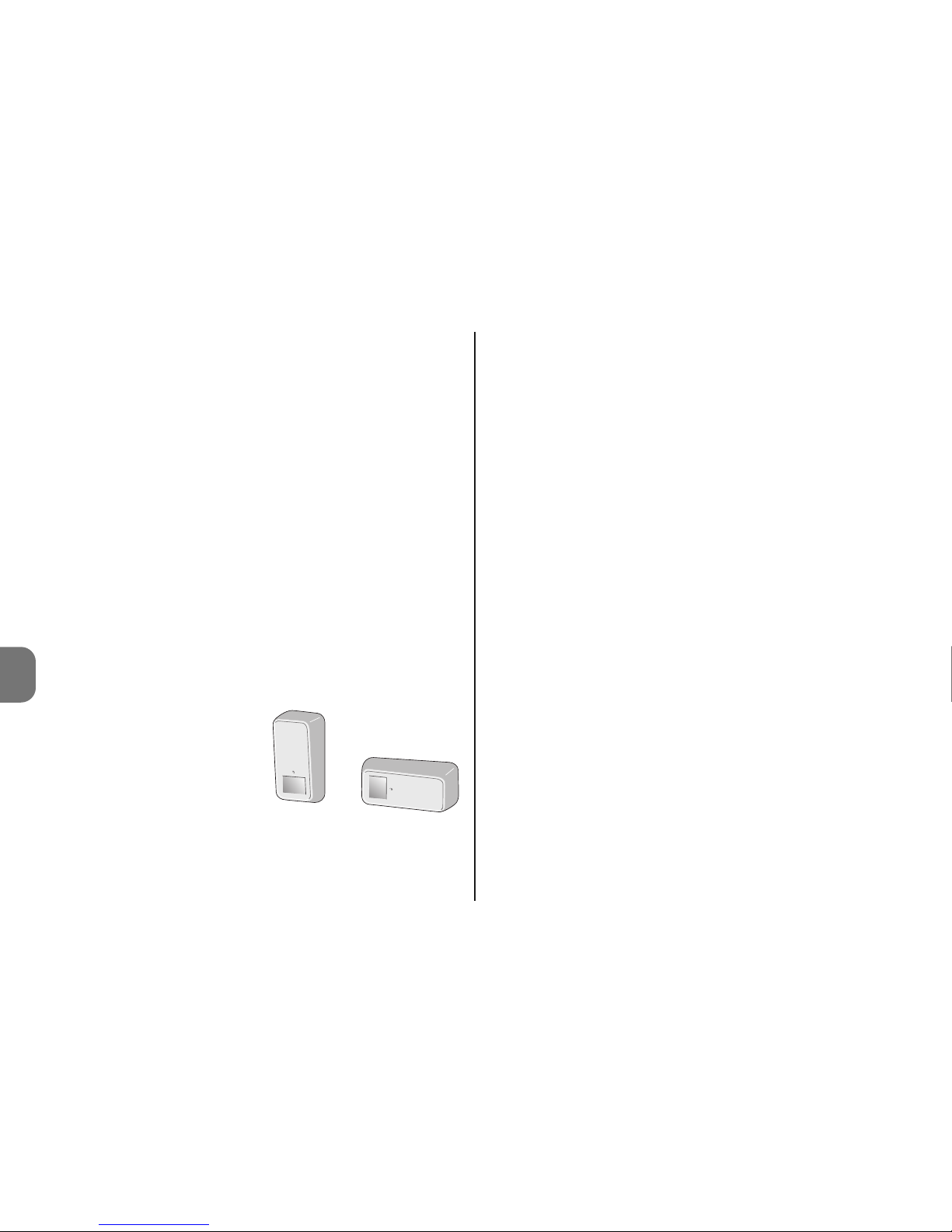
• Sorgfältig den zu schützenden Bereich prüfen; im Zweifelsfall vor der endgültigen Befestigung das Produkt provisorisch befestigen und die Prü fungen und eventuell no twendigen Einstellungen vornehmen.
• Die besondere Form der Linse des Infrarotsensors bildet
einen empfindlichen “Vorhangbereich”. Wenn das Erfassungsgerät vertikal angebracht ist, ist der empfindliche Bereich horizontal (pa rallel zum Boden); wenn das
Erfassungsgerät dagegen
horizontal ist, ist der empfindliche Bereich vertikal
(“Vorhangschutz” mit Bar riereeffekt).
Es ist wichtig, diese Aspekte aufgrund des zu schützenden
Bereichs sorgfältig auch aufgrund einer eventuellen Unempfindlichkeit gegenüber Tieren und je nach Risiko eines
schnellen Durchschreitens des Bereichs zu bewerten.
• Wenn das Produkt winklig installiert werden soll, muss das
ausrichtbare Gelenk Mod. HSA3 verwendet werden (zu sätzliches Zubehörteil). Achtung! - Wenn das Gelenkteil
verwendet wird, geht teilweise der Entfernungsschutz verloren, da das Magnet auf der Befestigung verbleibt. Wenn
der Magnet nicht verwendet wird, den Schutz ausschließen, indem der dip switch 5 auf ON gestellt wird.
01. Die Position der Befestigung entscheiden und prüfen, ob
sie mit dem Gesamtmaß des Erfassungsgerät übereinstimmt: Es muss möglich sein, den Aushakhebel zu er reichen (Abb. 3) und der Platz vorhanden sein, um das
Erfassungsgerät aus- und einzuhaken.
02. A – Wandbefestigung: Zwei Bohrungen für die Befes-
tigungsdübel und eine Bohrung für das Magnet ausführen, das zum Schutz gegen eine Entfernung dient. Dann
die Befestigung mit den hierfür vorgesehenen Dübeln
befestigen (Abb. 4-A);
02.B – Winkelbefestigung mit Gelenk Mod. HSA3:
Das Gelenk an die Wand befestigen (siehe diesbezügliche Gebrauchsanleitung) und dann den Bügel an das
Gelenk befestigen (Abb. 4-B);
03. Den Behälter öffnen, indem die 4 hinteren Schrauben
gelockert werden (Abb. 5);
04. Die Steuerung für die Erlernung von HSDOM21 vorberei-
ten (siehe Gebrauchsanleitung der Steuerung);
05. Das Batteriefach wie in Abb. 6 gezeigt öffnen und die
Isolierlasche abziehen, die die Batterien getrennt hält:
HSDOM21 gibt zwei Serien von jeweils drei Beeps ab
und programmiert sich über die Selbsterlernung ; diese
wird von 1 Beep der Steuerung bestätigt (4 Beeps zeigen an, dass die Vorrichtung schon programmiert ist).
06. Die Programmierung der Dip Switchs ausführen (Abb. 7)
vertikal
horizontal
Page 29
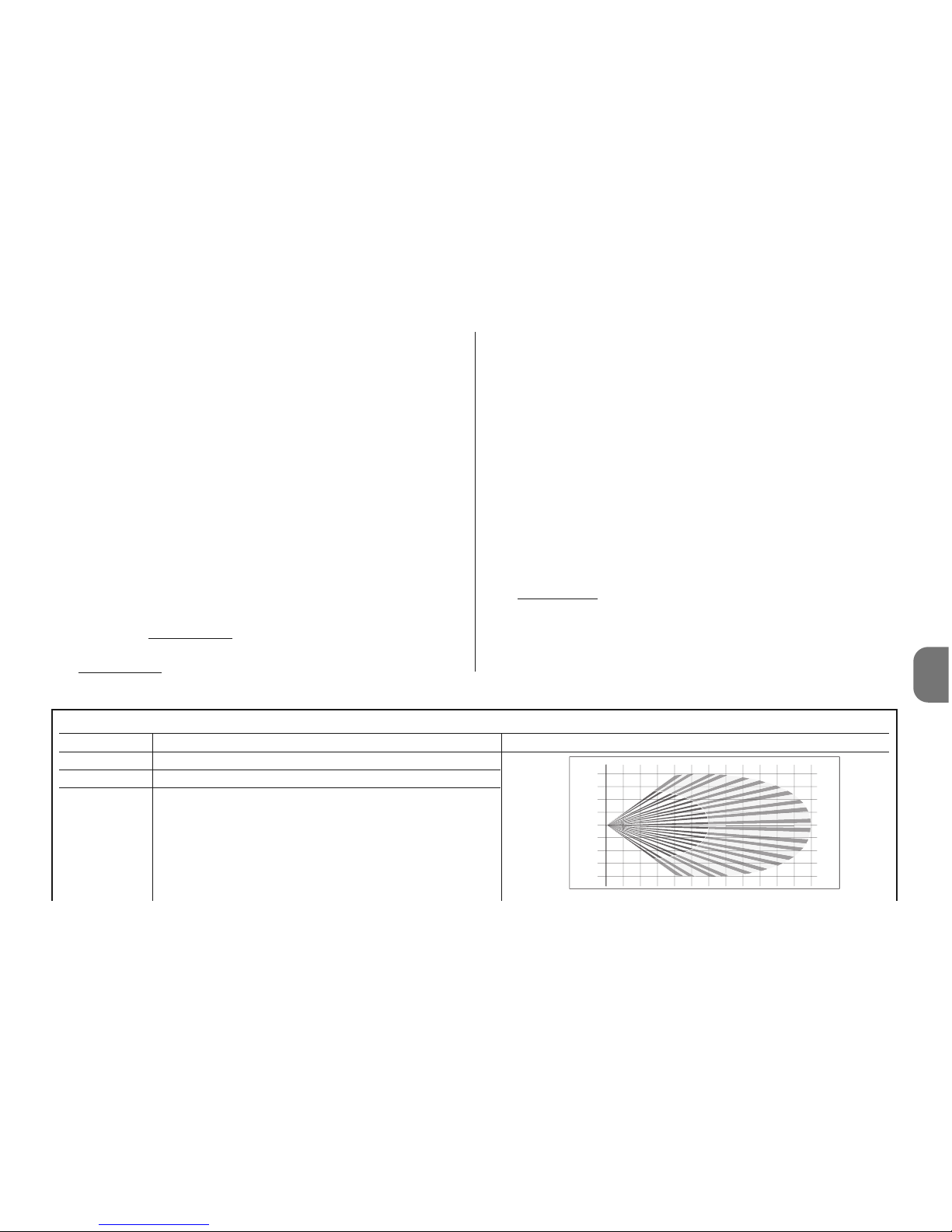
Tabelle 1
Dip Switch Funktion Anmerkungen
Dip 1 Nicht benützt
Dip 2 = OFF Empfindlicher Bereich Infrarotsensor bis zu 6 m
Dip 2 = ON Empfindlicher Bereich Infrarotsensor bis zu 12 m
123456789101112
0
1
2
3
4
4
3
2
1
m
m
DE
sowie die Einstellung der Trimmer (Abb. 7) in Bezug auf
Kap. 3 – Programmierung vornehmen; Dann den “Funk-
tionstest” ausführen, siehe Abschnitt 3.1.
07. Den Behälter wieder schließen (Abb. 8) und HSDOM21
in seine Befestigung einhaken (Abb. 9).
3 - PROGRAMMIERUNG
HSDOM21 verfügt über 5 “dip-switchs” (Abb. 7), die
ermöglichen, einige Betriebsparameter und 2 “Einstelltrimmer” zu programmieren (PT1 und PT2 - Abb. 7): Siehe
Tabelle 1 und Tabelle 2.
3.1 - Programmierungsverfahren und “Funktions-
test”
01. Zuerst wird das Infrarot-Erfassungsgerät mit 1 Impuls pro
Alarm programmiert: Dip-switch 3 = OFF (Tabelle 1).
02. Dann die „Empfindlichkeit“ des Infrarot-Erfassungsgeräts PIR programmieren: Dip-switch 2-1 mit dem not-
wendigen Mindestwert
(Tabelle 1).
03. Den Wert der „Verzögerung nach dem Einbruch“ auf den
Mindestwert
stellen: Trimmer PT2 (Abb. 7).
04. Den Wert der Empfindlichkeit des Mikrowellenerfassungsgerät einstellen (Trimmer PT1 - Abb. 7)
05. Die Abdeckung des geschützten Bereichs prüfen: Kurze
Bewegung innerhalb des Bereichs ausführen und die
durch die Led abgegebenen Anzeigen kontrollieren.
Wenn notwendig, den Empfindlichkeitswert einstellen.
Achtung! – Die Linse des Infrarotsensor ist fest mit dem
Deckel verbunden, somit müssen die Erfassungsversuche bei geschlossenem Gerät ausgeführt werden.
06. Nachdem die Empfindlichkeit eingestellt wurde und zur
Reduzierung der Möglichkeit, dass falsche Alarme auftreten, empfehlen wir die Einstellung des dip-switch 3 =
ON (2 Impulse pro Alarm).
07. Den Wert der „Verzögerung nach dem Einbruch“ auf den
Höchstwert
stellen: Trimmer PT2 (Abb. 7), in Überein-
stimmung mit den Erfassungsanforderungen.
08. Nach der Funktionsprüfung empfehlen wir, den dip-
switch 4 = ON zu stellen, um die Anzeige der Led aus-
zuschalten.
Deutsch - 3
Page 30
4 - Deutsch
DE
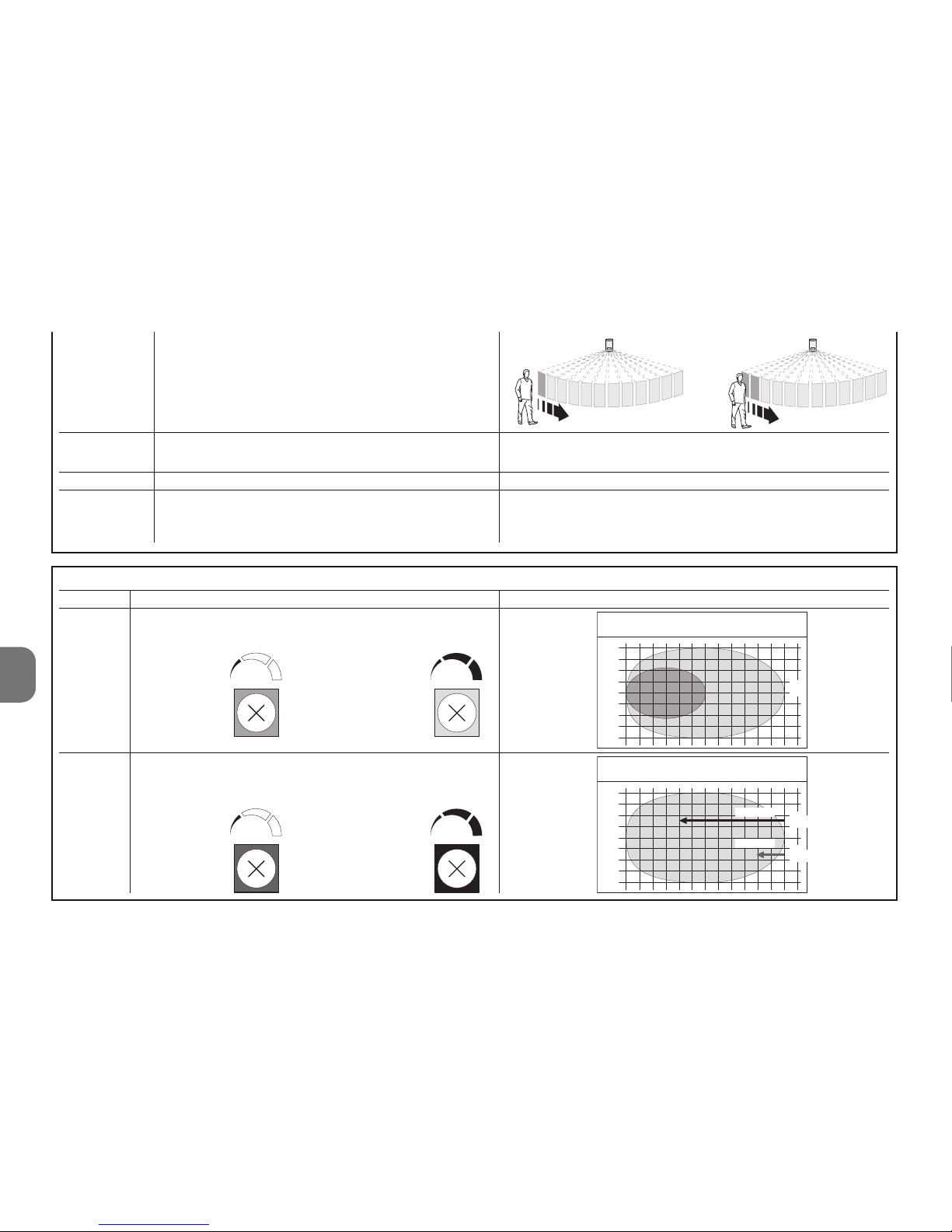
Tabelle 2
Trimmer Funktion Anmerkungen
PT1 Einstellung Bereich Mikrowellensensor
von 6 auf 12 m
PT2 Verzögerung nach Eindringen in den
empfindlichen Bereich vor dem Alarm
1234 56 78 9101112
0
1
2
3
4
4
3
2
1
0
1
2
3
4
4
3
2
1
2,5 sec.
0,25 sec.
m
m
Höchstwert
Mindestwert
Reichweite
m
Verzögerung
Mindestwert Höchstwert
Mindestwert Höchstwert
Dip 3 = OFF Impulszahl Infrarot pro Alarm = 1
Dip 3 = ON Impulszahl Infrarot pro Alarm = 2
Dip 4 = OFF Aktive Anzeigeleds
Dip 4 = ON Abgeschaltete Anzeigeleds
Dip 5 Nicht benützt
Dip 6 = OFF Temperaturausgleich deaktiviert
Dip 6 = ON Temperaturausgleich aktiviert
Achtung! – Die Anzeige der Leds ruft einen höheren Verbrauch der Batterien hervor.
Ruft die automatische Erhöhung der Empfindlichkeit des
PIR hervor, wenn die Umgebungstemperatur über 30°C
beträgt. Diese Funktion nicht sinnlos aktivieren.
Page 31
DE
Deutsch - 5
LED Funktion
Grün Erfassung durch Infrarotsensor (PIR = OK)
Orange Einbruchsverzögerung erfolgt (MW = ?)
Rot Einbruchalarm (PIR+MW = OK)
Buzzer Funktion
1 Beep Alarmanzeige (Einbruch, Manipulierung …)
3+3 Beeps Programmierung des Sensors (Einsetzen der Batterien)
5 Beeps Anzeige leere Batterien
4 - AUSTAUSCH DER BATTERIEN
Achtung! - Auf keinen Fall Batterien unterschiedlicher Art
entgegen der Vorschrift verwenden. Die Batterien müssen
gemeinsam ausgetauscht werden (mit neuen Batterien).
Keine Batterien unterschiedlicher Marken oder Modelle
mischen. Keine aufladbaren Batterien verwenden.
Achtung! - Vor dem Aushaken des Erfassungsgeräts aus
der Halterung muss die Steuerung auf “TEST STEUERUNG” gestellt werden, um grundlose Manipulierungsmeldungen zu vermeiden.
01. Zur Aushakung des Erfassungsgeräts aus der Halterung
wird auf den Einhakhebel gedrückt (Abb. 3).
02. Das Erfassungsgerät zirka 5 mm nach oben schieben
und dann von der Halterung entfernen (Abb. 3).
03. Den Behälter öffnen, indem die 4 hinteren Schrauben
gelockert werden (Abb. 5).
04. Das Batteriefach wie in Abb. 6 gezeigt öffnen und die Bat-
terien ersetzen. Die angegebene Polarität einhalten.
05. Das Erfassungsgerät wieder schließen und die 4 hinteren
Schrauben festziehen (Abb. 8) und HSDOM21 in seine
Befestigung einhaken (Abb. 9).
5 - ENTSORGUNG DER BATTERIEN
Achtung! - Die Batterien in den Vorrichtungen dieses Alarmsystems enthalten auch im leeren Zustand umweltver-
3.2 - Meldungen
HSDOM21 verfügt über 1 Led mit 3 1 Farben und einen
Summer, der hörbare Signale abgibt.
Das Infraroterfassungsgerät ist immer aktiv und im Falle einer
Erfassung eines Eindringlings (grüne Led erleuchtet) wird
sofort das Erfassungsgerät via Mikrowelle (rote Led erleuchtet) aktiviert; wenn auch dieses das Vorhandensein eines
sich bewegenden Körpers bestätigt, wird der Alarmzustand
generiert (rote Led erleuchtet).
Die Anzeige der leeren Batterien erfolgt mit einer Meldung
15-30 Tage vor dem vollständigen Entleeren. Es ist auf jeden
Fall vorzuziehen, diese so schnell wie möglich zu ersetzen.
Wenn die Batterien teilweise leer sind, könnte die korrekte
Alarmanzeige nicht erfolgen.
Page 32
DE
6 - Deutsch
CE-KONFORMITÄTSERKLÄRUNG
Anmerkung - Der Inhalt dieser Erklärung entspricht den Erklärungen der letzten verfügbaren Revision vor dem Druck dieses Handbuchs des offiziellen Dokuments das im Sitz Nice Spa hinterlegt
ist. Dieser Text wurde aus Herausgebergründen angepasst.
Nummer: 331/HSDOM21 Revision: 0
Der Unterzeichnende Luigi Paro erklärt als Geschäftsführer unter seiner eige-
nen Verantwortung, dass das Produkt:
Herstellername: NICE s.p.a.
Adresse: Via Pezza Alta 13, Z.I. Rustignè, 31046 Oderzo (TV) Italien
Typ: Infrarot-Erfassungsgerät mit doppelter Funktechnologie.
Modelle: HSDOM21
Zubehör:
mit den wichtigsten Anforderungen des Artikels 3 folgender europäischer
Richtlinie konform ist, was den Einsatzzweck der Produkte betrifft:
• 1999/5/CE: RICHTLINIE 1999/5/CE DES EUROPAPARLAMENTS UND DES
RATES vom 9. März 1999, was die Funkapparaturen und Terminals für Fernmeldewesen und die gegenseitige Anerkennung ihrer Konformität betrifft.
Gemäß der folgenden harmonisierten Normen:
Schutz der Gesundheit: EN 50371:2002; elektrische Sicherheit: EN 609501:2006; elektromagnetische Kompatibilität: EN 301 489-1V1.8.1:2008; EN
301 489-3V1.4.1:2002; Funkspektrum: EN 300220-2V2.1.2:2007, EN3004402V1.3.1.:2009
In Übereinstimmung mit den Richtlinien 1999/5/CE (Anlage V) entspricht das
Produkt der Klasse 1 und ist wie folgt markiert:
Außerdem ist das Produkt konform mit den Vorschriften der folgenden EURichtlinien:
• 2004/108/EWG (ehemalige Richtlinie 89/336/EWG) RICHTLINIE 2004/108/
EG DES EUROPÄISCHEN PARLAMENTS UND DES RATES vom 15. Dezember 2004 zur Angleichung der Rechtsvorschriften der Mitgliedstaaten über die
elektromagnetische Verträglichkeit und zur Aufhebung der Richtlinie 89/336/EWG
Gemäß den folgenden übereinstimmenden Normen:
EN 50130-4:1995+A1:1998+A2:2003
Oderzo, 20. November 2009
Ing. Luigi Paro (Geschäftsführer)
0682
schmutzende Substanzen und dürfen somit nicht in den normalen Hausmüll geworfen werden. Sie müssen nach den
örtlich gültigen Vorschriften differenziert entsorgt werden.
6 - TECHNISCHE EIGENSCHAFTEN
HINWEISE: • Alle angegebenen technischen Merkmale beziehen sich
auf eine Temperatur von 20°C (± 5°C). • Nice S.p.a. behält sich das
Recht vor, jederzeit als nötig betrachtete Änderungen am Produkt vorzunehmen, wobei Funktionalitäten und Einsatzzweck beibehalten werden.
■ Typologie: Volumetrisches Erfassungsgerät mit doppelter
Infrarottechnologie (PIR) und Mikrowellenradar (MW), für
Anwendungen im Außenbereich. Schutz gegen Öffnung und
Entfernung ■ Speisung: 4,5V mit 3 Batterien, 1,5V Typ AA
oder ähnliches ■ Aufgenommener Strom: 70 µA in Ruhe-
stellung - 40 mA bei Übertragung ■ Autonomie: Ca. 2 Jahre (bei Dip 4 = ON), mit Signalisierung der leeren Batterie ■
Funkübertragung: Digitale Mitteilung, in doppelter Frequenz
“DualBand” (433 und 868MHz) quarzkontrolliert; werkseitig
vorcodierte selbst erlernende Vorrichtungen ■ Funkreich-
weite: 100 m auf freiem Feld ohne Störungen, zirka 20 m in
Gebäuden ■ Isolierung: Klasse III ■ Mikrowellenfrequenz:
9,9 GHz ■ Höchstleistung Mikrowelle: < 20 mW (ent-
spricht EN 50371); für eine durchgehende Höchstzeit von 5s
n Betriebstemperatur ■ Schutzgrad des Behälters: IP 65 ■
Betriebstemperatur: -25°C bis +55 °C ■ Anwendung in
Umgebungen der Umgebungsklasse: II ■ Montage: An
der Wand ■ Abmessungen (mm): 158 x 83 50 mm ■ Ge -
wicht: 0,37 Kg
Page 33

Instrukcje oryginalne
POLSKI
Polski - 1
PL
SPECYFICZNE ZALECENIA
• Zainstaluj urządzenie w pozycji trudno dostępnej celem
uniknięcia zamierzonego jego uszkodzenia.
• Nie instaluj go w pobliżu możliwych turbulencji ciepłego lub
zimnego powietrza oraz tam, gdzie przebywają zwierzęta
stałocieplne (fig 1).
• Jeżeli w przeznaczonym do zabezpieczenia otoczeniu często przebywają zwierzęta domowe, należy umieścić czujkę
objętościową HSDOM21 na odpowiedniej wysokości i
usta wić ją prawidłowo w taki sposób, aby strefa czułości
znajdowała się na wysokości 50-70 cm od ziemi, jak pokazano na rys. 2 (przekrój pionowy); ewentualnie jest również
możliwe zredukowanie wartości czułości czujnika.
• Nie instaluj czujki HSDOM21 w miejscach narażonych na
bezpośrednie działanie promieni słonecznych, aby zapobiec wewnętrznemu przegrzewaniu się urządzenia; słońce
nie powoduje szkód dla urządzenia, może jednakże zmieniać czułość czujki podczerwieni, fałszując w ten sposób
skutki kompensacji temperatury otoczenia, która różni się
od temperatury występującej wewnątrz urządzenia.
• Nie używaj czujki HSDOM21 do zabezpieczania stref znajdujących się na zewnątrz budynków i narażonych na niepogodę, na przykład śnieg lub mocno padający deszcz; mogą
one powodować powstawanie niewłaściwych alarmów.
HSDOM21 jest czujką objętościową z podwójną technologią,
podczerwień i radar mikrofalowy. Jest ona przystosowana do
obejmowania swoim zasięgiem obszaru o wymiarach do 12
m, widzianego pod kątem 90°; dysponuje regulacją czułości,
typu alarmu (natychmiastowy lub przy drugim impulsie) oraz
zabezpieczeniem przed otwieraniem i zdejmowaniem ze ściany. Każde inne zastosowanie jest niewłaściwe i zabronio-
ne! Firma Nice nie odpowiada za szkody wynikające z niewłaściwego używania urządzenia, odmiennego od przewidzianego w tej instrukcji.
1 - FUNKCJONOWANIE
HSDOM21 jest czujką objętościową z podwójną technologią
(PIR = Pasywny czujnik podczerwieni + MW = Mikrofalowa
czujka Dopplera), zaprojektowaną do wykrywania osób przemieszczających się wewnątrz obszaru zabezpieczonego. Te
dwie różne technologie umożliwiają zredukowanie możliwości występowania niewłaściwych alarmów, wywoływanych
przez czynniki środowiskowe; aby zagwarantować optymalne funkcjonowanie należy prawidłowo zamontować i wyregulować urządzenie. W najbardziej ekstremalnych przypadkach, aby dodatkowo zredukować obecność niewłaściwych
alarmów, istnieje możliwość zainstalowania na tym samym
obszarze dwóch czujek, zamontowanych przeciwlegle do
siebie oraz zaprogramowanie centrali na funkcję “AND”
(przeczytaj instrukcje obsługi centrali). Zastosowanie regulowanego przegubu mod. HSA3 (opcja), umożliwia prawidłowe
umiejscowienie i ustawienie urządzenia, w szczególności
podczas montażu kątowego (patrz rozdz. 2 – Montaż).
Czujka HSDOM21 funkcjonuje z zastosowaniem 3 baterii
alkalicznych typu AA; nie dysponuje żadnym połączeniem
elektrycznym z zewnątrz, a w przypadku wykrycia włamania
przekazuje alarm drogą radiową do centrali.
Czujka podczerwieni w urządzeniu jest zawsze aktywna i w
przypadku wykrycia włamania (świecąca się czerwona dioda) natychmiast uaktywnia czujkę mikrofalową, (świecąca się
pomarańczowa dioda); jeżeli również i ona potwierdza obecność obiektu znajdującego się w ruchu, stwarzany jest stan
Page 34
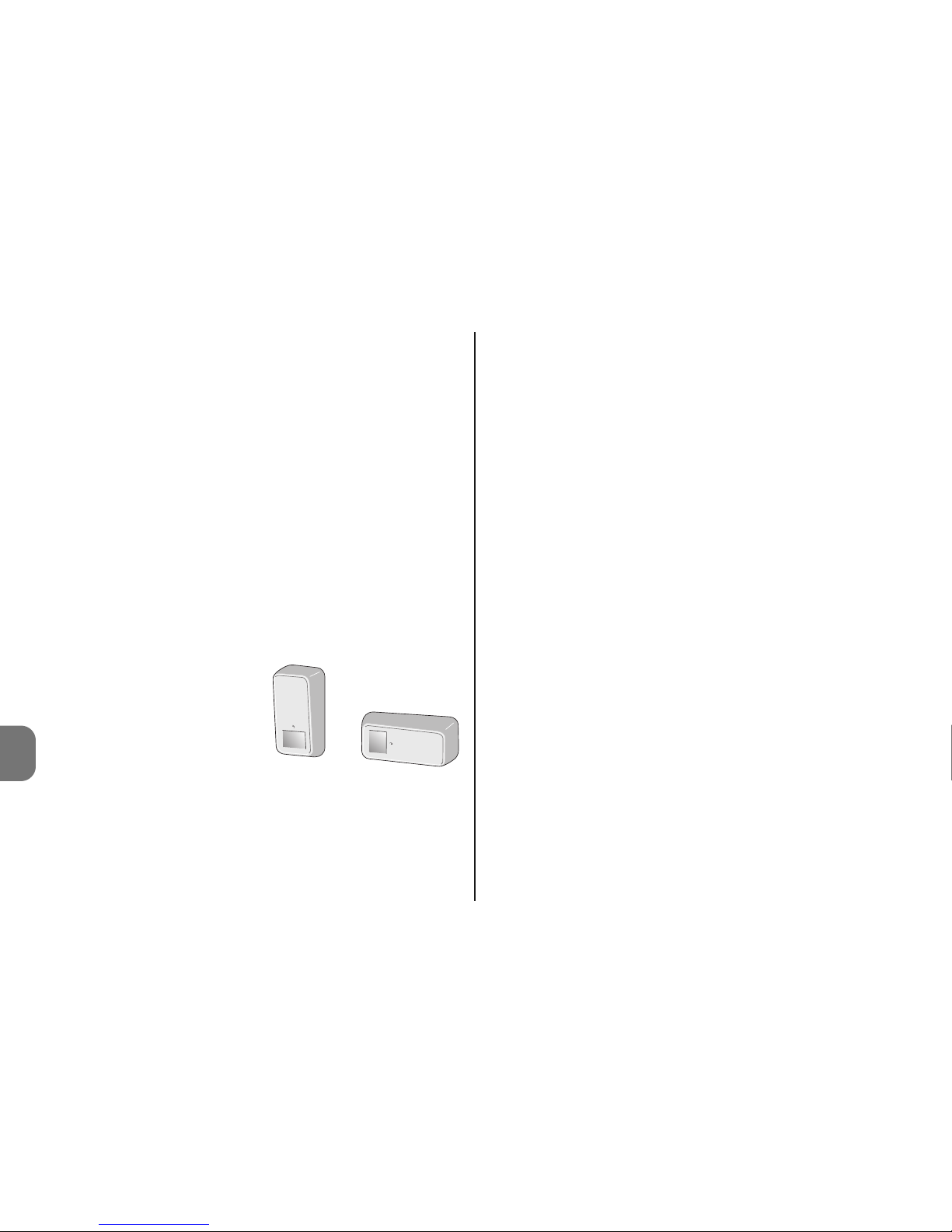
2 - Polski
PL
alarmu (świeci się czerwona dioda).
Uwaga! – W przypadku zdjętej górnej pokrywy czujki HSDOM21
system pozostaje aktywny.
Czujka dysponuje zabezpieczeniem przed jej zdejmowaniem i
otwieraniem.
HSDOM21 przekazuje do centrali sygnał kontrolny co około 40
minut. Jest on niezbędny dla “funkcji nadzorowania” w centrali.
2 - MONTAŻ
Zalecenia
• Wyznacz położenie i wysokość, na której czujka HSDOM21
zostanie przymocowana, w zależności od obszaru zabezpieczonego, który zamierzasz uzyskać: odwołaj się do rys. 2.
• Uważnie sprawdź kształt zabezpieczanej strefy, w przypadku
wątpliwości przed ostatecznym przymocowaniem czujki
zaleca się przymocowanie próbne i wykonanie odpowiednich
testów oraz ewentualnych niezbędnych regulacji.
• Szczególny kształt soczewki czujnika podczerwieni stwarza strefę czułości typu “kurtyna”. Jeżeli czujka jest ustawiona pionowo, strefa czułości jest pozioma (równoległa do podłoża); jeżeli natomiast jest ona ustawiona
poziomo, w tym przypadku
strefa czułości jest pionowa
(zabezpieczenie kurtynowe
z efektem bariery).
Ważne jest, aby dokładna
ocena tych aspektów została przeprowadzona w zależności od obszaru zabezpieczonego, ewentualnej nieczułości
na zwierzęta oraz zagrożenia szybkiego przemieszczania
się na tym obszarze.
• Jeżeli zamierzasz zainstalować urządzenie pod kątem,
musisz zastosować regulowany przegub mod. HSA3
(opcja): Uwaga! – W przypadku zastosowania przegubu
zmniejsza się częściowo zabezpieczenie przed usunięciem
urządzenia, ponieważ magnes pozostaje na uchwycie. W
przypadku, kiedy magnes nie zostanie zastosowany należy
wykluczyć zabezpieczenie, przełączając przełącznik dip-
switch 5 = ON
01. Wybierz położenie, w którym uchwyt zostanie przymo-
cowany, sprawdzając, czy jest ono zgodne z całkowitymi
wymiarami czujki: musi być możliwy swobodny dostęp
do dźwigienki umożliwiającej zdejmowanie czujki (rys.
3), należy również dysponować przestrzenią umożliwiającą jej zdejmowanie i zakładanie.
02. A – Przymocowanie do ściany: wywierć dwa otwory
umożliwiające włożenie kołków mocujących oraz jeden
otwór przeznaczony dla magnesu, który służy do zabezpieczenia urządzenia “przed zdjęciem”. Następnie przymocuj uchwyt specjalnymi kołkami (rys. 4-A);
02. B – Przymocowanie kątowe z zastosowaniem pr zegubu mod. HSA3: przymocuj przegub do ściany (prze-
czytaj odpowiednią instrukcję obsługi), następnie przy mocuj uchwyt do przegubu, jak pokazano na (rys. 4-B);
03. Otwórz obudowę poluzowując 4 tylne śruby (rys. 5);
04. Przygotuj centralę do autoprogramowania czujki HSDOM21
(przeczytaj instrukcję obsługi centrali);
05. Otwórz komorę baterii, jak pokazano na rys. 6 i wyjmij
pasek izolujący, dzięki któremu baterie pozostają odłączone: Czujka HSDOM21 wykona dwie serie po 3 sy gnały dźwiękowe każda i rozpocznie programowanie w
trybie autoodczytu; jego zakończenie zostanie następnie
potwierdzone przez jeden sygnał dźwiękowy wykonany
przez centralę, (4 sygnały dźwiękowe wskazują, że urządzenie zostało już wcześniej zaprogramowane).
06. Zaprogramuj przełączniki typu dip switch (rys. 7) i prze-
pionowy poziomy
Page 35
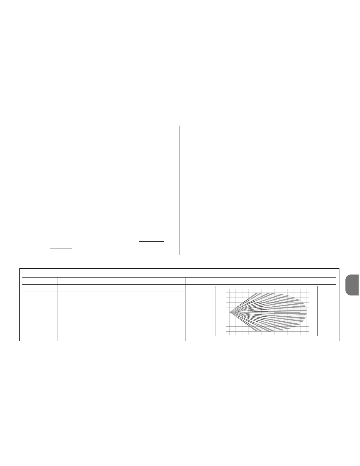
Tabela 1
Dip Switch Funkcja Uwagi
Dip 1 Nieużywany
Dip 2 = OFF Strefa czułości czujnika podczerwieni do 6 m
Dip 2 = ON Strefa czułości czujnika podczerwieni do 12 m
123456789101112
0
1
2
3
4
4
3
2
1
m
m
PL
prowadź regulację trymerów (rys. 7) nawiązując do
rozdz. 3 - Programowanie; następnie wykonaj “Test”
funkcjonowania, patrz paragraf 3.1.
07. Zamknij obudowę (rys. 8) i załóż czujkę HSDOM21 na
odpowiedni uchwyt mocujący (rys. 9).
3 - PROGRAMOWANIE
Czujka HSDOM21 dysponuje pięcioma przełącznikami typu
“dip-switch” (rys. 7), które umożliwiają programowanie róż-
nych parametrów funkcjonowania oraz dwoma “trymerami”
regulacyjnymi (PT1 i PT2 - rys. 7): patrz Tabela 1 i Tabela 2.
3.1 - Procedura programowania oraz “Test” funkcjonowania
01. Po pierwsze zaprogramuj czujkę podczerwieni na 1
impuls dla alarmu: dip-switch 3 = OFF (Tabela 1).
02. Następnie zaprogramuj “czułość” czujki podczerwieni
PIR: przełącz przełącznik dip-switch 2 na najniższą
nie-
zbędną wartość
(Tabela 1).
03. Wyreguluj na najniższą
wartość “opóźnienie po włama-
niu”: trymer PT2 (rys. 7).
04. Wyreguluj wartość czułości czujki mikrofalowej (trymer
PT1 - rys. 7).
05. Sprawdź zasięg obszaru zabezpieczonego: wykonaj
kró tkie przemieszczenia wewnątrz tego obszaru i spra wdź sygnalizacje wykonywane przez diodę. Jeżeli to
konieczne wyreguluj wartość czułości. Uwaga! – Soc zewka czujnika podczerwieni jest przymocowana na stałe na pokrywie, w związku z tym próby wykrywania
muszą być wykonywane przy zamkniętej pokrywie.
06. Po wyregulowaniu czułości, aby zredukować możliwość
wystąpienia niewłaściwych alarmów, zaleca się przestawić
przełącznik dip-switch 3 = ON (2 impulsy dla alarmu).
07. Z tego samego powodu wyreguluj na najwyższą
wartość
“opóźnienie po włamaniu”: trymer PT2 (rys. 7), zgodnie
z wymogami wykrywania.
08. Po zakończeniu weryfikacji funkcjonowania zaleca się
przełączyć przełącznik dip-switch 4 = ON, aby wyłączyć sygnalizację diody.
Polski - 3
Page 36
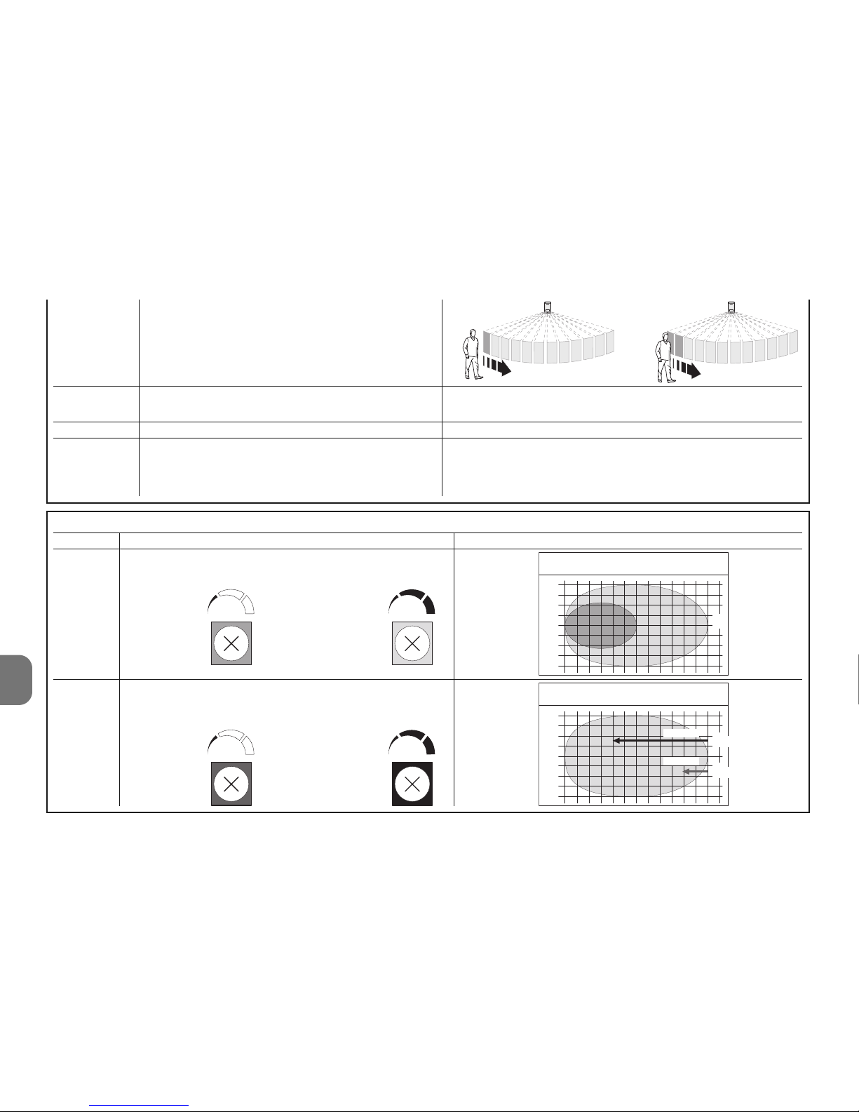
4 - Polski
PL
Tabela 2
Trymer Funkcja Uwagi
PT1 Regulacja strefy czujnika mikrofali
od 6 do 12 m
PT2 Opóźnienie po włamaniu do strefy
nadzorowanej przed włączeniem alarmu
1234 56 78 9101112
0
1
2
3
4
4
3
2
1
0
1
2
3
4
4
3
2
1
2,5 sec.
0,25 sec.
m
m
maksymalne
minimalne
Zasięg
m
Zasięg
minimalne maksymalne
minimalne maksymalne
Dip 3 = OFF Ilość impulsów podczerwieni dla alarmu = 1
Dip 3 = ON Ilość impulsów podczerwieni dla alarmu = 2
Dip 4 = OFF Diody sygnalizujące włączone
Dip 4 = ON Diody sygnalizujące wyłączone
Dip 5 Nieużywany
Dip 6 = OFF Kompensacja temperatury wyłączona
Dip 6 = ON Kompensacja temperatury włączona
Uwaga! – Sygnalizacja diod powoduje większe zużycie
baterii.
Powoduje ona automatyczny wzrost czułości pasywnego czujnika podczerwieni (PIR) w przypadku, kiedy temperatura otoczenia przekracza 30°C. Nie włączaj tej funkcji, jeśli nie istnieje taka potrzeba.
Page 37
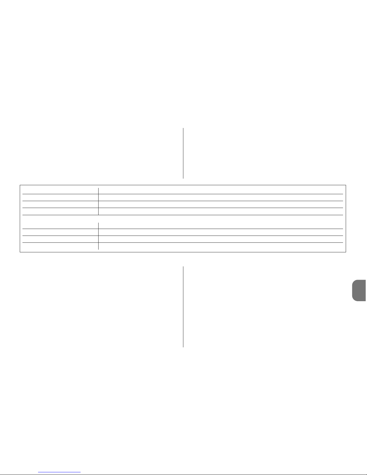
PL
Polski - 5
DIODA Funkcja
Zielona Wykrywanie przez czujnik podczerwieni (PIR = OK)
Pomarańczowa Opóźnienie włamanie w toku ( MW = ?)
Czerwona Alarm włamaniowy (PIR+MW = OK)
Sygnalizator akustyczny Funkcja
1 Sygnał dźwiękowy Sygnalizacja alarmu (włamanie, sabotaż, itp…)
3+3 Sygnały dźwiękowe Programowanie czujnika (włożenie baterii)
5 Sygnałów dźwiękowych Sygnalizacja rozładowanych baterii
4 - WYMIANA BATERII
Uwaga! – Nie używaj z żadnego powodu baterii odmien-
nych od zalecanego typu. Baterie muszą być wymieniane
wszystkie razem (na nowe). Nie mieszaj ze sobą baterii innej
marki lub modelu. Nie używaj baterii doładowywanych.
Uwaga! – Przed zdjęciem czujki z uchwytu mocującego
należy przełączyć centralę na tryb “TEST CENTRALI”,
aby zapobiec spowodowaniu niepotrzebnych sygnalizacji sabotażowych.
01. Aby zdjąć czujkę z uchwytu mocującego należy naci-
snąć na specjalną dźwigienkę mocującą (rys. 3).
02. Przesuń czujkę o około 5 mm do góry i odsuń ją od
uchwytu mocującego (rys. 3).
03. Otwórz obudowę poluzowując 4 tylne śruby (rys. 5).
04. Otwórz komorę baterii, jak pokazano na rys. 6 i wymień
baterie. Przestrzegaj zalecanej biegunowości.
05. Zamknij czujkę dokręcając 4 tylne śruby (rys. 8) i załóż
HSDOM21 na odpowiedni uchwyt mocujący (rys. 9).
5 - UTYLIZACJA BATERII I AKUMULATORÓW
Uwaga! – Baterie i akumulatory znajdujące się w urządzeniach, które składają się na ten system alarmowy, również,
jeśli są rozładowane zawierają substancje zanieczyszczające, a w związku z tym nie mogą być wyrzucane razem ze
3.2 - Sygnalizacje
Czujka HSDOM21 dysponuje 1 trójkolorową diodą oraz
sygnalizatorem akustycznym, który generuje sygnalizacje
akustyczne.
Czujka podczerwieni jest zawsze aktywna i w przypadku
wykrycia włamania (świecąca się czerwona dioda) natychmiast uaktywnia czujkę mikrofalową, (świecąca się pomarańczowa dioda); jeżeli również i ona potwierdzi obecność
obiektu znajdującego się w ruchu, generowany jest stan alarmu (świeci się czerwona dioda).
Sygnalizacja rozładowanych baterii następuje z wyprzedzeniem 15-30 dni w stosunku do całkowitego ich wyczerpania.
W każdym razie preferowana jest ich jak najszybsza wymiana. W przypadku, kiedy baterie są częściowo rozładowane
może nie nastąpić prawidłowe zasygnalizowanie alarmu.
Page 38
PL
6 - Polski
DEKLARACJA ZGODNOŚCI CE
Uwaga - Zawartość niniejszej deklaracji odpowiada oświadczeniom znajdującym się w dokumencie urzędowym, złożonym w siedzibie firmy Nice S.p.a., a w szczególności w ostatniej korekcie
dostępnej przed wydrukowaniem tej instrukcji. Tekst w niej zawarty został dostosowany w celach
wydawniczych.
Numer: 331/HSDOM21 Wydanie: 0
Niżej podpisany Luigi Paro, w charakterze Członka Zarządu Spółki oświadcza
na własną odpowiedzialność, że urządzenie:
Nazwa producenta: NICE s.p.a.
Adres: Via Pezza Alta 13, Z.I. Rustignè, 31046 Oderzo (TV),
Włochy
Typ: Czujka radiowa podczerwieni z podwójną technologią
Modele: HSDOM21
Akcesoria:
Jest zgodne z podstawowymi wymogami artykułu 3 niżej zacytowanej dyrektywy europejskiej, podczas użytku, do którego te urządzenia są przeznaczone:
• 1999/5/WE DYREKTYWA 1999/5/WE PARLAMENTU EUROPEJSKIEGO I
RADY z dnia 9 marca 1999 roku w sprawie urządzeń radiowych i końcowych
urządzeń telekomunikacyjnych oraz wzajemnego uznawania ich zgodności
Zgodnie z następującymi normami zharmonizowanymi
ochrona zdrowia: EN 50371:2002; bezpieczeństwo elektryczne: EN 609501:2006; kompatybilność elektromagnetyczna: EN 301 489-1V1.8.1:2008; EN
301 489-3V1.4.1:2002 ; widma radiowe: EN 300220-2V2.1.2:2007, EN3004402V1.3.1.:2009
Zgodnie z dyrektywą 1999/5/WE (załącznik V), produkt ten został zaliczony do
klasy 1 i jest oznaczony następującym symbolem:
Ponadto urządzenie jest zgodne z założeniami następujących dyrektyw unijnych:
• 2004/108/EWG (ex dyrektywa 89/336/EWG) DYREKTYWA 2004/108/WE
PARLAMENTU EUROPEJSKIEGO I RADY z dnia 15 grudnia 2004 roku, dotycząca zbliżenia legislacyjnego krajów członkowskich w odniesieniu do kompatybilności elektromagnetycznej, która uchyla dyrektywę 89/336/EWG
Zgodnie z następującymi normami zharmonizowanymi:
EN 50130-4:1995+A1:1998+A2:2003
Oderzo, dnia 20 listopada 2009 roku
Ing. Luigi Paro (Członek Zarządu Spółki)
0682
zwykłymi odpadami. Należy je likwidować stosując metody
‘selektywnej zbiórki odpadów’, przewidziane przez przepisy
obowiązujące na Waszym terytorium.
6 - PARAMETRY TECHNICZNE
Zalecenia: • Wszystkie podane parametry techniczne dotyczą temperatury środowiskowej 20°C (± 5°C). • Firma Nice S.p.a. zastrzega sobie
prawo do wprowadzenia zmian do urządzenia w każdej chwili, kiedy
uzna je za konieczne, zachowując te same funkcje i przeznaczenie.
■ Ty p: czujka objętościowa z podwójną technologią, pod-
czerwień (PIR) i radar mikrofalowy (MW); przeznaczona do
użytku na zewnątrz budynków. Zabezpieczenie przed otwieraniem i wyjmowaniem ■ Zasilanie: 4,5V z zastosowaniem
3 baterii typu AA lub ekwiwalentnych ■ Prąd pobierany: 70
μA w stanie spoczynku - 40 mA podczas transmisji ■
Żywotność baterii: oszacowana na 2 lata (z Dip 4 = ON), z
sygnalizacją rozładowanej baterii ■ Transmisja radiowa:
łączność cyfrowa w dwóch zakresach częstotliwości “DualBand” (433 i 868MHz) sterowana kwarcem; urządzenia
kodowane fabrycznie i zarządzane przez autoprogramowanie ■ Zasięg radiowy: 100 na zewnątrz budynków w przy-
padku niewystępowania zakłóceń; około 20m wewnątrz
budynków ■ Izolacja: klasy III ■ Częstotliwość mikrofali:
9,9 GHz ■ Maksymalna moc mikrofali: < 20 mW (zgodnie
z normą EN 50371); przez maksymalny ciągły czas 5s ■
Stopień zabezpieczenia obudowy: IP 65 ■ Temperatura
funkcjonowania: od -25°C do +55 °C ■ Zastosowanie w
pomieszczeniach klasy środowiskowej: II ■ Montaż:
naścienny ■ Wymiary (mm): 158 x 83 x 50 ■ Waga: 0,37 kg
Page 39

Originele instructies
NEDERLANDS
Nederlands - 1
NL
SPECIALE AANWIJZINGEN
• Installeer het product op een moeilijk bereikbare plaats om
te voorkomen dat het opzettelijk beschadigd kan worden.
• Installeer het product niet op plaatsen waar mogelijke war-
me of koude luchtstromen kunnen optreden en waar zich
warmbloedige dieren bevinden (afb. 1).
• Als er huisdieren in de te beschermen ruimte zijn, is het
noodzakelijk HSDOM21 op de juiste hoogte en in de goede
richting te plaatsen, zodanig dat het gevoeligheidsgebied op
50-70 cm van de grond wordt gehouden, zoals aangegeven op afb. 2 (verticaal aanzicht); het is eventueel ook
mogelijk de gevoeligheidswaarde van de sensor te verlagen.
• Installeer HSDOM21 niet op plaatsen die direct in het zon-
licht liggen, om interne oververhitting te voorkomen; de
zon veroorzaakt geen schade aan het product, maar verandert de gevoeligheid van de infrarooddetector waardoor
de effecten van de compensatie van de omgevingstemperatuur, die anders is dan de interne temperatuur van het
product, niet betrouwbaar meer zijn.
• Gebruik HSDOM21 niet voor het beveiligen van gebieden
buitenshuis die blootgesteld zijn aan weersinvloeden als
bijvoorbeeld sneeuw of slagregen, hierdoor kan het alarm
abusievelijk afgaan.
HSDOM21 is een volumedetector met dubbele technologie,
met infraroodstraling en microgolfradar. De inrichting kan een
gebied met afmetingen tot 12 meter dekken, met een hoekopening van 90°; hij is voorzien van gevoeligheidsregeling,
van regeling van het alarmtype (onmiddellijk of bij de tweede
impuls) en van een beveiliging tegen openen en verwijderen
van de inrichting. Geschikt voor gebruik in overdekte, bui
-
tenshuis liggende ruimtes
. Ieder ander gebruik dient als
oneigenlijk en dus als verboden te worden beschouwd!
Nice is niet aansprakelijk voor schade die het gevolg is
van een oneigenlijk gebruik van het product, anders dan
in deze handleiding is voorzien.
1 - WERKING
HSDOM21 is een volumedetector met dubbele technologie
(PIR = Passive Infra-Red detector + MW = Micro Wave doppler detector), die ontwikkeld is voor het detecteren van de
beweging van personen binnen een beveiligd gebied. Het
gebruik van de twee verschillende technologieën verkleint de
mogelijkheid dat het alarm ten onrechte af gaat als gevolg
van factoren uit de omgeving; voor een optimale werking is
het noodzakelijk dat het product correct wordt geplaatst en
ingesteld. In de meest extreme gevallen is het, om de kans
op onjuiste alarmen nog verder te verkleinen, mogelijk om
twee detectors in hetzelfde gebied te installeren. Deze
detectors moeten tegenover elkaar worden opgesteld en de
besturingseenheid moet op de functie “AND” worden geprogrammeerd (zie de instructiehandleiding van de besturingseenheid). Het gebruik van het verstelbare scharnier mod.
HSA3 (optioneel accessoire) laat een correcte plaatsing en
richting van het product toe, in het bijzonder voor de bevestiging in een hoek (zie hoofdstuk 2 - Installatie).
HSDOM21 werkt met 3 alkalinebatterijen type AA; hij heeft
geen enkele elektrische aansluiting naar buiten toe en in het
geval er een insluiper wordt gedetecteerd, zendt hij het alarm
via een radioverbinding naar de besturingseenheid.
De infrarooddetector in het product is altijd actief en in het
geval er een betreding van het beveiligde gebied wordt gedetecteerd (groene led brandt) wordt onmiddellijk ook de microgolfdetector geactiveerd (oranje led brandt); als ook deze
Page 40
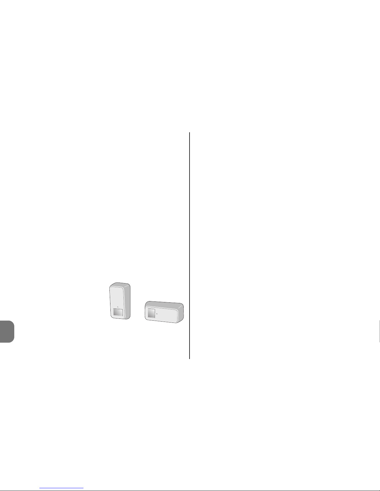
2 - Nederlands
NL
detector het bestaan van een bewegend lichaam bevestigt,
wordt de alarmstatus gegenereerd (rode led brandt).
Let op! – Wanneer het bovendeksel van de HSDOM21
wordt verwijderd, blijft het systeem altijd actief.
De detector is voorzien van beveiligingen tegen verwijderen
en openen.
HSDOM21 stuurt ongeveer om de 40 minuten een levensteken aan de besturingseenheid; dit levensteken is noodzakelijk voor de “supervisiefunctie" op de besturingseenheid.
2 - INSTALLATIE
Aanbevelingen
• Bepaal de bevestigingspositie en -hoogte van de
HSDOM21, afhankelijk van het gebied dat u wilt beveiligen:
zie afb. 2.
• U dient de vorm van het gebied dat u wilt beveiligen nauw-
gezet te bestuderen; in geval van twijfel wordt aangeraden
om, alvorens het product definitief vast te zetten, het provisorisch te bevestigen en tests en eventueel noodzakelijke
instellingen uit te voeren.
• De speciale vorm van de lens van de infraroodsensor creë-
ert een “tentvormig” gevoelig gebied. Als de detector in
verticale stand wordt ge plaatst, is het gevoelige ge bied horizontaal (parallel
aan de grond); als de de tector daarentegen in horizontale stand wordt ge plaatst, is het gevoelige ge bied verticaal (beveiliging in
vorm van een ‘tent’, met het
effect van een barrière).
Het is belangrijk om deze aspecten zorgvuldig te beoordelen, uitgaande van het gebied dat u wilt beveiligen en rekening houdend met de eventuele noodzaak dat de inrichting
ongevoelig is voor huisdieren en met de mogelijkheid dat
iemand het gebied snel doorkruist.
• Als u het product in een hoek wilt installeren, dient u ge bruik te maken van het verstelbare scharnier mod. HSA3
(optioneel accessoire): Let op! – Bij gebruik van het scharnier gaat de beveiliging tegen verwijdering van de inrichting
gedeeltelijk verloren, aangezien de magneet op de beugel
blijft. Als de magneet niet gebruikt wordt, dient u de beveiliging te deactiveren met de instelling dip-switch 5 = ON
01. Bepaal de bevestigingspositie van de beugel en controleer
hierbij of deze compatibel is met de totale ruimte die de
detector in beslag neemt: het moet mogelijk zijn om het
deblokkeerhendeltje te bereiken (afb. 3) en er moet vol-
doende ruimte zijn om de detector los en vast te maken.
02. A – Wandmontage: boor twee gaten voor de bevesti-
gingspluggen en een gat voor de magneet, die dient voor
de beveiliging “tegen verwijdering”. Zet vervolgens de
beugel vast met de hiervoor bestemde pluggen (afb. 4-A);
02. B – Hoekmontage met scharnier mod. HSA3: be -
ve stig het scharnier aan de wand (zie de betreffende
instructiehandleiding) en bevestig vervolgens de beugel
aan het scharnier zoals aangegeven in (afb. 4-B);
03. Open het kastje door de 4 achterste schroeven (afb. 5)
los te draaien;
04. Stel de besturingseenheid in voor de zelflering van
HSDOM21 (zie de instructiehandleiding van de besturingseenheid);
05. Open het batterijvak zoals aangegeven in afb. 6 en trek
het isolatielipje weg, dat de batterijen afgekoppeld
houdt: de HSDOM21 laat twee series van 3 pieptonen
horen en begint met zijn programmering in zelfleringmodus; dit wordt bevestigd door 1 pieptoon van de besturingseenheid (4 pieptonen geven aan dat de inrichting
reeds geprogrammeerd is).
verticaal
horizontaal
Page 41
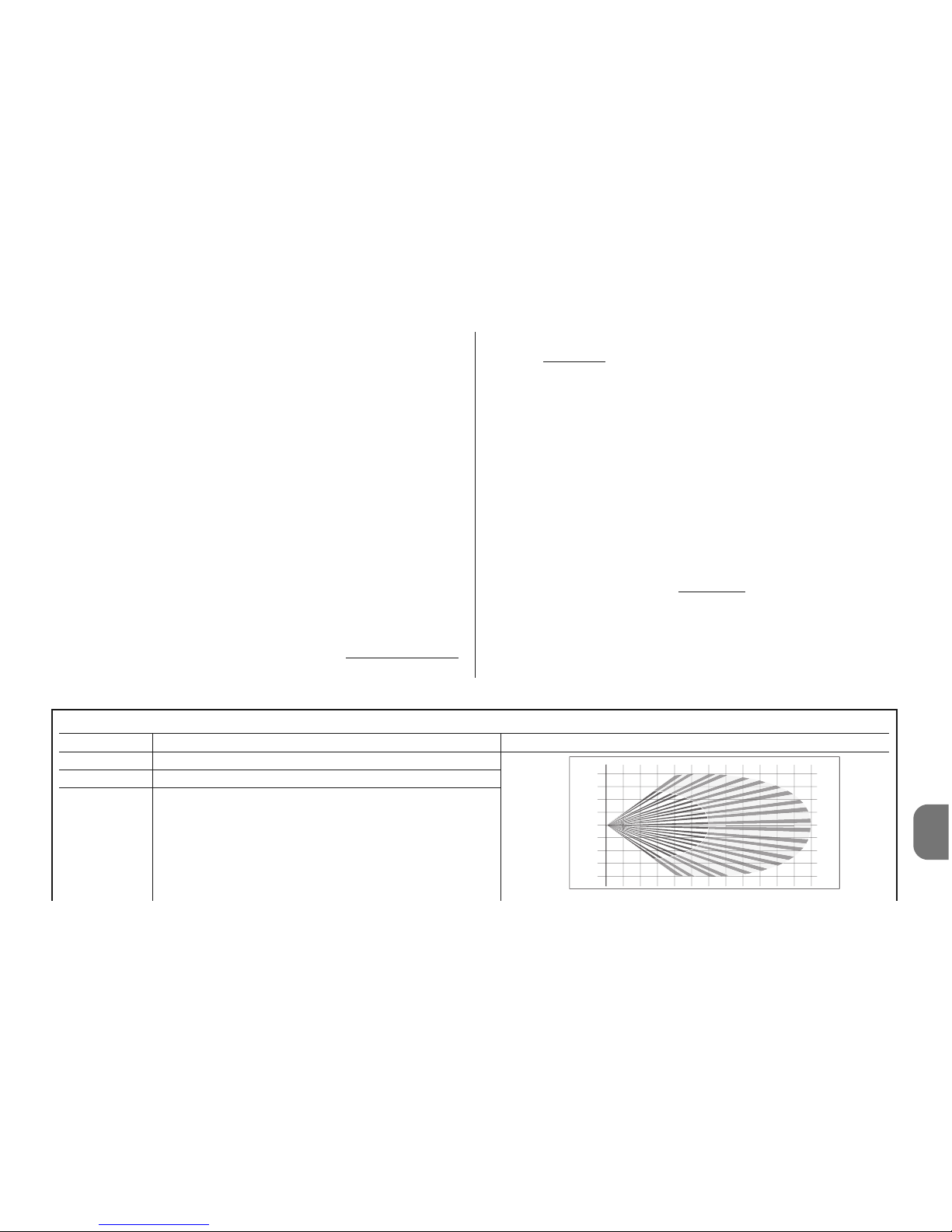
Tabel 1
Dip Switch Functie Opmerkingen
Dip 1 Niet gebruikt
Dip 2 = OFF Gevoelige gebied infraroodsensor tot 6 meter
Dip 2 = ON Gevoelige gebied infraroodsensor tot 12 meter
123456789101112
0
1
2
3
4
4
3
2
1
m
m
NL
06. Programmeer de dip switches (afb. 7) en stel de trim-
mers in (afb. 7), zie hiervoor hoofdstuk 3 - Programmering; voer vervolgens een “Test” van de werking uit, zie
paragraaf 3.1.
07. Sluit het kastje (afb. 8) en bevestig de HSDOM21 aan
zijn bevestigingsbeugel (afb. 9).
3 - PROGRAMMERING
HSDOM21 is voorzien van 5 “dip-switches” (afb. 7) waarmee enkele werkingsparameters geprogrammeerd kunnen
worden en 2 “trimmers” voor de instelling (PT1 en PT2 -
afb. 7): zie Tabel 1 en Tabel 2.
3.1 - Procedure voor programmering en “Test” van
de werking
01. Programmeer eerst de infrarooddetector met 1 impuls
om het alarm af te laten gaan: dip-switch 3 = OFF
(Tabel 1).
02. Programmeer vervolgens de “gevoeligheid” van de infrarooddetector PIR: dip-switch 2 op de minimumwaarde
die nodig is (Tabel 1).
03. Stel de waarde voor de “vertraging na betreding” in op
het minimum
: trimmer PT2 (afb. 7).
04. Stel de waarde van de gevoeligheid van de microgolf
detector in (trimmer PT1 - afb. 7)
05. Controleer de dekking van het beveiligde gebied: maak
korte bewegingen binnen het gebied en controleer de
door de led’s gegeven signaleringen. Stel de gevoeligheidswaarde zo nodig verder bij. Let op! – De lens van
de infraroodsensor is vast op het deksel bevestigd, de
detectietests moeten dus worden uitgevoerd met het
apparaat gesloten.
06. Na de gevoeligheid te hebben ingesteld wordt, om de kans
op onjuiste alarmen te verkleinen, aangeraden dip-switch 3
= ON in te stellen (2 impulsen om een alarm af te laten gaan).
07. Om dezelfde reden stelt u de waarde voor de “vertraging
na betreding” in op het maximum
: trimmer PT2 (afb. 7)
voor zover compatibel met de vereisten die aan de
detectie worden gesteld.
08. Na de werkingscontrole wordt aangeraden de dipswitch 4 = ON in te stellen om de ledsignalering uit te
schakelen.
Nederlands - 3
Page 42
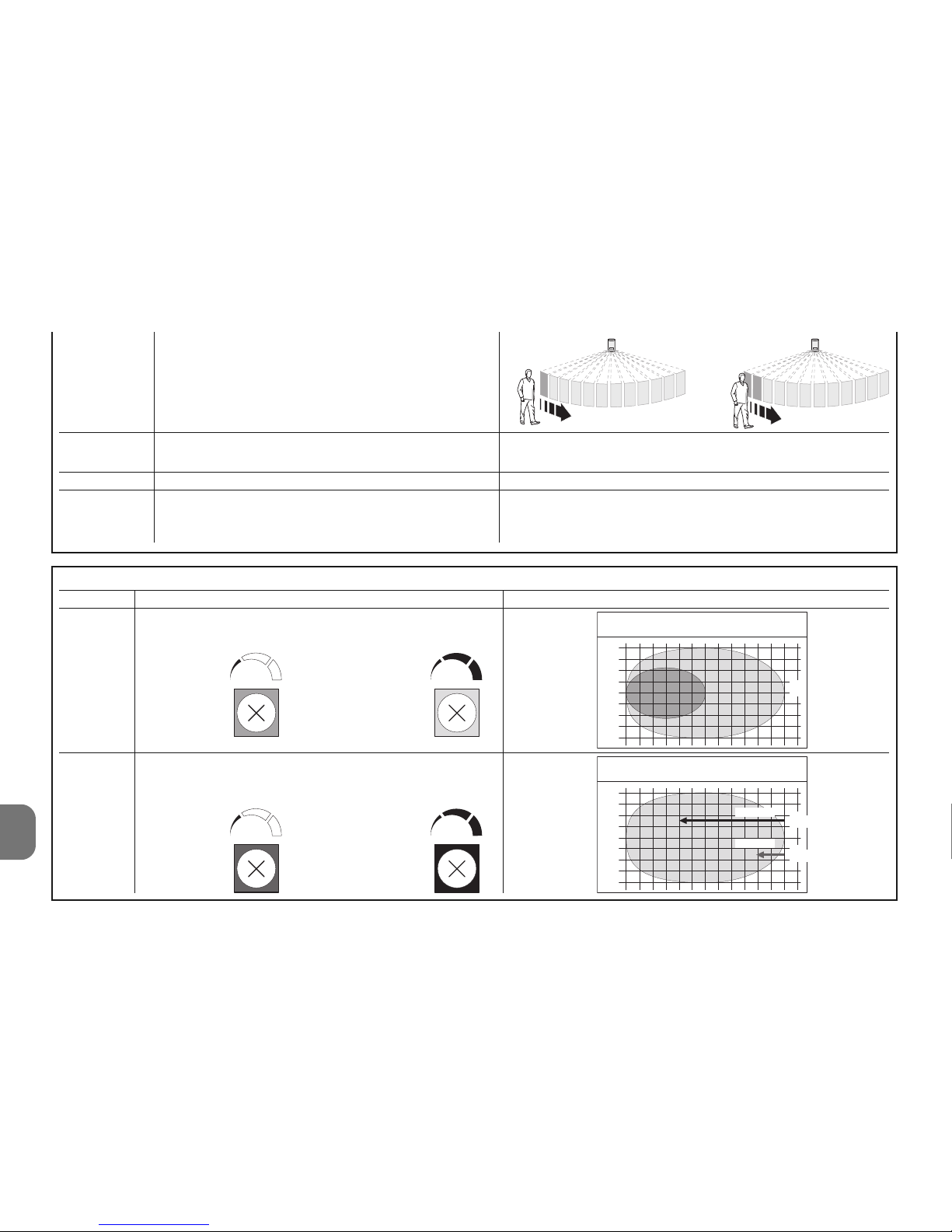
4 - Nederlands
NL
Tabel 2
Trimmer Functie Opmerkingen
PT1 Instelling gebied microgolfsensor
van 6 tot 12 m
PT2 Vertraging na betreding in het gevoelige
gebied voordat het alarm afgaat
1234 56 78 9101112
0
1
2
3
4
4
3
2
1
0
1
2
3
4
4
3
2
1
2,5 sec.
0,25 sec.
m
m
maximum
minimum
Bereik
m
Vertraging
minimum maximum
minimum maximum
Dip 3 = OFF Aantal infraroodpulsen voor alarm = 1
Dip 3 = ON Aantal infraroodpulsen voor alarm = 2
Dip 4 = OFF Signaleringsled's actief
Dip 4 = ON Signaleringsled's uit
Dip 5 Niet gebruikt
Dip 6 = OFF Temperatuurcompensatie gedeactiveerd
Dip 6 = ON Temperatuurcompensatie actief
Let op! – De signalering van de led's brengt een groter
verbruik van de batterijen met zich mee.
Daarnaast veroorzaakt deze functie de gevoeligheid van
de PIR wanneer de omgevingstemperatuur boven de
30°C komt. Activeer deze functie niet als dit niet nodig is.
Page 43
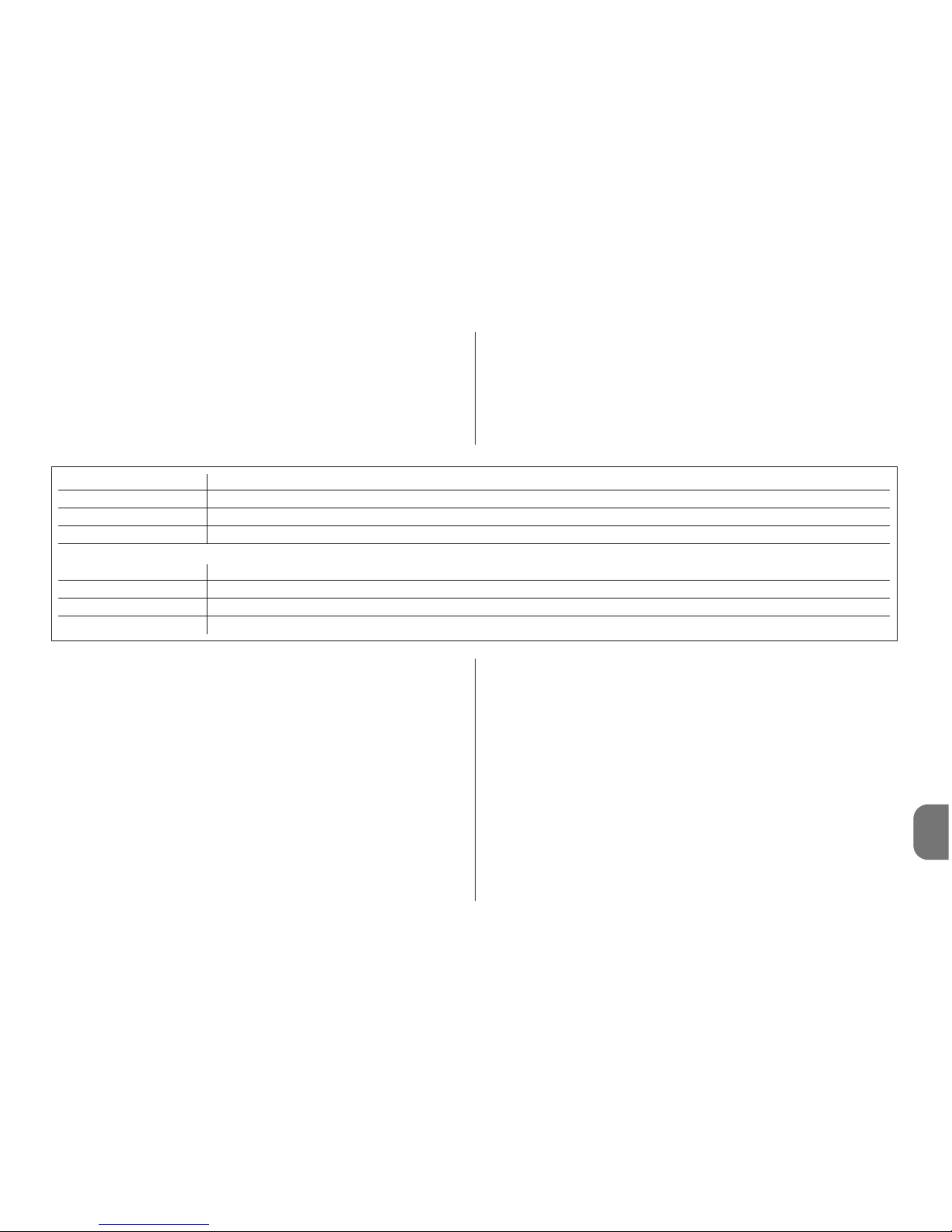
NL
Nederlands - 5
LED Functie
Groen Detectie door infraroodsensor (PIR = OK)
Oranje Vertraging betreding van gebied aan de gang ( MW = ?)
Rood Alarm betreding beveiligd gebied (PIR+MW = OK)
Zoemer Functie
1 pieptoon Alarmsignalering (betreding beveiligd gebied, onklaar maken…)
3+3 pieptonen Programmering sensor (plaatsen batterijen)
5 pieptonen Signalering lege batterijen
4 - VERVANGEN VAN DE BATTERIJEN
Let op! – Er mogen om geen enkele reden andere batte-
rijen dan voorzien worden gebruikt. De batterijen moeten allemaal tegelijk vervangen worden (door nieuwe
exemplaren). Gebruik geen batterijen van verschillende
merken of modellen door elkaar. Gebruik geen oplaadbare batterijen.
Let op! – Alvorens de detector los te maken van de
draagbeugel, dient de besturingseenheid te worden
ingesteld in de modus “TEST BESTURINGSEENHEID”;
dit om onnodige signaleringen wegens ‘onklaar maken’
te vermijden.
01. Om de detector los te maken van de draagbeugel gebruikt
u het hiervoor bestemde blokkeerhendeltje (afb. 3).
02. Laat de detector ongeveer 5 mm naar boven glijden en
verwijder hem vervolgens van de draagbeugel (afb. 3).
03. Open het kastje door de 4 achterste schroeven (afb. 5)
los te draaien.
04. Open het batterijvak zoals aangegeven in afb. 6 en vervang
de batterijen. Neem de aangegeven polariteit in acht.
05. Sluit de detector door de 4 achterste schroeven (afb. 8)
vast te draaien en bevestig de HSDOM21 aan zijn
bevestigingsbeugel (afb. 9).
5 - AFVALVERWERKING ACCU'S EN BATTERIJEN
Let op! – De accu’s en batterijen die gebruikt worden in de
inrichtingen waaruit dit alarmsysteem bestaat, bevatten, ook
wanneer ze leeg zijn, vervuilende stoffen en mogen niet bij
3.2 - Signaleringen
HSDOM21 heeft 1 led met 3 kleuren en een zoemer die
geluidssignaleringen geeft.
De infrarooddetector is altijd actief en in het geval er een
betreding van het beveiligde gebied wordt gedetecteerd
(groene led brandt) wordt onmiddellijk ook de microgolfdetector geactiveerd (oranje led brandt); als ook deze detector
het bestaan van een bewegend lichaam bevestigt, wordt de
alarmstatus gegenereerd (rode led brandt).
De signalering voor lege batterijen wordt 15-30 dagen voordat de batterijen helemaal leeg zijn gegeven. Het verdient
hoe dan ook de voorkeur de batterijen zo snel mogelijk te
vervangen. Met gedeeltelijk lege batterijen is het mogelijk dat
er geen correcte alarmsignaleringen worden gegeven.
Page 44
NL
6 - Nederlands
EG-VERKLARING VAN OVEREENSTEMMING
Opmerking - De inhoud van deze verklaring stemt overeen met hetgeen verklaard is in de laatste
revisie die beschikbaar was voor het ter perse gaan van deze handleiding, van het officiële document dat is neergelegd bij de vestiging van Nice Spa. Deze tekst werd om uitgeversredenen heraangepast.
Nummer: 331/HSDOM21 Revisie: 0
Ondergetekende Luigi Paro, in de hoedanigheid van Gedelegeerd Bestuurder,
verklaart onder zijn eigen verantwoordelijkheid dat het product:
Naam fabrikant: NICE s.p.a.
Adres: Via Pezza Alta 13, Z.I. Rustignè, 31046 Oderzo (TV) Italië
Type: Infrarooddetector met dubbele technologie, werking via
radioverbinding
Modellen: HSDOM21
Accessoires:
Voldoet aan de fundamentele vereisten opgelegd door artikel 3 van de volgende
communautaire richtlijn, voor het gebruik waarvoor de producten bestemd zijn:
• 1999/5/EG RICHTLIJN 1999/5/EG VAN HET EUROPESE PARLEMENT EN
VAN DE RAAD van 9 maart 1999 met betrekking tot radioapparatuur en eindtelecommunicatieapparatuur en de wederzijdse erkenning van hun conformiteit
Volgens de volgende geharmoniseerde normen
bescherming van de gezondheid: EN 50371:2002; elektrische veiligheid: EN
60950-1:2006; elektromagnetische compatibiliteit: EN 301 489-1V1.8.1:2008;
EN 301 489-3V1.4.1:2002; radiospectrum: EN 300220-2V2.1.2:2007, EN3004402V1.3.1.:2009
In overeenstemming met de richtlijn 1999/5/EG (bijlage V), behoort het product
tot de klasse 1 en draagt het de markering:
Bovendien voldoet het product aan hetgeen voorzien wordt door de volgende
communautaire richtlijnen:
• 2004/108/EEG(ex richtlijn 89/336/EEG) RICHTLIJN 2004/108/EG VAN HET
EUROPESE PARLEMENT EN DE RAAD van 15 december 2004 met betrekking tot de onderlinge aanpassing van de wetgevingen van de Lidstaten met
betrekking tot de elektromagnetische compatibiliteit waarmee de richtlijn
89/336/EEG wordt afgeschaft
Volgens de volgende geharmoniseerde normen:
EN 50130-4:1995+A1:1998+A2:2003
Oderzo, 20 november 2009
Ing. Luigi Paro (Gedelegeerd Bestuurder)
0682
het gewone huisafval worden gedaan. De batterijen dienen
als afval te worden verwerkt volgens gescheiden afvalverzamelingsmethoden, zoals voorzien door de voorschriften die
van kracht zijn in uw land.
6 - TECHNISCHE KENMERKEN
Waarschuwingen: • Alle vermelde technische kenmerken hebben
betrekking op een omgevingstemperatuur van 20°C (± 5°C). • Nice
S.p.a. behoudt zich het recht voor om, op elk moment dat dit noodzakelijk geacht wordt, wijzigingen aan het product aan te brengen, waarbij hoe dan ook de functionaliteit en de gebruiksbestemming ervan
gelijk blijven.
■ Typologie: volumedetector met dubbele technologie,
infrarood (PIR) en microgolfradar (MW); voor gebruik buitenshuis. Beveiliging tegen opening en verwijdering ■ Voeding:
4,5V met 3 batterijen 1,5V type AA of equivalent ■ Opgeno-
men stroom: 70 µA in rust- 40 mA tijdens het uitzenden ■
Autonomie: geschat op 2 jaar (met Dip 4 = ON), met signa-
lering voor lege batterij. ■ Radio-overdracht: digitale communicatie, op dubbele frequentie “DualBand” (433 en
868MHz) kristalfrequentieregeling; de inrichtingen worden in
de fabriek voorgecodeerd en via zelflering beheerd ■ Radio-
bereik: 100 meter in open ruimtes en zonder storing; circa
20 meter in gebouwen ■ Isolatie: klasse III ■ Microgolffre-
quentie: 9,9 GHz ■ Maximumvermogen microgolf: < 20
mW (conform EN 50371); voor een ononderbroken tijd van
maximaal 5s ■ Beschermingsklasse van het kastje: IP 65
■ Bedrijfstemperatuur: van -25°C tot +55 °C ■ Gebruik in
ruimtes met omgevingsklasse: II ■ Montage: aan de
wand ■ Afmetingen (mm): 158 x 83 x 50 ■ Gewicht: 0,37
kg
Page 45
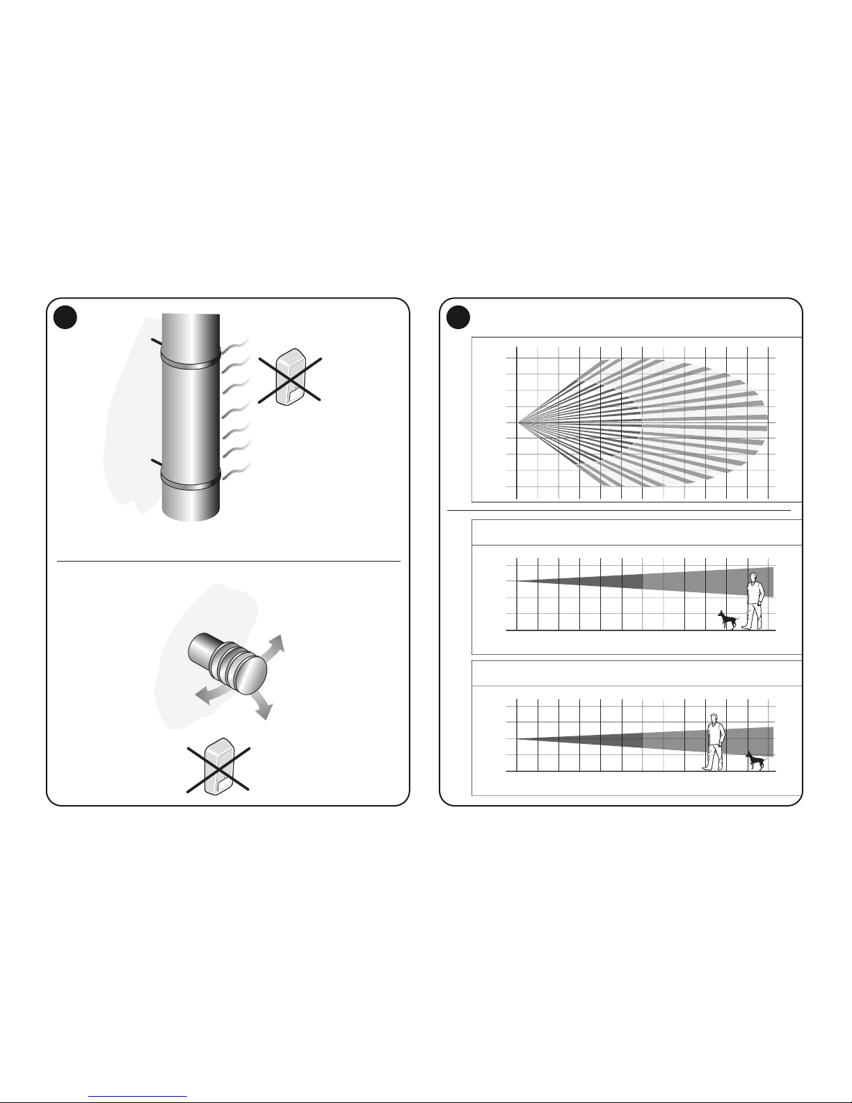
1
123 4567 89101112
123456789101112
0
1
2
3
4
4
3
2
1
0
1
2
1,5
0,5
123 4567 89101112
0
1
2
1,5
0,5
2
m
m
m
P.I.R. RANGE - SIDE VIEW
P.I.R. RANGE - SIDE VIEW
P.I.R. RANGE - TOP VIEW
m
m
Page 46
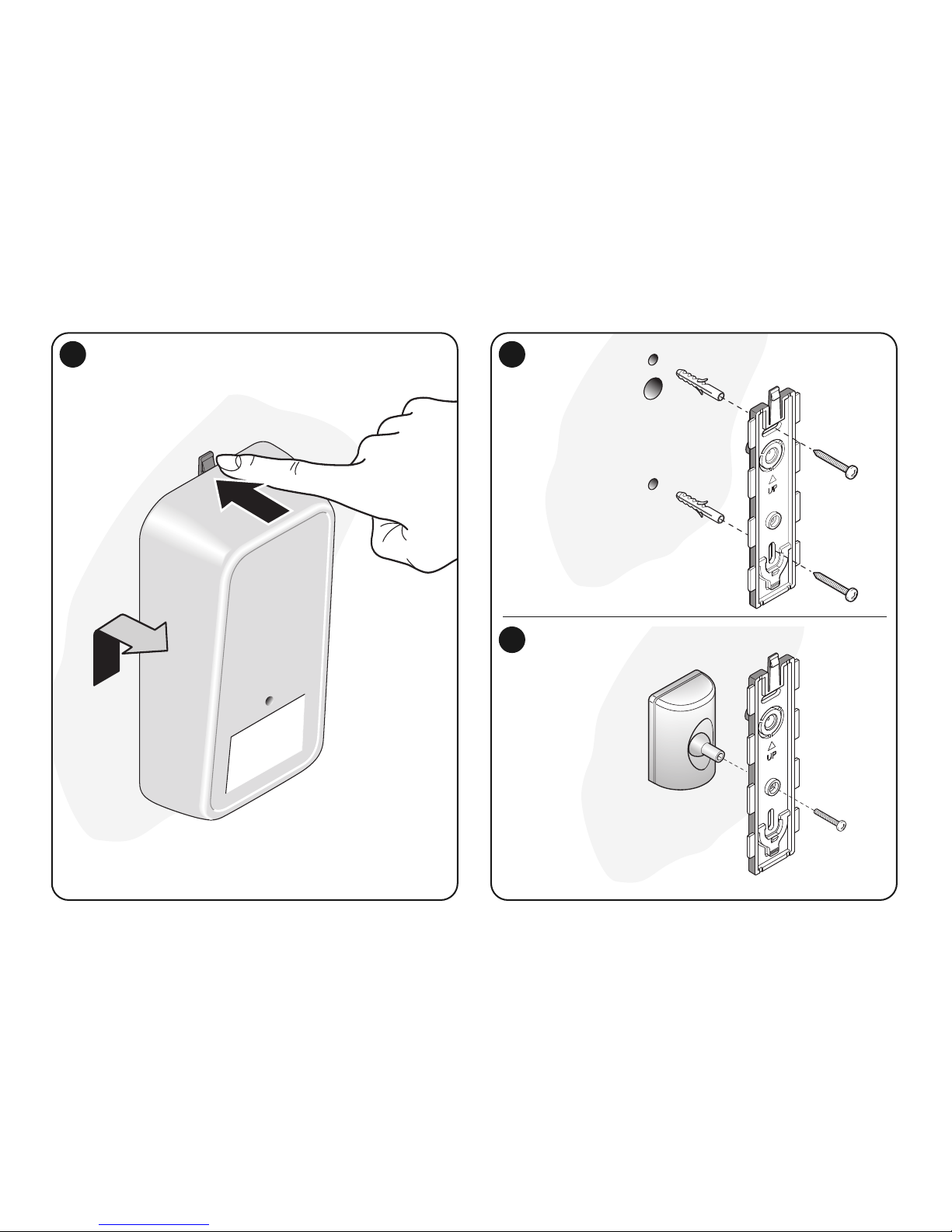
1
2
3 4
A
4
B
HSA3
Page 47
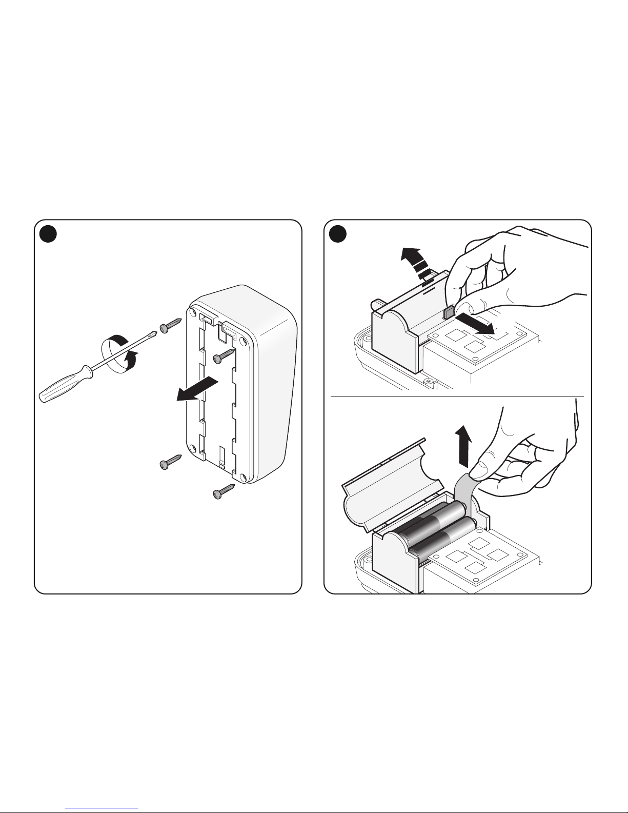
5
2
1
6
Page 48
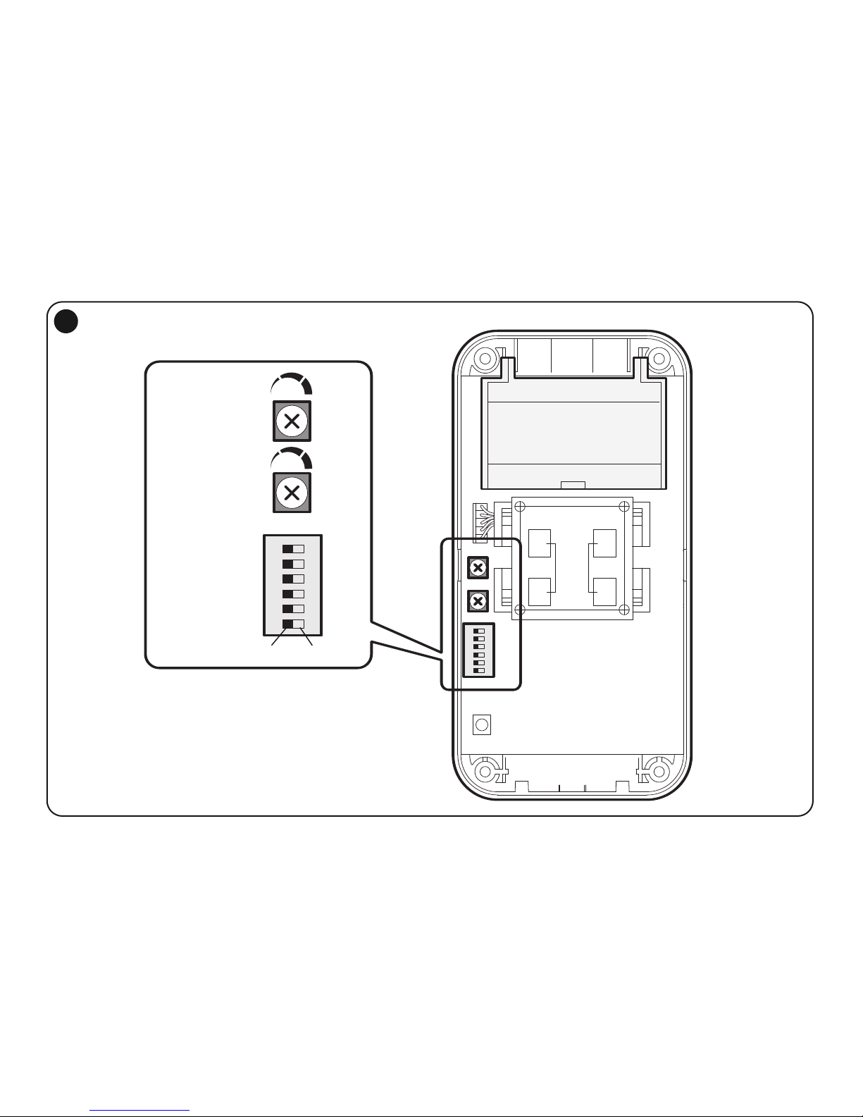
123456
7
Dip
Switch
PT1
PT2
OnOff
–+
–+
Page 49
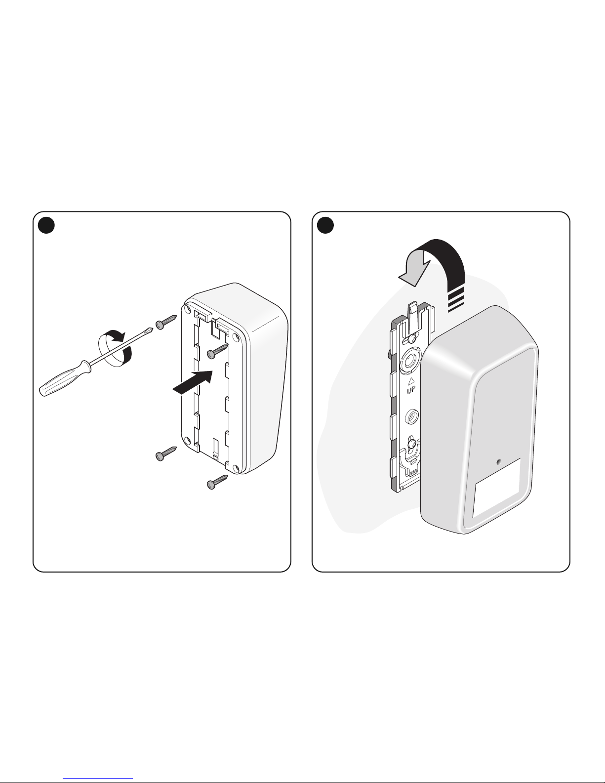
8 9
Page 50

Page 51

Page 52

IST318.4862 – Rev.00 – 15-01-2010
Headquarters
Nice SpA
Oderzo TV Italia
Ph. +39.0422.85.38.38
Fax +39.0422.85.35.85
[email protected]
www.niceforyou.com
 Loading...