

DPRO924
Nice
Control unit
EN - Instructions and warnings for installation and use
C
A D
F
E
B
9
6
5
8
2
3
8
44
7
1
2
1
210
210
125
310
I

3
A B
4
A B C
6
1
2
1
2
FUSE
FUSE
OXI New Generetion
OXI/SMXI
II

ENGLISH
EN
original operating instructions in Italian
Contents
Pictures .......................................................................................................I-II
GENERAL WARNINGS: SAFETY - INSTALLATION - USE ............................1
1 - PRODUCT DESCRIPTION AND INTENDED USE ...................................2
2 - INSTALLATION .........................................................................................2
2.1 - Pre-installation checks ...........................................................................2
2.2 - Product application limits .......................................................................2
2.3 - Typical system .......................................................................................2
2.4 - Control unit installation ...........................................................................2
3 - ELECTRICAL CONNECTIONS ................................................................3
3.1 - Connection description .........................................................................3
3.2 - Control unit electrical connections .........................................................4
3.3 - STOP SAFETY EDGE input ....................................................................4
3.4 - Connecting a radio receiver ...................................................................5
3.5 - Connecting other devices to the control unit .........................................5
3.6 - Oview programming unit ........................................................................5
3.7 - First start-up and checking the connections ......................................... 5
4 - PROGRAMMING .....................................................................................6
4.1 - Control unit buttons ..............................................................................6
4.2 - Total deletion of the control unit’s memory .............................................6
4.3 - Learning about the safety devices and DIP SWITCH programming ........6
4.4 - Learning about the Opening and Closing positions with an incremental ..
encoder .................................................................................................6
4.5 - Operating modes ..................................................................................7
4.5.1 - Setting the automatic closing pause time ...................................7
4.5.2 - Modifying the pause time value ..................................................7
4.5.3 - Modifying the speed value ..........................................................8
5 - TESTING AND COMMISSIONING ...........................................................8
5.1 - Testing ...................................................................................................8
5.2 - Commissioning ......................................................................................8
6 - FURTHER DETAILS .................................................................................9
6.1 - Connecting photocells and accessories in standby mode ......................9
6.2 - Connecting photocells in “Phototest” mode ...........................................9
6.3 - Connecting a buffer battery..................................................................10
6.4 - Connecting the status light and diagnostics .........................................10
6.5 - Open and Close control block (using the buttons on the box lid) .........10
7 - DIAGNOSTICS .......................................................................................10
7.1 - Messages on turning on ......................................................................10
7.2 - Diagnostics ..........................................................................................10
8 - PRODUCT DISPOSAL ...........................................................................11
9 - PRODUCT TECHNICAL FEATURES ......................................................11
CE DECLARATION OF CONFORMITY ........................................................12

English – 1
EN
GENERAL WARNINGS: SAFETY - INSTALLATION - USE (original instructions in Italian)
CAUTION Important safety instructions. Follow all instructions as improper installation may cause serious damage
CAUTION Important safety instructions. It is important for you to comply with these instructions for your own and other
people’s safety. Keep these instructions
• Before commencing the installation, check the “Product technical specications”, in particular whether this product is suitable for automating
your guided part. If it is not suitable, DO NOT continue with the installation.
• The product cannot be used before it has been commissioned as specied in the chapter on “Testing and commissioning”
CAUTION According to the most recent European legislation, the implementation of an automation system must comply
with the harmonised standards provided by the Machinery Directive in force, which enables declaration of
the presumed conformity of the automation. Taking this into account, all operations regarding connection to
the electricity mains supply, as well as product testing, commissioning and maintenance, must be performed
exclusively by a qualied and skilled technician!
• Before proceeding with the installation of the product, check that all materials are in good working order and suited to the intended applications
• The product is not intended for use by persons (including children) with reduced physical, sensory or mental capacities, nor by anyone with
insufcient experience or familiarity
• Children must not play with the appliance
• Do not allow children to play with the control devices of the product. Keep the remote controls out of reach of children.
CAUTION In order to avoid any danger from inadvertent resetting of the thermal cut-off device, this appliance must not be
powered through an external switching device, such as a timer, or connected to a supply that is regularly powered
or switched off by the circuit
• Provide a disconnection device (not supplied) in the plant’s mains power supply, with a contact opening distance that permits complete
disconnection under the conditions dictated by overvoltage category III
• Handle the product with care during installation, taking care to avoid crushing, denting or dropping it, or allowing contact with liquids of any
kind. Keep the product away from sources of heat and naked ames. Failure to observe the above can damage the product, and increase the
risk of danger or malfunction. If this should happen, stop installation immediately and contact Customer Service.
• The manufacturer assumes no liability for damage to property, items or persons resulting from non-compliance with the assembly instructions.
In such cases the warranty for material defects is excluded
• The weighted sound pressure level of the emission A is lower than 70 dB(A)
• Cleaning and maintenance to be carried out by the user must not be carried out by unsupervised children
• Before working on the system (maintenance, cleaning), always disconnect the product from the mains power supply
• Check the system periodically, in particular all cables, springs and supports to detect possible imbalances, signs of wear or damage. Do not use
if repairs or adjustments are necessary, because a failure with the installation or an incorrectly balanced automated system may lead to injury
• The packing materials of the product must be disposed of in compliance with local regulations
Special warnings in relation to European directives applicable to the product
• “Construction Products” Regulation: Special warnings for this product in relation to Regulation 305/2011:
- The full installation of this product, as described in this instruction manual and for certain types of use (e.g. excluding use solely for vehicles)
may cause the product to fall within the scope of Regulation No. 305/2011 and its harmonised standard EN 13241-1.
- It is necessary to apply all the installation criteria to ensure that the product meets the essential requirements of Regulation No. 305/2011;
the installer must check and make sure that all these criteria have been scrupulously complied with.
- The essential requirements might not be guaranteed if the product is installed and used without compliance with one or more of these
criteria. It is forbidden to use the product in such circumstances until the installer has veried compliance with the Directive requirements;
in this case the “ES13241-1.4870” label attached to the product must be removed immediately and the “EC Declaration of Conformity”
(Annex I to this manual) cannot be used. As a result, the installer in turn becomes the manufacturer of the product and must comply with
the provisions of Regulation No. 305/2011 and its harmonised standard EN 13241-1. In this case the product must be considered as
“partly-completed machinery” and the “Declaration of Conformity” of Annex II can be used (for inclusion in the technical documentation).
• “Low Voltage” Directive:
Special warnings regarding the tness of use of this product in relation to the “Low Voltage” Directive. This product meets the requirements
in the “Low Voltage” Directive, if used for the use and in the congurations specied in this instruction manual and in combination with the
items in the Nice S.p.a. product catalogue.
If the product is used in unspecied congurations or with other unspecied products, the requirements may not be guaranteed; the use
of the product in such circumstances is prohibited until the installer has veried compliance with the specied requirements of the directive.
• “Electromagnetic compatibility” Directive:
Special warnings regarding the tness of use of this product in relation to the “Electromagnetic compatibility” Directive.
This product has been subjected to electromagnetic compatibility tests in the most critical situations of use and in the congurations specied
in this instruction manual and in combination with the items in the Nice S.p.a. product catalogue.
If the product is used in unspecied congurations or with other unspecied products, the electromagnetic compatibility may not be guaranteed; the use of the product is prohibited in such circumstances until the installer has veried compliance with the specied requirements
of the directive.
Installation criteria and special warnings in connection with essential requirements
• When installed correctly, this product meets the essential requirements laid down in Regulation No. 305/2011 according to the requirements
in harmonised standard EN 13241-1, as indicated in Table 1 and in the European directive on “Machinery” 2006/42/EC.
• Release of dangerous substances:
The product does not contain and/or release hazardous substances in accordance with the requirements of EN 13241-1, 4.2.9 and according to the list of substances on the website of the European Community
Special warning to ensure the continued compliance with the requirement – It is essential that the other materials used in the installation,
such as electrical cables, comply with this requirement.
• Safe opening for vertically moving doors: the product does not cause uncontrolled movements.
Special warnings to ensure continued compliance of the requirements:
- Install the product carefully following all the instructions described in Chapter “2 - Installation” and Chapter “5 - Testing and commissioning”.
- Ensure that a maintenance schedule is organised which scrupulously complies with all the provisions in the Chapter “Maintenance
Schedule”.

2 – English
EN
1
PRODUCT DESCRIPTION AND INTENDED USE
DPRO924 is a control unit to be used to automate sectional balanced doors. It can control motors with an encoder or Hall effect position control system or using
electromechanical limit switches.
DPRO924 is particularly suitable to be connected to Sumo motors and Opera System devices.
Available accessories: receivers with “SM” (SMXI, OXI, etc.) coupling.
CAUTION! – All uses other than the intended use described and use in environmental conditions other than those described in this manual
should be considered improper and forbidden!
2
INSTALLATION
2.1 - Pre-installation checks
Before proceeding with installation, check the condition of the product components, suitability of the selected model and conditions of the intended installation
environment:
• Check that all conditions of use fall within the “application limits” of the product (paragraph 2.2) and the value limits shown in the “Product technical characteristics” (chap. 9).
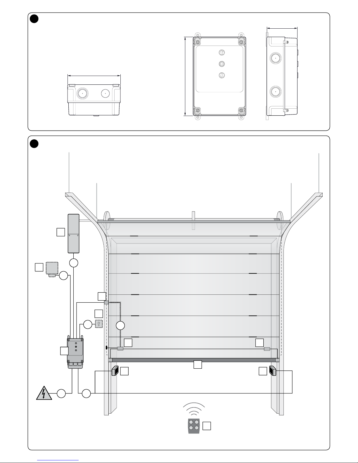
• Check that the installation location is compatible with the overall dimensions of the product (Fig. 1).
• Check that the surface chosen for installing the product is solid and can ensure stable attachment.
• Make sure that the installation area is not subject to ooding; if necessary, the product may be installed, appropriately raised above ground level.
• Check that the space around the product allows safe and easy access.
• Check that all electrical cables to be used belong to the type listed in Table 1.
• Check that the automation has mechanical stops in both the opening and closing phases.
2.2 - Product application limits
The product can be used only on sectional balanced doors with Nice motors of the Sumo family.
CAUTION! – The control unit described in this instruction manual cannot be used in areas at risk of explosion.
2.3 - Typical system
Fig. 2 provides an example of an automation system, produced using Nice components:
1 Gearmotor 6 Spiral cable
2 Transmitter 7 Flashing light
3 Sensitive edge 8 Photocell
4 Junction box 9 Digital keyboard - Transponder reader - Key selector switch - Push button panel
5 Control unit
These parts are positioned according to a typical standard layout. With reference to Fig. 2, locate the approximate position for installation of each component
envisaged in the system.
Important – Before installation, prepare the necessary electrical cables as per g. 2 and Table 1.
Caution! – When laying the ducting for routing the electrical cables and for the cable entry point into the control unit housing, be aware that due to possible
deposits of water in the junction wells, the connection ducts might create condensate in the control unit, with consequent damage to the electronic circuits.
2.4 - Installation of the control unit
01. Open the control unit box: unscrew the screws as shown in Fig. 3-A / Fig. 3-B;
02. Prepare the holes for routing the electrical cables for the accessories providing control and/or signalling functions. For this purpose, we recommend using
a special tool (e.g. hole cutter) on the marked positions at the bottom of the box, also to ensure maintaining the level of IP protection. If necessary, you can
use the lateral cable entry points, but only by using suitable ducting connections;
03. Secure the box: it can be xed in three ways:
a) directly onto the wall using the screws from inside the box (Fig. 4-A);
b) using the standard supports supplied (Fig. 4-B);
c) if the cable duct for routing the electrical cables is on the outside and you need to x the box at a maximum distance of 2 cm away from the wall to allow
the cables to be routed behind the control unit. NDA100 consists of 4 spacers and a protective cover for introducing the cables inside the control unit box.
To install the unit using the (optional) accessory, see Fig. 4-C.
04. At this point, you can make all the electrical connections: see Chapter 3.
To install the other devices used on the automated system, refer to the respective instruction manuals.
TABLE 1 - Technical specications of electrical cables (Fig. 2)
Connection Cable type Maximum admissible length
A: CONTROL UNIT CONNECTION cable 3 x 1.5 mm
2
30 m (note 1)
B: MOTOR cable 3 x 2.5 mm
2
10 m
C: ENCODER/LIMIT SWITCH cable Encoder: 2 x 1 mm
2
Limit switch: 4 x 0.75 mm
2
10 m
20 m
• As regards the risks of crushing and impact, the doors are protected by means of one of these three methods:
1 - For operation with “hold-to-run command” (man present): as specied in EN 12453, point 5.1.1.4. In this case the command button
must be placed in view of the automation and if it is accessible to the public, the command button must not be available to them, e.g.
use only with a key switch.
2 - For “Semi-automatic” operation: through the use of an active sensitive edge for limiting the forces as specied in EN 12453, paragraphs
5.1.1.5 and 5.1.3.
3 - For “automatic” operation: through the use of an active sensitive edge for limiting the forces as specied in EN 12453, paragraphs 5.1.1.5
and 5.1.3; in this case, at least one pair of photocells must be installed as shown in Fig. 2.
English – 3
EN
D: FLASHER cable with aerial 2 x 0.5 mm2 (for asher 24V )
RG58-type screened cable (for aerial)
20 m
10 m (5 m recommended)
E: PHOTOCELL cable 4 x 0.5 mm
2
20 m
F: KEY SWITCH cable 2 x 0.25 mm
2
cables 20 m
G: COILED cable for sensitive edge
Note 1 – If the power cable exceeds 30 m in length, a cable with a larger section (3 x 2.5 mm
2
) must be used and safety grounding near the automation must
be installed.
Note 2 – These 2 cables can be replaced with just one 4 x 0.5 mm
2
cable
CAUTION! – The cables used must be suitable to the type of room where the unit is installed.
3
ELECTRICAL CONNECTIONS
CAUTION!
– Before you proceed to make any electrical connections make sure that the power supply is disconnected;
– Connections must only be carried out by qualied personnel.
– You must put a device on the electricity supply line that ensures complete disconnection of the automated mechanism from the mains supply. The discon-
nection device must have contacts with an opening distance large enough to permit complete disconnection under the conditions sanctioned by overvoltage
category III, in accordance with installation regulations. The device ensures quick, safe disconnection from the power supply if needed, and must therefore
be in a position that is visible from the automation mechanism. If, on the other hand, it is located in a position which is not visible, there must be a system for
preventing accidental or unauthorised reconnection to the mains supply to prevent this risk. The disconnection device is not supplied with the product.
3.1 - Connection description
Find below the description of the meaning of the marks printed on the electronic board at the relative terminals:
PUSH BUTTONS Input for the connections of the buttons on the box lid
24V
Ground
Input for the connection of the transformer power
Battery (symbol) Connector for the connection of the buffer battery mod. PS224
Incremental encoder Terminal for the connection of the encoder of the Sumo- family motors - No polarity to comply with
Motor
Terminal for the connection of the electrical motor and the ground
Attention to polarity: connect the motor so that, when the opening command is given, the opening of the door matches it on the
control unit
1: 24V
motor
2: 24V
motor
3:
motor
Limit Switch
(function unavailable)
Connector for the electromechanical limit switch connection:
Common: limit switch common
Open: input of maximum opening limit switch
Preclose: input of the preclosing limit switch, adjusted at about 3 cm above the closing limit switch. The detection of obstacles, or
sensitive edge, between the closing and pre-closing position, stops the closing movement and the control unit considers the door in
completely-closed position.
Open: input of maximum closing limit switch
IBT4N Input for the connection of the Oview programmer, with the appropriate IBT4N adapter.
CAUTION! - Disconnect the power before connecting/disconnecting the programmer.
Aerial
Input for the connection of the radio receiver aerial (note: in Nice ashers Mod. ELDC, the aerial is built-in)
STOP Input for the connection of resistive-type sensitive edges (8k2) or optical ones (OSE), as described below (g. 5):
OSE connection:
- positive 12V
(+) (brown wires)
- signal (S) (green wires)
- negative GND (-) (white wires)
Connection 8k2:
- Connect the 8.2 kΩ resistance between the Signal and GND terminals
Common 24V output
(-30%; +50%) acting as common for the SbS input; when the control unit is in Standby mode (low consumption), this
output is not off.
Sbs Input for a NO (normally open) button to send commands in Step-by-Step mode; input recongurable using the Oview programmer.
COM SBY
24V output
(-30%; +50%) acting as common for the Open, Close, Photo and Photo2 inputs; when the control unit is in Stand by
mode (low consumption) this output is off
Open Input for a NO (normally open) button to send commands in Open mode; input recongurable using the Oview programmer.
Close Input for a NO (normally open) button to send commands in Close mode; input recongurable using the Oview programmer.
Photo Input for Photocell-type safety devices with NC (normally closed) contact; the intervention takes place during the closing manoeuvre.
Photo2 Input for Photocell-type safety devices with NC (normally closed) contact; the intervention takes place during the closing manoeuvre.
GND Negative GND
24V 24V output
(-30%; +50%) 200mA to power services; when the control unit is in Standby mode (low consumption), this output is
not off.
Phototest 24V output
(-30%; +50%) 200mA to power photocells in phototest mode; when the control unit is in Standby mode (low con-
sumption), this output is not off.
Out1 (Flash) Output for asher at 24V 25W with self-ashing (ELDC)

4 – English
EN
Out2 Clean contact relay output (maximum resistive load 3A)
Out3 Clean contact relay output (maximum resistive load 3A)
IMPORTANT! - We DO NOT recommend that you connect any device or accessory not mentioned in this instruction manual. The manufacturer
declines all responsibility whatsoever for any damage due to improper use of the various system devices that does not comply with the instructions in this manual. For more information, please contact the Nice Customer Service.
3.2 - Collegamenti elettrici della centrale di comando (g. 5)
CAUTION! – Before you proceed to make any electrical connections make sure that the mains power supply is disconnected and the buffer
battery are disconnected.
After xing the box of the control unit and prepared the holes for the electric cables (paragraph 2.4), make the connections as shown in g. 5.
1
2
TX
1 2
RX
FLASH
24 V
PHOTO 2
24V …
—
24V …
0V
0V
0V
0V
—
24V …
—
24V …
—
24V …—24V …
—
PHOTO
8K2
NC
NO NO NO
21 543
TX
1 2
RX
21 543
M1
FUSE
FUSE
5
3.3 - STOP SAFETY EDGE Input
STOP
8k2
8,2 kΩ
brown - 12V DC
green - Segnale
white - GND/0V
+ SIG -+ SIG -
STOP STOP
The function of the SAFETY EDGE input is to cause the immediate stop of a
manoeuvre when in progress followed by a short reverse manoeuvre.
This input can be connected to devices such as optical sensitive edges (OSE) or
those with 8.2 kΩ constant resistance output.
During the recognition phase, the control unit recognises the type of device connected and causes a “STOP” whenever any variation in the recognised status
occurs.
Multiple devices, even of different types, can be connected to the STOP SAFETY
EDGE input if appropriately organised:
- NO devices: connect the 8.2 kΩ resistor in parallel to the device;
- NC devices: connect the 8.2 kΩ resistor in series to the device;
- You can connect multiple NC devices “in series” with each other without
quantity limits;
- If there are multiple devices, all must be connected “in cascade” with a single
8.2 kΩ terminal resistance;
- You can also create a combination of NO and NC types, by placing the two
contacts “in parallel”. In this case, you need to place a 8.2 kΩ resistance “in
series” with the NC contact; this also makes it possible to put three devices
together: NO, NC and 8.2 KΩ.
CAUTION! - After connecting the safety device, it is necessary to carry out the “Learning about the safety devices” phase (paragraph 4.3).
3.4 - Connecting a radio receiver
The control unit has an SM connector for connecting an SMXI, SMXIS, OXI, OXI New Generetion, OXIBD or OXIT or similar radio receiver (optional accessory,
not supplied).
To connect the radio receiver, you must disconnect the mains power supply from the control unit and insert the receiver as shown in Fig. 6.
Table 2 shows the actions performed by the control unit according to the activated outputs or the commands sent by the radio receiver.
Note - For further information, refer to the instruction manual for the receiver.

English – 5
EN
TABLE 2
SMXI, SMXIS Receiver in “Mode 1 or 2”
output description
Output No. 1 Step-by-Step
Output No. 2
Partial open; factory setting: opens 1/4 of the stroke
(this may be changed during the position acquisition
phase or by using the Oview programmer)
Output No. 3 Open
Output No. 4 Close
OXI, OXIT receiver programmed in “extended Mode 2”
command description
Command No. 1 Step-by-Step
Command No. 2
Partial open; factory setting: opens 1/4 of the stroke
(this may be changed during the position acquisition
phase or by using the Oview programmer)
Command No. 3 Open
Command No. 4 Close
Command No. 5 Stop
Command No. 6 Step-by-Step Condominium
Command No. 7 Step-by-Step High priority
Command No. 8 Partial open 2
Command No. 9 Partial open 3
Command No. 10 Open and Lock automation
Command No. 11 Close and Lock automation
Command No. 12 Lock automation
Command No. 13 Release automation
Command No. 14 Timed Courtesy light
Command No. 15 Courtesy light ON/OFF
3.5 - Connecting other devices to the control unit
- GND
+ 24V
If it is necessary to power more devices in the system (e.g. transponder card
reader, light for the key selector, etc.), they can be connected to the control
unit using the “GND“ and “24V ” terminals.
The power supply voltage is 24V (-30% ÷ +50%) with 200mA maximum
available current.
3.6 - Oview programming unit
d
b
c
ON
a
OFF
Using the Oview programming unit allows you to manage the installation, maintenance and diagnosis of the entire automated system in a thorough and rapid manner.
You can connect Oview to the control unit via the IBT4N interface using a bus cable
with 4 wires inside.
To access the BusT4 connector, you need to open the control unit box, plug the
IBT4N connector into the appropriate slot and then connect the Oview programmer.
Oview can be used at a maximum cable distance of 100 metres from the control unit;
it can be connected simultaneously to multiple control units (up to 16) and can remain
connected even during normal operation of the automated system. When working
with Oview, it is very important to observe the instructions in the Oview instruction
manual.
If there is an OXI radio receiver in the control unit, when you use Oview you can have
access to the parameters of the transmitters memorised in the receiver. For further
information, refer to the Oview instruction manual or the control unit function sheet
available from the website www.niceforyou.com
CAUTION! - If the functions of Table 3 are programmed with the Oview programming unit, it is necessary to set the dip switches to OFF.
3.7 - First start-up and checking the connections
After powering the control unit, check:
• that the OK led (located near the dip switches) regularly ashes green once every second.
• if there are photocells in the system, check that their leds ash (RX); the type of ashing is not signicant because it depends on other factors.
• that the leds of the ALT, Photo and Photo2 inputs are on with xed lights (see Table 6 - paragraph 7.2).
If at least one of these checks is not as required, disconnect the control unit from the mains and check the electrical connections you made.

6 – English
EN
4.1 - Control unit buttons
8
The “OPEN”, “STOP”
and “CLOSE” buttons
are to be used to control the automated
system and for the
programming phase
OPEN
STOP
CLOSE
ON
A B
1 2 3 1 2 34
ON
OFF OFF
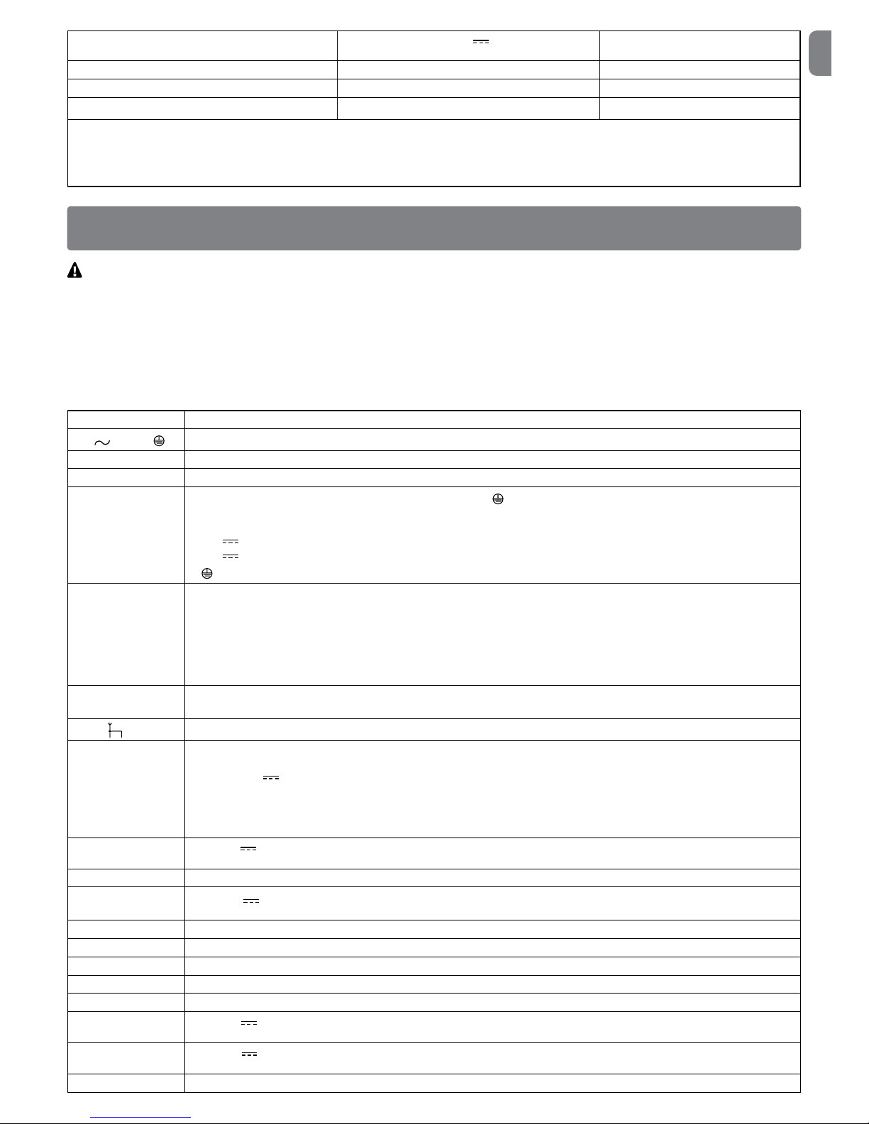
4.2 - Total deletion of the control unit memory
You can delete all the data stored on the control unit and restore it to its original
state with the default settings.
01. Set dip switch A 1-2-3-4
to ON = the led ashes
quickly with orange light
ON
1 2 3 4
A
02. Keep the STOP button
pressed for 3 seconds
until the led is on with
xed red light
3”
03. Release the STOP
button
04. At this point the control
unit does a RESET = the
led ashes quickly with
orange light
RESET
05. Set dip switch A 1-2-3-4
to OFF = the led ashes
with green light
OFF
1 2 3 4
A
4.3 - Learning about the safety devices and DIP SWITCH pro-
gramming
After switching on for the rst time (paragraph 3.7) and before setting the door
Opening and Closing positions, the control unit must recognize the:
- safety devices connected to the “STOP Safety Edge” input
- photocell connection in standard or phototest mode
- settings of dip switches A and B.
NOTE: when dip switch A or B is modied, the OK led ashes alternatively
green and red to highlight that the device learning phase must be carried out
again.
CAUTION! - During the learning phase, at least one safety device
must be connected to the control unit.
01. Set dip switch A-1 to
ON = the led ashes
quickly with green light
ON
OFF
1 2 3 4
A
02. Keep the STOP button
pressed for 3 seconds
until the led is on with
xed red light (after
about 3 seconds)
3”
4
PROGRAMMING
03. Release the STOP
button
04. Set all dip switches to
OFF = the green led
ashes slowly or as per
previous programming
OFF
1 2 3 4
A
1 2 3
B
This procedure must be repeated when a change to the “STOP Safety Edge”
terminal (e.g. after connecting a device to the control unit) or the phototest
connection or dip switches A or B is made.
After learning about the safety devices in the automation, the control unit must
recognize the door Opening and Closing positions.
CAUTION! - The procedures to learn about the safety devices and the
door Opening and Closing positions must be carried out one after the other
and without interruptions. They cannot be performed at different times.
CAUTION! - Procedure for motors with incremental encoders: after per-
forming the Opening and Closing position learning procedure, the control unit
must perform a self-learning procedure of the forces (5 cycles of complete
manoeuvres, the door stops in the Closing position).
4.4 - Learning the Opening and Closing positions with an
incremental encoder
3 positions can be programmed, as described below:
Position Action Meaning
0 Close Maximum closing value. When the door
reaches this position, it stops; this match-
es the mechanical stop (generally the oor).
It can be programmed with the electronic
board or Oview programmer.
1 Opening
stop
Door maximum opening position, corresponding to the opening mechanical stops (M in the
picture below). The opening value must be
smaller than this point.
A Open
Door stop desired position during opening
(does not match the opening mechanical
stops).
It can be programmed with the elec-
tronic board or Oview programmer.
B Partial
opening
Door stop desired position during
partial
opening. It can be programmed with the
electronic board or Oview programmer.
RA Slow down
Open
Door desired position for
slow down start
during opening. It can be programmed only
with the Oview programmer.
RB Slow down
Close
Door desired position for
slow down start
during closing. It can be programmed only
with the Oview programmer.
Note: positions B, RA and RB are calculated automatically by the control
unit; to change them, the Oview programmer must be used (accessory).
1
A
M
RA
B
RC
0
These manoeuvres are carried out at low speed. If the door is in the closing position, it must be positioned manually at about 50 cm from the ground, using the
emergency system (see the motor instruction manual) in order to prevent, if the
rotation is reversed, the track ropes from coming out of their housing (sectional
doors) or the excessive winding of the shutters (rolling shutters).
Important - Unlocking with Nice SUMO motor: when the SUMO mo-
tor is unlocked, if the DPRO924 control unit is on, it stores the command. To
synchronize the encoder position again, closing as far as the maximum closing
position must be performed. The opening manoeuvre must be carried out in
English – 7
EN
‘hold-to-run’ mode, until synchronization of the encoder position is completed.
To perform this procedure, follow the following instructions:
01. Select the type of motor, setting
dip switches B-2 and B-3 to OFF
OFF
1 2 3
B
02. Set dip switch A-1 to ON (A-2,
A-3 and A-4 are OFF)
OFF
1 2 3 4
ON
A
03. Keep the STOP button pressed
until the led is on with xed red
light (after about 3 seconds)
3”
04. Release the STOP button
05. Press the OPEN button to bring
the door to the desired open position
Caution!
- if the sense of rotation does not match the set direction (OPEN button =
opening direction, it is necessary to swap the positive and negative poles
of the motor cables and repeat the learning procedures from the start
06. Keep the STOP button pressed
for 3 seconds until the led ashes
once with red light
3”
x 1
07. Press the CLOSE button to bring
the door to the maximum closing
position
08. Keep the STOP button pressed
for 3 seconds until the led ashes
twice with red light
3”
x 2
09. If you do not wish to set the “partial opening” value, set dip switch A-1
or B-1 to OFF and go to step 12 of this procedure
10. Press the OPEN button to bring
the door to the desired partial
opening position (e.g. half stroke)
11. Keep the STOP button pressed
for 3 seconds until the led ashes
three times with red light
3”
x 3
12. Set dip switch A-1 to OFF
ON
OFF
1 2 3 4
A
13. Set dip switches A-3 and A-4 as per Table 3 for the desired operating
mode and conrm the setting of the dip switch with the P1 button on
the control unit
CAUTION! – The recognition phases must not be interrupted. If there is
an interruption, you must repeat the entire recognition process.
Once the position learning phase has been completed, it is necessary
to carry out learning about the handling forces: carry out 4 complete
manoeuvres; if the manoeuvre is not completed (e.g. for amp meter
intervention or stop or photo intervention) it is not counted. Until this
phase is complete, the OK led is ashing with red and green light during
the manoeuvre, THAT IS CARRIED OUT AT MAXIMUM FORCE.
Note: if the speed or slow down positions are modied or if the
sensitivity is activated, the force learning phase must be repeated.
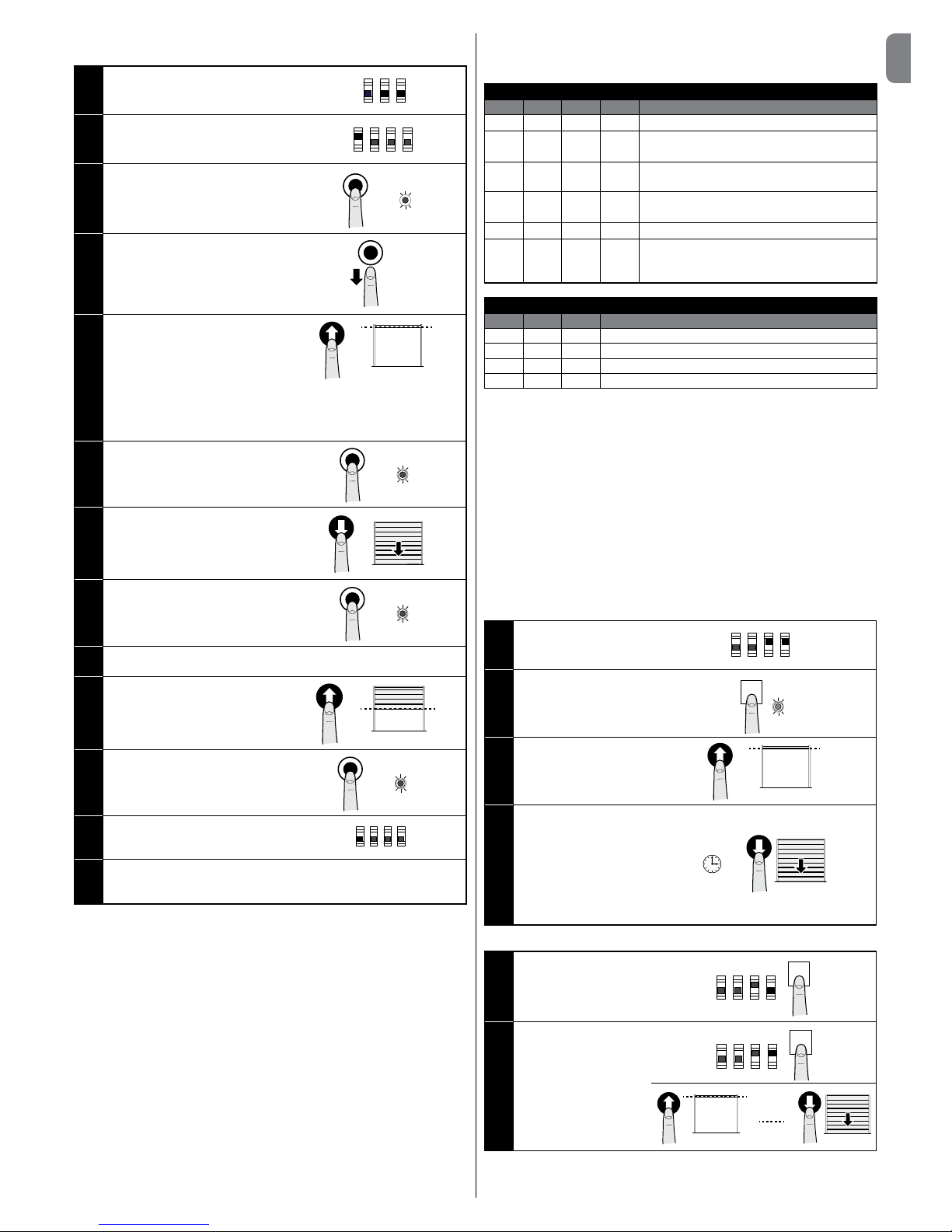
4.5 - Operating modes
CAUTION! - If the functions of Table 3 are programmed with the Oview
programming unit, it is necessary to set the dip switches to OFF.
TABLE 3: DIP SWITCH A
DIP1 DIP2 DIP3 DIP4 Function
OFF OFF OFF OFF
Hold-to-run movement
ON X OFF OFF
Acquisition of positions and status of the ALT
input
OFF ON OFF OFF
Rotation direction of the encoder reversed
(only for absolute encoder)
OFF X OFF ON
Industrial mode (semi-automatic opening –
hold-to-run closing), if positions recognised
OFF X ON OFF
Semi-automatic mode, if positions recognised
OFF X ON ON
Automatic mode with adjustable pause time,
if positions recognised (see para. 4.5.1 “Setting the automatic closing pause time”)
TABLE 4: DIP SWITCH B
DIP1 DIP2 DIP3 Function
OFF X Sensitivity disabled
ON X Sensitivity enabled*
X X OFF Motor with encoder
X X ON Motor with electromechanical limit switch
* Note: the sensitivity parameter allows reducing the door strength of intervention against an obstacle considerably.
During the “Learning about the safety devices” procedure, the control
unit stores the status of dip switches A and B. At the end of this proce-
dure, a variation in the dip switches causes the OK led to ash quickly
with red and green light alternately to highlight the change in conguration; in this phase the control unit allows no commands to be executed.
It is necessary to carry out a new “Learning about the safety devices”
procedure (paragraph 4.3) or press the P1 button for 2 seconds.
Once the positions have been acquired, it is necessary to perform 4
complete manoeuvres to get the control unit to store the force required
to move the door; the manoeuvres are represented by the OK led ashing slowly with red and green light alternately.
The “force and sensitivity” parameters can be adjusted with the Oview programmer (accessory).
4.5.1 - Setting the automatic closing pause time
01. Set dip switches A-3
and A-4 to ON
ON
OFF
1 2 3 4
A
02. Press the P1 button for
2 seconds (the OK led
ashes with green light)
P1
OK
2”
03. Send an opening com-
mand to bring the door
to the maximum opening position
04. Once this position is
reached, wait for a time
equal to the desired
automatic closing pause
time and send a closing
command.
The automatic closing
pause time is now
stored
4.5.2 - Modifying the pause time value
01. Set dip switch A-4 to
OFF and conrm with
the P1 button for 2
seconds
ON
OFF
1 2 3 4
A
P1
2”
02. Set dip switch A-4 to
ON and conrm with the
P1 button for 2 seconds
At this point the opening, pause time and
closing sequence must
be repeated.
ON
OFF
1 2 3 4
A
P1
2”
CAUTION! - When dip switch A-4 is set to OFF, the pause time is cancelled.

8 – English
EN
5
TESTING AND COMMISSIONING
The testing and commissioning phases are the most important when creating an automated system in order to ensure maximum safety. The testing procedure
can also be performed as a periodic check of the automation devices.
These phases must be performed by qualied and experienced personnel who must take charge of establishing the tests necessary to verify the solutions adopted in
respect of risks and verify the compliance of the system with applicable standards, legislation and regulations, in particular all requirements of the standard EN 12445
which establishes the test methods for checking automated systems for gates and doors. The additional devices must undergo specic testing, both in terms of their
functions and in terms of their interaction with the control unit; therefore, you need to refer to the instruction manuals for the individual devices.
5.1 - Testing
The sequence of steps to perform for testing, described below, refers to a typical system (Fig. 2):
1 Check that all the instructions in the “Installation warnings” chapter have been rigorously complied with.
2 Release the motor. Check that the door can be manually manoeuvred with a force no greater than 225N.
3 Lock the motor.
4 Using the control devices (transmitter, push button, key switch, etc.), test the Opening, Closing and Stopping of the door, ensuring that the movement of the
door leaves corresponds to specications. Test several times to assess the movement of the door and check for any defects in assembly or adjustment and
for any particular points of friction.
5 Check, one by one, that all the safety devices featured in the system (photocells, sensitive edges, etc.) work properly.
6 If the dangerous situations caused by the movement of the door leaves have been safeguarded against by limiting the impact force, the impact force must be
measured according to the EN 12445 standard.
5.2 - Commissioning
Commissioning can only be performed after obtaining positive results in all the test phases run on the control unit and the other devices (paragraph 5.1). It is
not permissible to execute partial commissioning or to enable use of the system in “makeshift” conditions.
1 Prepare and store the technical documentation for the automated system for at least 10 years. This must include at least: an assembly drawing of the automated
system, a wiring diagram, an analysis of hazards and solutions adopted, a manufacturer’s declaration of conformity of all the devices installed (for the control unit,
use the annexed CE declaration of conformity); a copy of the automation system instruction manual and maintenance schedule.
2 Post a label on the door providing at least the following data: type of automated system, name and address of manufacturer (person responsible for the “com-
missioning”), serial number, year of manufacture and “CE” marking.
3 Post a permanent label or sign near the door detailing the operations for releasing the system and its manual operation
4 Post a permanent label or sign on the door containing this picture (min. height 60 mm).
5 Prepare the declaration of conformity for the automation system and hand it to the owner.
6 Prepare the “Instructions and warnings for the use of the automation system” and hand it to the owner.
7 Prepare the maintenance schedule for the automation system and hand it to the owner; it must include all the instructions regarding maintenance of the indi-
vidual devices.
4.5.3
- Modifying the speed value
It is possible to modify the opening, opening slowdown, closing and closing
slowdown speed using the Oview accessory or the board keys.
01. Set dip switch 2-B to ON =
the OK led ashes quickly with
orange light.
OFF
ON
1 2 3
B
02. Hold down the P1 key until the
end of step 04
P1
03. Send an opening or closing command with the “OPEN” or “CLOSE”
keys according to the speed you wish to change = the door starts to
move
04. • To increase the speed: press the OPEN key repeatedly = each
pressure corresponds to an increase of 5%
Or
• To increase the speed: press the OPEN key repeatedly = each
pressure corresponds to an increase of 5%
05. Release the P1 key.
To order a new manoeuvre,
repeat the procedure from step
02
P1
06. Set dip switch 2-B to OFF =
the OK led ashes regularly with
green light.
OFF
ON
1 2 3
B
Notes
* With key P1 pressed:
- the OK led signals the position of the door:
∙ OK led green: on a normal stroke
∙ OK led red: slowing down
- the control unit excludes the amp meter control.
• At the end of the procedure, the control unit must go through the procedure
about self-learning the forces (5 complete cycles; the door stops in the closing
position. During the manoeuvres, the OK led ashes red and green alternately).
• With dip switch 2-B, it is possible to control the manoeuvres only as
described in Table 9.

English – 9
EN
6
FURTHER DETAILS
6.1 - Connecting photocells and accessories in standby mode
The “Total stand by” function is used to reduce consumption and is useful when there is a buffer battery because it allows prolonging the battery charge, it can
be activated using the Oview programmer.
Once the “Stand by Time” from the end of a manoeuvre has elapsed (default: 1 minute), the control unit goes into “Total stand by” mode, and switches all inputs
and outputs off to reduce consumption. The state is highlighted by the OK led starting to ash more slowly.
To reduce consumption, it is necessary to connect the photocells and any external devices as shown on the side.
The supply of both transmitters and receivers must be connected to the COM SBY output: in this mode, no Phototest is performed.
WARNING - With the “Stand by” mode active, the control unit can be reactivated by sending a command to the OXI radio receiver or SbS input using the
opening and closing buttons on the box lid.
CAUTION! - If the Photo or Photo2 photocells are not used, jumper the input with the COM SBY output.
COM SBY
TX
1 2
RX
24V …
—
24V …
—
24V …
—
24V …
—
24V …—24V …
—
21 543
TX
1 2
RX
21 543
6.2 - Connecting photocells in “Phototest” mode
The “Phototest” function increases the reliability of the safety devices, allowing reaching “category II” in compliance with the EN 13849-1 standard (set of the
control unit and safety photocells).
When a manoeuvre starts, the safety devices involved in the manoeuvre are checked and the manoeuvre starts only if everything is OK. If the test result is
negative (e.g. photocell blinded by the sun, cables shortcircuited, etc.), the fault is identied and the manoeuvre is not performed.
After the connection in “Phototest” mode, it is necessary to carry out the “Learning about the safety devices and dip switch programming” procedure (paragraph 4.3).
To add a pair of photocells, connect them as follows:
The supply of the receivers is taken directly from the service outputs (terminals GND (1) - 24V, (2)), while the transmitters are supplied from the “Phototest”
output (terminals GND (1) - Phototest (3)). The maximum usable power on the “Phototest” output is 200mA.
CAUTION!
- If two pairs of photocells are used and they interfere with each other, activate the “synchronisation” function as described in the photocell
user manual.
- If photocells Photo or Photo2 are not used, it is necessary to jumper the input with the Phototest output.
TX
1 2
RX
21 543
TX
1 2
RX
21 543
FUSE
FUSE
PHOTO 2
24V …
—
24V …
0V
0V
0V
0V
—
24V …
—
24V …
—
24V …—24V …
—
PHOTO
Common
COM SBY

10 – English
EN
7
DIAGNOSTICS
7.1 - Messages on turning on
When the control unit is switched on, the behaviour of the OK led is signicant as shown in Table 5, in particular:
- if learning the opening and closing positions is correct
- if learning the safety device ( sensitive edge) is correct and what type of device has been recognized..
TABLE 5
Signal when the control unit is switched on Behaviour of the OK led
Clear memory (no position or safety acquired) Quick ashing for 5 seconds - green
Positions acquired and STOP 8.2KΩ 1 slow ash - red
Positions acquired and STOP OSE 2 slow ashes - red
Motor with electromechanical limit switch 1 slow ash - green
Motor with incremental encoder 2 slow ashes - green
Motor with absolute encoder 3 slow ashes - green
After the messages shown in Table 5, the control unit shows any errors: see paragraph 7.2.
6.3 - Connecting a buffer battery
The control unit is prepared for the installation of the buffer battery mod. PS224 (optional accessory): 7.2 Ah with built-in battery
charger.
To connect the buffer battery, proceed as shown on the side.
CAUTION! - The electrical connection of the buffer battery
to the control unit must be done only after completing all the
installation and programming phases, since the battery is an
emergency supply.
6.4 - Connecting the status light and diagnostics
The control unit is ready for the connection of a 24 V - 5 W max
warning light to the “light” terminal of the button panel board inside
the box lid (picture on the side: terminal 1 - 2+).
The “light” can be installed on the same box lid making a hole or out
of the control unit at a maximum distance of 2 m from it.
WARNING - The output is not protected against shortcircuits.
This “light” works as follows:
- OFF = when the safety chain is open (ing ALT, STOP button, red
or release)
- ashing (0.5 s ON, 0.5 s OFF) = when it works correctly
- behaviour as the diagnostics of the OK led, red = when some
components require diagnostics.
1 2
-
+
6.5 - Open and Close block (using the buttons on the
box lid)
In the button panel board inside the box lid, there is a two-way dip
switch that allows activating the Open and Close buttons.
- OFF position = the buttons are disabled.
- ON posi
tion = the buttons are enabled.
WARN
ING - The STOP button is always active.
WARNING - To perform the learning procedures, the dip
switches must be activated to be able to use the buttons.
ON
OFF

English – 11
EN
7.2 - Diagnostics
Some devices are supposed to issue warnings that allow identifying their status or any faults.
Table 6 describes the various messages with their relative causes and solutions; the warnings are based on combinations of colours, OK led ashing and a
possible, suitably programmed, asher connected to the outputs of the control unit.
TABLE 6: OK LED SIGNALS (ashing red)
Signal Cause Solution
2 ashes - 1 sec. pause
2 ashes - red led
Triggering of a photocell At the beginning of the manoeuvre, one or more photocells are preventing movement;
check if there are any obstacles.
During the closing movement it is normal if an obstacle is present.
3 ashes - 1 sec. pause
3 ashes - red led
Intervention of the “Driving
Force” or “Sensitivity” or
“Blocked Encode” limiter
While moving, the door has met with increased friction: check its cause.
4 ashes - 1 sec. pause
4 ashes - red led
Activation of the STOP input At the start of the manoeuvre or during the movement, the STOP ALT input has been trig-
gered or the motor release lever has been activated: check the cause.
5 ashes - 1 sec. pause
5 ashes - red led
Internal parameter memorisation
error
Press the STOP button on the box lid to reset the error.
Wait for at least 30 seconds to allow the control unit to reset. If the situation does not
change, it is necessary to delete the memory and carry out the storing procedure again.
6 ashes - 1 sec. pause
6 ashes - red led
Maximum limit of manoeuvres
per hour exceeded
Wait for a few minutes to allow the manoeuvre limiter to go back below the maximum.
7 ashes - 1 sec. pause
7 ashes - red led
Error in the internal electrical
circuits
Press the STOP button on the box lid to reset the error.
Disconnect all the supply circuits for a few seconds, then try and send a command again;
if the situation does not change there may be a serious fault on the board or on the motor
wiring: check and replace as required.
8 ashes - 1 sec. pause
8 ashes - red led
Command already present Another command is already present.
Remove the command to be able to send more.
9 ashes - 1 sec. pause
9 ashes - red led
Automation blocked Send an automation unlocking command to reset normal operation.
Note – The diagnostic signals provided by ashing LEDs stop when the control unit is given a command.
By using an external ashing light*, the diagnostics signals continue for two sequences of ashes (e.g. “3 ashes – short pause – 3 ashes – long
pause” repeated twice).
* Congured with the Oview programmer as “Flashing Light 1”
TABLE 7: OK LED SIGNALS (red light ON - green ashing)
Signal Cause Solution
Red light on
8 ashes - 1 sec. pause
8 ashes - green led
Encoder error.
No signal
Press the STOP button on the box lid to reset the error.
Check if the encoder cable has detached.
Red light on
10 ashes - 1 sec. pause
10 ashes - green led
Manoeuvre timeout.
The duration of the manoeuvre
has exceeded the one stored
during the learning phases
Press the STOP button on the box lid to reset the error.
If necessary, repeat learning the positions or change the value of the manoeuvre Time,
using the Oview programmer.
TABLE 8: OK LED SIGNALS (ashing red and green)
Signal Cause Solution
Alternate red - green ashing Dip switch conguration modied Check the conguration and, if correct, conrm keeping the P1 button pressed for 2 sec-
onds
Red a nd green alternate
ashing during the manoeuvre
Force learning in progress Carry our 4 complete manoeuvres to perform the learning of the forces required for handling.
Caution: during this phase the control unit uses maximum force.
TABLE 9: OK LED SIGNALS (ashing orange)
Signal Cause Solution
Fast orange ashing Dip switch 2-B on ON Modify the speed with the “OPEN” / “CLOSE” keys and set dip switch 2-B to OFF
8
DISPOSAL OF THE PRODUCT
This product is an integral part of the automation system, therefore it must be disposed of along with it.
As in installation, also at the end of product lifetime, the disassembly and scrapping operations must be performed by qualied personnel.
This product is made up of different types of material, some of which can be recycled while others must be disposed of. Seek information on
the recycling and disposal systems envisaged by the local regulations in your area for this product category.
Caution! – Some parts of the product may contain pollutants or hazardous substances which, if released into the environment, may cause
serious damage to the environment or human health.
As indicated by the symbol on the left, disposal of this product in domestic waste is strictly prohibited. Separate the waste into categories for
disposal, according to the methods envisaged by current legislation in your area, or return the product to the retailer when purchasing a new
version.
Caution! – Local legislation may envisage serious nes in the event of abusive disposal of this product.
12 – English
EN
9
TECHNICAL SPECIFICATIONS OF THE PRODUCT
WARNINGS: • All technical specications stated herein refer to an ambient temperature of 20° C (± 5° C). • Nice S.p.A. reserves the right to apply modications
to products at any time when deemed necessary, maintaining the same intended use and functionality.
DPRO924 supply 230V~50/60Hz
DPRO924/V1 supply 120V~50/60Hz
Maximum power absorbed by the
network
500W
Class of insulation 1 (a safety grounding system is required)
Emergency supply With accessory PS224
Service output 24V
-30/+50%, 200mA
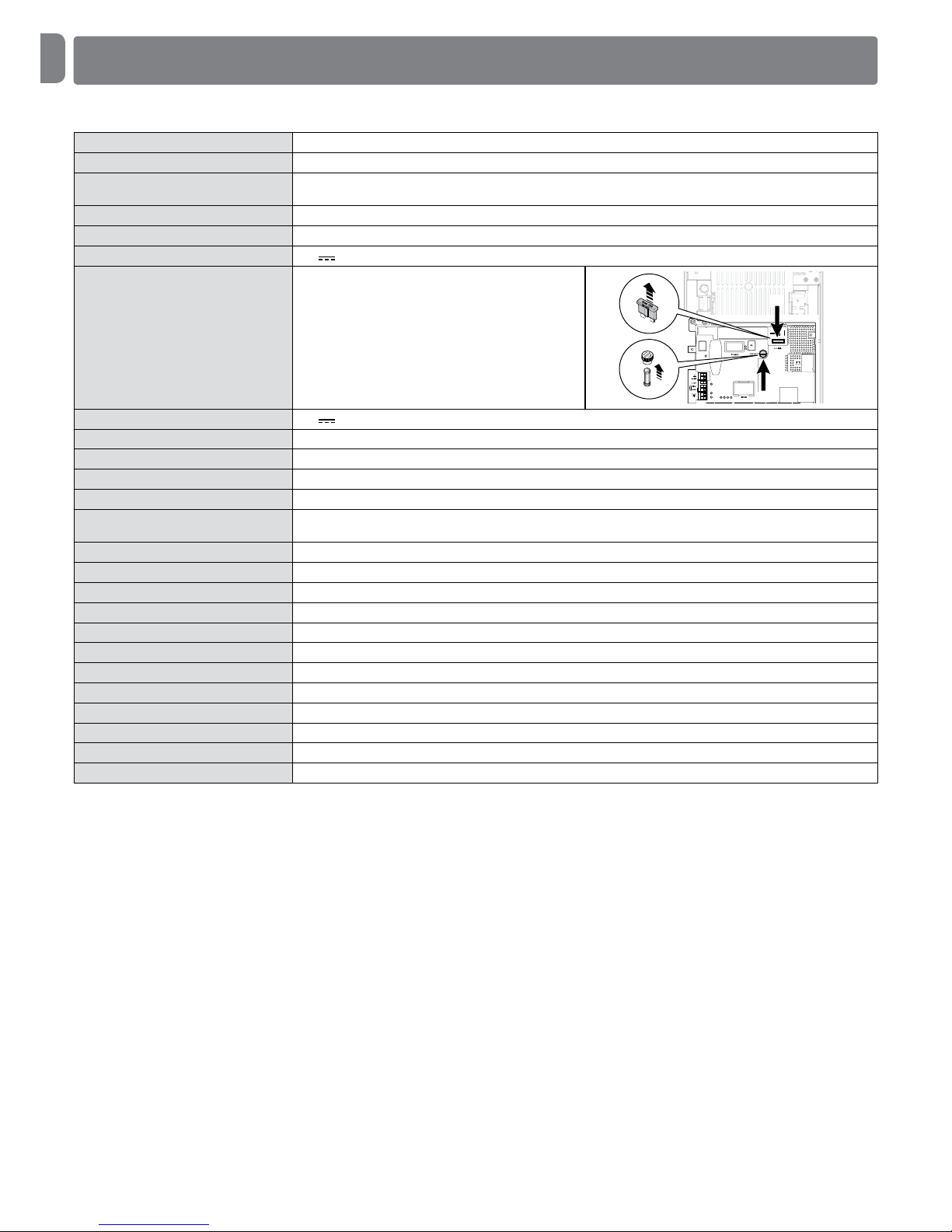
Board fuses F2: 2A type T
F1: 20A type auto
FUSE
FUSE
F2
F1
Phototest outlet 24V , maximum current 200mA
OUT1 output For 1 asher ELDC, programmable with Oview
OUT2 output With clean contact (relay), programmable with Oview
OUT3 output With clean contact (relay), programmable with Oview
Aerial input 52ohm for RG58-type cable or similar - for OXI New Generetion use the aerial connector on the receiver
STOP input For contacts with 8.2 Ω constant resistance or OSE optical type; in self-learning (a variation from the stored status
triggers the “STOP” command)
ALT input For Normally Closed (NC) contacts in the safety circuit
SbS input For Normally Open (NO) contacts, Programmable with Oview
Open input For Normally Open (NO) contacts, Programmable with Oview
Close input For Normally Open (NO) contacts, Programmable with Oview
Photo input For Normally Closed (NC) contacts
Photo2 input For Normally Closed (NC) contacts
Radio coupling SM connector for SMXI, OXI, OXI New Generetion, OXIBD receivers
IBT4N coupling For IBT4N accessory for Oview connection or IT4WiFi
Operating temperature -20°C ... +55°C
Protection class IP55 with container undamaged
Dimensions 310 x 210 x 125 mm
Weight About 4 kg

English – 13
EN
EU Declaration of Conformity (N.635/DPRO924)
and declaration of incorporation of “partly completed machinery”
Note: the contents of this declaration correspond to that stated in the official document filed in the offices of Nice S.p.A. and, in particular,
the latest version thereof available prior to the printing of this manual. The text herein has been re-edited for editorial purposes. A copy of
the original declaration can be requested from Nice S.p.A. (TV) Italy.
Revision: 0 Language: EN
Manufacturer’s name: NICE S.p.A. Product type: Control unit for 1 24Vdc motor
Address: via Callalta n.1, 31046 Oderzo (TV) Italy Model / Type: DPRO924
Person authorised to compile the technical documentation:
NICE S.p.A.
Accessories: Refer to the catalog
Address: via Callalta n.1, 31046 Oderzo (TV) Italy
The undersigned, Roberto Griffa, as Chief Executive Officer, hereby declares under his own responsibility that the product identified above
complies with the provisions of the following directives:
• Directive 2014/30/UE (EMC) EN 61000-6-2:2005 - EN 61000-6-3:2007+A1:2011
In addition, the product conforms to the following directive in accordance with the provisions applicable to “partly completed machinery”:
(Annex II, part 1, section B):
• In addition, the product conforms to the following directive in accordance with the provisions applicable to “partly completed machinery”:
Directive 2006/42/EC OF THE EUROPEAN PARLIAMENT AND COUNCIL of May 17 2006 regarding machines and amending Directive
95/16/EC (consolidated text).
- It is hereby declared that the relevant technical documentation has been compiled in accordance with Annex VII Part B of Directive
2006/42/EC and that the following essential requirements have been applied and fullled: 1.1.1- 1.1.2- 1.1.3- 1.2.1-1.2.6- 1.5.1-1.5.2-
1.5.5- 1.5.6- 1.5.7- 1.5.8- 1.5.10- 1.5.11
- The manufacturer agrees to transmit to the national authorities any pertinent information on “partly completed machinery”, in response
to a motivated request, without prejudice to its intellectual property rights.
- Should the “partly completed machinery” be commissioned in a European country with an ofcial language different to the one used in
this declaration, a translation into that language accompanying this declaration must be provided by the importer.
- The “partly completed machinery” may not be commissioned until the nal machinery into which it is to be incorporated has been decl
red to conform to the provisions of Directive 2006/42/EC, where appropriate.
The product also complies with the following standards: EN 60335-1:2012+A11:2014, EN 62233:2008, EN 60335-2-103:2015
Place and Date: Oderzo, 30/03/2018 Ing. Roberto Griffa (Chief Executive Ofcer)

www.niceforyou.com
Nice SpA
Via Callalta, 1
31046 Oderzo (TV) Italy
info@niceforyou.com
IS0662A00MM_31-07-2018
 Loading...