

Page 1
AHEAD OF THE FLOW
AHEAD OF THE FLOW
®
®
Installation and Maintenance Guide
for
NIBCO Butterfly Valves with Rubber Seats
www.nibco.com
www.nibco.com
Revised 06/03/2009
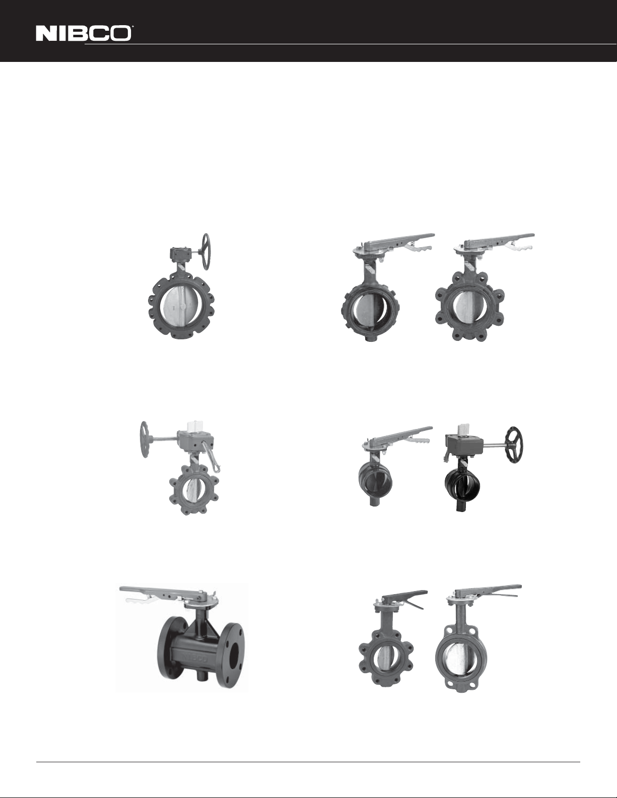
LD1000/2000/7000/8000 Series LD/WD2000/3000/5000 Series
LC/WC2000 Series
LD/WD3500 Series
GD4700 Series
FC/FD2000 Series
N200 Series
FC/FD5000 Series
BFVMAN-0609 © 2009, NIBCO INC. www.nibco.com printed in USA
Page 2

www.nibco.com
AHEAD OF THE FLOW
®
Revised 06/03/2009
INSTALLATION GUIDE FOR NIBCO BUTTERFLY VALVES
I. SHIPMENT & STORAGE
NIBCO butterfly valves are individually boxed thru the 12" size. The 14" through 60" butterfly valves are shipped individually with the
faces covered using cardboard or plywood to protect the flange sealing surfaces.
The disc is shipped in the nearly closed position to protect the sealing edge and prevents the liner from taking a temporary set. The
stem bushings and disc edge have been coated with a factory-applied lubricant to prolong storage and service life.
Valves may be shipped or stored in any position. Storage should be limited to 10 years indoors with a temperature range of 40º F to
90º F.
II. BUTTERFLY VALVE INSTALLATION GUIDELINES
NIBCO butterfly valves are bi-directional and may be installed with flow in either direction.
Flanged, lug and wafer style valves are designed and suitable for installation between ANSI Class 125 or 150 flanges. Cast iron flat-
face, steel raised-face, both slip-on and weld-neck, and bronze or plastic flanges may be used (See Table I below). Generally raised
face flanges should not be used with cast iron lug style valves (NIBCO N2002 and LC2000 series valves). Because of the unique seat
design, NIBCO (2"-48") butterfly valves do not require the use of flange gaskets and can be used for dead end service without a downstream flange. Grooved style valves connect to metallic pipe of IPS per AWWA C606.
The valve can be installed in any horizontal or vertical position. If a choice of stem positions exists, the valve should be installed with
the stem in the horizontal position; this will minimize seat wear by distributing the stem and disc weight evenly. Also, if the media is
abrasive, the horizontal stem position is highly preferred.
These valves have been designed so that the disc, in the open position, will clear the inside diameter of schedule 40 and 80 steel pipe.
Care should be taken when installing a butterfly valve adjacent to lined pipe, as-cast fittings, or schedule 80 plastic pipe. In some
cases the disc in the opened position will interfere with the adjacent component.
Butterfly valves should be installed a minimum of six (6) pipe diameters from other line components. This is not always practical
but it is important to design in as much distance as possible. Interference may occur when valves are installed directly to the outlet
flange of a swing check, silent check, or reducing flange. Check valve and butterfly valve combinations are very popular; normally a
short spool piece is required between the valves.
2
NIBCO INC. WORLD HEADQUARTERS • 1516 MIDDLEBURY ST. • ELKHART, IN 46516-4740 • USA • PH: 1.800.234.0227
TECH SERVICES PH: 1.888.446.4226 • FAX: 1.888.234.0557 • INTERNATIONAL OFFICE PH: +1.574.295.3327 • FAX: +1.574.295.3455
www.nibco.com
Page 3
www.nibco.com
AHEAD OF THE FLOW
®
Revised 06/03/2009
II. BUTTERFLY VALVE INSTALLATION GUIDELINES cont.
When using a valve with gear operator attached, it may be desirable to have the hand wheel positioned to allow easy access, or for
use of an optional adjustable sprocket rim (chain wheel) for remote operation. Before valve installation, please review Gear Operator
Installation and Handwheel Positioning section on page 3 of this booklet. These instructions illustrate how to orient the gear operator
handwheel position in relation to the valve body and piping system. Pre-planning may save from having to remove a "just installed"
valve and re-installing in another orientation.
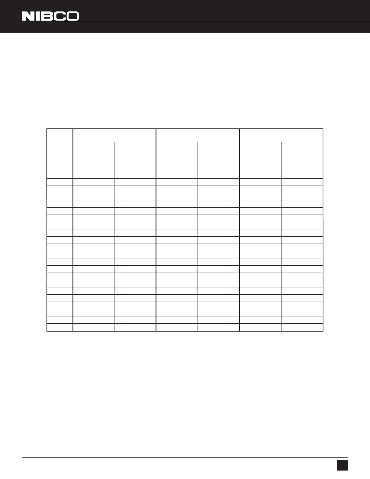
TABLE I
Piping/Flange Inside Diameter Requirements
Valve LD/WD/LC/WC
Series 1000/2000/3000/5000
Minimum Maximum Minimum Maximum Minimum Maximum
Valve Pipe/Flange Pipe/Flange Pipe/Flange Pipe/Flange Pipe/Flange Pipe/Flange
Size ID for Disc ID for ID for Disc ID for ID for Disc ID for
Clearance Proper Seal Clearance Proper Seal Clearance Proper Seal
2 2.00 2.49 1.31 2.43 1.38 2.24
21/2 2.37 2.86 1.89 3.06 1.95 2.74
3 2.67 3.43 2.64 3.65 2.66 3.33
4 3.69 4.55 3.67 4.75 3.67 4.55
5 4.76 5.62 4.44 5.54 4.48 5.50
6 5.96 6.62 5.96 6.84 5.96 6.66
8 8.01 8.62 7.85 8.89 7.85 8.61
10 10.00 10.80 9.73 10.70 9.76 10.75
12 11.99 13.12 11.71 12.74 11.72 12.79
14 13.16 13.77 13.02 15.50 — —
16 15.34 16.30 15.20 17.90 — —
18 17.23 18.31 17.16 19.67 — —
20 19.04 20.08 19.10 21.05 — —
24 23.05 24.71 23.04 25.57 — —
28 — — 27.10 29.31 — —
30 29.06 30.29 29.08 31.28 — —
32 — — 30.91 33.93 — —
36 33.59 35.78 33.60 36.77 — —
42 39.83 42.77 39.87 44.96 — —
48 44.85 48.27 44.86 51.57 — —
54 — — 50.67 54.25 — —
60 — — 54.93 60.25 — —
LD7000/8000 Series N200 Series
NIBCO INC. WORLD HEADQUARTERS • 1516 MIDDLEBURY ST. • ELKHART, IN 46516-4740 • USA • PH: 1.800.234.0227
TECH SERVICES PH: 1.888.446.4226 • FAX: 1.888.234.0557 • INTERNATIONAL OFFICE PH: +1.574.295.3327 • FAX: +1.574.295.3455
www.nibco.com
3
Page 4
AHEAD OF THE FLOW
®
Revised 06/03/2009
www.nibco.com
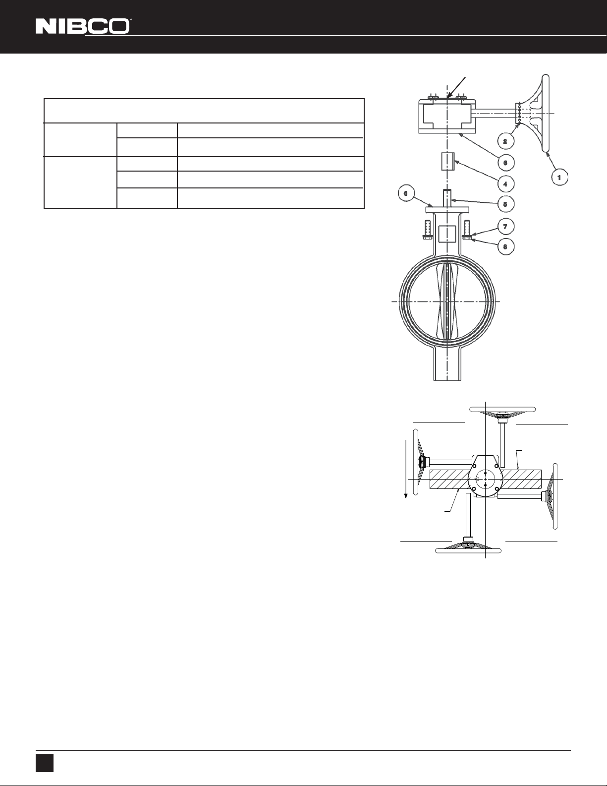
III. GEAR OPERATOR INSTALLATION HANDWHEEL POSITIONING
POINTER COVER PLATE
TABLE 2
Tools Required
Fire Protection 2" — 8" 9/16" hex wrench & 1/8" hex allen wrench
(UL/FM) 10" — 12" 3/4" hex wrench and 1/8" hex allen wrench
2" — 8" 9/16" hex wrench
Commercial 10" — 14" 3/4" hex wrench
1
16" — 18" 1
/8" hex wrench
INSTALLATION
1. Install handwheel (1) onto gear operator shaft and secure with pin (2). (If not
already attached) See Fig. 1.
2. Turn the handwheel (1) clockwise until in full SHUT position.
3. Remove 2 screws holding pointer cover plate to center of gear operator to expose
bore. Retain pointer cover plate and screws for reinstallation later.
4. Assure valve is in full SHUT position, turn valve stem (5) to close disc if
necessary.
5. Assure both mounting base of gear operator (3) and valve top flange (6) are clean
and dry.
6. Determine desired handwheel position in reference to the piping system and
compare with Fig. 2. There are 2 mounting positions for the gear operator onto
the valve and the valve can be mounted in either direction into the piping system.
This will allow handwheel to be positioned in any of the 4 quadrants as shown in
Fig. 2. Note that all Fire Protection and 10" and 12" size commercial valves only
allow for handwheel positioning in quadrants 1 and 2.
Quadrant 1
UPSTREAM PIPING
7a) Gear operators with adapter bushing.
• Insert adapter bushing (4) into gear operator (3) bore aligning bushing key with
desired keyway. Keyway selection will determine handwheel orientation position. (Note that Fire Protection model adapter bushings differ from illustration
and only have 1 keyway position).
• Align adapter bushing (4) bore with valve stem (5) and slide gear operator
assembly onto valve stem (5) until seated with valve top flange.
7b) Gear operators without adapter bushing.
• Align gear operator (3) bore with valve stem (5) and align with desired keyway.
Keyway selection will determine handwheel orientation position.
• Slide gear operator assembly onto valve stem (5) until seated with valve top
flange.
FLOW DIRECTION
Valve Side A
Quadrant 3
DOWNSTREAM PIPING
8. Secure gear operator (3) to valve top flange (6) using supplied* fasteners (7 & 8).
9. Reinstall pointer cover plate onto gear operator removed in step 3 above. Arrow should be aligned to indicate SHUT positon.
10. Install flag and secure with Allen Screw. (Fire Protection gear operators only.)
11. Rotate handwheel from full SHUT to Full OPEN positions several times to assure proper operation. See Stop Adjustment
Procedure Section of this instruction booklet on page 5 if stop alignment adjustment is necessary.
12. Proceed with valve installation into piping system.
For Fire Protection, gear operators, it is critical to use only the key supplied with gear operator in order to conform to UL, FM and ULC
specifications.
NOTE: Connection of gear operator to valve stem varies depending on gear operator model, size and style. The adapter
bushing and key may be different from illustration shown.
*A minimum of two fasteners is required, installed in opposite diagonal corners.
Fig. 1
Quadrant 4
Valve Side B
Quadrant 2
Fig. 2
4
NIBCO INC. WORLD HEADQUARTERS • 1516 MIDDLEBURY ST. • ELKHART, IN 46516-4740 • USA • PH: 1.800.234.0227
TECH SERVICES PH: 1.888.446.4226 • FAX: 1.888.234.0557 • INTERNATIONAL OFFICE PH: +1.574.295.3327 • FAX: +1.574.295.3455
www.nibco.com
Page 5
www.nibco.com
AHEAD OF THE FLOW
®
Revised 06/03/2009
IV. VALVE INSTALLATION PROCEDURE - FLANGE, LUG & WAFER STYLE ONLY
Always position the connecting pipe flanges accurately in the line, allowing sufficient space between the flanges for the valve. Make
sure the pipe flange faces are clean of any foreign material such as scale, metal shavings or welding slag. Valves should be installed
with the disc in the closed position to prevent damage to sealing surfaces.
1. Carefully insert the valve between the pipe flanges. Do not apply any lubricants to the seat faces as this may damage them.
2. Line up, center and secure the valve between flanges using desired bolts or studs as listed in Table 4 on next page.
Do not tighten bolts at this time.
3. Carefully open the valve to assure free unobstructed disc movement. Disc interference may result when valves are installed in
pipelines having smaller than normal inside diameters, such as heavy wall pipe, plastic-lined pipe, as-cast flanges or reducing
flanges. Interference can also occur when connecting directly to a swing check or silent check. Suitable corrective measures must
be taken to remove these obstructions, such as taper boring the pipe or installing a spacer or spool piece.
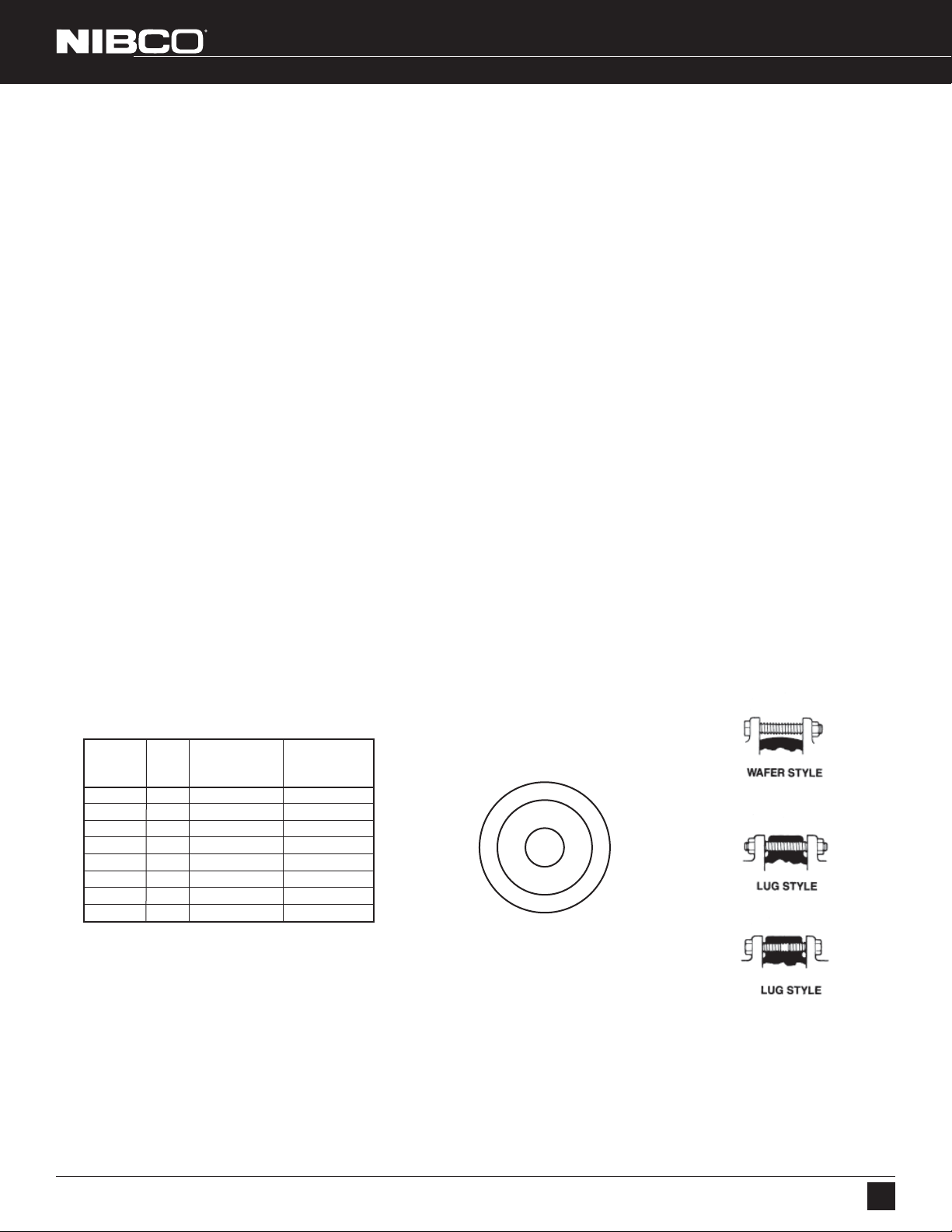
4. After proper operation is verified, tighten the bolts to the minimum recommended bolt torques listed in Table 3 below using a
cross-over pattern, also shown below in Figure 3. NOTE: When installing valves NPS 14" and larger between two flanges, it is
recommended that the cartridge liner be evely compressed from both sides of the mating flanges. NIBCO recommends a
multi-stepped process utilizing the cross-over pattern be used to draw the flanges against the liner from both sides of the valve
at the same rate, ensuring the liner is compressed evenly. This method differs from the practice used on smaller valves, wherein
one flange side is completely tightened before moving to the opposite side.
5. Pressurize piping to valve and inspect for leakage. If leakage is observed, tighten bolts using
cross-over pattern, increasing torque until leak stops.
DO NOT EXCEED MAXIMUM TORQUES LISTED IN TABLE 3 BELOW.
6. Recommended torques are made without warranty. Installer must verify proper strength bolts
for application. Bolts shall be clean and un-lubricated.
Caution
1. Class 250 cast iron and Class 300 steel flanges can not be used on these valves.
2. Rubber faced or mechanical flanges are not recommended.
3. This valve is not recommended for steam service.
4. Valves should not be assembled to the flanges and then welded into the piping system.
5. Lever-lock handles are not recommended for use on 8" and larger valves.
6. Do not install valves with EPDM liner in compressed air lines.
Table 3 Recommended Bolt Tightening Torques
Fig. 3
Bolt Tightening
Flange Bolt Minimum Bolt Maximum Bolt
Size Size Torque (ft.•lbs.) Torque (ft.•lbs.)
2" - 4" 5/8" 20 70
5" - 8" 3/4" 30 120
10" & 12" 7/8" 50 200
14" & 16" 1" 70 240
18" & 20" 1
24" - 30" 1
32" - 48" 11/2" 200 800
54" - 60" 1
1
/8" 100 380
1
/4" 140 520
3
/4" 350 1800
Cross Over Pattern
1
5
3
7
2
Suggested
Bolting Methods
8
4
6
NIBCO INC. WORLD HEADQUARTERS • 1516 MIDDLEBURY ST. • ELKHART, IN 46516-4740 • USA • PH: 1.800.234.0227
TECH SERVICES PH: 1.888.446.4226 • FAX: 1.888.234.0557 • INTERNATIONAL OFFICE PH: +1.574.295.3327 • FAX: +1.574.295.3455
www.nibco.com
5
Page 6
AHEAD OF THE FLOW
®
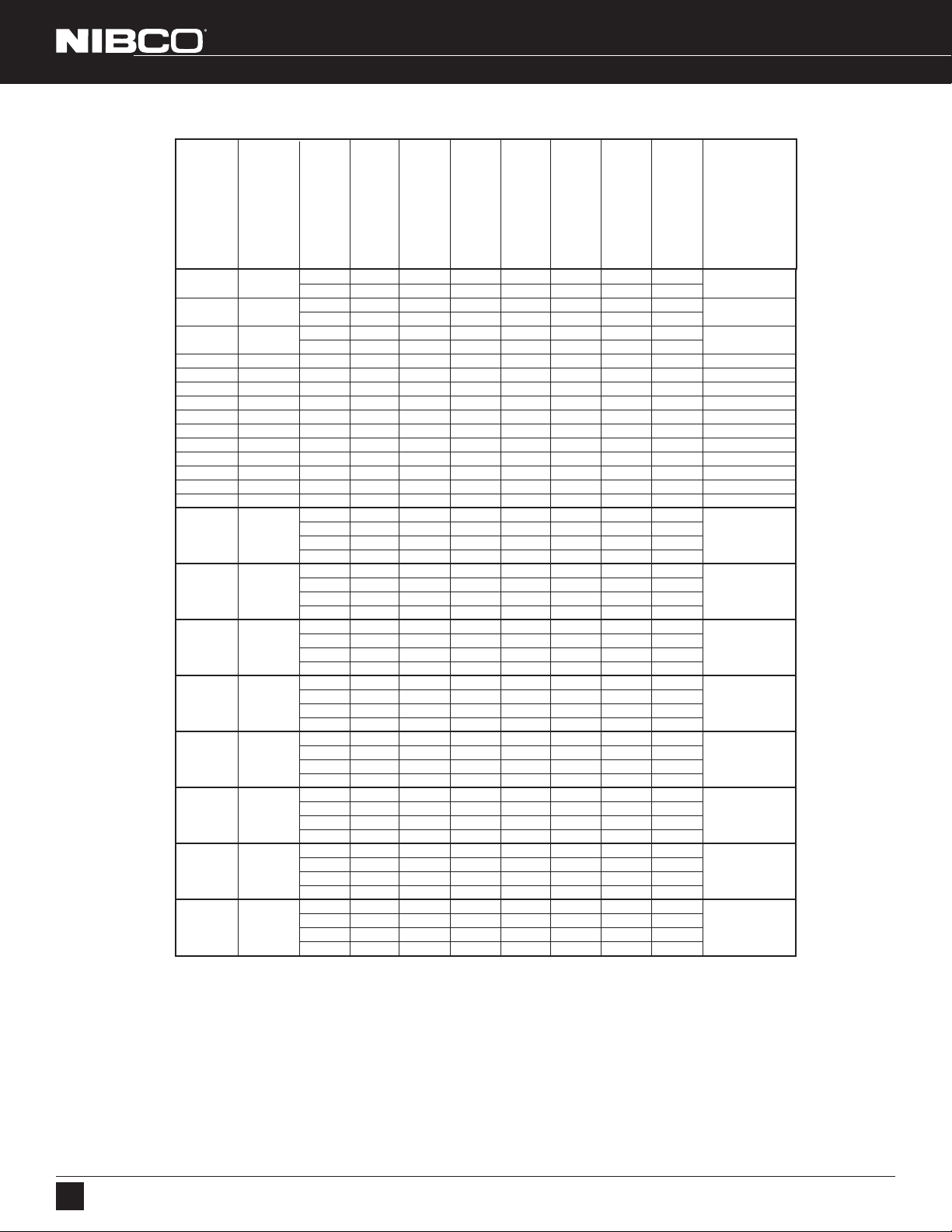
Table 4 Recommended Bolt Lengths
www.nibco.com
Revised 06/03/2009
VALVE SIZE
SERIES ONLY
1000/2000/3000
2" 1.69
— 0.75 — — — 1.50 4.00 8/4
2 1/2" 1.81
— 0.88 — — — 1.75 5.00 8/4
3" 1.81
— 0.94 — — — 1.75 5.00 8/4
TOTAL VALVE
ANSI B16.1
BODY WIDTH
0.63 — — — — 1.25 4.00 8/4
0.69 — — — — 1.50 5.00 8/4
0.75 — — — — 1.50 5.00 8/4
ANSI B16.5
CLASS 150 STEEL
FLANGE THICKNESS
CLASS 125 CAST IRON
FLANGE THICKNESS
MSS SP-44
CLASS 150 STEEL
ANSI B16.47 (SERIES A)
WELD NECK
CLASS 150 STEEL
FLANGE THICKNESS
ANSI B16.47 (SERIES B)
BLIND STYLE
CLASS 150 STEEL
FLANGE THICKNESS
FLANGE THICKNESS
ANSI B16.47 (SERIES B)
RECOMMENDED
RECOMMENDED
(LUGGED VALVES)
CAP SCREW LENGTH
BOLT LENGTH
(WAFER VALVES)
TOTAL QUANTITY
CAP SCREWS/BOLTS
(TO MOUNT 2 FLANGES)
5/8-11 UNC
5/8-11 UNC
5/8-11 UNC
CAP SCREW SIZE
4" 2.06 0.94 0.94 — — — 1.75 5.00 16/8 5/8-11 UNC
5" 2.19 0.94 0.94 — — — 1.75 5.00 16/8 3/4-10 UNC
6" 2.19 1.00 1.00 — — — 2.00 6.00 16/8 3/4-10 UNC
8" 2.38 1.12 1.12 — — — 2.25 6.00 16/8 3/4-10 UNC
10" 2.69 1.19 1.19 — — — 2.25 7.00 24/12 7/8-9 UNC
12" 3.00 1.25 1.25 — — — 2.50 7.00 24/12 7/8-9 UNC
14" 3.01 1.38 1.38 — — — 2.50 7.00 24/12 1-8 UNC
16" 3.38 1.44 1.44 — — — 3.00 8.00 32/16 1-8 UNC
18" 4.12 1.56 1.56 — — — 3.00 9.00 32/16 1
20" 5.14 1.69 1.69 — — — 3.50 10.00 40/20 1
24" 5.98 1.88 1.88 — — — 4.00 11.00 40/20 1
1
/8
1
/8
1
/4
-7 UNC
-7 UNC
-7 UNC
— — — — — — — 56
28" 6.42
— — — — 1.88 4.00 — 56
— — — 1.75 — 4.00 — 56
1
1
/4
-7 UNC
— — 2.81 — — 5.00 — 56
2.12 — — — — 3.50 — 56
30" 6.57
— — — — 2.00 3.50 — 56
— — — 1.75 — 3.00 — 56
1
1
/4
-7 UNC
— — 2.94 — — 4.25 — 56
— — — — — — — 56
32" 7.40
— — — — 2.13 4.00 — 56
— — — 1.81 — 4.00 — 56
1
1
/2
-6 UNC
— — 3.91 — — 5.00 — 56
2.38 — — — — 4.00 — 64
36" 8.00
— — — — 2.31 4.00 — 64
— — — 2.06 — 3.50 — 64
1
1
/2
-6 UNC
— — 3.56 — — 5.00 — 64
2.62 — — — — 4.50 — 72
42" 9.88
— — — — 2.69 4.50 — 72
— — — 2.31 — 4.00 — 72
1
1
/2
-6 UNC
— — 3.81 — — 5.50 — 72
2.75 — — — — 4.50 — 88
48" 10.87
— — — — 3.06 5.00 — 88
— — — 2.56 — 4.50 — 88
1
1
/2
-6 UNC
— — 4.25 — — 6.00 — 88
3.00 — — — — 7.00 — 88
54" 15.00
— — — — 3.44 7.50 — 88
— — — 2.81 — 7.00 — 88
3
1
/4
-5 UNC
— — 4.75 — — 8.50 — 88
3.12 — — — — 7.00 — 104
60" 15.00
— — — — 3.81 8.00 — 104
— — — 3.00 — 7.00 — 104
3
1
/4
-5 UNC
— — 5.19 — — 9.00 — 104
6
NIBCO INC. WORLD HEADQUARTERS • 1516 MIDDLEBURY ST. • ELKHART, IN 46516-4740 • USA • PH: 1.800.234.0227
TECH SERVICES PH: 1.888.446.4226 • FAX: 1.888.234.0557 • INTERNATIONAL OFFICE PH: +1.574.295.3327 • FAX: +1.574.295.3455
www.nibco.com
Page 7
AHEAD OF THE FLOW
®
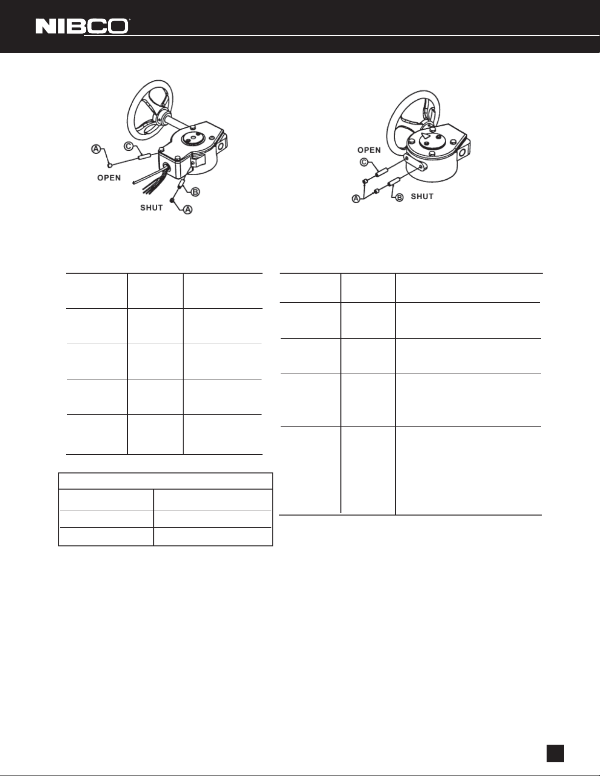
BUTTERFLY VALVE GEAR OPERATOR SETTING INSTRUCTIONS
Fig. 7 Fig. 8
www.nibco.com
Revised 06/03/2009
2" - 12"
UL/FM Valve Gear Operator
Part Valve
Number Size Valve Series
T117166 PP
2
T117167 PP
4" — 6" GD-4765
T117890 PP
8" GD-4765
T117168 PP
10" GD-4765
2" — 4" WD/LD 3510
1
/2" — 3" GD-4765
5" — 6" WD/LD 3510
8" WD/LD 3510
10" — 12" WD/LD 3510
Table 5
Tools Required
2" — 8" valves 4mm or 5mm hex allen wrench
10" — 18" valves 6mm hex allen wrench
20" — 24" valves 8mm hex allen wrench
2" - 24"
Commercial Valve Gear Operator
Part Valve
Number Size Valve Series
T117118 PP
2" — 5" FC/FD/GD 2000/5000/4000
T117119 PP
6" — 8" FC/FD/GD 2000/5000/4000
T117120 PP 10" WD/LD 2000/3000
T117121 PP
10" — 12" FC/FD/GD 2000/5000/4000
T116697 PP 14"
T026150 PP 16"
T026151 PP 18" LD 1000
T026211 PP 20"
T026212 PP 24"
2" — 6" WD/LD 2000/3000
8" WD/LD 2000/3000
12" WD/LD 2000/3000
V. STOP ADJUSTMENT PROCEDURE
1. With valve in closed position, mount gear operator onto body.
2. Remove 2 lockscrews (A) from gear operator body.
3. Turn shut stop screw (B) clockwise until snug.
4. Open valve by turning handwheel until valve disc is in fully open position.
5. Turn open stop screw (C) clockwise until snug.
6. Close valve by turning handwheel until valve is in the fully closed position.
7. Inspect valve to be sure disc returned to a fully closed position with disc centered in the seat area. Readjust shut stop
screw (B) if necessary.
8. Reinstall 2 lockscrews (A) into gear operator body to lock stops in position.
NOTE: The gear operator’s OPEN position has been set at time of shipping. These instructions should be used for slight
adjustment as needed.
NIBCO INC. WORLD HEADQUARTERS • 1516 MIDDLEBURY ST. • ELKHART, IN 46516-4740 • USA • PH: 1.800.234.0227
TECH SERVICES PH: 1.888.446.4226 • FAX: 1.888.234.0557 • INTERNATIONAL OFFICE PH: +1.574.295.3327 • FAX: +1.574.295.3455
www.nibco.com
7
Page 8
AHEAD OF THE FLOW
®
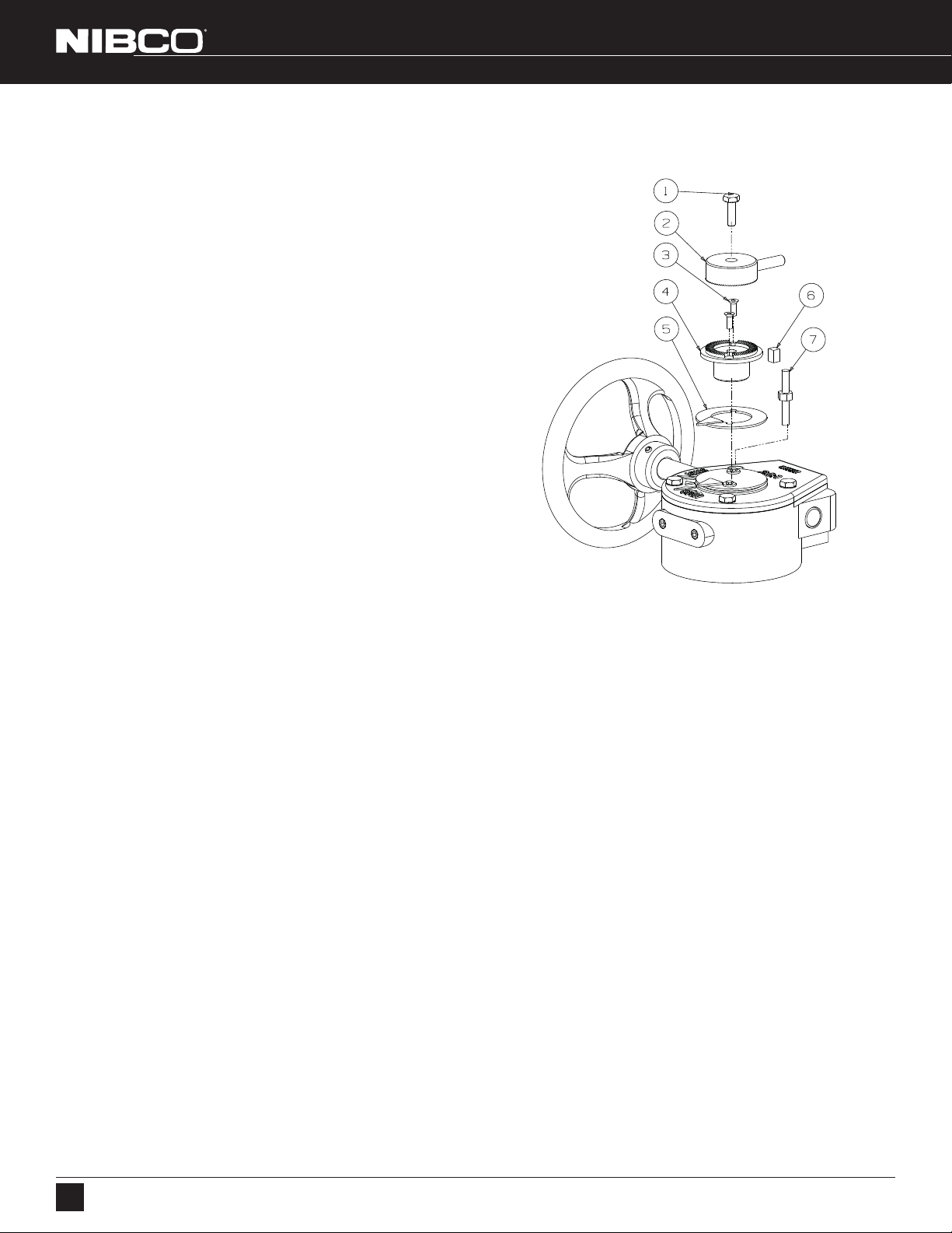
VI. MEMORY STOP INSTALLATION INSTRUCTION - 2" THRU 24" SIZE VALVES ONLY
1. Remove the two screws holding the top cover (Indicator
Pointer) on to segment gear. Discard cover and screws
2. Place indicator (5) supplied with kit around bottom hub (4) and
align key (6) on bottom hub with slot in segment gear and slide
into place.
3. Attach with two M4 x 12 flat head screws (3).
4. Remove one capscrew (1) holding cover onto gear operator
housing and replace with stop pin (7).
5. Use capscrew (1) secure the top hub (2) to the bottom hub (4).
Top hub can be moved 360 degrees in 5 degree increments.
6. Tighten capscrew (1) once top hub is appropriately set.
www.nibco.com
Revised 06/03/2009
Fig. 9
8
NIBCO INC. WORLD HEADQUARTERS • 1516 MIDDLEBURY ST. • ELKHART, IN 46516-4740 • USA • PH: 1.800.234.0227
TECH SERVICES PH: 1.888.446.4226 • FAX: 1.888.234.0557 • INTERNATIONAL OFFICE PH: +1.574.295.3327 • FAX: +1.574.295.3455
www.nibco.com
Page 9
AHEAD OF THE FLOW
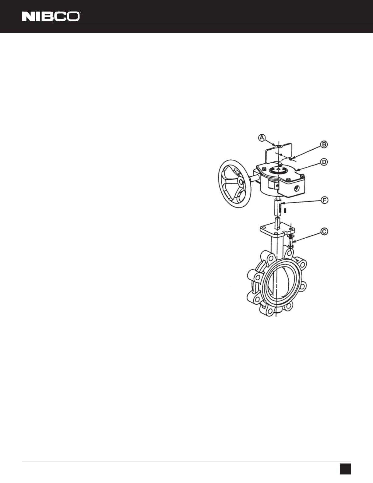
VII. KEY DRIVE REPLACEMENT INSTRUCTIONS 2" -12" UL/FM BUTTERFLY VALVES
VII. KEY DRIVE REPLACEMENT INSTRUCTIONS 2" -12" UL/FM BUTTERFLY VALVES
®
\
NOTE: All replacement parts must be obtained from your NIBCO Distributor. Key drive material and size is specifically
designed to meet performance requirements of UL and FM. Failure to use the properly sized replacement parts may void the
UL and FM ratings.
Drive Key (section of weakness) will shear if excessive torque is applied to the input of the gear operator while the disc is
blocked partially open.
1. Loosen the set screw (B) that secures the flag (A)
to the stem. Remove the flag.
2. Remove the four (4) hex head cap screws (C) that
fasten the gear operator (D) to the valve. The
wrench sizes are 9/16" for 2" - 8" valves and
3/4" for the 10" - 12" valves.
3. Lift the gear operator straight up from the valve.
In most cases the adapter bushing (F) will stay in
the segment quadrant gear because the broken
key causes interference between the gear and
adapter bushing.
4. Pull the adapter bushing from the gear. Some force
may be required.
5. After removing the adapter bushing, remove the
broken key.
6. Place new key in keyway of adapter bushing.
7. With drive bushing and key in place within gear
operator, carefully slide the gear operator over stem until it
rests flush on the valve operator mounting
flange. The handwheel may need to be turned in
order to align bolt holes and the orientation pin.
8. Secure gear operator with four (4) hex head screws,
replace flag on stem and tighten set screw on flag.
9. Check operation of valve by turning handwheel from
Fig. 10
fully open to fully closed position.
Revised 06/03/2009
www.nibco.com
NOTE BEFORE ASSEMBLY; All replacement parts must be obtained from the manufacturer to assure proper
operation of the valve. Parts are available from your NIBCO distributor
NIBCO INC. WORLD HEADQUARTERS • 1516 MIDDLEBURY ST. • ELKHART, IN 46516-4740 • USA • PH: 1.800.234.0227
TECH SERVICES PH: 1.888.446.4226 • FAX: 1.888.234.0557 • INTERNATIONAL OFFICE PH: +1.574.295.3327 • FAX: +1.574.295.3455
www.nibco.com
9
Page 10
AHEAD OF THE FLOW
VIII. MAINTENANCE AND REPAIR - LD/WD2000/3000/5000 SERIES - 2" THRU 12" SIZE VALVES ONLY
VIII. MAINTENANCE AND REPAIR - LD/WD2000/3000/5000 SERIES - 2" THRU 12" SIZE VALVES ONLY
®
\
Due to the many unique features in the NIBCO butterfly valve design, there is no regular maintenance or lubrication required.
These valves are field repairable* with the stem, disc, seat and body, collar bushing and O-ring seals available as individual components.
Revised 06/03/2009
IX. REPAIR
Remove handle, gear operator or actuator from the cast-mounting pad. Unscrew the collar bushing** and pull out the stem; this will
allow the disc to be removed as well.
Replacement of the damaged component can be accomplished at this time. The body, seat and bushings are provided from the factory as one assembly rather than three separate components.
To reassemble, place the disc inside the seat in the open position. Align the stem hole thru the body and disc. Insert the stem into
the body and disc, making sure to align the geometric drive flats between the stem and disc.
Replace both stem and body O-ring seals on the collar bushing and insert over the stem. Screw the bushing into the body until flush
with top of mounting pad. Replace lever, gear or actuator and check for function before reinstalling in line.
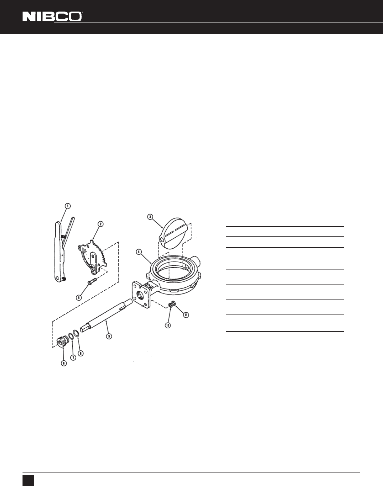
Refer to assembly drawing below for individual components.
www.nibco.com
MATERIAL LIST
ITEM DESCRIPTION
1. Lever Handle
2. Throttle Plate*
3. Disc
4. Wafer Body and Liner
5. Hex Bolt (3/8 x 2)
6. Collar Bushing
7. O-ring Body Seal
8. O-ring Stem Seal
9. Stem
10. Washer (3/8 x 2)
11. Nut (3/8-16 x 2)
* Shown with optional Infinite-Position Kit.
GEAR OPERATORS
All gear operators are lubricated for life at assembly, prior to shipment from factory.
During installation, customer should carefully adjust gear operators to suit the valve OPEN and SHUT positions; no further attention
is normally required throughout the product life.
For installations where spare parts are held on site, it is suggested that a spare gear operator be held as an interchangeable item.
In the event of gear operator suffering damage or excessive wear in service, it is recommended that a replacement be supplied.
** Never remove the collar bushing with the system under pressure.
10
NIBCO INC. WORLD HEADQUARTERS • 1516 MIDDLEBURY ST. • ELKHART, IN 46516-4740 • USA • PH: 1.800.234.0227
TECH SERVICES PH: 1.888.446.4226 • FAX: 1.888.234.0557 • INTERNATIONAL OFFICE PH: +1.574.295.3327 • FAX: +1.574.295.3455
www.nibco.com
 Loading...