

Page 1
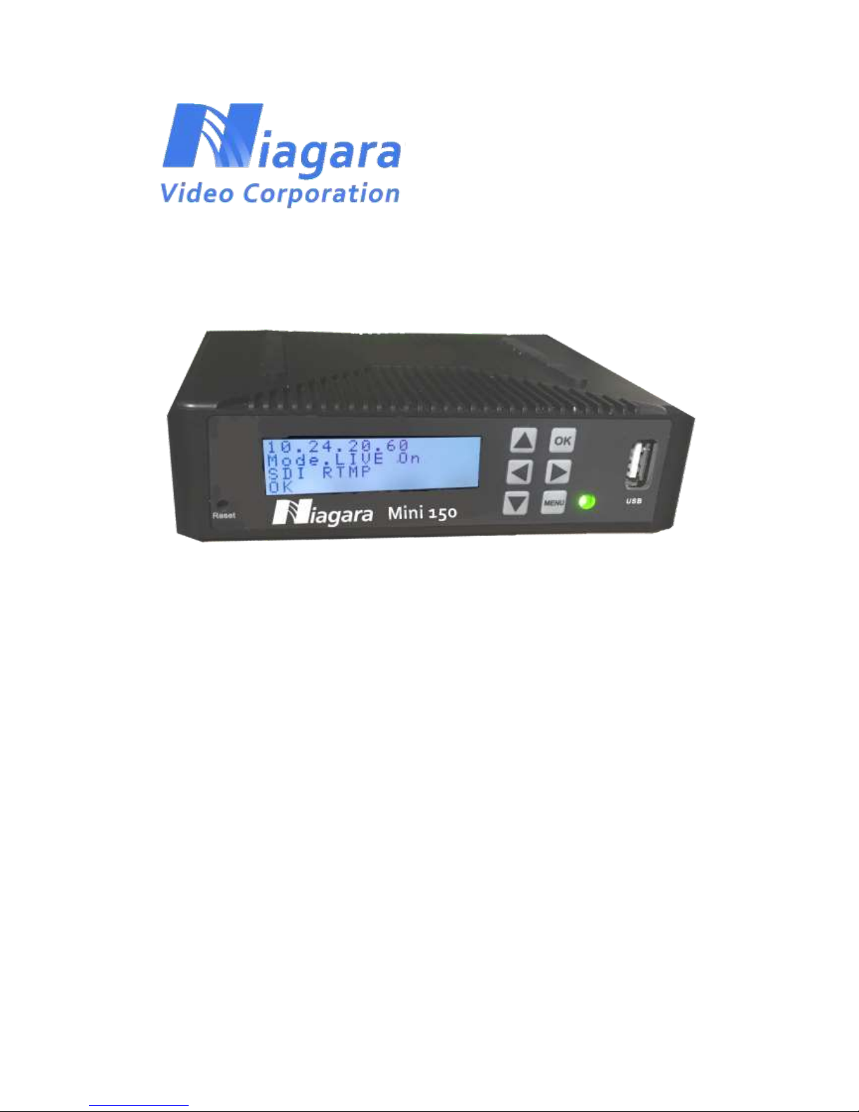
MINI 150 Encoder
User’s Manual
V1.0
Page 2

Page 1 NIAGARA VIDEO CORPORATION
Preface
About This Manual
This manual provides introductions to users about how to operate the device correctly. The content
includes an introduction to product installation, product characteristics and product settings, etc.
Intended Readers
This manual is suggested to be studied by the following readers:
Technical Service Engineer
Maintenance Engineer
Test Engineer
Sales Engineer
Page 3
Page 2 NIAGARA VIDEO CORPORATION
Important
Avoid personal injury and product damage! Do not proceed beyond any symbol until
you fully understand the indicated conditions. You may find this symbol in the
document that accompanies this product. This symbol indicates important operating
or maintenance instructions.
Please use good quality cables and make sure the connector is in good condition.
Please do not use a power supply that doesn’t match the input requirement.
Please do not open the encoder.
Specifications and functions may be changed for improvement without notice in
advance.
Page 4

Page 3 NIAGARA VIDEO CORPORATION
Notices
Trademark Acknowledgments
All trademarks shown in this manual are trademarks of their respective owners.
Publication Disclaimer
Our company assumes no responsibility for errors or omissions that may appear in this
publication. We reserve the right to change this publication at any time without notice. This
document is not to be construed as conferring by implication, estoppel, or otherwise any
license or right under any copyright or patent, whether or not the use of any information in
this document employs an invention claimed in any existing or later issued patent.
Copyright
Information in this publication is subject to change without notice. No part of this publication
may be reproduced or transmitted in any form, by photocopy, microfilm, xerography, or any
other means, or incorporated into any information retrieval system, electronic or
mechanical, for any purpose, without the express permission of our company.
Page 5

Page 4 NIAGARA VIDEO CORPORATION
Safety Instructions
This warning symbol means danger. You are in a situation that could cause bodily
injury. Before you work on any equipment, be aware of the hazards involved with
electrical circuitry and be familiar with standard practices for preventing accidents.
Electric Shock Hazard
This equipment meets applicable safety standards. Refer to this equipment's Identification
label or contact factory for details about regulatory compliance approvals.
WARNING:
To reduce risk of electric shock, perform only the instructions that are included in
the operating instructions. Refer all servicing and installation to qualified service
personnel only.
Electric shock can cause personal injury or even death. Avoid direct contact with
dangerous voltages at all times. The protective ground connection, where provided, is
essential to safe operation and must be verified before connecting the power supply.
Know the following safety warnings and guidelines:
- Only trained and qualified personnel should be allowed to install, replace, or service this
equipment.
- Only qualified service personnel are allowed to remove encoder covers and access any
of the components inside.
- There are no user-serviceable parts inside. Do not open.
Page 6

Page 5 NIAGARA VIDEO CORPORATION
Important Safety Instructions
Read these instructions.
Keep these instructions.
Heed all warnings.
Follow all instructions.
Do not use this apparatus near water.
Clean only with dry cloth.
Do not block any ventilation openings. Install in accordance with the manufacturer's
instructions.
Do not install near any heat sources such as radiators, heat registers, stoves, or
other apparatus (including amplifiers) that produce heat.
Protect the power cord from being walked on or pinched particularly at plugs,
convenience receptacles, and the point where they exit from the apparatus.
Only use attachments/accessories specified by the manufacturer.
Use only with the cart, stand, tripod, bracket, or table specified by the manufacturer,
or sold with the apparatus. When a cart is used, use caution when moving the
cart/apparatus combination to avoid injury from tip-over.
Unplug this apparatus during lightning storms or when unused for long periods of
time.
Refer all servicing to qualified service personnel. Servicing is required when the
apparatus has been damaged in any way, such as power-supply cord or plug is
damaged, liquid has been spilled or objects have fallen into the apparatus, the
apparatus has been exposed to rain or moisture, does not operate normally, or has
been dropped.
Page 7

Page 6 NIAGARA VIDEO CORPORATION
WARNING:
To reduce the risk of fire or electric shock, do not expose this apparatus to rain or
moisture. The apparatus shall not be exposed to dripping or splashing and no
objects filled with liquids, such as vases, shall be placed on the apparatus.
Page 8

Page 7 NIAGARA VIDEO CORPORATION
Contents
1 OVERVIEW ...................................................................................................................................... 8
1.1 Introduction.................................................................................................................. 8
1.2 Architecture .................................................................................................................. 8
Front Panel ................................................................................................................................ 8
Rear Panel ................................................................................................................................. 8
2 INSTALLATION ................................................................................................................................. 9
2.1 Installation Procedure ......................................................................................................... 9
2.2 Preparation before Installation ........................................................................................... 9
2.3 Check Package and Contents............................................................................................. 10
2.4 Equipment Wiring and Connection ................................................................................... 10
2.4.1 Power Connection .......................................................................................................... 10
2.4.2 DC Power Connection .................................................................................................... 10
2.4. 3 Connection Setup for Web Management ..................................................................... 11
2.4.4 Connection Setup for HDMI/CVBS/SDI signal input ....................................................... 11
3 OPERATION GUIDE ....................................................................................................................... 11
3.1 Operating the Front Panel Interface.................................................................................. 11
3.1.1 Powering Up and Initialization ............................................................................... 11
3.1.2Front Panel Menu Structure .................................................................................... 12
3.2 Operating the WEB Interface ............................................................................................ 13
3.2.1 Access Interface...................................................................................................... 13
3.2.2 Main Interface ........................................................................................................ 14
3.2.3 Live Mode ............................................................................................................... 15
3.2.4 Playback mode ....................................................................................................... 21
3.3.5 Recording Mode ..................................................................................................... 23
3.3.6 System .................................................................................................................... 24
Page 9
Page 8 NIAGARA VIDEO CORPORATION
1 OVERVIEW
1.1 Introduction
The Niagara Mini 150 is a highly effective encoder for video and audio processing which supports
HDMI/SDI/CVBS standard input sources and outputs as RTSP/HLS/UDP/RTP/RTMP Ethernet
protocols. The Mini 150 supports one channel HD/SD live encoding and one IP stream out.
1.2 Architecture
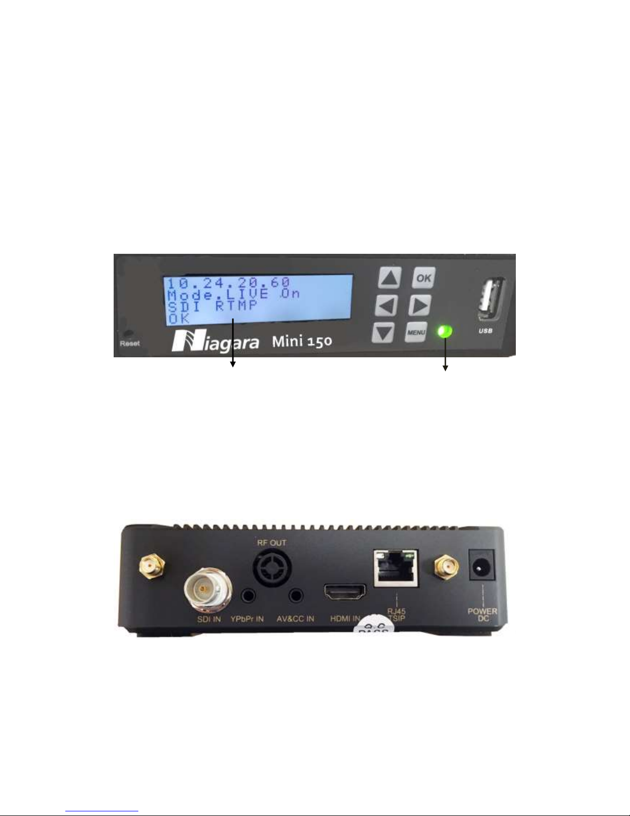
Front Panel
2 1
1. Power status indicator: This LED light is turned on when the encoder is powered on.
Signal Lock status indicator: This LED light turns to green when a channel is locked.
Otherwise the light turns to red.
2. Display screen: This LCD screen can show the management IP address, work mode, Input
stream standard, output protocol, running status and etc.
Rear Panel
1. HDMI /AV /YPbPr/SDI IN port
2. RJ45-- management connection port
3. Power DC—DC Power connection
4. WiFi Antenna connectors
Page 10
Page 9 NIAGARA VIDEO CORPORATION
2 INSTALLATION
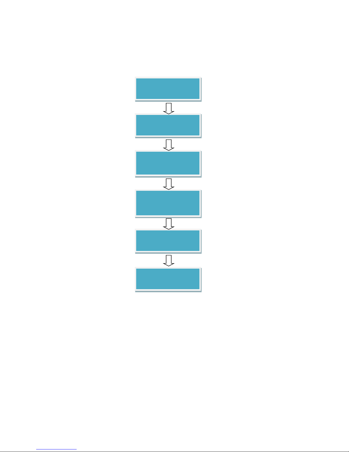
2.1 Installation Procedure
2.2 Preparation before Installation
Before installation, you should read through and confirm the following:
Go through this user manual.
Have knowledge of digital television system.
Defined the sources, racks allocation, and set-up plan system wiring.
Knows how to configure and operate this encoder.
Go through related engineering design documents about the system.
Preparation before
Installation
Check Package and
Accessories
Setup Connection
(signals, wiring)
Parameters
Configuration
System Debug
Finish
Page 11

Page 10 NIAGARA VIDEO
CORPORATION
2.3 Check Package and Contents
The MINI 150 package includes the following:
Base Unit x1
Power Supply x1
HDMI cable x1
WiFi Antenna x2
RCA AV cable x1
Flash Drive with User Guide x1
2.4 Equipment Wiring and Connection
To avoid electric shock and damage to the equipment, before setting up the wiring connection,
please power off the equipment and all other connected external devices. Powering on the
equipment only after all the wiring connection is completed.
2.4.1 Power Connection
Use the proper power connections is vital to the safe operation of the portable encoder. Only use
the supplied 3-prong power connector or one with equal specifications. Never tamper or remove
the 3rd-Prong grounding pin. This could cause damage to the Portable Encoder.
2.4.2 DC Power Connection
The MINI 150 encoder is intended to be use on either 120V or 240V systems. The power supply
will automatically detect the system which is connected to. To hook up the power use the
following steps:
1. Locate the DC power cord which is included with the MINI 150.
2. Plug the female end of the power cord (end with no prongs) into the back of the unit.
3. Locate a protected outlet (usually inside of the rack) to plug the male end of the power cable
into.
Page 12
Page 11 NIAGARA VIDEO
CORPORATION
2.4. 3 Connection Setup for Web Management
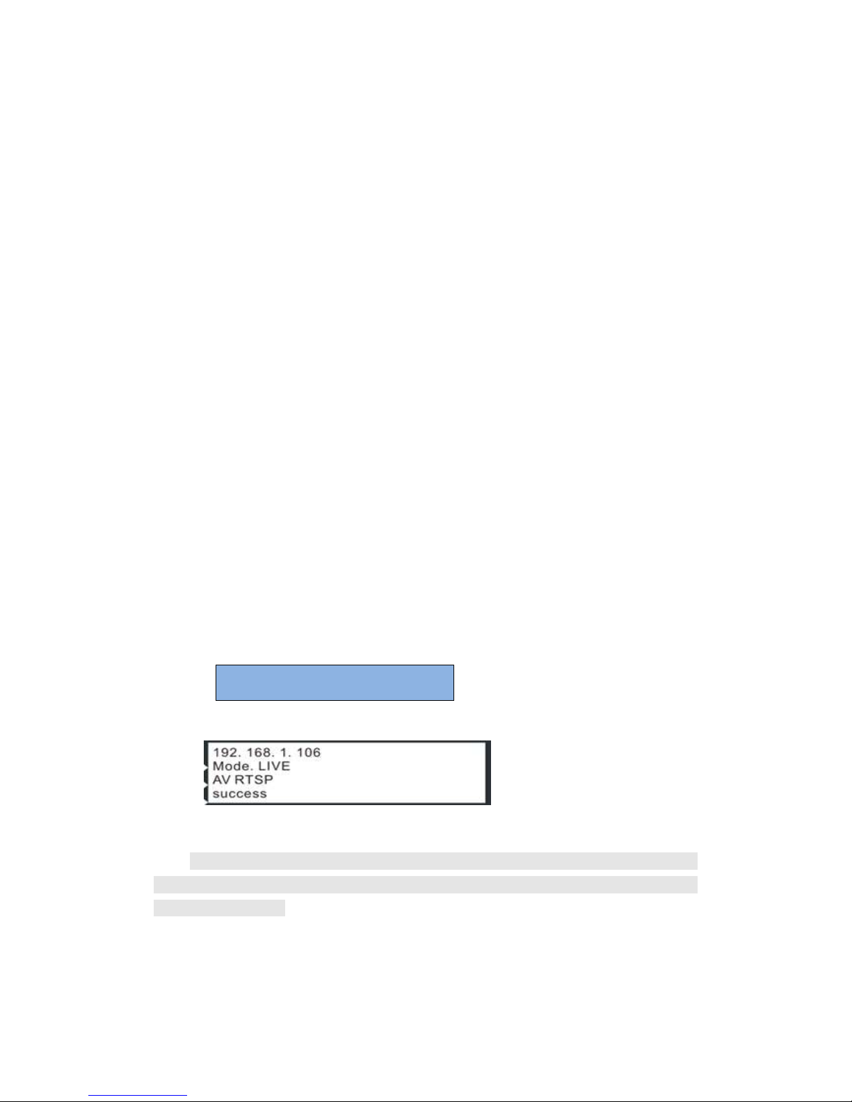
Connect the MINI 150 Management port with a network cable and set up a management
network with the management PC. The default IP address is 192.168.1.106
2.4.4 Connection Setup for HDMI/CVBS/SDI signal input
Connect HDMI/CVBS/SDI signal to MINI 150 “HDMI IN”/”AV IN”/ “YPbPr IN”/”SDI IN” port with a
HDMI /AV/YPbPr/SDI cable.
3 OPERATION GUIDE
3.1 Operating the Front Panel Interface
3.1.1 Powering Up and Initialization
Before powering-up the device, make sure that all cabling is correctly connected (refer to
chapter 2.4 of this manual) and the device is correctly connected to the power supply.
Connect the Power port and the unit is powered up and starts the initialization.
The LCD screen lights up and displays the following:
The initialization takes about 20 seconds to complete, and then the LCD screen display as following:
Note: If the unit fails to initialize and hangs at the “booting” stage, switching off the device and
then powering up again may help. If the device still fails to initialize, please contact your service
representative for help.
Booting…
Page 13

Page 12 NIAGARA VIDEO
CORPORATION
3.1.2Front Panel Menu Structure
1st Layer
2nd Layer
3rd Layer
4th Layer
Status
live
Playing
Paused
Playback
Playing
Paused
Record
Playing
Paused
Setting
Work
Mode
live
Input
Auto
HDMI/YPbPr
SDI/AV
Output
UDP/RTP/RTSP/
HLS Live/RTMP
IP
x.x.x.x
OK
Port
1234
OK
Back
Playback
Mode
Sequence
Play Single
List
Random
IP
x.x.x.x
OK
Port
1234
OK
Back
Recorded
Recording Input
Auto
HDMI/YPbPc
SDI/AV
Back
System
Network
Mode
DHCP
Enable/Disable
DNS
Static/ Dynamic
OK
Back
Host IP/Gateway/
Mask/DNS
x.x.x.x
OK
Back
AP
Wi-Fi ON/OFF
Back
Page 14

Page 13 NIAGARA VIDEO
CORPORATION
Version
SW/FW/HW
version
Back
Recovery
Yes/NO
Back
Reboot
Yes/NO
Back
Back
Back
Back
Press ”OK” to apply, press arrow up and down to move to other items.
3.2 Operating the WEB Interface
3.2.1 Access Interface
PC Web-GUI
The Mini 150 can be accessed and configured via web GUI. The accessing instruction is as the
followings:
1. Connect the “RJ45” port of the Mini 150 to a network switch and connect the management
PC/server to the same network switch.
2. The Mini 150 default IP address is 192.168.1.106. Please modify the management
server’s IP address or Mini 150 IP address to be in the same IP section. To ensure that the
equipment is smoothly connected to the network.
3. Open any web browser (e.g. Mozilla v30 or above, IE8.0 or above, safari, chrome v42 or
above and etc.), input the equipment’s IP address in format: http://xxx.xxx.xxx.xxx
(xxx.xxx.xxx.xxx refers to Mini 150’s IP address) and press ENTER button to confirm. The
browser will attempt to connect to the device. If successful, a login page will appear. (see
PIC-3.2.1)
Page 15

Page 14 NIAGARA VIDEO
CORPORATION
Pic-3.2.1
The default login info shows as below. Click “Sign in” button after input the correct user name
and password.
User Name: admin
Password: admin.
Wireless connection to device:
Please refer to 3.3.6 System Wi-Fi Hotspot.
3.2.2 Main Interface
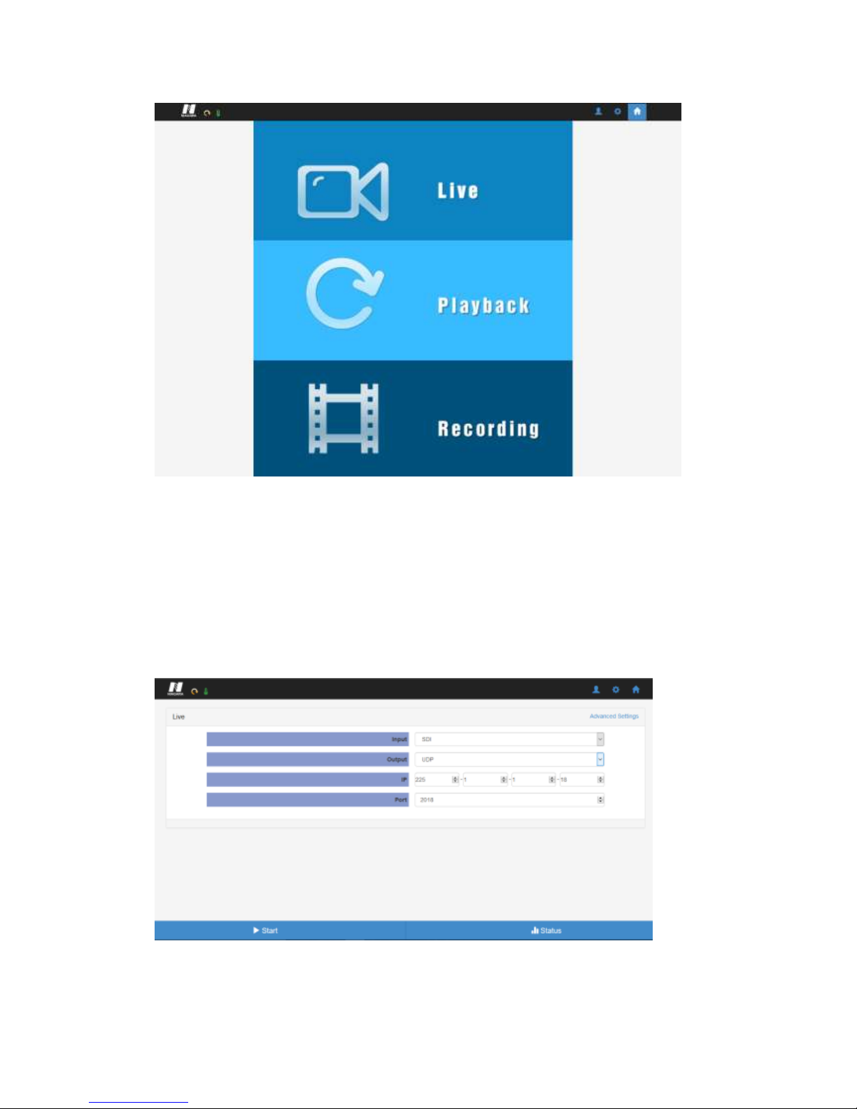
There are 3 working modes: Live, Playback and Recording. Click to enter desire working mode. (PIC-
3.2.2)
Live Mode: to encode a live channel via HDMI/SDI/CVBS input and IP output.
Playback Mode: to play the recorded TS from the external USB disk.
Recording Mode: to record the encoded TS and store it to the external USB disk
Page 16
Page 15 NIAGARA VIDEO
CORPORATION
Pic-3.2.2
3.2.3 Live Mode
To set the parameters for HD/SD channels encoding, as well as the broadcasting mode and
parameters.
Basic Setting
Pic-3.2.2.1
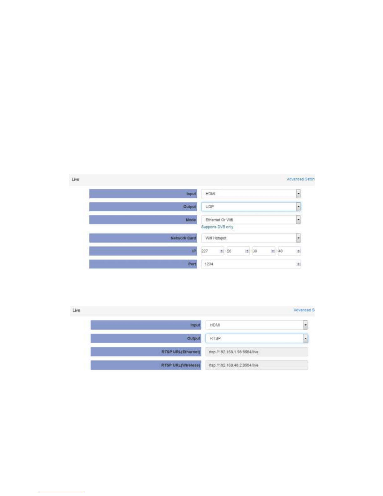
This interface provides the main parameters of encoding and broadcasting. Please check and set
Page 17
Page 16 NIAGARA VIDEO
CORPORATION
the parameter according to the following items:
Input: Auto/HDMI/SDI/ YPbPr /AV source can be selected
Output: support UDP/RTSP/HLS/RTP/RTMP/QAM protocol
Mode: Ethernet / Ethernet or Wi-Fi can be selected
Network Card: support Ethernet
IP/Port: you can configure the IP streaming output address
UDP Settings
Pic-3.2.2.1-1
RTSP Settings
Pic-3.2.2.1-2
Page 18

Page 17 NIAGARA VIDEO
CORPORATION
HLS Settings
Pic-3.2.2.1-3
RTP Settings
Pic-3.2.2.1-4
RTMP Settings
Pic-3.2.2.1-5
Advanced Setting
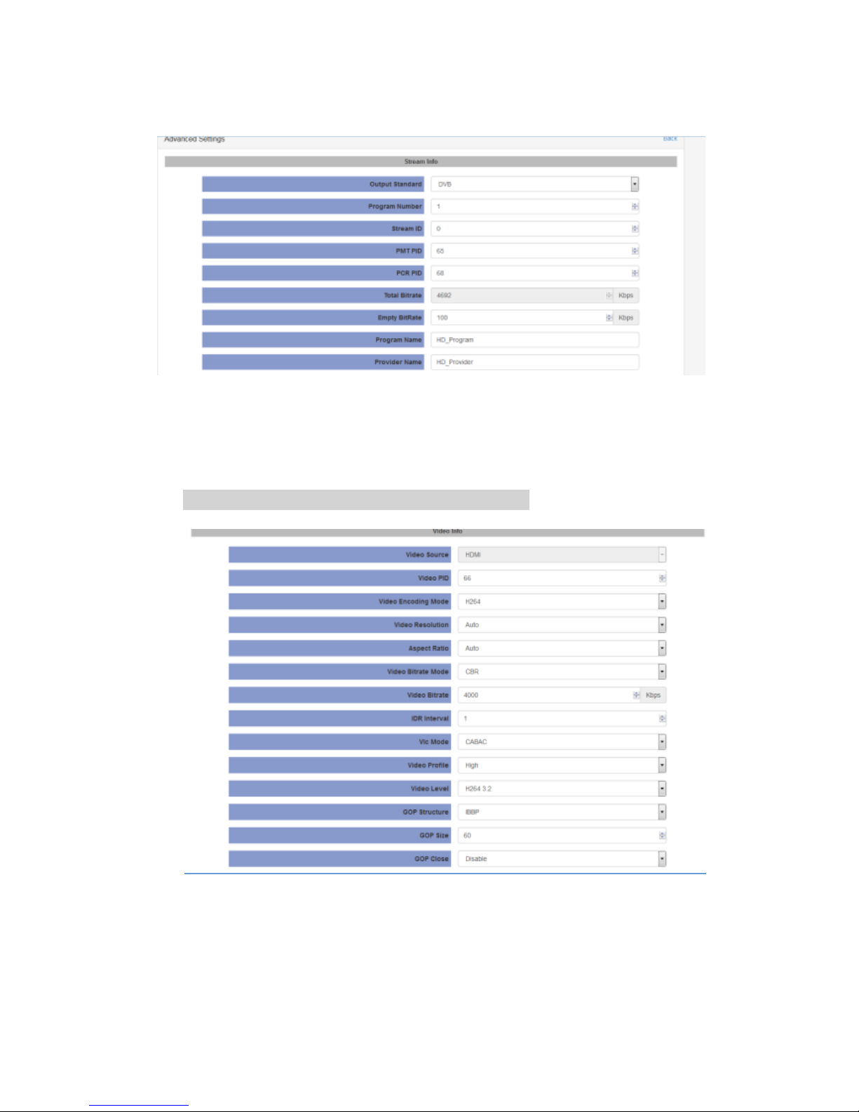
To configure the advanced setting for encoding and streaming, please click the “Advanced” link in
blue. It will take you to a new page to set the detailed parameters for Live Mode. It contains three
parts of configuration: Stream info, Video info and Audio info (Dolby D St Creator)
Page 19
Page 18 NIAGARA VIDEO
CORPORATION
Pic-3.2.2.2
Stream info: In this page, you can configure the Output Standard, Program Number, Stream
ID, PMT PID, PCR PID and etc.(Pic-3.2.2.2)
Note: For Empty BitRate, there may be a PCR error if set to 0!
Pic-3.2.2.3
Video Info (refer to Pic-3.2.2.3)
Video Source: base on the source you selected in basic setting page
Page 20

Page 19 NIAGARA VIDEO
CORPORATION
Video PID: ranging from 32-8190
Video Encoding Mode: DVB/MPEG
Video Resolution: Auto/User can choose certain output resolution
Resolutions Supported:
HD: 1920 x 1080@24p/25p/30p/50i/60i,1280 x720@50p/60p/25p/30p
SD: 720 x 576@50i, 720 x 480@60i
Aspect Ratio: Auto, 16x9_Letter Box, 16x9_Cutoff, 4x3_Pillar Box and 4x3_Cutoff
Video Bitrate Mode: CBR /VBR
Video Bitrate: ranging from 800 to 14000Kpbs(MPEG2/H.264)
IDR Interval: the range is 0-20
Vlc Mode: CABAC/CAVLC
Video Profile: High/Main
Video Level: H.264 3.0/ H.264 3.1/ H.264 3.2/ H.264 4.0/ H.264 4.1/ H.264 4.2
GOP Structure: IBBP, IPPP,IBP,IBBBP
GOP Close: Enable/Disable
Note: When input signal is detected and the preset output signal is of the allowed ones (see
mapping table below), the preset will be remained, otherwise the output resolution will changed
to Auto automatically.
input signal
preset output signal
1920x1080_30p
1920x1080_30p
1280x720_30p
720x480_60i
1920x1080_60i
1920x1080_30p
1920x1080_60i
1280x720_30p
720x480_60i
Page 21
Page 20 NIAGARA VIDEO
CORPORATION
1920x1080_24p
1920x1080_24p
1920x1080_50i:/
1920x1080_25p
1920x1080_50i
1280x720_25p
720x576_50i
1280x720_60p:
1280x720_60p
1280x720_30p
720x480_60i
1280x720_50p
1280x720_50p
1280x720_25p
720x576_50i
720x480_60i:
720x480_60i
720x576_50i
720x576_50i
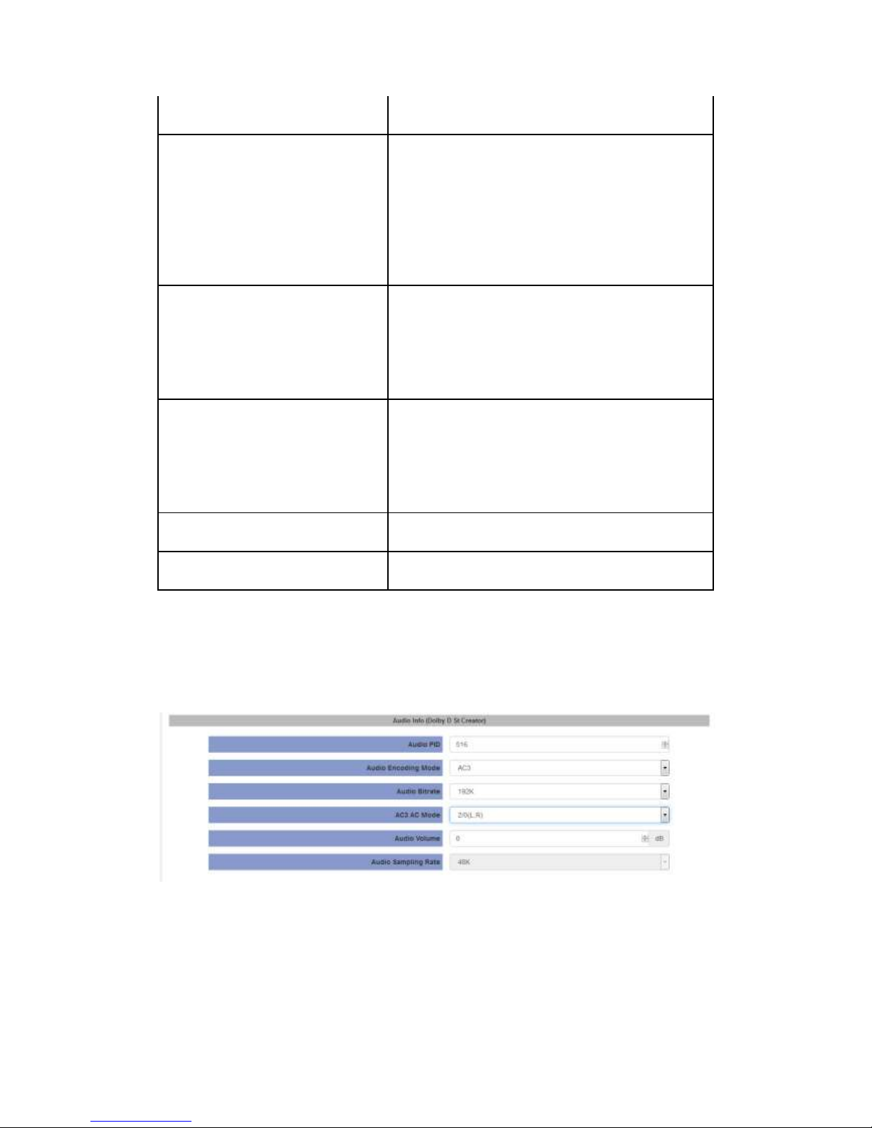
Audio Info(Dolby D St Creator)
Pic-3.2.2.4
Audio Source: HDMI Audio source could be selected
Audio PID: ranging from 32-8190
Page 22
Page 21 NIAGARA VIDEO
CORPORATION
Audio Encoding Mode: AC3/MPEG1 Layer2/MPEG2 AAC-LC/MPEG4 AAC-LC
Audio Bitrate: 128K/192K/256K/384K
AC3 AC mode: 1+1(L,R), 1/0(C), 2/0(L,R)
Audio Volume: -12 - 12
Audio Sampling Rate: 48K is fixed output audio sampling rate
Click Apply button to make the new configuration into effect when finishing the setting.
Click Start button to make the encoding into effect;
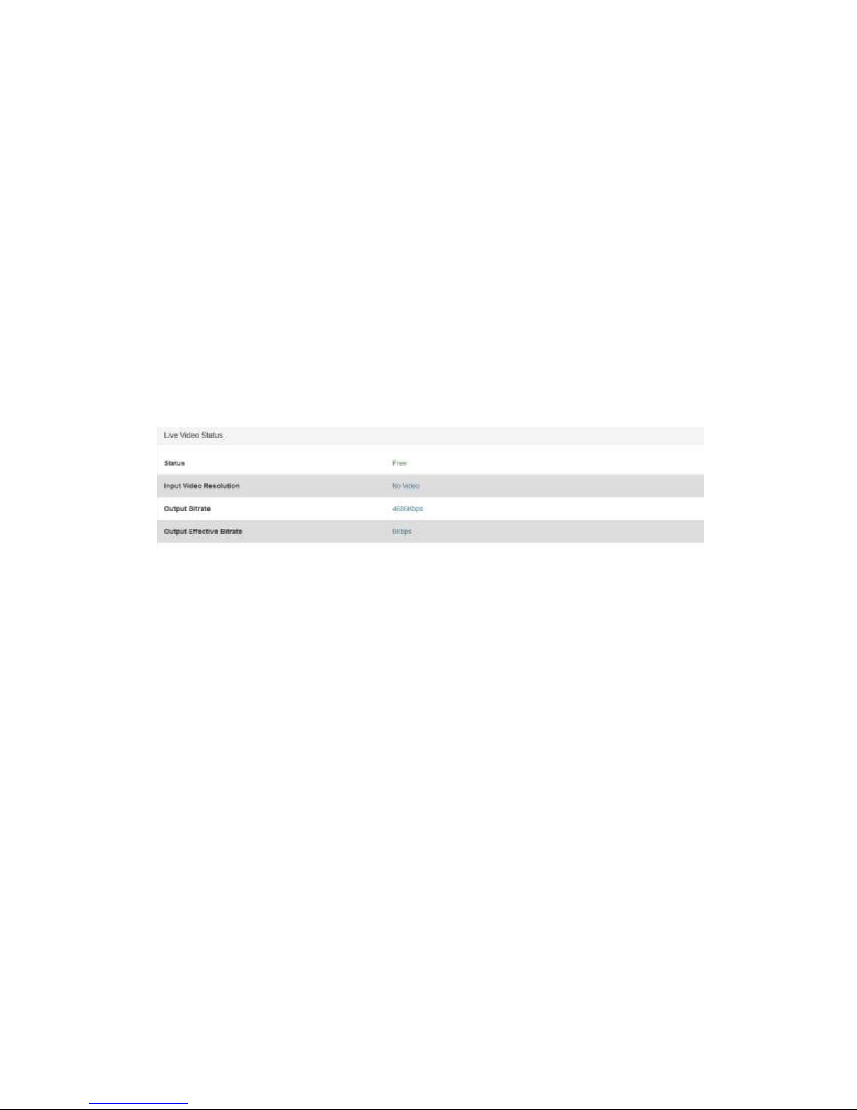
Live Status
Click the Status icon on the right-bottom to get reflect to the live status page. The page displays
and updates the real-time status of encoding and streaming.
3.2.4 Playback mode
Basic Setting
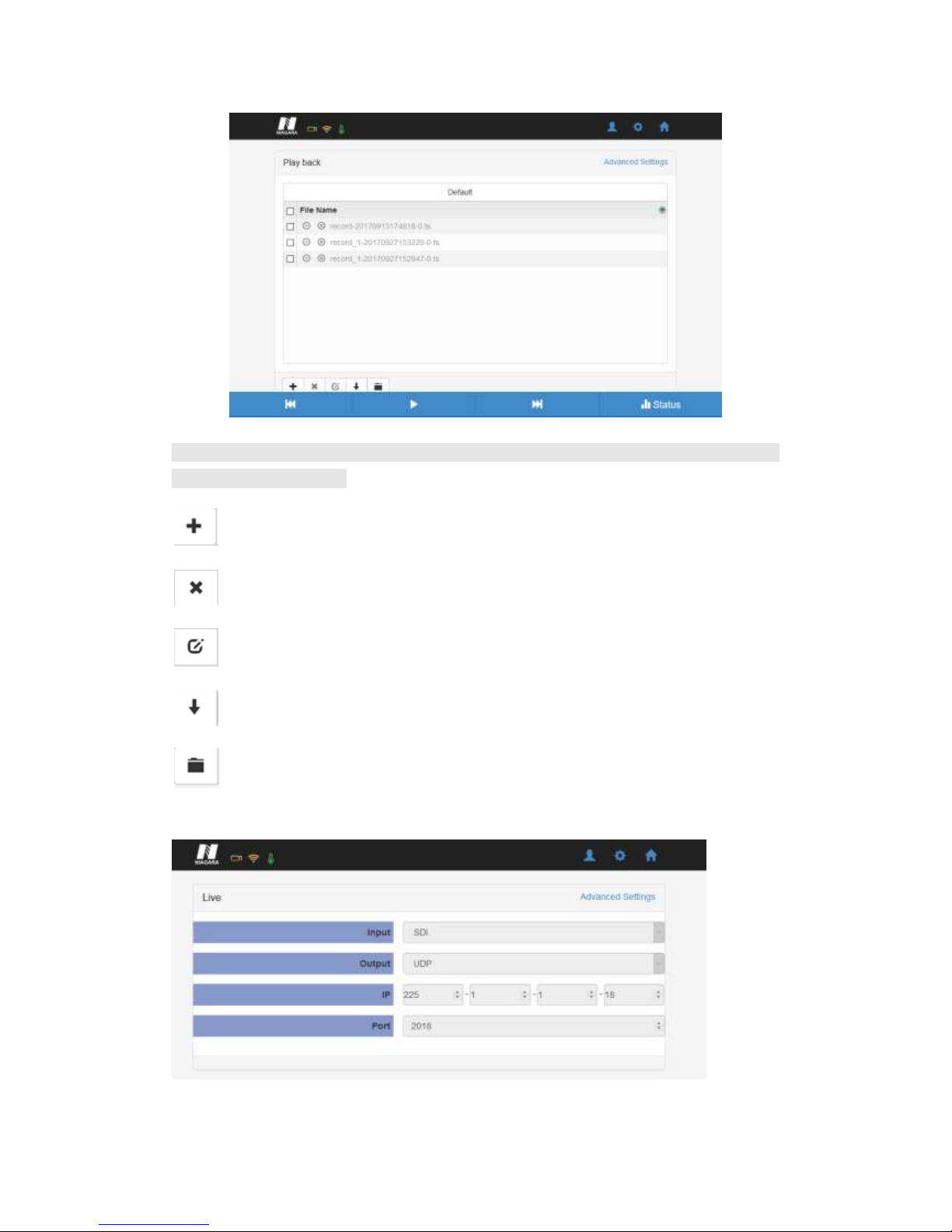
1. Plug one USB disk to USB port on the front panel of the MINI 150 to play the TS from the disk.
2. Click the PLAYBACK icon to get the playback page, which will list all the available TS from the
USB disk.
3. Click the required TS to play the TS.
Page 23
Page 22 NIAGARA VIDEO
CORPORATION
Note: The Playback interface will save and display the TS list from memory of the last USB disk if
there is no disk connected.
: to add new Play list. The default play list is named “default”.
: to delete the existing Play list.
: to modify the play list name.
: to change the play mode, including single cycle, listing loop, random, order playback.
: to add new TS to the play list.
Live Settings
IP: The destination IP address for IP streaming.
Page 24
Page 23 NIAGARA VIDEO
CORPORATION
Port: The destination IP port for IP streaming.
Mode: Ethernet/Wi-Fi could be selected.
Network Card: Ethernet.
Daily play plan: To set the play plan.
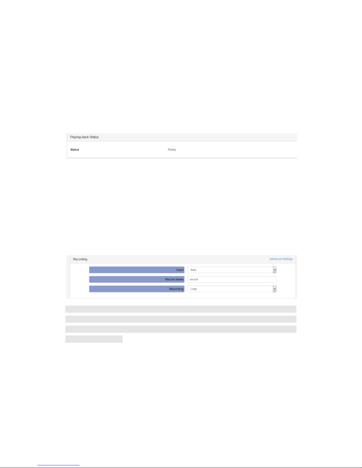
Playback Status
This page displays the status of Playback.
3.3.5 Recording Mode
Basic Setting
1. Connect the USB disk to the Mini 150.
2. Set the encoding parameter, and click the start icon to start the recording or pause to stop the
recording.
3. Click the status icon to reflect to the Status page.
Note: If the USB disk is not connected or there is not enough space on the disk, it is not able to
start the recording. The minimum available free space is 10MB. The Mini 150 will overwrite the
first file it created when the free space is not enough, all those files which are not created by Mini
150 will not be affected.
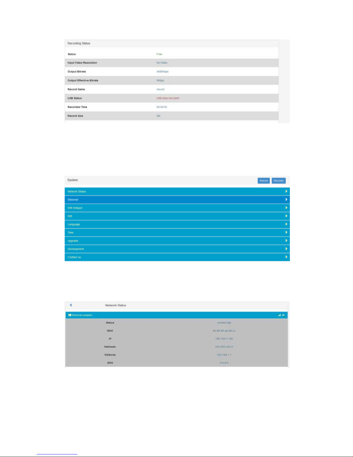
Recording Status
This page offers the status of the recording and the storage of the connected USB disk.
Page 25
Page 24 NIAGARA VIDEO
CORPORATION
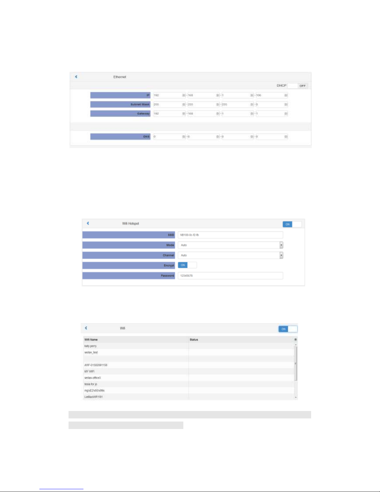
3.3.6 System
The System page provides the Network parameters, Language setup, time setup, upgrade, log and
system info. (Pic-3.3.6.1)
Pic-3.3.6.1
Network Status: This page shows status of network related info:
Pic-3.3.6.2
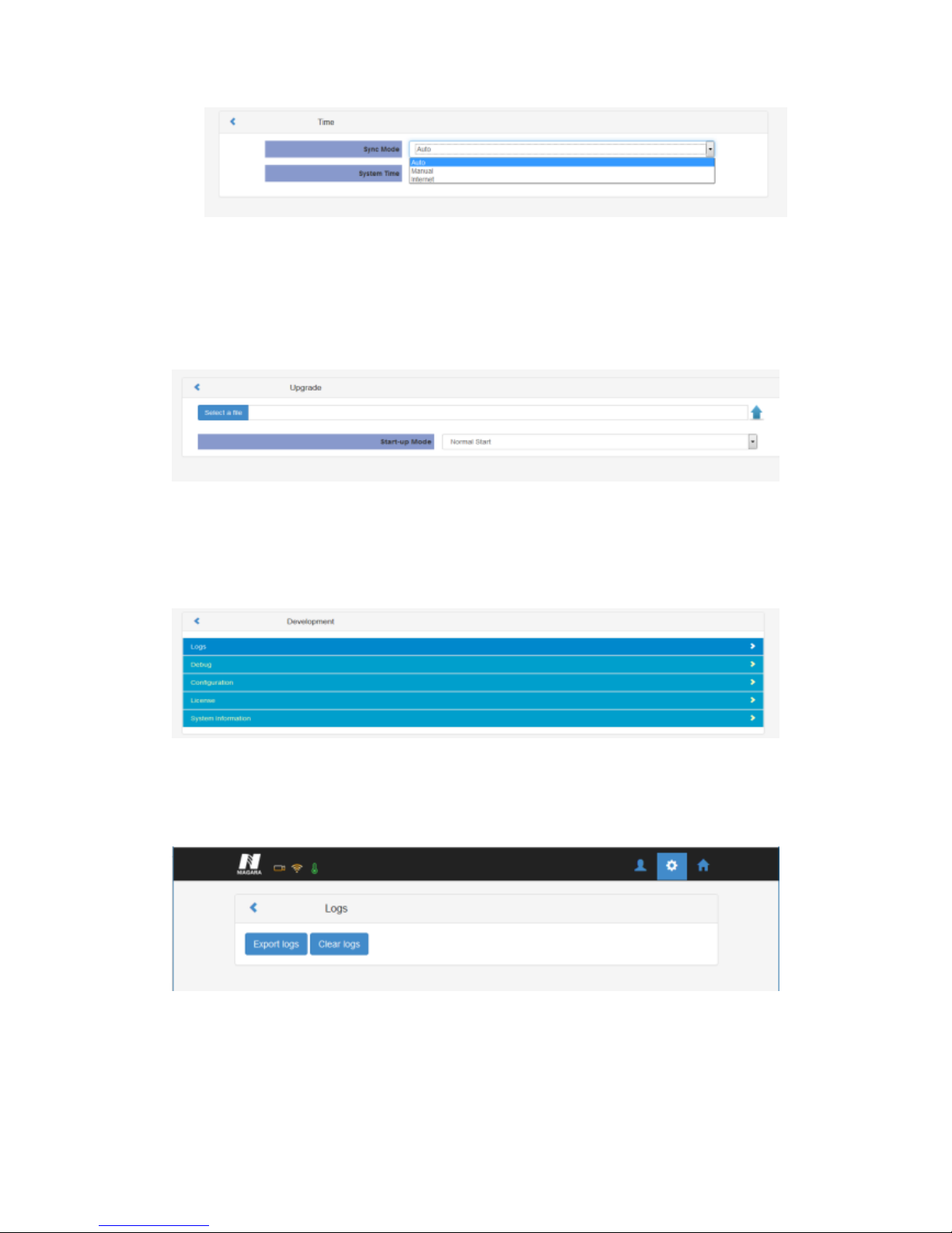
Ethernet: to set up equipment management access IP address, Subnet Mask, Gateway and
Page 26
Page 25 NIAGARA VIDEO
CORPORATION
etc.(see Pic-3.3.3.3) The MINI 150 can be configured to use DHCP to obtain an IP
address/Subnet Mask/Gateway. To obtain an IP address may require up to one minute.
Pic-3.3.6.3
Wi-Fi Hotspot:
This page shows how to set up a Wi-Fi Hotspot which enables a PC, phone or Tablet to log in
via wireless connection to the device.
Wi-Fi
The Mini 150 can connect to a WiFi Network.
Note: Wi-Fi hotspot and Wi-Fi reception have the same range. When it is used as a hotspot, Wi-Fi
reception is disabled automatically, vice versa.
Time: to configure the system time with Manual or Internet time.
Page 27
Page 26 NIAGARA VIDEO
CORPORATION
Pic-3.3.6.5
Upgrade: to upgrade new version software by selecting a file and clicking the Arrow button.
It will take several minutes to finish the upgrading and after that, it will need to be
rebooted.(Refer to Pic-3.3.3.6)
Pic-3.3.6.6
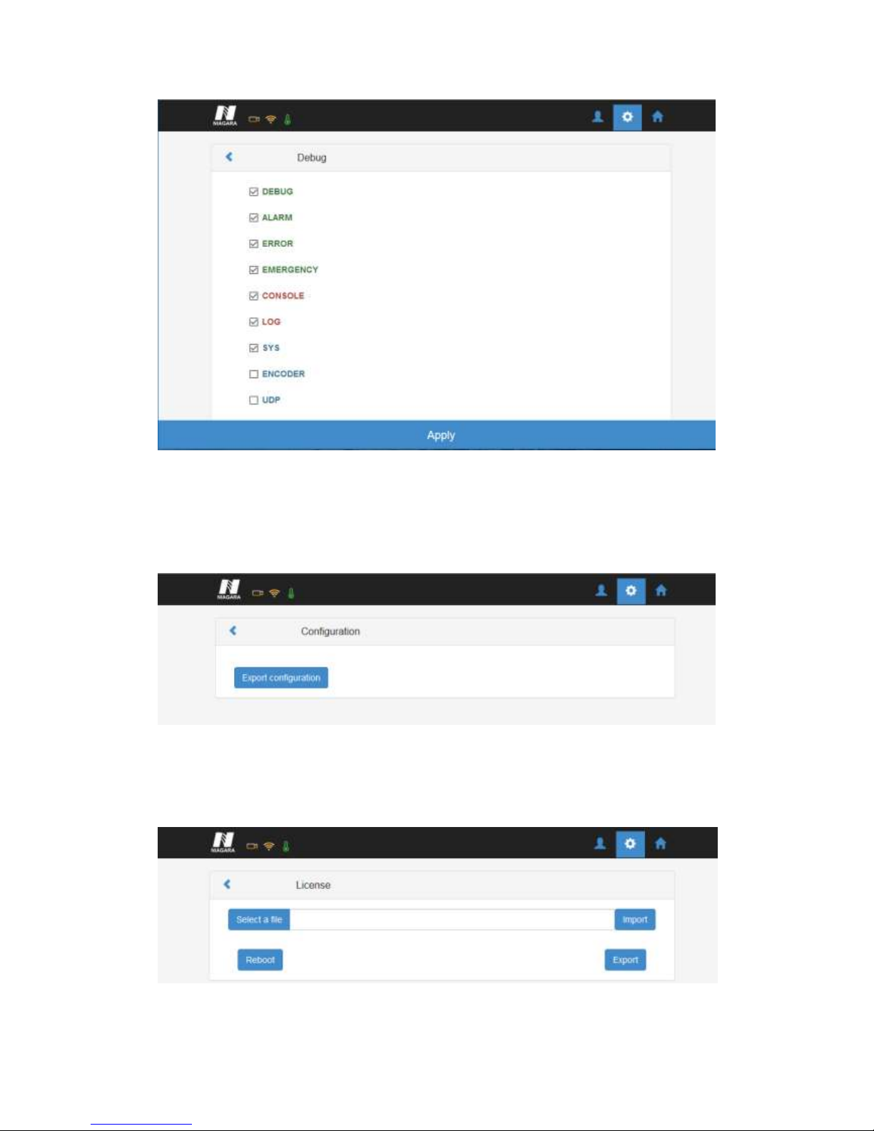
Development: to export and clear the logs, check the debug info, export configuration,
export& upgrade license and view system information.
Pic-3.3.6.7
Logs: User can export and clear the logs in this interface.
Pic-3.3.6.7-1
Debug: User can check the debug info which is usually used for R-D.
Page 28
Page 27 NIAGARA VIDEO
CORPORATION
Pic-3.3.6.7-2
Configuration: User can export configuration (including system and service configuration) in this
tab.
Pic-3.3.6.7-3
License: User can export and upgrade the license, a reboot is needed to active the license.
Pic-3.3.6.7-4
Page 29
Page 28 NIAGARA VIDEO
CORPORATION
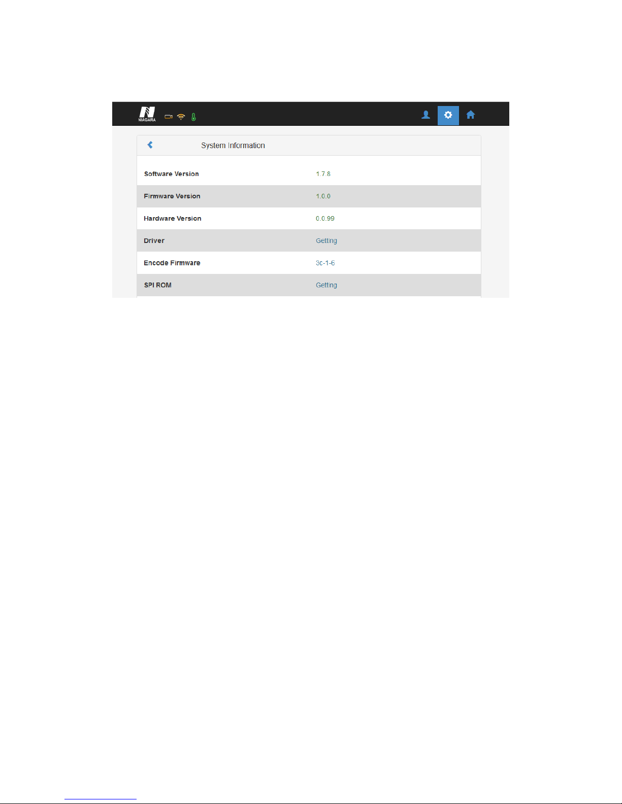
System information: User can check the system info in this tab.
Pic-3.3.6.7-5
 Loading...