


Artisan Technology Group is your source for quality
new and certied-used/pre-owned equipment
• FAST SHIPPING AND
DELIVERY
• TENS OF THOUSANDS OF
IN-STOCK ITEMS
• EQUIPMENT DEMOS
• HUNDREDS OF
MANUFACTURERS
SUPPORTED
• LEASING/MONTHLY
RENTALS
• ITAR CERTIFIED
SECURE ASSET SOLUTIONS
SERVICE CENTER REPAIRS
Experienced engineers and technicians on staff
at our full-service, in-house repair center
Instra
Remotely inspect equipment before purchasing with
our interactive website at www.instraview.com
Contact us: (888) 88-SOURCE | sales@artisantg.com | www.artisantg.com
SM
REMOTE INSPECTION
View
WE BUY USED EQUIPMENT
Sell your excess, underutilized, and idle used equipment
We also offer credit for buy-backs and trade-ins
www.artisantg.com/WeBuyEquipment
LOOKING FOR MORE INFORMATION?
Visit us on the web at www.artisantg.com for more
information on price quotations, drivers, technical
specications, manuals, and documentation

FieldPoint™ Operating Instructions
FP-AIO-600 and cFP-AIO-600
Four-Channel Analog Input,
Four-Channel Analog Output, 12-Bit Module
These operating instructions describe how to install and use the
National Instruments FP-AIO-600 and cFP-AIO-600 (referred to
inclusively as the [c]FP-AIO-600). For information about
configuring and accessing the [c]FP-AIO-600 over a network, refer
to the user manual for the FieldPoint network module you are
using.
Features
The [c]FP-AIO-600 is a FieldPoint analog input and output module
with the following features:
• Four analog voltage or current input channels with 11 input
ranges up to 36 V or 24 mA with overranging
• Four analog current output channels with 0–20 or 4–20 mA
ranges without overranging
• 1.7 kHz hardware update rate
• 12-bit resolution
• –40 to 70 °C operation
• Onboard diagnostics including open current loop indicators
• Current inputs protected up to 100 mA or 10 V
•250V
verified by 2,300 V
• Hot swappable
CAT II continuous channel-to-ground isolation,
rms
, 5 s dielectric withstand test
rms
Artisan Technology Group - Quality Instrumentation ... Guaranteed | (888) 88-SOURCE | www.artisantg.com

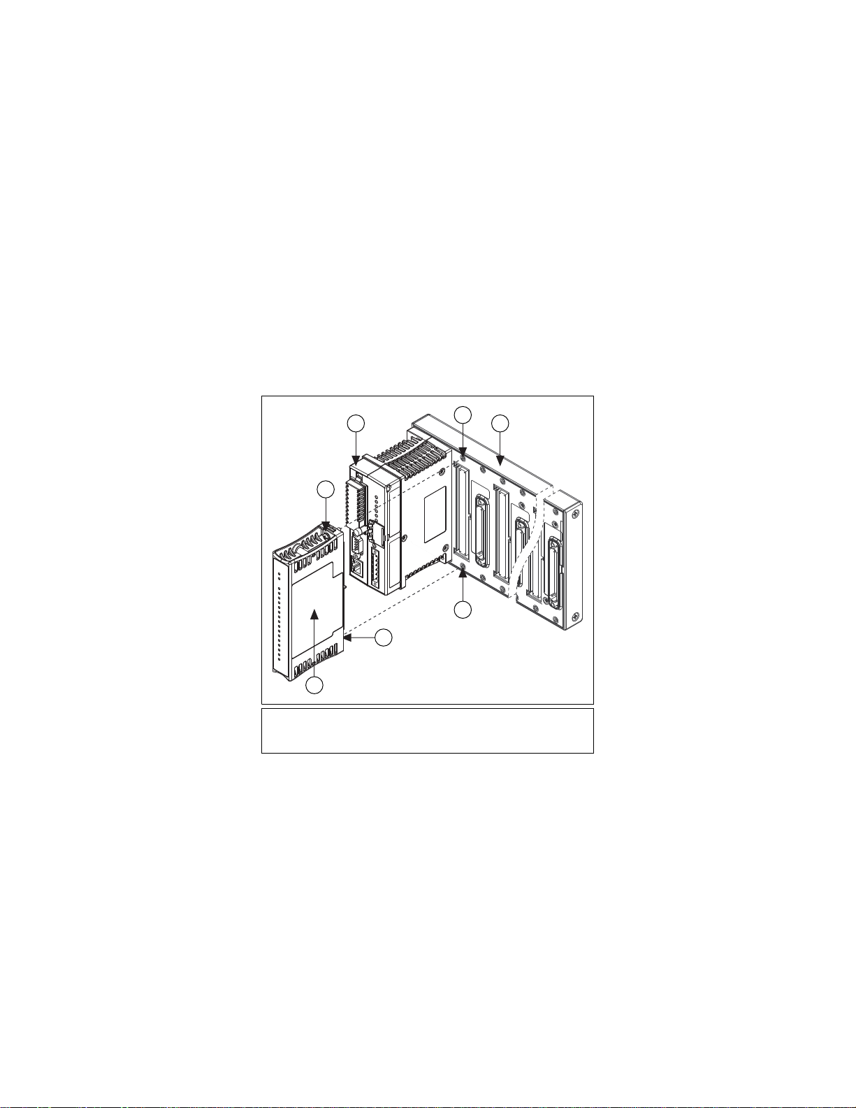
Installing the FP-AIO-600
1
3
2
4
5
6
The FP-AIO-600 mounts on a FieldPoint terminal base (FP-TB-x),
which provides operating power to the module. Installing the
FP-AIO-600 onto a powered terminal base does not disrupt the
operation of the bank.
To install the FP-AIO-600, refer to Figure 1 and complete the
following steps:
1. Slide the terminal base key to position X.
2. Align the FP-AIO-600 alignment slots with the guide rails on
the terminal base.
3. Press firmly to seat the FP-AIO-600 on the terminal base.
When the module is firmly seated, the terminal base latch locks
it into place.
1 I/O Module
2Terminal Base
3 Alignment Slot
Figure 1. Installing the FP-AIO-600
4Key
5Latch
6 Guide Rails
Installing the cFP-AIO-600
The cFP-AIO-600 mounts on a Compact FieldPoint backplane
(cFP-BP-x), which provides operating power to the module.
Installing the cFP-AIO-600 onto a powered backplane does not
disrupt the operation of the bank.
FP-AIO-600 and cFP-AIO-600 2 ni.com
Artisan Technology Group - Quality Instrumentation ... Guaranteed | (888) 88-SOURCE | www.artisantg.com
To install the cFP-AIO-600, refer to Figure 2 and complete the
2
2
1
3 5
4
4
following steps:
1. Align the captive screws on the cFP-AIO-600 with the holes on
the backplane. The alignment keys on the cFP-AIO-600
prevent backward insertion.
2. Press firmly to seat the cFP-AIO-600 on the backplane.
3. Using a number 2 Phillips screwdriver with a shank of at least
64 mm (2.5 in.) length, tighten the captive screws to 1.1 N m
(10 lb in.) of torque. The nylon coating on the screws prevents
them from loosening.
1 cFP I/O Module
2 Captive Screws
3 cFP Controller Module
Figure 2. Installing the cFP-AIO-600
© National Instruments Corp. 3 FP-AIO-600 and cFP-AIO-600
Artisan Technology Group - Quality Instrumentation ... Guaranteed | (888) 88-SOURCE | www.artisantg.com
4 Screw Holes
5 cFP Backplane
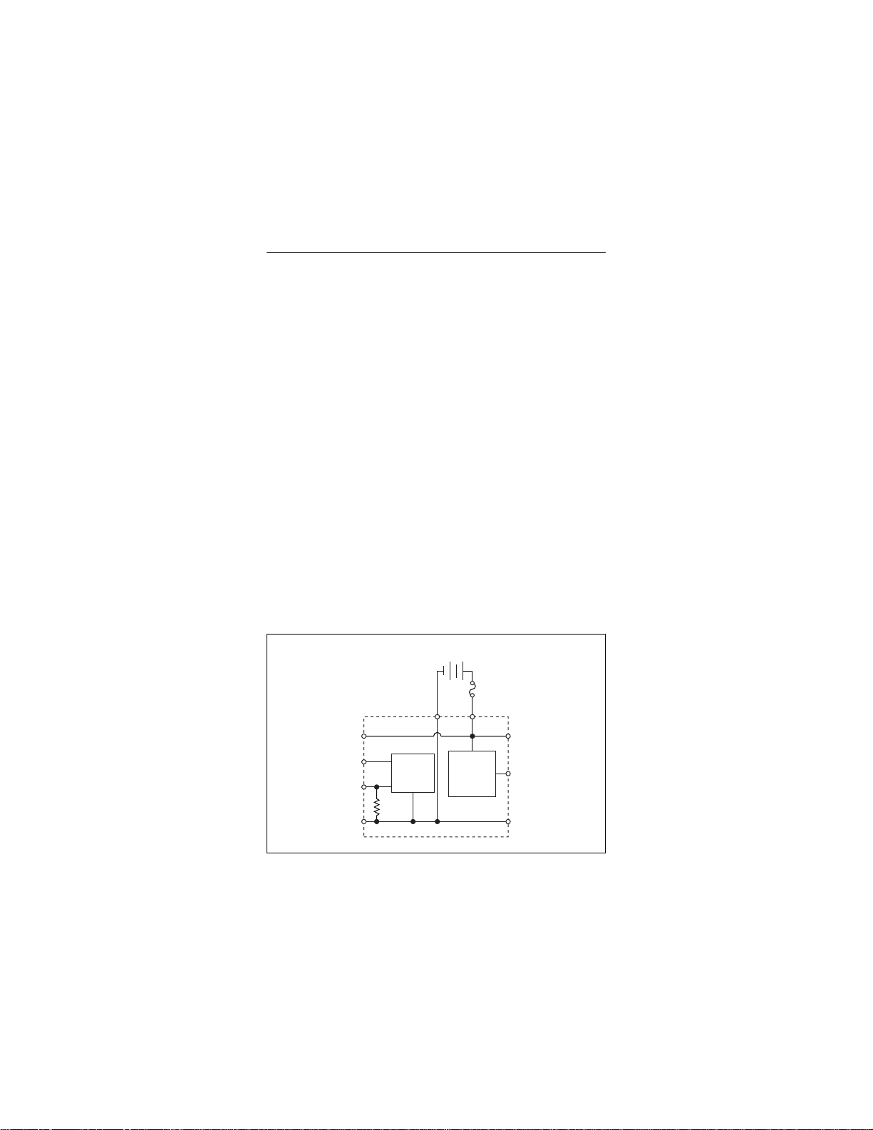
Wiring the [c]FP-AIO-600
–
10–30 VDC
External
Power Supply
V
COM
C
I
IN
V
IN
I
OUT
V
SUP
COM
Input
Circuitry
+
105 Ω
2 A max
V
SUP
Sourcing
Output
Circuitry
The FP-TB-x terminal base has connections for each FP-AIO-600
input and output channel, and for an external power supply to
power the current output channels and field devices. The cFP-CB-x
connector block provides the same connections for the
cFP-AIO-600. Each input channel has one input terminal for
voltage, V
these input terminals should be connected on each channel. Each
output channel has one output terminal for current, I
four input channels and all four output channels are referenced to
the COM terminals. The V and V
connected, as are the C and COM terminals.
Use a 10–30 VDC external power supply that provides at least
125 mA for the output channels. The power supply must provide
more current if you use it to power transducers or field devices.
Connect the external power supply to multiple V and V
terminals and to multiple C and COM terminals as needed to
ensure that the maximum current through any terminal is 2 A
or less.
Install a 125 mA minimum, 2 A maximum, fast-acting fuse at
each connected V and V
for the device connected to each channel to protect the module
and connected devices. Install a 63 mA, fast-acting fuse at each
connected I
document show fuses where appropriate.
, and one input terminal for current, IIN. Only one of
IN
. All
OUT
terminals are all internally
SUP
SUP
terminal. Select a fuse value suitable
SUP
terminal. The detailed wiring diagrams in this
IN
Figure 3. Basic Field Connection
FP-AIO-600 and cFP-AIO-600 4 ni.com
Artisan Technology Group - Quality Instrumentation ... Guaranteed | (888) 88-SOURCE | www.artisantg.com

Caution Do not connect both current and voltage inputs
to the same channel.
Table 1 lists the terminal assignments for the signals of each input
channel.
Table 1. Input Terminal Assignments
Inputs
Channel
V
IN
1
I
IN
2
V
SUP
COM
In 0 1 2 17 18
In 1 3 4 19 20
In 2 5 6 21 22
In 3 7 8 23 24
1
Install a 63 mA fast-acting fuse on each IIN terminal.
2
Install a 2 A maximum fast-acting fuse on each V
terminal.
SUP
Table 2 lists the terminal assignments for the signals of each output
channel.
Table 2. Output Terminal Assignments
Outputs
Channel
I
OUT
Out 0 9 25 10, 26
Out 1 11 27 12, 28
Out 2 13 29 14, 30
Out 3 15 31 16, 32
1
Install a 2 A maximum fast-acting fuse on each V
1
V
SUP
SUP
COM
terminal.
Caution Cascading power between two modules defeats
isolation between those modules.
Connecting Signals to the [c]FP-AIO-600
The [c]FP-AIO-600 has four single-ended input channels. All
four input channels share a common ground reference that is
isolated from other modules in the FieldPoint system.
© National Instruments Corp. 5 FP-AIO-600 and cFP-AIO-600
Artisan Technology Group - Quality Instrumentation ... Guaranteed | (888) 88-SOURCE | www.artisantg.com
Note The input and output channels of the
Filter
12-Bit
ADC
V
SUP
V
IN
COM
I
IN
V
C
To Next Channel
105 Ω
1.5 MΩ
V
SUP
V
IN
VC
To Analog
Input Circuitry
To Next Channel
1.5 MΩ
Input
Impedance
COM
[c]FP-AIO-600
Voltage
Source
+
–
I
IN
[c]FP-AIO-600 are not electrically isolated from
each other.
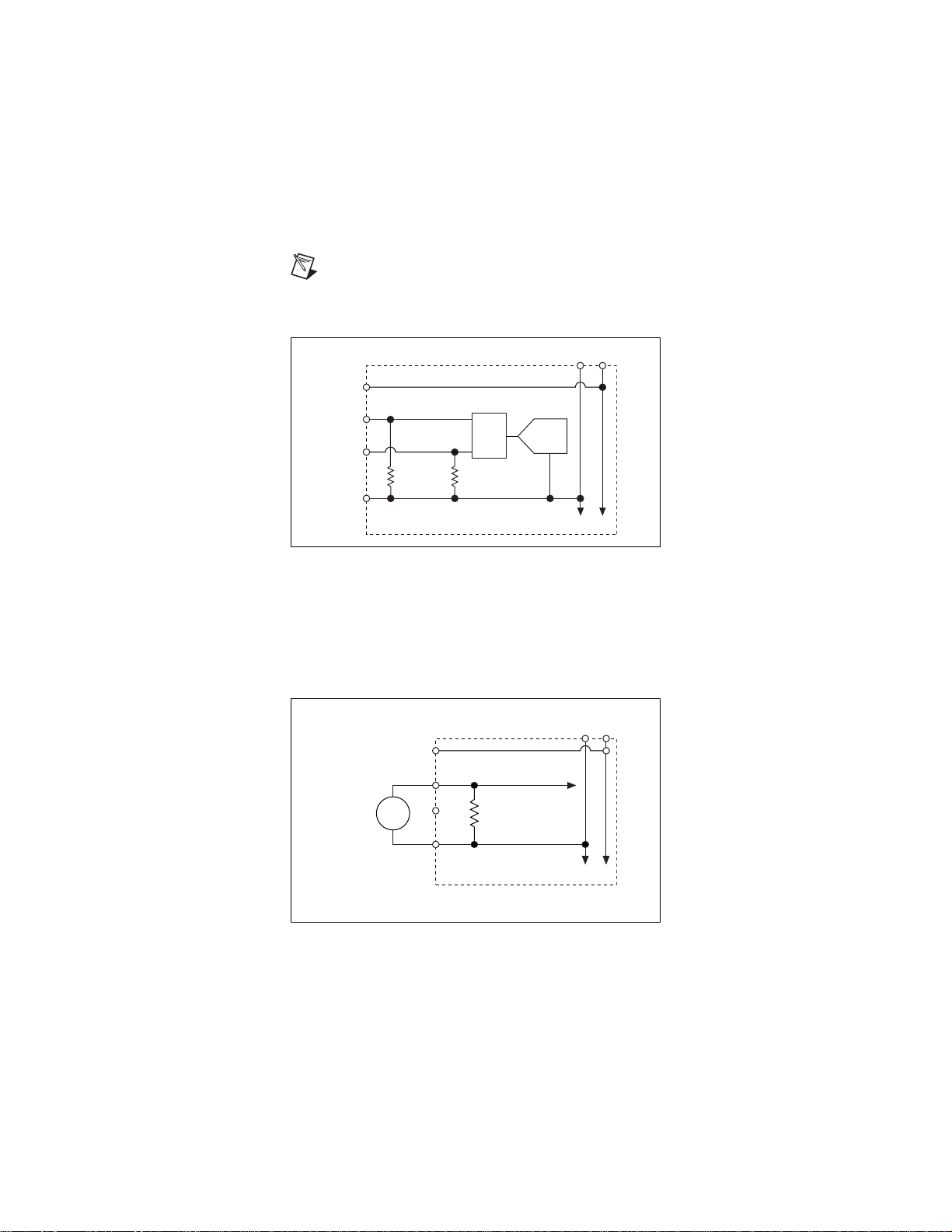
Figure 4 shows the input circuitry on a single input channel.
Figure 4. Input Circuitry on One Channel of the [c]FP-AIO-600
Voltage Inputs
The input ranges for voltage signals are 5, 10, 15, 30, 0–5,
0–10, 0–15, and 0–30 V. FieldPoint software accounts for the
20% overranging feature and shows the ranges accordingly.
Figure 5 shows how to connect a voltage source without an
external power supply to one input channel of the [c]FP-AIO-600.
Figure 5. Voltage Input without an External Power Supply
FP-AIO-600 and cFP-AIO-600 6 ni.com
Artisan Technology Group - Quality Instrumentation ... Guaranteed | (888) 88-SOURCE | www.artisantg.com

Figure 6 shows how to connect a voltage source with an external
V
SUP
V
IN
VC
To Analog
Input Circuitry
To Next Channel
COM
Powered
Voltage
Transducer
OUT
+
–
10–30 VDC
External
Power Supply
+
–
[c]FP-AIO-600
I
IN
2 A
Max
2 A
Max
V
C
V
SUP
V
IN
COM
[c]FP-AIO-600
I
IN
To Analog
Input Circuitry
To Next Channel
Current
Source
63 mA
power supply to one input channel of the [c]FP-AIO-600.
Figure 6. Voltage Input with an External Power Supply
Current Inputs
The input ranges for current sources are 20, 0–20, and 4–20 mA.
FieldPoint software accounts for the 20% overranging feature and
shows the ranges accordingly. Figure 7 shows how to connect a
current source without an external power supply to one input
channel of the [c]FP-AIO-600.
Figure 7. Current Input without an External Power Supply
© National Instruments Corp. 7 FP-AIO-600 and cFP-AIO-600
Artisan Technology Group - Quality Instrumentation ... Guaranteed | (888) 88-SOURCE | www.artisantg.com

Figure 8 shows how to connect a current source with an external
+
–
V
C
10–30 VDC
External
Power Supply
V
SUP
V
IN
COM
[c]FP-AIO-600
Loop-
Powered
Current
Transmitter
I
IN
To Analog
Input Circuitry
To Next Channel
2 A
Max
63 mA
power supply to one input channel of the [c]FP-AIO-600.
Figure 8. Current Input with an External Power Supply
Input Ranges
To prevent inaccurate readings, select an input range such that the
signal you are measuring does not exceed either end of the range.
Overranging
The [c]FP-AIO-600 has an overranging feature that measures 20%
beyond the nominal values of each range. For example, the actual
measurement limit of the 5 V range is 6.0 V. The overranging
feature enables the [c]FP-AIO-600 to compensate for field devices
with span errors of up to 20% of full scale. Also, the overranging
feature helps prevent errors caused by clipping.
Connecting the [c]FP-AIO-600 to a Load
The [c]FP-AIO-600 has four single-ended current output channels
that source current from a 10–30 VDC, 125 mA external power
supply. Sourcing current means that current flows out of the I
terminal into the load. All four output channels and their common
are isolated from the other modules in the FieldPoint system. The
four output channels are not isolated from the four input channels.
FP-AIO-600 and cFP-AIO-600 8 ni.com
Artisan Technology Group - Quality Instrumentation ... Guaranteed | (888) 88-SOURCE | www.artisantg.com
OUT

Note Add a 2 A max fuse to any V
V
SUP
I
OUT
COM
CV
To Next Channel
+–
10–30 VDC
External
Power Supply
2 A
Max
[c]FP-AIO-600
Load
Current
Source
Circuit
12-Bit
DAC
terminal in use.
SUP
Figure 9 shows how to connect one output channel of the
[c]FP-AIO-600 to a load.
Figure 9. [c]FP-AIO-600 Analog Output Circuit
Output Ranges
You can configure each channel independently for an output range
of 0–20 or 4 –20 mA. The default range setting for each channel is
0–20 mA, with the power-up output set to 0 mA. The
[c]FP-AIO-600 has overranging in each of these ranges, so
the full-scale ranges available are 0–21 mA and 3.5–21 mA.
Overranging enables the [c]FP-AIO-600 to compensate for span
and offset errors in field devices.
Open-Loop Detection
Each channel has a monitoring circuit that compares the actual
output current to the specified output current. If the [c]FP-AIO-600
cannot source the specified output current for one or more
channels, the monitoring circuits turn on a red STATUS LED for
each affected channel and report the error condition to the network
module. Generally, the error condition is caused by an open current
loop—either the load device or the external power supply is
disconnected. However, the monitoring circuit also detects errors
caused by load impedances that are too high and by external power
supply voltages that are too low. For more information, refer to the
Specifications section.
© National Instruments Corp. 9 FP-AIO-600 and cFP-AIO-600
Artisan Technology Group - Quality Instrumentation ... Guaranteed | (888) 88-SOURCE | www.artisantg.com

If the output of a [c]FP-AIO-600 channel is set to 0 mA, the
monitoring circuit does not register an error condition because the
[c]FP-AIO-600 can always source zero current, even to an open
loop. Leave any unused and unwired channels in the default state
to avoid error conditions.
Short-Circuit Protection
Each I
circuits. One or more channel outputs can be short-circuited
indefinitely without causing damage or improper operation to the
channel, as long as the maximum loop supply does not exceed
30 VDC.
terminal of the [c]FP-AIO-600 is protected against short
OUT
Status Indicators
The [c]FP-AIO-600 has two green status LEDs, POWER and
READY. After you install the [c]FP-AIO-600 onto a terminal base
or backplane and apply power to the connected network module,
the green POWER indicator lights and the [c]FP-AIO-600
informs the network module of its presence. When the network
module recognizes the [c]FP-AIO-600, it sends initial
configuration information to the [c]FP-AIO-600. After the
[c]FP-AIO-600 receives this initial information, the green
READY indicator lights and the module is in normal operating
mode.
In addition to the green POWER and READY indicators, each
output channel has a red, numbered error status indicator. For more
information, refer to the Open-Loop Detection section.
Upgrading the FieldPoint Firmware
You may need to upgrade the FieldPoint firmware when you add
new I/O modules to the FieldPoint system. For information on
determining which firmware you need and how to upgrade the
firmware, go to
ni.com/info and enter fpmatrix.
Isolation and Safety Guidelines
Caution Read the following information before
attempting to connect the [c]FP-AIO-600 to any circuits
that may contain hazardous voltages.
FP-AIO-600 and cFP-AIO-600 10 ni.com
Artisan Technology Group - Quality Instrumentation ... Guaranteed | (888) 88-SOURCE | www.artisantg.com

This section describes the isolation of the [c]FP-AIO-600 and its
compliance with international safety standards. The field wiring
connections are isolated from the backplane and the inter-module
communication bus. The isolation barriers in the module provide
250 V
by 2,300 V
provides double insulation (compliant with IEC 61010-1) for
working voltages of 250 V
Measurement Category II continuous isolation, verified
rms
, 5 s dielectric withstand test. The [c]FP-AIO-600
rms
1
. Safety standards (such as those
rms
published by UL and IEC) require the use of double insulation
between hazardous voltages and any human-accessible parts or
circuits.
Never try to use any isolation product between human-accessible
parts (such as DIN rails or monitoring stations) and circuits that
can be at hazardous potentials under normal conditions, unless the
product is specifically designed for such an application, as is the
[c]FP-AIO-600.
Even though the [c]FP-AIO-600 is designed to handle applications
with hazardous potentials, follow these guidelines to ensure a safe
total system:
• There is no isolation between channels on the [c]FP-AIO-600.
If a hazardous voltage is present on any channel, all channels
are considered hazardous. Make sure that all other devices and
circuits connected to the module are properly insulated from
human contact.
•Do not share the external supply voltages (the V and C
terminals) with other devices (including other FieldPoint
devices), unless those devices are isolated from human contact.
• For Compact FieldPoint, you must connect the protective earth
(PE) ground terminal on the cFP-BP-x backplane to the system
safety ground. The backplane PE ground terminal has the
following symbol stamped beside it: . Connect the
backplane PE ground terminal to the system safety ground
using 14 AWG (1.6 mm) wire with a ring lug. Use the 5/16 in.
panhead screw shipped with the backplane to secure the ring
lug to the backplane PE ground terminal.
• As with any hazardous voltage wiring, make sure that all
wiring and connections meet applicable electrical codes and
commonsense practices. Mount terminal bases and backplanes
1
Working voltage is defined as the signal voltage plus the common-mode voltage.
Common-mode voltage is the voltage of the module with respect to ground.
© National Instruments Corp. 11 FP-AIO-600 and cFP-AIO-600
Artisan Technology Group - Quality Instrumentation ... Guaranteed | (888) 88-SOURCE | www.artisantg.com

in an area, position, or cabinet that prevents accidental or
unauthorized access to wiring that carries hazardous voltages.
•Do not use the [c]FP-AIO-600 as the only isolating barrier
between human contact and working voltages higher than
rms
.
250 V
• Operate the [c]FP-AIO-600 only at or below Pollution
Degree 2. Pollution Degree 2 means that only nonconductive
pollution occurs in most cases. Occasionally, however, a
temporary conductivity caused by condensation must be
expected.
• Operate the [c]FP-AIO-600 at or below Measurement
Category II. Measurement Category II is for measurements
performed on circuits directly connected to the low-voltage
installation. This category refers to local-level distribution,
such as that provided by a standard wall outlet.
Safety Guidelines for Hazardous Locations
The cFP-AIO-600 is suitable for use in Class I, Division 2, Groups
A, B, C, D, T4 hazardous locations; Class I, Zone 2, AEx nA IIC
T4 and Ex nA IIC T4 hazardous locations; and nonhazardous
locations only. Follow these guidelines if you are installing the
cFP-AIO-600 in a potentially explosive environment. Failing to
follow these guidelines may result in serious injury or death.
Caution Make sure that all products you use in hazardous
locations are certified for such use. Refer to the product
label or visit
model number or product line, and click the appropriate
link in the Certification column.
ni.com/certification, search by
Caution Do not disconnect I/O-side wires or connectors
unless power has been switched off or the area is known
to be nonhazardous.
Caution Do not remove modules unless power has been
switched off or the area is known to be nonhazardous.
Caution Substitution of components may impair
suitability for Class I, Division 2.
Caution For Zone 2 applications, install the Compact
FieldPoint system in an enclosure rated to at least IP 54
as defined by IEC 60529 and EN 60529.
FP-AIO-600 and cFP-AIO-600 12 ni.com
Artisan Technology Group - Quality Instrumentation ... Guaranteed | (888) 88-SOURCE | www.artisantg.com

Caution For Zone 2 applications, install a protection
device across the external power supply and the COM
terminal. The device must prevent the external power
supply voltage from exceeding 42 V if there is a transient
overvoltage condition.
Special Conditions for Hazardous Locations Use in Europe
The cFP-AIO-600 has been evaluated as EEx nC IIC T4 equipment
under DEMKO Certificate No. 03 ATEX 0251502X. Each module
is marked II 3G and is suitable for use in Zone 2 hazardous
locations.
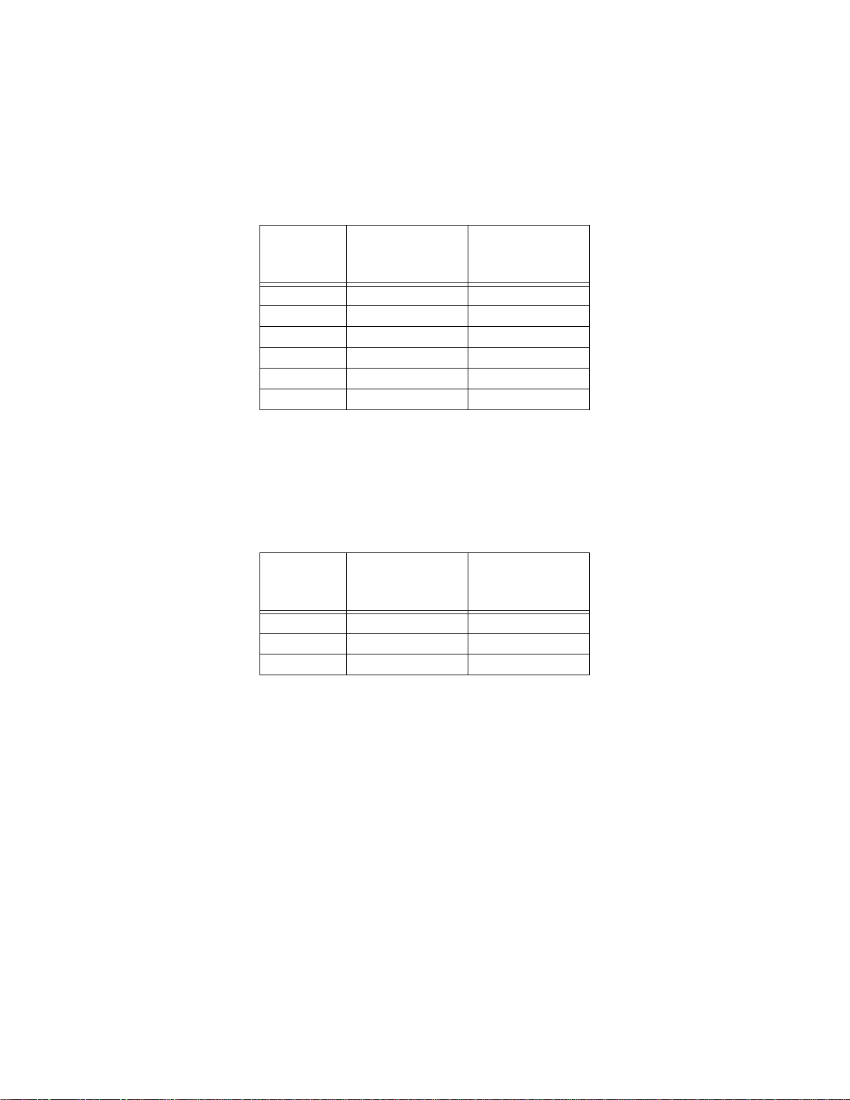
Specifications
The following specifications are maximums for the range –40 to
70 °C unless otherwise noted. Specifications are subject to change
without notice.
Input and Output Characteristics
Number of input channels.................4
Number of output channels...............4
ADC resolution................................. 12 bits
Type of ADC.....................................Successive approximation
DAC resolution .................................12 bits
Type of DAC..................................... R-2R
Hardware update rate
(all 8 channels)..................................1.7 kHz (588 s period)
Voltage Inputs
Effective resolution...........................11.3 bits
Input impedance................................ 1.5 M
Signal input bandwidth (–3 dB)........350 Hz
Voltage input accuracy by voltage input range
Accuracy
Voltage Input
Range (with
Overranging)
0–6 V 0.04%; 0.15% 0.16%; 0.25%
0–12 V 0.04%; 0.12% 0.16%; 0.17%
© National Instruments Corp. 13 FP-AIO-600 and cFP-AIO-600
at 15 to 35
(% of Reading;
% of Full Scale)
°C
Accuracy
at –40 to 70
(% of Reading;
% of Full Scale)
°C
Artisan Technology Group - Quality Instrumentation ... Guaranteed | (888) 88-SOURCE | www.artisantg.com
Accuracy
Voltage Input
Range (with
Overranging)
0–18 V 0.04%; 0.10% 0.16%; 0.13%
0–36 V 0.04%; 0.09% 0.16%; 0.10%
6 V 0.04%; 0.12% 0.19%; 0.17%
12 V 0.04%; 0.10% 0.19%; 0.12%
18 V 0.04%; 0.09% 0.19%; 0.11%
36 V 0.04%; 0.08% 0.19%; 0.09%
at 15 to 35
(% of Reading;
% of Full Scale)
°C
Accuracy
at –40 to 70
(% of Reading;
% of Full Scale)
Current Inputs
Effective resolution...........................11.3 bits
Input impedance................................ 105
Overcurrent protection100 mA
Overvoltage protection 10 V
Signal input bandwidth (–3 dB)........350 Hz
Current input accuracy by current input range
Accuracy
Current Input
Range (with
Overranging)
0–24 mA 0.07%; 0.08% 0.29%; 0.08%
3.5–24 mA 0.07%; 0.10% 0.29%; 0.10%
24 mA 0.07%; 0.08% 0.32%; 0.08%
at 15 to 35
(% of Reading;
% of Full Scale)
°C
Accuracy
at –40 to 70
(% of Reading;
% of Full Scale)
°C
°C
FP-AIO-600 and cFP-AIO-600 14 ni.com
Artisan Technology Group - Quality Instrumentation ... Guaranteed | (888) 88-SOURCE | www.artisantg.com

Current Outputs
Output range .....................................0–20 or 4–20 mA,
Type .................................................. Current source, external
External power supply......................10
Internal voltage drop.........................3 V
Resistive load ....................................Up to 1 k with 24 V
Protection.......................................... Short-circuit and
Default power-up state......................0 mA
Current output accuracy by current output range
Accuracy
Current Outp ut
Range (with
Overranging)
0–21 mA 0.03%; 0.13% 0.14%; 0.2%
3.5–21 mA 0.03%; 0.16% 0.14%; 0.23%
at 15 to 35
(% of Output Value;
% of Full Scale)
programmable
(0–21 or 3.5–21 mA
with overranging)
power required
–30 VDC, 125 mA for
4 output channels
power supply
open-circuit
°C
at –40 to 70
(% of Output Value;
% of Full Scale)
1
Accuracy
°C
Dynamic Characteristics
Hardware update rate ........................ 1,700 updates/s
Slew rate ...........................................0.4 mA/s
Physical Characteristics
Indicators ..........................................Green POWER and
Weight
FP-AIO-600................................ 141 g (4.9 oz)
cFP-AIO-600..............................111 g (3.9 oz)
1
Maximum load resistance = (Supply voltage – Internal voltage drop)/0.021 A
© National Instruments Corp. 15 FP-AIO-600 and cFP-AIO-600
READY indicators, and
4 red output indicators
Artisan Technology Group - Quality Instrumentation ... Guaranteed | (888) 88-SOURCE | www.artisantg.com

Power Requirements
Power from network module ............ 600 mW
Isolation Voltage
Channel-to-ground isolation
Continuous ................................. 250 V
, Measurement
rms
Category II
Dielectric withstand....................2,300 V
rms
, 5 s
Channel-to-channel isolation............None
Environmental
FieldPoint modules are intended for indoor use only. For outdoor
use, they must be mounted inside a sealed enclosure.
Operating temperature ......................–40 to 70 °C
Storage temperature..........................–55 to 85 °C
Humidity...........................................10 to 90% RH,
noncondensing
Maximum altitude.............................2,000 m; at higher altitudes
the isolation voltage ratings
must be lowered
Pollution Degree ...............................2
Shock and Vibration
These specifications apply only to the cFP-AIO-600.
NI recommends Compact FieldPoint if your application is subject
to shock and vibration.
Operating vibration, random
(IEC 60068-2-64)..............................10 –500 Hz, 5 g
Operating vibration, sinusoidal
(IEC 60068-2-6)................................10 –500 Hz, 5 g
Operating shock
(IEC 60068-2-27)..............................50 g, 3 ms half sine,
18 shocks at 6 orientations;
30 g, 11 ms half sine,
18 shocks at 6 orientations
rms
FP-AIO-600 and cFP-AIO-600 16 ni.com
Artisan Technology Group - Quality Instrumentation ... Guaranteed | (888) 88-SOURCE | www.artisantg.com

Safety
This product is designed to meet the requirements of the following
standards of safety for electrical equipment for measurement,
control, and laboratory use:
• IEC 61010-1, EN-61010-1
• UL 61010-1, CAN/CSA-C22.2 No. 61010-1
Note For UL and other safety certifications, refer to the
product label or visit
ni.com/certification, search
by model number or product line, and click the
appropriate link in the Certification column.
Electromagnetic Compatibility
This product is designed to meet the requirements of the following
standards of EMC for electrical equipment for measurement,
control, and laboratory use:
• EN 61326 EMC requirements; Industrial Immunity
• EN 55011 Emissions; Group 1, Class A
• CE, C-Tick, ICES, and FCC Part 15 Emissions; Class A
Note For EMC compliance, operate this device to
product documentation.
CE Compliance
This product meets the essential requirements of applicable
European Directives, as amended for CE marking, as follows:
• 73/23/EEC; Low-Voltage Directive (safety)
• 89/336/EEC; Electromagnetic Compatibility Directive (EMC)
Note Refer to the Declaration of Conformity (DoC) for
this product for any additional regulatory compliance
information. To obtain the DoC for this product, visit
ni.com/certification, search by model number or
product line, and click the appropriate link in the
Certification column.
© National Instruments Corp. 17 FP-AIO-600 and cFP-AIO-600
Artisan Technology Group - Quality Instrumentation ... Guaranteed | (888) 88-SOURCE | www.artisantg.com

Waste Electrical and Electronic Equipment (WEEE)
109.5 mm
(4.31 in.)
91.44 mm
(3.60 in.)
107.19 mm
(4.22 in.)
EU Customers At the end of their life cycle, all products
must be sent to a WEEE recycling center. For more
information about WEEE recycling centers and
National Instruments WEEE initiatives, visit
ni.com/environment/weee.htm.
Mechanical Dimensions
Figure 10 shows the mechanical dimensions of the FP-AIO-600
installed on a terminal base. If you are using the cFP-AIO-600,
refer to your Compact FieldPoint controller user manual for the
dimensions and cabling clearance requirements of the Compact
FieldPoint system.
Figure 10. FP-AIO-600 Mechanical Dimensions
FP-AIO-600 and cFP-AIO-600 18 ni.com
Artisan Technology Group - Quality Instrumentation ... Guaranteed | (888) 88-SOURCE | www.artisantg.com

Where to Go for Support
For more information about setting up the FieldPoint system, refer
to these National Instruments documents:
• FieldPoint network module user manual
• Other FieldPoint I/O module operating instructions
• FieldPoint terminal base and connector block operating
instructions
ni.com/support for the most current manuals, examples,
Go to
and troubleshooting information.
For telephone support in the United States, create your service
request at ni.com/ask and follow the calling instructions or dial
512 795 8248. For telephone support outside the United States,
contact your local branch office:
Australia 1800 300 800, Austria 43 0 662 45 79 90 0,
Belgium32027570020, Brazil551132623599,
Canada 800 433 3488, China 86 21 6555 7838,
Czech Republic 420 224 235 774, Denmark 45 45 76 26 00,
Finland 385 0 9 725 725 11, France 33 0 1 48 14 24 24,
Germany 49 0 89 741 31 30, India 91 80 41190000,
Israel972036393737, Italy3902413091,
Japan 81 3 5472 2970, Korea 82 02 3451 3400,
Lebanon 961 0 1 33 28 28, Malaysia 1800 887710,
Mexico 01 800 010 0793, Netherlands 31 0 348 433 466,
NewZealand0800553322, Norway47066907660,
Poland 48 22 3390150, Portugal 351 210 311 210,
Russia 7 095 783 68 51, Singapore 1800 226 5886,
Slovenia 386 3 425 4200, South Africa 27 0 11 805 8197,
Spain34916400085, Sweden460858789500,
Switzerland 41 56 200 51 51, Taiwan 886 02 2377 2222,
Thailand 662 278 6777, United Kingdom 44 0 1635 523545
© National Instruments Corp. 19 FP-AIO-600 and cFP-AIO-600
Artisan Technology Group - Quality Instrumentation ... Guaranteed | (888) 88-SOURCE | www.artisantg.com

National Instruments, NI, ni.com, and LabVIEW are trademarks of National Instruments Corporation. Refer to the
Terms of Use section on
product and company names mentioned herein are trademarks or trade names of their respective companies.
For patents covering National Instruments products, refer to the appropriate location: Help»Patents in your software,
the
patents.txt file on your CD, or ni.com/p atents.
© 2003–2009 National Instruments Corp. All rights reserved.
ni.com/legal for more information about National Instruments trademarks. Other
373614D-01 Nov09
Artisan Technology Group - Quality Instrumentation ... Guaranteed | (888) 88-SOURCE | www.artisantg.com

Artisan Technology Group is your source for quality
new and certied-used/pre-owned equipment
• FAST SHIPPING AND
DELIVERY
• TENS OF THOUSANDS OF
IN-STOCK ITEMS
• EQUIPMENT DEMOS
• HUNDREDS OF
MANUFACTURERS
SUPPORTED
• LEASING/MONTHLY
RENTALS
• ITAR CERTIFIED
SECURE ASSET SOLUTIONS
SERVICE CENTER REPAIRS
Experienced engineers and technicians on staff
at our full-service, in-house repair center
Instra
Remotely inspect equipment before purchasing with
our interactive website at www.instraview.com
Contact us: (888) 88-SOURCE | sales@artisantg.com | www.artisantg.com
SM
REMOTE INSPECTION
View
WE BUY USED EQUIPMENT
Sell your excess, underutilized, and idle used equipment
We also offer credit for buy-backs and trade-ins
www.artisantg.com/WeBuyEquipment
LOOKING FOR MORE INFORMATION?
Visit us on the web at www.artisantg.com for more
information on price quotations, drivers, technical
specications, manuals, and documentation
 Loading...