


GETTING STARTED GUIDE
NI 9244
3 AI/1 Neutral, 400 Vrms L-N/690 Vrms L-L,
24 Bit, 50 kS/s/ch Simultaneous
This document explains how to connect to the NI 9244.
Note Before you begin, complete the software and
hardware installation procedures in your chassis
documentation.
Note The guidelines in this document are specific to
the NI 9244. The other components in the system might
not meet the same safety ratings. Refer to the
documentation for each component in the system to
determine the safety and EMC ratings for the entire
system.
Safety Guidelines
Operate the NI 9244 only as described in this document.
Caution Do not operate the NI 9244 in a manner not
specified in this document. Product misuse can result in
a hazard. You can compromise the safety protection
built into the product if the product is damaged in any
way. If the product is damaged, return it to NI for
repair.
2 | ni.com | NI 9244 Getting Started Guide

Hazardous Voltage This icon denotes a warning
advising you to take precautions to avoid electrical
shock.
Safety Voltages
Connect only voltages that are within the following limits.
Maximum working voltage, channel-to-earth ground
Up to 2,000 m altitude
Continuous 400 Vrms,
Measurement Category III
Up to 5,000 m altitude
Continuous 400 Vrms,
Measurement Category II or
300 Vrms,
Measurement Category III
Division 2 and Zone 2 hazardous locations applications
Channel-to-earth
ground
300 Vrms,
Measurement Category III
Measurement Category II is for measurements performed on
circuits directly connected to the electrical distribution system.
NI 9244 Getting Started Guide | © National Instruments | 3
This category refers to local-level electrical distribution, such as
that provided by a standard wall outlet, for example, 115 V for
U.S. or 230 V for Europe.
Measurement Category III is for measurements performed in the
building installation at the distribution level. This category refers
to measurements on hard-wired hardware such as hardware in
fixed installations, distribution boards, and circuit breakers. Other
examples are wiring, including cables, bus bars, junction boxes,
switches, socket outlets in the fixed installation, and stationary
motors with permanent connections to fixed installations.
Caution Do not connect the NI 9244 to signals or use
for measurements within Measurement Category IV.
Safety Guidelines for Hazardous Voltages
If hazardous voltages are connected to the device, take the
following precautions. A hazardous voltage is a voltage greater
than 42.4 Vpk voltage or 60 VDC to earth ground.
Caution Ensure that hazardous voltage wiring is
performed only by qualified personnel adhering to local
electrical standards.
4 | ni.com | NI 9244 Getting Started Guide
Caution Do not mix hazardous voltage circuits and
human-accessible circuits on the same module.
Caution Ensure that devices and circuits connected to
the module are properly insulated from human contact.
Caution When module terminals are hazardous
voltage LIVE (>42.4 Vpk/60 VDC), you must ensure
that devices and circuits connected to the module are
properly insulated from human contact. You must use
the NI 9969 connector backshell kit to ensure that the
terminals are not accessible.
Safety Guidelines for Hazardous Locations
The NI 9244 is suitable for use in Class I, Division 2, Groups A,
B, C, D, T4 hazardous locations; Class I, Zone 2, AEx nA IIC T4
and Ex nA IIC T4 hazardous locations; and nonhazardous
locations only. Follow these guidelines if you are installing the
NI 9244 in a potentially explosive environment. Not following
these guidelines may result in serious injury or death.
Caution Do not disconnect I/O-side wires or
connectors unless power has been switched off or the
area is known to be nonhazardous.
NI 9244 Getting Started Guide | © National Instruments | 5

Caution Do not remove modules unless power has
been switched off or the area is known to be
nonhazardous.
Caution Substitution of components may impair
suitability for Class I, Division 2.
Caution For Division 2 and Zone 2 applications,
install the system in an enclosure rated to at least IP54
as defined by IEC/EN 60079-15.
Special Conditions for Hazardous Locations Use in
Europe and Internationally
The NI 9244 has been evaluated as Ex nA IIC T4 Gc equipment
under DEMKO Certificate No. 12 ATEX 1202658X and is
IECEx UL 14.0089X certified. Each NI 9244 is marked II 3G
and is suitable for use in Zone 2 hazardous locations, in ambient
temperatures of -40 °C ≤ Ta ≤ 70 °C. If you are using the NI 9244
in Gas Group IIC hazardous locations, you must use the device in
an NI chassis that has been evaluated as Ex nC IIC T4, Ex IIC
T4, Ex nA IIC T4, or Ex nL IIC T4 equipment.
6 | ni.com | NI 9244 Getting Started Guide
Caution The system shall only be used in an area of
not more than Pollution Degree 2, as defined in
IEC 60664-1.
Caution The system shall be mounted in an
ATEX/IECEx-certified enclosure with a minimum
ingress protection rating of at least IP54 as defined in
IEC/EN 60079-15.
Caution The enclosure must have a door or cover
accessible only by the use of a tool.
Electromagnetic Compatibility Guidelines
This product was tested and complies with the regulatory
requirements and limits for electromagnetic compatibility (EMC)
stated in the product specifications. These requirements and
limits provide reasonable protection against harmful interference
when the product is operated in the intended operational
electromagnetic environment.
This product is intended for use in industrial locations. However,
harmful interference may occur in some installations, when the
product is connected to a peripheral device or test object, or if the
NI 9244 Getting Started Guide | © National Instruments | 7
product is used in residential or commercial areas. To minimize
interference with radio and television reception and prevent
unacceptable performance degradation, install and use this
product in strict accordance with the instructions in the product
documentation.
Furthermore, any changes or modifications to the product not
expressly approved by National Instruments could void your
authority to operate it under your local regulatory rules.
Special Conditions for Marine Applications
Some products are Lloyd’s Register (LR) Type Approved for
marine (shipboard) applications. To verify Lloyd’s Register
certification for a product, visit ni.com/certification and search
for the LR certificate, or look for the Lloyd’s Register mark on
the product.
Caution In order to meet the EMC requirements for
marine applications, install the product in a shielded
enclosure with shielded and/or filtered power and
input/output ports. In addition, take precautions when
designing, selecting, and installing measurement probes
and cables to ensure that the desired EMC performance
is attained.
8 | ni.com | NI 9244 Getting Started Guide
Preparing the Environment
Ensure that the environment in which you are using the NI 9244
meets the following specifications.
Operating temperature
(IEC 60068-2-1, IEC 60068-2-2)
-40 °C to 70 °C
Operating humidity
(IEC 60068-2-78)
10% RH to 90% RH,
noncondensing
Pollution Degree 2
Maximum altitude 5,000 m
Indoor use only.
Note Refer to the device datasheet on ni.com/manuals
for complete specifications.
NI 9244 Getting Started Guide | © National Instruments | 9

NI 9244 Pinout
AI0
AI1
AI2
Neutral
0
1
2
3
10 | ni.com | NI 9244 Getting Started Guide
Table 1. Signal Descriptions
Signal Description
AI Analog input signal connection referenced to the Neutral
signal
Neutral Referenced, single-ended analog input connection
Connecting Phase Measurements
The NI 9244 accepts three-phase and single-phase measurement
configuration.
Three-Phase Measurement Configurations
NI recommends the following three-phase connection types.
NI 9244 Getting Started Guide | © National Instruments | 11

4-Wire WYE Measurement Configuration
NI 9244
AI0
Phase A
Phase B
Phase C
Neutral
Neutral
AI2
AI1
12 | ni.com | NI 9244 Getting Started Guide

High-Leg Delta Measurement Configuration
NI 9244
AI0
Phase A
Phase B
Phase C
Neutral
AI2
AI1
Neutral
NI 9244 Getting Started Guide | © National Instruments | 13

3-Wire Delta Measurement Configuration
NI 9244
AI0
Phase A
Phase B
Phase C
AI2
AI1
14 | ni.com | NI 9244 Getting Started Guide
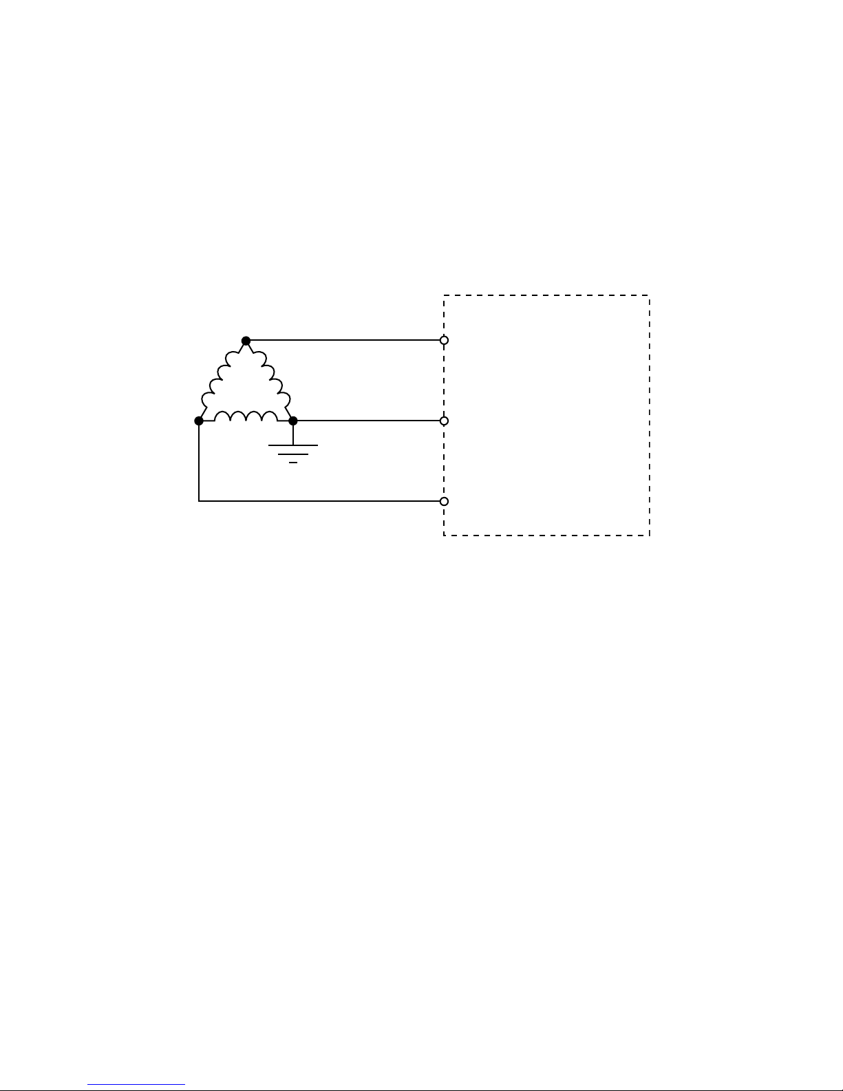
Corner Grounded 2-Wire Delta Measurement
Configuration
NI 9244
AI0
Phase A
Phase B
Phase C
AI2
AI1
The 9244 cannot measure the entire tolerance range or high crest
factor signals on 690 Vrms systems in this configuration.
Connecting Single-Phase Measurement
Configurations
NI recommends the following single-phase connection types.
NI 9244 Getting Started Guide | © National Instruments | 15

3-Wire Measurement (Split Phase) Configuration
NI 9244
AI0
Neutral
AI1
2-Wire Measurement
NI 9244
AI0
Neutral
16 | ni.com | NI 9244 Getting Started Guide

Connection Guidelines
• You must use 2-wire ferrules to create a secure connection
when connecting more than one wire to a single terminal on
the NI 9244.
• Make sure that devices you connect to the NI 9244 are
compatible with the module specifications.
To ensure that measurements to chassis ground are correct, NI
recommends connecting the chassis to earth ground using the
chassis grounding screw. Refer to your chassis manual for
information about connecting the chassis to earth ground.
High-Vibration Application Connections
If your application is subject to high vibration, NI recommends
that you follow these guidelines to protect connections to the
NI 9244:
• Use ferrules to terminate wires to the detachable connector.
• Use the NI 9969 backshell kit.
NI 9244 Getting Started Guide | © National Instruments | 17
Wiring the NI 9969
Caution For safe operation with hazardous voltages,
you must use the NI 9969 Connector Backshell with
the 4-terminal connector on the NI 9244.
Complete the appropriate procedure for each wire gauge.
Installing the NI 9969 Using 12 AWG to 14 AWG Wire
What to Use
• NI 9969 backshell
• 12 AWG to 14 AWG wire
• Smallest strain-relief piece
• Screwdriver
18 | ni.com | NI 9244 Getting Started Guide
What to Do
1
2
1. Route wires under the smallest strain-relief piece.
2. Secure the smallest strain-relief piece and the backshell in
place using captive screws.
NI 9244 Getting Started Guide | © National Instruments | 19

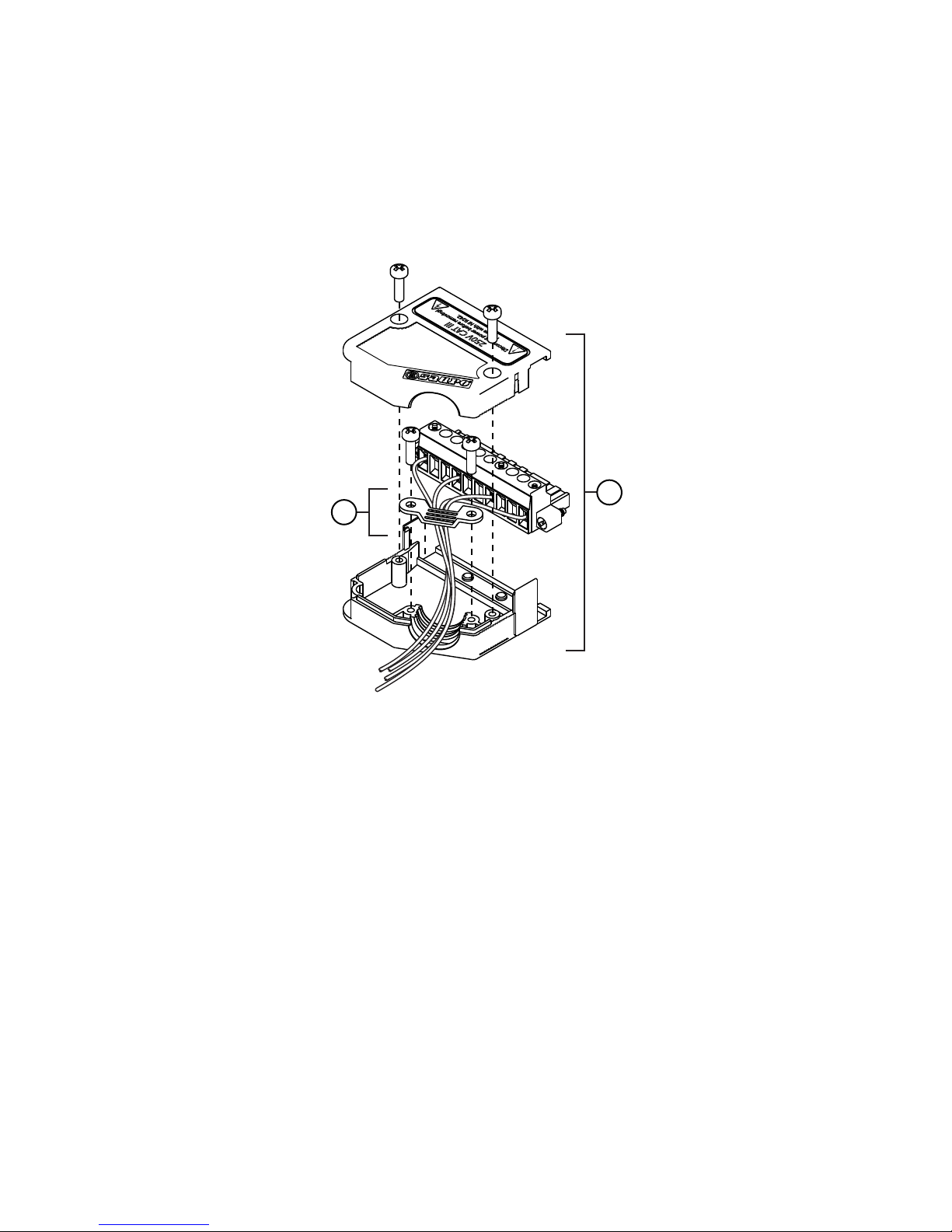
Installing the NI 9969 Using 16 AWG Wire
What to Use
• NI 9969 backshell
• 16 AWG wire
• Small and large strain-relief pieces
• Screwdriver
20 | ni.com | NI 9244 Getting Started Guide

What to Do
1
2
1. Route wires between the two strain-relief pieces, with the
small strain-relief piece on top of the wires and the large
strain-relief piece underneath the wires.
2. Secure the strain-relief pieces and the backshell in place
using captive screws.
NI 9244 Getting Started Guide | © National Instruments | 21

Installing the NI 9969 Using 18 AWG to 24 AWG Wire
What to Use
• NI 9969 backshell
• 18 AWG to 24 AWG wire
• Largest strain-relief piece
• Screwdriver
22 | ni.com | NI 9244 Getting Started Guide

What to Do
1
2
1. Route wires under the largest strain-relief piece.
2. Secure the largest strain-relief piece and the backshell in
place using captive screws.
NI 9244 Getting Started Guide | © National Instruments | 23

Converting L-N Measurements to L-Earth
To convert L-N measurements to L-Earth values, add the neutral
channel reading to each AI channel reading.
Refer to the following equation for an example of converting L-N
measurements to L-Earth.
Line to Earth = AIx + Neutral
where
AIx is the analog input channel reading
Neutral is the Neutral channel reading
Converting L-N Measurements to L-L
To convert L-N measurements to L-L values, calculate the
voltage difference between the AI channels using your
application software.
Refer to the following equation for an example of converting L-N
measurements to L-L.
Phase A to Phase B Voltage = AI0 - AI1
24 | ni.com | NI 9244 Getting Started Guide

where
AI0 is the reading from Phase A
AI1 is the reading from Phase B
NI 9244 Getting Started Guide | © National Instruments | 25
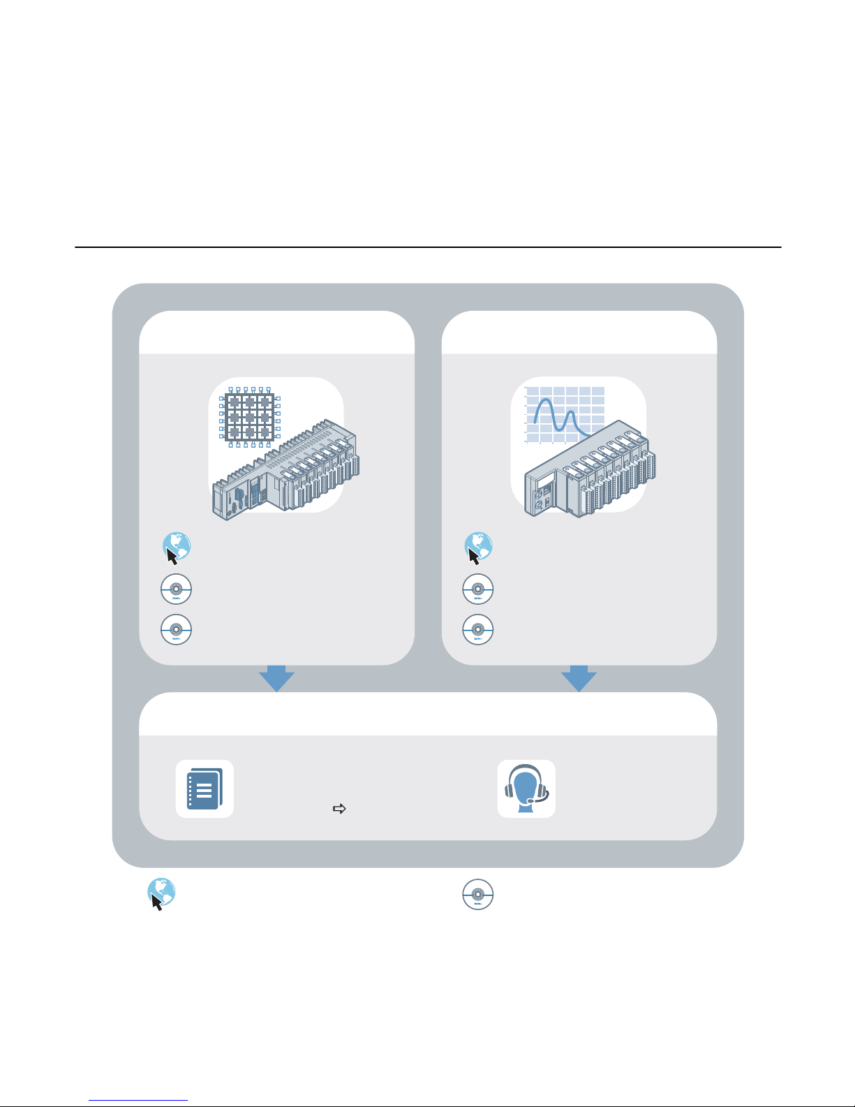
Where to Go Next
CompactRIO
NI CompactDAQ
Located at ni.com/manuals
RELATED INFORMATION
C Series Documentation
& Resources
ni.com/info cseriesdoc
Services
ni.com/services
Installs with the software
NI 9244 Datasheet
NI-RIO Help
LabVIEW FPGA Help
NI 9244 Datasheet
NI-DAQmx Help
LabVIEW Help
26 | ni.com | NI 9244 Getting Started Guide

Worldwide Support and Services
The NI website is your complete resource for technical support.
At ni.com/support, you have access to everything from
troubleshooting and application development self-help resources
to email and phone assistance from NI Application Engineers.
Visit ni.com/services for NI Factory Installation Services, repairs,
extended warranty, and other services.
Visit ni.com/register to register your NI product. Product
registration facilitates technical support and ensures that you
receive important information updates from NI.
A Declaration of Conformity (DoC) is our claim of compliance
with the Council of the European Communities using the
manufacturer’s declaration of conformity. This system affords the
user protection for electromagnetic compatibility (EMC) and
product safety. You can obtain the DoC for your product by
visiting ni.com/certification. If your product supports calibration,
you can obtain the calibration certificate for your product at
ni.com/calibration.
NI 9244 Getting Started Guide | © National Instruments | 27

NI corporate headquarters is located at
11500 North Mopac Expressway, Austin, Texas, 78759-3504. NI
also has offices located around the world. For telephone support
in the United States, create your service request at ni.com/support
or dial 1 866 ASK MYNI (275 6964). For telephone support
outside the United States, visit the Worldwide Offices section of
ni.com/niglobal to access the branch office websites, which
provide up-to-date contact information, support phone numbers,
email addresses, and current events.
Refer to the NI Trademarks and Logo Guidelines at ni.com/trademarks for information on NI
trademarks. Other product and company names mentioned herein are trademarks or trade names
of their respective companies. For patents covering NI products/technology, refer to the
appropriate location: Help»Patents in your software, the patents.txt file on your media, or the
National Instruments Patent Notice at ni.com/patents. You can find information about end-user
license agreements (EULAs) and third-party legal notices in the readme file for your NI product.
Refer to the Export Compliance Information at ni.com/legal/export-compliance for the NI
global trade compliance policy and how to obtain relevant HTS codes, ECCNs, and other import/
export data. NI MAKES NO EXPRESS OR IMPLIED WARRANTIES AS TO THE ACCURACY OF
THE INFORMATION CONTAINED HEREIN AND SHALL NOT BE LIABLE FOR ANY ERRORS.
U.S. Government Customers: The data contained in this manual was developed at private
expense and is subject to the applicable limited rights and restricted data rights as set forth in FAR
52.227-14, DFAR 252.227-7014, and DFAR 252.227-7015.
© 2016 National Instruments. All rights reserved.
376131D-01 Apr16
 Loading...