

Page 1
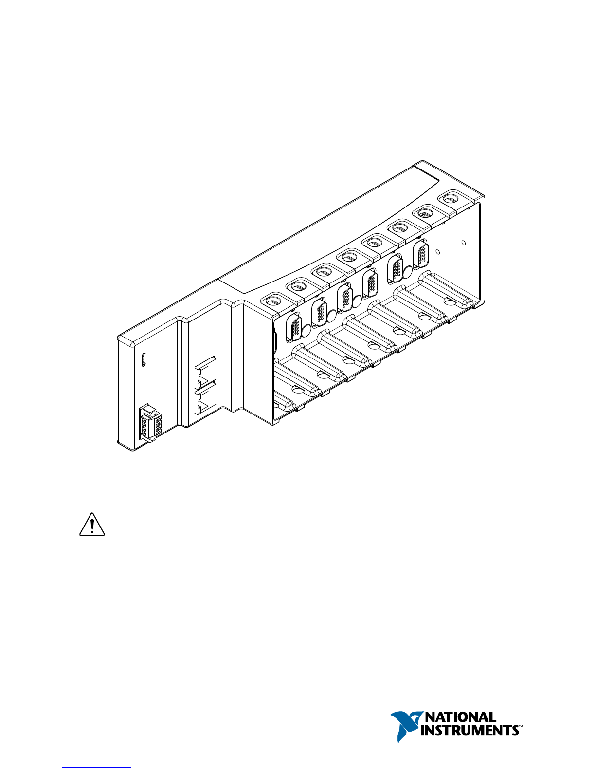
GETTING STARTED GUIDE
NI 9144
Deterministic Ethernet Expansion Chassis for C Series Modules
This document describes how to begin using the NI 9144.
Safety Guidelines
Caution Do not operate the NI 9144 in a manner not specified in this document.
Product misuse can result in a hazard. You can compromise the safety protection
built into the product if the product is damaged in any way. If the product is
damaged, return it to NI for repair.
Safety Guidelines for Hazardous Locations
The NI 9144 is suitable for use in Class I, Division 2, Groups A, B, C, D, T4 hazardous
locations; Class I, Zone 2, AEx nA IIC T4 and Ex nA IIC T4 hazardous locations; and
nonhazardous locations only. Follow these guidelines if you are installing the NI 9144 in a
Page 2
potentially explosive environment. Not following these guidelines may result in serious injury
or death.
Caution Do not disconnect the power supply wires and connectors from the
controller unless power has been switched off.
Caution Do not disconnect I/O-side wires or connectors unless power has been
switched off or the area is known to be nonhazardous.
Caution Do not remove modules unless power has been switched off or the area is
known to be nonhazardous.
Caution Substitution of components may impair suitability for Class I, Division 2.
Caution For Division 2 and Zone 2 applications, install the system in an enclosure
rated to at least IP54 as defined by IEC/EN 60079-15.
Special Conditions for Hazardous Locations Use in Europe and
Internationally
The NI 9144 has been evaluated as Ex nA IIC T4 Gc equipment under DEMKO Certificate
No. 07 ATEX 0626664X and is IECEx UL 14.0089X certified. Each device is marked II
3G and is suitable for use in Zone 2 hazardous locations, in ambient temperatures of -40 °C ≤
Ta ≤ 70 °C.
Caution You must make sure that transient disturbances do not exceed 140% of
the rated voltage.
Caution The system shall only be used in an area of not more than Pollution
Degree 2, as defined in IEC 60664-1.
Caution The system shall be mounted in an ATEX/IECEx-certified enclosure with
a minimum ingress protection rating of at least IP54 as defined in IEC/EN 60079-15.
Caution The enclosure must have a door or cover accessible only by the use of a
tool.
Electromagnetic Compatibility Guidelines
This product was tested and complies with the regulatory requirements and limits for
electromagnetic compatibility (EMC) stated in the product specifications. These requirements
and limits provide reasonable protection against harmful interference when the product is
operated in the intended operational electromagnetic environment.
This product is intended for use in industrial locations. However, harmful interference may
occur in some installations, when the product is connected to a peripheral device or test object,
or if the product is used in residential or commercial areas. To minimize interference with
2 | ni.com | NI 9144 Getting Started Guide
Page 3

radio and television reception and prevent unacceptable performance degradation, install and
use this product in strict accordance with the instructions in the product documentation.
Furthermore, any changes or modifications to the product not expressly approved by National
Instruments could void your authority to operate it under your local regulatory rules.
Caution To ensure the specified EMC performance, operate this product only with
shielded Ethernet cables and accessories.
Caution To ensure the specified EMC performance, do not connect the power
input to a DC mains supply or any supply requiring a connecting cable longer than
3 m (10 ft.). A DC mains supply is a local DC electricity supply network in the
infrastructure of a site or building.
Special Conditions for Marine Applications
Some products are Lloyd’s Register (LR) Type Approved for marine (shipboard) applications.
To verify Lloyd’s Register certification for a product, visit ni.com/certification and search for
the LR certificate, or look for the Lloyd’s Register mark on the product.
Caution In order to meet the EMC requirements for marine applications, install the
product in a shielded enclosure with shielded and/or filtered power and input/output
ports. In addition, take precautions when designing, selecting, and installing
measurement probes and cables to ensure that the desired EMC performance is
attained.
Preparing the Environment
Ensure that the environment in which you are using the NI 9144 meets the following
specifications.
Operating temperature
(IEC 60068-2-1, IEC 60068-2-2)
-40 °C to 70 °C
Operating humidity (IEC 60068-2-56) 10% RH to 90% RH, noncondensing
Pollution Degree 2
Maximum altitude 5,000 m
Indoor use only.
Note Refer to the device specifications on ni.com/manuals for complete
specifications.
NI 9144 Getting Started Guide | © National Instruments | 3
Page 4
Unpacking the Kit
Notice To prevent electrostatic discharge (ESD) from damaging the device, ground
yourself using a grounding strap or by holding a grounded object, such as your
computer chassis.
1. Touch the antistatic package to a metal part of the computer chassis.
2. Remove the device from the package and inspect the device for loose components or any
other sign of damage.
Notice Never touch the exposed pins of connectors.
Note Do not install a device if it appears damaged in any way.
3. Unpack any other items and documentation from the kit.
Store the device in the antistatic package when the device is not in use.
Verifying the Kit Contents
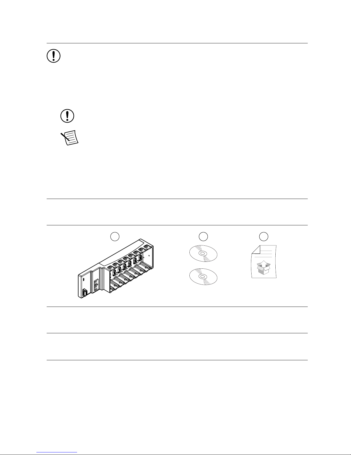
Verify that the following items are included in the NI 9144 kit.
Figure 1. NI 9144 Kit Contents
32
1
1. Chassis with power connector
2. NI Driver Media
3. Getting Started Guide
Installing Software on the Host Computer
When using an NI master controller with the NI 9144, you must install the following
application software and device drivers on the host computer in this order:
1. LabVIEW 2016 or later
2. LabVIEW 2016 Real-Time Module or later
3. NI CompactRIO Device Drivers August 2016 or later
4 | ni.com | NI 9144 Getting Started Guide
Page 5
4. NI-Industrial Communications for EtherCAT 16.1 or later
5. LabVIEW 2016 FPGA Module or later
1
Note For more information about downloading and getting started with EtherCAT
hardware drivers, go to ni.com/info and enter Info Code ecatdriver. NI
recommends that you install the latest version of NI-Industrial Communications for
EtherCAT.
Tip Refer to the user manual on ni.com/manuals for more information about
integrating the NI 9144 with a third-party master controller.
Installing C Series Modules
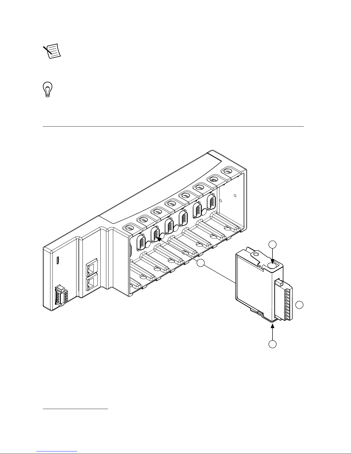
Complete the following steps to install a C Series module.
3
2
2
1
1. Verify that power is not connected to the I/O connector(s) on the C Series module. If the
system is in a nonhazardous location, the NI 9144 can be powered on when you install
modules.
2. Press the latches on the C Series module.
1
Optional installation for FPGA functionalities.
NI 9144 Getting Started Guide | © National Instruments | 5
Page 6
3. Align the C Series module with a slot and seat it in the slot until the latches lock in place.
Removing C Series Modules
Verify that power is not connected to the I/O connector(s) on the C Series module before you
remove a module from the NI 9144. If the system is in a nonhazardous location, the NI 9144
can be powered on when you remove modules.
Connecting the NI 9144
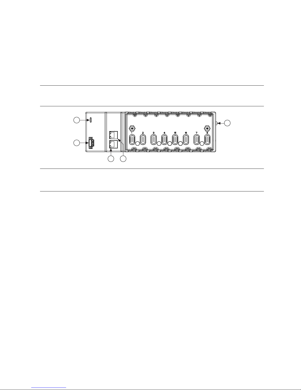
The NI 9144 has the following connectors and LEDs.
Figure 2. NI 9144
2
1
5
3 4
1. LEDs
2. Power Connector
3. OUT Port
4. IN Port
5. Grounding Terminal
Connecting the NI 9144 to Ground
You must connect the NI 9144 grounding terminal to the grounding electrode system of the
facility.
What to Use
• Ring lug
• Wire, 2.0 mm2 (14 AWG) or larger
• Screwdriver, Phillips #2
What to Do
Complete the following steps to ground the NI 9144.
1. Attach the ring lug to the wire.
2. Remove the grounding screw from the grounding terminal on the NI 9144.
3. Attach the ring lug to the grounding terminal.
4. Tighten the grounding screw to 0.5 N · m (4.4 lb · in.) of torque.
5. Attach the other end of the wire to the grounding electrode system of your facility using a
method that is appropriate for your application.
6 | ni.com | NI 9144 Getting Started Guide
Page 7

Caution If you use shielded cabling to connect to a C Series module with a plastic
connector, you must attach the cable shield to the chassis grounding terminal using
2.0 mm2 (14 AWG) or larger wire. Attach a ring lug to the wire and attach the wire
to the chassis grounding terminal. Solder the other end of the wire to the cable
shield. Use shorter wire for better EMC performance.
For more information about ground connections, visit ni.com/info and enter the Info Code
emcground.
Connecting the NI 9144 to Power
The NI 9144 requires a 9 V to 30 V external power supply. The NI 9144 filters and regulates
the supplied power and provides power for the C Series modules. The NI 9144 has one layer
of reverse-voltage protection.
The following table lists the POWER LED indicators.
Table 1. POWER LED Indicators
LED Color LED Pattern Indication
Green Solid The NI 9144 is powered on and the connected power supply is
adequate.
— Off The NI 9144 is powered off.
What to Use
• Screwdriver, 2.54 mm (0.10 in.) flathead
• Power supply, 9 V to 30 V, 20 W minimum
NI recommends the power supply listed in the following table for the NI 9144.
Table 2. NI Power Supplies
Power Supply Part Number
NI PS-15 Industrial Power Supply
(24 VDC, 5 A, 100 VAC to 120 VAC/200 VAC to 240 VAC input)
781093-01
What to Do
Complete the following steps to connect a power supply to the NI 9144.
1. Ensure that your power supply is powered off.
2. Remove the power connector from the NI 9144.
Caution Do not tighten or loosen the terminal screws on the power connector
while the NI 9144 is powered on.
3. Connect the power supply to the power connector, as shown in the following figure.
NI 9144 Getting Started Guide | © National Instruments | 7
Page 8

Figure 3. NI 9144 Power Connections
Power Connector
C
V
Power Supply
+
–
Note The C terminals are internally connected to each other.
4. Tighten the terminal screws on the power connector to 0.20 N · m to 0.25 N · m
(1.8 lb · in. to 2.2 lb · in.) of torque.
5. Install the power connector on the front panel of the NI 9144.
6. Tighten the power connector screw flanges to 0.3 N · m to 0.4 N · m (2.7 lb · in. to
3.5 lb · in.) of torque.
7. Power on the power supply.
Connecting the NI 9144 to an NI Master Controller
Before you connect the NI 9144 to an NI master controller, you must setup and connect the NI
master controller to a network. Refer to your master controller documentation on ni.com/
manuals for setup information.
NI recommends that you install a private network segment for your deterministic Ethernet
expansion devices. Slave devices cause network flooding on a standard network. NonEtherCAT frames jeopardize the system performance and determinism on an EtherCAT
network. Refer to the EtherCAT Technology Group Web site at www.ethercat.org for more
information.
What to Use
• NI 9144
• NI Master Controller
2
• Category 5 Ethernet Cable
Note To prevent data loss and to maintain the integrity of your EtherCAT
installation, do not use a CAT-5 Ethernet cable longer than 100 m. NI
recommends using a CAT-5 or better shielded twisted-pair Ethernet cable
What to Do
Connect the NI 9144 to the NI master controller as shown in the following figure.
2
For supported NI master controllers, visit ni.com/info and enter the Info Code ecatmaster.
8 | ni.com | NI 9144 Getting Started Guide
Page 9
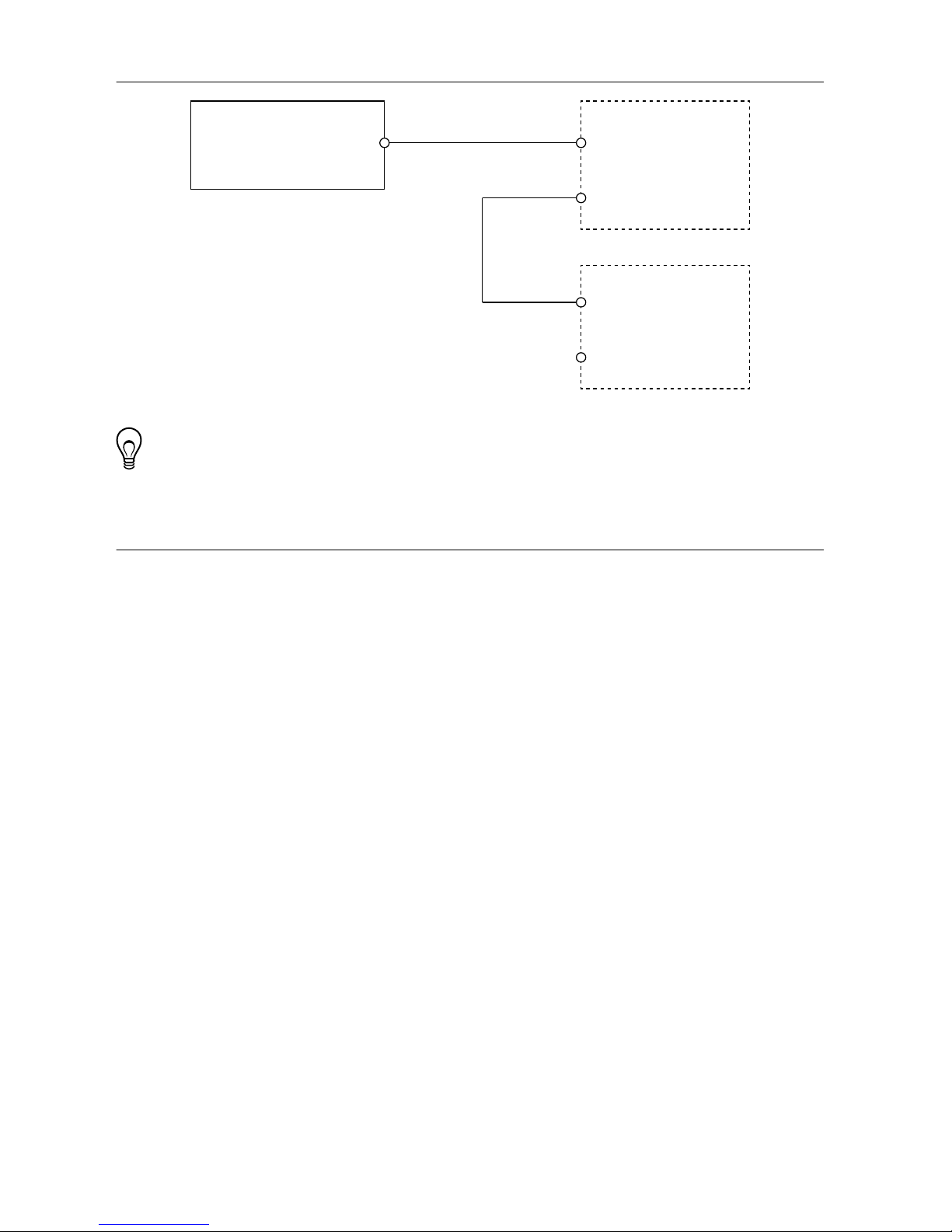
Figure 4. Connecting to an NI Master Controller
NI Master
Controller
Secondary
Ethernet Port
Primary
Ethernet Port
NI 9144
OUT
IN
Host Computer
Ethernet
EtherCat
Tip Use the OUT port on the NI 9144 to connect additional slave chassis.
Third-Party Master Controller
Refer to the EtherCAT® Expansion Chassis Vendor Configurations Guide on ni.com/manuals
for more information about integrating the NI 9144 with a third party master controller.
NI 9144 Getting Started Guide | © National Instruments | 9
Page 10
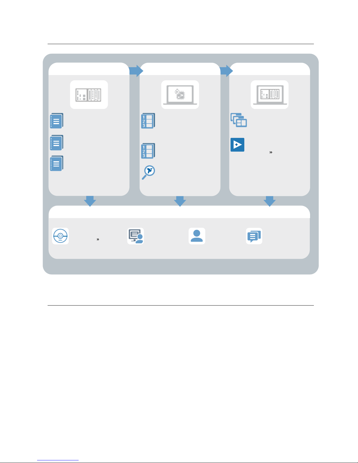
Where to Go Next
APPLICATION
SUPPORT
Services
ni.com/services
NI Community
ni.com/community
NI CompactRIO
Developer’s Guide
ni.com/compactriodevguide
Support
ni.com/support
SOFTWARE
NI 9144 Specifications
ni.com/manuals
NI-Industrial Communications
Getting Started
NI-Industrial Communications
for EtherCAT Help
CompactRIO Sample
Projects
LabVIEW Create Project
HARDWARE
NI 9144 User Manual
ni.com/manuals
C Series Getting
Started Guides
ni.com/manuals
Learn LabVIEW Basics
ni.com/gettingstarted
CompactRIO Examples
NI Example Finder
Software Support
ni.com/info swsupport
Worldwide Support and Services
The NI website is your complete resource for technical support. At ni.com/support, you have
access to everything from troubleshooting and application development self-help resources to
email and phone assistance from NI Application Engineers.
Visit ni.com/services for information about the services NI offers.
Visit ni.com/register to register your NI product. Product registration facilitates technical
support and ensures that you receive important information updates from NI.
NI corporate headquarters is located at 11500 North Mopac Expressway, Austin, Texas,
78759-3504. NI also has offices located around the world. For support in the United States,
create your service request at ni.com/support or dial 1 866 ASK MYNI (275 6964). For
support outside the United States, visit the Worldwide Offices section of ni.com/niglobal to
access the branch office websites, which provide up-to-date contact information.
10 | ni.com | NI 9144 Getting Started Guide
Page 11

Information is subject to change without notice. Refer to the NI Trademarks and Logo Guidelines at ni.com/trademarks for
information on NI trademarks. Other product and company names mentioned herein are trademarks or trade names of their
respective companies. For patents covering NI products/technology, refer to the appropriate location: Help»Patents in your
software, the patents.txt file on your media, or the National Instruments Patent Notice at ni.com/patents. You can find
information about end-user license agreements (EULAs) and third-party legal notices in the readme file for your NI product. Refer
to the Export Compliance Information at ni.com/legal/export-compliance for the NI global trade compliance policy and how
to obtain relevant HTS codes, ECCNs, and other import/export data. NI MAKES NO EXPRESS OR IMPLIED WARRANTIES AS
TO THE ACCURACY OF THE INFORMATION CONTAINED HEREIN AND SHALL NOT BE LIABLE FOR ANY ERRORS. U.S.
Government Customers: The data contained in this manual was developed at private expense and is subject to the applicable
limited rights and restricted data rights as set forth in FAR 52.227-14, DFAR 252.227-7014, and DFAR 252.227-7015.
© 2008—2018 National Instruments. All rights reserved.
372498L-01 November 7, 2018
 Loading...