

Page 1

S310/S320
MODULAR POWER SUBSYSTEM
USER’S MANUAL
Part No. 09-0243
REVISION H
December 16, 2005
Page 2

S310/S320 MODULAR POWER SUBSYSTEM USER’S MANUAL
Document History
Rev A ECO 14813 10/29/1998 B. H.
Rev B ECO 14968 01/19/2000 T. F.
Rev C ECO 15169 01/04/2001 S. H.
Rev D ECO 15185 01/30/2001 J. A.
Rev E ECO 15405 08/19/2001 J. A.
Rev F ECO 15511 05/20/2002 T. F.
Rev G ECO 15572 11/21/2002 J. W.
Rev H ECO 16010 12/16/2005 H. D.
2 of 145
Page 3

S310/S320 MODULAR POWER SUBSYSTEM USER’S MANUAL
Proprietary Rights Notice
This document and the information that it contains are the property of NH
Research, Incorporated. The rights to duplicate or otherwise copy this document,
the rights to disclose the document and its information to others, and the right to use
the information therein may be acquired only by written permission signed by a
duly authorized officer of NH Research, Incorporated.
Unauthorized duplication of software and documentation provided with the test
workstations violates the copyright protection provided by law. However, backup
copies of programs are permitted for archives and recovery from hardware failures.
The material in this publication is current as of the release date on the cover page
and is subject to change without notice. Any questions concerning the product or
any questions or comments concerning this manual should be directed to the NH
Research Field Service Department during normal business hours Monday through
Friday at (949) 474-3900 or FAX (949) 474-7062 or www.nhresearch.com.
POWERTEST and POWERFLEX are trademarks of NH Research, Incorporated.
3 of 145
Page 4

S310/S320 MODULAR POWER SUBSYSTEM USER’S MANUAL
4 of 145
Page 5

S310/S320 MODULAR POWER SUBSYSTEM USER’S MANUAL
TABLE OF CONTENTS
1. GENERAL INFORMATION .............................................................................................................9
1.1 OVERVIEW ....................................................................................................................................9
1.1.1 TOPOLOGY ....................................................................................................................................9
1.2 S300 SYSTEM SPECIFICATIONS ...................................................................................................10
1.2.1 DISCRETE FAULT INDICATOR ......................................................................................................10
1.2.2 REMOTE INTERLOCK ...................................................................................................................10
1.2.3 IEEE-488 CONNECTION ..............................................................................................................10
1.2.4 INPUT POWER ..............................................................................................................................10
1.2.5 INPUT VOLTAGE RANGES - EXTENDED (OPTIONAL) ....................................................................11
1.2.6 SOFT START ................................................................................................................................11
1.2.7 PHYSICAL....................................................................................................................................11
1.2.8 AIRFLOW.....................................................................................................................................11
1.2.9 MODULE REMOVAL.....................................................................................................................11
1.2.10 FRONT PANEL CONTROLS.......................................................................................................11
1.2.11 REAR PANEL CONNECTIONS ...................................................................................................11
1.3 FIRMWARE CAPABILITY ..............................................................................................................12
1.3.1 SELF-TEST AND BUILT-IN-TEST ..................................................................................................12
1.3.2 CLOSED COVER CALIBRATION....................................................................................................12
1.3.3 DISCRETE FAULT INDICATOR ......................................................................................................13
1.3.4 IEEE-488 INTERFACE .................................................................................................................13
1.4 DESIGN AND CONSTRUCTION ......................................................................................................13
1.4.1 RELIABILITY................................................................................................................................13
1.4.2 VIBRATION AND ENVIRONMENTAL .............................................................................................13
1.5 DELIVERABLE DOCUMENTATION ................................................................................................14
1.6 QUALITY PROVISIONS .................................................................................................................14
1.7 APPLICABLE SPECIFICATIONS......................................................................................................14
1.8 OPTIONAL FEATURES ..................................................................................................................15
2. CONTROL CABLING HOOKUP ...................................................................................................17
2.1 INITIAL INSPECTION ....................................................................................................................17
2.2 OPERATING ENVIRONMENT.........................................................................................................17
2.2.1 COOLING SYSTEM .......................................................................................................................17
2.2.2 POWER REQUIREMENTS...............................................................................................................18
2.2.3 RACK MOUNTING........................................................................................................................18
2.3 CABLING HOOKUP.......................................................................................................................18
2.3.1 AC POWER CONNECTIONS ..........................................................................................................18
2.3.2 IEEE-488 CONNECTION ..............................................................................................................19
2.3.3 COM INPUT & OUTUT CONNECTION......................................................................................20
2.3.4 DISCRETE FAULT INTERFACE CONNECTION {DFI} .....................................................................21
2.4 MODULE INSTALLATION AND REMOVAL .....................................................................................25
2.5 MATING CONNECTOR PART DESCRIPTIONS.................................................................................26
2.5.1 CHASSIS DFI CONNECTOR ..........................................................................................................26
2.5.2 CHASSIS COMM IN CONNECTOR...............................................................................................26
2.5.3 CHASSIS COMM OUT CONNECTOR...........................................................................................26
2.5.4 MANUFACTURES DESCRIPTION ...................................................................................................26
3. OPERATING INSTRUCTIONS ......................................................................................................27
3.1 POWER UP SEQUENCE .................................................................................................................27
4. FRONT PANEL PROGRAMMING................................................................................................29
4.1 FRONT PANEL COMPONENTS.......................................................................................................29
4.2 MENU SYSTEM ............................................................................................................................31
5 of 145
Page 6

S310/S320 MODULAR POWER SUBSYSTEM USER’S MANUAL
4.3 MAIN MENU SCREEN ..................................................................................................................31
4.3.1 STATUS BAR................................................................................................................................31
4.3.2 DEVICE INFORMATION ................................................................................................................32
4.3.3 MAIN MENU OPTIONS .................................................................................................................32
4.4 SETUP MENU ...............................................................................................................................33
4.4.1 LOAD SETUP................................................................................................................................33
4.4.2 SOURCE SETUP............................................................................................................................36
4.4.3 CHASSIS CONFIGURATION...........................................................................................................38
4.5 MACRO MENU.............................................................................................................................39
4.5.1 MACRO DISPLAYS.......................................................................................................................40
4.5.2 MACRO OPTIONS.........................................................................................................................40
4.6 MEMORY MENU ..........................................................................................................................41
4.7 UTILITY MENU ............................................................................................................................42
4.8 FRONT PANEL EXAMPLES............................................................................................................43
4.8.1 CALIBRATING A MODULE............................................................................................................43
4.8.2 CREATING A MACRO ..................................................................................................................44
4.8.3 MACRO EXAMPLES......................................................................................................................45
4.8.3.1 BEGIN A MACRO ...............................................................................................................45
4.8.3.2 RECORDING A MACRO ......................................................................................................45
4.8.3.3 ENTERING THE CONTENT OF THE MACRO ........................................................................45
4.8.3.4 COMPLETING THE MACRO ...............................................................................................46
5. IEEE-488 SYSTEM COMMANDS ..................................................................................................47
5.1 S300 SCPI COMMAND INDEX .....................................................................................................47
5.2 S300 SCPI IMPLEMENTATION.....................................................................................................50
5.2.1 SYNTAX NOTATION.....................................................................................................................50
5.3 S300 SCPI LANGUAGE FUNCTIONAL DESCRIPTION ....................................................................52
5.4 MANDATORY COMMANDS...........................................................................................................52
5.5 DEVICE DEPENDENT COMMANDS................................................................................................56
5.6 INSTRUMENT SUBSYSTEM ...........................................................................................................57
5.7 SYSTEM SUBSYSTEM ...................................................................................................................57
5.8 TEST SUBSYSTEM ........................................................................................................................58
5.9 STATUS SUBSYSTEM....................................................................................................................58
5.10 TRIGGER SUBSYSTEM..................................................................................................................59
5.11 DIAGNOSTIC SUBSYSTEM ............................................................................................................61
5.12 DISPLAY SUBSYSTEM ..................................................................................................................64
5.13 SYSTEM PROGRAMMING EXAMPLES ...........................................................................................65
5.13.1 POWER-UP ..............................................................................................................................65
5.13.2 RESET .....................................................................................................................................65
5.13.3 SETTING UP S300 FOR SERVICE REQUEST ..............................................................................65
5.13.4 VIEWING SYSTEM CONFIGURATION .......................................................................................66
5.13.5 MODULE/SYSTEM STATUS......................................................................................................66
5.13.6 ADDING A MODULE ................................................................................................................67
5.13.7 DELETING A MODULE.............................................................................................................68
5.13.8 PARALLELING MODULES ........................................................................................................68
5.13.9 UNPARALLELING MODULES ...................................................................................................69
6. IEEE-488 DC SOURCE COMMANDS ...........................................................................................71
6.1 TEST SUBSYSTEM ........................................................................................................................71
6.2 DIAGNOSTIC SUBSYSTEM ............................................................................................................72
6.3 MEASURE SUBSYSTEM ................................................................................................................74
6.4 CONFIGURE SUBSYSTEM .............................................................................................................75
6.5 FETCH SUBSYSTEM .....................................................................................................................75
6.6 READ SUBSYSTEM.......................................................................................................................76
6.7 CALIBRATE SUBSYSTEM..............................................................................................................77
6.7.1 CAL............................................................................................................................................77
6.7.2 CALIBRATING A DC SOURCE.......................................................................................................77
6 of 145
Page 7

S310/S320 MODULAR POWER SUBSYSTEM USER’S MANUAL
6.8 CURRENT SUBSYSTEM.................................................................................................................79
6.9 VOLTAGE SUBSYSTEM ................................................................................................................82
6.10 OUTPUT SUBSYSTEM ...................................................................................................................85
6.11 SENSE SUBSYSTEM......................................................................................................................85
6.12 DC SOURCE PROGRAMMING EXAMPLES .....................................................................................85
6.12.1 PROGRAMMING MODULE OUTPUT..........................................................................................86
6.12.2 TRIGGER .................................................................................................................................87
7. IEEE-488 LOAD COMMANDS.......................................................................................................89
7.1 TEST SUBSYSTEM ........................................................................................................................89
7.2 DIAGNOSTIC SUBSYSTEM ............................................................................................................89
7.3 MEASURE SUBSYSTEM ................................................................................................................90
7.4 CONFIGURE SUBSYSTEM .............................................................................................................91
7.5 FETCH SUBSYSTEM .....................................................................................................................92
7.6 READ SUBSYSTEM.......................................................................................................................93
7.7 MODE SUBSYSTEM ......................................................................................................................94
7.8 CURRENT SUBSYSTEM.................................................................................................................95
7.9 VOLTAGE SUBSYSTEM ................................................................................................................98
7.10 POWER SUBSYSTEM ..................................................................................................................100
7.11 RESISTANCE SUBSYSTEM ..........................................................................................................101
7.12 LIST SUBSYSTEM.......................................................................................................................101
7.13 LOAD PROGRAMMING EXAMPLES .............................................................................................104
7.13.1 PROGRAMMING LOAD SOFT START ......................................................................................104
7.13.2 TRIGGER ...............................................................................................................................105
7.13.3 PROGRAMMING PULSE MODE...............................................................................................106
8. RESET AND SELF-TEST FUNCTIONAL DESCRIPTION ......................................................107
8.1 S300 RESET OPERATION ..........................................................................................................107
8.2 S300 SELF-TEST OPERATION....................................................................................................107
9. SYSTEM & MODULE ERRORS ..................................................................................................109
9.1 ERROR HANDLING.....................................................................................................................109
9.2 SUPPORTED SCPI ERROR CODES ..............................................................................................110
9.3 S300 SPECIFIC ERROR CODES ...................................................................................................111
10. IEEE488.2 PROGRAMMING EXAMPLE .........................................................................115
10.1 EXAMPLE SYSTEM IEEE SETUP ................................................................................................115
10.2 DC SOURCE OUTPUT SUBROUTINE ...........................................................................................117
10.3 DC SOURCE TRIGGER SUBROUTINE ..........................................................................................119
10.4 LOAD PULSE SUBROUTINE ........................................................................................................121
10.5 LOAD SOFT START SUBROUTINE ...............................................................................................122
10.6 FIND_DEVICE() SUPPORT ROUTINE ............................................................................................125
10.7 GETTYPEDESCRIPTION() SUPPORT ROUTINE .............................................................................125
10.8 INITIALIZATION() SUPPORT ROUTINE .........................................................................................127
10.9 PARSE_DIAG_SYTM() SUPPORT ROUTINE..................................................................................129
10.10 UPDATEFIELDS() SUPPORT ROUTINE .........................................................................................129
10.11 S6K_READ() SUPPORT ROUTINE ................................................................................................132
10.12 S6K_WRITE() SUPPORT ROUTINE ..............................................................................................133
10.13 SERIAL_POLL() SUPPORT ROUTINE............................................................................................133
10.14 SERIAL_POLL_MAV() SUPPORT ROUTINE ................................................................................134
10.15 SERIAL_POLL_OPC() SUPPORT ROUTINE..................................................................................135
10.16 FLUSHS6KERRORS() SUPPORT ROUTINE....................................................................................136
10.17 GET_MODULE_ERROR() SUPPORT ROUTINE..............................................................................137
10.18 ADDIBCNT() SUPPORT ROUTINE ................................................................................................138
10.19 ADDIBERR() SUPPORT ROUTINE.................................................................................................138
10.20 ADDIBSTA() SUPPORT ROUTINE.................................................................................................139
10.21 GPIBERRMSG() SUPPORT ROUTINE ..........................................................................................139
7 of 145
Page 8

S310/S320 MODULAR POWER SUBSYSTEM USER’S MANUAL
11. AVAILABLE OPTIONS .......................................................................................................141
11.1 MODULE TYPES.........................................................................................................................141
11.2 MODULE OPTIONS .....................................................................................................................141
12. SCPI CONFORMANCE INFORMATION.........................................................................143
12.1 SCPI VERSION ..........................................................................................................................143
12.2 SCPI CONFIRMED COMMANDS .................................................................................................143
12.3 SCPI APPROVED COMMANDS ...................................................................................................145
12.4 NON-SCPI COMMAND SYNTAX ................................................................................................145
12.4.1 LOAD MODULE.....................................................................................................................145
8 of 145
Page 9

S310/S320 MODULAR POWER SUBSYSTEM USER’S MANUAL
1. GENERAL INFORMATION
1.1 Overview
The S300 modular design offers a level of flexibility normally associated with custom design
instruments. It has the revolutionary ability to control DC power supplies along with DC
Dynamic loads within the same 5 ¼ chassis. The S300 is ideally suited to support the diversified
requirements of ATE systems.
The S300 DC Modules easily install into one of the six available motherboard slots located in the
S300 Power Subsystem Chassis. A maximum of 2,400 Watts can be delivered per chassis.
The S300 DC Modules are a "Constant Power" design, meaning that the module can deliver
current up to 400w at any point within its operating envelope down to approximately 30% of full
scale voltage. Constant power operation automatically extends the number of output voltage and
current combinations available within the maximum power rating of the module.
The 4100 Series Modular Dynamic Load Modules also use a "Constant Power" design. These
loads use a state-of-the-art thermal management system to achieve a power density of 300W per
slot, for a maximum of 1800W per 5¼ inch S300 chassis. A unique multirange design is used to
cover test requirements from 1.5V to 450V, and current from milliamps to 60A, in five different
output ranges. The power handling capability can be expanded through paralleling additional
modules.
The S300 System consists of a main chassis, which contains six usable slots, a microprocessor
based CPU and front panel keyboard display. Up to six single DC Source or Dynamic Load
Modules may be installed into the chassis. For larger power requirements, up to 64 channels can
be controlled from the main 68000 based CPU. Slave chassis are required providing for a
maximum of 25,600W total continuous DC power output, or 19,200W of Load power
dissipation.
IEEE-488.2 - Native language complies with SCPI Version 1994.0.
MANUAL CONTROL - The instrument can be configured with front panel Keyboard/display.
The majority of all functions that can be performed over the IEEE-488 bus can be performed
manually using the keyboard/display.
1.1.1 Topology
The S300 DC Modules employ switching technology for high operational efficiency and power
density. The filtering used achieves low noise performance comparable to linear converters.
The 4100 Series Loads employ a linear power design for fastest response time and quiet
operation. Constant current, constant power, constant resistance, and constant voltage operating
modes are provided, along with a true hardware SCR and relay crowbar-type short circuit mode.
An advanced Texas Instruments DSP processor is used to tightly synchronize paralleled
modules, as well as provide programmable output waveforms with unprecedented accuracy
compared with older, more limited analog designs.
9 of 145
Page 10
S310/S320 MODULAR POWER SUBSYSTEM USER’S MANUAL
1.2 S300 System Specifications
1.2.1 Discrete Fault Indicator
Each system includes a single rear panel DFI connector in compliance with MATE guidelines.
This generates a contact closure when an error occurs. This may be used in system to control
hardware in the event of an error condition.
1.2.2 Remote Interlock
Each system includes a single rear panel connector for remote TTL output inhibit.
The DFI may be strapped to the interlock line to inhibit output when a fault occurs.
1.2.3 IEEE-488 Connection
A rear panel mounted IEEE-488 connector is provided to support IEEE488-2 remote control.
1.2.4 Input Power
The instrument can be ordered from the factory for either single phase 115 VAC, single phase
230 VAC or three phase 208 VL-L input power operation.
Single Phase Power 115 VAC
Input Voltage Range 103 to 126 VAC
Frequency 47 to 440 Hz
Input Current 30 Amps Max
Maximum Output Power 1,200 Watts per Chassis
Single Phase Power 230 VAC
Input Voltage Range 208 to 264 VAC
Frequency 47 to 440 Hz
Input Current 30 Amps Max
Maximum Output Power 2,400 Watts per Chassis
Three Phase Power 208 VAC L-L
Input Voltage Range 187 to 228 VAC
Frequency 47 to 440 Hz
Input Current 20 Amps per Phase Max
Maximum Output Power 2,400 Watts per Chassis
10 of 145
Page 11

S310/S320 MODULAR POWER SUBSYSTEM USER’S MANUAL
1.2.5 Input Voltage Ranges - Extended (optional)
The instrument can be operated from the foreign power levels with the following deratings:
INPUT
LEVEL MAX OUTPUT POWER
Single Phase 90 VAC to 105 VAC: 1000W
Single Phase 180 VAC to 208 VAC: 2000W
1.2.6 Soft Start
Instrument includes soft start circuitry to limit turn-on surge current.
1.2.7 Physical
Size: 5 ¼ (h) x 19"(w) x 22"(d)
Weight: Master Chassis: <26 lb.
Modules: <6 lb.
Chassis slides: The instrument accommodates CHASSIS TRAK P/N CTHRS-1-18 slides.
1.2.8 Airflow
The cooling fans are located in the front of the S300 chassis. Air is drawn in from ventilation
holes located in the front section of the top, side and bottom panels. The air exits through the
rear panel.
1.2.9 Module Removal
The modules are easily removed/replaced by first uncovering the top cover and then extracting
from the instrument.
1.2.10 Front Panel Controls
The front panel controls consist of a graphical LCD display with accompanying softkeys, cursor
keys, a keypad for numerical input, and an adjust knob to quickly change those numeric values.
This allows for a fully menu driven operation and configuration. Up to six modules may be
monitored simultaneously on the display. All programmable functions can be accomplished via
the front panel keyboard/display.
1.2.11 Rear Panel Connections
All I/O functions are accomplished using rear panel mounted connectors.
11 of 145
Page 12

S310/S320 MODULAR POWER SUBSYSTEM USER’S MANUAL
1.3 Firmware Capability
The S300 firmware contains an extensive command set for control of the instrument over the
IEEE-488 bus interface and via an optional front panel interface. These commands include
instrument settings as a stimulus, and readback instrumentation capability. Additionally,
commands are available for diagnostics, software calibration and configuration/identification
readings. Examples of configuration/identification functions are reading instrument model
number, serial number and firmware version as well as define and/or review logical/physical
settings. Refer to Section 4 for a description of front panel operation. Refer to sections 5, 6, and
7 for a description of SCPI commands.
1.3.1 Self-test and Built-In-Test
The instrument contains advanced on-command and continuous Built-in-test. Two levels of self
diagnostics are supported:
CONTINUOUS BIT
The instruments firmware continuously monitors numerous fault flags. Should any failure or
out-of-tolerance condition result the instrument will automatically alert the host computer and
turn off the output, thus providing protection to the UUT. If the optional isolation relay is
installed the output will be switched to a high impedance state. The fault flags are:
Fault Load DC Source
Over current No Yes
Over voltage Yes Yes
Under Voltage No Yes
Over temperature Yes Yes
SELF-TEST (OPTIONAL)
The self-test assures early detection of hardware problems and minimum time to repair when a
failure does occur. A main status word (1 byte) summarizes the hardware status and firmware
error detection flags. A discrete fault line is also provided. Should more detailed information be
required, status registers provide complete status information on the performance and state of the
hardware. These status words are available via the IEEE-488 bus. All output voltages shall be
isolated from the output terminals via the isolation relay option during testing. If this option is
not installed the set voltage and overvoltage tests are not performed. The test runs in less than 3
minutes and identifies over 90% of all possible faults.
1.3.2 Closed Cover Calibration
Software calibration is provided for the DC Source modules. The DC Source may be fully
calibrated through the IEEE-488 interface bus - no internal adjustments are required.
Load calibration requires a Load Calibrator due to the high accuracy tolerance of the load.
12 of 145
Page 13

S310/S320 MODULAR POWER SUBSYSTEM USER’S MANUAL
Calibration parameters are stored on EEPROM, which resides on each module. Thus, replacing
failed modules does not require recalibration of the instrument.
1.3.3 Discrete Fault Indicator
Each system includes a single rear panel DFI connector in compliance with MATE guidelines.
1.3.4 IEEE-488 Interface
The S300 has a 255 byte wrap around IEEE-488 input buffer. This allows the controlling device
to transmit multiple commands to the S300 before the operation of the first command is
complete. The exception to this is query commands. The S300 has a one message output buffer.
If a second query is executed before the controller retrieves the message from the first query, the
data from the first query is lost.
1.3.5 Background Measurement
The S300 load modules with firmware revisions of 1.04 or greater have the capability measure a
voltage, current, or temperature signal continuously in background. When put in this mode with
the “CONF:BACK” command (see section 7.4) the load module will continuously measure and
store the latest value of the selected signal. The commander of the S300 can retrieve the latest
measurement by issuing the “FETC:BACK?” query command (see section 7.5). The
measurement cycle time of the A/D has not been reduced, but some of the overhead associated
with initiating the measurement has been removed.
To measure transients the MEAS command should be used. The MEAS command will stop the
background measurement and initiate the measurement on the selected signal {e.g. voltage if the
command is MEAS:VOLT?.} A new A/D measurement cycle will start after the command
measurement is complete.
1.4 Design and Construction
The instrument is designed and built to MIL-STD-28800C Type III hardware requirements for
commercial off-the-shelf hardware as well as MIL-STD-45208 quality assurance standards.
1.4.1 Reliability
The fully loaded instrument with six 400W modules installed has a total system MTBF of 15,000
hours as a minimum.
1.4.2 Vibration and Environmental
The S300 meets the following requirements:
Temperature:
Temp (op): -10 to 50 deg C (Max inlet air temperature)
Temp ( non-op): -40 to 85 deg C
Humidity:
95% @ 50 deg C, (Non condensing environments only)
13 of 145
Page 14

S310/S320 MODULAR POWER SUBSYSTEM USER’S MANUAL
Altitude:
Altitude (op): 6,000 ft
Altitude (non-op): 40,000 ft
Vibration:
3 g's in three planes for 15 minutes as follows:
Freq: 10-2000 Hz
Excursion: 0.015 inches
Shock:
15g's on three axis for 11mSec duration using half sinewave shock waveforms.
EMI/RFI:
The instrument is compliant with MIL-STD-461C.
1.5 Deliverable Documentation
NH Research delivers a manual with each instrument:
The User's Manual includes all documentation and procedures to install and interface the
instrument. Included are initial inspection procedures, power and grounding requirements, safety
and hazard warnings, environmental information, operating instructions and remote IEEE-488
software specifications.
1.6 Quality Provisions
NH Research designs and manufactures its instrumentation products to normal commercial
practices and conforms to MIL-I-45208A quality assurance standards and MIL-STD-28800C
performance requirements. Each instrument undergoes 100 hours of elevated temperature burnin testing (50 deg C) prior to final acceptance testing and delivery. Written verification and
performance data are delivered with each unit.
1.7 Applicable Specifications
The instrument complies with the following specifications:
MIL-STD-28800D Type III, Class 3 MIL-STD-45208 Quality Standards
MATE Spec 2806763C VDE Compliant
UL Compliant CSA Compliant
IEC 435 Safety and Isolation IEC 380 Safety Requirements
MIL-STD-461C EMI Part 7 (for commercial test equip.)
14 of 145
Page 15

S310/S320 MODULAR POWER SUBSYSTEM USER’S MANUAL
1.8 Optional Features
The following feature is offered as options on the S300 chassis:
Chassis Slides
400 Hz Operation
The following features are offered as options for a DC module:
Reverse Polarity Relay
Fast Turn On
SCR crowbar Circuit
Isolation Relay (standard on 60v, 80v and 400v)
All load features are included as standard equipment. There are no hardware options.
15 of 145
Page 16

S310/S320 MODULAR POWER SUBSYSTEM USER’S MANUAL
16 of 145
Page 17

S310/S320 MODULAR POWER SUBSYSTEM USER’S MANUAL
2. CONTROL CABLING HOOKUP
2.1 Initial Inspection
The instrument is delivered as follows:
One or more boxes, each containing an S300 chassis.
One box containing miscellaneous accessories and cables.
The miscellaneous accessories and cables include:
Power cord for each S300 chassis.
Auxiliary chassis cables (as required)
Mating connector set
The S300 Power Analyzer User’s Manual
This instrument was carefully tested and inspected for mechanical and electrical defects prior to
shipment. The instrument should be inspected for any visible damage that may have occurred in
transit. If the shipping container is damaged, report any damage immediately to the carrier and
our factory.
2.2 Operating Environment
*****WARNING*****
TO PREVENT POTENTIAL ELECTRICAL OR FIRE HAZARD,
DO NOT EXPOSE EQUIPMENT TO RAIN OR MOISTURE.
TO MINIMIZE SHOCK HAZARD, THE INSTRUMENT AND CABINET
MUST BE CONNECTED TO AN ELECTRICAL GROUND.
In order for the S300 to meet its specifications, the operating environment must be within the
following limits:
Temperature 0 to +50 Degrees C
Relative Humidity < 95% at 50 Degrees C (non-condensing)
2.2.1 Cooling System
The cooling fans are located in the front of the S300 chassis. Air is drawn in from ventilation
holes located in the front section of the top, side and bottom panels. The air exits through the
rear panel. When operating the instrument, provide at least 75mm (3 inches) of clearance at the
rear of the instrument. Failure to allow adequate air circulation will result in excessive internal
temperature, reducing the instrument's safe operating range.
17 of 145
Page 18

S310/S320 MODULAR POWER SUBSYSTEM USER’S MANUAL
2.2.2 Power Requirements
The S300 chassis power connection requires one of the following:
Single phase 115VAC (L-N) +/- 10%, 20A (6 modules, FL) Chassis DC sources limited to
1200W
Single phase 230VAC (L-N) +/- 10%, 20A (6 modules, FL)
Three phase 208VAC (L-L) +/- 10%, 10A/ph. (6 modules, FL)
The instrument is marked by the factory at the POWER INPUT connector on the rear panel. The
marking indicates either a 115VAC or 208/230VAC input level. If 115VAC is indicated, than
the single phase cable provided is used. If 208/230VAC is indicated, than single phase 230VAC
versus 208VAC 3 ph is determined by the cabling being used.
*****WARNING*****
DO NOT CONNECT 230/208VAC SINGLE OR THREE PHASE TO THE S300
IF 115VAC IS INDICATED AT THE POWER INPUT CONNECTOR.
The POWER INPUT setting is selectable by a jumper inside the unit as described in section
2.3.1.
2.2.3 Rack Mounting
The S300 chassis can be rack mounted. Maintenance access and removal is enhanced by adding
the optional rack mounting slide rails.
2.3 Cabling Hookup
***** WARNING *****
LOSS OF LIFE OR SERIOUS INJURY COULD
RESULT FROM UNSAFE OPERATION OF THIS POWER SYSTEM
Remove the instruments from the shipping crates and install the unit in the cabinet. Do the
installation as follows:
Before an S300 may be powered on the chassis cabling setup must be made.
2.3.1 AC Power Connections
*****WARNING*****
TO PREVENT POTENTIAL ELECTRICAL OR FIRE HAZARD,
DO NOT EXPOSE EQUIPMENT TO RAIN OR MOISTURE.
18 of 145
Page 19
S310/S320 MODULAR POWER SUBSYSTEM USER’S MANUAL
*****WARNING*****
LOSS OF LIFE OR SERIOUS INJURY COULD
RESULT FROM UNSAFE OPERATION OF THIS UNIT.
TO MINIMIZE SHOCK HAZARD, THE INSTRUMENT AND CABINET
MUST BE CONNECTED TO EARTH GROUND.
*****WARNING*****
THE GROUND PIN ON THE POWER CORD MUST BE CONNECTED TO EARTH
GROUND DURING OPERATION OF THIS UNIT OR ELSE YOUR LIFE IS IN
DANGER FROM SHOCK OR ELECTRICAL FIRE.
The S300 chassis comes pre-configured to operate from either:
a) 115VAC 1-ph
b) 230VAC 1-ph or 208VAC 3-ph
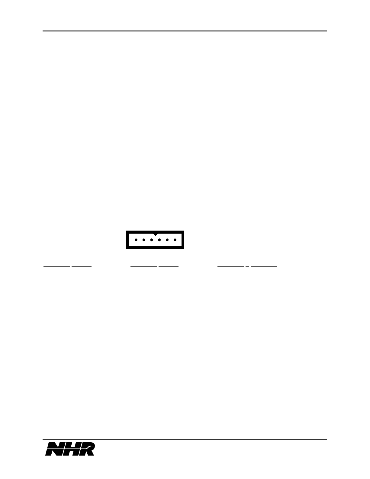
Power is connected to the S300 chassis using the power cord supplied with the unit. The cord
mates to the blue 6 pin male connector located at the bottom of the S300 rear panel and labeled
"INPUT POWER."
1 2 3 4 5 6
115VAC
LINE* 230VAC LINE* 208VAC 3 PHASE*
1. HOT 120VAC 1. HOT 220VAC 1. A PHASE
2. NO CONNECTION 2. NO CONNECTION 2. C PHASE
3. NEUTRAL 120V 3. LOW 220VAC 3. B PHASE
4. NO CONNECTION 4. NO CONNECTION 4. NO CONNECTION
5. CHASSIS GROUND 5. CHASSIS GROUND 5. CHASSIS GROUND
6. CHASSIS GROUND 6. CHASSIS GROUND 6. CHASSIS GROUND
This configuration may be determined by looking at the factory setting that is labeled with a
check mark next to the correct voltage setting.
*The line input may be changed by rewiring the line input connector wiring and moving a cable
connector on the S300 motherboard inside the unit. Move the cable connector to P3 for 115VAC
nominal or P4 for 230VAC/208VAC 3 PH nominal.
2.3.2 IEEE-488 Connection
An IEEE-488 compatible connection is standard on an S300 chassis. To connect to a host
computer attach the IEEE cable to the S320 rear panel connector labeled "GPIB" and to the
appropriate location on the host. The IEEE-488 address must be set in binary using the dip
switch located within the far left side of the S300 rear panel.
19 of 145
Page 20
S310/S320 MODULAR POWER SUBSYSTEM USER’S MANUAL
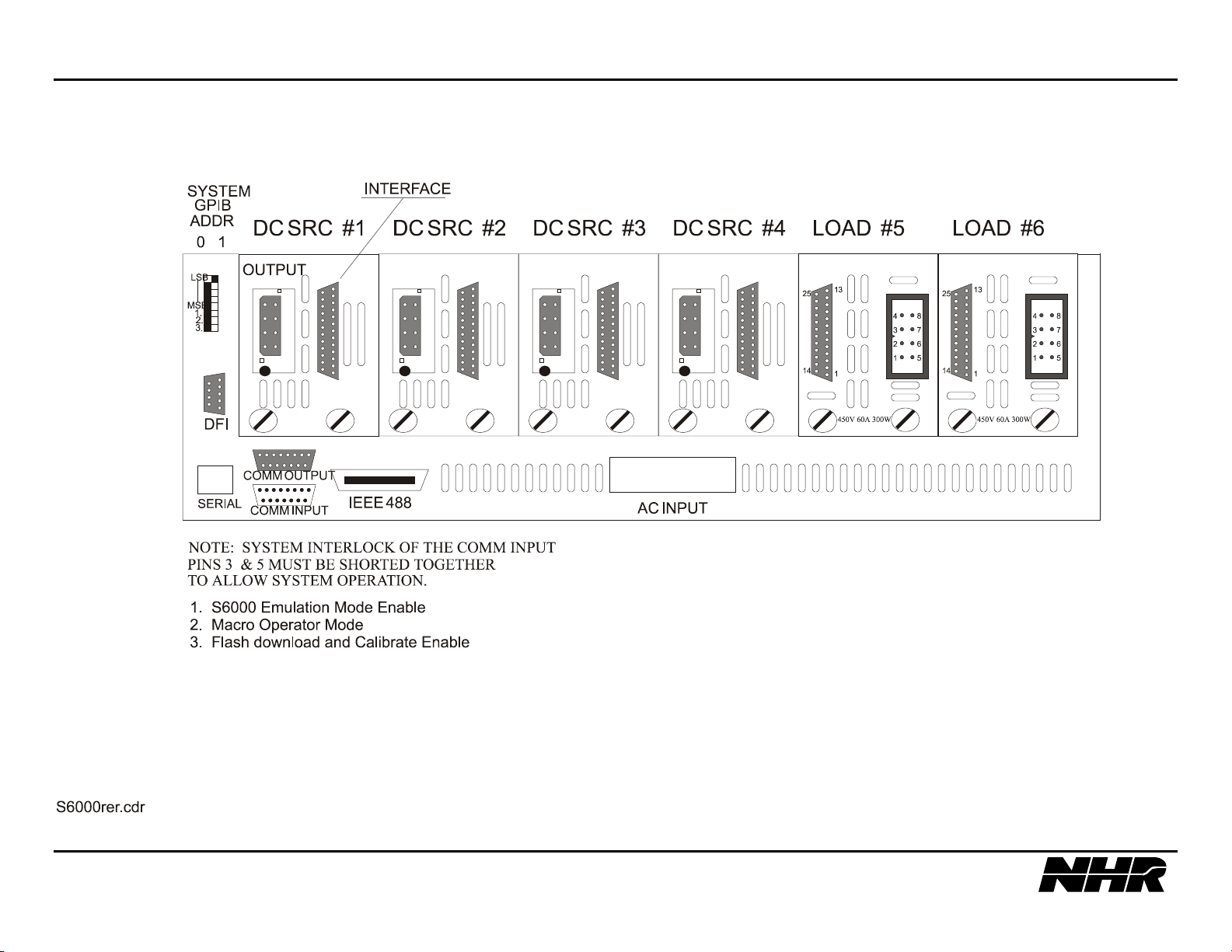
2.3.3 COM INPUT & OUTUT Connection
1. Trigger Connection
The external trigger line is connected to the S300 chassis at the male 15 pin D-sub located on the
lower left corner of the rear panel and is labeled "COMM IN". This is a differential input pair
with 10K ohm pull-up and pull-down. This input must be allowed to maintain greater than +200
mV differential at “TRIGIN+” relative to “TRIGIN-” during normal operation. After the external
trigger circuit is “ARM’d” (see section 5.10 Trigger Subsystem) a minimum 50 msec low pulse
is required to execute the external trigger function. The trigger input must receive a pulse more
negative than -200 mV differential at “TRIGIN+” relative to “TRIGIN-”. This differential
voltage must not exceed ±5 volts or trigger input circuitry will be damaged. The Trigger
input pins are:
pin 2: TRIGIN+
pin 13: TRIGIN-
2. Interlock Connection
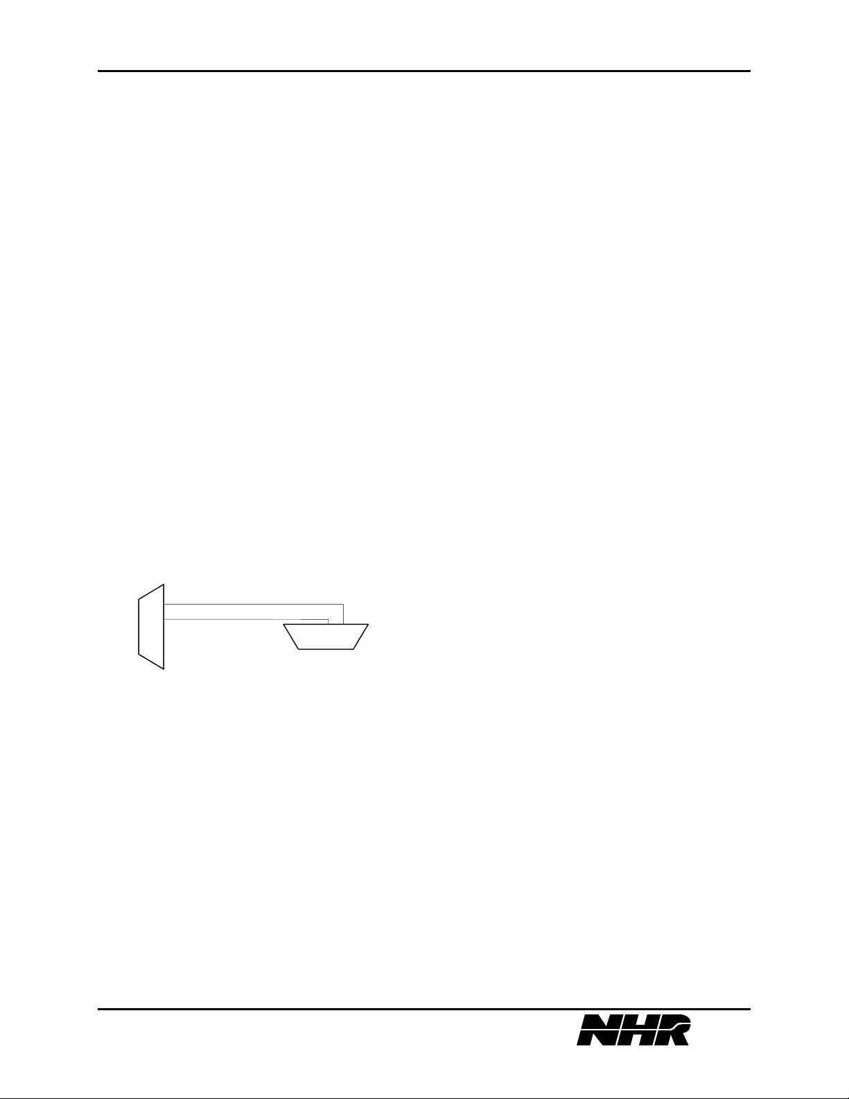
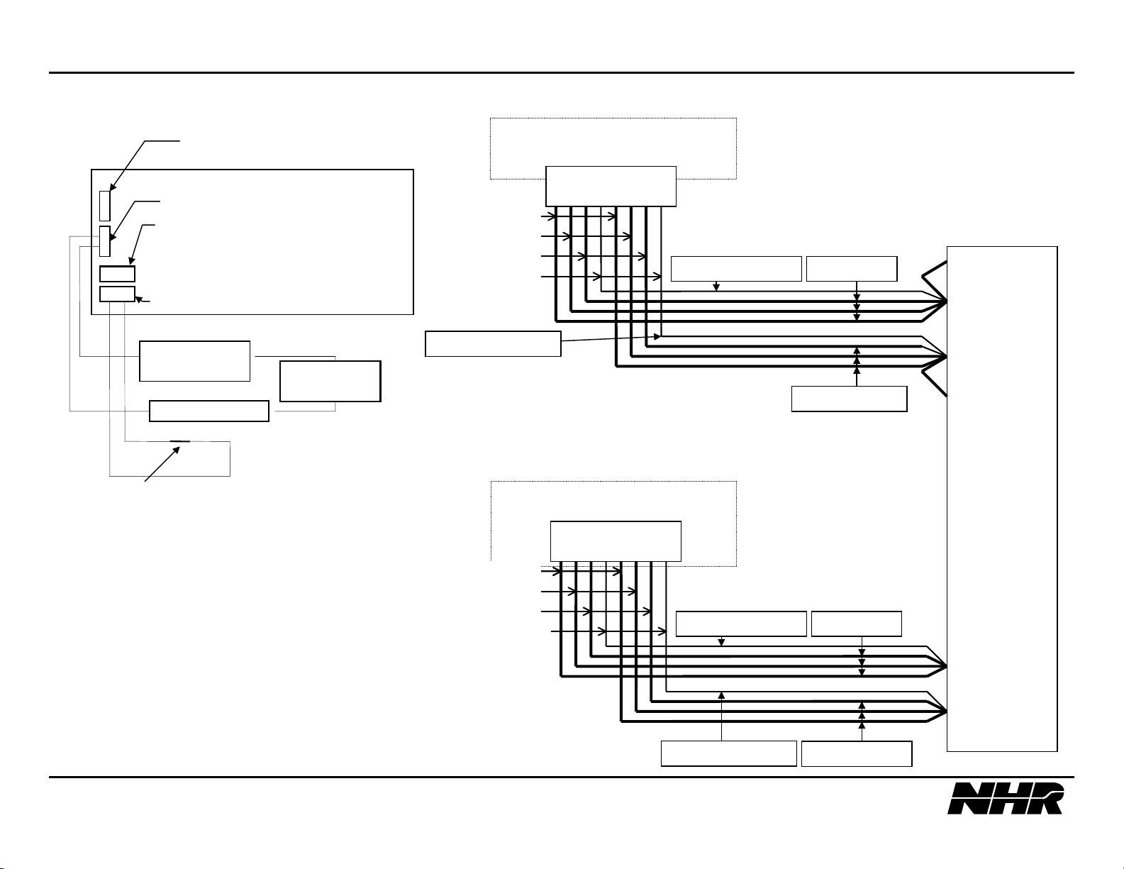
The S300 chassis interlock inhibits module outputs. It is connected at the COMM IN connector.
This signal enables S300 operation by shorting pins 3 and 5. When shipped the S300 has the
connector installed with pins 3 and 5 shorted to avoid any start up problems. The short should be
removed when wiring this interlock into a system.
This interlock could be wired to the DFI that would inhibit all outputs if an error was detected.
The following connection could be made to achieve this:
DFI
5
4
5 3
COMM INPUT
The interlock pins are:
pin 5: INTERLOCK
pin 3: GNDSYS
3. Auxiliary Chassis Connection
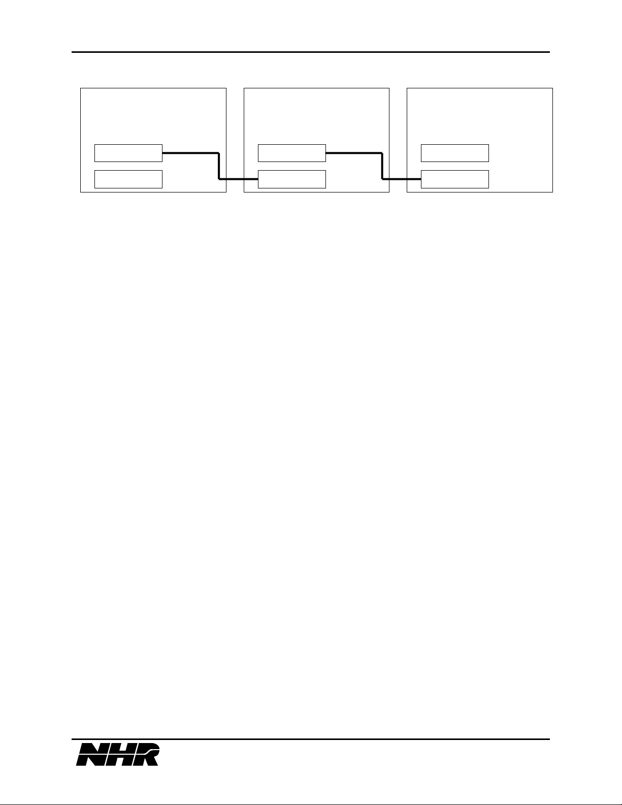
If an auxiliary chassis is being used, a cable is provided to connect the controlling S300 chassis
to the auxiliary chassis. Connection is made from the connector labeled "COMM OUT" on the
controlling chassis to the connector labeled "COMM IN" on the auxiliary chassis.
Additional auxiliary units can be daisy chained from auxiliary chassis #1 to auxiliary chassis #2
and so on in the same fashion.
20 of 145
Page 21
S310/S320 MODULAR POWER SUBSYSTEM USER’S MANUAL
MASTER CHASSIS
SLAVE #1 CHASSIS
COMM OUT
COMM OUT
SLAVE #2 CHASSIS
COMM OUT
COMM IN
COMM IN
COMM IN
2.3.4 Discrete Fault Interface Connection {DFI}
The Discrete Fault Interface connector is a 9 pin female D-sub labeled "DFI" and has the
following pin connections:
pin 4: NORMALLY OPEN DFI RELAY CONTACT
pin 5: COMMON DFI RELAY CONTACT
pin 9: NORMALLY CLOSED DFI RELAY CONTACT
The DFI relay is activated at power up. Therefore under normal operation pins 4 & 5 are shorted
and pins 5 & 9 open. An error will cause the DFI relay to be cleared as per Supported SCPI
Error Codes and 10.3 S300 Specific Error Codes. To set the DFI relay after an error has
occurred you must issue a SYST:ERR? or STAT:QUE? or *RST command. See 5.7 System
Subsystem and Status Subsystem.
21 of 145
Page 22

S310/S320 MODULAR POWER SUBSYSTEM USER’S MANUAL
22 of 145
Page 23
S310/S320 MODULAR POWER SUBSYSTEM USER’S MANUAL
23 of 145
Page 24
S310/S320 MODULAR POWER SUBSYSTEM USER’S MANUAL
N
4
5
3 5
SET IEEE ADDR DIFFERENT
FROM OTHER IEEE DEVICES
S300 CHASSIS
DFI
COMM OUTUT, LEAVE PROVIDED
CONN. ATTACHED IF NO SLAVE
CHASSIS ELSE INSTALL CABLE
PROVIDED W/ SLAVE.
COMM INPUT
TWISTED PAIR
TWISTED PAIR
TWISTED PAIR
TWISTED PAIR
LOAD 450V,60A,300W
OUTPUT CONNECTOR
1 2 3 4 5 6 7 8
+ + + +s − − − −s
VSENSE & VOUT MUST BE
CONNECTED AT THE POWER
SUPPLY OUTPUT TERMINALS
12 GA RED18GA RED/WHT
+VSENSE
+VOUT
TO OTHER
DEVICE’S DFIs
POWER SUPPLY
ORM CLOSED SWITCH
SYSTEM INTERLOCK
SYSTEM DFI
ALARM
WIRE GAUGE IS DEPENDENT ON POWER
18GA BLK/WHT
WIRE GAUGE IS DEPENDENT ON POWER SUPPLY
MAXIMUM OUTPUT CURRENT
3 X 12GA = MAXIMUM 60A LOAD CURRENT.
WIRE VOLTAGE RATING IS DEPENDENT ON
POWER SUPPLY MAXIMUM OUTPUT VOLTAGE.
DC SRC
OUTPUT CONNECTOR
2 3 6 5 4 7 8 1
+ + + +s − − − −s
TWISTED PAIR
TWISTED PAIR
TWISTED PAIR
TWISTED PAIR
12 GA BLACK
12 GA RED18GA RED/WHT
-VOUT
-VSENSE
UNIT
UNDER
TEST
+V IN
SUPPLY MAXIMUM INPUT CURRENT
3 X 12GA = MAXIMUM 60A CURRENT.
-V IN
WIRE VOLTAGE RATING IS DEPENDENT ON
DC SOURCE MAXIMUM OUTPUT VOLTAGE.
18GA BLK/WHT
12 GA BLACK
24 of 145
Page 25
S310/S320 MODULAR POWER SUBSYSTEM USER’S MANUAL
2.4 Module Installation and Removal
Before a module is inserted into the S300 chassis, the MODULE ADDRESS needs to be set.
The address must be a unique number (for a given controller chassis) between hexadecimal 1 and
3F (decimal 1 and 63). This address is programmed into the module using the dip switch. On
DC source modules, this switch is located in the front (air entry end) of the module; on load
modules it is located near the rear of the module, at the bottom edge. To set a binary zero, press
the corresponding switch down, to set a one, leave the switch up.
Each S300 module has two connectors which plug into the motherboard inside the S300 chassis.
Mate modules with the motherboard from the rightmost slot toward the leftmost with respect to
the S300 front panel. If there is a filler panel in that slot, remove it first by unscrewing the two
holding screws. Once the module has been placed firmly into the S300 slot, align and tighten the
thumbscrews located on the rear of the DC module.
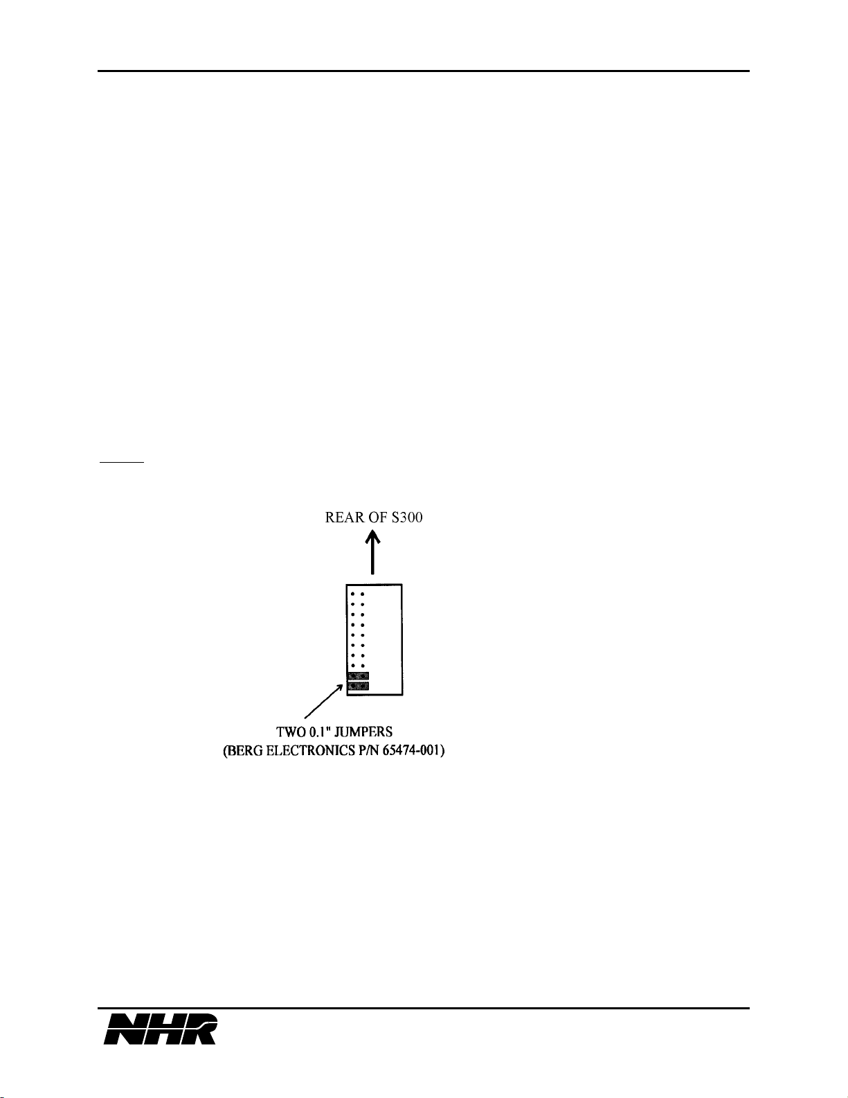
If it is desired to leave a slot blank, two bus continuation connectors must be placed in each slot
that is to be skipped.
NOTE: You must not leave a blank slot between paralleled load modules.
See 5.13.6 Adding a Module and Deleting a Module through IEEE-488 programming.
25 of 145
Page 26
S310/S320 MODULAR POWER SUBSYSTEM USER’S MANUAL
2.5 Mating Connector Part Descriptions
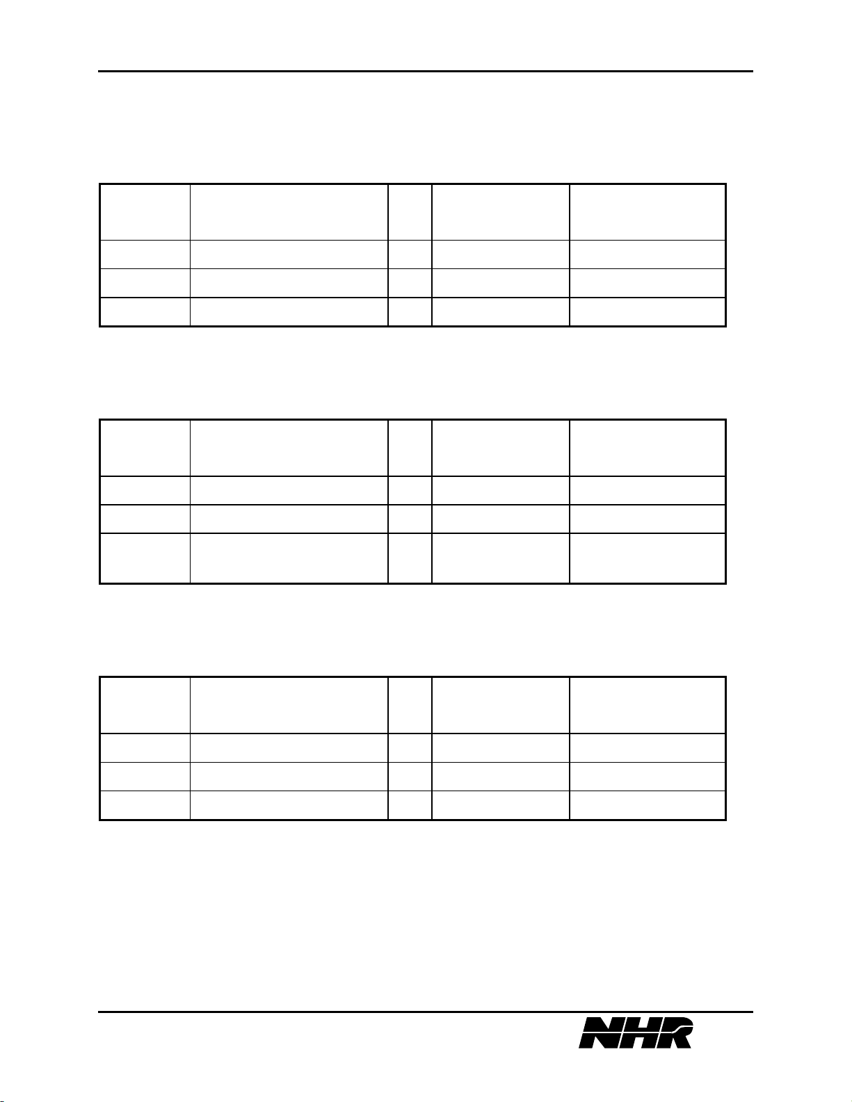
2.5.1 Chassis DFI Connector
N.H. P/N DESCRIPTION QTY COMMERCIAL
MANUFACTURER
PART NUMBER
6202014 DSUB 9PIN SOCKET 1 DE9P ITT CANNON
6201698 DSUB SHELL 1 DE24657 ITT CANNON
6201309 DSUB SCREW LOCK 2 D20419-21 ITT CANNON
2.5.2 Chassis COMM IN Connector
N.H. P/N DESCRIPTION QTY COMMERCIAL
MANUFACTURER
PART NUMBER
6200844 DSUB 15 SOCKET PLUG 1 DA15S ITT CANNON
6200800 DSUB SHELL 1 DA24658 ITT CANNON
6201309 DSUB SCREW LOCK 2 D20419-21 ITT CANNON
2.5.3 Chassis COMM OUT Connector
N.H. P/N DESCRIPTION QTY COMMERCIAL
MANUFACTURER
PART NUMBER
6200799 DSUB 15 PIN SOCKET 1 DA15P ITT CANNON
6200800 DSUB SHELL 1 DA24658 ITT CANNON
6201309 DSUB SCREW LOCK 2 D20419-21 ITT CANNON
2.5.4 Manufactures Description
POSITRONICS INDUSTRIES, INC. CANNON ITT
423 N. CAMPBELL AVE. 10550 TALBERT AVE.
P.O. BOX 8247 P.O. BOX 8040
SPRINGFIELD, MO. 65801 FOUNTAIN VALLEY, CA. 92708
PH# 417-866-2322 FAX# 417-866-4115 PH# 714-964-7400
26 of 145
Page 27

S310/S320 MODULAR POWER SUBSYSTEM USER’S MANUAL
3. OPERATING INSTRUCTIONS
Operation of the S300 requires a proper cabling setup as per Chapter 2. Protection circuits are
available for protection of both the S300 module and the Unit Under Test (UUT). If more power
is required, multiple modules may be used in parallel. These operations are described fully in this
section.
3.1 Power Up Sequence
Turn the front panel power switch to "ON" on each auxiliary chassis first. Next turn on the front
panel power switch of the controller. Observe the green power light and listen for the fans. The
splash screen should be displayed, followed by the main menu.
27 of 145
Page 28

S310/S320 MODULAR POWER SUBSYSTEM USER’S MANUAL
28 of 145
Page 29
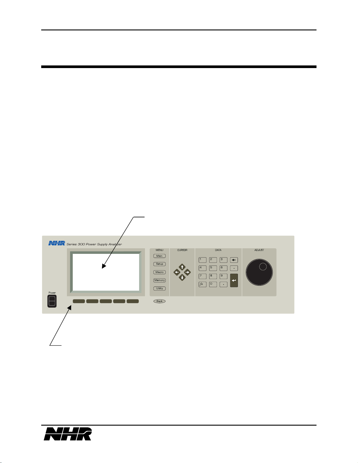
S310/S320 MODULAR POWER SUBSYSTEM USER’S MANUAL
4. FRONT PANEL PROGRAMMING
All system functions are accessed on the S300’s front panel display. The front panel includes the
power switch, a LCD display screen, and various keys designed to make the S300 easy to use
and to operate. The function ability of these various keys are the use of soft keys, menu keys,
cursor keys, a numeric keypad, and an adjust knob are designed to help navigate you through the
S300’s various options as well as being used for all programmable functions.
Up to six modules can be monitored simultaneously on the display screen. This includes
sources, loads, and the S300’s chassis.
This section will describe how to use those functions. The first subsection will describe the use
of the different front panel components; while the following subsections will focus in on the
different capabilities available through the menu system.
Soft Keys
Display Screen
4.1 Front Panel Components
The front panel has seven different components. In order from left to right these components are
the power switch, display screen, softkeys, menu keys, movement keys, numeric data keys, and
the adjust knob.
29 of 145
Page 30

S310/S320 MODULAR POWER SUBSYSTEM USER’S MANUAL
POWER SWITCH - turns on the power to the S300 Power Supply Analyzer. The first screen
to be displayed will be the NH Research splash screen. If no errors are detected in a few seconds
the Main Menu screen will then come up. (If an error is detected the string "INITIALIZING"
will be replaced with "INITIALIZE FAILURE" and a list of power-up error codes, see Section 9
System & Module ERRORs for a description of the error codes. The Enter key must be pressed
to proceed to the Main Menu.)
DISPLAY SCREEN - the display screen gives a status report of all features. This includes
attached devices, their descriptions, volts, amps, and a multitude of options. Often times the fifth
option (located at the bottom right of the display screen) will say “MORE.” The “MORE”
option simply means that there are “more” options than can fit the screen. If “MORE” is
selected another lists of options will appear at the bottom of the screen, or if you have navigated
through all the options already, it will take you back to your previous screen. All functions on
the display screen are controlled by five softkeys located directly below the screen.
SOFTKEYS - the keypad consists of five keys located right below the display screen. These
keys allow you to select any of the five given options located at the bottom of the display screen.
By pressing a key it will activate the corresponding option on the display screen. Soft keys are
context sensitive and change as different menus or devices are selected.
MENU OPTIONS - the menu options allows you to control and configure all the key features of
the S300. The Menu choices are Main, Setup, Macro, Memory, Utility, and Back (to the
previous screen). These options will be fully described in Section 4.2 through Section 4.7.
CURSOR - cursor movement on the display screen is controlled with right, left, up and down
arrows. The cursor will auto-repeat its movement if you hold a given arrow key down
Function (fn): the function key allows you to scroll quickly through a list of items or to activate
alternate key functions. To utilize the function key first press the fn key and then use the up or
down cursor arrow to direct which way in the given list you want to travel.
DATA (numeric keypad) - the numeric keypad is numbered 0 through 9 and also contains a
decimal, minus sign, backspace, enter, and function (fn) keys.
0 through 9 numerical keys: are used to input numeric data.
backspace: allows you to delete the last character inputted. If the key is held down it will delete
character spaces until released.
Minus Sign (-): allows you to input negative numbers.
Enter: the ‘Enter’ key is used to enter accepted data and menu options input with the numerical
keys. If no menu selection is inputted and the ‘Enter’ key is pressed, the menu tree will be
traversed up one level. However, if you are located on the main menu the ‘Enter’ key will select
the setup menu only.
Decimal (.): allows you to input numerical data below whole numbers.
ADJUST KNOB - the adjust knob is used to quickly adjust an inputted numeric value. If you
turn the knob to the right the numeric value will go higher, while if you turn it to the left the
numbers will go lower. The adjust knob can also be used as an ‘Enter’ key. To utilize this
function just press in the knob and your value will be accepted.
30 of 145
Page 31
S310/S320 MODULAR POWER SUBSYSTEM USER’S MANUAL
4.2 Menu System
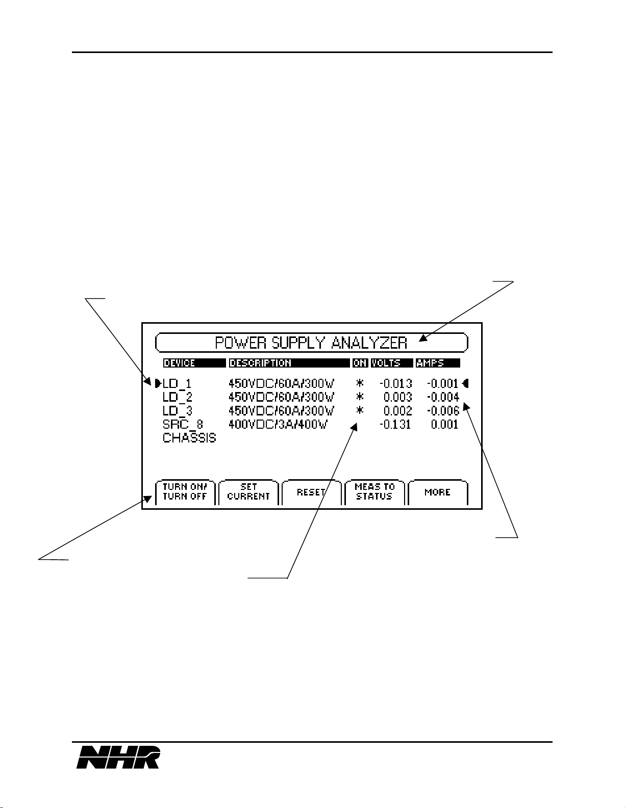
The S300’s Menu System will be described in the following subsections. Each subsection will
show a picture of the screen and then describe its contents.
4.3 Main Menu Screen
After the Power-On Self-test (POST) the Main Menu screen will be displayed. This self-test
checks for different possible power-up errors. If such an error occurs check Section 9 for a
description of the error code. The Main Menu screen displays a Status Bar at the top of the
screen, information about all connected devices in the center of the screen and device specific
options at the bottom of the screen.
Status Bar
Devices
Selection Marker
Options
Device State Annunciator
4.3.1 Status Bar
The Status Bar is located at the top of the Main Menu screen. This bar can display the voltage
and current measurements of up to two selected devices at once. Upon power-up the Status Bar
will say “Power Supply Analyzer.” To switch to measurement display select your chosen
device(s) with the cursor and then select the Meas(urement) to Status option . If no
measurements are displayed the main title will be left in its place.
31 of 145
Page 32

S310/S320 MODULAR POWER SUBSYSTEM USER’S MANUAL
4.3.2 Device Information
Current information about different connected modules as well as the analyzer’s chassis is
located in the middle of the Main Menu screen. The information displayed will be connected
devices, device description, voltage, and amps.
DEVICE - the device heading will display whether a given module is considered a Source
(SRC), a Load (LD) or the S300’s Chassis. Also for example, if you have two different source
modules by default they will be numbered as SRC_1 and SCR_2. However, you can change the
names to whatever you like. If you have more than six connected devices you can scroll through
your list using the cursor keys located in the middle of the front panel.
DESCRIPTION - the description of the given devices will display its voltage, whether it is an
AC and/or DC source, and its maximum amps as well as wattage.
DEVICE STATE ANNUNCIATOR – if there is an error associated with a given device or the
chassis an “E” will appear under the ON column. An asterisk (*) will appear if the device is ON
and there will be a blank space if the device is OFF. For further details See Section 9 System
and Module Errors.
VOLTS - displays the voltage measurement of a given device.
AMPS - displays the amp measurement of a given device.
SELECTION MARKERS – a selection marker is displayed by an arrow that points at the
current selected device or option.
4.3.3 Main Menu Options
The Main Menu options are the five outlined buttons located on the bottom of the display screen.
These buttons are activated by the keys located right underneath the display screen. These
options are as follows:
TURN ON/OFF - allows you to turn on and off the selected device.
SET VOLTAGE - allows you to set the voltage for the currently selected device. This will take
you to a screen where you can input the desired voltage with either the data keys or the adjust
knob.
RESET - resets the selected device.
MEASUREMENT TO STATUS - the current volts and amps measurement of the selected
device in the Status Bar that is placed at the top of the display screen. With this option only two
devices can be placed on the Status Bar at once.
CLEAR STATUS - allows you to clear the device measurements in the Status Bar. (Displayed
after pressing the “MORE” option.)
TOGGLE STATUS - allows you to toggle between the device measurements and menu title
mode. (Displayed after pressing the “MORE” option.)
VIEW ERROR LOG – displays the most recent logged error for the selected device. See
Section 9 System and Module Errors for further details.
32 of 145
Page 33
S310/S320 MODULAR POWER SUBSYSTEM USER’S MANUAL
4.4 Setup Menu
4.4.1 Load Setup
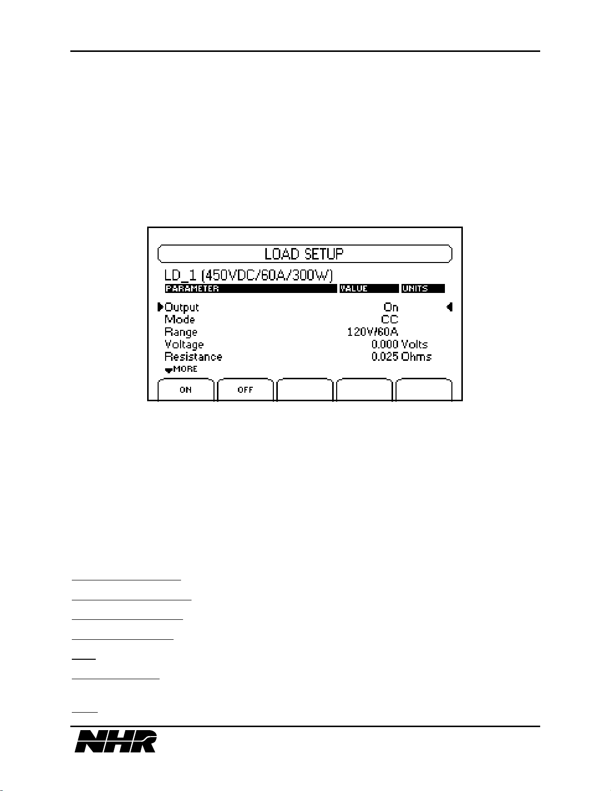
The Load Setup Menu is the load specific Setup Menu. This menu can be reached by selecting a
load device from the Main Menu and then pressing SETUP. The Load Setup Menu allows you
to change the value of every load module parameter. These different parameters are as follows:
1. OUTPUT - allows you to toggle the module’s ON/OFF state as well as the state of its
isolation relay if installed.
The default/reset value of this parameter is the ON state.
2. MODE - Allows you to change the mode of a stand alone or master load module. Refer to
S300 Hardware Reference Manual 09-0257 Section 1.4.3 for a description of the load modules
operating mode. These different modes are as follows:
Constant Current (CC) - sets the load into Constant Current Mode.
Constant Resistance (CR) - sets the load into Constant Resistance.
Constant Voltage (CV) - sets the load into Constant Voltage.
Constant Power (CP) - sets the load into Constant Power.
Auto - sets the load into Auto Mode.
Short Circuit (SC) - sets the load into Short Circuit Mode. Selecting any other mode after short
circuit has been programmed will transition the load out of Short Circuit Mode.
Pulse - sets the load into Pulse mode.
33 of 145
Page 34

S310/S320 MODULAR POWER SUBSYSTEM USER’S MANUAL
3. RANGE - allows you to set the load working voltage and current range. Default/reset value
is 120v/60a, 80v/60a.
4. VOLTAGE
Default/reset value is 0 volts.
5. RESISTANCE
The unit must be in Constant Resistance Mode when setting. Current must first be programmed.
Calculate the current by dividing (Max. Voltage)/(Desired Resistance). Enter this calculated
current. Next enter the desired Resistance. Keep in mind that the Max. Voltage must be equal to
or less than the maximum voltage for the range.
The default/reset value for this parameter is 1 ohm. The minimum input value is based upon the
present operating range and the voltage parameter; see Section 1.4.3 of the S300 Hardware
Reference Manual 09-0257 for a table of resistance to range values. The maximum input value is
the maximum resistance level for the present range setting.
6. CURRENT - allows you to set the current parameter. You will be prompted to change the
value to a new current level. In Constant Resistance operation current must be entered before
resistance. In Constant Resistance Mode program current changes do not take effect until the
resistance is entered.
The default/reset value of this parameter is 0 amps. The maximum input value is the maximum
current for the module type as is specified in Section 11.1 under Module Types.
- allows you to set the voltage level for constant voltage mode operation.
- sets the resistance level for the Constant Resistance Mode (CR) in ohms.
7. POWER - allows you to set the power level for constant power mode or auto mode.
Default/reset value is 0 watts.
8. RISE TIME - the rise time parameter programs, in seconds, the time to transition the current
from the present level to a higher level.
The default/reset value for this parameter is 10 µsec. The minimum input value is 10 µsec. The
maximum input value is 8.0 seconds. The resolution is 2 µsec.
9. FALL TIME - the fall time parameter programs, in seconds, the time to transition the current
from the present level to a lower level.
The default/reset value for this parameter is 10 µsec. The minimum input value is 10 µsec. The
maximum input value is 8.0 seconds. The resolution is 2 µsec.
NOTE: For further details on Pulse Mode Operation see Section 1.4.4 of the S300 Hardware
Reference Manual 09-0257.
34 of 145
Page 35
S310/S320 MODULAR POWER SUBSYSTEM USER’S MANUAL
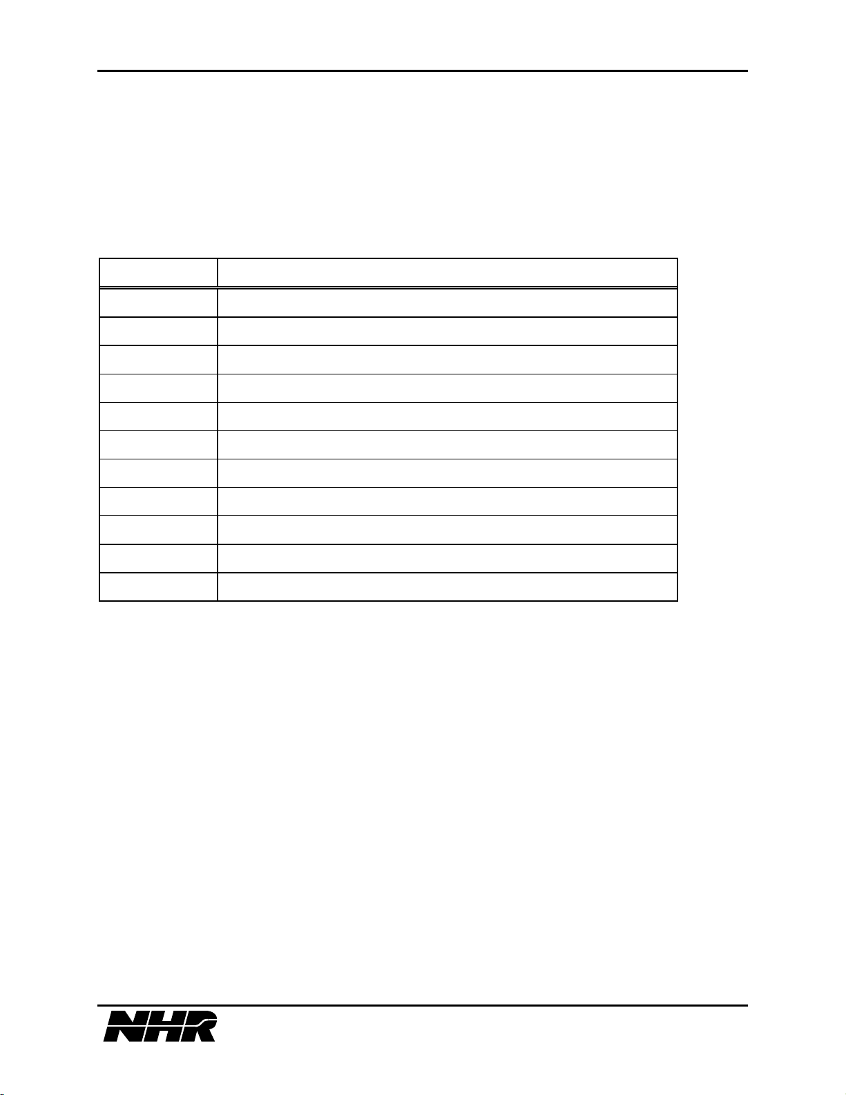
10. PULSE ORDER - specifies the sequenced order of states for Pulse Mode operation. 1, 2,
and 3 are pulse states and 0 causes Pulse Mode operation to halt. Pulse Mode always starts from
state 3, the nominal amps, and transitions to state 1. Select the soft key corresponding to the
desired sequence.
Below are listed the legal pulse sequences.
Sequence Description
1,0 Current step from nominal
1,2,0 Single shot two level pulse - nominal goes to state #2 amps
1,3,0 Single shot two level pulse - nominal is unaffected
1,2,3,0 Single shot three level pulse - nominal unaffected
1,3,2,0 Single shot three level pulse - nominal goes to state #2 amps
1,2,1 Continuous two level pulse
1,3,1 Continuous two level pulse
1,2,3,1 Continuous three level pulse
1,3,2,1 Continuous three level pulse
1,2,3,2 Continuous two level pulse with starting transient
1,3,2,3 Continuous two level pulse with starting transient
For single shot pulses the nominal current level will updated to the final state of the pulse
sequence. When continuous Pulse Mode operation is halted the current level returns to nominal.
11. PULSE 1 AMPLITUDE - sets the current level for Pulse Mode State 1.
The default/reset value for this parameter is 0 amps. The minimum input value is 0 amps. The
maximum input value is the maximum current level for the present range setting.
12. PULSE 2 AMPLITUDE - sets the current level for Pulse Mode State 2.
The default/reset value for this parameter is 0 amps. The minimum input value is 0 amps. The
maximum input value is the maximum current level for the present range setting.
13. PULSE DWELL 1 - sets the dwell time, in seconds, for the Pulse Mode State 1.
The default/reset value for this parameter is 1 msec. The minimum input value is 20 µsec. The
maximum input value is 8.0 seconds. The resolution is 2 µsec.
35 of 145
Page 36
S310/S320 MODULAR POWER SUBSYSTEM USER’S MANUAL
14. PULSE DWELL 2 - dwell time for Pulse Mode State 2.
The data range is the same as Pulse Mode State 1.
15. PULSE DWELL 3 - dwell time for Pulse Mode State 3.
The data range is the same as Pulse Mode State 1.
16. MODULATION STATE
: Default Off - allows you to set the power level for constant
power mode or auto mode. Default/reset value is “OFF”.
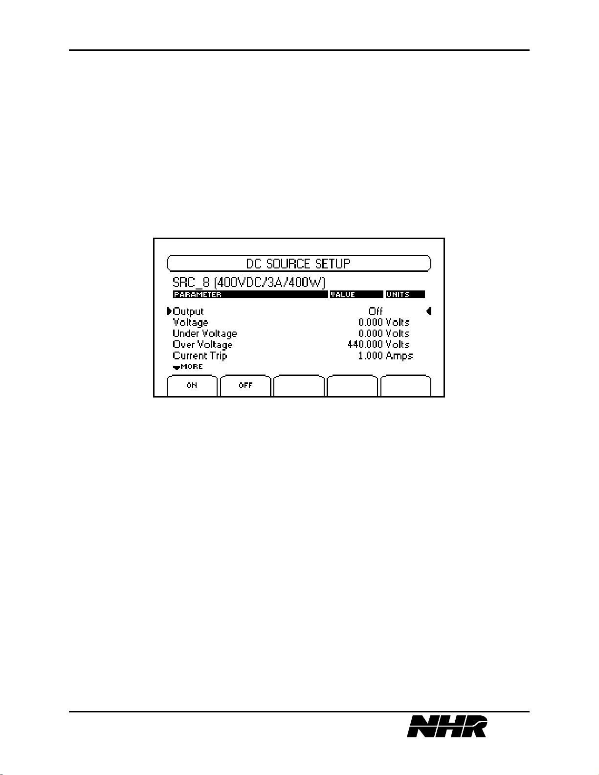
4.4.2 Source Setup
The Source Setup Menu allows parameter viewing and modification for a stand alone or master
DC Source module. To access the Source Setup Menu, first move the cursor to your desired
source and input your selection with the Enter key or press SETUP.
Module parameter values and states are programmed by selecting the appropriate menu option
and entering any required data when prompted. When the menu parameters are programmed the
displayed values are updated to the programmed values.
The following options are available from the Source Setup Menu:
1. OUTPUT - toggles the module ON/OFF state as well as the state of its isolation relay if
installed.
The default/reset value of this option is the OFF state.
Before setting up a voltage and turning on the output the protection options should be
setup. During the setup of these options, limit the module to work in a specific range in
order to prevent damage to the UUT.
36 of 145
Page 37

S310/S320 MODULAR POWER SUBSYSTEM USER’S MANUAL
2. VOLTAGE - sets the output voltage parameter in volts. You will be prompted to input the
new voltage level.
The default/reset value of this parameter is 0 volts. See Section 11.1 Module Types for further
details. The maximum input value is the maximum voltage for the module type as specified in
Module Types. The minimum input value is 0 volts, unless the module includes the reverse
polarity option. If the module includes the reverse polarity option the minimum input voltage is
the negative of the maximum voltage.
3. UNDER VOLTAGE - sets under voltage error level, in volts. If the module detects an
absolute voltage level less then the under voltage trip parameter it will shutdown and generate an
Module Voltage Error. To disable under voltage checking enter the value 0 when prompted for
the under voltage parameter. This parameter should be disabled while the output is off.
The default/reset value of this parameter is 0 volts in the OFF state. The maximum input value is
the maximum voltage for the module type as specified in Module Types. The minimum input
value is 0 volts. For modules, which include the reverse polarity option, this parameter is an
absolute value.
4. OVER VOLTAGE - sets the over voltage trip parameter, in volts. If the module detects an
absolute voltage level greater then the over voltage trip parameter it will shutdown and generate
a Module Voltage Error. To toggle over voltage checking between on and off, enter the value -1
when prompted for the overvoltage parameter.
The default/reset value of this parameter is 110% of the maximum voltage for the module type as
specified in Module Types. The maximum input value is 110% of the maximum voltage. The
minimum input value is 0 volts. For modules, which include the reverse polarity option, this
parameter is an absolute value.
5. CURRENT TRIP - sets current trip parameter, in amps. If the module detects a current
output greater then the current trip parameter the S300 will shutdown and generate a Module
Current Error.
The default/reset value of this parameter is 110% of maximum current for the module type as
specified in Module Types. The maximum input value may be slightly higher or lower than
110% depending on which type of module you have loaded. The minimum input value is 0 amps.
6. TRIP DELAY - sets the time delay, in milliseconds, before a current trip will generate a
Module Current Error.
The default/reset value of this parameter is 65.535 seconds. The maximum input value is
dependent to which type of module you currently have loaded, but it will usually be around the
default setting of 65.535 seconds. The minimum input value is 0.001 seconds.
7. CURRENT LIMIT - sets the current limit parameter in amps. You will be prompted to input
the new current limit level.
37 of 145
Page 38
S310/S320 MODULAR POWER SUBSYSTEM USER’S MANUAL
The default/reset value of this parameter is the modules maximum power divided by its
maximum voltage, in amps. The maximum input value is the maximum current for the module
type as specified in Module Types. The minimum input value is 0 amps.
8. SENSE STATE - sets the sense relay state between local and remote.
The default/reset value of this parameter is local.
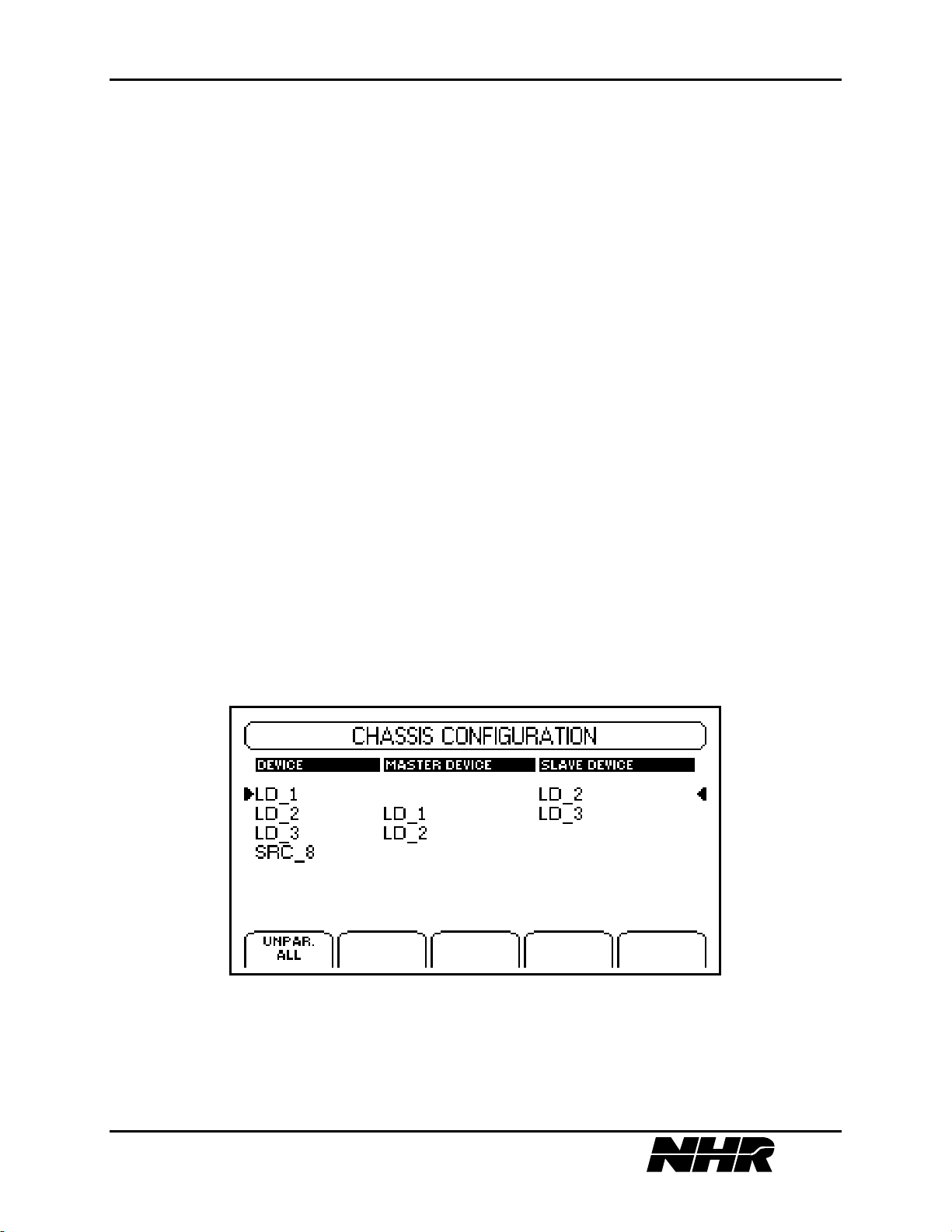
4.4.3 Chassis Configuration
This submenu allows you to modify the S300’s chassis configuration. To reach this option,
select the chassis device from the Main Menu and then press SETUP.
The user may parallel modules to create a master module, which has increased module limits for
power handling. To parallel a group of modules the configuration menu is selected by selecting
the chassis device and selecting SETUP menu. Only modules of the same type may be
paralleled together. When modules are paralleled only the resulting master module will appear
on the instrument device menus until the modules are unparalleled.
The S300 chassis has several restrictions on paralleling modules, which are enforced by the
menu logic. Only like modules will appear on the Slave Select menu and only modules, which
are down, stream in the communication bus will appear. For more information on Paralleling
modules refer to Section 2.5 Parallel Modules Connections.
The options that are available through the S300’s chassis configuration are as follows:
PARALLEL MODULE - to parallel a group of modules the configuration of the master device
must be modified first. The slave modules are added in sequence after the master. Only
38 of 145
Page 39

S310/S320 MODULAR POWER SUBSYSTEM USER’S MANUAL
modules of the same type may be paralleled together. For example, sources can only be
paralleled with other like sources and loads with other like loads.
When modules are paralleled only then can the master device be programmed. Commands, other
then unparalleling, sent to the slave device cause an unknown module error to be added to the
modules error queue. See Section 2.5 for further details.
UNPARALLEL MODULE - to unparallel a group of modules the configuration of the last
slave device must be modified first. The modules will be removed from the group in sequence
up to the master module. See Section 2.5 for further details.
UNPARALLEL ALL - this softkey will remove all virtual modules created as well as returning
all modules to stand alone operation.
SELECT SLAVE – this option appears only during the process of paralleling modules. It will
display a list of possible slave devices of which you have the option to SELECT or to EXIT to
the previous screen.
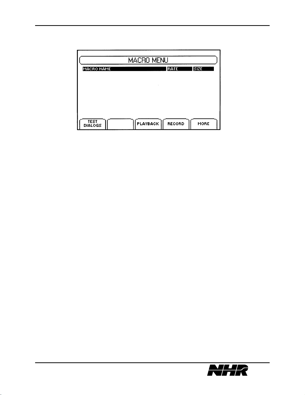
4.5 Macro Menu
The Macro Menu allows you to record and playback sequential sequences of instrument
operation and tests. Once you create the macros you can store these subroutines and
multifaceted tests into nonvolatile memory. There is available memory storage of up to 128
macros using a maximum of 1 megabyte of memory.
The Macro Menu shows the stored macros available for playback. Select the desired macro and
select the playback softkey. All user keystrokes and interaction with modules are played back
sequentially. Wait for the playback to complete or if necessary select the abort softkey while
playback is in progress to stop the macro playback prematurely.
NOTE: if macro playback is aborted the instrument state is unknown. Turn off modules and/or
reset modules as necessary to restore the instrument to a known state.
39 of 145
Page 40
S310/S320 MODULAR POWER SUBSYSTEM USER’S MANUAL
4.5.1 Macro Displays
The different options you can perform or monitor with the Macro Menu are as follows:
MACRO NAME - allows you to name your newly created macro or rename an existing one.
You can use a maximum of 25 character spaces for your name.
RATE - allows you to toggle between normal and fast rates.
SIZE - displays the amount of memory in bytes that your particular macro requires.
4.5.2 Macro Options
TEST DIALOGS - allows for two types of tests. The two types of tests are Voltage Tests and
Current Tests. Both tests display a pass/fail dialog as well as allowing you to input minimum
and maximum ranges to be tested. If a macro is recording the test placed into the sequence of
macro events and will test the measured parameter when the macro is played.
PLAYBACK - allows you to playback a chosen macro. It does not matter if the macro is just
one quick simple test or is an overall test comprised of a multitude submacro routines, either way
each aspect will be played back to you.
RECORD - the Record Option allows you to create a macro and save it into memory. The
macro can be one routine or a whole series of routines. There is no limit to how many
subroutines you can incorporate into a macro. Your macro will also be saved at the same rate
and have the same parameters you recorded it at. However, you can increase the rate of your
macro’s playback with the Toggle Rate Option. For instruction on how to create a macro See
Section 4.8.2
STOP RECORDING - the Stop Recording Option will only appear once you are actually
recording a macro. Once you have completed recording your macro, select this option and your
macro will be complete. From there, displays will then come up for you to save your macro and
then to name it.
40 of 145
Page 41

S310/S320 MODULAR POWER SUBSYSTEM USER’S MANUAL
TOGGLE RATE - allows you to toggle the time rate of a given macro between normal and fast.
The normal time rate indicates the same timing at which the macro was recorded, while the fast
rate will have your macro playback at the fastest speed possible.
DELETE - allows you to delete a macro that you want to discard. Simply select the macro you
want to delete and then a display screen will come up to ask if you are sure. If you are you sure
you want to delete the selected macro choose ACCEPT VALUE and if you made an error select
CANCEL. Once you accept to delete a macro you will be unable to retrieve it.
4.6 Memory Menu
The Memory Menu is activated by selecting the Memory button located under the MENU
column on the front panel of the S300.
The instrument state includes all module parameter settings for each installed module. This
allows a quick method to setup the instrument in a predetermined configuration. When saving
the instrument records all information regarding the chassis setup, and installed modules to a
memory restore file that is given a descriptive name and then appears in the memory menu list.
When restoring an instrument state, the appropriate restore file is selected and the RECALL
softkey will restore the instrument state. The instrument will consistently restore the chassis
configuration first then load modules in increasing address order and then source module in
increasing address order. Caution is advised as restoring an instrument state may change source
voltages and turn on outputs that were previously off.
The options for the Memory Menu are as follows:
RECALL STATE - displays a directory of the different macros stored in the chassis. There is
enough storage area to hold up to 128 different macros.
SAVE STATE - allows you to save a macro into memory. Once saved, you will be prompted to
name the memory state file.
RENAME - allows you to rename any existing macro. Use the Adjust Knob to scroll through
the different letters, numbers, and symbols.
DELETE - allows you to delete any macro of your choosing from non-volatile memory. If you
select this option a Warning Screen will first be displayed to make sure that you truly want to
delete the selected macro. If you select OK your macro will be deleted forever.
If the instrument determines that modules have been removed from the instrument that was
installed when the memory state was saved, an error message will be displayed. The user may
attempt a partial instrument state restore by ignoring the missing module or abort the restore
completely. Note that if errors are indicated during restore that the instrument state may not be
restored to the state that is desired. Replace the missing module or delete the memory state file
to prevent future errors.
41 of 145
Page 42

S310/S320 MODULAR POWER SUBSYSTEM USER’S MANUAL
4.7 Utility Menu
The Utility Menu allows access to module diagnostics as well as to the pertinent information for
a selected load, source, or the chassis. The Utility Menu can be activated by selecting the Utility
button located under the MENU column of the S300’s front panel.
The headings displayed on the Utility Menu is as follows:
DEVICE - the device heading will display whether a given module is considered a Source
(SRC), a Load (LD) or the S300’s Chassis. If you also, for example, have two different source
modules they will be numbered as SRC_1 and SCR_2. If you have more than six connected
devices you can scroll through your list using the cursor keys located in the middle of the front
panel.
VERSION - the manufacturer’s version number of a given source, load, or the S300’s chassis.
PART NUMBER - displays the part number of the connected modules.
SERIAL NUMBER - displays the serial numbers of the connected modules. In the display box
for the Utility Menu this number will be listed under the heading S/N.
BUILT - displays the month and the year the module or chassis was created in.
The options available under the Utility Menu if a load or source is selected are:
SELFTEST - the self-test option initiates a system or module self-test. If an error is detected it
will be displayed. For Load modules an error detected during the self-test will also be displayed.
For DC Source the rear panel LED will flash an error code. See Section 9 System and Module
Errors for further details.
CALIBRATE – this function executes the calibration sequence for DC Source type modules.
During calibration the user is required to connect external measurement equipment and input
measured values. See Section 4.8.1 Calibrating A Module for further details.
CHANGE NAME - allows you to change the name of the module or chassis. There is a limit of
eight character spaces. Use the Adjust Knob to select the letters, numbers, and symbols of your
choosing.
VIEW ERROR LOG – displays the most current error in the module’s or chassis’ error quene.
See Section 9 System and Module Errors for further details.
The following additional options are available under the Utility Menu if the S300’s Chassis is
selected:
UPDATE FIRMWARE - allows the instruments embedded firmware to be updated. You need
only update the firmware if you have received a S300 firmware update file from customer
support or downloaded from the NH Research web site. The number of times you can update the
firmware is limited, so you should do it only when necessary. In order to update firmware the
S300 Download Utility is also required. The S300 Download Utility is available from customer
support or the NH Research web site. This is a Windows 95© application program, which will
42 of 145
Page 43

S310/S320 MODULAR POWER SUBSYSTEM USER’S MANUAL
guide the user through the update procedure and transfer the S300 firmware update file to the
S300 instrument via a RS-232 serial cable or the IEEE-488.2 port.
CAUTION: Because of the potential loss of instrument functionality, it is extremely important
to follow the firmware update procedure provided with the S300 Download Utility. Please read
this procedure before attempting to update your firmware.
CAUTION: To prevent loss of firmware, do not attempt to update the firmware when your
electrical power is in danger, that is, during a weather storm or similar situation. Once you have
started the update process, do not switch off power to your S300 until you are prompted to do so.
WARNING: If the S300 loses power during the update firmware procedure, it is no longer
functional. Refer to the update firmware procedure to restore instrument firmware or contact
customer support for more information.
BIOS VERSION - the version of the S300 BIOS EPROM that is currently installed in the
instrument.
GPIB ADDRESS - displays rear panel DIP switch setting for IEEE address.
SYSTEM DATE AND TIME – gives the current date and time. You have the ability to change
the day, date, month, hour, minute, and year. Upon initial power up, the display is set to 1-1-70,
00:00:00.
GPIB REMOTE – gives a warning of whether the instrument is under remote control or not.
Press the OK button to return the instrument under local control.
4.8 Front Panel Examples
4.8.1 Calibrating a Module
Front panel calibration is a DC Source module function only. The calibration sequence is
positive voltage by positive current. The sequence can be stopped before the current is calibrated
and only the voltage calibration data can be updated.
To perform the voltage calibration an external calibrated 5.5 digit DMM with an accuracy of
better than .004% of module full scale voltage must be connected across the outputs. There
must be no load on the DC Source output.
If current calibration is desired then a load must be attached to the module's output, which is
capable of sinking full load current. Short circuiting the output is acceptable. A current
measuring device capable of measuring the full load current must be placed in series with this
43 of 145
Page 44

S310/S320 MODULAR POWER SUBSYSTEM USER’S MANUAL
load. This may be accomplished using a calibrated shunt connected to a DMM in 200 millivolt
(or similar) range from which load currents is calculated (Vdmm/Rshunt).
From the Utility Menu screen perform the following steps:
1. Select the module to calibrate.
2. Setup the output connection for voltage calibration per section 2.
3. Select the CALIBRATE softkey.
4. When prompted, input the 10% FS voltage value, as measured by the external DMM.
5. When prompted, input the 90% FS voltage value, as measured by the external DMM.
6. If the operator is going to do current calibration, setup the output connections per section
2.
7. To perform the current calibration, when prompted input 1 and go to step 8, else input 0
and go to step 10.
8. When prompted, input the 10% FS current value, as measured by the external DMM.
9. When prompted, input the 90% FS current value, as measured by the external DMM.
10. If module is a 400 volt module with reverse polarity option, complete steps 12 - 18.
11. If the operator is going to do negative calibration, setup the output connections per
section 2.
12. To perform the negative calibration, when prompted input 1 and go to step 13, else
input 0 and go to step 20.
13. When prompted, input the 10% FS negative voltage value, as measured by the
external DMM.
14. When prompted, input the 90% FS negative voltage value, as measured by the
external DMM.
15. If the operator is going to do current calibration, setup the output connections per
section 2.
16. To perform the negative current calibration, when prompted input 1 and go to step 18,
else input 0.
17. When prompted, input the 10% FS negative current value, as measured by the
external DMM.
18. When prompted, input the 90% FS negative current value, as measured by the
external DMM.
19. When prompted, select OK to write the data to the controller's EEPROM.
4.8.2 Creating A Macro
1. Press the Macro Button under the Main Menu on the Front Panel of the S300.
2. Select the Record Option when you are ready to begin.
NOTE: once activated you will be recording your macro until you decide to press the Stop
Recording Button. Also, as a reminder, the Status Bar will flash a RECORDING message to
indicate that you are still recording.
3. Record in sequence the step(s) as well as the desired timing of the test(s) that you want
your macro to perform.
44 of 145
Page 45

S310/S320 MODULAR POWER SUBSYSTEM USER’S MANUAL
4. Press the Macro Button.
5. Once you have completed the sequence of tests that you want your macro comprised of,
select the Stop Recording Button. This will end the recording of the macro.
6. Now that the recording of your macro is complete, you now have the options to Save or
Abort Macro.
7. If you were happy with the way your macro turned out and you have already saved it into
memory, then the final step is to enter the name of what you would like to call the macro
and then accept value. From that point, your macro will be saved unless, at some later
point, you decide to delete it. You can use a maximum of 25 character spaces to name
your macro.
4.8.3 Macro Examples
4.8.3.1 Begin A Macro
To begin a Macro, press the “MACRO” button on the “MENU” panel. The operator is
presented with three options for the Soft Keys.
4.8.3.2 Recording A Macro
Press the Soft Key below the “RECORD” option. If there are Macros recorded in the S300, use
the Soft Key labeled “MORE” to display the set of Soft Keys containing the “RECORD”
option. Once the “RECORD” option has been selected, the operator will be placed in the
“MAIN” screen.
4.8.3.3 Entering the content of the MACRO
• Setting a specific event or condition:
EXAMPLE:
From the “MAIN MENU” screen use “UP” or “DOWN” arrow (or dial) to select the
instrument.
Press “SETUP” from the “MENU” panel. Press “UP” or “DOWN” arrow (or dial) to
select the instrument.
Select desired function value from the Soft Keys or select “CHANGE VALUE” Soft
Key and “ACCEPT VALUE” for the newly entered value.
• Use of a TEST DIALOG
EXAMPLE:
Press the “MACRO” button on the “MENU” panel.
Select “TEST DIALOGS” from the Soft Keys.
Use “UP” or “DOWN” arrow (or dial) to select the instrument.
From the displayed Soft Key dialogs select a Test Dialog.
45 of 145
Page 46

S310/S320 MODULAR POWER SUBSYSTEM USER’S MANUAL
Enter values for the Test Routine Parameters by Selecting “CHANGE VALUE” Soft
Key and “ACCEPT VALUE” for the newly entered value.
(For some, pressing the “CHANGE VALUE” Soft Key will cycle the available
options).
(For some, there is an “ENABLE/DISABLE” Soft Key to disable the test parameters).
The Test Dialog MUST be run with the “TEST NOW” before it will be included in
the MACRO.
• Recursive MACRO
EXAMPLE:
While recording a MACRO, the setting of a specific condition or event may be
included.
While recording a MACRO, an existing MACRO may be included.
At anytime during the process of recording a MACRO the operator may select the
“MACRO MENU” screen by pressing the “MACRO” button on the “MENU” panel,
selecting the MACRO to be included and playing the selected MACRO back with the
“PLAYBACK” Soft Key.
Once a MACRO has been included, it must remain available to the higher level
MACRO.
The included MACRO can be erased, re-created (perhaps edited) and given the same
name, making the edited version available to the higher level MACRO.
4.8.3.4 Completing the MACRO
• Complete any Test Dialogs in process.
• Once you have completed the sequence of tests that you want your macro comprised of,
press the “MACRO” button on the “MENU” panel.
• Use the Soft Key labeled “STOP RECORDING” at the completion of the MACRO.
• Following the directions on the screen, select the “OK” Soft Key to save the MACRO.
(Pressing “CANCEL” will abort the recording of the MACRO.)
• On the following screen, name the MACRO and press the Soft Key “ACCEPT
VALUE”. (Pressing the “CANCEL INPUT” will abort the recording of the MACRO.)
• The last screen will advise the operator “Macro saved”.
• Press the Soft Key “OK”.
• The “MACRO MENU” screen will display all MACROS, including the one just
created.
The macro will be saved unless, at some later point, you decide to delete it. You can use
a maximum of 25 character spaces to name your macro.
46 of 145
Page 47

S310/S320 MODULAR POWER SUBSYSTEM USER’S MANUAL
5. IEEE-488 SYSTEM COMMANDS
5.1 S300 SCPI Command Index
*ESE i ................................................. 53
*ESE?.................................................. 53
*ESR? ................................................. 53
*IDN?.................................................. 54
*OPC................................................... 54
*OPC? ................................................. 54
*RST ................................................... 54
*SRE ................................................... 54
*SRE? ................................................. 54
*STB? ................................................. 55
*TRG................................................... 56
*TST?.................................................. 56
*WAI................................................... 56
ABOR ................................................. 61
ARM ................................................... 60
CAL:DATA f...................................... 77
CAL:STAT OFF | 0 ............................ 77
CAL:STAT ON | 1.............................. 77
CAL:STAT?........................................ 77
CAL?................................................... 77
CONF:BACK:CURR.......................... 91
CONF:BACK:TEMP.......................... 91
CONF:BACK:VOLT.......................... 91
CONF:BACK?.................................... 92
CONF:CURR................................ 75, 92
CONF:TEMP ................................ 75, 92
CONF:VOLT ................................ 75, 91
CONF? .......................................... 75, 91
CURR f ......................................... 80, 95
CURR:FTIM f..................................... 97
CURR:FTIM? ..................................... 97
CURR:HIGH f .................................... 80
CURR:LIM f....................................... 80
CURR:LIM:HIGH f............................ 80
CURR:LIM:LOW f............................. 80
CURR:LIM:STAT OFF | 0................. 80
CURR:LIM:STAT ON | 1 .................. 80
CURR:LIM:STAT? ............................ 81
CURR:LIM? ....................................... 80
CURR:LOW f ..................................... 80
CURR:MODE FIXED ........................ 96
CURR:MODE LIST ........................... 96
CURR:MODE? ................................... 97
CURR:PROT f.................................... 81
CURR:PROT:CLE.............................. 81
CURR:PROT:STAT OFF | 0 .............. 81
CURR:PROT:STAT ON | 1................ 81
CURR:PROT:STAT? ......................... 81
CURR:PROT:TIME f ......................... 81
CURR:PROT:TIME?.......................... 81
CURR:PROT:TRIP?........................... 81
CURR:PROT?..................................... 81
CURR:RANG f................................... 95
CURR:RANG? ................................... 96
CURR:REF:STAT OFF | 0................. 95
CURR:REF:STAT ON | 1 .................. 95
CURR:REF:STAT? ............................ 95
CURR:RTIM f .................................... 97
CURR:RTIM?..................................... 97
CURR?.......................................... 80, 95
DIAG:CONF i,ID,s............................. 62
DIAG:CONF i,KILL........................... 63
DIAG:CONF i,PRGE ......................... 63
DIAG:CONF i,SAVE ......................... 63
DIAG:CONF i1,MPAR,i2.................. 62
DIAG:CONF i1,OPTS,i2.................... 62
DIAG:CONF i1,SPAR,i2................... 63
DIAG:CONF i1,SYNC, i2............ 74, 90
DIAG:CONF i1,TYPE,i2.................... 62
DIAG:CONF? 0,SYTM...................... 63
DIAG:CONF? i,BLD.......................... 63
DIAG:CONF? i,CIG........................... 72
DIAG:CONF? i,CIO........................... 72
DIAG:CONF? i,CVG ......................... 72
DIAG:CONF? i,CVO ......................... 72
DIAG:CONF? i,HREV ....................... 63
DIAG:CONF? i,ID.............................. 62
47 of 145
Page 48

S310/S320 MODULAR POWER SUBSYSTEM USER’S MANUAL
DIAG:CONF? i,MAXI ....................... 62
DIAG:CONF? i,MAXP ...................... 62
DIAG:CONF? i,MAXV...................... 62
DIAG:CONF? i,MOD......................... 63
DIAG:CONF? i,MODN...................... 63
DIAG:CONF? i,MPAR....................... 62
DIAG:CONF? i,NCIG ........................ 73
DIAG:CONF? i,NCIO ........................ 73
DIAG:CONF? i,NCVG....................... 73
DIAG:CONF? i,NCVO....................... 73
DIAG:CONF? i,NRCIG ..................... 74
DIAG:CONF? i,NRCIO ..................... 74
DIAG:CONF? i,NRCVG.................... 73
DIAG:CONF? i,NRCVO.................... 73
DIAG:CONF? i,OPTS ........................ 62
DIAG:CONF? i,OVG ......................... 73
DIAG:CONF? i,OVO ......................... 73
DIAG:CONF? i,RCIG ........................ 73
DIAG:CONF? i,RCIO ........................ 73
DIAG:CONF? i,RCVG....................... 72
DIAG:CONF? i,RCVO....................... 72
DIAG:CONF? i,SER........................... 63
DIAG:CONF? i,SPAR........................ 63
DIAG:CONF? i,TYPE........................ 67
DIAG:CONF? i1,SYNC ............... 74, 90
DIAG:MENU:OUTP i1,i2.................. 64
DIAG:PREV? s,i................................. 64
DIAG:VERS? i ................................... 64
DISP:MENU s .................................... 65
FETC:BACK:CURR?......................... 93
FETC:BACK:TEMP?......................... 93
FETC:BACK:VOLT? ......................... 93
FETC:BACK?..................................... 93
FETC:CURR?............................... 76, 92
FETC:TEMP? ............................... 76, 93
FETC:VOLT? ............................... 76, 92
FETC? ........................................... 75, 92
INIT..................................................... 60
INIT:CONT OFF | 0 ........................... 60
INIT:CONT ON | 1............................. 60
INIT:CONT?....................................... 60
INST s ................................................. 57
INST:NSEL i ...................................... 57
INST:NSEL?....................................... 57
INST?.................................................. 57
LIST:CURR f1,f2............................. 102
LIST:CURR? .................................... 102
LIST:DWEL f1,f2,f3........................ 102
LIST:DWEL?.................................... 102
LIST:GEN DSEQ ............................. 102
LIST:GEN SEQ ................................ 102
LIST:GEN? ....................................... 102
LIST:SEQ i1,i2[,i3][,i4].................... 102
LIST:SEQ?........................................ 103
MEAS:CURR?.............................. 74, 90
MEAS:POW?...................................... 91
MEAS:TEMP?.............................. 74, 90
MEAS:VOLT?.............................. 74, 90
MODE AUTO..................................... 94
MODE CC .......................................... 94
MODE CP........................................... 94
MODE CR .......................................... 94
MODE CV .......................................... 94
MODE OFF ........................................ 94
MODE SC........................................... 94
MODE? ............................................... 94
OUTP OFF | 0..................................... 85
OUTP ON | 1 ...................................... 85
OUTP? ................................................ 85
POW f ............................................... 100
POW:RANG i ................................... 100
POW:RANG? ................................... 100
POW?................................................ 100
READ:CURR?.............................. 76, 93
READ:TEMP? .............................. 76, 93
READ:VOLT? .............................. 76, 93
READ?.......................................... 76, 93
RES f................................................. 101
RES? ................................................. 101
SENS:VOLT:REF:STAT OFF | 0 ...... 85
SENS:VOLT:REF:STAT ON | 1........ 85
SENS? ................................................. 85
STBE i................................................. 56
STBE? ................................................. 56
SYST:COMM:GPIB:ADDR i ............ 58
SYST:COMM:GPIB:ADDR?............. 58
SYST:CPON l..................................... 58
SYST:DATE i1,i2,i3........................... 58
SYST:DATE? ..................................... 58
SYST:ERR? ........................................ 58
SYST:TIME i1,i2,i3............................ 58
SYST:TIME? ...................................... 58
48 of 145
Page 49

S310/S320 MODULAR POWER SUBSYSTEM USER’S MANUAL
SYST:VERS?...................................... 58
TEST 0 ................................................ 58
TEST i........................................... 71, 89
TRIG ................................................... 61
TRIG:SOUR: BUS.............................. 61
TRIG:SOUR: EXT.............................. 61
TRIG:SOUR: IMM............................. 61
TRIG:SOUR: MAN............................ 61
TRIG:SOUR: TIM.............................. 61
TRIG:SOUR?...................................... 61
TRIG:TIM i......................................... 61
TRIG:TIM?......................................... 61
TRIG? ................................................. 61
VOLT f.......................................... 83, 98
VOLT:HIGH f .................................... 83
VOLT:LIM f ....................................... 83
VOLT:LIM:HIGH .............................. 83
VOLT:LIM:LOW ............................... 83
VOLT:LIM:STAT OFF | 0 ................. 84
VOLT:LIM:STAT?............................. 84
VOLT:LIM?........................................ 83
VOLT:LOW f ..................................... 83
VOLT:NOM f ..................................... 98
VOLT:NOM?...................................... 98
VOLT:PROT f .................................... 84
VOLT:PROT:CLE.............................. 84
VOLT:PROT:MIN f ........................... 84
VOLT:PROT:MIN?............................ 84
VOLT:PROT:STAT OFF | 0 .............. 84
VOLT:PROT:STAT ON | 1................ 84
VOLT:PROT:STAT?.......................... 84
VOLT:PROT:TRIP?........................... 84
VOLT:PROT?..................................... 84
VOLT:RANG f ................................... 99
VOLT:RANG?.................................... 99
VOLT? .......................................... 83, 98
VOLT:LIM:STAT ON | 1................... 84
49 of 145
Page 50
S310/S320 MODULAR POWER SUBSYSTEM USER’S MANUAL
5.2 S300 SCPI Implementation
The S300 system conforms to ANSI/IEEE Std 488.2-1992 and Standard Commands for
Programmable Instruments (SCPI) Version 1994.0. Commands not included in the SCPI
standard are included in the S300 standard command set to accommodate features of the S300
system, which are not covered in the specification. Complete syntax diagrams of all commands
are given so that compatibility with test programs for other SCPI instruments may be
determined.
5.2.1 Syntax Notation
The following is a list of characters used to denote syntactical items in SCPI syntax description
charts, which are given below.
Character Description
:: "is defined as"
<> syntactic element
() group
[] optional element(s)
| "or"
.. zero or more of immediate previous syntactic element
NIL "nothing"
50 of 145
Page 51

S310/S320 MODULAR POWER SUBSYSTEM USER’S MANUAL
SCPI Command Syntax:
<lf>:: ASCII new-line (0x0A)
<dp>:: ASCII decimal point (0x2E)
<common cmd header>:: ASCII asterix (0x2A)
<data separator>:: ASCII comma (0x2C)
<cmd header> :: ASCII colon (0x3A)
<separator>:: ASCII semi-colon (0x3B)
<mnemonic>:: One of the mnemonics described below in "S300
SCPI Language Functional Description"
<compound hdr>:: ([<common cmd header>|<cmd header> | NIL] <mnemonic>)..
<eoi>:: IEEE-488.2 End Or Identify
<terminator>:: (<lf>|<eoi>|<lf><eoi>)
<wht spc chr> :: ASCII char in set {0x00..0x09,0x0B..0x20}
<char> :: ASCII char in set {0x21..0x7E}
<digit> :: ASCII char in set {0x30..0x39}
<white space> :: <wht spc char>[<wht spc chr>..]|NIL
<boolean>:: ("ON"|"OFF"|1|0)
<non-dec numeric>:: ("DEF"|"MIN"|"MAX")
<digits>:: <digit>[<digit>..]|NIL
<string>:: <char>[<char>..]
<mantissa>:: [+|-][<digits>]<dp>[<digits>]
<exponent>:: E|e[<white space>][+|-][<digits>]
<numeric data>:: (<mantissa>[<white space>] [<exponent>]) | <non dec numeric>
<integer data> :: <digits>
<data element>:: [<white space>](<boolean>|<digits>|<numeric
data>|<integer data>)[<white space>]
<data> :: (<data element>[( separator><data element>)..]) NIL
<pmu> :: <compound hdr><mnemonic><data>
<program message>:: <pmu>[(<separator><pmu>)..]<terminator>
<rmu> :: <data>
<response message>:: <rmu>[(<separator><rmu>)..]<lf><eoi>
51 of 145
Page 52
S310/S320 MODULAR POWER SUBSYSTEM USER’S MANUAL
5.3 S300 SCPI Language Functional Description
Below is a description of the SCPI commands, which have been implemented in the S300.
Examples are given for commands, which are relevant for S300 programming, and syntax
description charts are listed for the purpose of software compatibility with other SCPI
instruments. The S300 also accepts all required IEEE-488.2 commands mandated by the SCPI
specification.
When the splash screen is displayed the S300 is ready to receive commands from the GPIB bus.
Each SCPI command has a mnemonic associated with it. For example, the mnemonic for the
MEASure command is MEAS. For clarity the mnemonics are presented in capital letters and the
non-mnemonic letters in lowercase. When writing a SCPI program only the mnemonic letters or
the entire command are accepted as valid input.
The S300 system controller logical address is zero. The logical address of the modules within the
S300 master and slave chassis are set on the module dip switch.
5.4 Mandatory Commands
Command Description
*CLS Clear status registers
*ESE[?] | i Event Status Register Enable
*ESR? Event Status Register Query
*IDN? Identification Query
*OPC[?] Operation Complete
*RST Reset, Set DFI Relay
*SRE[?] | i Service Request Enable
*STB? Status Byte Query
*TRG Trigger Command
*TST? Self-test Query
*WAI Wait-to-Continue Command
SCPI Command Data Types
b - boolean
f - floating point
i - integer
s - string
52 of 145
Page 53

S310/S320 MODULAR POWER SUBSYSTEM USER’S MANUAL
*CLS: The *CLS command clears the event status register, the system error queue, the
module error queues, and all bits in the Serial Poll register except the MAV bit. The system is
placed in the Operation Complete Idle state. This command has no parameters and has no query
form. The contents of enable registers specified by *ESE and *SRE are unaffected by this
command.
*ESE I: The *ESE command sets the Standard Event Status Enable register. The value in
the Standard Event Status Enable register is an integer representation of a binary number.
Setting a bit to one enables the corresponding bit in the Standard Event Status Register. Clearing
a bit disables logging the corresponding event in the Standard Event Status Register. The value
of this register at power-up is 0x00.
*ESE?: This command returns the integer value of the Event Status Register bit mask.
*ESR?: The *ESR? query reads and clears the Standard Event Status register. The value in
the Standard Event Status register is an integer representation of a binary number.
53 of 145
Page 54
S310/S320 MODULAR POWER SUBSYSTEM USER’S MANUAL
Bit Bit Weight Description
0 1 Operation Complete bit; this bit is set at the completion of an
IEEE-488.2 Program Message.
1 2 Request Control bit; not used.
2 4 Query Error bit; this bit is set if an IEEE-488.2 query error
occurs.
3 8 Device Dependent Error; see section 10 for a list of device
dependent errors.
4 16 Execution Error bit; this bit is set if an IEEE-488.2 execution
error occurs.
5 32 Command Error bit; this bit is set if an IEEE-488.2 execution
error occurs.
6 64 User Request bit; not used.
7 128 Power On bit; this bit is set at initial power up.
Standard Event Status Register
*IDN?: Returns the string ‘NH RESEARCH,S300,0,’ + the installed firmware version
string.
*OPC: Upon receipt of the *OPC message, the S300 will transition from the Operation
Complete Command Idle State to the Operation Complete Command Active State. This enables
bit 0 of the Standard Event Status Enable register to be set upon completion of pending program
messages.
The system will return to the Operation Complete Command Idle State when the No Operation
Pending flag is sensed true or upon receipt of a IEEE488.1 device clear, or a system reset, or the
*CLS command. The system reset can be accomplished by either the command *RST or
SYST:CPON 0.
*OPC?: The *OPC query returns a "1" when all pending operations are complete.
*RST: The *RST command resets the system to the power-up state. Any configurations
which have not been saved with the ‘DIAG:CONF 0,SAVE’ command will be lost. The DFI
Relay will be set.
*SRE: The *SRE command sets the Service Request Enable register. The value in the
Service Request Enable register is an integer representation of an 8 bit binary number. Setting a
bit to one enables the corresponding bit in the status byte. Clearing a bit disables the
corresponding bit in the status byte. The value of this register at power-up is 0x00.
*SRE?: This command returns the integer value of the Service Request Enable mask.
54 of 145
Page 55
S310/S320 MODULAR POWER SUBSYSTEM USER’S MANUAL
*STB?: The *STB? query returns the contents of the Status Byte Register. The value in the
Status Byte Register is an integer representation of a binary number.
Bit Bit Weight Description
0 1 Trigger Mode ARM. This bit is set if the system trigger mode is
ARM.
This bit is the device-defined summary bit for trigger arm status.
1 2 Operation Not Pending. If no operations are pending this bit will
be set.
This bit is the device-defined summary bit for Operation-NotPending status.
2 4 System Error. This bit is set if there is a error pending in the
system error queue.
This bit is the device-defined summary bit for system error status.
3 8 not used
4 16 MAV - Message Available bit indicates that a response message
is available in the system response queue.
5 32 ESB - Event Status Summary bit is a logical OR of all enabled
bits in the Standard Event Status Register.
6 64 MSS - Master Summary Status bit is an inclusive OR of the
bitwise combination (excluding bit 6) of the Status Byte Register
and the Service Request Enable Register. This will indicate if the
S300 has a service request pending. This bit is returned in
response to the *STB command.
-or-
RQS - The Request Service bit is the same as the MSS bit except
that it is return in response to a Serial Poll, and it is cleared after
the Serial Poll.
7 128 not used
55 of 145
Page 56
S310/S320 MODULAR POWER SUBSYSTEM USER’S MANUAL
Status Byte Register
*TRG: The *TRG causes the software trigger event to occur if the trigger source is BUS. If
the trigger source is not BUS an execution error is logged. See section 5 for a description of the
trigger commands.
*TST?: The *TST? query runs a test of the system computer and each installed module, as
described in the SCPI TEST command. If self-test passed the string “OK” will be returned, else
the string “ERROR” will be returned and errors will be logged to the system and/or module error
queues. See section 10 for a list of errors.
*WAI: The *WAI command halts the S300 from executing further commands until all
previously requested operations are complete. Since the S300 executes commands sequentially
the execution of this command is transparent.
5.5 Device Dependent Commands
The Device Dependent commands are required by IEEE-488.2 to control device specific
summary bits in the Status Byte Register. See section 5.4 for a description of the Status Byte
Register.
Command Description
STBE[?] | i Status Byte Register Enable
SCPI Command Data Types
I - integer
STBE I: The STBE command sets the Status Byte Register Enable register for the device-
defined summary message bits. The value in this register is an integer representation of an 8 bit
binary number. Setting a bit to one enables the corresponding device-defined bit in the status
byte. Clearing a bit disables the corresponding device-defined bit in the status byte. Only
device-defined bits can be masked with this command. An error will be log if this command
tried to mask bits other than the device-defined bits, and the Status Byte Register Enable register
will not be updated. The value of this register at power-up is 0x07.
STBE?: This command returns the integer value of the Status Byte Register Enable register.
56 of 145
Page 57
S310/S320 MODULAR POWER SUBSYSTEM USER’S MANUAL
5.6 Instrument Subsystem
The INSTrument command allows the user to select the module to be programmed or queried
either by logical address or name (channel ID).
S300 SCPI Description
INSTrument[?] s
Select address by ID
INSTrument[SELect][?] s
INSTrument:NSELect[?] i Select address by logical address
INSTrument:STATe[?] b Set address on/off
INST s: Sets the logical address of the module with ID 's' to be the currently selected address
for programming.
INST?: Returns the ID of the currently selected address.
INST:NSEL I: Sets the logical address 'i' to be the currently selected address for programming.
If ‘i’ is 0 the chassis will be selected.
The default/reset value of this parameter is 0.
INST:NSEL?: Returns the logical address of the module currently selected for programming.
5.7 System Subsystem
The SYSTem command allows the user to access and control GPIB address, language, date,
time, power on reset, system error, and firmware version functions.
S300 SCPI Description
SYSTem:COMMunicate:GPIB:A
Set GPIB address
DDRess[?] l
SYSTem:CPON l Reset one or all modules
SYSTem:DATE[?]i,i,i Set system date
SYSTem:ERRor? Return top of error queue, activate DFI relay
SYSTem:TIME[?] i,i,i Set system time
SYSTem:VERSion? Returns the SPCI version of compliance
57 of 145
Page 58
S310/S320 MODULAR POWER SUBSYSTEM USER’S MANUAL
SYST:COMM:GPIB:ADDR I: Sets the GPIB address of the system to 'i'. NOTE: The
usage of this command is discouraged since the S300 GPIB address is programmed by setting a
dip switch located on the rear panel.
SYST:COMM:GPIB:ADDR?: Returns the GPIB address of the system.
SYST:CPON l: Commands logical address 'i' to reset to the powered up state.
SYST:DATE i1,i2,i
3:
Set the system date to 'i1'th month {1-12}, 'i2'th day, and 'i3'th year.
The day parameter must be legal for the month entered or a parameter error will be added to the
modules error queue.
SYST:DATE?: Returns the system date in the format 'mm/dd/yyyy'.
SYST:ERR?: Returns the top entry in the system error queue and moves the queue up one
entry. This command also clears the DFI relay to the power up state.
SYST:TIME i1,i2,i3: Set the system time to 'i1'th hour {0-23}, 'i2'th minute{0-59}, and
'i3'th second {0-59}.
SYST:TIME?: Returns the system time in the format "hh:mm:ss".
SYST:VERS?: Returns the system SCPI version of compliance.
5.8 Test Subsystem
The TEST command performs a specified number of self test options for the system controller
and for individual modules. See Section RESET AND SELF-TEST FUNCTIONAL Description.
S300 SCPI Description
TEST 0 Perform confidence test.
TEST 0: Perform a confidence test on system controller CPU and hardware. The status of
the self-test may be found by reading SYST:ERR? query. Note that it take approximately 10
seconds to self-test a module.
5.9 Status Subsystem
The STATus command returns the top error in the selected module's error queue. The INST
command (See Section 5.6 Instrument Subsystem) must be used to select the address of the
module to be queried.
58 of 145
Page 59

S310/S320 MODULAR POWER SUBSYSTEM USER’S MANUAL
5.10 Trigger Subsystem
The S300 CPU TRIGger subsystem allows the test programmer to preset the S300 and it's
devices to a certain state without executing immediately. This allows for internal or external
synchronization of events through either hardware or software triggers.
When the S300 is initialized and while it is not processing remote or local commands or status
checking it is in the IDLE state. In order to enable the S300 to respond to trigger information, the
INITitiate command is sent. This command places the device in the "Wait for ARM" state. At
this time the "Trigger Arm Control" enable message is broadcast to all modules on the bus.
When the S300 is in the "Wait for ARM" state GPIB commands sent to the CPU are parsed and
transmitted immediately. These commands include device specific commands relative to the
state of the relays, voltage level, and trigger setup commands. Any command sent to any module
will be parsed and transmitted when received as usual. Because the "Trigger Arm Control" is
enabled the module will setup per the received commands but not execute until ARMed and a
TRIGger event occurs.
When the user has sent all desired commands to the modules, the "ARM" SCPI command is sent.
This causes all DC modules to arm and await a trigger event. Note that once the trigger is armed,
the module will no longer receive setup commands until after the trigger event.
59 of 145
Page 60
S310/S320 MODULAR POWER SUBSYSTEM USER’S MANUAL
S300 SCPI Description
INITiate
Enable Trigger
INITiate[:IMMediate]
ARM Arm Trigger sequence
ABORt Abort Trigger sequence
TRIGger[?]
Initiate Trigger
TRIGger:[IMMediate][?]
TRIGger:SOURce?
Returns the Trigger source.
TRIGger:[IMMediate]:SOURce?
INIT: Enable Trigger Mode and issue an Enable Trigger broadcast command to the modules.
INIT:CONT?: Return the currently set Trigger Mode (“ON” - “CONTINUOUS” or
“OFF” - “SINGLE TRIGGER”).
ARM: Arm the Trigger sequence in the CPU and issues a Trigger Arm broadcast command
to the modules.
ABOR: Disarm the Trigger sequence in the CPU and issues an Abort Trigger broadcast
command to the modules.
TRIG: Trigger Sequence will be executed.
TRIG?: Return the state of the Trigger Sequence. If the INIT command has not been sent
the response will be "IDLE". If the INIT command has been sent the response will be "WAIT
FOR ARM". The ARM command has been sent the response will be "WAIT FOR TRIGGER".
TRIG:SOUR?: Returns the currently set Trigger Source; “IMMEDIATE”.
60 of 145
Page 61
S310/S320 MODULAR POWER SUBSYSTEM USER’S MANUAL
5.11 Diagnostic Subsystem
The DIAGnostic command allows the user access to S300 configuration data.
Upon command receipt the S300 will update the configuration setting of the parameter 's' for the
logical address 'i
' to the value 'i2'. If there is not a module at logical address 'i1' error 241,
1
"Hardware Missing", will be added to the system error queue. The use of the Diagnostic
commands by the end user is discouraged. These commands are used for factory configuration
and internally during calibration.
Upon query receipt the S300 will returns the current configuration setting of the parameter 's' for
the logical address 'i
'. If there is not a module at logical address 'i1' error 241, "Hardware
1
Missing", will be added to the system error queue.
The range for the logical address parameter 'i
', unless otherwise stated, is 1 through 63. Logical
1
address 0 is reserved for the S300 CPU.
S300 SCPI Description
DIAGnostic:CONFigure[? i,s] i,s,i Configure CPU/module EEPROM parameters
DIAG:CONF i1,TYPE,i
Sets the module type for the logical address 'i1' to the value 'I2'.
2:
To store this data to EEPROM issue the command 'DIAG:CONF 0,SAVE' before resetting or
cycling power.
DIAG:CONF? i,: Returns the module type for the logical address 'i'. See Module Types for a
table of modules type codes.
DIAG:CONF? i,OPTS: Returns the module options for the logical address 'i'. The option
parameter is a 16 bit unsigned integer where each bit, if set, represents an installed option. The
returned value is in base 10 format and should be converted to base 16 to display the individual
bits. To store this data to EEPROM issue the command 'DIAG:CONF 0,SAVE' before resetting
or cycling power.
DIAG:CONF i1,OPTS,i
Sets the module options for the logical address 'i1' to 'i2'. See
2:
Section Module Options for a table of option codes.
DIAG:CONF? i,ID: Returns the module ID for the logical address 'i'. The Module ID is a
string up to 8 bytes long that represents the identifier to which the module will respond.
DIAG:CONF i,ID,s: Sets the module ID for the logical address 'i' to 's'. The ID 's' is a
character string of up to 8 characters. To store this data to EEPROM issue the command
'DIAG:CONF 0,SAVE' before resetting or cycling power.
DIAG:CONF? i,MAXV: Returns the maximum voltage for the module at logical address 'i'.
MAXV is a floating point number representing the maximum voltage the module can be
programmed to.
DIAG:CONF? i,MAXI: Returns the maximum current for the module at logical address 'i'.
MAXI is a floating point number representing the maximum current the module can be
programmed to.
61 of 145
Page 62

S310/S320 MODULAR POWER SUBSYSTEM USER’S MANUAL
DIAG:CONF? i,MAXP: Returns the maximum power for the module at logical address 'i'.
MAXP is a floating point number representing the maximum power the module can be
programmed to.
DIAG:CONF i1,MPAR,i
This command removes module 'i1' from a group of parallel
2:
modules. The parameter 'i2' must be 0, if not error “-241 Hardware Missing” will be added to
the modules error queue. To store this data to EEPROM issue the command 'DIAG:CONF
0,SAVE' before resetting or cycling power.
DIAG:CONF? i,MPAR: Returns the logical address of the module which is the master of
module 'i'. If the return value is zero then module 'i' is either a master or a stand alone module,
not in a parallel group.
DIAG:CONF? i,SPAR: Returns the logical address of the module which is the slave of master
module 'i'. If the return value is zero then module 'i' is either the last slave in a group of modules
or not in a parallel group.
DIAG:CONF i1,SPAR,i
This command adds module 'i2' as a slave to module 'i1'. Modules
2:
'i2' and 'i1' must be of the same type or error “-241 Hardware Missing” will be added to the
modules error queue. If the module cannot be paralleled an “-200 Execution Error” will be
added to the modules error queue. For Load modules no more than two sets of parallel groups
can have their physical location mixed within the S300 chassis. To store this data to EEPROM
issue the command 'DIAG:CONF 0,SAVE' before resetting or cycling power.
DIAG:CONF i,SAVE: Saves the system configuration to EEPROM. The parameter 'i' must
be 0 or error “-220 Parameter Error” will be added to the modules error queue and the command
will not be executed. For DC Source modules, if calibration has been performed since the last
SAVE, their calibration factors are stored to the module.
DIAG:CONF i,KILL: Deletes module 'i' from RAM memory. To delete module 'i' from
EEPROM this command should be followed by the command 'DIAG:CONF 0,SAVE' to save the
new configuration.
DIAG:CONF i,PRGE: Clear EEPROM memory. The parameter 'i' must be 0 or, an error
will be added to the modules error queue and the command will not be executed. This command
takes approximately five seconds to complete.
DIAG:CONF? i,MODN: Returns the model number for the module at logical address 'i'.
DIAG:CONF? i,HREV: Returns the hardware revision number for the module at logical
address 'i'.
DIAG:CONF? i,BLD: Returns the build date for the module at logical address 'i'.
DIAG:CONF? i,SER: Returns the serial number for the module at logical address 'i'.
DIAG:CONF? 0,SYTM: Returns a comma delimited list of module logical addresses
contained in the S300 system.
DIAG:CONF? i,MOD: Returns with the complete configuration of the module at logical
address 'i'. The response will be a comma delimited list with the following format:
62 of 145
Page 63
S310/S320 MODULAR POWER SUBSYSTEM USER’S MANUAL
Packet Description
2 Module Logical Address
3 Module Physical Address
4 Module Type
5 Module Slave Address
6 Module Master Address
7 Module State
The slave address parameter is the logical address of the module’s slave. The master address
parameter is the logical address of the module’s master. The state of the module will be as
follows:
Description
0 Single - no master or slaves
1 Master
2 Slave
3 Foreign - module configuration has not been
saved
4 Missing - module was not found at power-up
DIAG:MENU:OUTP i1,i
This command controls the information displayed on the
2:
DISPLAY OUTPUTS screen. The module address is specified by the parameter i1. This
parameter must be a legal module address or 65. If the parameter is 65 status of the system CPU
is displayed. The display row is specified by parameter i2. This parameter must be in the range
zero to six, inclusive. If the parameter is from one to six, the module specified in parameter
i1will be displayed on row i
.
If i2 is zero the module specified in i1will be removed from the
2
display.
DIAG:VERS? I: Returns the firmware version number for the module at logical address 'i'. If
'i' = 0 the firmware version number of the chassis is returned.
DIAG:PREV? s,I: This command will return previous program or responses messages. Up to
a maximum of five messages will be returned. Each message will be enclosed in quotes if more
than one message is returned, the messages will be comma separated. The maximum length of
the response is 255 bytes.
If s is the string “CMD” program messages will be returned. If s is the string “RSP” response
messages will be returned. If s is not “CMD” or “RSP” an argument error will be generated.
63 of 145
Page 64
S310/S320 MODULAR POWER SUBSYSTEM USER’S MANUAL
The parameter i specifies the number of messages to return. If i is less than one or greater then
five and argument error will be generated. If less than i messages exist, all the existing messages
will be returned.
5.12 Display Subsystem
The DISPlay command allows the user limited control over the front panel display via the SCPI
command set.
S300 SCPI Description
DISPlay:MENU s Front panel menu to display.
DISP:MENU s: This command will cause the front panel to display the screen specified in
parameter s. The only option available is to display the DISPLAY OUTPUTS menu, parameter s
must be the string “OUTP”.
64 of 145
Page 65
S310/S320 MODULAR POWER SUBSYSTEM USER’S MANUAL
5.13 System Programming Examples
5.13.1 Power-up
Upon receipt of the response to the *OPC? command the S300 can be queried for its’ status and
be setup for issuing service requests. All of the modules are in their default states.
Command Sequence Command Description
DELAY 3 SECOND Delay 3 seconds for the system to initialize it’s GPIB
handler.
*OPC? Synchronize the GPIB controller with the S300 with the
*OPC? command. The S300 will response to this command
with the string “1” after it has completed power-on reset.
5.13.2 Reset
The following sequence will clear all event and error queues, reset all modules to the power-up
configuration state and synchronize the S300 with the GPIB controller.
Command Sequence Command Description
*CLS Clear Status Queues
*RST Reset system and Set DFI Relay
*OPC? Synchronize the GPIB controller with the S300 with the
*OPC? command. The S300 will response to this command
with the string “1” after it has completed power-on reset.
5.13.3 Setting up S300 for Service Request
The following sequence will enable the S300 to issue a service request upon detection of any
error in the system. If the only error was due to a SCPI syntax error the error can be cleared by
sending the command query “SYST:ERR?”. The service request is cleared after the error is
cleared and the S300 is serial polled.
Command Sequence Command Description
*SRE 4 Enable the S300 to generate a service request if the system
error bit (bit 2) in the Status Byte Register becomes set.
65 of 145
Page 66
S310/S320 MODULAR POWER SUBSYSTEM USER’S MANUAL
The following sequence will enable the S300 to issue a service request upon detection of a any
error in the system. The errors will be logged to both the Status Byte Register and the Standard
Event Status Register. If the only error was due to a SCPI syntax error the error is cleared by
sending the command queries “SYST:ERR?” and “*ESR?”. The “SYST:ERR?” command will
clear the error queue. The “*ESR?” will clear the Standard Event Status Register. The service
request is cleared after the error is cleared, and the Standard Event Status Register is cleared, and
the S300 is serial polled.
Command Sequence Command Description
*ESE 60 Enables all of the error bits (bits 2,3,4,and 5) of the Standard
Event Status Enable Mask.
*SRE 4 Enables the S300 to generate a service request if the system
error bit (bit 2) in the Status Byte Register becomes set.
Note that since the Status Byte contains a system error bit and a operation not pending bit,
programming complexity is reduced if the service request is based upon the contents of the
Status Byte instead of the Standard Event Status Register.
5.13.4 Viewing System Configuration
The command “DIAG:CONF? i,MOD” should be repeated for each module ‘i’ found in the
system by the command “DIAG:CONF? 0,SYTM”.
Command Sequence Command Description
DIAG:CONF? 0,SYTM Return a list of modules
DIAG:CONF? i,MOD returns module configuration - repeat for each module in
system.
5.13.5 Module/System Status
Use the commands listed below in the following algorithm to read all errors out of the system.
1) Issue the command SYST:ERR? to read, and pop off top error in system error queue.
2) If the returned error code is a generic module error code (101 - 163), select that module
with the INST:NSEL command.
2A) Read module error queue with the command STAT:QUE?
2B) Repeat 2A) until all module errors have cleared {or you feel that it is time to give
up}.
3) Repeat 1) until all system errors have cleared {or you feel that it is time to give up}.
66 of 145
Page 67
S310/S320 MODULAR POWER SUBSYSTEM USER’S MANUAL
Command Sequence Command Description
SYST:ERR? Query system error queue
INST:NSEL X Select module X.
STAT:QUE? Query module error queue
5.13.6 Adding a Module
Command Sequence Command Description
*CLS Clear Status
*RST Reset system and set DFI relay
*STB? Query System Event Status Register
SYST:ERR? Query System Error Queue and set DFI relay
DIAG:CONF 1,TYPE, 1 Set module at logical address 1 to type 1.
DIAG:CONF 1,OPTS, 6 Set the options for module at logical address 1 include the
Polarity Reversal Relay and the Isolation Relay.
DIAG:CONF 1,ID,CH1 Set the module ID for logical address 1 to 'CH1'.
DIAG:CONF 0,SAVE Save the new system configuration.
DIAG:CONF? 1,TYPE Query the module type
DIAG:CONF? 1,OPTS Query the module options.
DIAG:CONF? 1,ID Query the module ID.
67 of 145
Page 68
S310/S320 MODULAR POWER SUBSYSTEM USER’S MANUAL
5.13.7 Deleting a Module
Command Sequence Command Description
*CLS Clear Status
*RST Reset system and set DFI relay
*STB? Query System Event Status Register
SYST:ERR? Query System Error Queue and set DFI relay
DIAG:CONF 1,KILL Deletes module at logical address 1.
DIAG:CONF 0,SAVE Save the new system configuration.
5.13.8 Paralleling Modules
To parallel a group of modules the configuration of the master must be modified first. The slave
modules are added in sequence after the master. Only modules of the same type may be
paralleled together. When modules are paralleled only the master can be programmed.
Commands, other then unparalleling, sent to the slave cause an unknown module error to be
added to the modules error queue.
In the following example three 10 volt DC Source will be paralleled. The logical address of the
master is 2, the first slave is 3, and the third slave is 1.
Command Sequence Command Description
*CLS Clear Status
*RST Reset system and set DFI relay
*STB? Query System Event Status Register
SYST:ERR? Query System Error Queue and set DFI relay
DIAG:CONF 2,SPAR,3 Set module 3 to be the slave of module 2
DIAG:CONF 3,SPAR,1 Set module 1 to be the slave of module 3
DIAG:CONF 0,SAVE Save the new system configuration.
68 of 145
Page 69
S310/S320 MODULAR POWER SUBSYSTEM USER’S MANUAL
5.13.9 Unparalleling Modules
To unparallel a group of modules the configuration of the last slave must be modified first. The
modules will be removed from the group in sequence up to the master module.
In the following example three 10 volt DC Source will be unparalleled. The logical address of
the master is 2, the first slave is 3, and the third slave is 1.
Command Sequence Command Description
*CLS Clear Status
*RST Reset system and set DFI relay
*STB? Query System Event Status Register
DIAG:CONF 1,MPAR,0 Removes module 1 from the parallel group.
DIAG:CONF 3,MPAR,0 Removes module 3 from the parallel group.
DIAG:CONF 0,SAVE Save the new system configuration.
69 of 145
Page 70

S310/S320 MODULAR POWER SUBSYSTEM USER’S MANUAL
70 of 145
Page 71

S310/S320 MODULAR POWER SUBSYSTEM USER’S MANUAL
6. IEEE-488 DC SOURCE COMMANDS
This section contains those commands, which are specific to the control of the S300 DC Source.
6.1 Test Subsystem
The TEST command performs a specified number of self test options for the system controller
and for individual modules. See section RESET AND SELF-TEST FUNCTIONAL Description.
S300 SCPI Description
TEST i Perform confidence test.
TEST i: Perform a confidence test on logical address 'i'. The Status of the module Self-test
may be found by selecting the module with the INST:NSEL i command and reading the response
to the STAT:QUE? query.
If STAT:QUE? returns error “-330, Self-test Failed”, the module has detected an internal error.
The rear panel LED will flash X number of time for the error detected. There is an approximate
1 second pause between error flashes
Flash Count Error
1 Module EPROM checksum error
2 Module RAM error
3 Module EEPROM checksum error
4 Self-test voltage output error
5 Self-test over voltage DAC error
15 Bad calibration data
For parallel modules, a failure of any module within the group will cause a Self-test failure. The
actual module in the group that failed may still be determined by checking the LEDs at the rear
of the modules.
71 of 145
Page 72
S310/S320 MODULAR POWER SUBSYSTEM USER’S MANUAL
6.2 Diagnostic Subsystem
The DIAGnostic command allows the user access to S300 configuration data.
Upon command receipt the S300 will update the configuration setting of the parameter 's' for the
logical address 'i
' to the value 'i2'. If there is not a module at logical address 'i1' error 241,
1
"Hardware Missing", will be added to the system error queue. The use of the Diagnostic
commands by the end user is discouraged. These commands are used for factory configuration
and internally during calibration.
Upon query receipt the S300 will returns the current configuration setting of the parameter 's' for
the logical address 'i
'. If there is not a module at logical address 'i1' error 241, "Hardware
1
Missing", will be added to the system error queue.
The range for the logical address parameter 'i
', unless otherwise stated, is 1 through 63. Logical
1
address 0 is reserved for the S300 CPU.
S300 SCPI Description
DIAGnostic:CONFigure[? i,s] i,s,f Configure CPU/module EEPROM parameters
DIAG:CONF? i,CVO: Returns the calibration voltage offset for the module at logical
address 'i'. Voltage Calibration Offset is a floating point real number which is one of the values
determined during the calibration cycle. This value is used in conjunction with Voltage
Calibration Gain to derive a corrected value when calibration is enabled.
DIAG:CONF? i,CVG: Returns the calibration voltage gain for the module at logical address
'i'. Voltage Calibration Gain is a floating point real number which is one of the values
determined during the calibration cycle. This value is used in conjunction with Voltage
Calibration Offset to derive a corrected value when calibration is enabled.
DIAG:CONF? i,CIO: Returns the calibration current offset for the module at logical address
'i'. Current Calibration Offset is a floating point real number which is one of the values
determined during the calibration cycle. This value is used in conjunction with Current
Calibration Gain to derive a corrected value when calibration is enabled.
DIAG:CONF? i,CIG: Returns the calibration current gain for the module at logical address
'i'. Current Calibration Gain is a floating point real number which is one of the values
determined during the calibration cycle. This value is used in conjunction with Current
Calibration Offset to derive a corrected value when calibration is enabled.
DIAG:CONF? i,RCVO: Returns the readback calibration voltage offset for the module at
logical address 'i'. Voltage Readback Calibration Offset is a floating point real number which is
one of the values determined during the calibration cycle. This value is used in conjunction with
Voltage Readback Calibration Gain to derive a corrected value when calibration is enabled.
DIAG:CONF? i,RCVG: Returns the readback calibration voltage gain for the module at
logical address 'i'. Voltage Readback Calibration Gain is a floating point real number which is
one of the values determined during the calibration cycle. This value is used in conjunction with
Voltage Readback Calibration Offset to derive a corrected value when calibration is enabled.
72 of 145
Page 73

S310/S320 MODULAR POWER SUBSYSTEM USER’S MANUAL
DIAG:CONF? i,RCIO: Returns the readback calibration current offset for the module at
logical address 'i'. Current Readback Calibration Offset is a floating point real number which is
one of the values determined during the calibration cycle. This value is used in conjunction with
Current Readback Calibration Gain to derive a corrected value when calibration is enabled
DIAG:CONF? i,RCIG: Returns the readback calibration current gain for the module at
logical address 'i'. Current Readback Calibration Gain is a floating point real number which is
one of the values determined during the calibration cycle. This value is used in conjunction with
Current Readback Calibration Offset to derive a corrected value when calibration is enabled.
DIAG:CONF? i,OVO: Returns the calibration over voltage offset for the module at logical
address 'i.
DIAG:CONF? i,OVG: Returns the calibration over voltage gain for the module at logical
address 'i'.
DIAG:CONF? i,NCVO: Returns the negative calibration voltage offset to the value ‘f’ for the
400 VDC module at logical address 'i'. Voltage Calibration Offset is a floating point real number
which is one of the values determined during the calibration cycle. This value is used in
conjunction with Voltage Calibration Gain to derive a corrected value when calibration is
enabled.
DIAG:CONF? i,NCVG: Returns the negative calibration voltage gain to the value ‘f’ for the
400 VDC module at logical address 'i'. Voltage Calibration Gain is a floating point real number
which is one of the values determined during the calibration cycle. This value is used in
conjunction with Voltage Calibration Offset to derive a corrected value when calibration is
enabled.
DIAG:CONF? i,NCIO: Returns the negative calibration current offset to the value ‘f’ for the
400 VDC module at logical address 'i'. Current Calibration Offset is a floating point real number
which is one of the values determined during the calibration cycle. This value is used in
conjunction with Current Calibration Gain to derive a corrected value when calibration is
enabled.
DIAG:CONF? i,NCIG: Returns the negative calibration current gain to the value ‘f’ for the
400 VDC module at logical address 'i'. Current Calibration Gain is a floating point real number
which is one of the values determined during the calibration cycle. This value is used in
conjunction with Current Calibration Offset to derive a corrected value when calibration is
enabled.
DIAG:CONF? i,NRCVO: Returns the negative readback calibration voltage offset to the
value ‘f’ for the 400 VDC module at logical address 'i'. Voltage Readback Calibration Offset is a
floating point real number which is one of the values determined during the calibration cycle.
This value is used in conjunction with Voltage Readback Calibration Gain to derive a corrected
value when calibration is enabled.
DIAG:CONF? i,NRCVG: Returns the negative readback calibration voltage gain to the value
‘f’ for the 400 VDC module at logical address 'i'. Voltage Readback Calibration Gain is a
floating point real number which is one of the values determined during the calibration cycle.
This value is used in conjunction with Voltage Readback Calibration Offset to derive a corrected
value when calibration is enabled.
73 of 145
Page 74
S310/S320 MODULAR POWER SUBSYSTEM USER’S MANUAL
DIAG:CONF? i,NRCIO: Returns the negative readback calibration current offset to the value
‘f’ for the 400 VDC module at logical address 'i'. Current Readback Calibration Offset is a
floating point real number which is one of the values determined during the calibration cycle.
This value is used in conjunction with Current Readback Calibration Gain to derive a corrected
value when calibration is enabled
DIAG:CONF? i,NRCIG: Returns the negative readback calibration current gain to the value
‘f’ for the 400 VDC module at logical address 'i'. Current Readback Calibration Gain is a
floating point real number which is one of the values determined during the calibration cycle.
This value is used in conjunction with Current Readback Calibration Offset to derive a corrected
value when calibration is enabled.
DIAG:CONF i1,SYNC, i
This command enable/disable sync output for module at logical
2:
address i1. If i2 is 1 the sync will be enabled, if it is 0 the sync will be disabled.
The sync signal will only be output for a voltage level change. The sync signal will be normally
low, but will go high for 1 msec upon voltage change.
DIAG:CONF? i1,SYNC: This query command will respond with the state of the sync signal;
"ENABLED" or "DISABLED".
6.3 Measure Subsystem
The MEASure command allows the user to read output voltage, output load current, and heatsink
temperature. Before the MEASure command is executed, the INST command must be used to
select the correct module channel to be measured. The MEASure command performs all of the
functions of the CONF,READ,FETC combination.
S300 SCPI Description
MEASure:VOLTage? Measure a voltage value
MEASure:CURRent? Measure a current value
MEASure:TEMPerture? Measure a temperature value
MEAS:VOLT?: For the selected logical address the CPU configures itself for a voltage
measurement, commands the module to take the voltage measurement {READ}, and then
commands the module to respond with the measured voltage value {FETCH}.
MEAS:CURR?: For the selected logical address the CPU configures itself for a current
measurement, commands the module to take the current measurement {READ}, and then
commands the module to respond with the measured current value {FETCH}.
MEAS:TEMP?: For the selected logical address the CPU configures itself for a temperature
measurement, commands the module to take the temperature measurement {READ}, and then
commands the module to respond with the measured temperature value {FETCH}.
74 of 145
Page 75
S310/S320 MODULAR POWER SUBSYSTEM USER’S MANUAL
6.4 Configure Subsystem
Configures the S300 controller to prepare to take a measurement.
S300 SCPI Description
CONFigure[?] Returns the current configuration state.
CONFigure:VOLTage Configure for voltage measurement
CONFigure:CURRent Configure for current measurement
CONFigure:TEMPerture Configure for temperature measurement
CONF?: Returns the current configuration state. If in voltage configuration this command
returns “VOLTAGE”, if in current configuration this command returns “CURRENT”, if in
temperature configuration this command returns “TEMPERATURE”, and if nothing has been
configured this command will return “NONE”. The default state is “NONE”.
CONF:VOLT: For the selected logical address the CPU configures itself for a voltage
measurement.
CONF:CURR: For the selected logical address the CPU configures itself for a current
measurement.
CONF:TEMP: For the selected logical address the CPU configures itself for a temperature
measurement.
6.5 Fetch Subsystem
Causes the S300 controller to command the module to respond with the latest measured value.
Before the FETCh command is executed, the INST:NSEL command must be used to select the
correct module channel from which to get data.
S300 SCPI Description
FETCh? Fetch the configured measurement
FETCh:VOLTage? Fetch voltage measurement
FETCh:CURRent? Fetch current measurement
FETCh:TEMPerture? Fetch temperature measurement
FETC?: The CPU commands the module at the selected logical address to respond with the
latest measured value for the configured signal. If the system has not been configured for any
measurement, error “-100, Command Error”, will be set.
75 of 145
Page 76
S310/S320 MODULAR POWER SUBSYSTEM USER’S MANUAL
FETC:VOLT? The CPU commands the module at the selected logical address to respond
with the latest measured voltage value. If the system has not been configured for a voltage
measurement, error “-100, Command Error”, will be set.
FETC:CURR? The CPU commands the module at the selected logical address to respond
with the latest measured current value. If the system has not been configured for a current
measurement, error “-100, Command Error”, will be set.
FETC:TEMP? The CPU commands the module at the selected logical address to respond
with the latest measured temperature value. If the system has not been configured for a
temperature measurement, error “-100, Command Error”, will be set.
6.6 Read Subsystem
Causes the S300 controller to command the module to measure a value. Before the READ
command is executed, the INST:NSEL command must be used to select the correct module
channel.
S300 SCPI Description
READ? Reads the configured measurement
READ:VOLTage? Read voltage measurement
READ:CURRent? Read current measurement
READ:TEMPerture? Read temperature measurement
READ? The CPU commands the module at the selected logical address to measure the
configured signal. If the system has not been configured for any measurement, error “-100,
Command Error”, will be set.
READ:VOLT? The CPU commands the module at the selected logical address to measure
the voltage. If the system has not been configured for a voltage measurement, error “-222, Data
out of Range”, will be set.
READ:CURR? The CPU commands the module at the selected logical address to measure
the current. If the system has not been configured for a current measurement, error “-222, Data
out of Range”, will be set.
READ:TEMP? The CPU commands the module at the selected logical address to measure
the temperature. If the system has not been configured for a temperature measurement, error “222, Data out of Range”, will be set.
76 of 145
Page 77
S310/S320 MODULAR POWER SUBSYSTEM USER’S MANUAL
6.7 Calibrate Subsystem
6.7.1 CAL
The CALibration command allows the user to calibrate a channel with external measurement
equipment. Voltage and current or just voltage may be calibrated. The process may be aborted at
any time. Before the CAL command is executed, the INST command must be used to select the
correct channel to be calibrated.
S300 SCPI Description
CALibrate? Initiate calibration procedure
CALibrate:DATA f Input calibration data
CALibrate:STATe[?] b Set calibration calculation enable state
CAL? Initiate the calibration procedure.
CAL:DATA f Input calibration data 'f' for the given step in the module calibration
procedure.
CAL:STAT ON | 1: Enables the calibration factor correction. This is the default state.
CAL:STAT OFF | 0; Disables the calibration factor correction.
CAL:STAT? Returns the state of the calibration correction factors, either "ON" or "OFF".
6.7.2 Calibrating a DC Source
The calibration sequence is voltage followed by current. The sequence can be stopped before the
current is calibrated and only the voltage calibration data can be updated. Modules may be
calibrated in parallel if desired. Parallel calibration will affect the master module calibration
parameters only. If you switch back to nonparallel operation the master module should be
recalibrated individually.
To perform the voltage calibration an external calibrated 5.5 digit DMM with an accuracy of
better than .004% of module full scale voltage must be connected across the outputs.
If current calibration is desired then a load must be attached to the module's output, which is
capable of sinking full load current. Short circuiting the output is acceptable. A current
measuring device capable of measuring the full load current must be placed in series with this
load. This may be accomplished using a calibrated shunt connected to a DMM in 200 millivolt
(or similar) range from which load currents is calculated (Vdmm/Rshunt).
77 of 145
Page 78
S310/S320 MODULAR POWER SUBSYSTEM USER’S MANUAL
Command Sequence Command Description
*CLS Clear Status
*RST Reset system and set DFI relay
*STB? Query System Event Status Register
SYST:ERR? Query System Error Queue and set DFI relay
INST:NSEL 1 Select Module at logical address 1
STAT:QUE? Query the selected modules status Queue and set DFI
relay
CAL? Start Voltage Calibration Sequence
CAL:DATA xxx.xxx Input 10% FSV read from DMM
CAL:DATA xxx.xxx Input 90 FSV read from DMM
CAL? Start Current Calibration Sequence
CAL:DATA xxx.xxx Input 10% FSIread from DMM
CAL:DATA xxx.xxx Input 90 FSIread from DMM
If the module is a 400 VDC Source with the negative
polarity option complete the next 6 steps, else go to the
last line.
CAL? Start Negative Voltage Calibration Sequence
CAL:DATA xxx.xxx Input 10% FSV read from DMM
CAL:DATA xxx.xxx Input 90 FSV read from DMM
CAL? Start Negative Current Calibration Sequence
CAL:DATA xxx.xxx Input 10% FSIread from DMM
CAL:DATA xxx.xxx Input 90 FSIread from DMM
DIAG:CONF 0,SAVE Save Calibration data to modules
78 of 145
Page 79
S310/S320 MODULAR POWER SUBSYSTEM USER’S MANUAL
6.8 Current Subsystem
S300 SCPI [SOURce:] Description
CURRent[?] f
CURRent:AMPLitude[?] f
CURRent:IMMediate:AMPLitude[?]
CURRent:LEVel:AMPLitude[?] f
CURRent:LEVel:IMMediate:AMPLitude[?] f
CURRent:HIGH f
CURRent:IMMediate:HIGH f
CURRent:LEVel:HIGH f
CURRent:LEVel:IMMediate:HIGH f
CURRent:LOW f
CURRent:IMMediate:LOW f
CURRent:LEVel:LOW f
CURRent:LEVel:IMMediate:LOW f
CURRent:LIMit[?] f
CURRent:LIMit:AMPLitude[?]
CURRent:LIMit:MAXimum:AMPLitude[?] f
Set current limit.
Increment current limit.
Decrement current limit.
Set programmable current limit.
CURRent:LIMit:HIGH f
CURRent:LIMit:MAXimum:HIGH f
CURRent:LIMit:LOW f
CURRent:LIMit:MAXimum:LOW f
CURRent:LIMit:STATus[?] b
CURRent:LIMit:MAXimum:STATus[?]
CURRent:PROTection[?] f
Increment programmable current
limit.
Decrement programmable current
limit.
Enable/Disable use of
programmable current limit.
Set current trip level.
CURRent:PROTection:MAXimum[?]
CURRent:PROTection:LEVel[?] f
CURRent:PROTection:LEVel:MAXimum[?] f
CURRent:PROTection:TIME[?] f Set current time (msec).
CURRent:PROTection:STATus[?] Enable/Disable use of current trip.
CURRent:PROTection:TRIP? Query current trip state.
CURRent:PROTection:CLE Clear current trip condition.
79 of 145
Page 80

S310/S320 MODULAR POWER SUBSYSTEM USER’S MANUAL
CURR f: Sets the module current limit to the value 'f'.
If, during operation, the module detects a current output of greater than the current limit, the
module will go into Current Limit Mode.
The default/reset value of this parameter is 0 amps. The maximum input value is the maximum
current for the module type as specified in Module Types. The minimum input value is 0 amps.
If the input value is greater than the maximum current limit for the module type, error 222 "Data
out of range" will be added to the modules error queue.
CURR?: Returns the module current limit.
CURR:HIGH f: Increments the module current limit by the value 'f'.
If the sum of the input value and the present current limit is greater than the maximum current
limit for the module type, error 222 "Data out of range" will be added to the module error queue.
CURR:LOW f: Decrements the module current limit by the value 'f'.
If the sum of the present current limit minus the input value is zero or less error 222 "Data out of
range" will be added to the modules error queue.
CURR:LIM f: Sets the module programmable current limit to the value 'f'. This parameter is
enabled with CURR:LIM:STAT command. It is a programmable current limit is used in place of
the maximum current limit for data out of range testing with the CURR, and CURR:HIGH
commands.
The default/reset value of this parameter is the maximum input value. The maximum input value
is the maximum current for the module type as specified in Module Types. The minimum input
value is 0 amps.
If the input value is greater than the maximum current limit for the module type, error 222 "Data
out of range" will be added to the modules error queue.
CURR:LIM?: Returns the module programmable current limit.
CURR:LIM:HIGH f: Increments the module programmable current limit by the value 'f'.
If the sum of the input value and the present programmable current limit is greater than the
maximum current limit for the module type, error 222 "Data out of range" will be added to the
modules error queue.
CURR:LIM:LOW f: Decrements the module programmable current limit by the value 'f'.
If the sum of the present programmable current limit minus the input value is zero or less error
222 "Data out of range" will be added to the modules error queue.
CURR:LIM:STAT ON | 1: Enables the use of the programmable current limit as the current
limit used for range checking on parameters input with the CURR command.
CURR:LIM:STAT OFF | 0: Disables the use of the programmable current limit as the current
limit used for range checking on parameters input with the CURR command. When the
CURR:LIM is disabled the maximum current limit as defined by the modules type is used for
range checking.
80 of 145
Page 81

S310/S320 MODULAR POWER SUBSYSTEM USER’S MANUAL
CURR:LIM:STAT?: Returns "ON" if the programmable current limit is enabled or "OFF" if
the programmable current limit is disabled.
The default/reset value of this parameter is “OFF”.
CURR:PROT f: Sets the module current protection level to the value 'f'. This command is
used in conjunction with the CURR:PROT:TIME command. If enabled, the module output
current can go above the current protection level for the time specified in CURR:PROT:TIME.
If the current does go above the level for greater than the specified time, the module will
shutdown and error 10 "Module Current Error" will be added to the modules error queue.
The default/reset value of this parameter is the maximum current for the module type as
specified in Module Types. The maximum is 110% of the maximum current. The minimum input
value is 0 amps.
If the value input is greater than the maximum current limit for the module type, error 222 "Data
out of range" will be added to the module error queue.
CURR:PROT?: Returns the current protection level.
CURR:PROT:STAT ON | 1: Enables the use of the programmable current protection level.
CURR:PROT:STAT OFF | 0: Disables the use of the programmable current protection level.
CURR:PROT:STAT?: Returns "ON" if the current protection is enabled or "OFF" if the
current protection is disabled.
The default/reset value of this parameter is “ON”.
CURR:PROT:TIME f: Sets the trip delay time, in milliseconds, used in the CURR:PROT
command. The range of the protection time is
65535 milliseconds.
The default/reset value of this parameter is 100 msec. The maximum input value is 65535 msec.
The minimum input value is 10 msec.
If the value input is greater than the maximum current limit for the module type, error 222 "Data
out of range" will be added to the module error queue.
CURR:PROT:TIME?: Returns the trip delay time, in milliseconds, used in the
CURR:PROT command.
CURR:PROT:TRIP?: Returns the current trip status, either "TRIPPED" or "CLEAR".
CURR:PROT:CLE: Clears the current trip by resetting the module.
81 of 145
Page 82
S310/S320 MODULAR POWER SUBSYSTEM USER’S MANUAL
6.9 Voltage Subsystem
S300 SCPI
[SOURce:]
VOLTage[?] f
VOLTage:AMPLitude[?] f
VOLTage:IMMediate:AMPLitude[?]
VOLTage:LEVel:AMPLitude[?] f
VOLTage:LEVel:IMMediate:AMPLitude[?] f
VOLTage:HIGH f
VOLTage:IMMediate:HIGH f
VOLTage:LEVel:HIGH f
VOLTage:LEVel:IMMediate:HIGH f
VOLTage:LOW f
VOLTage:IMMediate:LOW f
VOLTage:LEVel:LOW f
VOLTage:LEVel:IMMediate:LOW f
Description
Set voltage level.
Increment voltage level.
Decrement voltage level.
VOLTage:LIMit[?] f
VOLTage:LIMit:AMPLitude[?]
VOLTage:LIMit:MAXimum:AMPLitude[?] f
VOLTage:LIMit:HIGH f
VOLTage:LIMit:MAXimum:HIGH f
VOLTage:LIMit:LOW f
VOLTage:LIMit:MAXimum:LOW f
VOLTage:LIMit:STATus[?] f
VOLTage:LIMit:MAXimum:STATus[?] f
VOLTage:PROTection[?] f
VOLTage:PROTection:MAXimum[?]
VOLTage:PROTection:LEVel[?] f
VOLTage:PROTection:LEVel:MAXimum[?] f
VOLTage:PROTection:MINimum[?]
VOLTage:PROTection:LEVel:MINimum[?] f
Set programmable voltage limit.
Increment programmable voltage
limit.
Decrement programmable voltage
limit.
Enable/Disable use of programmable
voltage limit.
Set overvoltage protection trip point.
Set undervoltage protection trip
point.
82 of 145
Page 83

S310/S320 MODULAR POWER SUBSYSTEM USER’S MANUAL
VOLTage:PROTection:STATus[?] Enable/Disable use of overvoltage
protection.
VOLTage:PROTection:TRIP? Query voltage trip state.
VOLTage:PROTection:CLE Clears voltage trip condition.
VOLT f: Sets the source voltage to the value ‘f”.
The default/reset value of this parameter is 0 volts. The maximum input value is the maximum
voltage for the module type as specified in Module Types. The minimum input value is 0 volts,
unless the module includes the reverse polarity option. If the module includes the reverse
polarity option the minimum input voltage is the negative of the maximum voltage.
If the input value is greater than the maximum voltage limit for the module type, error 222 "Data
out of range" will be added to the module error queue.
VOLT?: Returns the programmed setting of the voltage level.
VOLT:HIGH f: Increments the module voltage by the value 'f'.
If the sum of the input value and the present voltage level is greater than the maximum voltage
level for the module type, error 222 "Data out of range" will be added to the modules error
queue.
VOLT:LOW f: Decrements the module voltage by the value 'f'.
If the sum of the present voltage level minus input value is less than the minimum allowable
voltage error 222 "Data out of range" will be added to the module error queue.
VOLT:LIM f: Sets the module programmable voltage limit to the value 'f'. If enabled, the
programmable voltage limit is used for the maximum voltage limit when the module voltage
level is modified (see VOLT, VOLT:HIGH, and VOLT:LOW).
The default/reset value of this parameter is the maximum input value. The maximum input value
is the voltage limit for the module type as specified in Module Types. The minimum input value
is 0 volts.
If the input value is greater than the maximum voltage limit for the module type, error 222 "Data
out of range" will be added to the modules error queue.
VOLT:LIM?: Returns the module programmable voltage limit.
VOLT:LIM:HIGH: Increments the module programmable voltage limit by the value 'f'. If
the sum of the input value and the present programmable voltage limit is greater than the
maximum voltage limit for the module type, error 222 "Data out of range" will be added to the
modules error queue.
VOLT:LIM:LOW: Decrements the module programmable voltage limit by the value 'f'. If
the sum of the present programmable voltage limit minus the input value is less than the
minimum allowable voltage error 222 "Data out of range" will be added to the modules error
queue.
83 of 145
Page 84

S310/S320 MODULAR POWER SUBSYSTEM USER’S MANUAL
VOLT:LIM:STAT ON | 1: Enables the use of the programmable voltage limit as the voltage
limit used for range checking on parameters input with the VOLT command
VOLT:LIM:STAT OFF | 0: Disables the use of the programmable voltage limit as the
voltage limit used for range checking on parameters input with the VOLT command. When the
VOLT:LIM is disabled the maximum voltage limit as defined by the modules type is used for
range checking.
VOLT:LIM:STAT?: Returns "ON" if the programmable voltage limit is enabled or "OFF" if
the programmable voltage limit is disabled.
The default/reset value of this parameter is “OFF”.
VOLT:PROT f: Sets the module overvoltage protection level to the value 'f'. If the value
input is greater than the maximum voltage limit for the module type, error 222 "Data out of
range" will be added to the modules error queue.
The default/reset value of this parameter is 110% of the maximum voltage limit for the module
type as specified in Module Types. The maximum input is the default. The minimum input value
is 0 volts.
If the absolute value of the output voltage goes above the overvoltage protection level the
module will shutdown and error 5 "Module Voltage Error" will be added to the modules error
queue.
VOLT:PROT?: Returns the overvoltage protection level.
VOLT:PROT:STAT ON | 1: Enables the use of the overvoltage protection.
VOLT:PROT:STAT OFF | 0: Disables the use of the overvoltage protection.
VOLT:PROT:STAT?: Returns "ON" if the overvoltage protection is enabled or "OFF" if
the over voltage protection is disabled.
The default/reset value of this parameter is “ON”.
VOLT:PROT:MIN f: Sets the module undervoltage protection level to the value 'f'. If the
value is zero the undervoltage protection will be disabled. If the value input is greater than the
maximum voltage limit for the module type, error 222 "Data out of range" will be added to the
modules error queue.
The default/reset value of this parameter is 0 volts; therefore disabled. The maximum input is
voltage limit for the module type as specified in Module Types. The minimum input value is 0
volts.
If the undervoltage protection is enabled and the absolute value of the output voltage goes below
the undervoltage protection level the module will shutdown and error 5 "Module Voltage Error"
will be added to the modules error queue.
VOLT:PROT:MIN?: Returns the undervoltage protection level.
VOLT:PROT:TRIP?: Returns the voltage protection trip status, either "TRIPPED" or
"CLEAR".
VOLT:PROT:CLE: Clears the voltage protection trip by resetting the module.
84 of 145
Page 85
S310/S320 MODULAR POWER SUBSYSTEM USER’S MANUAL
6.10 Output Subsystem
The OUTPut command allows the user to control whether the output terminals of the selected
S300 module are opened or closed.
S300 SCPI Description
OUTPut[?] b
Open/Close output relay.
OUTPut:STATus[?] b
OUTP ON | 1: Closes the output relay.
The default/reset state of this parameter is open.
OUTP OFF | 0: Opens the output relay.
OUTP?: Queries the state of the output relay. Returns "ON" or "OFF".
6.11 Sense Subsystem
The SENSe command allows the user to select either internal or external sense as the source of
the voltage level control feedback.
S300 SCPI Description
SENSe?
Queries the state of the external sense relay.
SENSe:VOLTage?
SENSe:VOLTage:REFerence?
SENSe:VOLTage:REFerence:STA
Sets the state of the external sense relay.
Te b
SENS?: Queries the state of the external sense relay. Returns “INTERNAL” or
“EXTERNAL.” The default state of the relay is INTERNAL.
SENS:VOLT:REF:STAT ON | 1: Sets the sense relay to EXTERNAL.
SENS:VOLT:REF:STAT OFF | 0: Sets the sense relay to INTERNAL.
6.12 DC Source Programming Examples
For each example listed below, the first four commands reset the system to a known state. They
are not needed in the continuous operation of the S300 unless the system needs to be returned to
a known state.
85 of 145
Page 86
S310/S320 MODULAR POWER SUBSYSTEM USER’S MANUAL
6.12.1 Programming Module Output
The following is a typical turn on and initialization sequence for setting up and using an S300 10
Volt DC Source Module.
Before setting up a voltage and turning on the output, the protection options should be
setup. When setup these options will limit the module to work in a specific range and
prevent damage to the UUT.
Command Sequence Command Description
*CLS Clear Status
*RST Reset system and set DFI relay
*STB? Query System Event Status Register
SYST:ERR? Query System Error Queue and set DFI relay
INST:NSEL 1 Select Module at logical address 1
STAT:QUE? Query the selected modules status Que.
VOLT:LIM 10 Set the voltage programming limit to 10 volts
CURR:LIM 60 Set the programming current limit to 60 amps
VOLT:PROT 10 Set the Overvoltage Protection level to 10 volts
VOLT:PROT:STAT ON Enable Overvoltage protection
VOLT:PROT:MIN 0 Disable undervoltage protection ( 0 disables this
function)
CURR:PROT 60 Set the current protection to 60 amps
CURR:PROT:TIME 100 Set the Overcurrent trip delay to 100 msec
CURR:PROT:STAT ON Enable Overcurrent protection
VOLT 5 Set voltage to 5 volts
CURR 5 Set current limit to 5 amps
OUTP ON Turn the output on
STAT:QUE? Query the selected modules status Queue
SYST:ERR? Query System Error Queue
MEAS:VOLT? Measure output voltage
MEAS:CURR? Measure output current
MEAS:TEMP? Measure module temperature
86 of 145
Page 87
S310/S320 MODULAR POWER SUBSYSTEM USER’S MANUAL
6.12.2 Trigger
The following is the sequence of commands needed to trigger a voltage step change. Assume the
source is a 10 module, and the trigger will come from an external device.
Command Sequence Command Description
*CLS Clear Status
*RST Reset system and set DFI relay
*STB? Query System Event Status Register
SYST:ERR? Query System Error Queue and set DFI relay
INST:NSEL 1 Select Module at logical address 1
OUTPUT ON Close output relay
INIT Put system into Trigger INIT Mode
VOLT 5 Program output voltage to 5 volts
ARM Put system into Trigger ARM Mode
TRIG Generate Trigger, Trigger Mode returns to IDLE
MEAS:VOLT? Measure voltage, s/b~5 volts
87 of 145
Page 88

S310/S320 MODULAR POWER SUBSYSTEM USER’S MANUAL
88 of 145
Page 89
S310/S320 MODULAR POWER SUBSYSTEM USER’S MANUAL
7. IEEE-488 LOAD COMMANDS
This section contains those commands, which are specific to the control of the S300 Load
Module.
7.1 Test Subsystem
The TEST command performs a specified number of self test options for the system controller
and for individual modules. See section RESET AND SELF-TEST FUNCTIONAL Description.
S300 SCPI Description
TEST i Perform confidence test.
TEST I: Perform a confidence test on logical address 'i'. The Status of the module Self-test
may be found by selecting the module with the INST:NSEL i command and reading the response
to the STAT:QUE? query.
If STAT:QUE? returns error “-330, Self-test Failed”, the module has detected an internal error.
The rear panel LED will flash at an approximate 2 Hz rate. This LED normally flashes at
approximately 1/2 Hz rate.
For parallel modules, a failure of any module within the group will cause a Self-test failure. The
actual module in the group that failed may still be determined by checking the LEDs at the rear
of the modules.
7.2 Diagnostic Subsystem
The DIAGnostic command allows the user access to S300 configuration data.
Upon command receipt the S300 will update the configuration setting of the parameter 's' for the
logical address 'i
' to the value 'i2'. If there is not a module at logical address 'i1' error 241,
1
"Hardware Missing", will be added to the system error queue. The use of the Diagnostic
commands by the end user is discouraged. These commands are used for factory configuration
and internally during calibration.
Upon query receipt the S300 will returns the current configuration setting of the parameter 's' for
the logical address 'i
'. If there is not a module at logical address 'i1' error 241, "Hardware
1
Missing", will be added to the system error queue.
The range for the logical address parameter 'i
address 0 is reserved for the S300 CPU.
89 of 145
', unless otherwise stated, is 1 through 63. Logical
1
Page 90
S310/S320 MODULAR POWER SUBSYSTEM USER’S MANUAL
S300 SCPI Description
DIAGnostic:CONFigure[? i,s]
Configure CPU/module EEPROM parameters
i,s,f
DIAG:CONF i1,SYNC, i
2:
This command enable/disable sync output for module at logical
address i1. If i2 is 1 the sync will be enabled, if it is 0 the sync will be disabled.
The sync signal will be output for a current step, start of Pulse Mode, and Mode Change. The
sync signal will be normally high, but will go low for approximately 11 µsec.
DIAG:CONF? i1,SYNC: This query command will respond with the state of the sync signal;
"ENABLED" or "DISABLED".
7.3 Measure Subsystem
The MEASure command allows the user to read voltage, load current, heatsink temperature, and
power. Before the MEASure command is executed, the INST:NSEL command must be used to
select the correct module channel to be measured. The MEASure command performs all of the
functions of the CONF,READ,FETC combination.
The power measurement is a convenience function. They are generated from load current and
voltage measurements.
S300 SCPI Description
MEASure:VOLTage? Measure the load voltage
MEASure:CURRent? Measure the load current
MEASure:TEMPerture? Measure the load temperature
MEASure:POWER? Measure the load power
MEAS:VOLT?: For the selected logical address the CPU configures itself for a voltage
measurement, commands the module to take the voltage measurement {READ}, and then
commands the module to respond with the measured voltage value {FETCH}.
MEAS:CURR?: For the selected logical address the CPU configures itself for a current
measurement, commands the module to take the current measurement {READ}, and then
commands the module to respond with the measured current value {FETCH}.
MEAS:TEMP?: For the selected logical address the CPU configures For the selected itself
for a temperature measurement, commands the module to take the temperature measurement
90 of 145
Page 91
S310/S320 MODULAR POWER SUBSYSTEM USER’S MANUAL
{READ}, and then commands the module to respond with the measured temperature value
{FETCH}.
MEAS:POW?: For the selected logical address the CPU takes, as described above, a
voltage measurement and a current measurement, as described above, and returns the product of
the voltage response multiplied by the current response. The CONF:, READ:, and FETC:
commands are not implemented for the power measurement.
7.4 Configure Subsystem
Configures the S300 controller to prepare to take a foreground or background measurement. See
section 1.3.5 for a description of the background measurement. Before the CONFigure command
is executed, the INST:NSEL command must be used to select the correct module channel to be
configured.
S300 SCPI Description
CONFigure? Returns the current configuration state.
CONFigure:VOLTage Configure for voltage measurement
CONFigure:CURRent Configure for current measurement
CONFigure:TEMPerture Configure for temperature measurement
CONFigure:BACKground? Returns the current background
measurement configuration state.
CONFigure:BACKground:VOLTage Configure for background voltage
measurement
CONFigure:BACKground:CURRent Configure for background current
measurement
CONFigure:BACKground:TEMPerture Configure for background temperature
measurement
CONF?: Returns the current configuration state. If in voltage configuration this command
returns “VOLTAGE”, if in current configuration this command returns “CURRENT”, if in
temperature configuration this command returns “TEMPERATURE”, and if nothing has been
configured this command will return “NONE”. The default state is “NONE”.
CONF:VOLT: For the selected logical address the CPU configures itself for a voltage
measurement.
CONF:CURR: For the selected logical address the CPU configures itself for a current
measurement.
CONF:TEMP: For the selected logical address the CPU configures itself for a temperature
measurement.
91 of 145
Page 92

S310/S320 MODULAR POWER SUBSYSTEM USER’S MANUAL
CONF:BACK?: Returns the current background measurement configuration state. If in
voltage configuration this command returns “VOLTAGE”, if in current configuration this
command returns “CURRENT”, if in temperature configuration this command returns
“TEMPERATURE”, and if nothing has been configured this command will return “NONE”. The
default state is “NONE”.
CONF:BACK:VOLT: For the selected logical address the CPU configures itself for a
background voltage measurement.
CONF:BACK:CURR: For the selected logical address the CPU configures itself for a
background current measurement.
CONF:BACK:TEMP: For the selected logical address the CPU configures itself for a
background temperature measurement.
7.5 Fetch Subsystem
Causes the S300 controller to command the module to respond with the last foreground or
background measured value. Before the FETCh command is executed, the INST:NSEL
command must be used to select the correct module channel from which to get data.
S300 SCPI Description
FETCh? Fetch the configured measurement
FETCh:VOLTage? Fetch voltage measurement
FETCh:CURRent? Fetch current measurement
FETCh:TEMPerture? Fetch temperature measurement
FETCh:BACKground? Fetch the configured background measurement
FETCh:BACKground:VOLTage Fetch the background voltage measurement
FETCh:BACKground:CURRent? Fetch the background current measurement
FETCh:BACKground:TEMPerture? Fetch the background temperature measurement
FETC?: The CPU commands the module at the selected logical address to respond with
the last measured value for the configured signal. If the system has not been configured for any
measurement, error “-100, Command Error”, will be set.
FETC:VOLT?: The CPU commands the module at the selected logical address to respond
with the last measured voltage value. If the system has not been configured for a voltage
measurement, error “-100, Command Error”, will be set.
FETC:CURR?: The CPU commands the module at the selected logical address to respond
with the last measured current value. If the system has not been configured for a current
measurement, error “-100, Command Error”, will be set.
92 of 145
Page 93
S310/S320 MODULAR POWER SUBSYSTEM USER’S MANUAL
FETC:TEMP?: The CPU commands the module at the selected logical address to respond
with the last measured temperature value. If the system has not been configured for a
temperature measurement, error “-100, Command Error”, will be set.
FETC:BACK?: The CPU commands the module at the selected logical address to respond
with the latest background measured value for the configured signal. If the system has not been
configured for any measurement, error “-100, Command Error”, will be set.
FETC:BACK:VOLT?: The CPU commands the module at the selected logical address to
respond with the latest background measured voltage value. If the system has not been
configured for a voltage measurement, error “-100, Command Error”, will be set.
FETC:BACK:CURR?: The CPU commands the module at the selected logical address to
respond with the latest background measured current value. If the system has not been
configured for a current measurement, error “-100, Command Error”, will be set.
FETC:BACK:TEMP?: The CPU commands the module at the selected logical address to
respond with the latest background measured temperature value. If the system has not been
configured for a temperature measurement, error “-100, Command Error”, will be set.
7.6 Read Subsystem
Causes the S300 controller to command the module to measure a value. Before the READ
command is executed, the INST:NSEL command must be used to select the correct module
channel.
S300 SCPI Description
READ? Reads the configured measurement
READ:VOLTage? Read voltage measurement
READ:CURRent? Read current measurement
READ:TEMPerture? Read temperature measurement
READ?: The CPU commands the module at the selected logical address to measured the
configured signal. If the system has not been configured for any measurement, error “-100,
Command Error”, will be set.
READ:VOLT?: The CPU commands the module at the selected logical address to
measured the voltage. If the system has not been configured for a voltage measurement, error “222, Data out of Range”, will be set.
READ:CURR?: The CPU commands the module at the selected logical address to
measured the current. If the system has not been configured for a current measurement, error “222, Data out of Range”, will be set.
93 of 145
Page 94
S310/S320 MODULAR POWER SUBSYSTEM USER’S MANUAL
READ:TEMP?: The CPU commands the module at the selected logical address to
measured the temperature. If the system has not been configured for a temperature measurement,
error “-222, Data out of Range” will be set.
7.7 Mode Subsystem
This subsystem allows the operator to setup the load’s mode. The Mode Subsystem is an
extension to the SCPI, 1990 version of compliance, command dictionary. At reset and range
change the Load Mode will go to Constant Current Mode.
This command cannot be sent if the module is in Pulse Mode, the system armed, or a mode
command has been programmed while the system’s Trigger Mode is INIT. If any of these
conditions occur a error 200: Execution Error” will be added to the module error queue.
S300 SCPI
Description
[SOURce:]
MODE[?] CC|CV|CP|CR|SC|AUTO|OFF Set the Load Mode.
MODE CC: Set the load module to Constant Current Mode at the level programmed via the
CURRent command.
MODE CV: Set the load module to Constant Voltage Mode at the level programmed via the
VOLTage command.
MODE CP: Set the load module to Constant Power Mode at the level programmed via the
POWer command.
MODE CR: Set the load module to Constant Resistance Mode at the level programmed via
the RESistance and VOLTage:NOMinal commands.
MODE SC: Sets the load module into Short Circuit Mode.
Note: Short Circuit Mode can
not be triggered for parallel loads.
MODE AUTO : Sets the load module into Auto Mode In this mode the operator can update
the loads voltage, current, power, and nominal voltage parameters.
MODE OFF: Sets the load module into Constant Current Mode at zero amps, with all of the
internal FETs turned off.
MODE?: Returns the mode; "CC", "CV", "CP", "CR", “SC”, “AUTO”, or "OFF".
94 of 145
Page 95
S310/S320 MODULAR POWER SUBSYSTEM USER’S MANUAL
7.8 Current Subsystem
Sets up the current amplitude parameters
S300 SCPI
Description
[SOURce:]
CURRent[?] f
CURRent:AMPLitude[?] f
Set current level used for Constant
Current Mode.
CURRent:IMMediate:AMPLitude[?]
CURRent:LEVel:AMPLitude[?] f
CURRent:LEVel:IMMediate:AMPLitude[?] f
CURRent:REFerence:STATe[?] b Selects external current modulation.
CURRent:RANGe[?] f Selects the current range
CURRent:MODE[?] FIXed | LIST Selects current amplitude control.
CURRent:RTIMe[?] f Sets the rise time
CURRent:FTIMe[?] f Sets the fall time
CURR f: If the module is in CC Mode the current limit is set to 'f'. If the module is not in
CC Mode the value is stored until CC Mode is selected with the MODE command.
This command cannot be sent if the module is in Pulse Mode or the system armed. If any of
these conditions occur an error -100 "Command error" will be added to the modules error queue.
The default/reset value for this parameter is 0 amps. The minimum input value is 0 amps. The
maximum input value is the maximum current level for the present range setting. If the input
value is not within the limits error -222 "Data out of range" will be added to the modules error
queue.
CURR?: Returns the programmed current value.
CURR:REF:STAT ON | 1: Enables external current modulation.
The default/reset state of external modulation is disabled.
If in Pulse Mode this command will be aborted and err -100 "Command error" will be added to
the modules error queue.
CURR:REF:STAT OFF | 0: Disables external current modulation.
If in Pulse Mode this command will be aborted and err -100 "Command error" will be added to
the modules error queue.
CURR:REF:STAT?: Returns "ON" if external modulation is enables else it returns "OFF".
CURR:RANG f: Sets the load working range for current in amps. When this parameter is
programmed the software selects the smallest range, which contains the input value.
95 of 145
Page 96
S310/S320 MODULAR POWER SUBSYSTEM USER’S MANUAL
When this command is executed the following parameter are set to their default values:
Parameter Default
CURR 0 amps
CURR:RTIM
CURR:FTIM
10 µsec
10 µsec
VOLT 0 volts
VOLT:NOM 0 volts
POW 0 watts
RES
1 MΩ
LIST:CURR 0 amps, 0 amps, 0 amps
LIST:DWEL 1 msec, 1 msec, 1 msec
LIST:GEN DSEQ
LIST:SEQ 1,2,3,1
MODE CC
If the programmed voltage range is not within the specification for the input current range, the
programmed voltage range will be changed to the maximum possible value for the input current
range parameter.
If the value 'f' outside of the maximum range the error -222 "Data out of range" will be added to
the module error queue.
The default/reset value of this parameter is 60 amps.
CURR:RANG?: Returns the current range parameter.
CURR:MODE FIXED: Sets the current amplitude control to Fixed Mode. In Fixed Mode
the current maximum level is controlled by the CURR command or the external modulation if it
is enabled. This command will halt Pulse Mode operation.
This command cannot be sent if the system armed. If this condition occurs an error -100
"Command error" will be added to the modules error queue.
The default/reset value for CURR:MODE state is FIXED
CURR:MODE LIST: Sets the current amplitude control to Pulse Mode. In Pulse Mode the
current level is controlled by the parameter specified in the LIST command. This command will
start Pulse Mode operation.
When this command is input the compatibility between the dwell and rise/fall times is checked.
The programmed dwell time for any state must be at least 10 µsec greater than the programmed
rise or fall time used to reach the state.
96 of 145
Page 97

S310/S320 MODULAR POWER SUBSYSTEM USER’S MANUAL
If there is an error in the compatibility between the dwell and rise/fall times specified by the
LIST command error -100 "Command error" will be added to the modules error queue.
This command can only be sent if the load is in CC Mode. Error-100 "Command error" will be
added to the modules error queue.
CURR:MODE?: Returns the selected mode "FIXED" or "LIST"
CURR:RTIM f: Sets the rise time, in seconds, to the input value 'f'. This parameter
specifies the time to transition the current from the present level to a higher level for both the
CURR command and in Pulse Mode.
The default/reset value for this parameter is 10 µsec. The minimum input value is 10 µsec. The
maximum input value is 8.0 seconds. The resolution is 2 µsec. If the input value is out of range
an error -222 "Data out of range" will be added to the modules error queue.
CURR:RTIM?: Returns the programmed rise time.
CURR:FTIM f: Sets the fall time, in seconds, to the input value 'f'. This parameter
specifies the time to transition the current from the present level to a lower level for both the
CURR command and in Pulse Mode.
The default/reset value for this parameter is 10 µsec. The minimum input value is 10 µsec. The
maximum input value is 8.0 seconds. The resolution is 2 µsec. If the input value is out of range
an error -222 "Data out of range" will be added to the modules error queue.
CURR:FTIM?: Return the programmed fall time
97 of 145
Page 98

S310/S320 MODULAR POWER SUBSYSTEM USER’S MANUAL
7.9 Voltage Subsystem
Sets up the voltage parameters
S300 SCPI
Description
[SOURce:]
VOLTage[?] f
VOLTage:AMPLitude[?] f
Set voltage level used for
Constant Voltage Mode.
VOLTage:IMMediate:AMPLitude[?]
VOLTage:LEVel:AMPLitude[?] f
VOLTage:LEVel:IMMediate:AMPLitude[?] f
VOLTage:NOMinal[?] f
Set nominal voltage level.
VOLTage:AMPLitude:NOMinal[?] f
VOLTage:IMMediate:AMPLitude:NOMinal[?]
VOLTage:LEVel:AMPLitude:NOMinal[?] f
VOLTage:LEVel:IMMediate:AMPLitude:NOMinal[?] f
VOLTage:RANGe[?] f Selects the voltage range
VOLT f: If the module is in CV Mode the load voltage is set to 'f'. If the module is not in
CV Mode the value is stored until CV Mode is selected with the MODE command.
This command cannot be sent if the module is in Pulse Mode or the system armed. If any of
these conditions occur an error -100 "Command error" will be added to the modules error queue.
The default/reset value for this parameter is 0 volts. The minimum input value is 0 volts. The
maximum input value is the maximum voltage level for the present range setting. If the input
value is not within the limits error -222 "Data out of range" will be added to the modules error
queue.
VOLT?” Returns the module programmed voltage.
VOLT:NOM f: If the module is in CR Mode the load nominal voltage is set to 'f'. If the
module is not in CR Mode the value is stored until CR Mode is selected with the MODE
command.
This command cannot be sent if the module is in Pulse Mode or the system armed. If any of
these conditions occur an error -100 "Command error" will be added to the modules error queue.
The default/reset value for this parameter is 0 volts. The minimum input value is 0 volts. The
maximum input value is the maximum voltage level for the present range setting. If the input
value is not within the limits error -222 "Data out of range" will be added to the modules error
queue.
VOLT:NOM?: Returns the module nominal voltage value.
98 of 145
Page 99

S310/S320 MODULAR POWER SUBSYSTEM USER’S MANUAL
VOLT:RANG f: Sets the load working range for voltage in volts. When this parameter is
programmed the software selects the smallest range that contains the input value.
When this command is executed the following parameter are set to their default values:
Parameter Default
CURR 0 amps
CURR:RTIM
CURR:FTIM
10 µsec
10 µsec
VOLT 0 volts
VOLT:NOM 0 volts
POW 0 watts
RES
1 MΩ
LIST:CURR 0 amps, 0 amps, 0 amps
LIST:DWEL 1 msec, 1 msec, 1 msec
LIST:GEN DSEQ
LIST:SEQ 1,2,3,1
MODE CC
If the programmed current range is not within the specification for the input voltage range, the
programmed current range will be changed to the maximum possible value for the input voltage
range parameter.
If the value 'f' outside of the maximum range the error -222 "Data out of range" will be added to
the module error queue. The default/reset value of this parameter is 120 volts.
VOLT:RANG?: Returns the voltage range parameter.
99 of 145
Page 100
S310/S320 MODULAR POWER SUBSYSTEM USER’S MANUAL
7.10 Power Subsystem
Sets up the power parameters
S300 SCPI
Description
[SOURce:]
POWer[?] f
Set power limit.
POWer:AMPLitude[?] f
POWer:IMMediate:AMPLitude[?]
POWer:LEVel:AMPLitude[?] f
POWer:LEVel:IMMediate:AMPLitude[?] f
POWer:RANGe[?] f Selects the power range
POW f: If the module is in CP Mode the load power is set to 'f'. If the module is not in CP
Mode the value is stored until CP Mode is selected with the MODE command.
This command cannot be sent if the module is in Pulse Mode or the system armed. If any of
these conditions occur an error -100 "Command error" will be added to the modules error queue.
The default/reset value for this parameter is 0 watts. The minimum input value is 0 watts. The
maximum input value is the maximum power level for the present range settings. If the input
value is not within the limits error -222 "Data out of range" will be added to the modules error
queue.
POW?: Returns the programmed power limit for CP Mode.
POW:RANG I: Sets the load into range ‘i’, for a single load.
120v/450v Load 8v/80v Load
i Voltage (V) Current (A) Voltage (V) Current (A)
1 120.0 0.6 8 6
2 120.0 6.0 8 60
3 120.0 60.0 80 0.6
4 450.0 0.6 80 6.0
5 450.0 6.0 80 60.0
For parallel modules the current range is a multiple of the number of loads in the parallel group.
POW:RANG?: Returns the maximum power level for the combination of the programmed
voltage and current ranges.
100 of 145
 Loading...