

Page 1
comms
DS "C" Series Door Station User
Manual
Revision: D14
(Rev 4 hardware)
1 Installation
1.1 Separate the unit into front and rear halves. The front half contains all the electronics. The
rear half mounts to the wall.
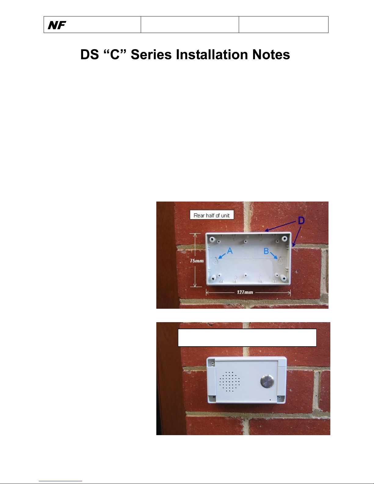
1.2 Drill mounting holes into the rear half. The unit can be mounted horizontally or vertically.
The position of the mounting holes depends on the individual mounting situation, but they
should be drilled close to the sides of the rear half. A typical situation can use the 2 guides
(A & B) on the inside of the rear half. Note that the screws should not interfere with the
electronics when the front half is attached.
1.3 Drill a hole for the cable entry. Again, the position of this hole depends on the individual
mounting situation, but the important consideration is not to interfere with the electronics when
the front half is attached.
1.4 Mount the rear half to the wall.
Before mounting, ensure that
supplied rubber seal is mounted
between the wall and the rear
half over the cable entry hole to
prevent moisture entering the
unit. For added protection,
silicon sealant can be added
between the wall and the rear
half above and around the new
holes. (See D).
1.5 Connect cable. Connect cable
to the screw terminals, or if the
unit is supplied with cable tail,
connect the Cable Tail using
telecom crimp wire connectors
(silicon filled).
1.6 Screw the front half to the rear
half. Ensure the electronics are
not disturbed. Snap in the 4
plastic tabs to hide the screws.
1.7 Program the unit by calling into
the unit using a normal DTMF
capable telephone. See below.
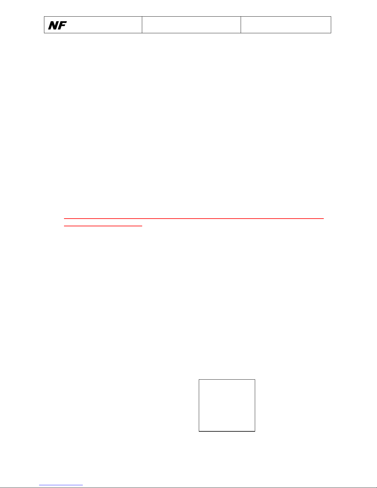
Front half of unit
Ensure button is on right (or on bottom if mounted vertically)
Page 2
comms
DS "C" Series Door Station User
Manual
Revision: D14
2 Connections
The Door Station cabling should be installed according to AS/NZ 3086 “Telecommunications
Installations – Integrated telecommunications cabling systems for small office/home office
premises”.
2.1 Line
The Line connects to the 2 wire terminal block. Connect a cable between the Front panel
unit and the PABX. The cable can pass through the premises’ Distribution Device (DD).
2.2 Units with the relay option
Refer to section 4.6 of the DS “B” series Door Station User Manual for details on the
connections to the Door Station.
The six wire terminal block has small screws and driver entry holes that can be damaged if
the right tool is not used.
IMPORTANT: Use a small straight or Philips head screw driver to avoid damage to the
6 way terminal connector.
3 Programming
Refer to DS “B” series User Manual for commands needed to program the unit.
4 Compliance
The DS ‘C’ series Door Station is fully approved and meets the Australian Communications
Authority (ACA) requirements for Electrical Safety, Telecommunications and Electromagnetic
Compatibility (EMC). Warning: The DS ‘C’ Series Door Station has been designed for
connection to a PABX and is not approved for direct connection to the Public Switched
Telephone Network (PSTN).
Copyright 2010
NF Communications
NFcomms
Designed and Manufactured
in Australia by NF
Communications P/L
Anthony Street
Ormond VIC 3204
Tel: 03 9525 7195
Fax: 03 9525 7196
Web: www.nfcomms.com.au
 Loading...