

Page 1
HVA4321
10kV AC/DC AMPLIFIER
10kV AC/DC AMPLIFIER
HVA4321
INSTRUCTION MANUAL
NF Corporation
Page 2

Page 3

10kV AC/DC AMPLIFIER
HVA4321
Instruction Manual
DA00012063-001
This unit generates high voltage. Incorrect operation may result in death
or injury. To prevent death or injury, please read this manual carefully.
Keep this manual near the unit so that operators may read at any time.
Page 4

Page 5
HVA4321
i
!
⎯ Preface ⎯
Thank you for purchasing the 10 kV AC/DC amplifier.
To ensure safe and proper use of this electric equipment, please read first INSTRUCTIONS FOR SAFE
USE on the following pages.
Caution Symbols Used in This Manual
The following caution symbols are used in this manual. Be sure to observe these caution symbols and their
contents to ensure the safety of the user and avoid damage to the equipment.
This mark indicates information for the avoidance of a hazard such as electric shock that may endanger
human life or cause injury during handling of the equipment.
This mark indicates information for the avoidance of damage to the equipment during handling.
This manual has the following chapter organization.
If reading this manual for the first time, start from Chapter 1.
1. OVERVIEW
Describes various items that must be checked prior to using this product.
2. PREPARATIONS BEFORE USE
Describes various cautions regarding preparations to be made before installation or operation.
3. PART NAMES AND FUNCTIONS
Describes functions, movements and basic operations for knobs on the panel. Read this manual
while operating the unit.
4. OPERATION
Describes operation of this product.
5. REPRESENTATIVE CHARACTERISTICS
Describes representative characteristic of this product.
6. TROUBLESHOOTING
Describes corrective actions when problems occur.
7. MAINTENANCE
Describes basic operation tests and daily maintenance procedures.
8. SPECIFICATIONS
Lists the specifications (functions and performance).
!
CAUTION
WARNING
Page 6

HVA4321
ii
⎯ Safety Precautions ⎯
To ensure safe use, be sure to observe the following warnings and cautions.
NF Corporation shall not be held liable for damages that arise from a failure to observe these warnings and
cautions.
This product is a Class 1 product (with protective conductor terminal) that conforms to the JIS and IEC
insulation standards.
Be sure to observe the contents of this instruction manual.
This instruction manual contains information for the safe operation and use of this product.
Be sure to read this information first before using this product.
All the warnings in the instruction manual must be heeded to prevent hazards that may cause major
accidents.
Be sure to ground the product.
This product uses a line filter and must be grounded to avoid the risk of electric shock.
To prevent electric shock, be sure to safely implement grounding according to Japanese Standard for
Electrical Equipment Technology D (Type 3) or higher.
When the 3-pin power plug is connected to the 3-pin power outlet with protective ground contact, this
product is automatically grounded.
To use 3-pin 2-pin conversion adapter, be sure to connect the ground line (green) of the conversion
adapter to the ground terminal near the outlet.
If the ground terminal is available at the back panel, the terminal may be grounded with a wire equivalent
to or larger than the thickness of the power cable.
Check the power supply voltage.
This product operates on the power supply voltage indicated in Grounding and Power Supply Connection
in this instruction manual.
Prior to connecting the power supply, check that the voltage of the power supply matches the rated power
supply of the product.
Observe the fuse rating.
Fire may occur. Use the rated fuse specified in Grounding and Power Supply Connection in the
instruction manual.
When the fuse is replaced, be sure to disconnect the power cable from the outlet.
In case of suspected anomaly
If this product emits smoke, an abnormal smell, or abnormal noise, immediately disconnect the power
cable and stop operation.
If such an anomaly occurs, do not use this product until it has been repaired, and immediately report the
problem to the location of purchase (either NF Corporation or your distributor).
Do not use this product when gas is present.
Otherwise, it may cause an explosion.
Page 7
HVA4321
iii
!
!
!
Do not remove the cover.
This product contains high-voltage parts. Absolutely never remove its cover. Even when the inside of this
product needs to be inspected, do not touch the inside.
All such inspections are to be performed by service technicians designated by NF Corporation.
Do not modify this product.
Absolutely never modify this product, as this may cause new hazards and may disqualify this product
from repair in case of failure.
Safety-related symbols
The general definitions of the safety-related symbols used on this product and in the instruction manual
are provided below.
Instruction manual reference symbol
This symbol is displayed to alert the user to potential danger and refer him/her to
the instruction manual.
Electric shock danger symbol
This symbol indicates locations that present a risk of electric shock under specific
conditions.
Protective terminal grounding symbol
This symbol indicates terminals that require grounding to prevent electric shock.
Before operation of the unit, be sure to connect this terminal to the ground of type
3 or higher. (When the 3-pin power cable is connected to the 3-pin outlet, it is not
necessary to connect this ground terminal.)
Warning Symbol
This symbol indicates information for avoiding danger to human life or bodily
injury such as electric shock while handling this product.
Caution Symbol
This symbol indicates information for preventing damage to the product when
handling it.
Other symbols
This symbol indicates the "ON" position of the power switch.
This symbol indicates the "OFF" position of the power switch.
This symbol indicates that the external conductor of the connector is connected to the
case.
This symbol indicates that the external conductor of the connector is connected to the
signal ground.
CAUTION
WARNING
Page 8

HVA4321
iv
Page 9

HVA4321
v
Contents
Page
1. Overview
1.1 Features................................................................................................................. 1-1
1.2 Function description and block diagram ............................................................ 1-3
1.2.1 Function description .................................................................................................... 1-3
1.2.2 Block diagram ............................................................................................................... 1-4
Preparations before use
2.1 Before using the HVA4321.................................................................................... 2-1
2.2 Installation............................................................................................................. 2-2
2.3 Grounding and power supply connection........................................................... 2-3
3. Nomenclature and functions
3.1 Signal system........................................................................................................ 3-1
3.1.1 Internal DC bias signal source..................................................................................... 3-1
3.1.2 External bias signal input ............................................................................................ 3-1
3.1.3 External signal input .................................................................................................... 3-2
3.1.4 Input signal ON/OFF ..................................................................................................... 3-2
3.2 Amplifier ................................................................................................................ 3-4
3.2.1 Amplifier operation mode ............................................................................................ 3-4
3.2.2 Amplifier control........................................................................................................... 3-6
3.2.3 Output ........................................................................................................................... 3-9
3.3 Monitor and control signal system .................................................................... 3-11
3.3.1 Monitor .........................................................................................................................3-11
3.3.2 Control signal system ................................................................................................ 3-12
3.4 Power supply items ............................................................................................ 3-17
3.5 Panel drawing ..................................................................................................... 3-18
3.5.1 Front panel.................................................................................................................. 3-18
3.5.2 Rear panel................................................................................................................... 3-19
4. Operation method
4.1 Operation example in constant voltage mode ....................................................4-1
4.1.1 Panel setting ................................................................................................................. 4-3
4.1.2 Connection of signal source and connection of load................................................. 4-6
4.1.3 Power supply and internal high voltage DC power supply......................................... 4-9
4.1.4 Signal output and adjustment.....................................................................................4-11
4.1.5 Signal OFF .................................................................................................................. 4-13
4.2 Operation example in constant current mode (total) ....................................... 4-14
4.2.1 Panel setting ............................................................................................................... 4-16
4.2.2 Connection of signal source and connection of load............................................... 4-19
4.2.3 Power supply and internal high voltage DC power supply....................................... 4-22
4.2.4 Signal output and adjustment.................................................................................... 4-24
4.2.5 Signal OFF .................................................................................................................. 4-26
Page 10

Contents
HVA4321
vi
4.3 Operation example in constant current mode (load)........................................ 4-27
4.3.1 Panel setting ............................................................................................................... 4-29
4.3.2 Connection of signal source and connection of load............................................... 4-32
4.3.3 Power supply and internal high voltage DC power supply....................................... 4-35
4.3.4 Signal output and adjustment.................................................................................... 4-37
4.3.5 Signal OFF .................................................................................................................. 4-39
4.4 Operation example in constant current + constant voltage mode .................. 4-40
4.4.1 Panel setting ............................................................................................................... 4-42
4.4.2 Connection of signal source and connection of load............................................... 4-45
4.4.3 Power supply and internal high voltage DC power supply....................................... 4-48
4.4.4 Signal output and adjustment.................................................................................... 4-50
4.4.5 Signal OFF .................................................................................................................. 4-52
4.5 Change of load and power OFF ......................................................................... 4-53
4.5.1 Change of load ........................................................................................................... 4-53
4.5.2 Power supply OFF ...................................................................................................... 4-56
4.6 Remote control.................................................................................................... 4-57
4.6.1 Remote control ........................................................................................................... 4-57
4.6.2 Panel setting for use of remote control..................................................................... 4-58
5. Representative characteristics
5.1 Measuring method ................................................................................................ 5-1
5.2 Characteristics in constant voltage mode .......................................................... 5-3
5.2.1 Frequency characteristics ........................................................................................... 5-3
5.2.2 Step response............................................................................................................... 5-4
5.3 Characteristics in constant current mode .......................................................... 5-5
5.3.1 Frequency characteristics ........................................................................................... 5-5
5.3.2 Step response............................................................................................................... 5-6
5.4 Characteristics in constant current and constant voltage mode ...................... 5-7
5.4.1 Frequency characteristics ........................................................................................... 5-7
5.5 Characteristics of voltage monitor and current monitor ................................... 5-8
5.5.1 Frequency characteristics ........................................................................................... 5-8
5.6 Others .................................................................................................................... 5-9
5.6.1 Delay of output signal for input signal........................................................................ 5-9
5.6.2 Step response due to difference of amplitude .......................................................... 5-10
6. Troubleshooting
6.1 When suspecting a fault....................................................................................... 6-1
7. Maintenance
7.1 Daily maintenance ................................................................................................ 7-1
7.2 Inspection .............................................................................................................. 7-2
7.3 When the unit is not used for a long time........................................................... 7-2
7.4 Performance test................................................................................................... 7-3
7.4.1 Test of constant voltage mode..................................................................................... 7-3
7.4.2 Test of constant current mode..................................................................................... 7-4
Page 11

Contents
HVA4321
vii
8. Specification
8.1 Signal area ............................................................................................................ 8-1
8.2 Amplifier ................................................................................................................ 8-2
8.2.1 Characteristics of constant voltage mode .................................................................. 8-2
8.2.2 Characteristics of constant current mode................................................................... 8-4
8.3 Output area............................................................................................................ 8-5
8.4 Monitor output ...................................................................................................... 8-5
8.5 Other input/output signal ..................................................................................... 8-6
8.6 Protection circuit .................................................................................................. 8-7
8.7 Others .................................................................................................................... 8-7
8.8 General items ........................................................................................................ 8-8
Page 12

HVA4321
viii
Figures
Page
Figure1-1. HVA4321 Block diagram................................................................................................. 1-4
Figure2-1. Check of power OFF ...................................................................................................... 2-3
Figure2-2. Check of internal high voltage DC power OFF ............................................................. 2-3
Figure2-3. Inserting power cable connector................................................................................... 2-4
Figure2-4. Using conversion connector .........................................................................................2-4
Figure2-5. Casing ground terminal ................................................................................................. 2-5
Figure3-1. Internal DC bias signal source ...................................................................................... 3-4
Figure3-2. External DC bias input ................................................................................................... 3-1
Figure3-3. External signal input ...................................................................................................... 3-2
Figure3-4. Signal ON/OFF switch .................................................................................................... 3-2
Figure3-5. Operation mode switch .................................................................................................. 3-4
Figure3-6. Limiter and response..................................................................................................... 3-6
Figure3-7. Operation of voltage limiter (1) ..................................................................................... 3-6
Figure3-8. Operation of voltage limiter (2) ..................................................................................... 3-6
Figure3-9. Operation of current limiter ........................................................................................... 3-7
Figure3-10. Response function in constant voltage mode .............................................................. 3-8
Figure3-11. Response function in constant current mode .............................................................. 3-8
Figure3-12. Output area..................................................................................................................... 3-9
Figure3-13. Power supply and internal high voltage DC power ...................................................... 3-9
Figure3-14. Return terminal ............................................................................................................ 3-10
Figure3-15. Monitor output...............................................................................................................3-11
Figure3-16. Status signal output ......................................................................................................3-11
Figure3-17. Remote/local settings .................................................................................................. 3-12
Figure3-18. Remote control input ................................................................................................... 3-12
Figure3-19. Remote control input circuit........................................................................................ 3-13
Figure3-20. Remote control of HIGH VOLTAGE POWER SUPPLY ON/OFF ................................... 3-14
Figure3-21. Remote control of signal system ON/OFF .................................................................. 3-14
Figure3-22. Remote control of signal ON/OFF ............................................................................... 3-15
Figure3-23. Example of status contact output ............................................................................... 3-16
Figure4-1. Constant voltage mode (total mode) ............................................................................. 4-1
Figure4-2. Constant voltage mode (load mode) ............................................................................. 4-2
Figure4-3. Internal high voltage DC power OFF ............................................................................. 4-3
Figure4-4. Switch settings............................................................................................................... 4-3
Figure4-5. Output mode settings .................................................................................................... 4-4
Figure4-6. Local settings................................................................................................................. 4-4
Figure4-7. Limiter settings .............................................................................................................. 4-5
Figure4-8. Current monitor mode settings ..................................................................................... 4-5
Figure4-9. Response settings ......................................................................................................... 4-6
Figure4-10. Connection of external signal source signal ................................................................ 4-6
Page 13

Figures
HVA4321
ix
Figure4-11. Connection of monitor ................................................................................................... 4-7
Figure4-12. Connection of output cable ........................................................................................... 4-7
Figure4-13. Power supply.................................................................................................................. 4-9
Figure4-14. Internal high voltage DC power ON............................................................................. 4-10
Figure4-15. Using internal DC bias signal .......................................................................................4-11
Figure4-16. Using external oscillator.............................................................................................. 4-12
Figure4-17. Using external DC bias signal ..................................................................................... 4-12
Figure4-18. Total mode .................................................................................................................... 4-15
Figure4-19. Internal high voltage DC power OFF ........................................................................... 4-16
Figure4-20. Switch settings............................................................................................................. 4-16
Figure4-21. Output mode settings .................................................................................................. 4-17
Figure4-22. Local settings............................................................................................................... 4-17
Figure4-23. Limiter settings ............................................................................................................ 4-18
Figure4-24. Current monitor mode settings ................................................................................... 4-18
Figure4-25. Response settings ....................................................................................................... 4-19
Figure4-26. Connection of external signal source signal .............................................................. 4-19
Figure4-27. Connection of monitor ................................................................................................. 4-20
Figure4-28. Connection of output cable ......................................................................................... 4-20
Figure4-29. Power supply................................................................................................................ 4-22
Figure4-30. Internal high voltage DC power ON............................................................................. 4-23
Figure4-31. Using internal DC bias signal ...................................................................................... 4-24
Figure4-32. Using external oscillator.............................................................................................. 4-25
Figure4-33. Using external DC bias signal ..................................................................................... 4-25
Figure4-34. Load mode.................................................................................................................... 4-28
Figure4-35. Internal high voltage DC power OFF ........................................................................... 4-29
Figure4-36. Switch settings............................................................................................................. 4-29
Figure4-37. Output mode settings .................................................................................................. 4-30
Figure4-38. Local settings............................................................................................................... 4-30
Figure4-39. Limiter settings ............................................................................................................ 4-31
Figure4-40. Current monitor mode settings ................................................................................... 4-31
Figure4-41. Response settings ................................................................................................
....... 4-32
Figure4-42. Connection of external signal source signal .............................................................. 4-32
Figure4-43. Connection of monitor ................................................................................................. 4-33
Figure4-44. Connection of output cable ......................................................................................... 4-33
Figure4-45. Power supply................................................................................................................ 4-35
Figure4-46. Internal high voltage DC power ON............................................................................. 4-36
Figure4-47. Using internal DC bias signal ...................................................................................... 4-37
Figure4-48. Using external oscillator.............................................................................................. 4-38
Figure4-49. Using external DC bias signal ..................................................................................... 4-38
Figure4-50. Constant current constant voltage mode (total mode)............................................... 4-41
Figure4-51. Constant current constant voltage mode (load mode) ............................................... 4-41
Figure4-52. Internal high voltage DC power OFF ........................................................................... 4-42
Figure4-53. Switch settings............................................................................................................. 4-42
Page 14

Figures
HVA4321
x
Figure4-54. Output mode settings .................................................................................................. 4-43
Figure4-55. Local settings............................................................................................................... 4-43
Figure4-56. Limiter settings ............................................................................................................ 4-44
Figure4-57. Current monitor mode settings ................................................................................... 4-44
Figure4-58. Response settings ....................................................................................................... 4-45
Figure4-59. Connection of external signal source signal .............................................................. 4-45
Figure4-60. Connection of monitor ................................................................................................. 4-46
Figure4-61. Connection of output cable ......................................................................................... 4-47
Figure4-62. Power supply................................................................................................................ 4-48
Figure4-63. Internal high voltage DC power ON............................................................................. 4-49
Figure4-64. Using internal DC bias signal ...................................................................................... 4-50
Figure4-65. Using external oscillator.............................................................................................. 4-51
Figure4-66. Using external DC bias signal ..................................................................................... 4-51
Figure4-67. Input signal OFF........................................................................................................... 4-53
Figure4-68. Internal high voltage power supply OFF ..................................................................... 4-53
Figure4-69. Checking items before power OFF .............................................................................. 4-54
Figure4-70. POWER OFF ................................................................................................................. 4-54
Figure4-71. Removing high voltage cable ...................................................................................... 4-55
Figure4-72. Remote control............................................................................................................. 4-57
Figure4-73. Remote control switch................................................................................................. 4-58
Figure5-1. Compensation of probe ................................................................................................. 5-1
Figure5-2. Measuring method of output voltage ............................................................................ 5-1
Figure5-3. Measuring method of output current ............................................................................ 5-2
Figure5-4. Frequency characteristics in constant voltage mode without load ............................. 5-3
Figure5-5. Frequency characteristics in constant voltage mode with capacity load ................... 5-3
Figure5-6. Step response in constant voltage mode without load ................................................ 5-4
Figure5-7. Step response in constant voltage mode with 35 pF load ........................................... 5-4
Figure5-8. Frequency characteristics in constant current (TOTAL) mode.................................... 5-5
Figure5-9. Frequency characteristics in constant current (LOAD) mode ..................................... 5-5
Figure5-10. Step response in constant current mode with 1 MΩload ............................................. 5-6
Figure5-11. Frequency characteristics in constant current (TOTAL) + constant voltage mode .... 5-7
Figure5-12. Frequency characteristics in constant current (LOAD) + constant voltage mode ...... 5-7
Figure5-13. Frequency characteristics of voltage monitor.............................................................. 5-8
Figure5-14. Frequency characteristics of current monitor .............................................................. 5-8
Figure5-15. Delay of input/output signal .......................................................................................... 5-9
Figure5-16. Step response in constant voltage mode.................................................................... 5-10
Figure7-1. How to remove fan cover ............................................................................................... 7-1
Figure7-2. Check method of constant voltage mode ..................................................................... 7-3
Figure7-3. Check method of constant current mode...................................................................... 7-4
Figure8-1. Output current................................................................................................................ 8-2
Figure8-2. Voltage and current range allowed for output .............................................................. 8-3
Page 15

HVA4321
xi
Tables
Page
Table2-1. Accessories.................................................................................................................... 2-3
Table3-1. Logic of HIGH VOLTAGE POWER SUPPLY ON/OFF ...................................................... 3-3
Table3-2. Logic of signal system ON/OFF signal ......................................................................... 3-3
Table3-3. Logic of SIGNAL ON/OFF signal.................................................................................... 3-3
Table3-4. Status contact output signal ......................................................................................... 3-3
Page 16

Figures
HVA4321
xii
Page 17
1. Overview
1.1 Features
・・・・・・・・・・・・・・・・・・・・・・・・・・・・・・・・・・・・・・・・・
1-1
1.2 Function description and block diagram
・・・・・・・・・・・・・・
1-3
1.2.1 Function description
・・・・・・・・・・・・・・・・・・・・・・・・・・・
1-3
1.2.2 Block diagram
・・・・・・・・・・・・・・・・・・・・・・・・・・・・・・・・
1-4
Page 18

HVA4321
1-2
Page 19

1.1 Features
HVA4321
1-1
1.1 Features
The HVA4321 10 kV AC/DC amplifier is a constant voltage/constant current amplifier capable of
±10 kVpk and ±10 mApk.
Since the unit has a DC bias signal source, it can be used as a DC power supply that is individually
capable of high voltage output. Since external AC signal and DC signal input are allowed, it can
also be used as an amplifier capable of high voltage output.
Constant voltage/constant current amplifier
The unit can be used as a constant voltage amplifier or a constant current amplifier.
The unit can also be set as a constant voltage amplifier for DC signal and a constant
current amplifier for AC signal.
Built-in DC signal source
The unit has a built-in DC bias signal source.
With external signal input terminals
The unit can be connected to the external signal source for two systems.
Excellent characteristics with large amplitude
In constant voltage mode, 10 kVpk output up to 7 kHz is available.
In constant current mode, 10 kVpk output up to 4 kHz is available.
(with resistance load for both modes)
With output limiter function
Output voltage limiter and output current limiter functions are available.
High slew rate
In the constant voltage amplifier, the slew rate of 500 V/Ω is achieved.
Two types of current mode
In the constant current amplifier, two types of modes are available; the total mode that gives the
set current output from the amplifier and the load mode that gives correct current set to the load
by compensating the current leaking from stray capacitance of a wire along the path.
Step response waveform adjusting function
For a step signal, fine adjustment of the response waveform can be made.
Correct monitor output
Output voltage and output current can be correctly monitored.
(Voltage monitor gain: 1/1000, Current monitor gain: 1 V/10 mA)
Page 20

1.1 Features
HVA4321
1-2
Visual display of high voltage output
During high voltage output, the LED around the output connector lights and the revolution
changes depending on the output voltage level.
Remote control is capable.
Signals can be turned ON/OFF with an external control signal.
Page 21

1.2 Function description and block diagram
HVA4321
1-3
1.2 Function description and block diagram
1.2.1 Function description
Major functions of this unit are classified into the following:
・Signal system
・Amplifier stage
・Detection system
・High voltage power supply
・External control system
Signal system
The following three types of signals can be used as the signal sources:
・Signal source built into the unit that gives the DC output (DC BIAS)
・Signal from external oscillator (OSC INPUT)
・Signal from external DC signal source (EXT DC BIAS INPUT)
These signals can be used simultaneously. Signal is internally added and the input is given to the
amplifier stage.
Amplifier stage
Input signals are separated into positive and negative signals, and each signal is transmitted to
the high voltage amplifier stage through an optical fiber.
Detection system
Output voltage and output current are correctly detected by independently detecting and
combining DC and AC components.
High voltage power supply
The unit is using ±12 kV power supply to obtain the output of 10 kVpk. This power supply can
be individually turned ON/OFF for safety.
External control system
The signal source can be turned ON/OFF with an external contact signal or TTL level signal.
Page 22
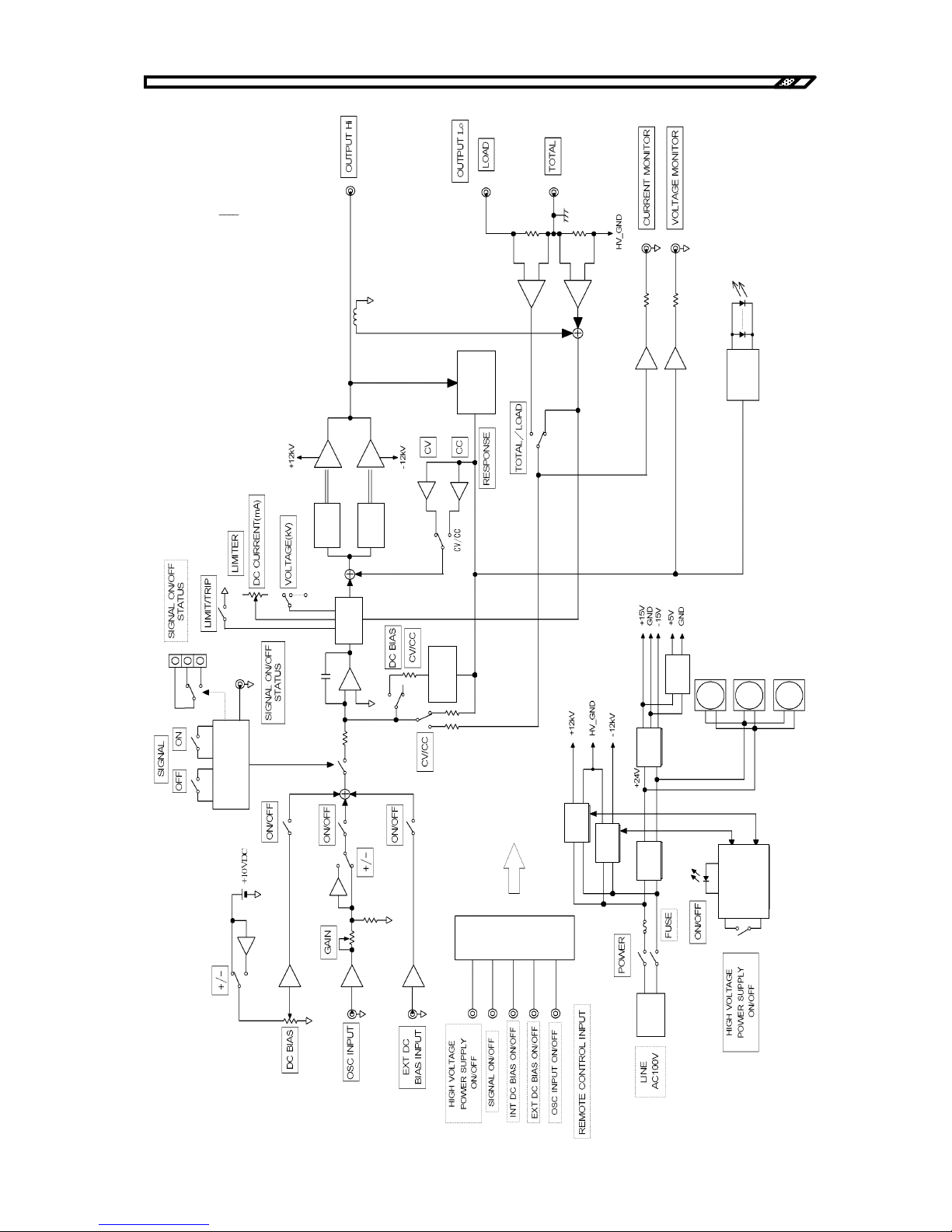
1.2 Function description and block diagram
HVA4321
1-4
Fig. 1-1
HVA4321 Block diagram
Driver
Protection
circui
t
Driver
High voltage amplifier
Current sensor
Optical fiber
DC detection
circuit
Driver
Voltage
detection
circuit
External
control
circuit
Control signal for
remote control
Power
supply
Power
supply
Power
supply
Power
supply
Line
filter
Control power
supply
FAN
High voltage
power supply
control circuit
Power
supply
Display
circuit
LED indicator
ON/OFF
control circuit
1.2.2 Block diagram
Page 23
2. Preparations before use
2.1 Before using the HVA4321
・・・・・・・・・・・・・・・・・・・・・・・・・
2-1
2.2 Installation
・・・・・・・・・・・・・・・・・・・・・・・・・・・・・・・・・・・・・・・
2-2
2.3 Grounding and power supply connection
・・・・・・・・・・・・・
2-3
Page 24

Page 25
2.1 Before using the HVA4321
HVA4321
2-1
!
2.1 Before using the HVA4321
Safety check
Before using the HVA4321, read the following items in the instruction manual:
[INSTRUCTIONS FOR SAFE USE] (Described at the beginning of this instruction manual.)
[2.3 Grounding and connection of power supply]
Appearance and accessories check
Removal of product
Remove the product out of the box. If unusual statues (damage or dent) are observed
on the cardboard box, make sure that the product is not adversely affected.
Check of appearance
Make sure that there is no damage or dent on the panel surface, knob or connector.
Check of accessories
Accessories of this product are as shown below. Make sure that the quantity is
sufficient or that there is no faulty part.
Table2-1. Accessories
・Instruction manual (HVA4321 instruction manual)
・Power cable (10A, 125V, 2 m, 3 poles)
・Fuse (time lag, 10 A/250V,φ2 x 20 mm)
・High voltage cable A600B80 (approx. 2 m by ALDEN)
・Ground cable (0.75 mm2 with M6 crimp terminal, approx. 4 m, black)
・Ground cable (0.75 mm2 with M6 crimp terminal, approx. 4 m, white)
If appearance of the product shows unusual damage or if accessories are insufficient,
contact us or our agent.
This product contains high-voltage parts. Absolutely never remove its cover.
Otherwise, touching the internal circuit may result in death by electric shock.
WARNING
Page 26
2.2 Installation
HVA4321
2-2
!
2.2 Installation
Before installation
This product has a positive air conditioning system with back intake and side exhaust
fans to cool the inner parts. To allow ventilation of air, install this product with
the side and the back by 30 cm or more apart from walls.
The range of ambient temperature and humidity for this product is as follows:
Performance assurance :Temperature 5℃to 35℃ Humidity 45% to 85% (no condensation)
Operation assurance : Temperature 0℃to 40℃ Humidity 10% to 85% (no condensation)
Storage condition : Temperature -10℃to 50℃ Humidity 10% to 80% (no condensation)
Installation environment
Do not install or use the product in the following environments:
Place where there is much corrosive gas, moisture, dirt, dust or conductive particles.
Failure such corrosion or deteriorated insulation may occur.
Place where there is flammable gas.
Explosion may occur.
Place where an object may fall
Failure may occur.
Outdoor or place where the product is exposed to direct sunlight, or place near fire or heat
Performance may not be satisfied or failure may occur.
Place near electromagnetic field source, high voltage device, power line, radio transmitter, cell
phone, etc.
Unintended high voltage output may be given or noise may enter.
Place where frequent vibration occurs.
Malfunction or failure may occur.
Installation
Make sure that four legs at the bottom are on a flat place such as a desk.
Never place the unit vertically with the back facing down, horizontally with the side facing down or
up side down with the top facing down.
Do not put an object on the unit.
Do not use a radio transmitter or a cell phone around this unit. Unintended high
voltage output may be given due to radio.
WARNING
Page 27
2.3 Grounding and power supply connection
HVA4321
2-3
2.3 Grounding and power supply connection
The power supply requirements for this product are as follows:
Power supply voltage range: Single phase AC100V ±10%
Frequency range: 50/60 Hz±2 Hz
Power consumption: 800VA or less
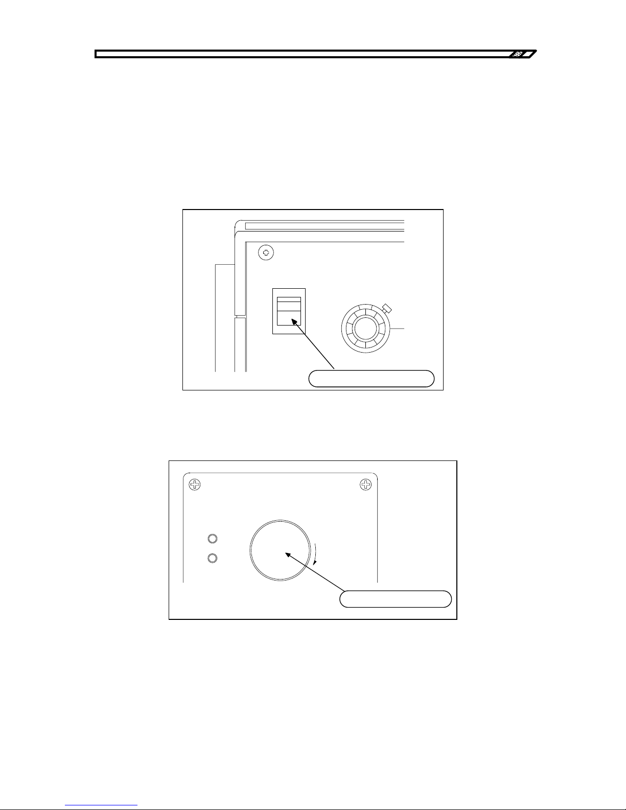
a) Check items before connection of the power cable
Make sure that the power switch on the front panel is OFF.
Figure2-1. Check of power OFF
Make sure that the HIGH VOLTAGE POWER SUPPLY switch on the front panel is pressed.
Figure2-2. Check of internal high voltage DC power OFF
POWER
DC BIAS
0-10
V
I
O
オフ であるこ と を 確認
Make sure that this is OFF.
HIGHVOLTAGE
POWER SUPPLY
PUSH OFF
PULL ON
ON
OFF
押し 込ま れて いる 状態
This must be pressed.
Page 28
2.3 Grounding and power supply connection
HVA4321
2-4
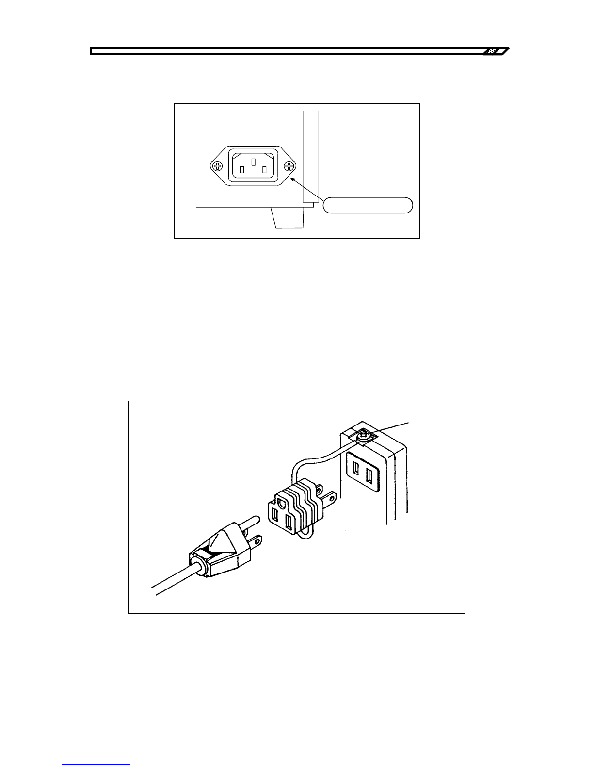
b) Connection of power cable
Insert the connector of the power cable accompanying the unit into the inlet of the back panel.
Figure2-3. Inserting power cable connector
c) Inserting the power outlet
This unit operates with the power of AC100V±10%. Insert the power cable plug into the power outlet
with the protective ground. Use the accompanying power cable and insert it into the power outlet with the
ground. The casing of the unit is then grounded.
Using 3-pin 2-pin adapter
When 3-pin 2-pin conversion adapter is sued, be sure to connect the ground wire of the conversion
adapter to the ground terminal near the outlet.
Figure2-4. Using conversion connector
~
LI NE
100V
50Hz/60Hz 800 VA MAX
コネクタを差し込む
Insert the connector.
Ground
3-pin 2-pin adapter
Page 29
2.3 Grounding and power supply connection
HVA4321
2-5
!
!
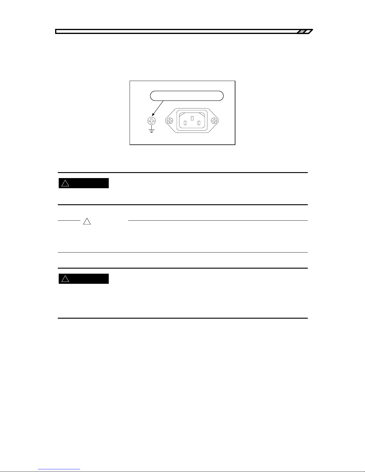
If the ground pole is not available in the adjacent area
If the power cable cannot be grounded because the ground pole is not available at
the power outlet, be sure to ground the casing ground terminal at the back with a
wire of 2 mm
2
or more.
Figure2-5. Casing ground terminal
Be sure to ground this unit for safety. Otherwise, a serious accident such as electric shock may occur.
The standard power cable accompanied has rated voltage of AC125V and rated current
of 10A. When a power cable not accompanied is used, be careful for the rated voltage
and current.
When a fuse is replaced, be sure to disconnect the power cable from the outlet. Replace it with the same
standard one.
For this product, the time lag type fuse with the rating of 10A/250V and φ2 x 20 mm is used.
!
CAUTION
WARNING
WARNING
筐体接地端子
Casing ground terminal
Page 30

2.3 Grounding and power supply connection
HVA4321
2-6
Page 31
3. Nomenclature and functions
3.1 Signal system
・・・・・・・・・・・・・・・・・・・・・・・・・・・・・・・・・・・・
3-1
3.1.1 Internal DC bias signal source
・・・・・・・・・・・・・・・・・・
3-1
3.1.2 External bias signal input
・・・・・・・・・・・・・・・・・・・・・・
3-1
3.1.3 External signal input
・・・・・・・・・・・・・・・・・・・・・・・・・・・
3-2
3.1.4 Input signal ON/OFF
・・・・・・・・・・・・・・・・・・・・・・・・・・
3-2
3.2 Amplifier
・・・・・・・・・・・・・・・・・・・・・・・・・・・・・・・・・・・・・・・・・
3-4
3.2.1 Amplifier operation mode
・・・・・・・・・・・・・・・・・・・・・・
3-4
3.2.2 Amplifier control
・・・・・・・・・・・・・・・・・・・・・・・・・・・・・・
3-6
3.2.3 Output
・・・・・・・・・・・・・・・・・・・・・・・・・・・・・・・・・・・・・・・
3-9
3.3 Monitor and control signal system
・・・・・・・・・・・・・・・・・・
3-11
3.3.1 Monitor
・・・・・・・・・・・・・・・・・・・・・・・・・・・・・・・・・・・・・
3-11
3.3.2 Control signal system
・・・・・・・・・・・・・・・・・・・・・・・
3-12
3.4 Power supply items
・・・・・・・・・・・・・・・・・・・・・・・・・・・・・
3-17
3.5 Panel drawing
・・・・・・・・・・・・・・・・・・・・・・・・・・・・・・・・・・
3-18
3.5.1 Front panel
・・・・・・・・・・・・・・・・・・・・・・・・・・・・・・・・・
3-18
3.5.2 Rear panel
・・・・・・・・・・・・・・・・・・・・・・・・・・・・・・・・・
3-19
Page 32

Page 33
3.1 Signal system
HVA4321
3-1
DC BIAS
0-10
V
+
-
ON
OFF
Rotary lock knob
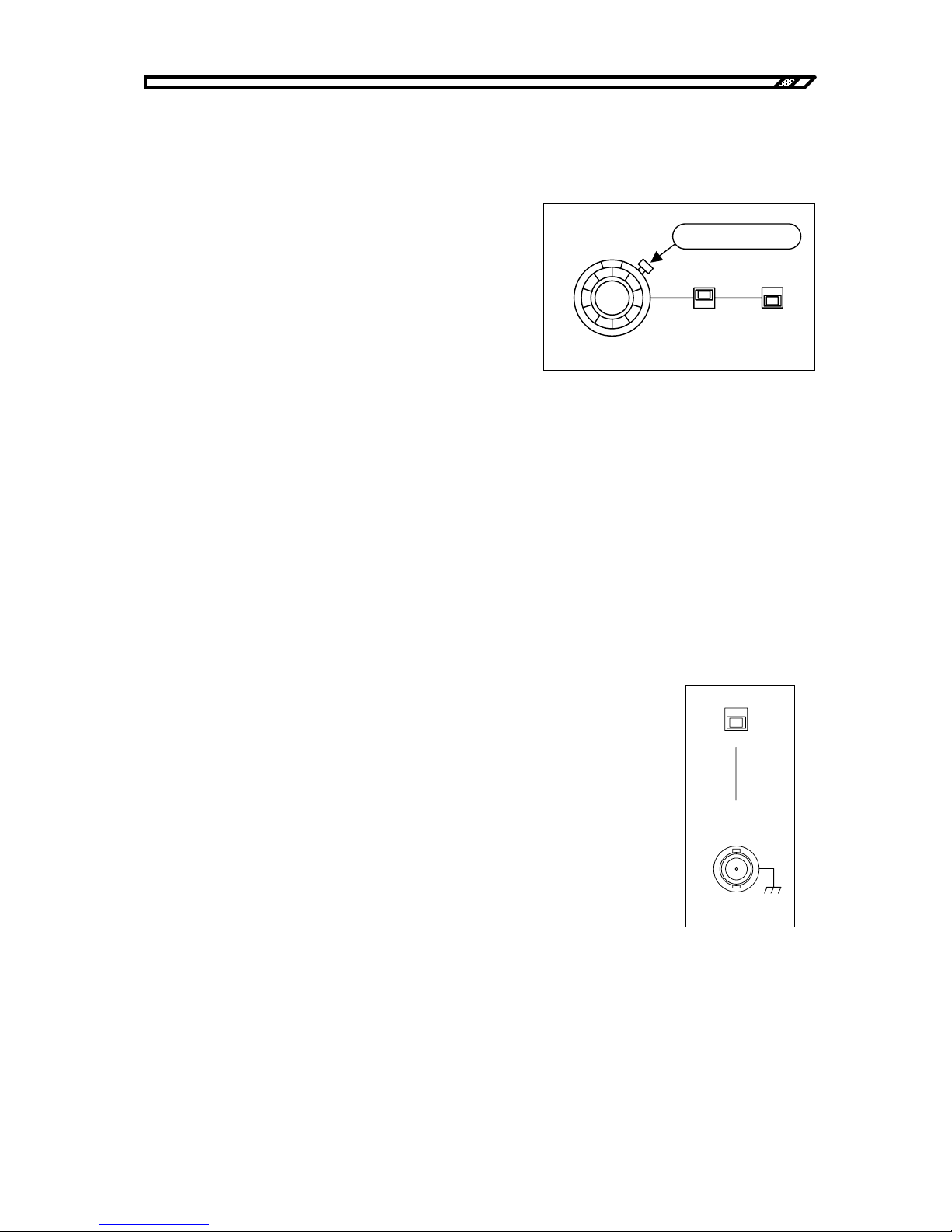
Figure3-1.
Internal DC bias signal source
3.1 Signal system
3.1.1 Internal DC bias signal source
DC BIAS
This sets the output level of the internal DC bias signal
source.
With combination of the pin switch, settings are
available in the range of:
・In constant voltage mode
0 to ±10 kV
・In current mode
0 to ±10 mA
・In constant current and constant voltage mode
0 to ±10 kV
To prevent inadvertent rotation of the dial, use the rotation lock function of the dial.
When the rotary lock knob is pressed clockwise, the dial is locked.
+/-
Polarity of the internal DC bias signal source is set. With "+", the output is positive and with "-", the
output is negative.
ON/OFF
It is the ON/OFF switch for the internal DC bias signal source. When it is ON, the internal DC bias
signal is effective.
3.1.2 External bias signal input
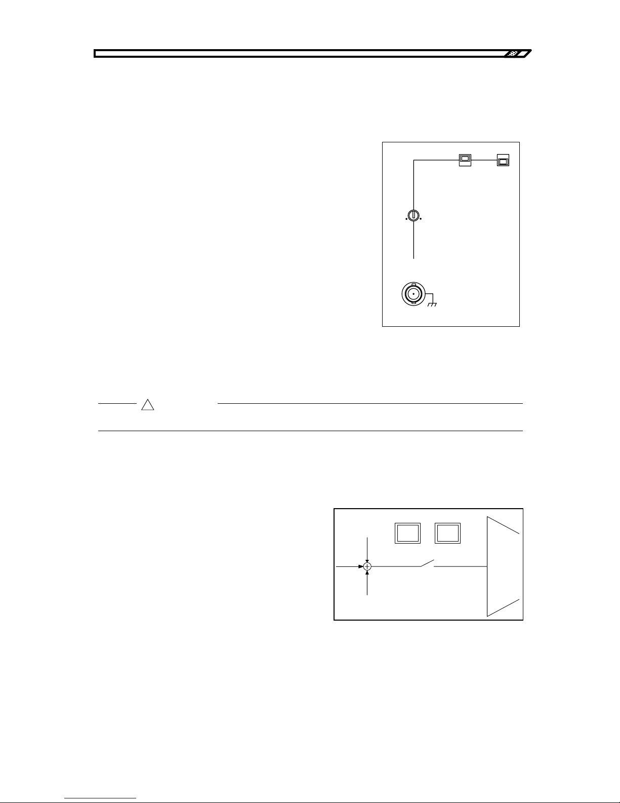
EXT DC BIAS INPUT
It is the BNC connector to give external input of the DC bias signal.
・Rated input voltage ±10 Vpk
・Input impedance 10kΩ±10%
AC signal input can also be given. But the input is only for DC. Frequency
characteristic and slew rate are inferior to the OSC input.
ON/OFF
Valid or invalid external DC bias signal is set.
When it is ON, the external DC bias signal input is valid.
Figure3-2.
External DC bias input
ON
OFF
EXT DC BIAS
INPUT
±
10V MAX
Zi n 1 0 k
Ω
Page 34
3.1 Signal system
HVA4321
3-2
3.1.3 External signal input
OSC INPUT
It is the BNC connector to give amplified input on this unit with an external
oscillator.
・Rated input voltage ±10 Vpk
・Input impedance 10 kΩ±10%
GAIN
The signal gain given to OSC INPUT can be fine adjusted in the
range of approx. ±3%.
It is turned with a flat tip screwdriver.
NORMAL/INVERT
The signal polarity in OSC INPUT is set.
In NORMAL, the input signal polarity is the same as the output
signal polarity.
In INVERT, the input signal polarity is reverse to the output
signal polarity.
Figure3-3. External signal input
ON/OFF
Valid or invalid signal in OSC INPUT is set. When it is ON, the signal in OSC INPUT is valid.
The input voltage range to OSC INPUT and EXT DC BIAS INPUT terminals is ±10V.
3.1.4 Input signal ON/OFF
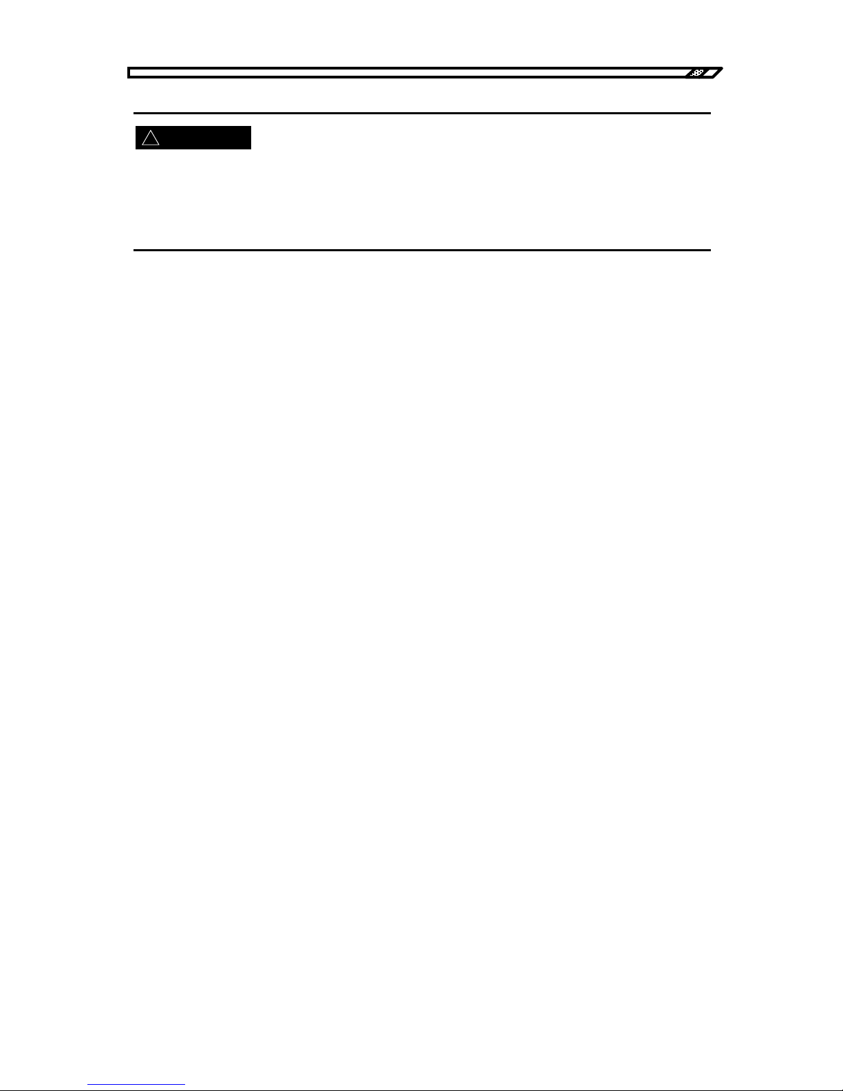
SIGNAL ON/OFF
Input to the amplifier area for INT DC BIAS, EXT
DC BIAS and OSC INPUT is switched ON/OFF.
When it is ON, each input signal is given to the high
voltage amplifier.
Figure3-4. Signal ON/OFF switch
!
CAUTION
ON
OFF
INVERT
NORMAL
GAIN
OSC
INPUT
±
10V MAX
Zi n 1 0 k
Ω
SI G N A L
OFF
ON
Page 35
3.1 Signal system
HVA4321
3-3
!
This signal ON/OFF switch has the function to set whether or not the input signal is transmitted to the high
voltage amplifier. It does not switch ON/OFF the connection between the high voltage amplifying output
and the output terminal of this unit.
The output from the high voltage amplifier is always connected tot the output terminal.
When the following operations are made in SIGNAL ON, SIGNAL OFF occurs forcibly.
・When operation mode CV/CC of the amplifier is changed
・When remote/local settings are changed
In SIGNAL OFF, the OFF LED lights. For the following cases, the OFF LED blinks:
・The HIGH VOLTAGE POWER SUPPLY switch is OFF.
(When the internal high voltage DC power supply is OFF)
When the following operations are made in SIGNAL ON, SIGNAL OFF occurs forcibly and the
LED changes from lighting to blinking.
An error during OFF turns the OFF LED from lighting to blinking.
・The fan revolution stopped.
・Temperature in the casing became high.
・Voltage of the internal control power supply became low.
・When the LIMIT/TRIP is set to TRIP, the current limiter circuit was activated.
In the cases above, SIGNAL ON cannot be recovered unless the cause is removed.
WARNING
Page 36
3.2 Amplifier
HVA4321
3-4
3.2 Amplifier
3.2.1 Amplifier operation mode
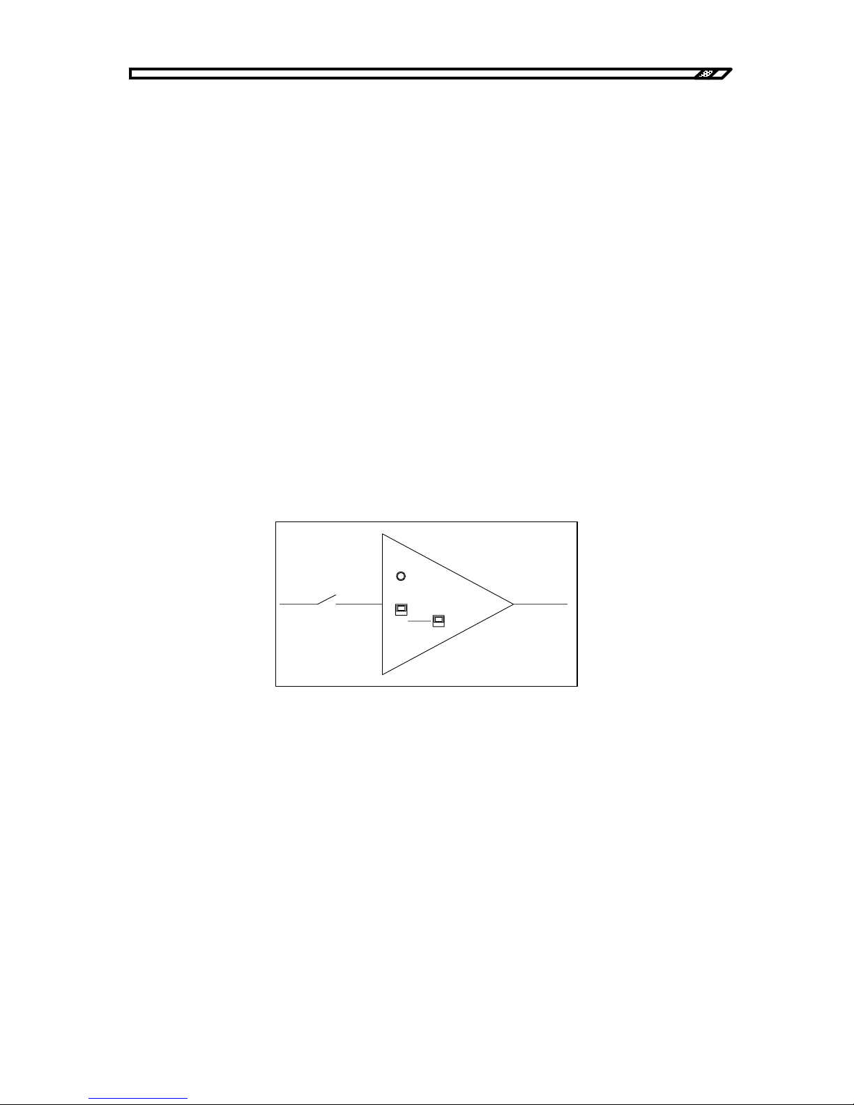
CV/CC
It is the switch to set the operation mode of the unit.
CV: Constant voltage mode
CC: Constant current mode
The gain of the high voltage amplifier is:
・Constant voltage mode: 1000V/1V
・Constant current mode: 1 mA/1V
DC BIAS CV/CC
It is the switch to set the DC signal operation mode in constant current mode.
CV: The DC signal is constant voltage mode. The AC signal is constant current mode.
CC: Both the DC signal and the AC signal are constant current mode.
For example, if a capacity load is connected in constant current mode, the capacity load has infinite
impedance for DC. DC cannot be applied in constant current.
To apply DC to a capacity load, set this switch to CV so that DC output may be given in constant
voltage mode. Then, constant DC bias can be applied to the capacity load.
In constant voltage mode, this function is invalid for either setting.
Figure3-5. Operation mode switch
OVERLOAD
CV
1kV/1V
CC
1mA/1V
DC BIAS
CV
CC
Page 37

3.2 Amplifier
HVA4321
3-5
The frequency at the boundary of constant voltage mode and constant current mode may vary
depending on the load type and value.
For resistance load
・For 250 kΩ Approx. 5 mHz or more
・For 1 MΩ Approx. 0.2 Hz or more
For capacity load
・For 16 pF Approx. 100 Hz or more
・For 100 pF Approx. 50 Hz or more
・For 1000 pF Approx. 5 Hz or more
OVERLOAD
It is the LED that lights if the unit amplifier has a fault. It lights if the unit is overloaded or the limiter
is activated.
Page 38
3.2 Amplifier
HVA4321
3-6
3.2.2 Amplifier control
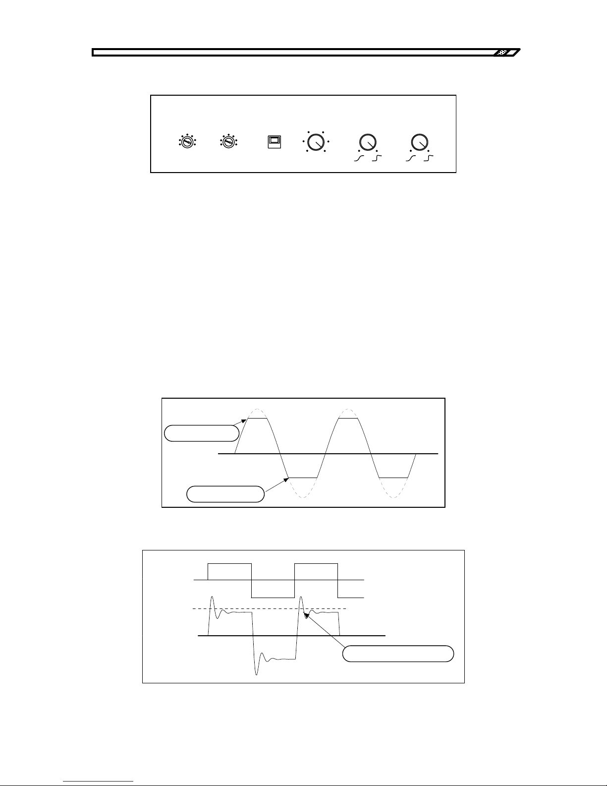
Figure3-6. Limiter and response
VOLTAGE (kV)
The limit value of the output voltage can be set in the range from ±5 kV to ±10 kV at the resolution
of 1 kV. For example, when the limit values of +8 kV for positive side and -6 kV for negative side are
satisfactory, make settings to +8 kV and -6 kV. Set the value with a flat tip screwdriver.
When MAX is set, the limit is invalid. The amplifier can give the maximum voltage output available.
In constant voltage mode
In constant voltage mode, the voltage of the internal high voltage DC power supply is limited and the
amplitude of the input signal is limited to limit the output voltage.
Use the unit paying attention to the following:
・The limit voltage for setting is only a guideline. There is approx. 0 to 100V error for the set value.
・If the output voltage is not proportional to the input voltage due to load, the value may be larger by
about 1 kV than the set value.
Figure3-7. Operation of voltage limiter (1)
Figure3-8. Operation of voltage limiter (2)
TRIP
VOLTAGE(k V)
-5
-10
MAX
5
10
MAX
LI MIT
DC CURRENT( mA)
0
10
RESPONSE
CV CC
LI MITER
+8k V
で制限される。
-6kV
で制限される。
Limited to +8 kV
Limited to -6 kV
リミッタレベル
入力電圧
出力電圧
リミッタレベルを越える。
Exceeding limiter level
Limiter level
Input voltage
Output voltage
Page 39
3.2 Amplifier
HVA4321
3-7
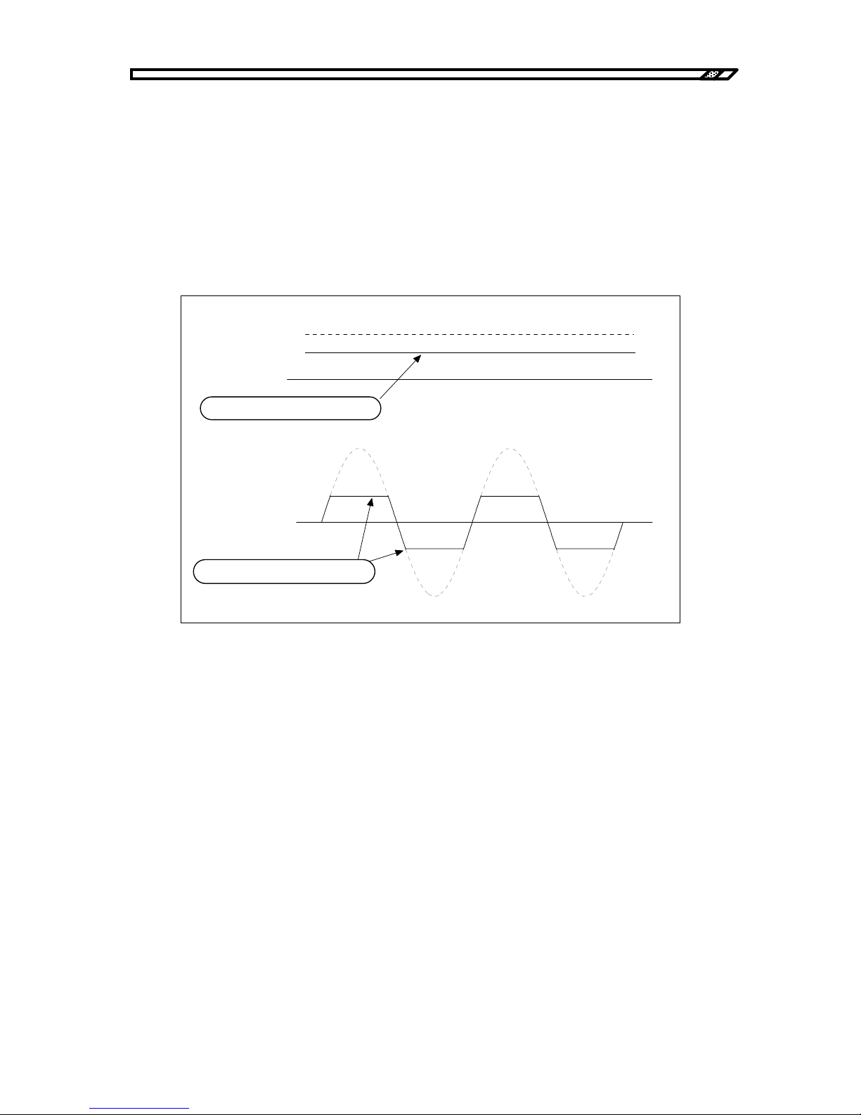
In constant current mode
In constant current mode, the voltage of the internal high voltage DC power supply is limited to limit
the output voltage. Use the unit paying attention to the following:
・Since the limit is made by current voltage, there is approx. 0 to 1 kV error for the set value.
DC CURRENT (mA)
The output current limit value is set. The limit value is common for both positive and negative and the
average current can be set in the rage from 0 mA to 10 mA.
For example, the value is set to 3 mA, the limit is +3 mA or -3 mA for DC. For AC, the average current
for positive side is 3 mA and the average current for negative side is -3 mA.
Figure3-9. Operation of current limiter
Use this current limiter paying attention to the following:
・The limit current set here is only a guideline. The setting accuracy is not high.
・It is limited not by peak current, but by average current.
・The voltage waveform of a load capacity may be non-linear due to limitation by average current,
resulting in increase of peak current.
LIMIT/TRIP
In LIMIT, the output current is limited with the setting value.
In TRIP, if the output current exceeds the set value, SIGNAL is switched OFF and the output is 0V.
平均電流
±3 mA
で制限される。
本来の出力電流レベル
直流のとき
平均電流
±3 mA
で制限される。
交流のとき
Limited by average current of ±3 m
A
Limited by average current of ±3 m
A
For AC
Original output current level
For DC
Page 40
3.2 Amplifier
HVA4321
3-8
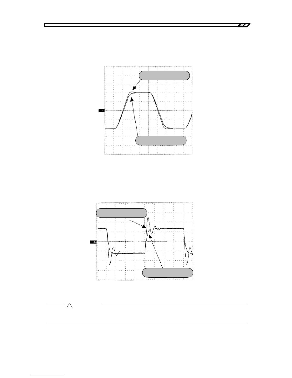
RESPONSE CV
In constant voltage mode, the step response waveform such as square wave is adjusted. As the dial is
turned toward the right, the response approaches the peak. Make adjustment for the desired response
waveform.
Figure3-10. Response function in constant voltage mode
RESPONSE CC
In constant current mode, the step response waveform such as square wave is adjusted.
As the dial is turned toward the right, the response approaches the peak. Make adjustment for the
desired response waveform.
Figure3-11. Response function in constant current mode
The step response using RESPONSE may not be sufficiently adjusted depending on setting
conditions or load conditions. In a case, oscillation may occur.
!
CAUTION
Response rightmost
Response leftmost
Response leftmost
Response rightmost
Page 41
3.2 Amplifier
HVA4321
3-9
!
3.2.3 Output
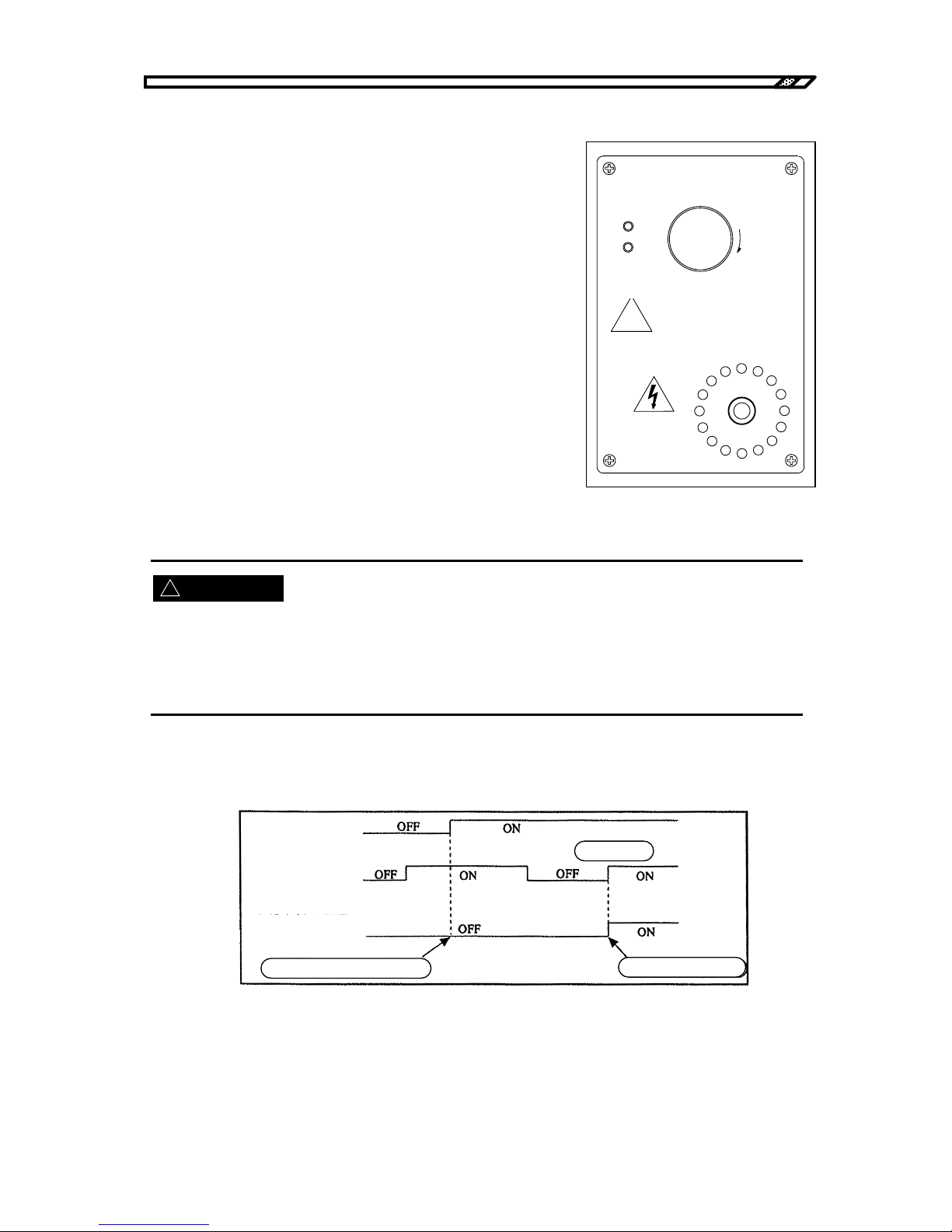
HIGH VOLTAGE POWER SUPPLY ON/OFF
Turn ON/OFF the internal high voltage DC power supply.
Press the switch until it "clicks". It is then locked and the
internal high voltage DC power supplies is OFF.
To turn it ON, turn the knob to the right. It is unlocked and the
internal high voltage DC power supply is ON.
Figure3-12. Output area
When wiring for load or output is changed, be sure to turn OFF (push) this switch. Make sure that the OFF
lamp at the left of the switch lights before work.
Do not touch load or the output cable with the internal high voltage DC power supply ON. Otherwise,
electric shock may occur.
When the power is supplied, the internal high voltage DC power supply is always OFF regardless of
ON/OFF status of this switch. If this switch is ON, turn it OFF once and turn it ON again.
Figure3-13. Power supply and internal high voltage DC power
WARNING
!
HIGHVOLTAGE
POWER SUPPLY
PUSH OFF
ON
OFF
危険防止の た め 、 出力の 配線を 変更す る と き は 必ず
上の ス イ ッ チ を 押し てH V 電源を O F F し て く だ さ い 。
DANGER
OUTPUT Hi
PULL ON
危険防止の た め、
出力中は出力ケ ー ブ ル に
絶対に触れないでく ださい。
±
10kV MAX
±
10mA MAX
Be sure to press the above switch to turn OFF the H
V
power for safety when the output wi ring is changed.
Never touch the output
cable during output for
safety.
Power switch
HIGH VOLTAGE
POWER SUPPLY
switch
Internal high voltage
power supply
Not ON
ON now
ON again
Page 42
3.2 Amplifier
HVA4321
3-10
ON/OFF
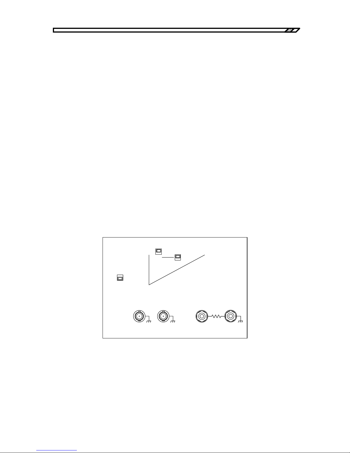
Indicates the output status of the internal high voltage DC power supply. When the high voltage DC
power supply gives high voltage output, the ON LED lights.
OUTPUT HI
It is the high voltage output terminal of the unit. Connect the accompanying special cable for use.
Output display warning lamp
When high voltage output is given, the LED around OUTPUT HI rotates and lights. The color is
yellow up to about 4.9 kV and red over this value. The rotation speed varies depending on the output
voltage level. The higher the voltage is, the faster the rotation speed is.
OUTPUT Lo TOTAL CURRENT
It is the return terminal of the high voltage output used in constant voltage mode or constant current
total mode.
OUTPUT Lo LOAD CURRENT
It is the return terminal of the high voltage output used in constant current load mode.
CURRENT SELECT
Total/load mode is set. When the unit is used in total mode, set it to TOTAL. When it is used in load
mode, set it to LOAD.
For details, refer to "4.2 Operation example in constant current mode (total)" and "4.3 Operation
example in constant current mode (load)".
Figure3-14. Return terminal
CC
1mA/1V
DC BIAS
CV
CC
CURRENT
SELECT
LOAD
TOTAL
MONITOR
1V/ 1kV
Zout 50
Ω
VOLTAGE
CURRENT
LOAD
CURRENT
TOTAL
CURRENT
OUTPUT Lo
1V/ 10mA
Zout 50
Ω
Page 43
3.3 Monitor and control signal system
HVA4321
3-11
3.3 Monitor and control signal system
3.3.1 Monitor
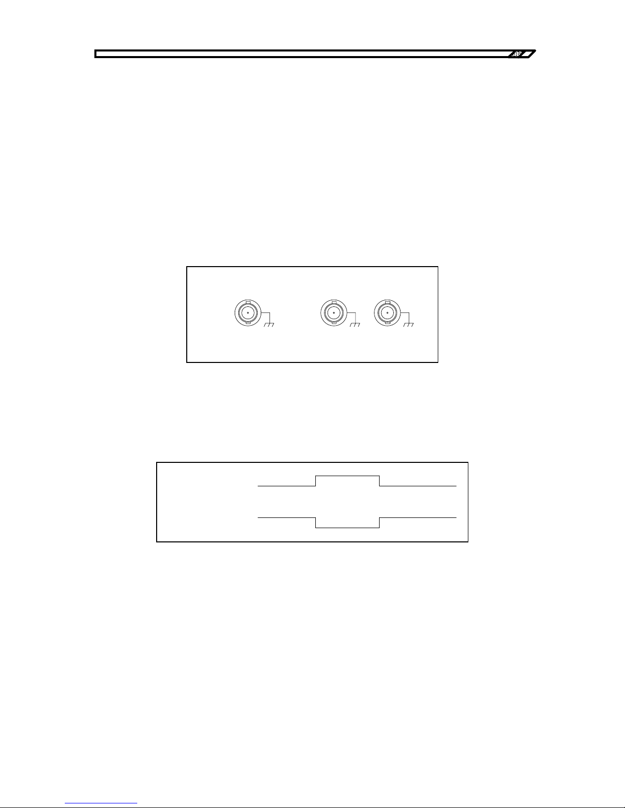
MONITOR VOLTAGE
It is the BNC connector for the monitor signal of output voltage.
・Gain: 1V/1kV
・Output impedance: 50Ω±10%
MONITOR CURRENT
It is the BNC connector for the monitor signal of output current. In constant current mode, current
selected by TOTAL/LOAD is monitored.
・Gain: 1V/10 mA
・Output impedance: 50Ω±10%
Figure3-15. Monitor output
SIGNAL ON/OFF STSTUS
It is the total level signal output that indicates SIGNAL ON/OFF status. When the signal is ON, the
level is low (approx. 0.1V or less). When the signal is OFF, the level is high (approx. 4.5V or more).
1/ Signal switch
Figure3-16. Status signal output
SIGNAL ON/OFFSTATUS
OUTPUT
MONITOR
VOLTAGE
CURRENT
TTL( Lo: ON)
Zout 10k
Ω
1V/1kV
Zout 50
Ω
1V/10mA
Zout 5 0
Ω
SI G N AL
スイッチ
SI GN AL ON/OFF
STATUS
ONOF F
LOWHIGH
HIGH
OF F
SIGNAL SWITCH
SIGNAL ON/OFF
Page 44
3.3 Monitor and control signal system
HVA4321
3-12
3.3.2 Control signal system
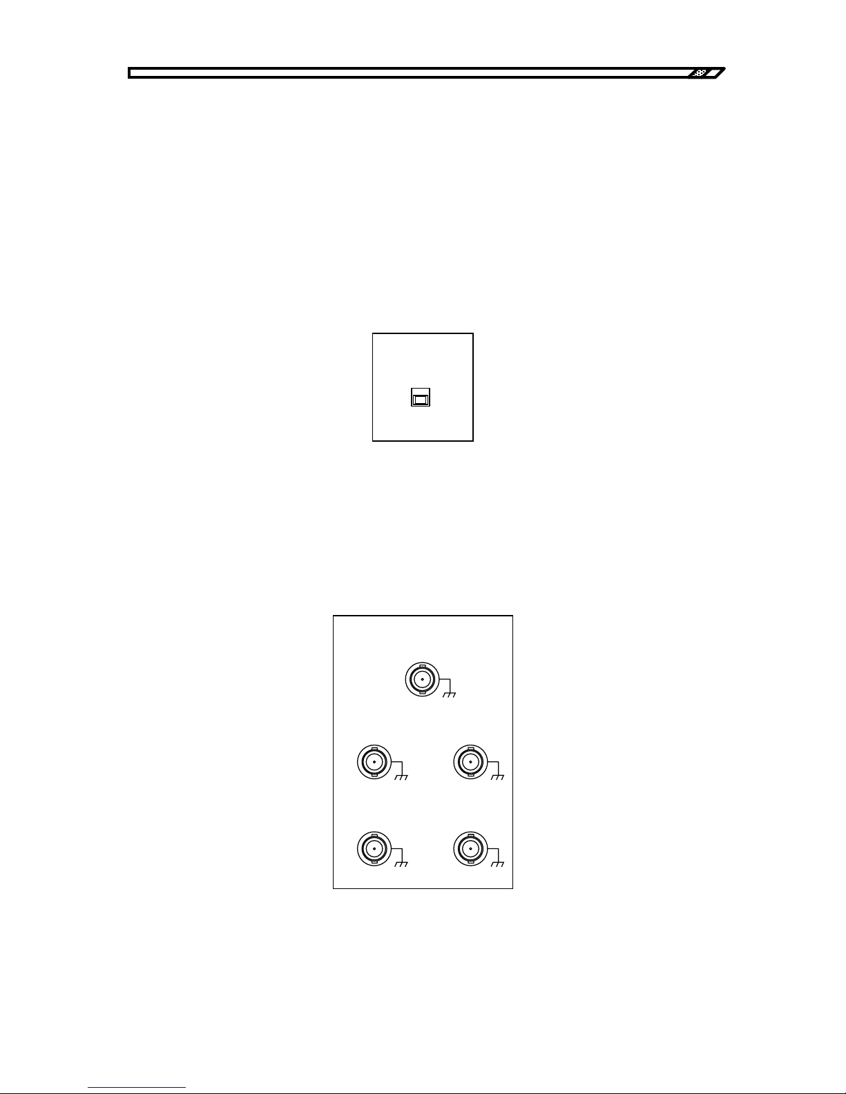
ON/OFF CONTROL
It is the remote/local setting switch. In LOCAL, the unit can be turned ON/OFF with the panel switch.
In REMOTE, the unit can be turned ON/OFF with an external signal. In REMOTE, the operation of
HIGH VOLTAGE POWER SUPPLY ON/OFF can be made with the panel.
HIGH VOLTAGE POWER SUPPLY ON/OFF Internal DC high voltage ON/OFF
SIGNAL ON/OFF High voltage amplifier input ON/OFF
OSC INPUT ON/OFF External oscillator signal ON/OFF
INT DC BIAS ON/OFF Internal DC bias signal ON/OFF
EXT DC BIAS ON/OFF External DC bias signal ON/OFF
Figure3-17. Remote/local settings
Change REMOTE/LOCAL when the signal is OFF. If REMOTE/LOCAL is changed with the signal
ON, the signal is forcibly turned OFF.
REMOTE CONTROL INPUT
It is the BNC connector to give ON/OFF control signal input when ON/OFF CONTROL is set to
REMOTE.
Figure3-18. Remote control input
INT DCBIAS ON/OFFSI GNAL ON/OFF
OSC I NP UT O N/OFF EXTDC BIASON/OFF
HIGHVOLTAGE
POWER SUPPL Y ON/OFF
TTL(Lo: ON)TTL(Lo: ON)
TTL(Lo: ON)TTL(Lo:ON)
TTL(Hi:OFF)
REMOTE CONTROL I NPUT
ON/OFF
CONTROL
REMOTE
LOCAL
Page 45
3.3 Monitor and control signal system
HVA4321
3-13
The delay time from input of the SIGNAL ON/OFF signal to actual ON/OFF is approximately
5 ㎲ or less. The delay time from input of other ON/OFF signals to actual ON/OFF is approximately
15 ㎲ or less.
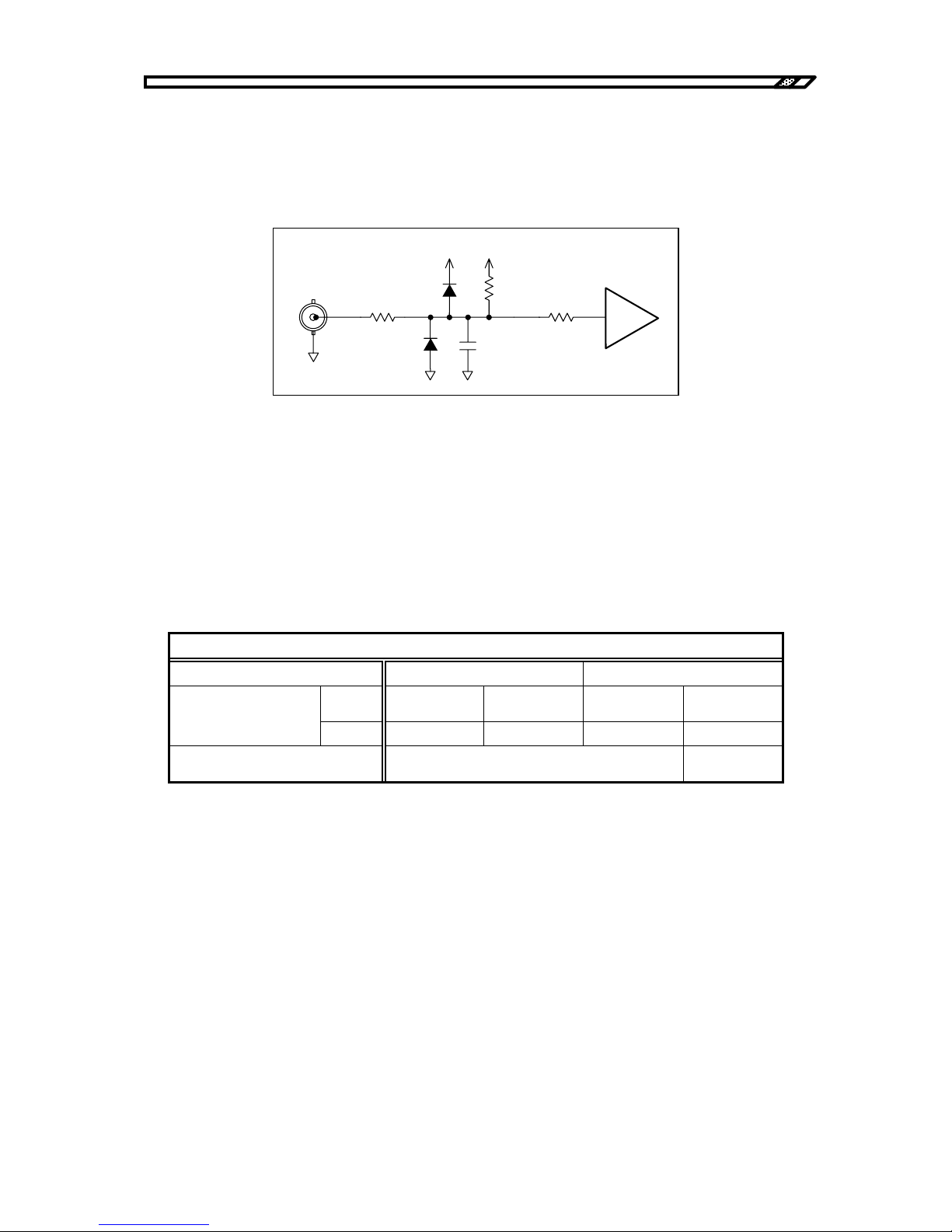
The input circuit of the remote control terminal is as follows:
Figure3-19. Remote control input circuit
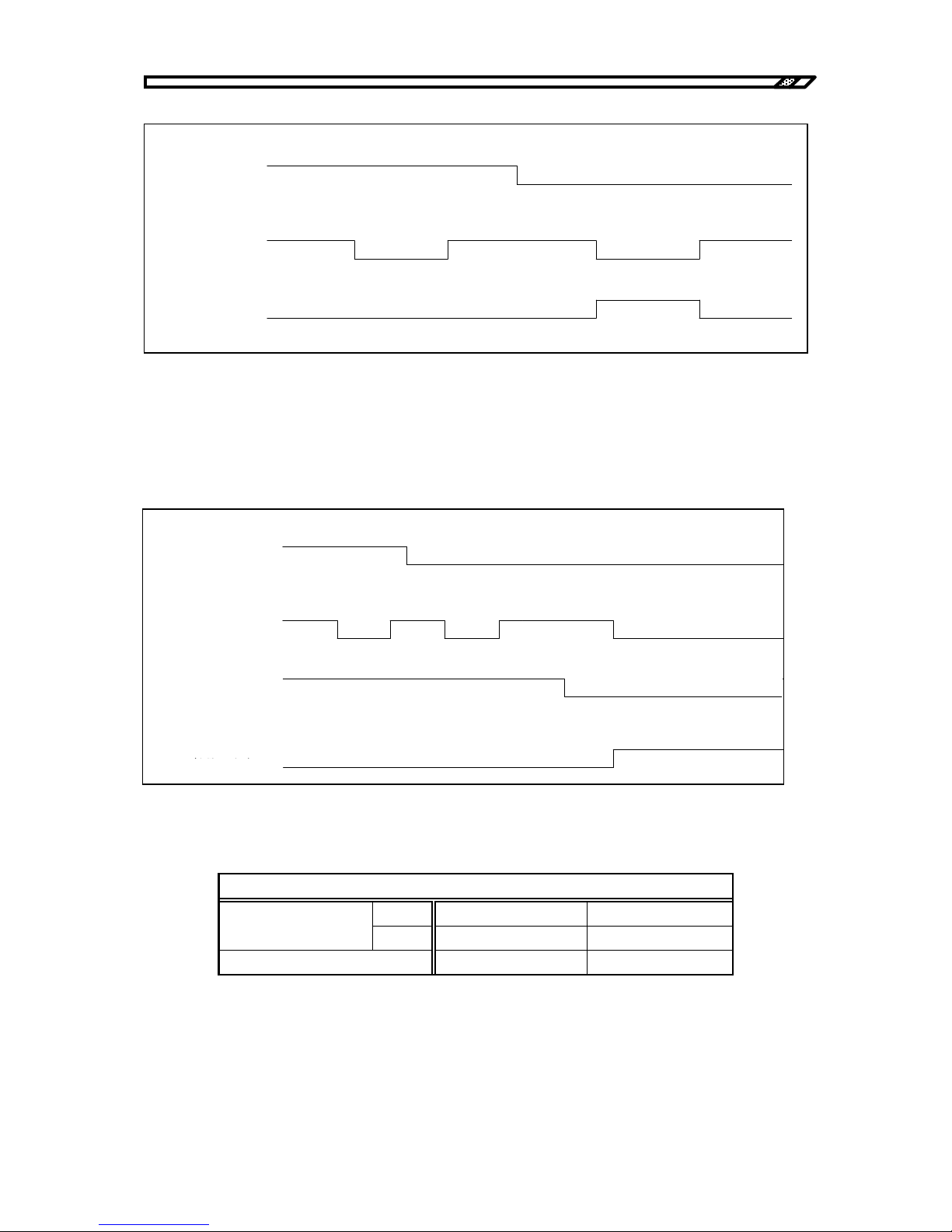
HIGH VOLTAGE POWER SUPPLY ON/OFF
HIGH VOLTAGE POWER SUPPLY ON/OFF controls ON/OFF of the internal DC high voltage
power supply.
When the HIGH VOLTAGE POWER SUPPLY ON/OFF switch on the front panel is ON and the
HIGH VOLTAGE POWER SUPPLY ON/OFF signal on the back panel is ON, the internal high
voltage DC power supply is ON.
Table3-1. Logic of HIGH VOLTAGE POWER SUPPLY ON/OFF
HIGH VOLTAGE POWER SUPPLY ON/OFF signal in remote control operation
Front panel switch OFF ON
TTL
High
(Approx. 5 V)
Low
(Approx. 0V)
High
(Approx. 5 V)
Low
(Approx. 0 V)
Back panel control
signal
Contact Open Close Open Close
Status of internal high voltage
DC power supply
OFF ON
For HIGH VOLTAGE POWER SUPPLY ON/OFF, the control with external signal is always effective
regardless of "REMOTE" or "LOCAL" settings on the front panel switch.
Therefore, when external control is not used, be sure to short-circuit the control input terminal at the
back with an accompanying shorting plug.
If shorting is not performed, the internal high voltage DC power supply is not ON although HIGH
VOLTAGE POWER SUPPLY ON/OFF switch on the panel is "ON".
+5 V +5 V
0. 0047µF
470
10k
74 HC14
470
Page 46
3.3 Monitor and control signal system
HVA4321
3-14
Figure3-20. Remote control of HIGH VOLTAGE POWER SUPPLY ON/OFF
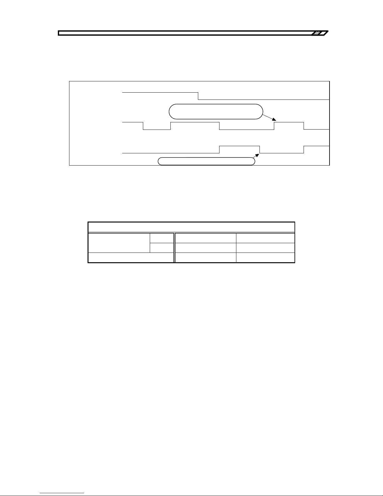
ON/OFF of signal system
Each signal of INT DC BIAS ON/OFF, EXT DC BIAS ON/OFF and OSC INPUT ON/OFF can be
individually controlled for ON/OFF. To give a signal output from the output terminal, both the desired
signal ON/OFF and SIGNAL ON/OFF must be ON.
Figure3-21. Remote control of signal system ON/OFF
Table3-2. Logic of signal system ON/OFF signal
ON/OFF signal of signal system in remote control operation
TTL High(Approx. 5V) Low(Approx. 0V)
Back panel control
signal
Contact Open Close
Signal status OFF ON
OFF
ON
Lo wHigh Low High
オフ状態 オン状態 オフ状態
High
ロックされている状態
ロックが解除されている状態
正面パネル
HI G H VOLT A GE
ON/OFF
スイッチ
背面パネル
ON/OFF
信号
内部高電圧
POWER SUPPLY
HI G H VOLT A GE
POWER SUPPLY
直流電源の状態
Front panel
HIGH VOLTAGE
POWER SUPPLY
ON/OFF switch
Back panel HIGH
VOLTAGE POWER
SUPPLY ON/OFF
signal
Internal high voltage
DC power
supply
status
Locked status Unlocked status
OFF status
ON status
OFF status
オフ状態
オン状態
正面パネル
RE MOTE/LOCAL
スイッチ
背面パネル
SI GNAL ON/OFF
信号
LOCAL REMOTE
ONOF F
ON
OF F
非出力
出力
信号の出力
各信号の
ON/OFF
信号
ON
OFF
Front panel
REMOTE/LOCAL
switch
ON/OFF signal of each
signal
Back panel SIGNAL
ON/OFF signal
No output
Output
Signal output
ON
OFF
Page 47
3.3 Monitor and control signal system
HVA4321
3-15
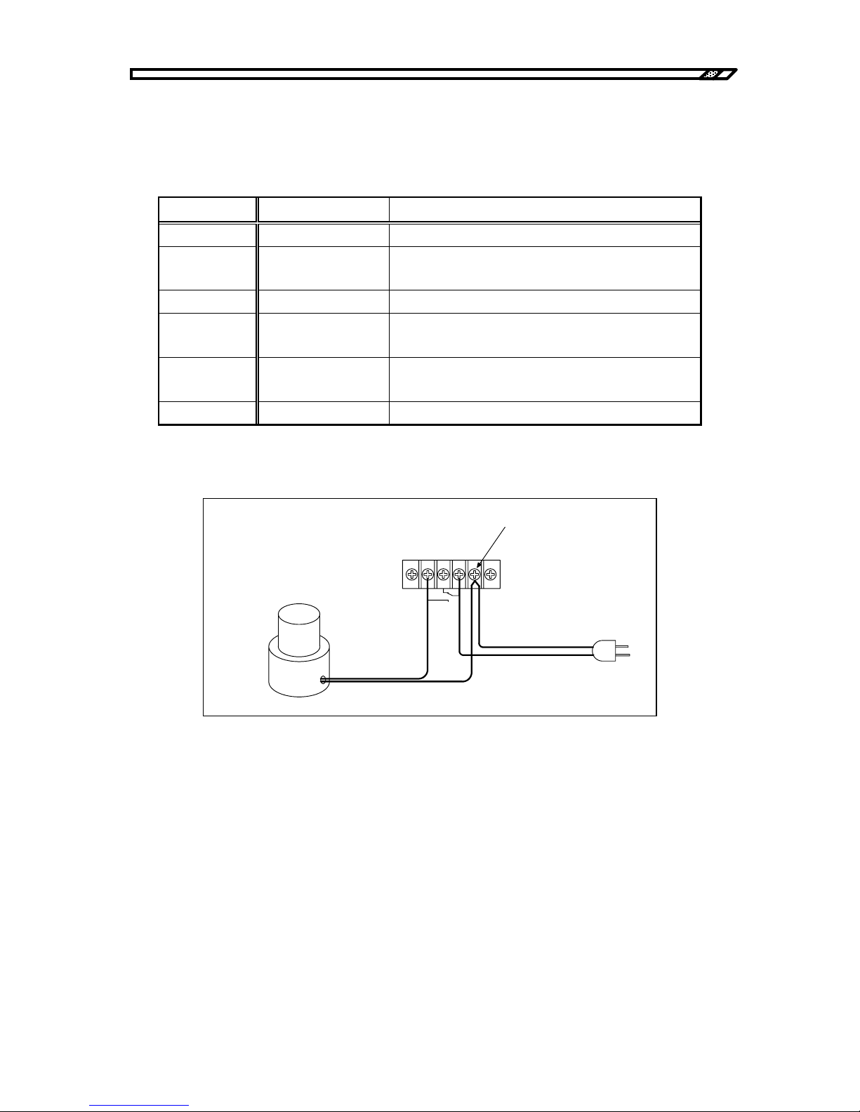
SIGNAL ON/OFF
SIGNAL ON/OFF controls a batch ON/OFF operation for input signals with external signal.
When SIGNAL is ON and ON becomes OFF for some reason, turn the control signal OFF once and
turn it ON again. Otherwise, SIGNAL is not ON.
Figure3-22. Remote control of signal ON/OFF
Table3-3. Logic of SIGNAL ON/OFF signal
SIGNAL ON/OFF signal in remote control operation
TTL High(Positive logic) Low(Positive logic)
Back panel control
signal
Contact Open Close
Signal status OFF ON
オフ状態
オン状態
オフ状態
正面パネル
RE MOTE/LOCAL
スイッチ
背面パネル
SI GNAL ON/OFF
信号
出力の状態
LOCAL REMOTE
ONOFF
ON
OF F
オン状態
ONOFF
(1)
過電流などで出力がオフすると、
(2)
出力オン指令中でも
一度オフにしないと再度オンしない。
Front panel
REMOTE/LOCAL
switch
Back panel SIGNAL
ON/OFF signal
Output status
OFF status
ON status
OFF status
ON status ON status
(2) It must be turned OFF once and ON again
when the output ON command is given
.
(1)
When the output is OFF due to over-current
Page 48
3.3 Monitor and control signal system
HVA4321
3-16
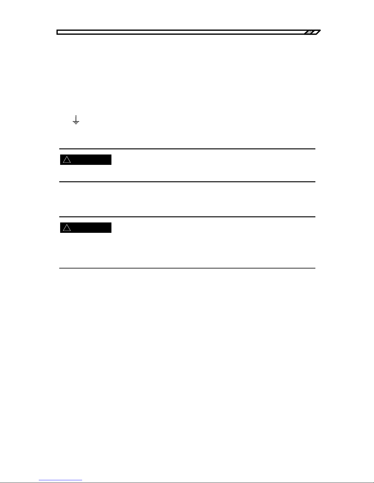
SIGNAL ON/OFF STATUS
It is the terminal to give contact signal output linked to SIGNAL ON/OFF status.
Table3-4. Status contact output signal
Terminal signal Signal name Explanation
-- ----
Terminal for fixing. Do not use it.
2 Not connected Not connected to any line. It can used as a relay
terminal.
3 COM Common terminal for contact output.
4 NC When SIGNAL is OFF, it is connected to the COM
terminal.
5 NO When SIGNAL is ON, it is connected to the COM
terminal.
-- ----
Terminal for fixing. Do not use it.
Figure3-23. Example of status contact output
SIGNALON/OFF STATUS
AC 250V 3A MAX
DC 30V 3A MAX
2345
2
番端子は中継端子として使用可能
SI GNAL ON
に点灯する表示灯など
AC1000 V
へ
No. 2 terminal can be used as a relay terminal.
Indicators that light for SIGNAL ON
(
Activated with AC100V
)
To AC100V
Page 49
3.4 Power supply items
HVA4321
3-17
!
!
3.4 Power supply items
POWER
It is the power switch of the unit.
LINE
It is connected to single phase AC100V.
Be sure to connect it to the outlet with ground with an accompanying 3 pin power cable.
It is terminal for grounding of casing. If grounding is not available with a power cable, ground this
terminal with a wire of 2 mm
2
or more.
Be sure to ground this unit for safety. Otherwise, a serious accident such as electric shock may occur.
FUSE
Use a 10A/250V fuse with time lag.
When a fuse is replaced, be sure to disconnect the power cable from the outlet. Replace it with the same
standard one.
For this product, the time lag type fuse with the rating of 10A/250V and φ2 x 20 mm is used.
WARNING
WARNING
Page 50

Page 51
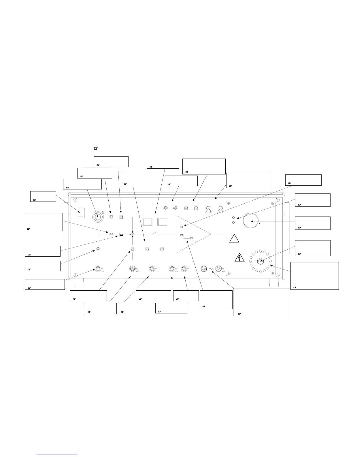
3.5 Nomenclature
HVA4321
3-18
3.5 Nomenclature
3.5.1 Front panel
Page number of detailed explanation is shown after
.
●
ON/OFF
外部発振器からの信号を
使用するときオンにします。
&
(3.1.3)
TRIP
POWER
DC BIAS
0-10
V
+
-
ON
OFF
SIGNAL
OFF
ON
VOLTAGE(kV)
-5
-10
MAX
5
10
MAX
LI MIT
DC CURRENT(mA)
0
10
RESPONSE
CV CC
HIGHVOLTAGE
POWER SUPPL Y
PUSHOFF
ON
OFF
OVERLOAD
CV
1kV/1V
CC
1mA/1V
DC BIAS
CV
CC
CURRENT
SELECT
LOAD
TOTAL
ON/OFF
CONTROL
REMOTE
LOCAL
ON
OFF
ON
OFF
INVERT
NORMAL
GAIN
OSC
INPUT
±
10V MAX
Zi n 1 0k
Ω
EXT DC BIAS
OUTPUT
TTL(Lo:ON)
Zout 10k
Ω
SIGNAL ON/ OFF STAT US
OUTPUT
MONITOR
1V/1kV
Zout 5 0
Ω
VOLTAGE
CURRENT
LOAD
CURRENT
TOTAL
CURRENT
OUTPUT Lo
危険防止のた め 、 出力の配線を 変更する と き は必ず
上のス イ ッ チ を 押して H V 電源を OF F し て く だ さ い 。
DAN GE R
OUTPUT Hi
PULL ON
危険防止のため、
出力中は出力ケ ーブ ル に
絶対に触れ ない でく ださ い。
±
10kV MAX
±
10mA MAX
±
10V MAX
Zin 10k
Ω
1V/10mA
Zout 5 0
Ω
I
O
LI MITER
!
●
ON/OFF
内部直流バイアス信号を使用するとき
オンにします。
&
(3.1.1)
●
SIGNAL ON/OFF
増幅部に入力される信号の
オン・オフスイッチです。
&
(3.1.4)
●
ON/OFF CONTROL
SIGNAL ON/OFF や各信号のON/OFFを
LOCAL パネル操作
REMOTE 外部信号操作
に切り替えるスイッチです。
&
(3.3.2)
●
SI G NA L O N/ OFF STAT US OUTP UT
SIGNALのオンオフ状態を示す信号を
出力します
&
(3.3.2)
●
MONITORVOLTAGE
出力電圧モニタ用の
BNC接栓です。
&
(3.3.1)
●
MONITOR CURRENT
出力電流モニタ用の
BNC接栓です。
&
(3.3.1)
●
OUTPUT L o
本器の高圧出力の帰還側の端子です。
TOTAL
この端子を使用した場合、浮遊容量などへの漏れ電流と
負荷に流れる電流を制御します。
LOAD
この端子を使用した場合、浮遊容量への漏れ電流を無視して
負荷に流れる電流を制御します。
&
(3.2.3)
●出力警告表示灯
高電圧出力中は表示灯が点灯しながら
回転します。
出力電圧が約
4. 9
kV以下で橙色、約
4. 9
kV以上
で赤色に点灯します。
また電圧レベルにより回転速度が変化し、
高電圧ほど高速に回転します。
&
(3.2.3)
●
DC CURRENT LI MITER
最大出力電流の設定を行います。
LIMIT 制限のみ
TRIP 設定値を超えると停止
&
(3.2.2)
●
VOLTAGE LIMITER
最大出力電圧の設定を行います。
&
(3.2.2)
●
POWER
本器の電源スイッチです。
&
(3.4)
●
O
N/OFF
外部からの直流バイアスを使用するとき
オンにします。
&
(3.1.2)
●
EXT DC BIASINPUT
直流バイアスを外部から入力する
BNC
接栓です。
&
(3.1.2)
●
GAIN
SIGNAL INPUTに入力された
信号の利得を調整します。
&
(3.1.3)
●
NORMAL/INVERT
入出力間の極性を設定します。
NORMAL:入出力同相
INVERT :入出力逆相
&
(3.1.3)
●
DC BIAS
つまみ
内部直流バイアス用内部信号源の
レベルを設定します。
&
(3.1.1)
●+/-
内部直流バイアス用信号源の
極性を設定します。
&
(3.1.1)
●
SI G NA L I NP UT
外部発振器からの信号を
入力する
BNC
接栓です。
&
(3.1.3)
●
CURRENT SELECT
OUTPUT Lo端子の接続先に
合わせて切り替えます。
&
(3.2.3)
●
OUTPUT Hi
高圧側の出力端子です。
附属の専用高圧ケーブルを繋ぎます。
&
(3.2.3)
●
RESPONSE
ステップ応答波形の微調を行います。
CV 定電圧モードで使用します。
CC 定電流モードで使用します。
&
(3.2.2)
●
HI GH VOLTAGEOUTPUT ON/OFF
内部高電圧直流電源のオン・オフ
スイッチです。
&
(3.2.3)
●
ON/OFF
内部高電圧直流電源のオンオフ
状態を表示します。
&
(3.2.3)
●
CV/CC DC BI AS CV/CC
動作モードの設定を行います。
CV 定電圧モード
CC 定電流モード
CV:直流はCVモード
CC:直流もCCモード
&
(3.2.1)
●
OVERLOAD
過負荷状態やリミッタが動作
しているときに点灯します。
&
(3.2.1)
33
Ω
●ON/OFF
ON when the internal DC
bias signal is used.
(3.1.1
)
●+/-
Sets polarity of the internal
DC bias signal source.
(3.1.1)
●DC bias knob
Sets the level of the internal
signal for the internal DC bias.
(3.1.1)
●POWER
Power switch of this
unit.
(3.1.4)
●NORMAL/INVERT
Sets polarity of input/output.
NORMAL:
Same phase for input/output
INVERT:
Inverted phase for input/output
(3.1.3)
●ON/OFF
ON when the signal from an
external oscillator is used.
(3.1.3)
●GAIN
Adjusts gain of the signal to
SIGNAL INPUT.
(3.1.3)
●SIGNAL INPUT
BNC connector to give signal
input from an external oscillator.
(3.1.3)
●ON/OFF
ON when the external DC
bias is used.
(3.1.2)
●EXT DC BIAS INPUT
BNC connector to give
external DC bias input.
(3.1.2)
●
SIGNAL ON/OFF STATUS OUTPUT
Gives signal that indicates
SIGNAL ON/OFF status.
(3.3.2)
●MONITOR VOLTAGE
BNC connector for
output voltage monitor.
(
3.3.1
)
●CURRENT SELECT
Selects current to the OUTPUT
Lo terminal connection.
(3.2.3
)
●
MONITOR CURRENT
BNC connector for
output current monitor.
(
3.3.1
)
●CV/CC DC BIAS CV/CC
Sets the operation mode.
CV: Constant voltage mode
CC: Constant current mode
CV: CV mode for DC
CC: CC mode for DC
(3.2.1)
●
Output Lo
Return terminal for high voltage output of this unit.
TOTAL
When this terminal is used, total current of the
leak current to stray capacitance and the
current to load is controlled.
LOAD
When this terminal is used, the current to load is
controlled ignoring the leak current to stray
capacitance.
(3.2.3)
●Output warning indicator
The indicator lights and rotates during
high voltage output.
It lights in orange when the output
voltage is approx. 4.9 kV or less and red
when the voltage is approx. 4.9 kV or
more.
The rotation speed changes depending
on the voltage level. The higher the
voltage is, the faster the rotation is.
(3.2.3)
●OUTPUT Hi
Output terminal for high
voltage.
Connect the accompanying
special high voltage cable.
(3.2.3)
●
HIGH VOLTAGE OUTPUT ON/OFF
ON/OFF switch of the
internal high voltage DC
power supply.
(3.2.3)
●ON/OFF
Indicates ON/OFF status of
the internal high voltage DC
power supply.
(3.2.3)
●OVERLOAD
Lights for overload status or
when the limiter is activated.
(3.2.1)
●RESPONSE
Makes fine adjustment of step
response waveform.
CV: Used in constant voltage mode.
CC: Used in constant current mode.
(
3.2.2
)
●DC CURRENT LIMITER
Sets the maximum output current.
LIMIT: Only limiting.
TRIP: Stops operation when
exceeding the set value.
(3.2.2)
●SIGNAL ON/OFF
ON/OFF switch for input
signal to the amplifier.
(
3.1.4
)
●VOLTAGE LIMITER
Sets the maximum output
voltage.
(
3.2.2
)
●ON/OFF CONTROL
Switch to change SIGNAL ON/OFF or
ON/OFF of each signal to:
LOCAL: Panel operation
REMOTE: External signal operation
(3.3.2)
Page 52

Page 53
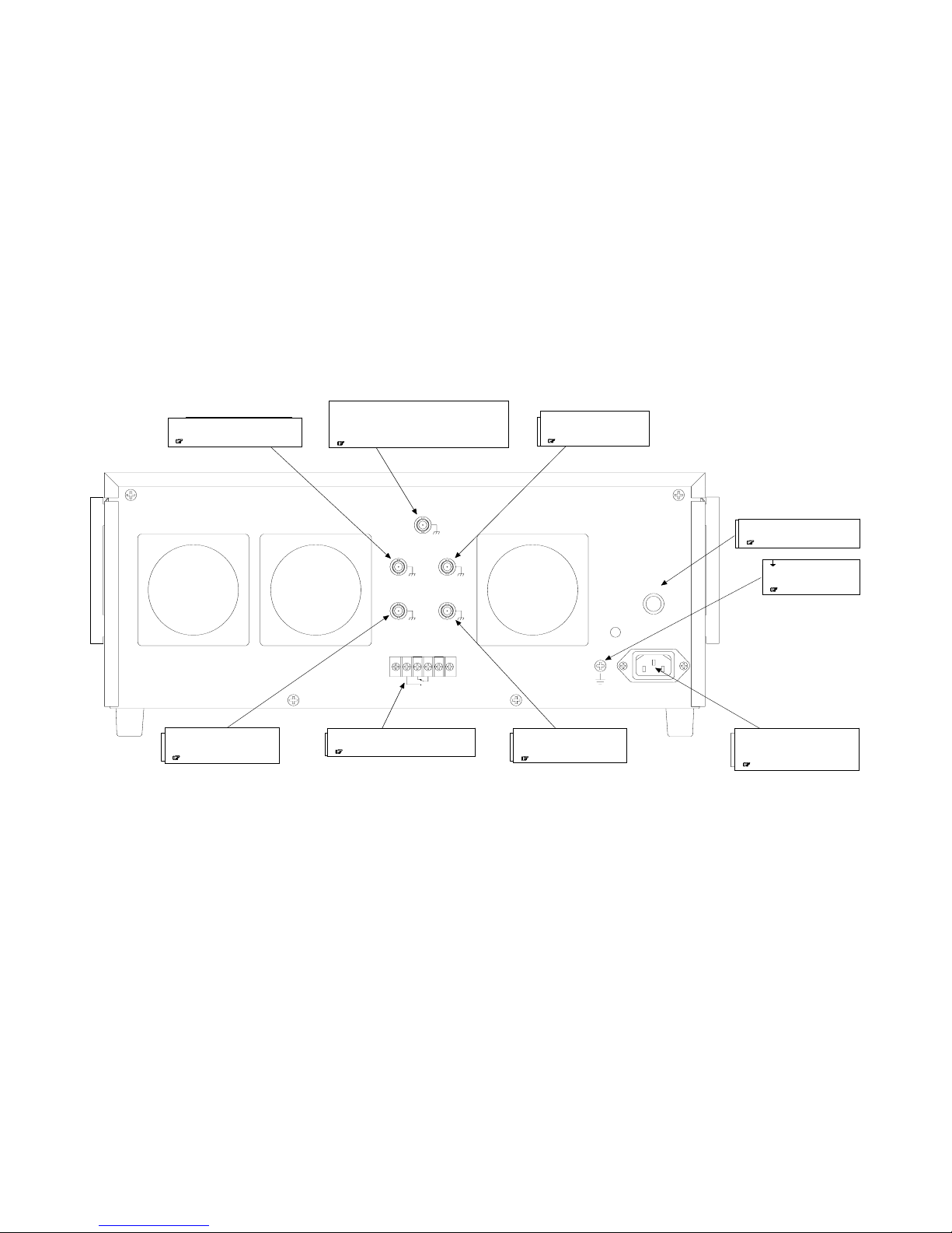
3.5 Nomenclature
HVA4321
3-19
3.5.2 Rear panel
INTDC BIASON/OFFSIGNAL ON/OFF
OSCI NPUT ON/OFF EXTDCBIASON/OFF
HIGHVOLTAGE
POWERSUPPLYON/OFF
TTL(Lo:ON)TTL(Lo:ON)
TTL(Lo:ON)TTL(Lo:ON)
TTL(Hi:OFF)
REMOTE CONTROL I NPUT
SIGNAL ON/ OFF STATUS
AC250V 3A MAX
DC 30V 3 A MAX
2
~
LI NE
100V
T
10A/
250V
50Hz/60Hz 800VA MAX
●
SI G NA L O N/OFF
リモート操作時に増幅部へ入力する信号の
オン・オフ制御信号を入力します。
&
(3.3.2
)
●
HIGHVOLTGAEPOWERSUPPLYON/OFF
内部高電圧直流電源のオン・オフを外部信号で制御するときの
オン・オフ信号を入力します。
外部信号で制御しないときは附属のショートプラグにて短絡して
おきます。
&
(3.3.2)
●
INT DCBIASON/OFF
リモート操作時に内部直流バイアス信号の
オン・オフ制御信号を入力します。
&
(3.3.2)
●
EXT DC BIASON/OFF
リモート操作時に外部直流バイアス信号の
オン・オフ制御信号を入力します。
&
(3.3.2)
●
SIGNALON/ OFFST ATUS
SIGNALオン・オフの状態に連動した接点信号を出力します。
&
(3.3.2)
●
FUSEHOLDER
ヒューズホルダです。
本器ではAC250V 10Aのヒューズを使用します。
&
(3.4)
●
LI NE
電源ラインを接続するためのインレットです。
安全のため必ず附属の3pin電源コードで接地付き
コンセントに接続してください。
&
(3.4)
●
OSC I NP UT ON/OFF
リモート操作時に外部発振器の入力信号の
オン・オフ制御信号を入力します。
&
(3.3.2)
●
電源コードで接地が取れないときに
使用する筐体接地端子です。
&
(3.4)
345
●SIGNAL ON/OFF
Gives ON/OFF control signal input to the
amplifier for remote control operation.
(3.3.2)
●INT DC BIAS ON/OFF
Gives ON/OFF control signal of
the internal DC bias signal for
remote control operation.
(3.3.2)
●FUSE HOLDER
Fuse holder.
This unit uses a AC250V 10A fuse.
(3.4)
●LINE
Inlet to connect the power cable.
Be sure to connect the accompanying
3 pin power cable to the outlet with
ground for safety.
(3.4)
●
Casing ground terminal when
grounding is not available
with a power cable.
(3.4)
●EXT DC BIAS ON/OFF
Gives ON/OFF control signal of
external DC bias signal for remote
control operation.
(
3.3.2
)
●SIGNAL ON/OFF STATUS
Gives contact signal output linked to SIGNAL
ON/OFF status.
(3.3.2)
●OSC INPUT ON/OFF
Gives ON/OFF control signal input
of the external oscillator for remote
control operation.
(3.3.2)
●HIGH VOLTAGE POWER SUPPLY ON/OFF
Gives the ON/OFF signal for control of the internal high
voltage DC power supply ON/OFF with an external
signal.
Use the accompanying shorting plug for short-circuit
when it is not controlled with an external signal.
(3.3.2)
Page 54

Page 55
4. Operation method
4.1 Operation example in constant voltage mode
・・・・・・・・・
4-1
4.1.1 Panel setting
・・・・・・・・・・・・・・・・・・・・・・・・・・・・・・・・・
4-3
4.1.2 Connection of signal source and
connection of load
・・・・・・・・・・・・・・・・・・・・・・・・・・・・
4-6
4.1.3 Power supply and internal high voltage
DC power supply
・・・・・・・・・・・・・・・・・・・・・・・・・・・・・
4-9
4.1.4 Signal output and adjustment
・・・・・・・・・・・・・・・・・・
4-11
4.1.5 Signal OFF
・・・・・・・・・・・・・・・・・・・・・・・・・・・・・・・・・
4-13
4.2 Operation example in constant current mode (total)・4-14
4.2.1 Panel setting
・・・・・・・・・・・・・・・・・・・・・・・・・・・・・・・
4-16
4.2.2 Connection of signal source and
connection of load
・・・・・・・・・・・・・・・・・・・・・・・・・・
4-19
4.2.3 Power supply and internal high voltage
DC power supply
・・・・・・・・・・・・・・・・・・・・・・・・・・・
4-22
4.2.4 Signal output and adjustment
・・・・・・・・・・・・・・・・・
4-24
4.2.5 Signal OFF
・・・・・・・・・・・・・・・・・・・・・・・・・・・・・・・・・
4-26
4.3 Operation example in constant current mode (load)・4-27
4.3.1 Panel setting
・・・・・・・・・・・・・・・・・・・・・・・・・・・・・・・
4-29
4.3.2 Connection of signal source and
connection of load
・・・・・・・・・・・・・・・・・・・・・・・・・・
4-32
4.3.3 Power supply and internal high voltage
DC power supply
・・・・・・・・・・・・・・・・・・・・・・・・・・・
4-35
4.3.4 Signal output and adjustment
・・・・・・・・・・・・・・・・・
4-37
4.3.5 Signal OFF
・・・・・・・・・・・・・・・・・・・・・・・・・・・・・・・・・
4-39
4.4 Operation example in constant current + constant
voltage mode
・・・・・・・・・・・・・・・・・・・・・・・・・・・・・・・・・・・
4-40
4.4.1 Panel setting
・・・・・・・・・・・・・・・・・・・・・・・・・・・・・・・
4-42
4.4.2 Connection of signal source and connection
of load
・・・・・・・・・・・・・・・・・・・・・・・・・・・・・・・・・・・・・
4-45
4.4.3 Power supply and internal high voltage DC
power supply
・・・・・・・・・・・・・・・・・・・・・・・・・・・・・・・
4-48
4.4.4 Signal output and adjustment
・・・・・・・・・・・・・・・・・
4-50
4.4.5 Signal OFF
・・・・・・・・・・・・・・・・・・・・・・・・・・・・・・・・・
4-52
4.5 Change of load and power OFF
・・・・・・・・・・・・・・・・・・・
4-53
4.5.1 Change of load
・・・・・・・・・・・・・・・・・・・・・・・・・・・・・
4-53
4.5.2 Power supply OFF
・・・・・・・・・・・・・・・・・・・・・・・・・・
4-56
4.6 Remote control
・・・・・・・・・・・・・・・・・・・・・・・・・・・・・・・・・
4-57
4.6.1 Remote control
・・・・・・・・・・・・・・・・・・・・・・・・・・・・・
4-57
4.6.2 Panel setting for use of remote control
・・・・・・・・・
4-58
Page 56

Page 57
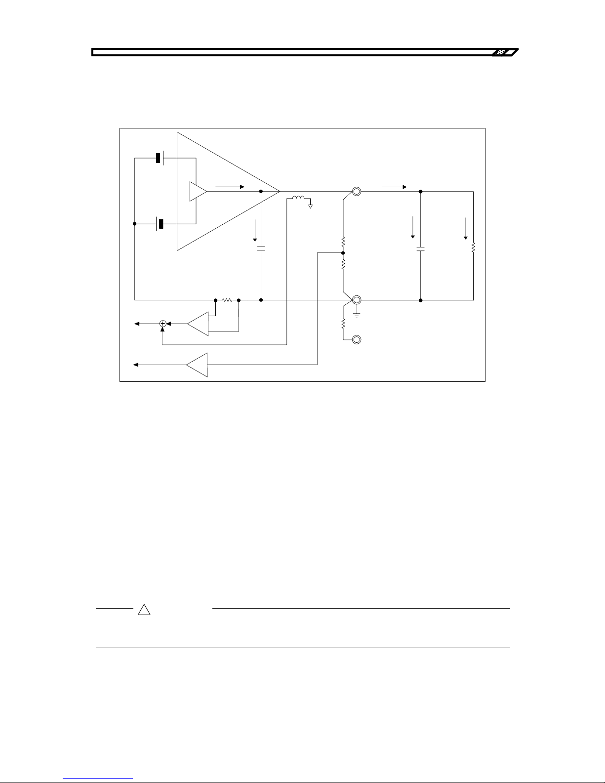
4.1 Operation example in constant voltage mode
HVA4321
4-1
4.1 Operation example in constant voltage mode
This section describes operation example for use of this unit in constant voltage mode.
In constant voltage mode, the output voltage changes according to the input signal.
Figure4-1. Constant voltage mode (total mode)
lamp :Output current of high voltage amplifier
lint :Leak current with internal capacity
lout :Output current
lstr :Leak current with wire capacity
lload :Load current
lac, ldc :DC and AC of detected current
In total mode, from output current lout, DC is detected with current detection resistance and AC is
detected with current transformer CT. Total output of leak current lstr with wire capacity and load current
lload is given to the current monitor.
(Leak current lint (AC) with stray capacity in the amplifier runs through the current detection resistance,
but only DC is detected here. The monitor is hardly affected.)
Effect of stray capacitance of the cable is found only for AC signal output. Effect of stray signal is not
found for DC signal. Therefore, use the DC signal in total mode.
!
CAUTION
内部容量
出力端子
配線の容量
負荷抵抗
電流検出抵抗
電流検出抵抗
(トータル用)
(ロード用)
電流モニタ
OUTPUT Hi
OUTPUT Lo
TOTAL
LOAD
Iout
Ii nt
Istr
Il oad
Iamp
Iac
Idc
CT
電圧モニタ
Output terminal
Load
resistance
Wire capacit
y
Internal capacit
y
Current detection
resistance
(
for total
)
Current monitor
Voltage monitor
Current detection resistance
(for load)
Page 58
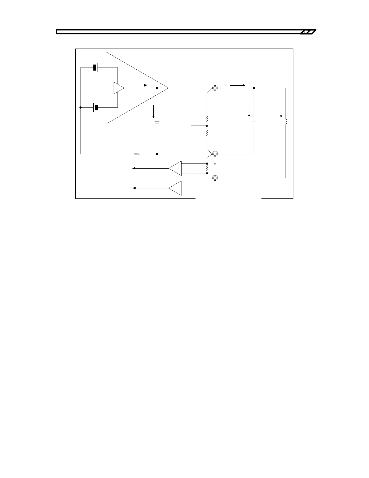
4.1 Operation example in constant voltage mode
HVA4321
4-2
Figure4-2. Constant voltage mode (load mode)
lamp : Output current of high voltage amplifier
lint : Leak current with internal capacity
lout : Output current
lstr : Leak current with wire capacity
lload : Load current
lac, ldc : DC and AC of detected current
In load mode, only load current is directly detected. The current monitor can monitor load current only.
In load mode of constant voltage mode:
○Advantage
・Only load current can be monitored.
○Disadvantage
・One end of load cannot be directly grounded. There is a current detection resistance
(33Ω) between load end and ground.
・The voltage of output current x current detection resistance (33Ω) for set output voltage is an
error in load. (When the load current is 10 mA, the error is 330 mV.)
内部容量
出力端子
配線の容量
負荷抵抗
電流検出抵抗
電流検出抵抗
(トータル用)
(ロード用)
電流モニタ
OUTPUT Hi
OUTPUT Lo
TOTAL
LOAD
Iout
Ii nt
Istr
Il oad
Iamp
Idc+Iac
電圧モニタ
Output terminal
Load
resistance
Wire capacit
y
Internal capacit
y
Current detection
resistance
(
for total
)
Current monitor
Voltage monitor
Current detection resistance
(for load)
Page 59
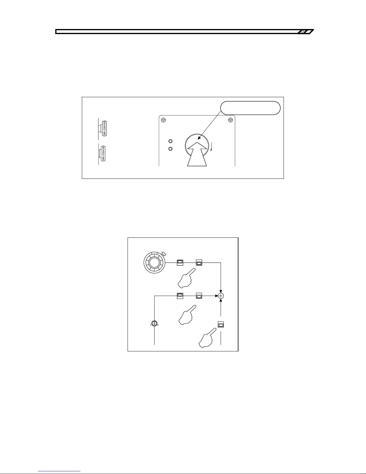
4.1 Operation example in constant voltage mode
HVA4321
4-3
4.1.1 Panel setting
a) Internal high voltage DC power OFF
When the HIGH VOLTAGE POWER SUPPLY switch is not OFF, press the button until a "click" sound is
heard. When a click sound is heard, the switch is locked in OFF status. The internal high voltage DC
power supply is always OFF.
Figure4-3. Internal high voltage DC power OFF
b) Signal system OFF
Turn the internal DC bias knob to the leftmost position to minimize the value. Turn OFF the switches of
DC BIAS, OSC INPUT and EXT DC BIAS INPUT.
Figure4-4. Switch settings
DC BIAS
0-10
kV
+
-
ON
OFF
ON
OFF
ON
OFF
INVERT
NORMAL
GAIN
HIGHVOLTAGE
POWER SUPPLY
PUSH OFF
ON
OFF
危険防止のた め 、 出力の配線を 変更する と き は必ず
上のス イ ッ チを 押し て H V 電源を O F F し て く だ さ い。
PULL ON
カチッと音がするまで
押し ます。
ロックされた状態
オフ
オン
側面より
From side
ON
OFF
Locked status
Press the switch until a click
sound is heard.
Page 60
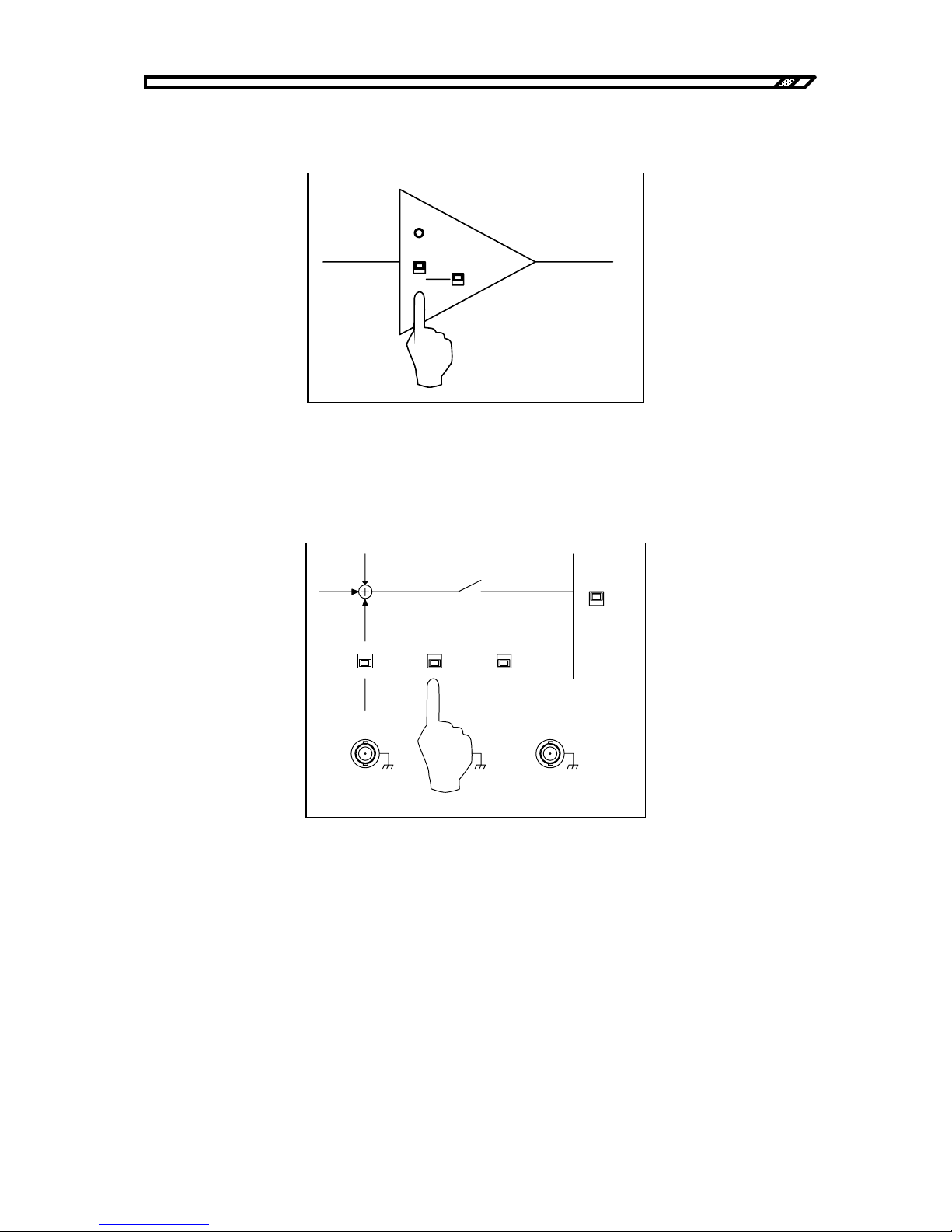
4.1 Operation example in constant voltage mode
HVA4321
4-4
c) Output mode settings
Set the output mode switch to CV. In constant voltage mode, the DC bias setting is invalid.
Figure4-5. Output mode settings
d) Remote/local settings
To operate this unit from the panel, set the ON/OFF CONTROL switch to LOCAL.Refer to "4.6 Remote
control operation" for remote control operation.
Figure4-6. Local settings
OVERLOAD
CV
1kV/1V
CC
1mA/1V
DC BIAS
CV
CC
CV
1kV/1V
CC
1mA/1V
CURRENT
SELECT
LOAD
TOTAL
ON/OFF
CONTROL
REMOTE
LOCAL
ON
OFF
EXT DC BIAS
OUTPUT
TTL(Lo: ON)
Zout 10k
Ω
SIGNAL ON/ OFF STAT US
OUTPUT
MONITOR
1V/1kV
Zout 50
Ω
VOLTAGE
CURRENT
±
10V MAX
Zi n 10 k
Ω
1V/1mA
Zout 50
Ω
Page 61
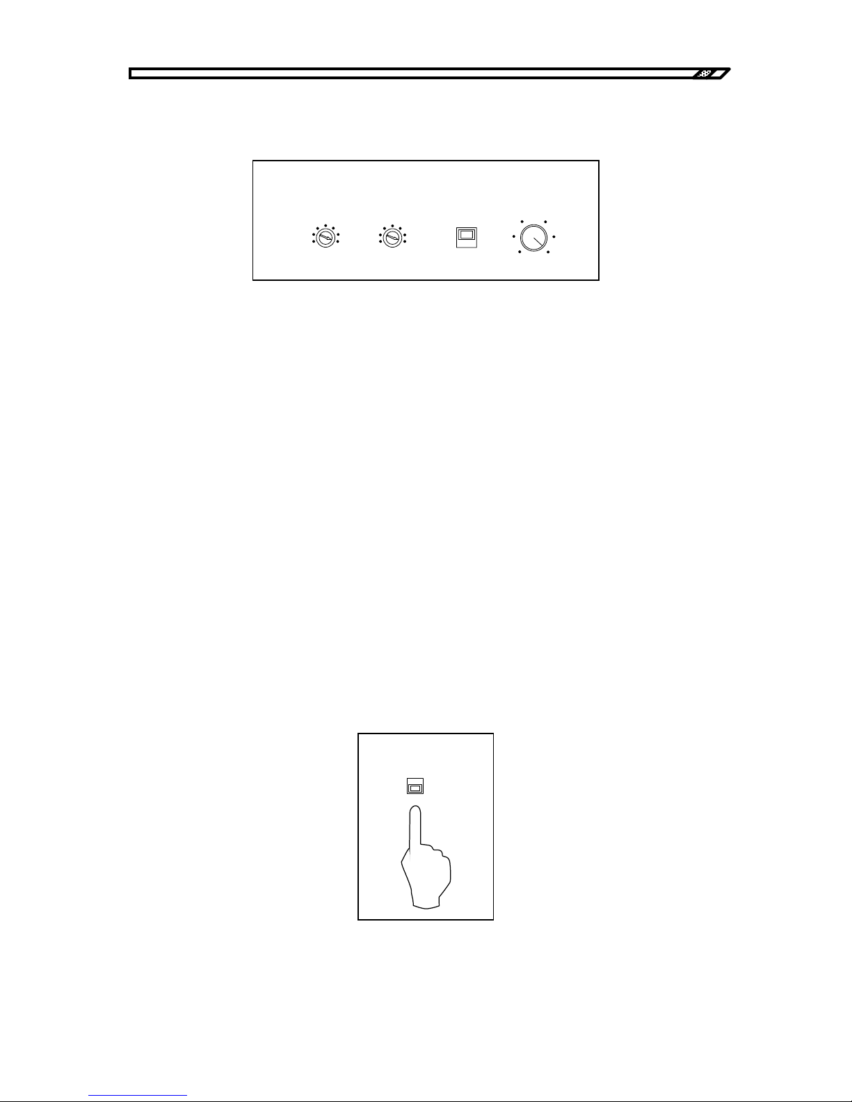
4.1 Operation example in constant voltage mode
HVA4321
4-5
e) Output limiter settings
To limit the output voltage and output current, set the limiter level as required.
Figure4-7. Limiter settings
Voltage limiter
The voltage limiter function can limit the maximum value of the output voltage independently for
positive and negative values in the range from ±5 kV to ±10 kV. For example, the output is sufficient
up to ±8 kV, set the VOLTAGE LIMITER to 8 kV and -8 kV.
When voltage limitation is not required, set it to MAX.
Current limiter
The current limiter function can limit the average value of the output current in the range from 0 mA to
±10 mA. For example, to limit the output current up to 5 mA, set it to 5 mA.
When current limitation is not required, set it to 10 mA which is turned to the rightmost position.
LIMIT/TRIP
Set the protection mode for activation of the current limiter. When LIMIT is selected, current is limited
to the set current. When TRIP is selected, the input signal is immediately OFF for activation of the
current limiter circuit and the output is 0V.
Select either one as required.
f) Current monitor mode settings
In total mode, set it to TOTAL CURRENT and in load mode, set it to LOAD CURRENT.
Figure4-8. Current monitor mode settings
TRIP
VOLTAGE(kV)
-5
-10
MAX
5
10
MAX
LI MIT
DC CURRENT( mA)
0
10
LI MITER
CURRENT
SELECT
LOAD
TOTAL
Page 62
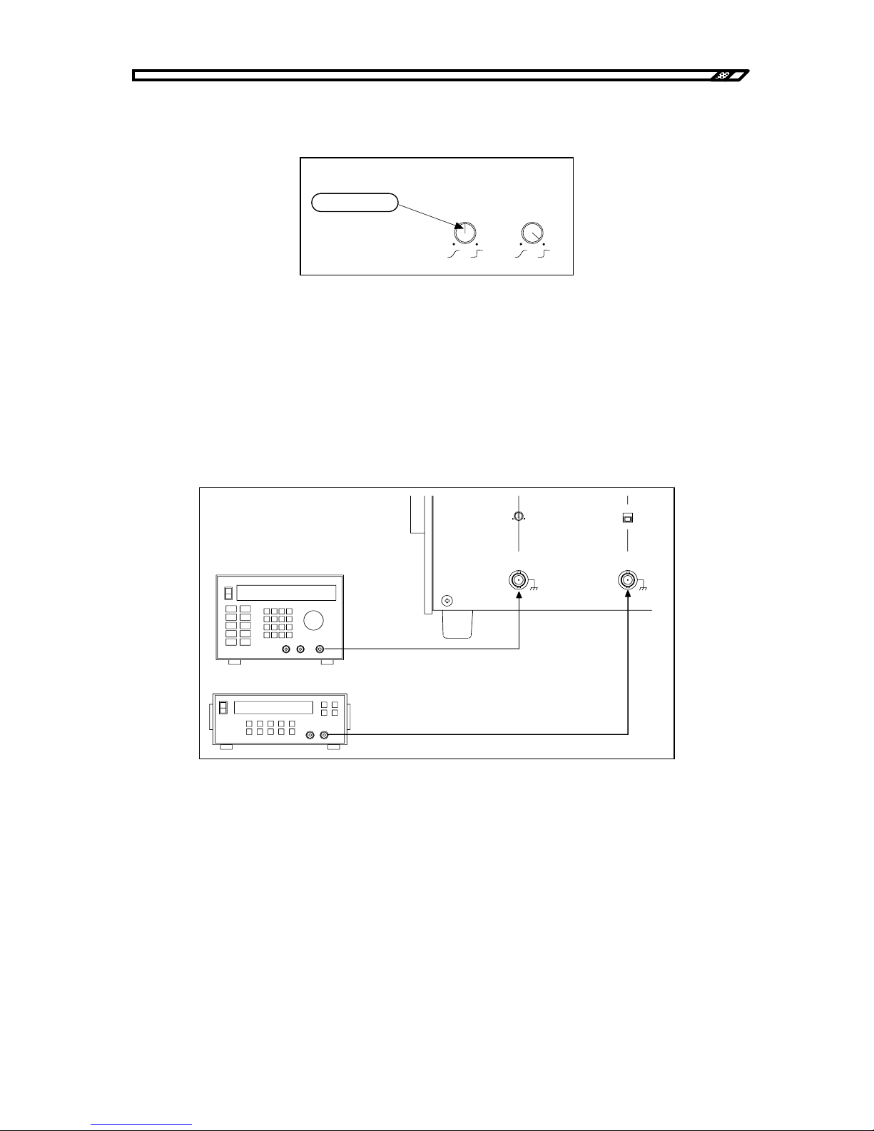
4.1 Operation example in constant voltage mode
HVA4321
4-6
g) RESPONSE knob settings
Set the CV RESPONSE knob to TOP.
Figure4-9. Response settings
4.1.2 Connection of signal source and connection of load
a) Connection of input signal source
Give the signal generator (e.g. oscillator) output to OSC INPUT. When applying the external DC bias,
give the DC signal source output to EXT DC BIAS INPUT.
The input voltage of the OSC INPUT terminal and the EXT DC BIAS INPUT terminal is maximum ±10V.
Figure4-10. Connection of external signal source signal
信号発生器
直流基準電源
ON
OFF
GAIN
OSC
INPUT
±
10V MAX
Zi n 1 0 k
Ω
EXT DC BIAS
OUTPUT
±
10V MAX
Zi n 1 0 k
Ω
Signal generator
DC standard power supply
RESPONSE
CV CC
真上にします。
Set it to TOP.
Page 63
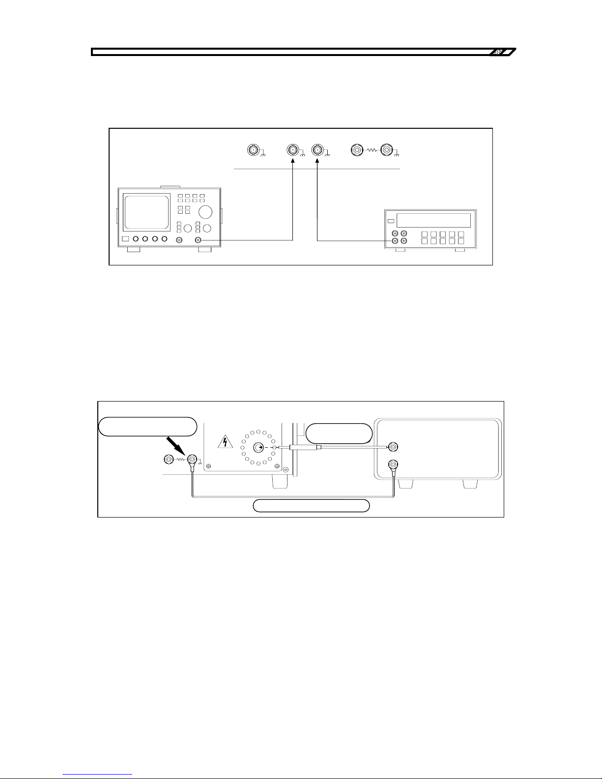
4.1 Operation example in constant voltage mode
HVA4321
4-7
b) Monitor signal output
Connect a measuring instrument such as oscilloscope or voltmeter to VOLTAGE MONITOR or
CURRENT MONITOR as required.
Figure4-11. Connection of monitor
c) Connection of load
Be sure to use the accompanying cable for the cable connected to Hi. To minimize effect from stray
capacitance, shorten the cable length as much as possible and keep it away from the floor or other devices.
Connect the output return wire to TOTAL CURRENT terminal in total mode.
Connect it to LOAD CURRENT in load mode.
Figure4-12. Connection of output cable
電圧計
SIGNAL ON/ OFF STATUS
OUTPUT
MONITOR
VOLTAGE
CURRENT
LOAD
CURRENT
TOTAL
CURRENT
OUTPUT Lo
オシロスコ ープ
Voltmeter
Oscilloscope
LOAD
CURRENT
TOTAL
CURRENT
OUTPUT Lo
±
10kV MAX
±
10 mA MAX
OUTPUT Hi
緩ま ないよ う にし っ かり と
締めて く だ さ い。
負荷
附属の高圧ケー ブル
附属のリ タ ーン ケーブ ル
Tighten it securely
Accompanying high
volta
g
e cable
A
ccompanying return cable
Load
Page 64
4.1 Operation example in constant voltage mode
HVA4321
4-8
!
Match the setting of the return terminal with that of the CURRENT SELECT switch. If it is different,
current cannot be monitored.
The TOTAL CURRENT terminal is connected to the casing.
Tighten the binding post terminal of OUTPUT Lo securely. If it is loose, electric shock may occur when
touching the load grounding or the return cable.
Check sometimes if it is not loose when the power is OFF and it is safe.
WARNING
!
CAUTION
Page 65
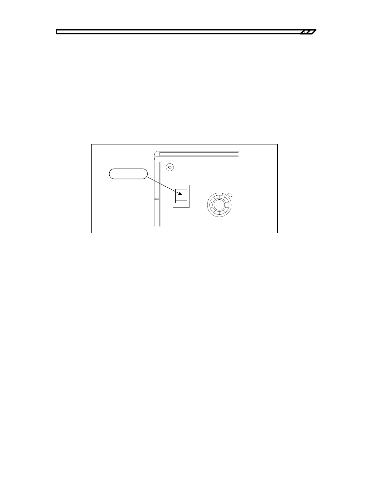
4.1 Operation example in constant voltage mode
HVA4321
4-9
4.1.3 Power supply and internal high voltage DC power supply
a) Power supply
Before supply of power, check again if the HIGH VOLTAGE POWER SUPPLY switch is OFF (button is
pressed). After checking connection to load, connection to the signal source and if the panel settings are
correct, turn ON the POWER switch of the unit.
When the power is ON, the fan at the back starts operation.
On the panel surface:
・The OFF lamp of the signal switch blinks.
・The OFF LED of the internal high voltage DC power supply lights.
Figure4-13. Power supply
b) Supply of high voltage DC power
Turn the HIGH VOLTAGE POWER SUPPLY switch to the right and unlock it. Turn ON the internal high
voltage power supply. The ON LED of the internal high voltage power supply lights. In several seconds,
the SIGNAL switch OFF lamp changes from blinking to lighting.
When the power is supplied, the internal high voltage DC power supply is always OFF regardless of
ON/OFF status of the HIGH VOLTAGE POWER SUPPLY switch. If this switch is ON, turn OFF once
and turn it ON again.
POWER
DC BIAS
0-10
V
I
O
オンにし ます。
Turn ON.
Page 66
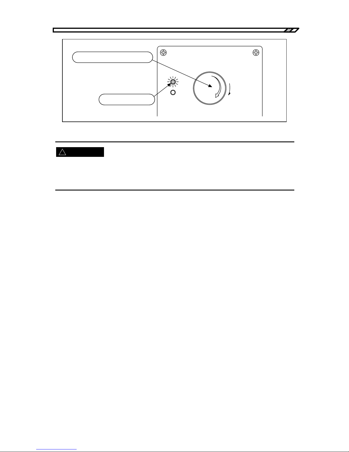
4.1 Operation example in constant voltage mode
HVA4321
4-10
!
Figure4-14. Internal high voltage DC power ON
After this operation, the internal high voltage DC power supply is ON. High voltage is generated inside the
unit.
Be careful not to touch the area like an output terminal to which high voltage is applied.
○When the SIGNAL OFF switch remains blinking.
When the SIGNAL OFF switch remains blinking after unlocking the HIGH VOLTAGE POWER
SUPPLY switch, check the following:
1) Is the shorting plug inserted into the HIGH VOLTAGE POWER SUPPLY ON/OFF terminal at the
back?
Action
Insert the shorting plug for operation in LOCAL mode.
2) Is the DC CURRENT value the minimum and is TRIP selected?
Action
Increase the current limit or select LIMIT.
3) Is temperature of exhaust air extremely high?
Action
Temperature in the casing may be too high. Leave the unit at a cool environment for dozens of
minutes. Then, turn ON the HIGH VOLTAGE POWER SUPPLY switch again.
4) Are all fans at the back operating?
Action
Check if there is any object that blocks rotation of a fan. If a fan does not rotate without any
blocking, the fan may be faulty. It must be repaired.
WARNING
HIGHVOLTAGE
POWER SUPPLY
PUSH OFF
ON
OFF
危険防止の た め 、 出力の 配線を 変更す る と き は必ず
上の ス イ ッ チ を 押し て H V 電源を O F F し て く だ さ い 。
PULL ON
右に回して、ロックを解除します。
ONのLEDが点灯します。
Turn to the right for unlocking.
ON LED lights.
Be sure to press the above switch to turn OFF
the HV power for safety when the output wiring
is changed.
Page 67
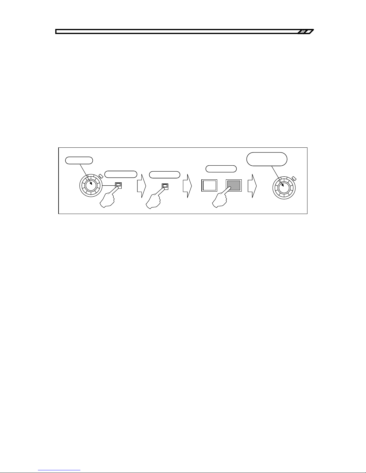
4.1 Operation example in constant voltage mode
HVA4321
4-11
When either of the above is not applicable, the internal high voltage DC power supply may be faulty.
In this case, it must be repaired.
4.1.4 Signal output and adjustment
a) Using internal DC bias signal source
Make sure that the internal DC signal source dial is 0. Set the polarity switch to the desired polarity. Turn
ON the internal DC bias signal source ON/OFF switch and press ON of the SIGNAL switch. While
reading the value on the voltmeter or oscilloscope connected to the voltage monitor, turn the dial
gradually to the right. Set it to the desired voltage.
Figure4-15. Using internal DC bias signal
b) Using external oscillator
Connect the external oscillator to OSC INPUT and make sure that the oscillator output level is 0V. Set the
GAIN knob to TOP. Turn ON the external oscillator ON/OFF switch and press ON of the SIGNAL switch.
While reading the value on the voltmeter or oscilloscope connected to the voltage monitor, increase the
output level of the oscillator gradually.
If fine adjustment of the output level is required, adjust it at the oscillator or adjust it with GAIN of the
unit. Turn GAIN to the left, the gain is decreased. Turn GAIN to the right, the gain is increased. The gain
can be adjusted in the range of approximately ±3%.
DC BIAS
0-10
kV
+
-
ON
OFF
SIGNAL
OFF
0にする。
極性を選ぶ。
ONにする。
ONにする。
希望のレベルに
調整する。
ON
DC BIAS
0-10
kV
Set to 0
Select polarity
Turn ON
Press ON
Adjust it to the
desired level.
Page 68
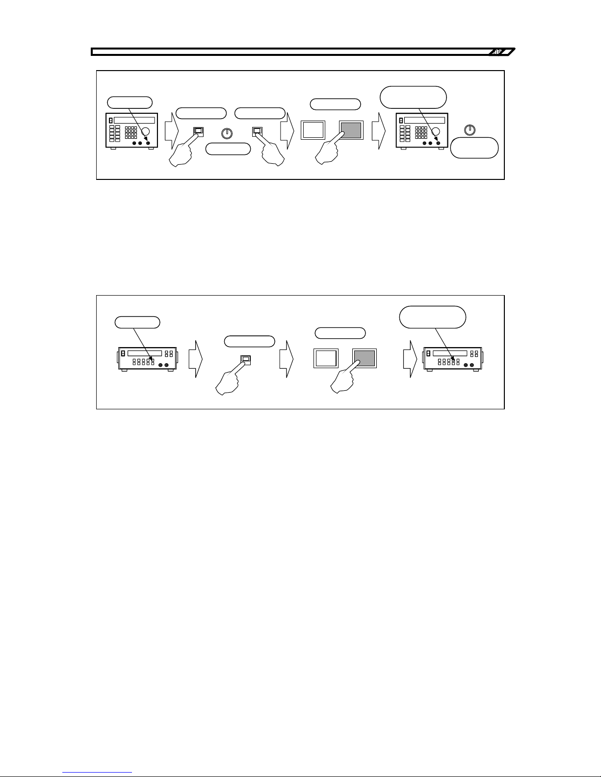
4.1 Operation example in constant voltage mode
HVA4321
4-12
Figure4-16. Using external oscillator
c) Using external DC bias signal source
Connect the DC standard power supply to EXT DC BIAS INPUT and make sure that the output of the
standard power supply is 0V. Turn ON the external DC bias ON/OFF switch and press ON of the SIGNAL
switch. While reading the value on the voltmeter or oscilloscope connected to the voltage monitor,
increase the output level of the DC standard power supply gradually and set the desired voltage.
Figure4-17. Using external DC bias signal
High voltage display
When the output voltage exceeds ±130V to ±150V, the high voltage output LED lights and starts
rotation slowly. The higher the output voltage is, the faster the rotation is.
When the voltage exceeds ±4.9 kV, the color changes from orange to red.
Gain adjustment with RESPONSE
The gain of 1 kHz band or more may vary depending on the RESPONSE knob position. Refer to "5.2
Characteristics in constant voltage mode, Chapter 5".
When the frequency is used at 1 kHz or more, measure the output voltage of the voltage monitor and
adjust RESPONSE so that the desired amplitude may be obtained.
ON
OFF
SIGNAL
OFF
0にする。
極性を選ぶ。
ONにする。
ONにする。
希望のレベルに
調整する。
ON
NORMAL
INVER
GAI N
真上にする。
GAI N
微調整する。
Set to 0
Select polarity Turn ON
Press ON
Adjust it to the
desired level.
Make fine
adjustment
Set to TOP
Oscillator
ON
OFF
SIGNAL
OFF
0にする。
ONにする。
ONにする。
希望のレベルに
調整する。
ON
Set to 0
Turn ON
Press ON
Adjust it to the
desired level.
DC standard power supply
Page 69
4.1 Operation example in constant voltage mode
HVA4321
4-13
!
!
It is very dangerous during output of high voltage. Never touch the output cable or the high voltage area.
If you find a dangerous status due to a unit error or load error, turn OFF the POWER switch immediately.
4.1.5 Signal OFF
a) Input signal OFF
To set the output signal to 0V temporarily, press OFF of the SIGNAL switch.
When SIGNAL is OFF, the output voltage is 0V, but the internal high voltage DC power supply is ON. It
continuously gives high voltage output.
In this status, never touch the output cable or the high voltage area for safety.
b) Internal high voltage DC power supply OFF
When the HIGH VOLTAGE POWER SUPPLY switch is turned OFF, the output of the internal high
voltage DC power supply is 0V and the amplifier cannot give high voltage output.
WARNING
WARNING
Page 70
4.2 Operation example in constant current mode (total)
HVA4321
4-14
!
!
4.2 Operation example in constant current mode (total)
This section describes operation example of this unit in total mode of constant current mode.
In constant current mode, the output current varies according to the input signal. If high frequency AC
signal is given at high voltage, leak current runs with stray capacitance between the cable and the ground.
Therefore, not all current from the output terminal of the unit goes to load.
In total mode, current including leak current due to cable capacity is controlled.
Set current = Leak current + Load current
Effect of stray capacitance of the cable is found only for AC signal output. Effect of stray signal is not
found for DC signal.
The TOTAL terminal of OUTPUT Lo is connected to the casing (= ground). Therefore, the total mode can
be used for grounded load or load that can be grounded.
When the internal high voltage DC power supply is ON and SIGNAL is ON with the output open,
maximum ±12 kV output is given to the OUTPUT Hi terminal. It is very dangerous.
Do not turn ON SIGNAL when the output is open.
In constant current mode, be sure to connect load or short-circuit the output.
When the internal high voltage DC power supply is ON and SIGNAL is OFF with the output open, ±100V
voltage output may be given to the OUTPUT Hi terminal depending on the voltage limiter settings.
In constant current mode, DC cannot be run for capacity load. At this time, the output for DC signal is the
same as that in open status. When SIGNAL is ON, maximum ±12 kV output is given to the OUTPUT Hi
terminal.
Never apply DC to capacity load in constant current mode.
WARNING
WARNING
Page 71
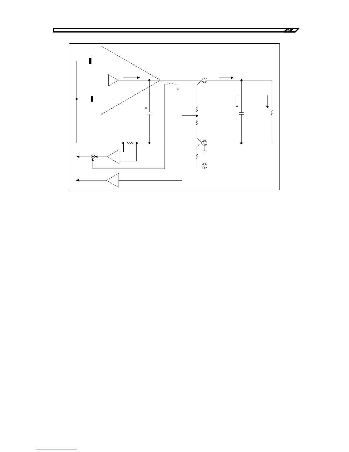
4.2 Operation example in constant current mode (total)
HVA4321
4-15
Figure4-18. Total mode
lamp : Output current of amplifier
lint : Leak current with internal capacity
lout : Output current
lstr : Leak current with wire capacity
lload : Load current
lac, ldc : DC and AC of detected current
Not all current lout from the output terminal is supplied to load. There is leak of lstr with wire capacity.
Actual current to load is lload = lout - lstr.
In total mode, control is made to satisfy set current = lout = lload + lstr.
In total mode, from output current lout, DC is detected with current detection resistance and AC is
detected with current transformer CT. Total output of leak current lstr with wire capacity and load current
lload is given to the current monitor.
(Leak current lint (AC) with stray capacity in the amplifier runs through the current detection resistance,
but only DC is detected here. The monitor is hardly affected.)
内部容量
出力端子
配線の容量
負荷抵抗
電流検出抵抗
電流検出抵抗
(トータル用)
(ロード用)
電流モニタ
OUTPUT Hi
OUTPUT Lo
TOTAL
LOAD
Iout
Ii nt
Istr
Il oad
Iamp
Iac
Idc
CT
電圧モニタ
Output terminal
Load
resistance
Wire capacit
y
Internal capacit
y
Current detection
resistance
(
for total
)
Current monitor
Voltage monitor
Current detection resistance
(for load)
Page 72
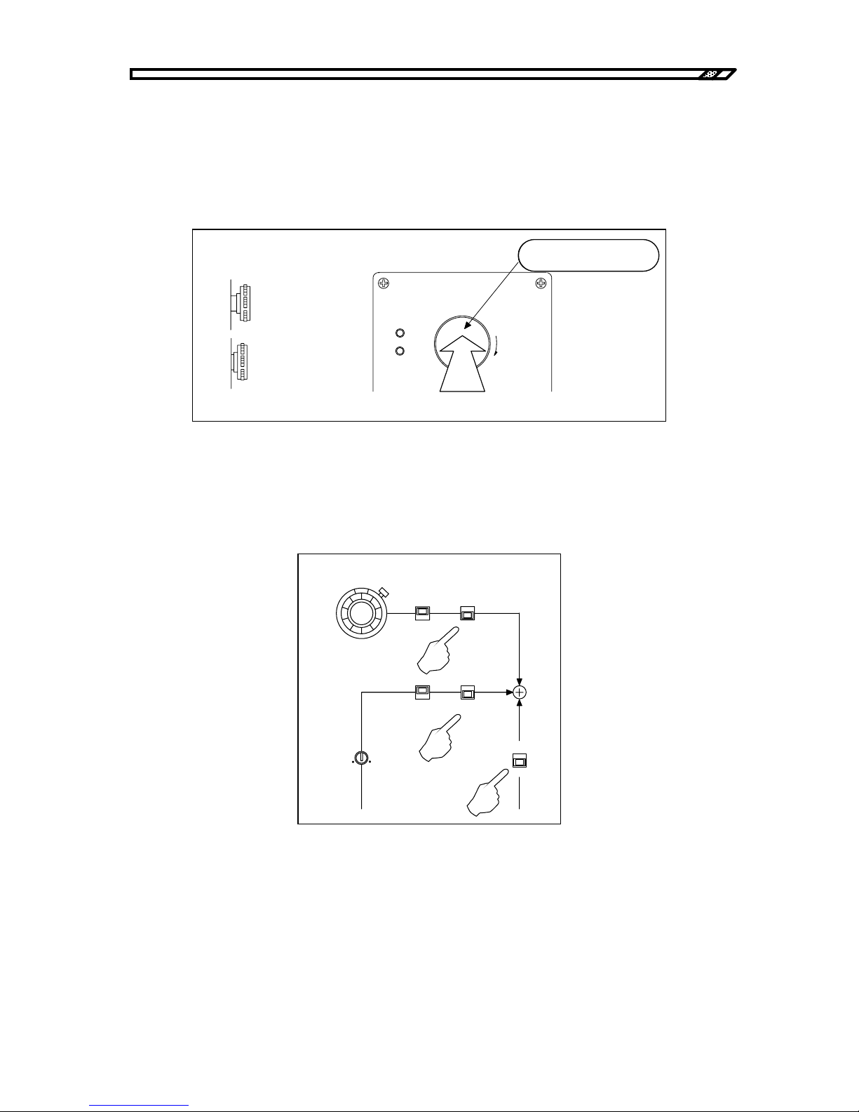
4.2 Operation example in constant current mode (total)
HVA4321
4-16
4.2.1 Panel setting
a) Internal high voltage DC power supply OFF
When HIGH VOLTAGE POWER SUPPLY is not OFF, press the button until a "click" sound is heard.
When a click sound is heard, the switch is locked in OFF status. The internal high voltage DC power
supply is always OFF.
Figure4-19. Internal high voltage DC power OFF
b) Signal system OFF
Turn the internal DC bias knob to the leftmost position to minimize the value. Turn OFF the switches of
DC BIAS, OSC INPUT and EXT DC BIAS INPUT.
Figure4-20. Switch settings
DC BIAS
0-10
kV
+
-
ON
OFF
ON
OFF
ON
OFF
INVERT
NORMAL
GAIN
HIGHVOLTAGE
POWER SUPPLY
PUSH OFF
ON
OFF
危険防止のた め 、 出力の配線を 変更する と き は必ず
上のス イ ッ チを 押し て H V 電源を O F F し て く だ さ い。
PULL ON
カチッと音がするまで
押し ます。
ロックされた状態
オフ
オン
側面より
From side
ON
OFF
Locked status
Press the switch until a click
sound is heard.
Page 73
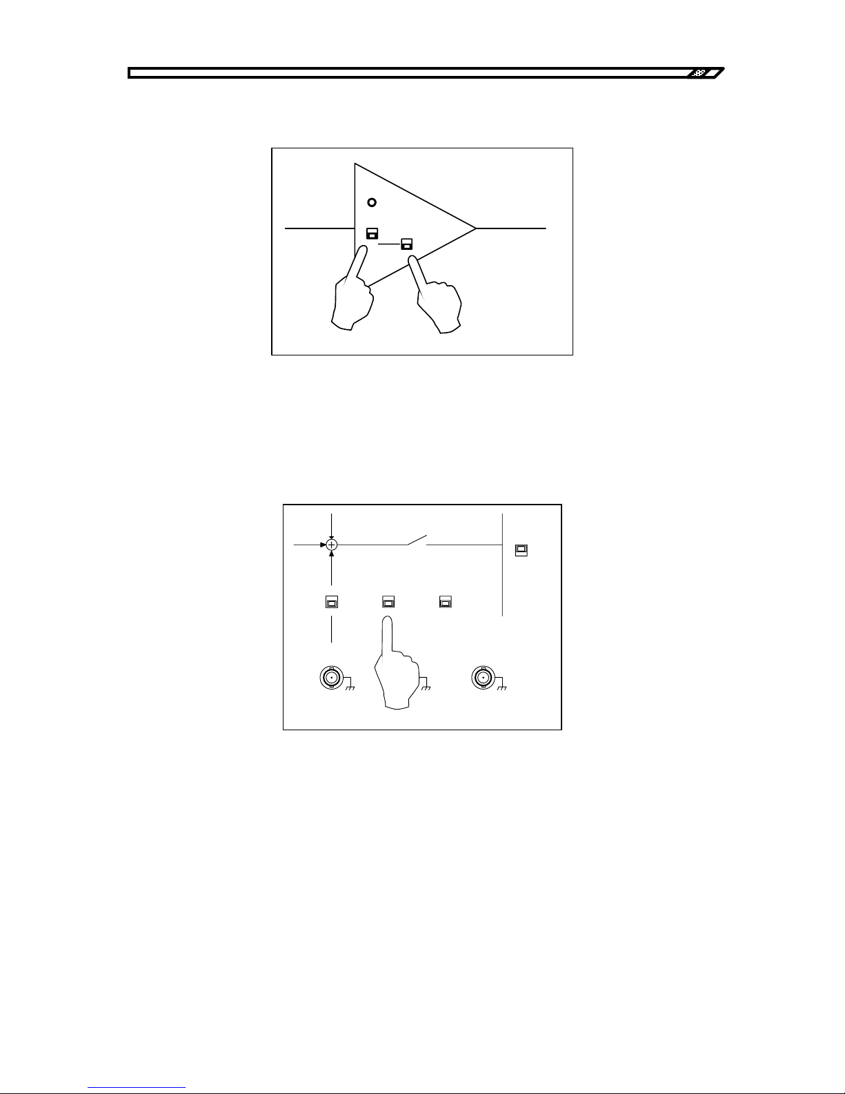
4.2 Operation example in constant current mode (total)
HVA4321
4-17
c) Output mode settings
Set the output mode switch to CC. Set the DC BIAS to CC.
Figure4-21. Output mode settings
d) Remote/local settings
To operate this unit from the panel, set the ON/OFF CONTROL switch to LOCAL.
Refer to "4.6 Remote control operation" for remote control operation.
Figure4-22. Local settings
OVERL OA D
CV
1kV/1V
CC
1mA/1V
DC BI AS
CV
CC
CV
1kV/1V
CC
1mA/1V
CURRENT
SELECT
LOAD
TOTAL
ON/OFF
CONTROL
REMOTE
LOCAL
ON
OFF
EXT DC BI AS
OUTPUT
TTL(Lo:ON)
Zout 10k
Ω
SI GNAL ON/OFF STATUS
OUTPUT
MONITOR
1V/1kV
Zout 50
Ω
VOLTAGE
CURRENT
±
10V MAX
Zi n 1 0 k
Ω
1V/ 1mA
Zout 50
Ω
Page 74
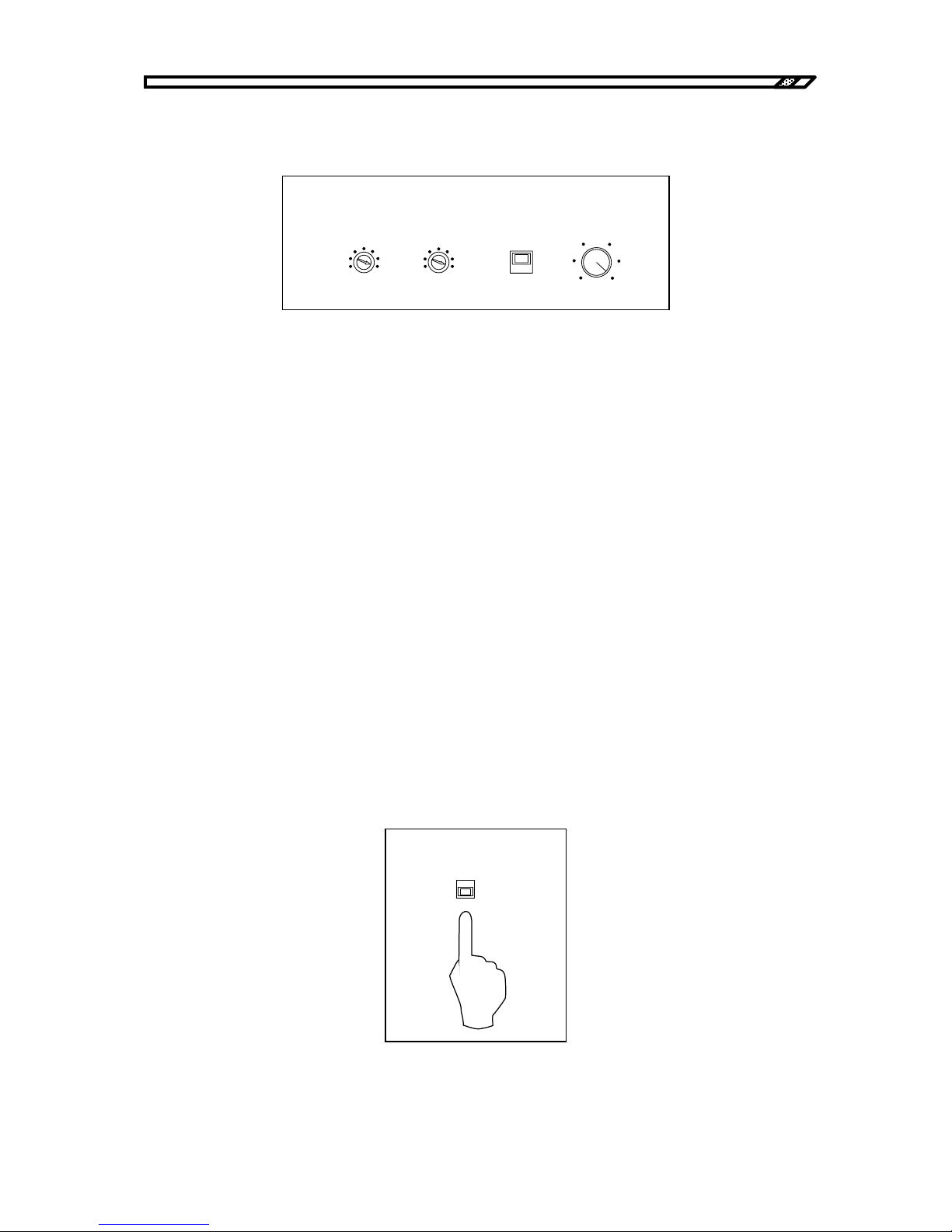
4.2 Operation example in constant current mode (total)
HVA4321
4-18
e) Output limiter settings
To limit the output voltage and output current, set the limiter level as required.
Figure4-23. Limiter settings
Voltage limiter
The voltage limiter function can limit the maximum value of the output voltage independently for
positive and negative values in the range from ±5 kV to ±10 kV.
For example, the output is sufficient up to ±8 kV, set the VOLTAGE LIMITER to 8 kV and -8 kV.
When voltage limitation is not required, set it to MAX.
Current limiter
The current limiter function can limit the average value of the output current in the range from 0 mA to
±10 mA.
For example, to limit the output current up to 5 mA, set it to 5 mA.
When current limitation is not required, set it to 10 mA which is turned to the rightmost position.
LIMIT/TRIP
Set the protection mode for activation of the current limiter. When LIMIT is selected, current is limited
to the set current. When TRIP is selected, the input signal is immediately OFF for activation of the
current limiter circuit and the output is 0V.
Select either one as required.
f) Current monitor mode settings
In total mode of constant current mode, set it to TOTAL CURRENT
Figure4-24. Current monitor mode settings
TRIP
VOLTAGE(kV)
-5
-10
MAX
5
10
MAX
LI MIT
DC CURRENT( mA)
0
10
LI MITER
CURRENT
SELECT
LOAD
TOTAL
Page 75
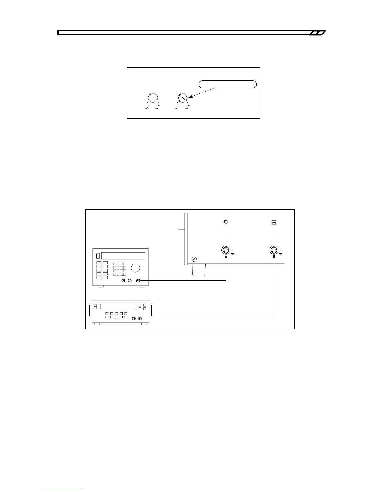
4.2 Operation example in constant current mode (total)
HVA4321
4-19
g) RESPONSE knob settings
Set the CC RESPONSE knob to the rightmost position.
.
Figure4-25. Response settings
4.2.2 Connection of signal source and connection of load
a) Connection of input signal source
Give the signal generator (e.g. oscillator) output to OSC INPUT. When applying the external DC bias,
give the DC signal source output to EXT DC BIAS INPUT.
The input voltage of the OSC INPUT terminal and the EXT DC BIAS INPUT terminal is maximum ±10V.
Figure4-26. Connection of external signal source signal
RESPONSE
CV CC
右に回しきります。
Turn to the rightmost
信号発生器
直流基準電源
ON
OFF
GAIN
OSC
INPUT
±
10V MAX
Zin 10k
Ω
EXT DC BI AS
OUTPUT
±
10V MAX
Zi n 1 0 k
Ω
Signal generator
DC standard power supply
Page 76
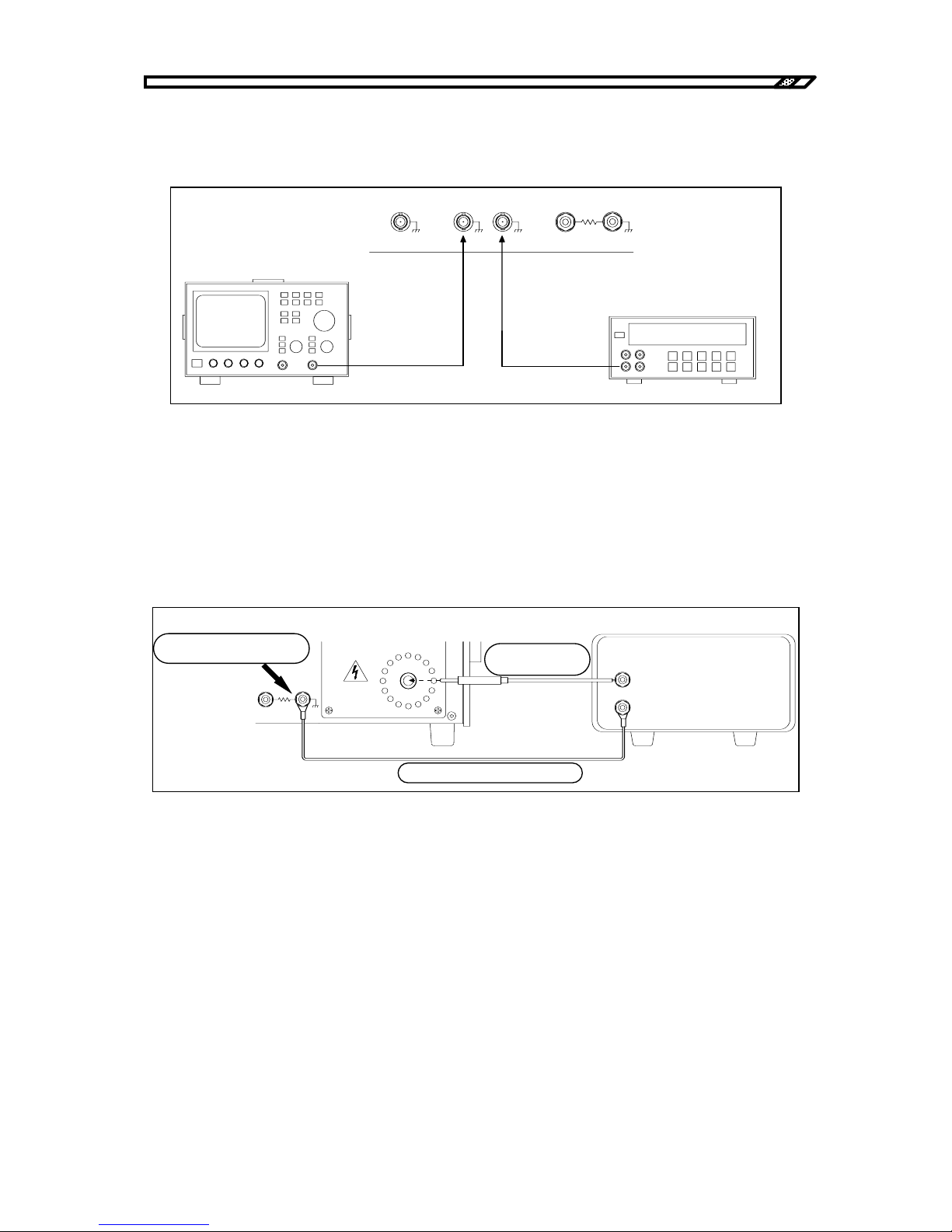
4.2 Operation example in constant current mode (total)
HVA4321
4-20
b) Monitor signal output
Connect a measuring instrument such as oscilloscope or voltmeter to VOLTAGE MONITOR or
CURRENT MONITOR as required.
Figure4-27. Connection of monitor
c) Connection of load
Be sure to use the accompanying cable for the cable connected to Hi.
To minimize effect from stray capacitance, shorten the cable length as much as possible and keep it away
from the floor or other devices.
Connect the return wire to the TOTAL CURRENT terminal.
Figure4-28. Connection of output cable
電圧計
SIGNAL ON/ OFF STAT US
OUTPUT
MONITOR
VOLTAGE
CURRENT
LOAD
CURRENT
TOTAL
CURRENT
OUTPUT L o
オシロスコ ープ
Voltmeter
Oscilloscope
LOAD
CURRENT
TOTAL
CURRENT
OUTPUT Lo
±
10kV MAX
±
10mA MAX
OUTPUT Hi
緩まな いよ う にし っ かり と
締めて く だ さ い。
負荷
附属の高圧ケー ブル
附属のリ タ ーン ケーブ ル
Tighten it securely
Accompanying high
volta
g
e cable
A
ccompanying return cable
Load
Page 77
4.2 Operation example in constant current mode (total)
HVA4321
4-21
!
In total mode, be sure to use the TOTAL CURRENT terminal. If the LOAD CURRENT terminal is used,
the operation may be faulty.
The TOTAL CURRENT terminal is connected to the casing.
Tighten the binding post terminal of OUTPUT Lo securely. If it is loose, electric shock may occur when
touching the load grounding or the return cable.
Check sometimes if it is not loose when it is safe with the power OFF.
WARNING
!
CAUTION
Page 78
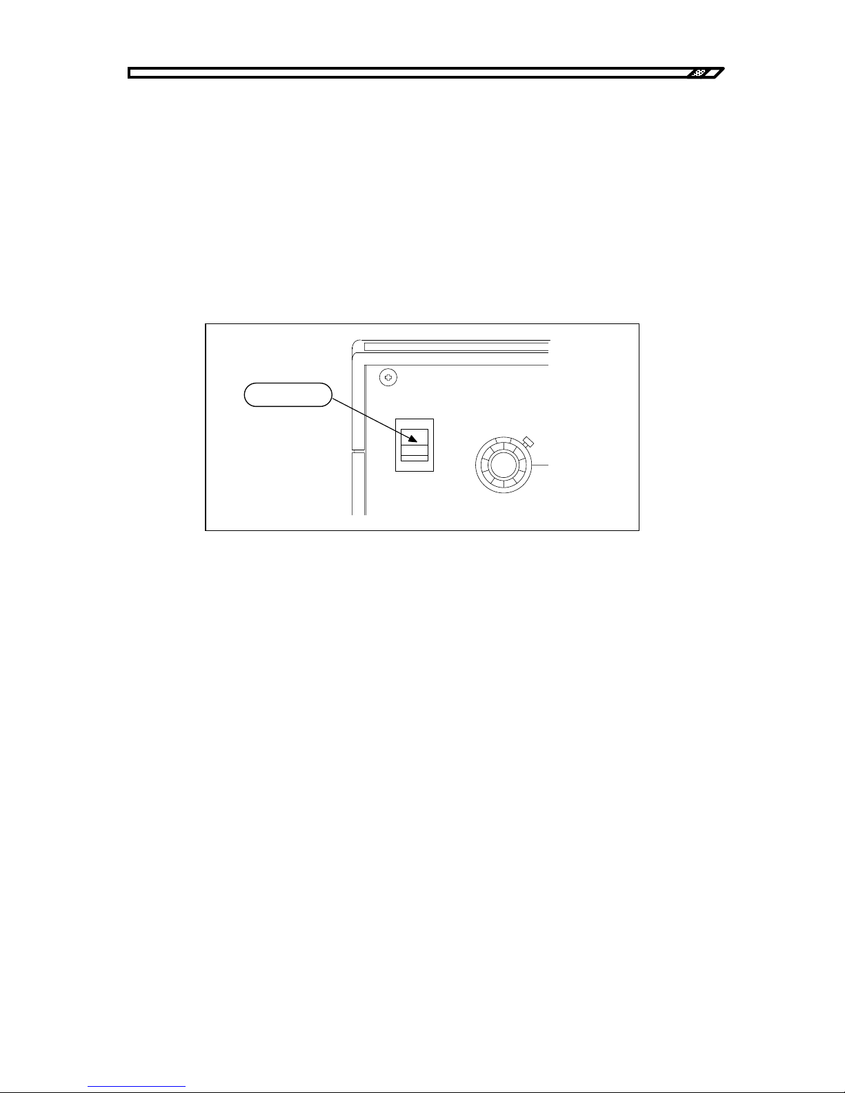
4.2 Operation example in constant current mode (total)
HVA4321
4-22
4.2.3 Power supply and internal high voltage DC power supply
a) Power supply
Before supply of power, check again if the HIGH VOLTAGE POWER SUPPLY switch is OFF (button is
pressed). After checking connection to load, connection to the signal source and if the panel settings are
correct, turn ON the POWER switch of the unit.
When the power is ON, the fan at the back starts operation.
On the panel surface:
・The OFF lamp of the signal switch blinks.
・The OFF LED of the internal high voltage DC power supply lights.
Figure4-29. Power supply
b) Supply of high voltage DC power
Turn the HIGH VOLTAGE POWER SUPPLY switch to the right and unlock it. Turn ON the internal high
voltage power supply. The ON LED of the internal high voltage power supply lights. In several seconds,
the SIGNAL switch OFF lamp changes from blinking to lighting.
When the power is supplied, the internal high voltage DC power supply is always OFF regardless of
ON/OFF status of the HIGH VOLTAGE POWER SUPPLY switch. If this switch is ON, turn OFF once
and turn it ON again.
POWER
DC BIAS
0-10
V
I
O
オンにし ます。
Turn ON.
Page 79
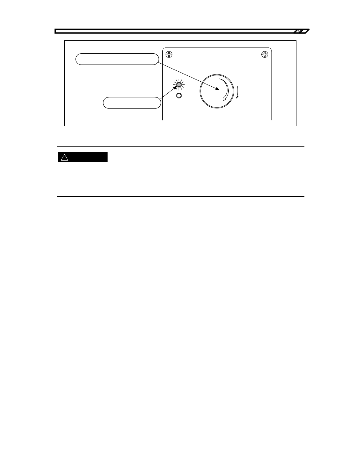
4.2 Operation example in constant current mode (total)
HVA4321
4-23
!
Figure4-30. Internal high voltage DC power ON
After this operation, the internal high voltage DC power supply is ON. High voltage is generated inside the
unit.
Be careful not to touch the area like an output terminal to which high voltage is applied.
○When the SIGNAL OFF switch remains blinking.
When the SIGNAL OFF switch remains blinking after unlocking the HIGH VOLTAGE POWER
SUPPLY switch, check the following:
1) Is the shorting plug inserted into the HIGH VOLTAGE POWER SUPPLY ON/OFF terminal at the
back?
Action
Insert the shorting plug for operation in LOCAL mode.
2) Is the DC CURRENT value the minimum and is TRIP selected?
Action
Increase the current limit or select LIMIT.
3) Is temperature of exhaust air extremely high?
Action
Temperature in the casing may be too high. Leave the unit at a cool environment for dozens of
minutes. Then, turn ON the HIGH VOLTAGE POWER SUPPLY switch again.
4) Are all fans at the back operating?
Action
Check if there is any object that blocks rotation of a fan. If a fan does not rotate without any
blocking, the fan may be faulty. It must be repaired.
WARNING
HIGHVOLTAGE
POWER SUPPLY
PUSH OFF
ON
OFF
危険防止の た め 、 出力の 配線を 変更す る と き は必ず
上の ス イ ッ チ を 押し て H V 電源を O F F し て く だ さ い 。
PULL ON
右に回して、ロックを解除します。
ONのLEDが点灯します。
Turn to the right for unlocking.
ON LED lights.
Be sure to press the above switch to turn OFF
the HV power for safety when the output wiring
is changed.
Page 80
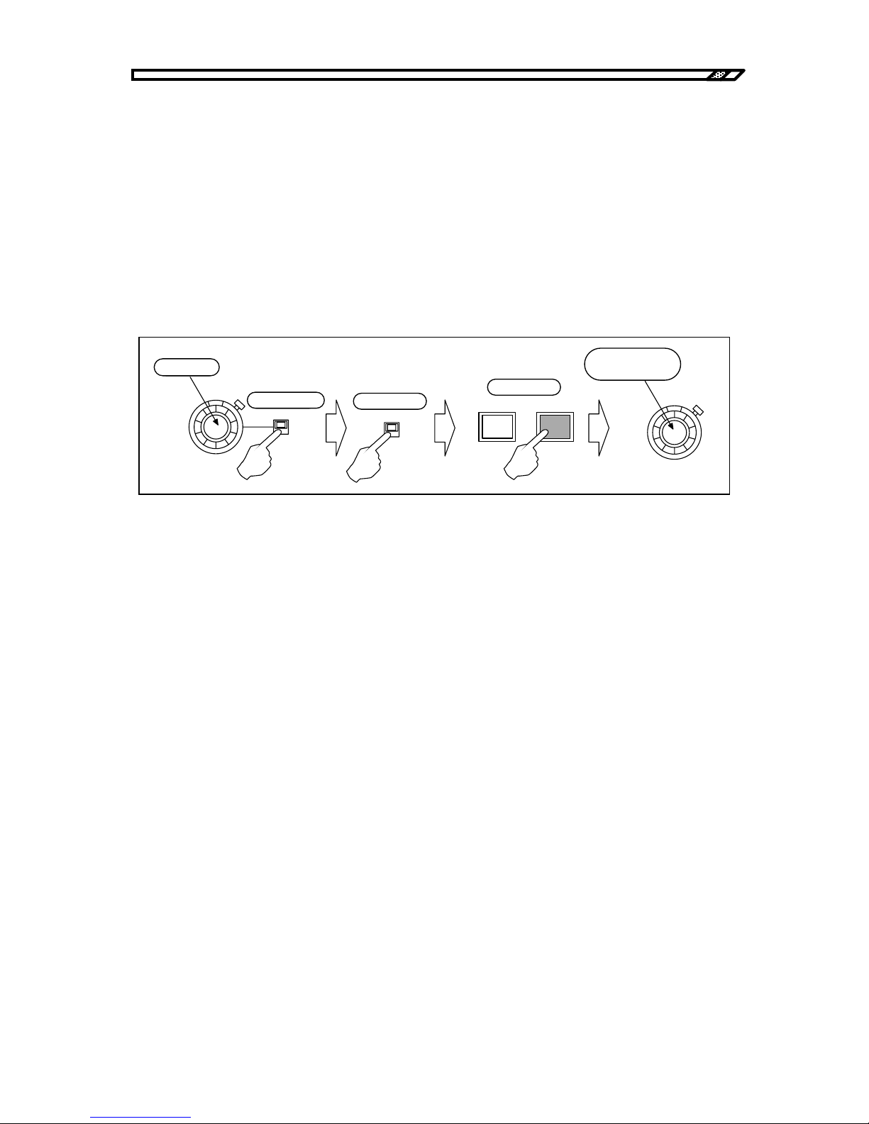
4.2 Operation example in constant current mode (total)
HVA4321
4-24
When either of the above is not applicable, the internal high voltage DC power supply may be faulty.
In this case, it must be repaired.
4.2.4 Signal output and adjustment
a) Using internal DC bias signal source
Make sure that the internal DC signal source dial is 0. Set the polarity switch to the desired polarity. Turn
ON the internal DC bias signal source ON/OFF switch and press ON of the SIGNAL switch. While
reading the value on the voltmeter or oscilloscope connected to the voltage monitor, turn the dial
gradually to the right. Set it to the desired voltage.
Figure4-31. Using internal DC bias signal
b) Using external oscillator
Connect the external oscillator to OSC INPUT and make sure that the oscillator output level is 0V. Set the
GAIN knob to TOP. Turn ON the external oscillator ON/OFF switch and press ON of the SIGNAL switch.
While reading the value on the voltmeter or oscilloscope connected to the voltage monitor, increase the
output level of the oscillator gradually.
If fine adjustment of the output level is required, adjust it at the oscillator or adjust it with GAIN of the
unit. Turn GAIN to the left, the gain is decreased. Turn GAIN to the right, the gain is increased. The gain
can be adjusted in the range of approximately ±3%.
DC BIAS
0-10
kV
+
-
ON
OFF
SIGNAL
OFF
0にする。
極性を選ぶ。
ONにする。
ONにする。
希望のレベルに
調整する。
ON
DC BIAS
0-10
kV
Set to 0
Select polarity
Turn ON
Press ON
Adjust it to the
desired level.
Page 81
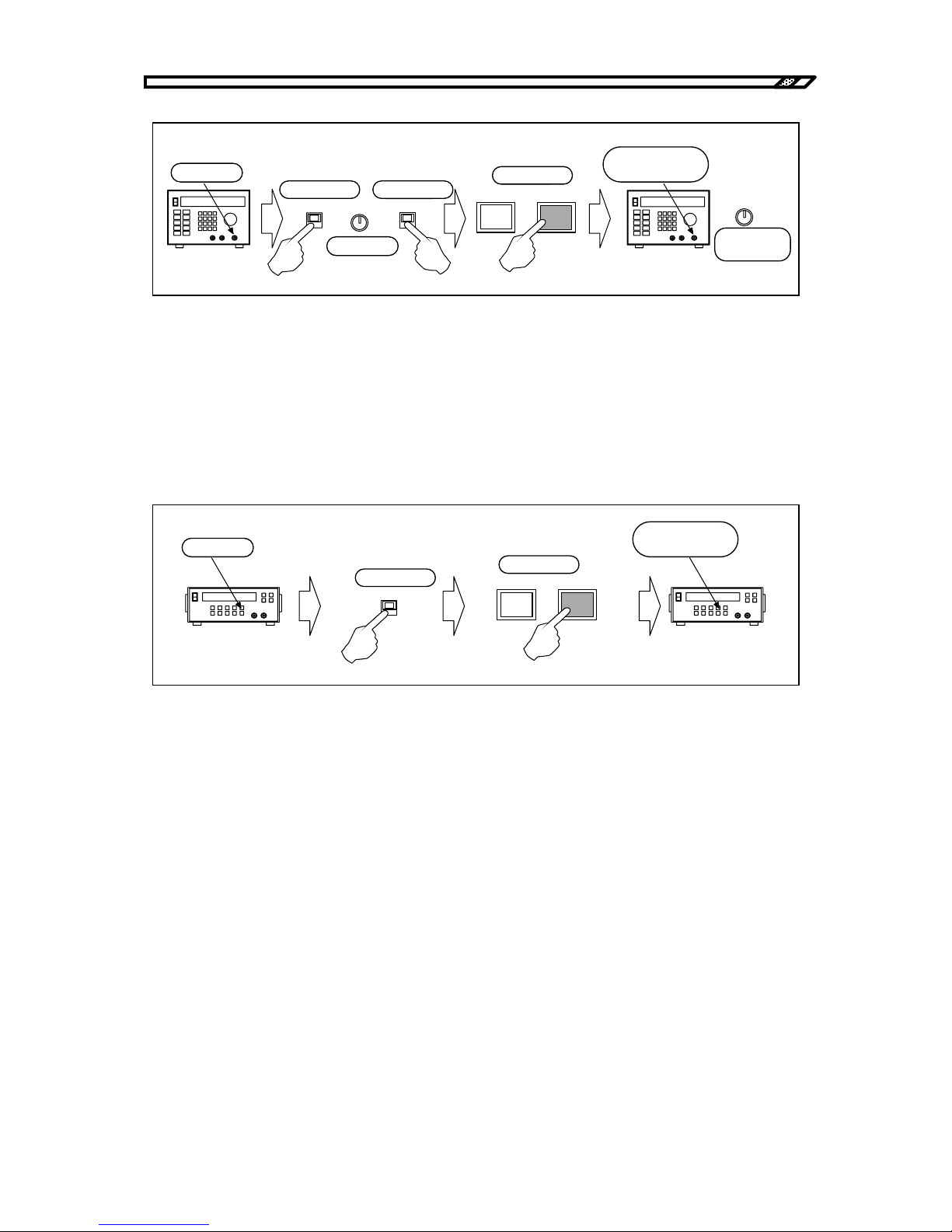
4.2 Operation example in constant current mode (total)
HVA4321
4-25
Figure4-32. Using external oscillator
c) Using external DC bias signal source
Connect the DC standard power supply to EXT DC BIAS INPUT and make sure that the output of the
standard power supply is 0V. Turn ON the external DC bias ON/OFF switch and press ON of the SIGNAL
switch.
While reading the value on the voltmeter or oscilloscope connected to the voltage monitor, increase the
output level of the DC standard power supply gradually and set the desired voltage.
Figure4-33. Using external DC bias signal
High voltage display
When the output voltage exceeds ±130V to ±150V, the high voltage output LED lights and starts
rotation slowly. The higher the output voltage is, the faster the rotation is.
When the voltage exceeds ±4.9 kV, the color changes from orange to red.
Gain adjustment with RESPONSE
The gain of 200 kHz band or more may vary depending on the RESPONSE knob position. Refer to
"5.3 Characteristics in constant voltage mode, Chapter 5".
When the frequency is used at 200 Hz or more, measure the output voltage of the voltage monitor and
adjust RESPONSE so that the desired amplitude may be obtained.
ON
OFF
SIGNAL
OFF
0にする。
極性を選ぶ。
ONにする。
ONにする。
希望のレベルに
調整する。
ON
NORMAL
INVER
GAI N
真上にする。
GAI N
微調整する。
Set to 0
Select polarity Turn ON
Press ON
Adjust it to the
desired level.
Make fine
adjustment
Set to TOP
Oscillator
ON
OFF
SIGNAL
OFF
0にする。
ONにする。
ONにする。
希望のレベルに
調整する。
ON
Set to 0
Turn ON
Press ON
Adjust it to the
desired level.
DC standard power supply
Page 82
4.2 Operation example in constant current mode (total)
HVA4321
4-26
!
!
It is very dangerous during output of high voltage. Never touch the output cable or the high voltage area.
If you find a dangerous status due to a unit error or load error, turn OFF the POWER switch immediately.
4.2.5 Signal OFF
a) Input signal OFF
To set the output signal to 0V temporarily, press OFF of the SIGNAL switch.
When SIGNAL is OFF, the output voltage is 0V, but the internal high voltage DC power supply is ON. It
continuously gives high voltage output.
In this status, never touch the output cable or the high voltage area for safety.
b) Internal high voltage DC power supply OFF
When the HIGH VOLTAGE POWER SUPPLY switch is turned OFF, the output of the internal high
voltage DC power supply is 0V and the amplifier cannot give high voltage output.
WARNING
WARNING
Page 83
4.3 Operation example in constant current mode (load)
HVA4321
4-27
!
!
4.3 Operation example in constant current mode (load)
This section describes operation example of this unit in load mode of constant current mode.
In constant current mode, the output current varies according to the input signal.
In load mode, load current is correctly controlled ignoring effect due to leak current with cable capacity.
Effect of stray capacitance of the cable is found only for AC signal output. Effect of stray signal is not
found for DC signal. Therefore, use the unit in total mode for DC signal.
In load mode, leak current with stray capacitance and load current are detected from different routes.
Therefore, load mode cannot be used for load which is grounded.
When the internal high voltage DC power supply is ON and SIGNAL is ON with the output open,
maximum ±12 kV output is given to the OUTPUT Hi terminal. It is very dangerous. Do not turn ON
SIGNAL when the output is open.
In constant current mode, be sure to connect load or short-circuit the output.
When the internal high voltage DC power supply is ON and SIGNAL is OFF with the output open, ±100V
voltage output may be given to the OUTPUT Hi terminal depending on the voltage limiter settings.
In constant current mode, DC cannot be run for capacity load. At this time, the output for DC signal is the
same as that in open status. When SIGNAL is ON, maximum ±12 kV output is given to the OUTPUT Hi
terminal.
Never apply DC to capacity load in constant current mode.
WARNING
WARNING
Page 84
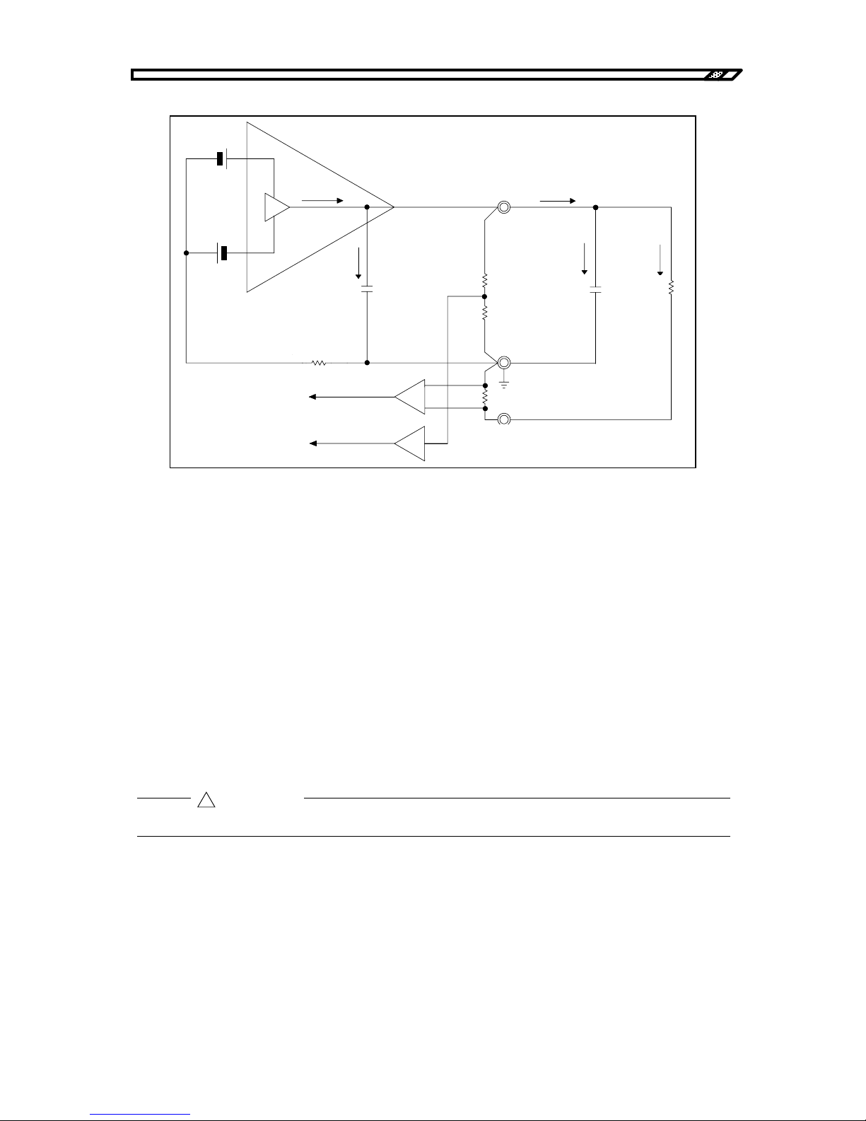
4.3 Operation example in constant current mode (load)
HVA4321
4-28
Figure4-34. Load mode
lamp : Output current of amplifier
lint : Leak current with internal capacity
lout : Output current
lstr : Leak current with wire capacity
lload : Load current
lac, ldc : DC and AC of detected current
Not all current lout from the output terminal is supplied to load. There is leak of lstr with wire capacity.
Actual current to load is lload = lout - lstr.
In load mode, lload and lstr are returned through different routes and only lload is detected to control
output current.
Therefore, Set current = lload
lout = lload + lstr
Current lout from the output terminal cannot exceed the maximum current of this unit.
In load mode, load current is directly detected. Only load current can be monitored with the current
monitor.
内部容量
出力端子
配線の容量
負荷抵抗
電流検出抵抗
電流検出抵抗
(トータル用)
(ロード用)
電流モニタ
OUTPUT Hi
OUTPUT Lo
TOTAL
LOAD
Iout
Ii nt
Istr
Il oad
Iamp
Idc+Iac
電圧モニタ
Output terminal
Load
resistance
Wire capacit
y
Internal capacit
y
Current detection
resistance
(
for total
)
Current monitor
Voltage monitor
Current detection resistance
(for load)
!
CAUTION
Page 85
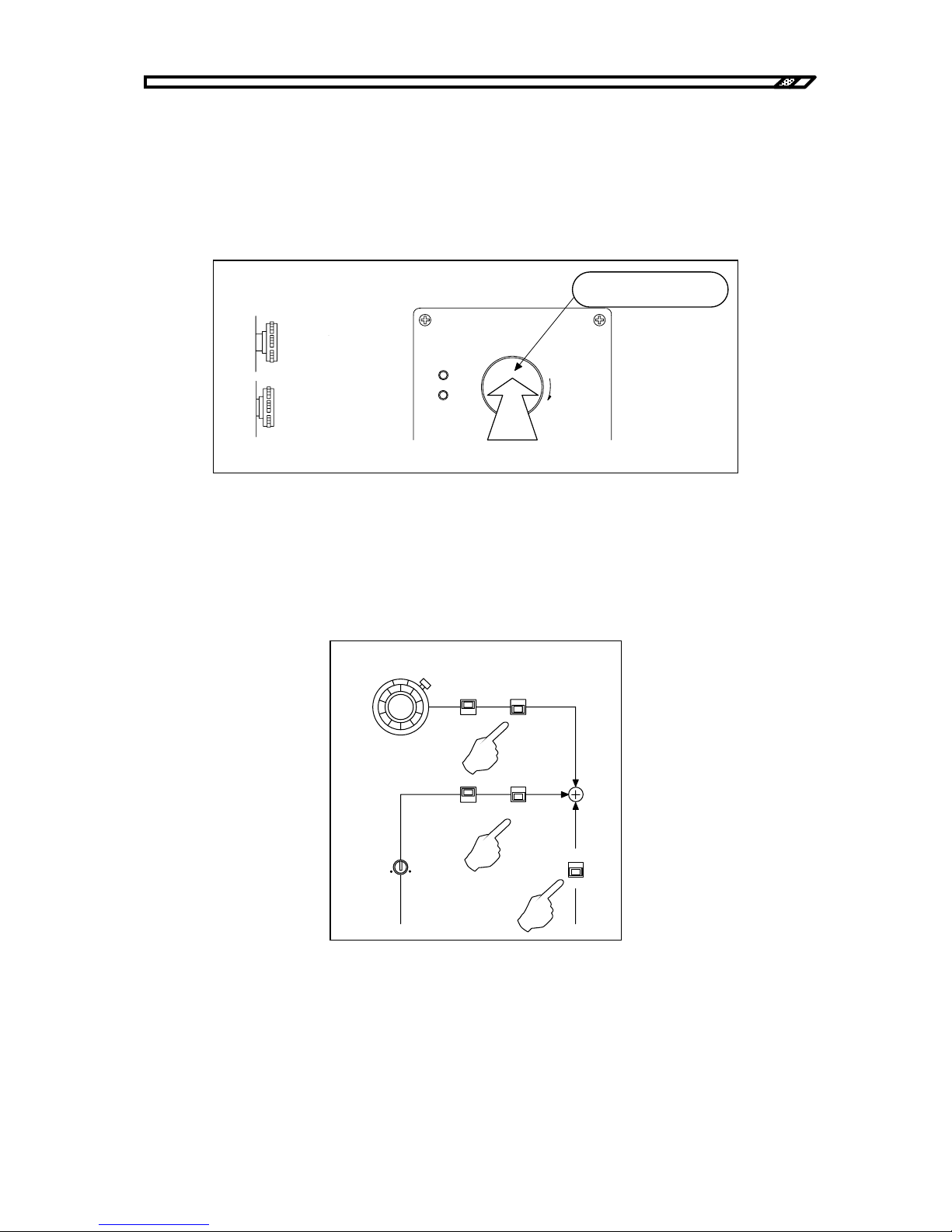
4.3 Operation example in constant current mode (load)
HVA4321
4-29
4.3.1 Panel setting
a) Internal high voltage DC power supply OFF
When HIGH VOLTAGE POWER SUPPLY is not OFF, press the button until a "click" sound is heard.
When a click sound is heard, the switch is locked in OFF status. The internal high voltage DC power
supply is always OFF.
Figure4-35. Internal high voltage DC power OFF
b) Signal system OFF
Turn the internal DC bias knob to the leftmost position to minimize the value. Turn OFF the switches of
DC BIAS, OSC INPUT and EXT DC BIAS INPUT.
Figure4-36. Switch settings
DC BIAS
0-10
kV
+
-
ON
OFF
ON
OFF
ON
OFF
INVERT
NORMAL
GAIN
HIGHVOLTAGE
POWER SUPPLY
PUSH OFF
ON
OFF
危険防止のた め 、 出力の配線を 変更する と き は必ず
上のス イ ッ チを 押し て H V 電源を O F F し て く だ さ い。
PULL ON
カチッと音がするまで
押し ます。
ロックされた状態
オフ
オン
側面より
From side
ON
OFF
Locked status
Press the switch until a click
sound is heard.
Page 86
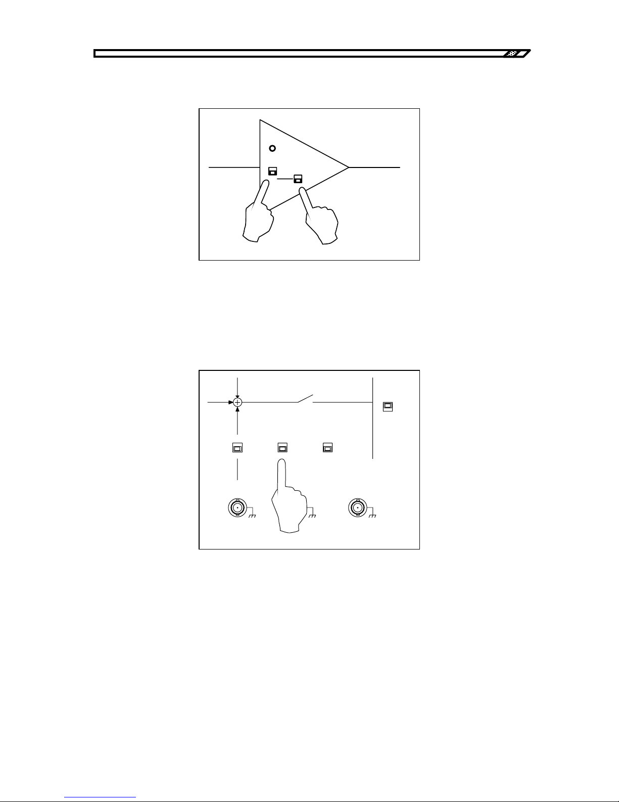
4.3 Operation example in constant current mode (load)
HVA4321
4-30
c) Output mode settings
Set the output mode switch to CC. Set the DC BIAS to CC.
Figure4-37. Output mode settings
d) Remote/local settings
To operate this unit from the panel, set the ON/OFF CONTROL switch to LOCAL.
Refer to "4.6 Remote control operation" for remote control operation.
Figure4-38. Local settings
OVERL OA D
CV
1kV/1V
CC
1mA/1V
DC BI AS
CV
CC
CV
1kV/1V
CC
1mA/1V
CURRENT
SELECT
LOAD
TOTAL
ON/OFF
CONTROL
REMOTE
LOCAL
ON
OFF
EXT DC BIAS
OUTPUT
TTL(Lo: ON)
Zout 10k
Ω
SIGNAL ON/ OFF STAT US
OUTPUT
MONITOR
1V/1kV
Zout 50
Ω
VOLTAGE
CURRENT
±
10V MAX
Zi n 10 k
Ω
1V/1mA
Zout 50
Ω
Page 87
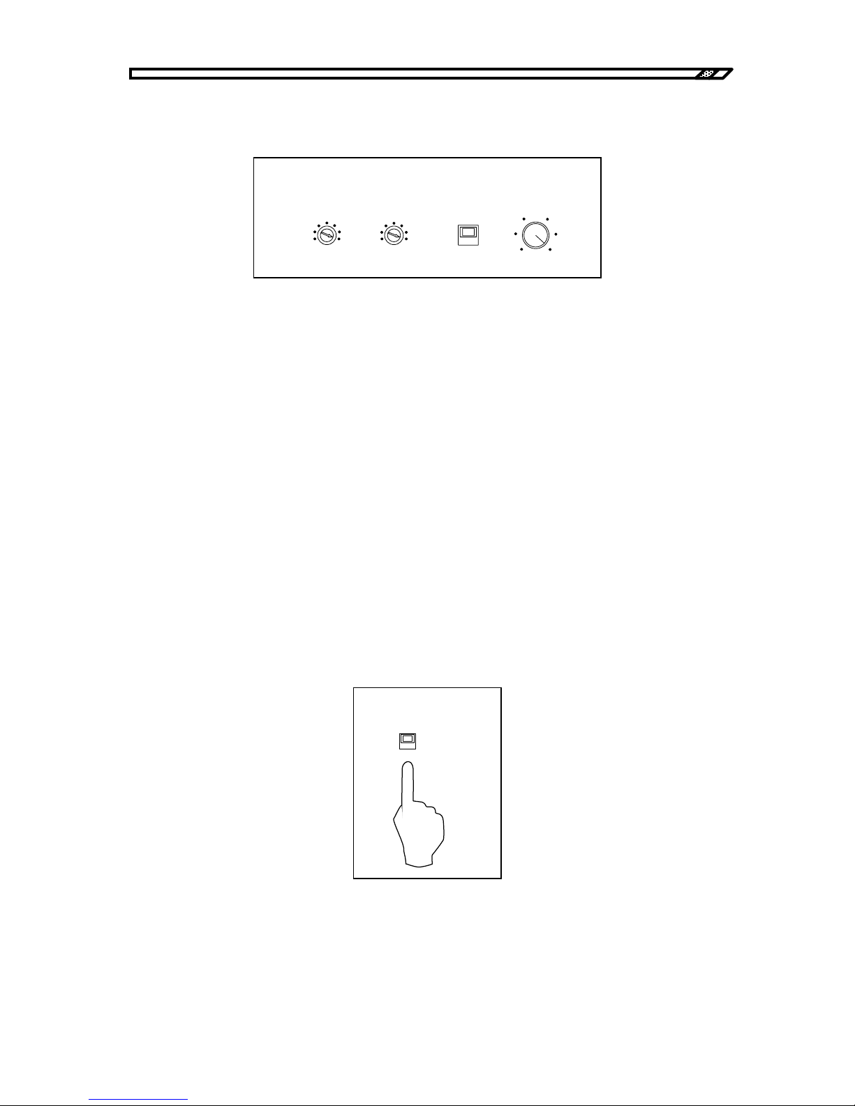
4.3 Operation example in constant current mode (load)
HVA4321
4-31
e) Output limiter settings
To limit the output voltage and output current, set the limiter level as required.
Figure4-39. Limiter settings
Voltage limiter
The voltage limiter function can limit the maximum value of the output voltage independently for
positive and negative values in the range from ±5 kV to ±10 kV. For example, the output is sufficient
up to ±8 kV, set the VOLTAGE LIMITER to 8 kV and -8 kV.
When voltage limitation is not required, set it to MAX.
Current limiter
The current limiter function can limit the average value of the output current in the range from 0 mA to
±10 mA. For example, to limit the output current up to 5 mA, set it to 5 mA.
When current limitation is not required, set it to 10 mA which is turned to the rightmost position.
LIMIT/TRIP
Set the protection mode for activation of the current limiter. When LIMIT is selected, current is limited
to the set current. When TRIP is selected, the input signal is immediately OFF for activation of the
current limiter circuit and the output is 0V.
Select either one as required.
f) Current monitor mode settings
In load mode of constant current mode, set it to LOAD CURRENT.
Figure4-40. Current monitor mode settings
TRIP
VOLTAGE(kV)
-5
-10
MAX
5
10
MAX
LI MIT
DC CURRENT( mA)
0
10
LI MITER
CURRENT
SELECT
LOAD
TOTAL
Page 88
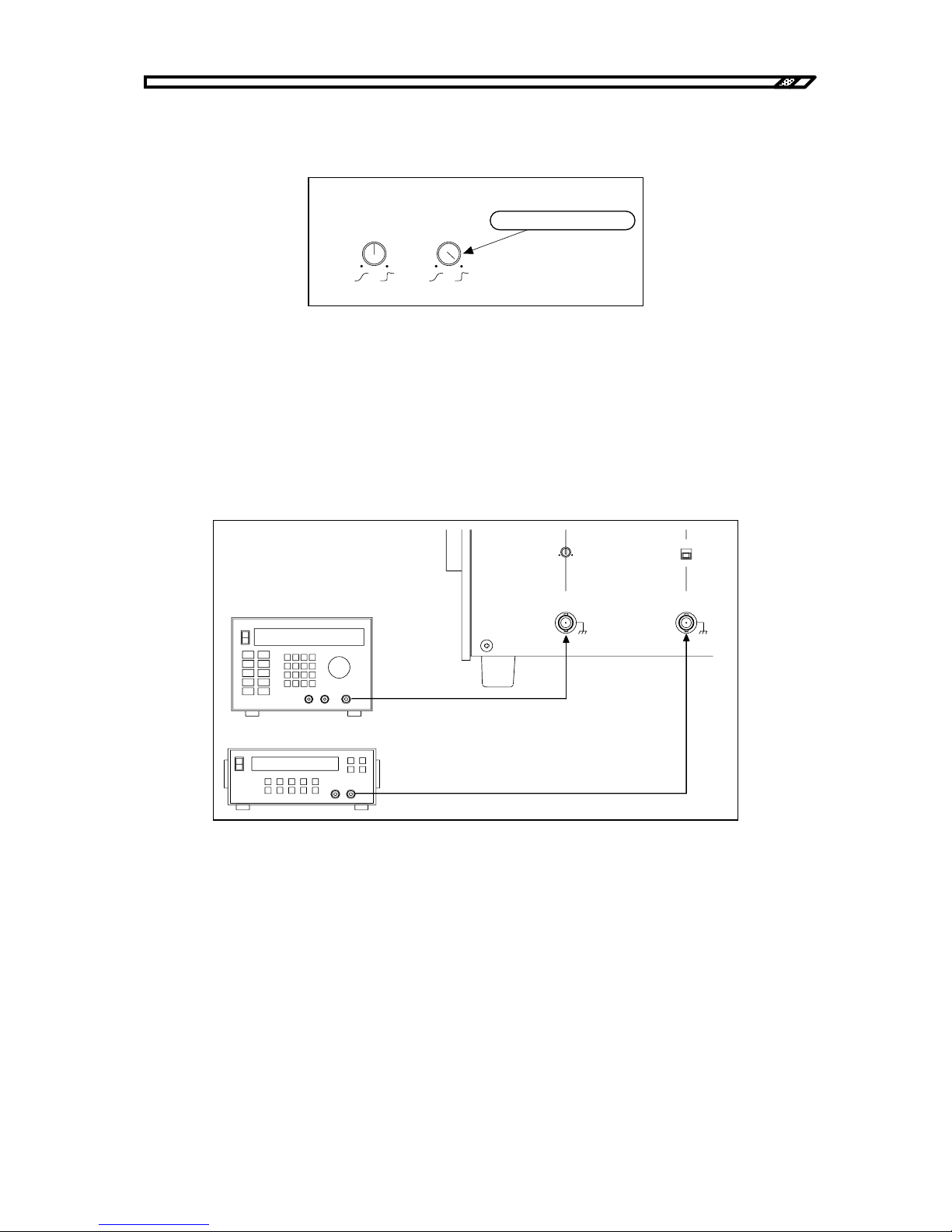
4.3 Operation example in constant current mode (load)
HVA4321
4-32
g) RESPONSE knob settings
Set the CC RESPONSE knob to the rightmost position.
Figure4-41. Response settings
4.3.2 Connection of signal source and connection of load
a) Connection of input signal source
Give the signal generator (e.g. oscillator) output to OSC INPUT. When applying the external DC bias,
give the DC signal source output to EXT DC BIAS INPUT.
The input voltage of the OSC INPUT terminal and the EXT DC BIAS INPUT terminal is maximum ±10V.
Figure4-42. Connection of external signal source signal
RESPONSE
CV CC
右に回しきります。
Turn to the rightmost
信号発生器
直流基準電源
ON
OFF
GAIN
OSC
INPUT
±
10V MAX
Zin 10k
Ω
EXT DC BI AS
OUTPUT
±
10V MAX
Zi n 1 0 k
Ω
Signal generator
DC standard power supply
Page 89
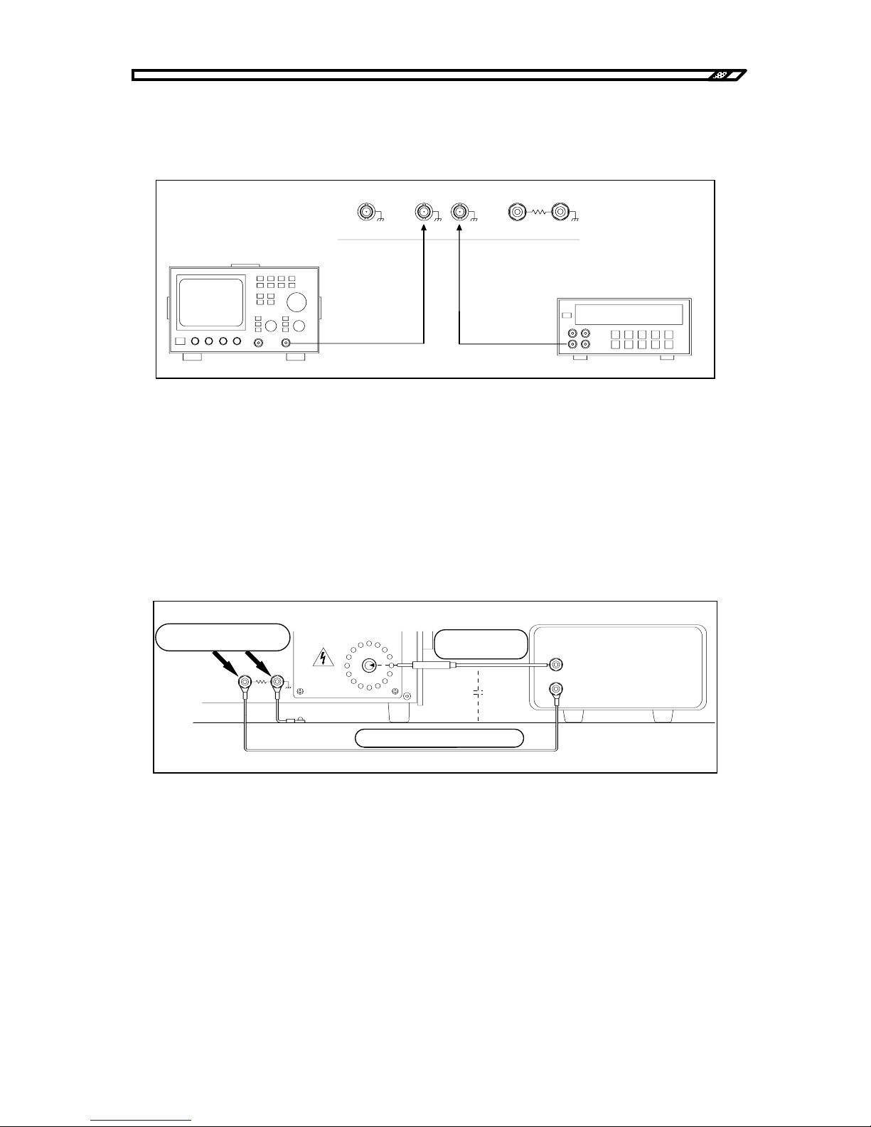
4.3 Operation example in constant current mode (load)
HVA4321
4-33
b) Monitor signal output
Connect a measuring instrument such as oscilloscope or voltmeter to VOLTAGE MONITOR or
CURRENT MONITOR as required.
Figure4-43. Connection of monitor
c) Connection of load
Be sure to use the accompanying cable for the cable connected to Hi.
To minimize effect from stray capacitance, shorten the cable length as much as possible and keep it away
from the floor or other devices.
Connect the return wire from load to the LOAD CURRENT terminal. Connect the ground line where leak
current runs with stray capacitance to the TOTAL CURRENT terminal.
Figure4-44. Connection of output cable
電圧計
SIGNAL ON/ OFF STAT US
OUTPUT
MONITOR
VOLTAGE
CURRENT
LOAD
CURRENT
TOTAL
CURRENT
OUTPUT L o
オシロスコ ープ
Voltmeter
Oscilloscope
LOAD
CURRENT
TOTAL
CURRENT
OUTPUT Lo
±
10kV MAX
±
10mA MAX
OUTPUT Hi
緩まな いよ う にし っ かり と
締めてく ださ い 。
負荷
附属の高圧ケーブ ル
附属のリ タ ーン ケーブ ル
グランドプレーンなど
浮遊容量
Tighten it securely
Accompanying high
voltage cable
A
ccompanying return cable
Load
Ground plane, etc.
Stray
ca
p
acitance
Page 90
4.3 Operation example in constant current mode (load)
HVA4321
4-34
!
In load mode, be sure to use the LOAD CURRENT terminal for the return terminal of load current.
Use the TOTAL CURRENT terminal for the return terminal of leak current.
Tighten the binding post terminal of OUTPUT Lo securely. If it is loose, electric shock may occur when
touching the load grounding or the return cable.
Check sometimes if it is not loose when it is safe with the power OFF.
WARNING
!
CAUTION
Page 91
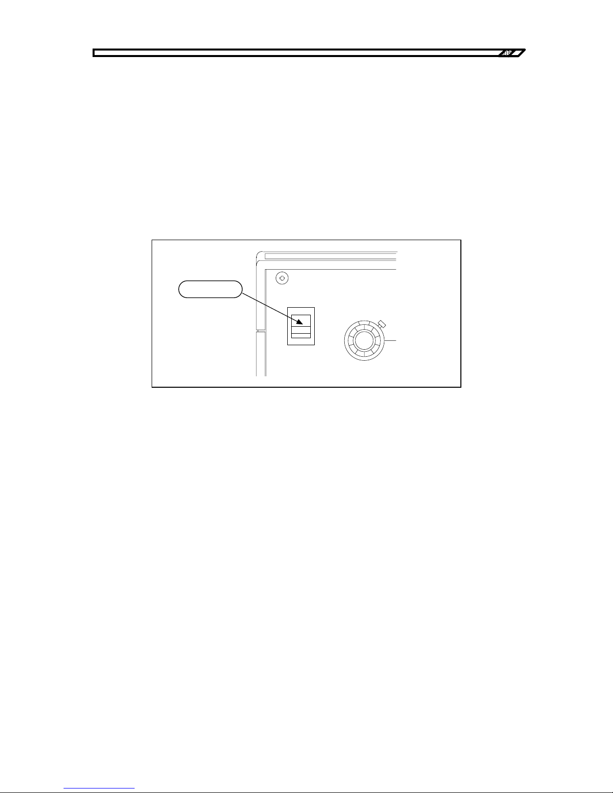
4.3 Operation example in constant current mode (load)
HVA4321
4-35
4.3.3 Power supply and internal high voltage DC power supply
a) Power supply
Before supply of power, check again if the HIGH VOLTAGE POWER SUPPLY switch is OFF (button is
pressed). After checking connection to load, connection to the signal source and if the panel settings are
correct, turn ON the POWER switch of the unit.
When the power is ON, the fan at the back starts operation.
On the panel surface:
・The OFF lamp of the signal switch blinks.
・The OFF LED of the internal high voltage DC power supply lights.
Figure4-45. Power supply
b) Supply of high voltage DC power
Turn the HIGH VOLTAGE POWER SUPPLY switch to the right and unlock it. Turn ON the internal high
voltage power supply. The ON LED of the internal high voltage power supply lights. In several seconds,
the SIGNAL switch OFF lamp changes from blinking to lighting.
When the power is supplied, the internal high voltage DC power supply is always OFF regardless of
ON/OFF status of the HIGH VOLTAGE POWER SUPPLY switch. If this switch is ON, turn OFF once
and turn it ON again.
POWER
DC BIAS
0-10
V
I
O
オンにし ます。
Turn ON.
Page 92
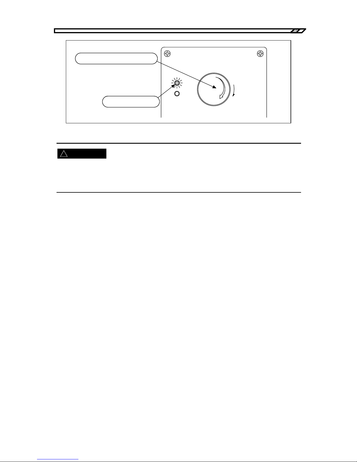
4.3 Operation example in constant current mode (load)
HVA4321
4-36
!
Figure4-46. Internal high voltage DC power ON
After this operation, the internal high voltage DC power supply is ON. High voltage is generated inside the
unit.
Be careful not to touch the area like an output terminal to which high voltage is applied.
○When the SIGNAL OFF switch remains blinking.
When the SIGNAL OFF switch remains blinking after unlocking the HIGH VOLTAGE POWER
SUPPLY switch, check the following:
1) Is the shorting plug inserted into the HIGH VOLTAGE POWER SUPPLY ON/OFF terminal at the
back?
Action
Insert the shorting plug for operation in LOCAL mode.
2) Is the DC CURRENT value the minimum and is TRIP selected?
Action
Increase the current limit or select LIMIT.
3) Is temperature of exhaust air extremely high?
Action
Temperature in the casing may be too high. Leave the unit at a cool environment for dozens of
minutes. Then, turn ON the HIGH VOLTAGE POWER SUPPLY switch again.
4) Are all fans at the back operating?
Action
Check if there is any object that blocks rotation of a fan. If a fan does not rotate without any
blocking, the fan may be faulty. It must be repaired.
WARNING
HIGHVOLTAGE
POWER SUPPLY
PUSH OFF
ON
OFF
危険防止の た め 、 出力の 配線を 変更す る と き は 必ず
上の ス イ ッ チ を 押し て H V 電源を O F F し て く だ さ い 。
PULL ON
右に回して、ロックを解除します。
ONのLEDが点灯します。
Turn to the right for unlocking.
ON LED lights.
Be sure to press the above switch to turn OFF
the HV power for safety when the output wiring
is changed.
Page 93
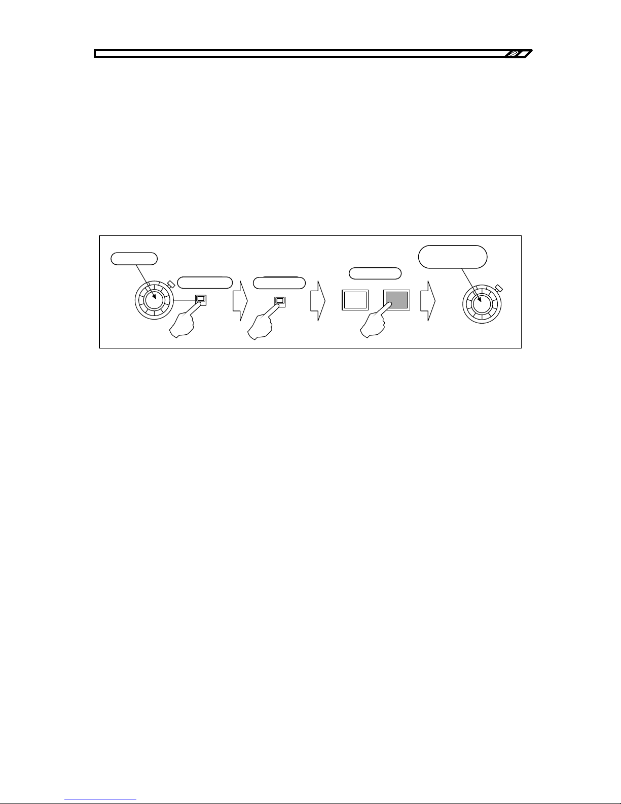
4.3 Operation example in constant current mode (load)
HVA4321
4-37
When either of the above is not applicable, the internal high voltage DC power supply may be faulty.
In this case, it must be repaired.
4.3.4 Signal output and adjustment
a) Using internal DC bias signal source
Make sure that the internal DC signal source dial is 0. Set the polarity switch to the desired polarity. Turn
ON the internal DC bias signal source ON/OFF switch and press ON of the SIGNAL switch. While
reading the value on the voltmeter or oscilloscope connected to the voltage monitor, turn the dial
gradually to the right. Set it to the desired voltage.
Figure4-47. Using internal DC bias signal
b) Using external oscillator
Connect the external oscillator to OSC INPUT and make sure that the oscillator output level is 0V. Set the
GAIN knob to UP. Turn ON the external oscillator ON/OFF switch and press ON of the SIGNAL switch.
While reading the value on the voltmeter or oscilloscope connected to the voltage monitor, increase the
output level of the oscillator gradually.
If fine adjustment of the output level is required, adjust it at the oscillator or adjust it with GAIN of the
unit. Turn GAIN to the left, the gain is decreased. Turn GAIN to the right, the gain is increased. The gain
can be adjusted in the range of approximately ±3%.
DC BIAS
0-10
kV
+
-
ON
OFF
SIGNAL
OFF
0にする。
極性を選ぶ。
ONにする。
ONにする。
希望のレベルに
調整する。
ON
DC BIAS
0-10
kV
Set to 0
Select polarity
Turn ON
Press ON
Adjust it to the
desired level.
Page 94
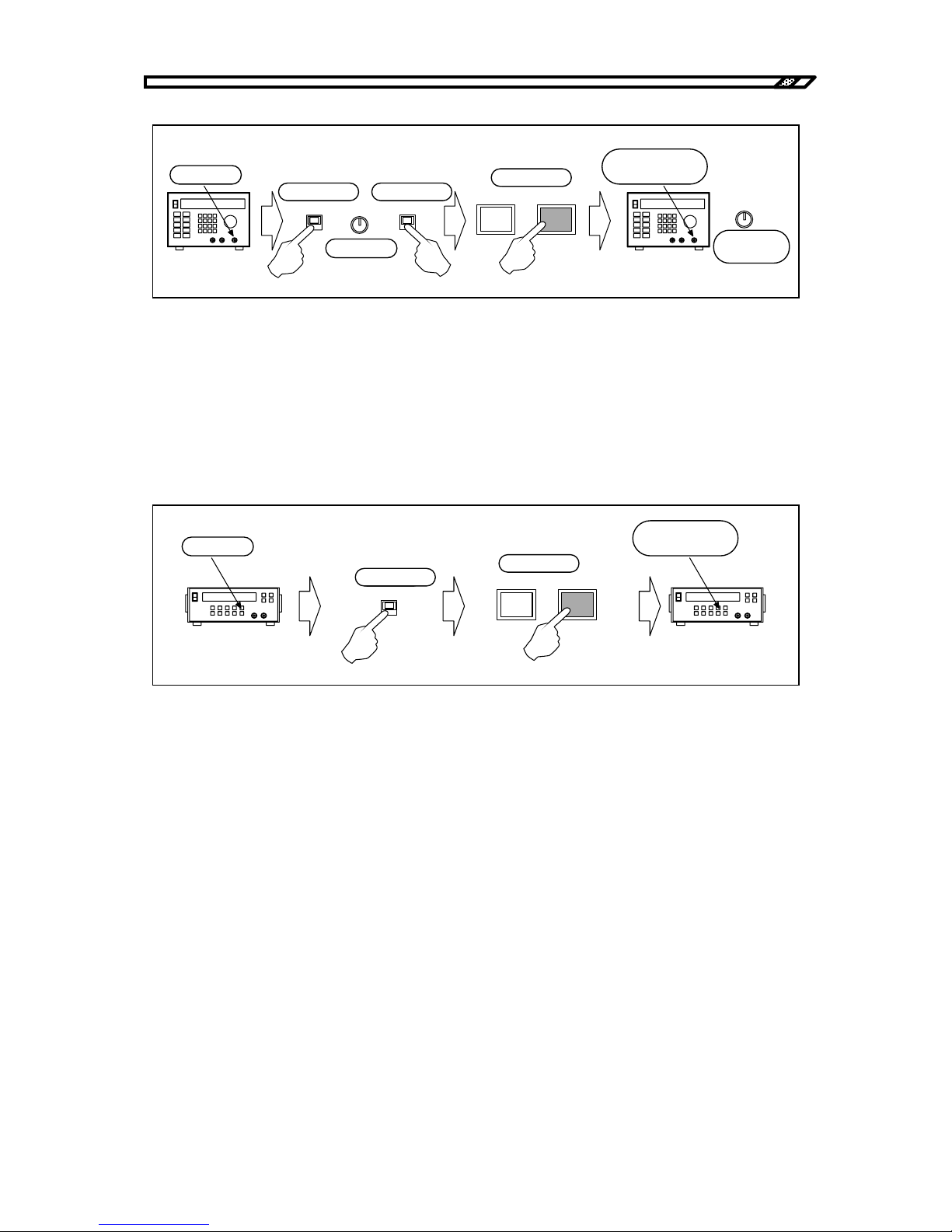
4.3 Operation example in constant current mode (load)
HVA4321
4-38
Figure4-48. Using external oscillator
c) Using external DC bias signal source
Connect the DC standard power supply to EXT DC BIAS INPUT and make sure that the output of the
standard power supply is 0V. Turn ON the external DC bias ON/OFF switch and press ON of the SIGNAL
switch.
While reading the value on the voltmeter or oscilloscope connected to the voltage monitor, increase the
output level of the DC standard power supply gradually and set the desired voltage.
Figure4-49. Using external DC bias signal
High voltage display
When the output voltage exceeds ±130V to ±150V, the high voltage output LED lights and starts
rotation slowly. The higher the output voltage is, the faster the rotation is.
When the voltage exceeds ±4.9 kV, the color changes from orange to red.
Gain adjustment with RESPONSE
The gain of the 200 Hz band or more may vary depending on the RESPONSE knob position. Refer to
"5.3 Characteristics in constant voltage mode, Chapter 5".
When the frequency is used at 200 Hz or more, measure the output voltage of the voltage monitor and
adjust RESPONSE so that the desired amplitude may be obtained.
ON
OFF
SIGNAL
OFF
0にする。
極性を選ぶ。
ONにする。
ONにする。
希望のレベルに
調整する。
ON
NORMAL
INVER
GAIN
真上にする。
GAIN
微調整する。
Set to 0
Select polarity Turn ON
Press ON
Adjust it to the
desired level.
Make fine
adjustment
Set to TOP
Oscillator
ON
OFF
SIGNAL
OFF
0にする。
ONにする。
ONにする。
希望のレベルに
調整する。
ON
Set to 0
Turn ON
Press ON
Adjust it to the
desired level.
Page 95
4.3 Operation example in constant current mode (load)
HVA4321
4-39
!
!
It is very dangerous during output of high voltage. Never touch the output cable or the high voltage area.
If you find a dangerous status due to a unit error or load error, turn OFF the power switch immediately.
4.3.5 Signal OFF
a) Input signal OFF
To set the output signal to 0V temporarily, press OFF of the SIGNAL switch.
When SIGNAL is OFF, the output voltage is 0V, but the internal high voltage DC power supply is ON. It
continuously gives high voltage output.
In this status, never touch the output cable or the high voltage area for safety.
b) Internal high voltage DC power supply OFF
When the HIGH VOLTAGE POWER SUPPLY switch is turned OFF, the output of the internal high
voltage DC power supply is 0V and the amplifier cannot give high voltage output.
WARNING
WARNING
Page 96
4.4 Operation example in constant current + constant voltage mode
HVA4321
4-40
4.4 Operation example in constant current + constant
voltage mode
This section describes operation example of this unit in constant current + constant voltage mode.
In this mode, AC signal is constant current and DC signal is constant voltage. This mode is used to run AC
by applying DC bias to capacity load.
In constant current mode, total mode and load mode previously described can be selected.
The frequency at the boundary of the constant voltage operation and the constant current operation varies
depending on the load capacity.
Refer to "3.2.1 Amplifier operation mode, Chapter 3" and "Figure5.4 and Figure5-12, 5.4, Chapter 5".
The TOTAL terminal of OUTPUT Lo is connected to the casing. Therefore, the total mode can be used for
grounded load or load that can be grounded.
In load mode, leak current with stray capacitance and load current are detected from different routes.
Therefore, load mode cannot be used for load which is grounded.
Constant current operation is available for AC signal and constant voltage operation is available for DC
signal. When the signal is ON, unusual voltage output is not given with the output open.
When the output is short-circuited, be careful for DC short-circuit current.
!
CAUTION
!
CAUTION
Page 97
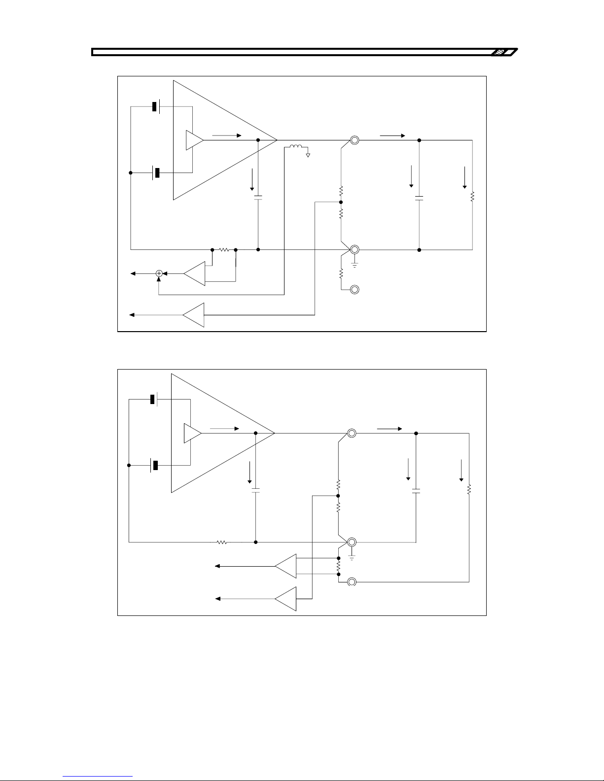
4.4 Operation example in constant current + constant voltage mode
HVA4321
4-41
Figure4-50. Constant current constant voltage mode (total mode)
Figure4-51. Constant current constant voltage mode (load mode)
In constant current + constant voltage mode, the current detection circuit detects AC components and the
voltage detection circuit detects DC components for independent control.
Total mode and load mode can be used same as normal constant current mode.
内部容量
出力端子
配線の容量
負荷抵抗
電流検出抵抗
電流検出抵抗
(トータル用)
(ロード用)
電流モニタ
OUTPUT Hi
OUTPUT Lo
TOTAL
LOAD
Iout
Ii nt
Istr
Il oad
Iamp
Iac
Idc
CT
電圧モニタ
Output terminal
Load
resistance
Wire capacit
y
Current detection
resistance
(
for total
)
Current monitor
Voltage monitor
Current detection resistance
(for load)
Internal capacit
y
内部容量
出力端子
配線の容量
負荷抵抗
電流検出抵抗
電流検出抵抗
(トータル用)
(ロード用)
電流モニタ
OUTPUT Hi
OUTPUT Lo
TOTAL
LOAD
Iout
Ii nt
Istr
Il oad
Iamp
Idc+Iac
電圧モニタ
Output terminal
Load
resistance
Wire capacit
y
Current detection
resistance
(
for total
)
Current monitor
Voltage monitor
Current detection resistance
(for load)
Internal capacit
y
Page 98
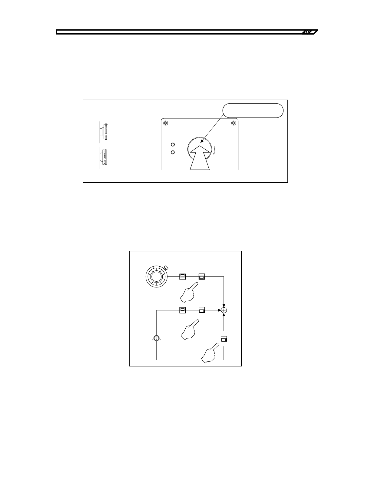
4.4 Operation example in constant current + constant voltage mode
HVA4321
4-42
4.4.1 Panel setting
a) Internal high voltage DC power supply OFF
When HIGH VOLTAGE POWER SUPPLY switch is not OFF, press the button until a "click" sound is
heard. When a click sound is heard, the switch is locked in OFF status. The internal high voltage DC
power supply is always OFF.
Figure4-52. Internal high voltage DC power OFF
b) Signal system OFF
Turn the internal DC bias knob to the leftmost position to minimize the value. Turn OFF the switches of
DC BIAS, OSC INPUT and EXT DC BIAS INPUT.
Figure4-53. Switch settings
DC BIAS
0-10
kV
+
-
ON
OFF
ON
OFF
ON
OFF
INVERT
NORMAL
GAIN
HIGHVOLTAGE
POWER SUPPLY
PUSH OFF
ON
OFF
危険防止のた め 、 出力の配線を 変更する と き は必ず
上のス イ ッ チを 押し て H V 電源を O F F し て く だ さ い。
PULL ON
カチッと音がするまで
押し ま す。
ロックされた状態
オフ
オン
側面より
From side
ON
OFF
Locked status
Press the switch until a click
sound is heard.
Page 99
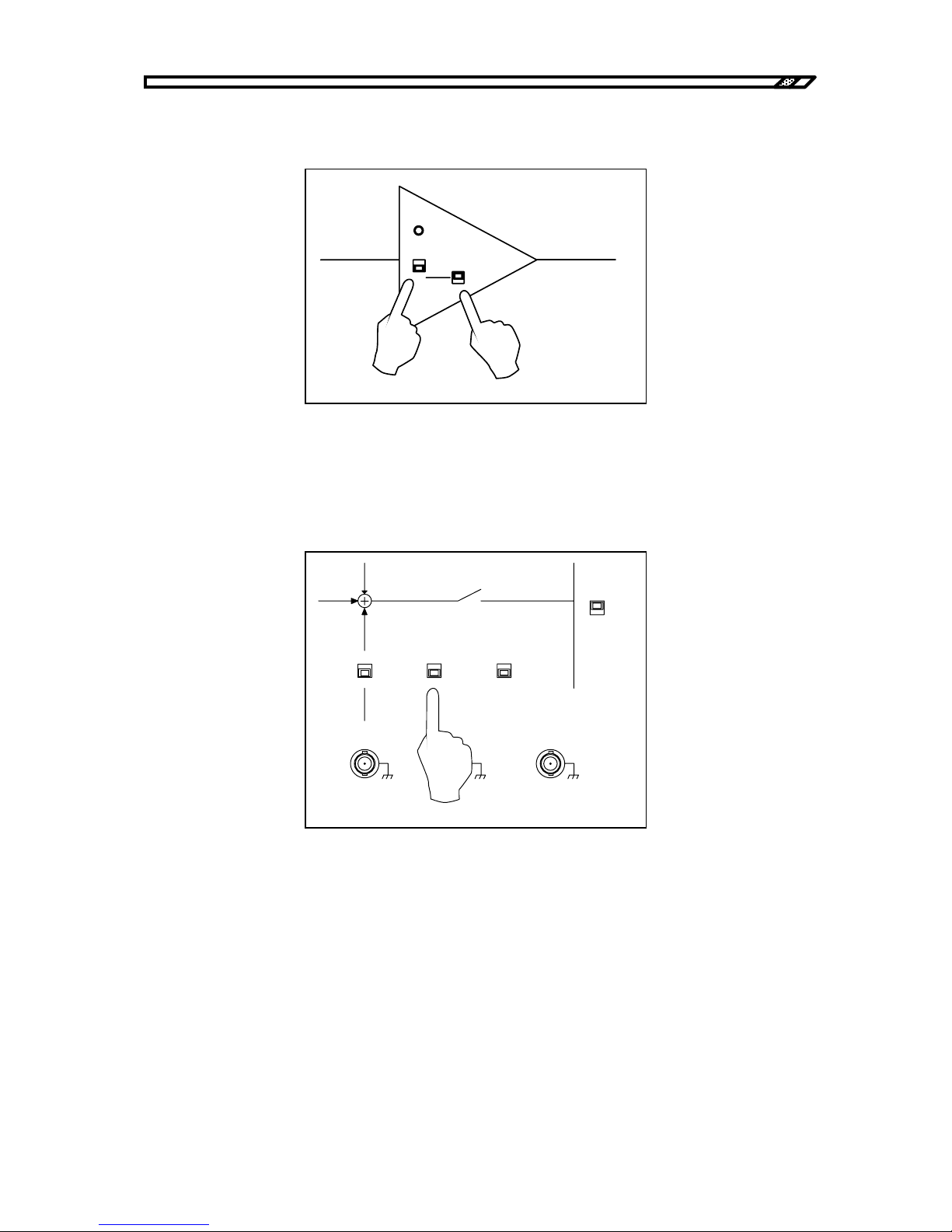
4.4 Operation example in constant current + constant voltage mode
HVA4321
4-43
c) Output mode settings
Set the output mode switch to CC. Set the DC BIAS to CV.
Figure4-54. Output mode settings
d) Remote/local settings
To operate this unit from the panel, set the ON/OFF CONTROL switch to LOCAL.Refer to "4.6 Remote
control operation" for remote control operation.
Figure4-55. Local settings
OVERLOAD
CV
1kV/1V
CC
1mA/1V
DC BIAS
CV
CC
CV
1kV/1V
CC
1mA/1V
CURRENT
SELECT
LOAD
TOTAL
ON/OFF
CONTROL
REMOTE
LOCAL
ON
OFF
EXT DC BI AS
OUTPUT
TTL(Lo:ON)
Zout 10k
Ω
SIGNAL ON/OFF STATUS
OUTPUT
MONITOR
1V/ 1kV
Zout 50
Ω
VOLTAGE
CURRENT
±
10V MAX
Zi n 10 k
Ω
1V/1mA
Zout 50
Ω
Page 100
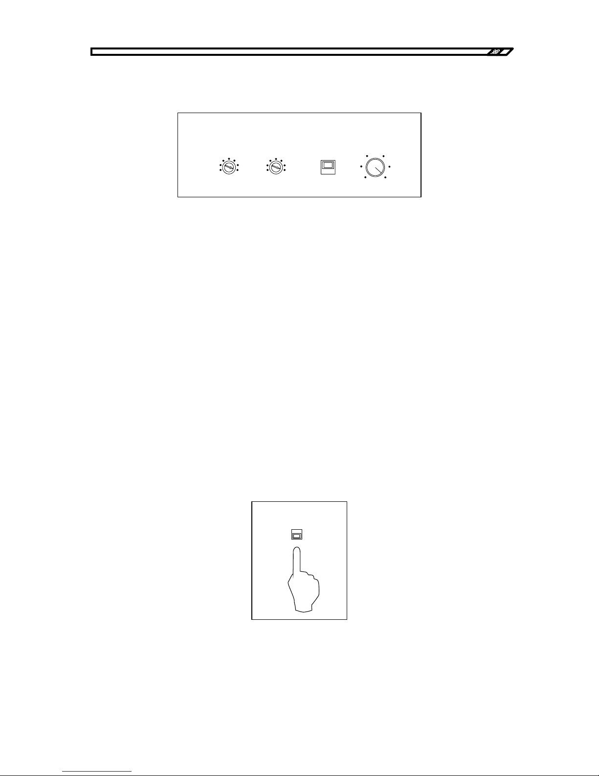
4.4 Operation example in constant current + constant voltage mode
HVA4321
4-44
e) Output limiter settings
To limit the output voltage and output current, set the limiter level as required.
Figure4-56. Limiter settings
Voltage limiter
The voltage limiter function can limit the maximum value of the output voltage independently for
positive and negative values in the range from ±5 kV to ±10 kV.
For example, the output is sufficient up to ±8 kV, set the VOLTAGE LIMITER to 8 kV and -8 kV.
When voltage limitation is not required, set it to MAX.
Current limiter
The current limiter function can limit the average value of the output current in the range from 0 mA to
±10 mA.
For example, to limit the output current up to 5 mA, set it to 5 mA.
When current limitation is not required, set it to 10 mA which is turned to the rightmost position.
LIMIT/TRIP
Set the protection mode for activation of the current limiter. When LIMIT is selected, current is limited
to the set current. When TRIP is selected, the input signal is immediately OFF for activation of the
current limiter circuit and the output is 0V.
Select either one as required.
f) Current monitor mode settings
In total mode, set it to TOTAL CURRENT. In load mode, set it to LOAD CURRENT.
Figure4-57. Current monitor mode settings
TRIP
VOLTAGE(kV)
-5
-10
MAX
5
10
MAX
LI MIT
DC CURRENT( mA)
0
10
LI MITER
CURRENT
SELECT
LOAD
TOTAL
 Loading...