

Page 1
Indoor/Outdoor Security System
with Quad Monitor
User’s Manual
4919539
Page 2

Important!
Please read this booklet carefully before installing or using these units.
WARNING - These units should ONLY be opened by an authorized technician
if service is required.
Safety Precautions
For correct and safe operation of this system, it is essential that installers,
end-users and service technicians should follow all safety procedures outlined
in this manual. Specific Warning and Caution statements (and/or symbols) are
marked on the units where needed.
Warning and Caution Statements
“WARNING” indicates a situation where failure to follow proper
procedures can cause personal injury.
“CAUTION” indicates a situation where failure to follow proper
procedures can cause damage to the equipment.
Page 3
1
Basic Camera to 14” CRT Monitor installation
1. Unpack all parts from the packing box.
2. Install or mount the camera at the desired location. Do not place the camera directly into
sunlight or high light.
3. Lead the DIN cord back to your television or monitor.
NOTE:
1. To protect camera, do not expose to excessive dust or humidity.
2. Handle with care. Do not place in a location subject to vibration.
3. Do not place camera in a location subject to direct sunlight or high light.
REMEMBER: Never aim camera directly into the sun.
Camera to 14” CRT Monitor Installation Chart
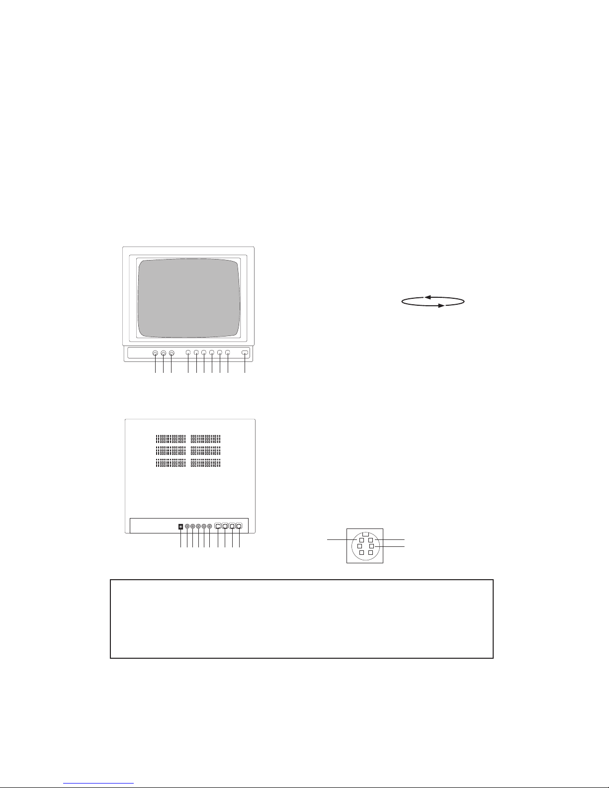
Front Panel
Rear Panel:
1 2 3 4 5 6 7 8 9 10
1. Horizontal synchronization
2. Brightness
3. Contrast
4. QUAD
5. AUTO SCAN (CAM1, CAM2, CAM3, CAM4, QUAD)
The interval period for
switching is every 4 seconds.
6. Single picture (1#)
7. Single picture (2#)
8. Single picture (3#)
9. Single picture (4#)
10. Power
1. DC input
2. Video input (1#)
3. Video input (2#)
4. Video input (3#)
5. Video input (4#)
6. Video output
7. (1#) 6 pins plug
8. (2#) 6 pins plug
9. (3#) 6 pins plug
10. (4#) 6 pins plug)
Ground
DC 12V
Video input
CAUTION:
A distorted picture will appear if the Video input and Din input are connected to the
same channel (EX. CH 1 for Video input and CH1 for Din input) and to the same
display at the same time. Please pay attention to the installation procedure before
installing the system.
1 2 3 4 5 6 7 8 9 10
Page 4

2
Steps
1. Press “QUAD” button, it will display QUAD picture .
2. Press down “AUTO-SCAN” button, the 4 images from Camera 1-4 including “QUAD”
image will be automatically switched at rate of 4 sec one by one.
3. Press Camera 1-4 button, it will display corresponding full screen picture diagram of
the selected camera.
Camera 1 Camera 4
Camera 2 Camera 3
Parts of the Camera
A. Mounting bracket
B. IR LED
C. Camera Din Connector
D. Camera Lens
Note:
A) The RCA video inputs can be
connected with other types of
cameras such as a camcorder
or DVD for entertainment.
B) The RCA video output can be
connected to VCR for recording
or to TV for larger screen display.
A
B
D
C
E
A
B
C
D
Page 5

3
Installing and Connecting the Devices
Select a suitable installation site from which you want to monitor the desired location.
A suitable installation site must have the following features:
• Location must be located in a dry place
• As dust free as possible
• Little vibrations
• Good air circulation
• Must be located near a wall outlet in close vicinity
Select a location that is not screened off by reinforced concrete walls, mirrors, metal
shelves, etc. Close to the sender respectively receiver, there should not be any appliances
with strong electric fields (eg. cell phones, walkie-talkies, electric engines, etc.).
The above points could severely impair radio transmission respectively reduce the range.
Fastening the wall bracket
Din Jack to
TV monitor
• Look for a suitable place for mounting (possibly with
a socket)
• Screw the wall bracket with the supplied screws to a
suitable wall or a suitable platform use dowels if
relevant.
• Guide the tripod thread of the wall bracket into the
thread hole of the camera and screw each of them to
one another.
• Align the camera and screw the lateral locking bolt
tight.
Page 6

4
Specifications
Camera 14” Monitor
Operating Voltage N/A 18 V DC
Tube 35cm, 14” diagonal B/W tube,
90˚ deflection
Picture Element 5100 x 490 (NTSC)
628 x 562 (PAL)
Brightness 0 Lux
Video Output Level 1 Vp-p / 75 Ohm
Video Input 1) 4 channel DIN looping input
Composite video signal 1.0 Vp-p
74 Ohm or HI-Z
2) 4 channel input RCA looping
Menu Control Brightness, Contrast,
Vertical sync, Horizontal sync
Image Sensor 1/4” b/w CMOS
Power Consumption 1.3W (max) 30W
Horizontal Resolution 300 TV lines >800 TV lines
Scanning Linearity <5%
Scanning Geometry <2%
Image b/w b/w
Over Scan 6%
Loss Scan 5%
Direct Current Change Yes
Operating Temperature 14˚F to 122˚F (-10˚C to +50˚C) 32˚F to 104˚F (0˚C to +40˚C)
Operating Humidity 10 - 90%
Weight 502 oz (140g) 299 oz (8500g)
Dimensions without antenna 4 x 1.5 x 1.5 inches 13 x 12 x 12 inches
L x W x H (100 x 38 x 40mm) (335 x 298 x 298mm)
Parts Included:
1. 14” B/W Monitor 1 x pc
2. Outdoor B/W Camera x 4 pcs
3. 60 ft (18m) Weatherproof cable x 4 pcs
4. Camera bracket x 4 pcs
5. 18V DC Power supply x 1 pc
Page 7

5
Who is Providing This Warranty?
• Orbyx Electronics, LLC (“Orbyx”), as the distributor of this Nexxtech
TM
product (your “Product”).
What Does This Warranty Cover?
• This warranty covers defects in materials or workmanship in your Product under normal use and conditions.
What is the Period of Coverage?
• This warranty covers your Product for 90 days from the original purchase date.
Who Is Covered?
• This warranty covers the original consumer purchaser. Coverage terminates if you sell or otherwise transfer your
Product.
What Will We Do To Correct Problems?
• We will repair your Product or replace your Product with a new or reconditioned equivalent product, at our option.
How Do You Get Service?
• Call Orbyx TOLL FREE at 1-866-363-3059 for instructions for obtaining warranty service from Orbyx’s authorized
service providers.
• Or, return your Product directly to the retail store from which you purchased the Product.
• When you obtain service for your Product, you must provide a purchase receipt (or other proof of the original pur
-
chase date) and a description of the defect(s).
What Does This Warranty Not Cover?
• This warranty DOES NOT COVER:
• damage due to misuse, abuse, alteration, unauthorized repair, or accident (such as improper electrical current);
• damage due to “acts of God” (such as lightning) or other contingencies beyond our control;
• cosmetic damage;
• externally generated static, signal reception or antenna problems not caused by your Product; or batteries.
• This warranty also DOES NOT COVER, and in no case will we be liable for, any incidental damages (such as transportation costs to and from an authorized service provider, or loss of time) or consequential damages (such as costs
of repairing or replacing other property which is damaged, including tapes, discs, speakers not included with your
Product or other accessories, or external electrical systems) resulting from the use of your Product. Some states do
not allow the exclusion or limitation of incidental or consequential damages, so the above limitation or exclusion may
not apply to you.
• Defacing the serial number, or using your Product for commercial or institutional purposes, voids this warranty.
Are There Other Warranties?
• There are no express warranties other than those expressed herein. Neither the sales personnel nor any other
person is authorized to make any other warranties or to extend the duration of any warranties.
• ANY IMPLIED WARRANTIES, INCLUDING ANY IMPLIED WARRANTY OF MERCHANTABILITY (AN UNWRITTEN
WARRANTY THAT A PRODUCT IS FIT FOR ORDINARY USE), ARE LIMITED TO 90 DAYS. Some states do not
allow limitations on how long an implied warranty lasts, so the above limitation may not apply to you.
How Does State Law Apply?
• This warranty gives you specific legal rights, and you may also have other rights which vary from state to state.
ORBYX ELECTRONICS WARRANTY
ORBYX Electronics warrants that this product will be free from defects in materials and workmanship for a period of ninety
(90) days from the date of purchase. Within this period, simply take the product and your proof of purchase to any ORBYX
Electronics store or dealer and the product will be repaired without charge for parts and labour. ORBYX Electronics
reserves the right to charge for transportation. Any product which has been subject to misuse or accidental damage is
excluded from this warranty.
This warranty is only applicable to a product purchased through ORBYX Electronics’ company owned stores and dealers
and to a product that is presented for repair in a country where ORBYX Electronics offers the product for sale. While this
warranty does not confer any legal rights other than those set out above, you may have additional statutory rights which
will vary under the laws of the various countries, states, province and other governmental entities in which ORBYX Electronics operates. This warranty is subject to all statutory rights you may have in the country of purchase.
Distributed exclusively in the U.S. by
Orbyx Electronics, LLC
501 South Cheryl Lane,
Walnut, CA 91789
Imported in Canada for/Importé au Canada pour
Orbyx Electronics,
Concord, Canada, L4K 4M3
Manufactured in China
For product support please contact
www.orbyxelectronics.com or 1-866-363-3059
 Loading...